EP2815921A1 - Control of operation of an automotive direction indicators - Google Patents
Control of operation of an automotive direction indicators Download PDFInfo
- Publication number
- EP2815921A1 EP2815921A1 EP13425085.1A EP13425085A EP2815921A1 EP 2815921 A1 EP2815921 A1 EP 2815921A1 EP 13425085 A EP13425085 A EP 13425085A EP 2815921 A1 EP2815921 A1 EP 2815921A1
- Authority
- EP
- European Patent Office
- Prior art keywords
- steering wheel
- motor vehicle
- angle
- direction indicator
- max
- Prior art date
- Legal status (The legal status is an assumption and is not a legal conclusion. Google has not performed a legal analysis and makes no representation as to the accuracy of the status listed.)
- Withdrawn
Links
Images

Classifications
-
- B—PERFORMING OPERATIONS; TRANSPORTING
- B60—VEHICLES IN GENERAL
- B60Q—ARRANGEMENT OF SIGNALLING OR LIGHTING DEVICES, THE MOUNTING OR SUPPORTING THEREOF OR CIRCUITS THEREFOR, FOR VEHICLES IN GENERAL
- B60Q1/00—Arrangement of optical signalling or lighting devices, the mounting or supporting thereof or circuits therefor
- B60Q1/26—Arrangement of optical signalling or lighting devices, the mounting or supporting thereof or circuits therefor the devices being primarily intended to indicate the vehicle, or parts thereof, or to give signals, to other traffic
- B60Q1/34—Arrangement of optical signalling or lighting devices, the mounting or supporting thereof or circuits therefor the devices being primarily intended to indicate the vehicle, or parts thereof, or to give signals, to other traffic for indicating change of drive direction
- B60Q1/346—Arrangement of optical signalling or lighting devices, the mounting or supporting thereof or circuits therefor the devices being primarily intended to indicate the vehicle, or parts thereof, or to give signals, to other traffic for indicating change of drive direction with automatic actuation
-
- B—PERFORMING OPERATIONS; TRANSPORTING
- B60—VEHICLES IN GENERAL
- B60Q—ARRANGEMENT OF SIGNALLING OR LIGHTING DEVICES, THE MOUNTING OR SUPPORTING THEREOF OR CIRCUITS THEREFOR, FOR VEHICLES IN GENERAL
- B60Q1/00—Arrangement of optical signalling or lighting devices, the mounting or supporting thereof or circuits therefor
- B60Q1/26—Arrangement of optical signalling or lighting devices, the mounting or supporting thereof or circuits therefor the devices being primarily intended to indicate the vehicle, or parts thereof, or to give signals, to other traffic
- B60Q1/34—Arrangement of optical signalling or lighting devices, the mounting or supporting thereof or circuits therefor the devices being primarily intended to indicate the vehicle, or parts thereof, or to give signals, to other traffic for indicating change of drive direction
- B60Q1/40—Arrangement of optical signalling or lighting devices, the mounting or supporting thereof or circuits therefor the devices being primarily intended to indicate the vehicle, or parts thereof, or to give signals, to other traffic for indicating change of drive direction having mechanical, electric or electronic automatic return to inoperative position
-
- B—PERFORMING OPERATIONS; TRANSPORTING
- B62—LAND VEHICLES FOR TRAVELLING OTHERWISE THAN ON RAILS
- B62D—MOTOR VEHICLES; TRAILERS
- B62D15/00—Steering not otherwise provided for
- B62D15/02—Steering position indicators ; Steering position determination; Steering aids
- B62D15/021—Determination of steering angle
Definitions
- the present invention relates to control of operation of an automotive direction indicators, in particular to automatic switching off of the direction indicators upon completion of the manoeuvre that required their activation.
- automotive direction indicators are traditionally activated by the driver via a lever specially dedicated to this function and forming part of the so-called steering column switch, which, as is known, is a device located behind the steering wheel and equipped with a series of levers through which the driver can control the operation of a series of on-board devices such as the direction indicators, the front and rear screen wipers, the front and rear lights, etc.
- the direction indicators may be deactivated in two ways: either manually by the driver, via the same dedicated lever, or automatically via a specially provided mechanical deactivation device comprising a coupling, or prong, that engages a bevel gear wheel integral with the steering wheel and which deactivates the direction indicators while steering towards the position the steering wheel had when the direction indicators were activated.
- this mechanical device In order for this mechanical device to perform its function of deactivating the direction indicators, it is necessary that the steering wheel is steered, in the direction when the direction indicator was switched on, by a fixed steering wheel angle, typically 90°, starting from the steering wheel angle when the direction indicators are activated, otherwise this mechanical device is not able to deactivate the direction indicators when the driver realigns the steering wheel.
- This type of direction indicator deactivation device has a series of drawbacks, the main ones of which are represented by the fact of requiring that it be mounted on the steering column and the fact that in certain manoeuvres, such as leaving roundabouts or using motorway slip roads, this device fails to deactivate the direction indicators.
- DE 10 2006 042 966 A1 discloses an automotive direction indicator system in which the direction indicator signals are automatically cancelled upon determining the completion of the manoeuvre that required their activation, where the completion of the manoeuvre is determined on the basis of the motor vehicle's steering angle and the "distance" from a plurality of predetermined manoeuvres, and where the steering angle is determined on the basis of the radii of curvature of the bend line followed by the motor vehicle and the speed of driving through this bend.
- DE 19534087 A1 discloses an electronic system for automatically resetting a motor vehicle direction indicator switch, arranged to ensure reliable reset under various driving conditions and in which the electronic automatic reset system comprises a first sensor device to detect the direction and angle of rotation of the motor vehicle's steering wheel, a second sensor device arranged to measure the value of at least one dynamic quantity of the motor vehicle, conveniently comprising one or more from among a motor vehicle speed sensor, a motor vehicle yaw sensor and two ABS sensors associated with the motor vehicle's two front wheels, and an electronic reset device arranged to reset the direction indicator switch on the basis of the signals generated by the two sensor devices.
- the electronic automatic reset system comprises a first sensor device to detect the direction and angle of rotation of the motor vehicle's steering wheel, a second sensor device arranged to measure the value of at least one dynamic quantity of the motor vehicle, conveniently comprising one or more from among a motor vehicle speed sensor, a motor vehicle yaw sensor and two ABS sensors associated with the motor vehicle's two front wheels, and an electronic reset device arranged to reset the direction
- the object of the present invention is to provide an automotive electronic direction indicator control system that is operationally simpler than the known solutions and that, at the same time, is able to automatically and reliably deactivate them upon completion of the manoeuvre that required their activation for a wide variety of manoeuvres.
- an automotive electronic direction indicator control system for a motor vehicle is therefore provided, as defined in the appended claims.
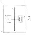
- reference numeral 1 indicates, as a whole, an automotive electronic control system, of which only the parts concerning the control of direction indicators 2 of a motor vehicle 3 are shown.
- the electronic control system 1 essentially comprises an electronic control unit 4 connected to an automotive on-board communication network 5, for example CAN, FlexRay, or others, through which it receives automotive quantities needed to perform the operations for which it has been programmed and in which, among other things, a motor vehicle direction indicator control software is stored to cause, when executed, the electronic control unit to become configured and consequently operate as described in detail below.
- an automotive on-board communication network 5 for example CAN, FlexRay, or others
- the direction indicator control software essentially comprises:
- the direction indicator can then be deactivated at the end of the manoeuvre either manually by the driver or automatically in response to a signal indicating the completion of the manoeuvre, provided by a manoeuvre identifier.
- the steering wheel release angle ⁇ r it might also be convenient to correct the steering wheel release angle ⁇ r depending on the manoeuvre performed by the motor vehicle: for example, in parking manoeuvres, it might be convenient to set the steering wheel release angle ⁇ r to a very high value, for example 600°, so as to avoid deactivation of the direction indicator activated during the manoeuvres.
- the steering wheel angle ⁇ it should be specified that in the automotive field, as in the present description, the convention is adopted according to which the steering wheel angle ⁇ takes positive values when the steering wheel is steered to the left and negative values when steered to the right.
- this is computed as a function of the current motor vehicle speed v , and in particular in a manner such that it is inversely proportional to the current motor vehicle speed v so as to be become larger as the motor vehicle speed approaches zero.
- the reason for this lies in the fact that the more the motor vehicle speed v of the motor vehicle increases in a curve, the more the lateral acceleration to which the driver is subjected increases, thereby inducing him/her to turn the steering wheel less as the motor vehicle speed v increases.
- this is carried out on the basis of the type of manoeuvre performed by the motor vehicle.
- the motor vehicle is travelling along a substantially straight trajectory (therefore ⁇ 0 is less than ⁇ r / 2 ), and the driver activates the left-hand direction indicator and then steers left: if the maximum left-hand steering angle ⁇ max is greater than ⁇ r , then the left-hand direction indicator must be deactivated as soon as the driver steers in the opposite direction and the value of the steering wheel angle ⁇ is just above that of when the direction indicator was activated.
- the deactivation of the left-hand direction indicator must take place as soon as the steering wheel angle ⁇ satisfies an inequality of the type: ⁇ ⁇ ⁇ 0 + ⁇ r k where k is an opportune coefficient that controls the anticipation with which the direction indicator is deactivated when the manoeuvre ends.
- the deactivation strategy of a direction indicator also depends on the relative sign between the initial steering wheel angle ⁇ 0 at which the direction indicator was activated and the maximum steering angle reached during the manoeuvre performed, which, as previously mentioned, is equal to ⁇ max in the case of steering to the left and ⁇ min in the case of steering to the right.
- a motor vehicle that is on a roundabout and takes a turn-off exit can be considered. While travelling around the roundabout, the steering wheel angle ⁇ will be greater than zero (in the case of a country where one drives on the right) and therefore the driver will activate a direction indicator when ⁇ 0 will be greater than zero. As soon as the driver starts to steer to the right to leave the roundabout, the steering wheel angle ⁇ will reach a steering wheel angle ⁇ min : in this case, ⁇ 0 and ⁇ min have different signs.
- deactivation of the direction indicator should not take place when the steering wheel angle ⁇ is close to ⁇ 0 , but when the steering wheel angle ⁇ is close to zero, i.e. when the trajectory is almost perfectly straight.
- the identification of a manoeuvre constituted by the motor vehicle leaving a roundabout can be carried out on the basis of the trend over time of the steering wheel angle ⁇ , which for this manoeuvre is generally of a sinusoidal type.
- the steering wheel angle ⁇ decreases and drops below a certain threshold that corresponds to that which was previously called the minimum right-hand threshold ⁇ d min .
- the steering wheel then continues to be steered to the right until it exceeds another threshold that corresponds to that which was previously called the maximum right-hand threshold ⁇ d max .
- the steering wheel is turned to the left and so the steering wheel angle ⁇ returns first to zero and then, similarly to what happened when steering to the right, it passes a first and a second threshold that correspond to those which were previously called the minimum left-hand threshold ⁇ s min and maximum left-hand threshold ⁇ s max .
- the operations carried out by the direction indicator control software to identify the manoeuvres performed by the motor vehicle can be represented, for each type of manoeuvre that it is wished to identify, by means of a corresponding finite state machine, an example of which is shown in Figure 2 and which regards the deactivation of the left-hand direction indicator at the end of different left-steering manoeuvres.
- n floor ⁇ ⁇ max - ⁇ 0 ⁇ r and an opportune coefficient is indicated as k , the left-hand direction indicator is automatically deactivated when one of the following conditions occurs:
- the first code portion of the direction indicator control software provided to identify the manoeuvre performed by the motor vehicle on the basis of the steering wheel angle ⁇ and the steering wheel angle thresholds ⁇ s min , ⁇ s max , ⁇ d min and ⁇ d max could be omitted.
- those operations performed by the second code portion of the direction indicator control software on the basis of the information provided by the first code portion on the manoeuvre performed by the motor vehicle are not carried out, and in particular the correction of the steering wheel release angle ⁇ r and the blocking of the automatic direction indicator deactivation.
- the automatic deactivation of a direction indicator is carried out when one of the following conditions occurs (valid for a left-hand direction indicator):
Landscapes
- Engineering & Computer Science (AREA)
- Mechanical Engineering (AREA)
- Chemical & Material Sciences (AREA)
- Combustion & Propulsion (AREA)
- Transportation (AREA)
- Steering Control In Accordance With Driving Conditions (AREA)
Abstract
Description
- The present invention relates to control of operation of an automotive direction indicators, in particular to automatic switching off of the direction indicators upon completion of the manoeuvre that required their activation.
- As is known, automotive direction indicators are traditionally activated by the driver via a lever specially dedicated to this function and forming part of the so-called steering column switch, which, as is known, is a device located behind the steering wheel and equipped with a series of levers through which the driver can control the operation of a series of on-board devices such as the direction indicators, the front and rear screen wipers, the front and rear lights, etc.
- Traditionally, the direction indicators may be deactivated in two ways: either manually by the driver, via the same dedicated lever, or automatically via a specially provided mechanical deactivation device comprising a coupling, or prong, that engages a bevel gear wheel integral with the steering wheel and which deactivates the direction indicators while steering towards the position the steering wheel had when the direction indicators were activated.
- In order for this mechanical device to perform its function of deactivating the direction indicators, it is necessary that the steering wheel is steered, in the direction when the direction indicator was switched on, by a fixed steering wheel angle, typically 90°, starting from the steering wheel angle when the direction indicators are activated, otherwise this mechanical device is not able to deactivate the direction indicators when the driver realigns the steering wheel.
- This type of direction indicator deactivation device has a series of drawbacks, the main ones of which are represented by the fact of requiring that it be mounted on the steering column and the fact that in certain manoeuvres, such as leaving roundabouts or using motorway slip roads, this device fails to deactivate the direction indicators.
- Steering column switches have therefore been proposed that comprise electronic direction indicator deactivation devices.
- For example,
DE 10 2006 042 966 A1 discloses an automotive direction indicator system in which the direction indicator signals are automatically cancelled upon determining the completion of the manoeuvre that required their activation, where the completion of the manoeuvre is determined on the basis of the motor vehicle's steering angle and the "distance" from a plurality of predetermined manoeuvres, and where the steering angle is determined on the basis of the radii of curvature of the bend line followed by the motor vehicle and the speed of driving through this bend. -
DE 19534087 A1 discloses an electronic system for automatically resetting a motor vehicle direction indicator switch, arranged to ensure reliable reset under various driving conditions and in which the electronic automatic reset system comprises a first sensor device to detect the direction and angle of rotation of the motor vehicle's steering wheel, a second sensor device arranged to measure the value of at least one dynamic quantity of the motor vehicle, conveniently comprising one or more from among a motor vehicle speed sensor, a motor vehicle yaw sensor and two ABS sensors associated with the motor vehicle's two front wheels, and an electronic reset device arranged to reset the direction indicator switch on the basis of the signals generated by the two sensor devices. - The object of the present invention is to provide an automotive electronic direction indicator control system that is operationally simpler than the known solutions and that, at the same time, is able to automatically and reliably deactivate them upon completion of the manoeuvre that required their activation for a wide variety of manoeuvres.
- According to the present invention, an automotive electronic direction indicator control system for a motor vehicle is therefore provided, as defined in the appended claims.
-
-
Figure 1 shows a functional block diagram of an automotive electronic direction indicator control system according to the present invention; and -
Figure 2 shows an example of a finite state machine representing the operations carried out by a direction indicator control software to identify the manoeuvres performed by a motor vehicle. - The present invention will now be described in detail, with reference to the attached figure, to enable an expert in the field to embody it and use it. Various modifications to the described embodiments will be immediately obvious to experts in the field, and the generic principles described herein can be applied to other embodiments and applications without departing from the scope of the present invention, as defined in the appended claims. Thus, the present invention is not intended to be limited to the embodiments set forth herein, but is to be accorded the widest scope consistent with the principles and features disclosed and claimed herein.
- In
Figure 1 ,reference numeral 1 indicates, as a whole, an automotive electronic control system, of which only the parts concerning the control ofdirection indicators 2 of amotor vehicle 3 are shown. - The
electronic control system 1 essentially comprises anelectronic control unit 4 connected to an automotive on-board communication network 5, for example CAN, FlexRay, or others, through which it receives automotive quantities needed to perform the operations for which it has been programmed and in which, among other things, a motor vehicle direction indicator control software is stored to cause, when executed, the electronic control unit to become configured and consequently operate as described in detail below. - The direction indicator control software essentially comprises:
- a first code portion designed to perform, when executed, the following operations:
- √ receive current steering wheel angle α and current motor vehicle speed v through the on-board communication network,
- √ compute steering wheel angle thresholds, as a function of the current motor vehicle speed v, with which thresholds the current steering wheel angle α is compared to determine the manoeuvre performed by the motor vehicle, and comprising a minimum left-hand threshold αsmin , a maximum left-hand threshold αsmax , a minimum right-hand threshold αdmin and a maximum right-hand threshold αdmax ,
- √ determine a manoeuvre performed by the motor vehicle based on the current steering wheel angle α and the steering wheel angle thresholds, in particular by measuring the time during which the steering wheel angle α satisfies certain relations with the steering wheel angle thresholds, in particular during which it is above and/or below the thresholds, and then by determining the manoeuvre performed by the motor vehicle based on the measured times, and
- a second code portion designed to perform, when executed, the following operations:
- √ receive the current steering wheel angle α and the current motor vehicle speed v through the on-board communication network,
- √ receive information on the manoeuvre performed by the motor vehicle as determined by the first code portion,
- √ store an initial steering wheel angle α 0 at the moment of activation of a direction indicator,
- √ determine minimum and maximum steering wheel angles α min and α max during when the direction indicator is active, these angles representing the maximum steering wheel angles, in absolute values, reached during a steering right manoeuvre and a steering left manoeuvre, respectively,
- √ compute a steering wheel release angle α r , defined as the steering wheel angle beyond which the steering wheel must be steered in the direction indicated by the active direction indicator to cause the automatic deactivation of the direction indicator when, at the end of the steering manoeuvre, the steering wheel is steered in the opposite direction; and
- √ determine if and when to deactivate the active direction indicator based on α, α 0, α min, α max and α r .
- Optionally, it can convenient to disable automatic deactivation of the direction indicators during certain manoeuvres, such as parking in reverse for example, where, regardless of steering wheel movements, it is convenient to keep the direction indicator active until the end of the manoeuvre. The direction indicator can then be deactivated at the end of the manoeuvre either manually by the driver or automatically in response to a signal indicating the completion of the manoeuvre, provided by a manoeuvre identifier.
- Optionally, in some manoeuvres, it might also be convenient to correct the steering wheel release angle α r depending on the manoeuvre performed by the motor vehicle: for example, in parking manoeuvres, it might be convenient to set the steering wheel release angle α r to a very high value, for example 600°, so as to avoid deactivation of the direction indicator activated during the manoeuvres.
- With regard to the steering wheel angle α, it should be specified that in the automotive field, as in the present description, the convention is adopted according to which the steering wheel angle α takes positive values when the steering wheel is steered to the left and negative values when steered to the right.
- With regard to the steering wheel release angle α r , this is computed as a function of the current motor vehicle speed v, and in particular in a manner such that it is inversely proportional to the current motor vehicle speed v so as to be become larger as the motor vehicle speed approaches zero. The reason for this lies in the fact that the more the motor vehicle speed v of the motor vehicle increases in a curve, the more the lateral acceleration to which the driver is subjected increases, thereby inducing him/her to turn the steering wheel less as the motor vehicle speed v increases.
- By way of non-limitative example, the steering wheel release angle α r could be calculated on the basis of the following formula:

where F(v) is an opportune decreasing function of speed, which could also depend on the type of manoeuvre identified. - Instead, with regard to determining if and when to deactivate the direction indicators, this is carried out on the basis of the type of manoeuvre performed by the motor vehicle. Purely by way of example, the case can be considered where the motor vehicle is travelling along a substantially straight trajectory (therefore α 0 is less than α r /2), and the driver activates the left-hand direction indicator and then steers left: if the maximum left-hand steering angle α max is greater than α r , then the left-hand direction indicator must be deactivated as soon as the driver steers in the opposite direction and the value of the steering wheel angle α is just above that of when the direction indicator was activated.
- Translating everything into formulas, the deactivation of the left-hand direction indicator must take place as soon as the steering wheel angle α satisfies an inequality of the type:

where k is an opportune coefficient that controls the anticipation with which the direction indicator is deactivated when the manoeuvre ends. - The deactivation strategy of a direction indicator also depends on the relative sign between the initial steering wheel angle α 0 at which the direction indicator was activated and the maximum steering angle reached during the manoeuvre performed, which, as previously mentioned, is equal to α max in the case of steering to the left and α min in the case of steering to the right.
- Purely by way of example, a motor vehicle that is on a roundabout and takes a turn-off exit can be considered. While travelling around the roundabout, the steering wheel angle α will be greater than zero (in the case of a country where one drives on the right) and therefore the driver will activate a direction indicator when α 0 will be greater than zero. As soon as the driver starts to steer to the right to leave the roundabout, the steering wheel angle α will reach a steering wheel angle α min : in this case, α 0 and α min have different signs. In the phase of realigning the steering wheel to the left, deactivation of the direction indicator should not take place when the steering wheel angle α is close to α 0 , but when the steering wheel angle α is close to zero, i.e. when the trajectory is almost perfectly straight.
- Translating the forgoing into formulas, in the case where α 0 and α min have different signs, deactivation of the direction indicator takes place as soon as an inequality of the following type is satisfied:

in the case of leaving a roundabout on roads where one drives on the right (Italy for example), while the sign of the inequality is inverted on roads where one drives on the left (Great Britain for example). - Instead, with regard to determining the manoeuvre performed by the motor vehicle, it is not possible to provide a single criterion for all manoeuvres, but it is necessary to develop one for each manoeuvre that it is wished to identify.
- Purely by way of example, the identification of a manoeuvre constituted by the motor vehicle leaving a roundabout can be carried out on the basis of the trend over time of the steering wheel angle α, which for this manoeuvre is generally of a sinusoidal type. In fact, upon entering the roundabout, the steering wheel is steered to the right, the steering wheel angle α decreases and drops below a certain threshold that corresponds to that which was previously called the minimum right-hand threshold αdmin. The steering wheel then continues to be steered to the right until it exceeds another threshold that corresponds to that which was previously called the maximum right-hand threshold αdmax . After this, the steering wheel is turned to the left and so the steering wheel angle α returns first to zero and then, similarly to what happened when steering to the right, it passes a first and a second threshold that correspond to those which were previously called the minimum left-hand threshold αsmin and maximum left-hand threshold αsmax.
- Therefore, using the following terms:
- Δt1 as the time for which the steering wheel angle α remains between αdmin and αdmax,
- Δt2 as the time for which the steering wheel angle α remains below αdmax,
- Δt3 as the time taken for the steering wheel angle αa to pass from αdmax to αsmax ,
- The operations carried out by the direction indicator control software to identify the manoeuvres performed by the motor vehicle can be represented, for each type of manoeuvre that it is wished to identify, by means of a corresponding finite state machine, an example of which is shown in
Figure 2 and which regards the deactivation of the left-hand direction indicator at the end of different left-steering manoeuvres. - Essentially, if the integer part of the ratio of the difference between α max and α 0 , and α r , is indicated as n, namely:

and an opportune coefficient is indicated as k, the left-hand direction indicator is automatically deactivated when one of the following conditions occurs: - 1. normal turn

- 2. normal turn (small steering angle)

- 3. normal turn (medium steering angle)

- 4. turn with steering wheel initially turned slightly to the
right 
- 5. turn with steering wheel initially turned fully to the right

- 6. turn aborted

- According to a different embodiment of the present invention, the first code portion of the direction indicator control software provided to identify the manoeuvre performed by the motor vehicle on the basis of the steering wheel angle α and the steering wheel angle thresholds αsmin, αsmax, αdmin and αdmax could be omitted.
- Therefore, according to this embodiment, those operations performed by the second code portion of the direction indicator control software on the basis of the information provided by the first code portion on the manoeuvre performed by the motor vehicle are not carried out, and in particular the correction of the steering wheel release angle αr and the blocking of the automatic direction indicator deactivation.
- Instead, according to this embodiment, the automatic deactivation of a direction indicator is carried out when one of the following conditions occurs (valid for a left-hand direction indicator):
- 1. standard manoeuvre

- 2. anomalous manoeuvre

which, as can be appreciated, are independent of αsmin , αsmax, αdmin and αdmax , which are instead used in the previously described embodiment.

where k1 and k2 are two experimentally-determined calibration coefficients that depend on the driver's driving style.
Claims (8)
- An automotive electronic control system configured to receive and process motor vehicle-related data to control operation of direction indicators of a motor vehicle, by implementing the following operations:• receiving current steering wheel angle (α) and motor vehicle speed (v),• determining an initial steering wheel angle (α 0 ) when a direction indicator is activated,• determining minimum and maximum steering wheel angles (α min , α max ) reached during when the direction indicator is active, the minimum and maximum steering wheel angles (α min, α max ) representing the maximum steering wheel angles, in absolute values, reached by the steering wheel while steering to the right and while steering to the left, respectively,• computing a steering wheel release angle (α r ) based on the current motor vehicle speed (v), the steering wheel release angle (α r ) representing the steering wheel angle (α) beyond which the motor vehicle's steering wheel is to be steered in the direction indicated by the active direction indicator to cause, when at the end of steering manoeuvre the steering wheel is steered in the opposite direction, the automatic deactivation of the operating direction indicator, and• determining if and when to deactivate the active direction indicator based on the current steering wheel angle (α), the initial steering wheel angle (α 0 ), the minimum and maximum steering wheel angles (α min, α max ) and the steering wheel release angle (α r ).
- The automotive electronic control system according to claim 1, wherein the steering wheel release angle (α r ) is computed based on a function that decreases as the current motor vehicle speed (v) increases.
- The automotive electronic control system according to claim 2, wherein the decreasing function depends on the manoeuvre performed by the motor vehicle.
- The automotive electronic control system according to any one of the preceding claims, further configured to disable automatic deactivation of the direction indicators during certain manoeuvres.
- The automotive electronic control system according to any one of the preceding claims, further configured to correct the steering wheel release angle (α r ) depending on the manoeuvre performed by the motor vehicle, so as to avoid automatic deactivation of the active direction indicator during the manoeuvre.
- The automotive electronic control system according to any one of the preceding claims, further configured to:• compute steering wheel angle thresholds as a function of the motor vehicle current speed (v) and comprising a minimum left-hand threshold (αsmin ), a maximum left-hand threshold (αsmax ), a minimum right-hand threshold (αdmin ) and a maximum right-hand threshold (αdmax ); and• determine a manoeuvre performed by the motor vehicle based on the current steering wheel angle (α) and the steering wheel angle thresholds (αsmin, αsmax , αdmin, αdmax ).
- The automotive electronic control system according to claim 6, further configured to determine a manoeuvre performed by the motor vehicle by implementing the following operations:• measuring the time during which the current steering wheel angle (α) satisfies certain relations with the steering wheel angle thresholds (αsmin, αsmax, αdmin, αdmax ); and• determining the manoeuvre performed by the motor vehicle based on the measured times.
- A software loadable in an automotive electronic control system and designed to cause, when executed, the electronic control system to become configured as claimed in any one of the preceding claims.
Priority Applications (4)
| Application Number | Priority Date | Filing Date | Title |
|---|---|---|---|
| EP13425085.1A EP2815921A1 (en) | 2013-06-19 | 2013-06-19 | Control of operation of an automotive direction indicators |
| PCT/IB2014/062451 WO2014203201A1 (en) | 2013-06-19 | 2014-06-19 | Control of operation of automotive direction indicators |
| US14/897,303 US9731648B2 (en) | 2013-06-19 | 2014-06-19 | Control of operation of automotive direction indicators |
| EP14780564.2A EP3010758B1 (en) | 2013-06-19 | 2014-06-19 | Control of operation of automotive direction indicators |
Applications Claiming Priority (1)
| Application Number | Priority Date | Filing Date | Title |
|---|---|---|---|
| EP13425085.1A EP2815921A1 (en) | 2013-06-19 | 2013-06-19 | Control of operation of an automotive direction indicators |
Publications (1)
| Publication Number | Publication Date |
|---|---|
| EP2815921A1 true EP2815921A1 (en) | 2014-12-24 |
Family
ID=49000428
Family Applications (2)
| Application Number | Title | Priority Date | Filing Date |
|---|---|---|---|
| EP13425085.1A Withdrawn EP2815921A1 (en) | 2013-06-19 | 2013-06-19 | Control of operation of an automotive direction indicators |
| EP14780564.2A Not-in-force EP3010758B1 (en) | 2013-06-19 | 2014-06-19 | Control of operation of automotive direction indicators |
Family Applications After (1)
| Application Number | Title | Priority Date | Filing Date |
|---|---|---|---|
| EP14780564.2A Not-in-force EP3010758B1 (en) | 2013-06-19 | 2014-06-19 | Control of operation of automotive direction indicators |
Country Status (3)
| Country | Link |
|---|---|
| US (1) | US9731648B2 (en) |
| EP (2) | EP2815921A1 (en) |
| WO (1) | WO2014203201A1 (en) |
Cited By (3)
| Publication number | Priority date | Publication date | Assignee | Title |
|---|---|---|---|---|
| DE102023211472A1 (en) * | 2023-11-17 | 2025-05-22 | Volkswagen Aktiengesellschaft | Method for operating a direction change indicator in a motor vehicle, data processing device, computer program product and motor vehicle |
| EP4559753A1 (en) * | 2023-11-24 | 2025-05-28 | Volvo Truck Corporation | Dynamically-controlled automatic turn signal cancellation in a vehicle |
| US12594877B2 (en) | 2023-11-24 | 2026-04-07 | Volvo Truck Corporation | Automatic turn signal cancellation in a vehicle for a roundabout |
Families Citing this family (5)
| Publication number | Priority date | Publication date | Assignee | Title |
|---|---|---|---|---|
| CN111016928B (en) * | 2014-12-12 | 2023-06-27 | 索尼公司 | Automatic driving control device, automatic driving control method and program |
| JP6464107B2 (en) * | 2016-02-22 | 2019-02-06 | 本田技研工業株式会社 | Driving support device |
| CN106828287B (en) * | 2017-02-22 | 2020-03-03 | 北京经纬恒润科技有限公司 | Headlamp rotation control method, device and system |
| WO2020173543A1 (en) * | 2019-02-25 | 2020-09-03 | Volvo Truck Corporation | Computer-implemented method for automatically deactivating the left or right turn signals of a vehicle at the end of a turn |
| CN116160949B (en) * | 2023-03-06 | 2026-03-10 | 奇瑞新能源汽车股份有限公司 | Automatic control method and system for turn signal, medium, electronic equipment and vehicle |
Citations (8)
| Publication number | Priority date | Publication date | Assignee | Title |
|---|---|---|---|---|
| DE19534087A1 (en) | 1995-09-14 | 1997-03-20 | Kostal Leopold Gmbh & Co Kg | Resetting system for motor vehicle directional indicator signal switch |
| DE19941308A1 (en) * | 1999-08-31 | 2001-03-01 | Opel Adam Ag | Circuit for automatic switch-off of vehicle's manually switched-on flashing light, deactivates flashing lights depending on sensor-detected steering movements in a given direction |
| FR2814998A1 (en) * | 2000-10-05 | 2002-04-12 | Renault | DEVICE FOR CONTROLLING DIRECTION INDICATOR LIGHTS WITH ELECTRONIC STOP |
| US20060187016A1 (en) * | 2004-07-08 | 2006-08-24 | Masaki Tsukida | Direction indicator |
| DE102006042966A1 (en) | 2006-09-13 | 2008-03-27 | Bayerische Motoren Werke Ag | Direction indicating system for motor vehicle, has processor device arranged such that bending angle is determined based on determined turning radii and speeds, where driving maneuver is completely determined based on bending angle |
| DE102007036633A1 (en) * | 2007-08-03 | 2009-02-05 | Man Nutzfahrzeuge Ag | Device for activation and deactivation of direction indicators in motor vehicle, has actuating devices for indicating direction of travel, where central on-board computer processes signal data from actuation devices |
| JP2011131631A (en) * | 2009-12-22 | 2011-07-07 | Tokai Rika Co Ltd | Turn signal lighting control device |
| FR2967376A1 (en) * | 2010-11-16 | 2012-05-18 | Jtekt Europe Sas | Control method for controlling indicator lights during change in direction of motor vehicle, involves noting whether rotation angle of steering wheel is returned to reference position to switch off indicator lights |
Family Cites Families (2)
| Publication number | Priority date | Publication date | Assignee | Title |
|---|---|---|---|---|
| US4333071A (en) * | 1980-08-07 | 1982-06-01 | Hiroshi Kira | Self-cancelling apparatus for vehicle turn indicators |
| US4962366A (en) * | 1982-01-08 | 1990-10-09 | Honda Giken Kogyo Kabushiki Kaisha | Automatic turn signal cancelling apparatus |
-
2013
- 2013-06-19 EP EP13425085.1A patent/EP2815921A1/en not_active Withdrawn
-
2014
- 2014-06-19 EP EP14780564.2A patent/EP3010758B1/en not_active Not-in-force
- 2014-06-19 US US14/897,303 patent/US9731648B2/en active Active
- 2014-06-19 WO PCT/IB2014/062451 patent/WO2014203201A1/en not_active Ceased
Patent Citations (8)
| Publication number | Priority date | Publication date | Assignee | Title |
|---|---|---|---|---|
| DE19534087A1 (en) | 1995-09-14 | 1997-03-20 | Kostal Leopold Gmbh & Co Kg | Resetting system for motor vehicle directional indicator signal switch |
| DE19941308A1 (en) * | 1999-08-31 | 2001-03-01 | Opel Adam Ag | Circuit for automatic switch-off of vehicle's manually switched-on flashing light, deactivates flashing lights depending on sensor-detected steering movements in a given direction |
| FR2814998A1 (en) * | 2000-10-05 | 2002-04-12 | Renault | DEVICE FOR CONTROLLING DIRECTION INDICATOR LIGHTS WITH ELECTRONIC STOP |
| US20060187016A1 (en) * | 2004-07-08 | 2006-08-24 | Masaki Tsukida | Direction indicator |
| DE102006042966A1 (en) | 2006-09-13 | 2008-03-27 | Bayerische Motoren Werke Ag | Direction indicating system for motor vehicle, has processor device arranged such that bending angle is determined based on determined turning radii and speeds, where driving maneuver is completely determined based on bending angle |
| DE102007036633A1 (en) * | 2007-08-03 | 2009-02-05 | Man Nutzfahrzeuge Ag | Device for activation and deactivation of direction indicators in motor vehicle, has actuating devices for indicating direction of travel, where central on-board computer processes signal data from actuation devices |
| JP2011131631A (en) * | 2009-12-22 | 2011-07-07 | Tokai Rika Co Ltd | Turn signal lighting control device |
| FR2967376A1 (en) * | 2010-11-16 | 2012-05-18 | Jtekt Europe Sas | Control method for controlling indicator lights during change in direction of motor vehicle, involves noting whether rotation angle of steering wheel is returned to reference position to switch off indicator lights |
Cited By (4)
| Publication number | Priority date | Publication date | Assignee | Title |
|---|---|---|---|---|
| DE102023211472A1 (en) * | 2023-11-17 | 2025-05-22 | Volkswagen Aktiengesellschaft | Method for operating a direction change indicator in a motor vehicle, data processing device, computer program product and motor vehicle |
| DE102023211472B4 (en) * | 2023-11-17 | 2025-10-30 | Volkswagen Aktiengesellschaft | Method for operating a direction change indicator in a motor vehicle, data processing device, computer program product and motor vehicle |
| EP4559753A1 (en) * | 2023-11-24 | 2025-05-28 | Volvo Truck Corporation | Dynamically-controlled automatic turn signal cancellation in a vehicle |
| US12594877B2 (en) | 2023-11-24 | 2026-04-07 | Volvo Truck Corporation | Automatic turn signal cancellation in a vehicle for a roundabout |
Also Published As
| Publication number | Publication date |
|---|---|
| WO2014203201A8 (en) | 2015-08-27 |
| EP3010758B1 (en) | 2017-08-09 |
| WO2014203201A1 (en) | 2014-12-24 |
| US20160129831A1 (en) | 2016-05-12 |
| US9731648B2 (en) | 2017-08-15 |
| EP3010758A1 (en) | 2016-04-27 |
Similar Documents
| Publication | Publication Date | Title |
|---|---|---|
| EP3010758B1 (en) | Control of operation of automotive direction indicators | |
| KR101320223B1 (en) | Method and system for assisting a driver when parking or manoeuvring a motor vehicle | |
| US11780434B2 (en) | Lane change intention estimation of a vehicle | |
| US9623906B2 (en) | Park-steer assist system and method for operating a park-steer assist system | |
| US11383730B2 (en) | Method and device for assisting a driver during the deactivation of a highly automated driving mode of a vehicle | |
| KR101871076B1 (en) | Method for operating a driver assistance device for autonomously driving a motor vehicle and motor vehicle | |
| US9381922B2 (en) | Detection of parking maneuver in a motor vehicle | |
| US20090128315A1 (en) | Method for determining absolute tire rolling circumferences and tire pressure control system | |
| US20180056868A1 (en) | Method and apparatus to determine trailer pose | |
| KR20190123663A (en) | Apparatus and method for providing drive path of vehicle | |
| EP2374661A1 (en) | Parallel parking assistant system and method thereof | |
| US20160167661A1 (en) | Method for operating a driver assistance system of a motor vehicle and driver assistance system for a motor vehicle | |
| CN101980916A (en) | Method and device for supporting a driver of a vehicle during the process of leaving a parking space | |
| GB2479998A (en) | A parking system for a vehicle | |
| KR20170024678A (en) | Sensing apparatus for vehicle and sensing method for vehicle | |
| US9650069B2 (en) | Method for controling rear wheel steering | |
| US20120229268A1 (en) | Method and apparatus for vehicular direction indication | |
| CN111655559B (en) | System and method for controlling a motor vehicle to negotiate a low obstacle | |
| US12254705B2 (en) | Method for detecting an exit lane for a motor vehicle | |
| EP4559752A1 (en) | Automatic turn signal cancellation in a vehicle for a roundabout | |
| US9786179B2 (en) | Method and device for assisting a driver of a vehicle during a lane change | |
| EP4444592B1 (en) | Method for operating a vehicle, computer program, control system and vehicle | |
| US20240239346A1 (en) | Method for Operating a Lane-Change Assistance System of a Vehicle, With Speed-Dependent Differentiation of a Subsequent Blinking Signal, Lane-Change Assistance System, and Vehicle | |
| WO2014001067A1 (en) | A park pilot system for a vehicle and a method thereof | |
| CN115195860B (en) | Steering control method and device for vehicle, storage medium, processor and vehicle |
Legal Events
| Date | Code | Title | Description |
|---|---|---|---|
| PUAI | Public reference made under article 153(3) epc to a published international application that has entered the european phase |
Free format text: ORIGINAL CODE: 0009012 |
|
| 17P | Request for examination filed |
Effective date: 20130619 |
|
| AK | Designated contracting states |
Kind code of ref document: A1 Designated state(s): AL AT BE BG CH CY CZ DE DK EE ES FI FR GB GR HR HU IE IS IT LI LT LU LV MC MK MT NL NO PL PT RO RS SE SI SK SM TR |
|
| AX | Request for extension of the european patent |
Extension state: BA ME |
|
| R17P | Request for examination filed (corrected) |
Effective date: 20150623 |
|
| RBV | Designated contracting states (corrected) |
Designated state(s): AL AT BE BG CH CY CZ DE DK EE ES FI FR GB GR HR HU IE IS IT LI LT LU LV MC MK MT NL NO PL PT RO RS SE SI SK SM TR |
|
| 17Q | First examination report despatched |
Effective date: 20160321 |
|
| STAA | Information on the status of an ep patent application or granted ep patent |
Free format text: STATUS: THE APPLICATION IS DEEMED TO BE WITHDRAWN |
|
| 18D | Application deemed to be withdrawn |
Effective date: 20160802 |