EP2815873A1 - An additive layer manufacturing method - Google Patents
An additive layer manufacturing method Download PDFInfo
- Publication number
- EP2815873A1 EP2815873A1 EP14170456.9A EP14170456A EP2815873A1 EP 2815873 A1 EP2815873 A1 EP 2815873A1 EP 14170456 A EP14170456 A EP 14170456A EP 2815873 A1 EP2815873 A1 EP 2815873A1
- Authority
- EP
- European Patent Office
- Prior art keywords
- support
- powder
- product
- successive
- cross
- Prior art date
- Legal status (The legal status is an assumption and is not a legal conclusion. Google has not performed a legal analysis and makes no representation as to the accuracy of the status listed.)
- Granted
Links
Images


Classifications
-
- B—PERFORMING OPERATIONS; TRANSPORTING
- B29—WORKING OF PLASTICS; WORKING OF SUBSTANCES IN A PLASTIC STATE IN GENERAL
- B29C—SHAPING OR JOINING OF PLASTICS; SHAPING OF MATERIAL IN A PLASTIC STATE, NOT OTHERWISE PROVIDED FOR; AFTER-TREATMENT OF THE SHAPED PRODUCTS, e.g. REPAIRING
- B29C64/00—Additive manufacturing, i.e. manufacturing of three-dimensional [3D] objects by additive deposition, additive agglomeration or additive layering, e.g. by 3D printing, stereolithography or selective laser sintering
- B29C64/10—Processes of additive manufacturing
- B29C64/141—Processes of additive manufacturing using only solid materials
- B29C64/153—Processes of additive manufacturing using only solid materials using layers of powder being selectively joined, e.g. by selective laser sintering or melting
-
- B—PERFORMING OPERATIONS; TRANSPORTING
- B22—CASTING; POWDER METALLURGY
- B22F—WORKING METALLIC POWDER; MANUFACTURE OF ARTICLES FROM METALLIC POWDER; MAKING METALLIC POWDER; APPARATUS OR DEVICES SPECIALLY ADAPTED FOR METALLIC POWDER
- B22F10/00—Additive manufacturing of workpieces or articles from metallic powder
- B22F10/20—Direct sintering or melting
- B22F10/28—Powder bed fusion, e.g. selective laser melting [SLM] or electron beam melting [EBM]
-
- B—PERFORMING OPERATIONS; TRANSPORTING
- B22—CASTING; POWDER METALLURGY
- B22F—WORKING METALLIC POWDER; MANUFACTURE OF ARTICLES FROM METALLIC POWDER; MAKING METALLIC POWDER; APPARATUS OR DEVICES SPECIALLY ADAPTED FOR METALLIC POWDER
- B22F10/00—Additive manufacturing of workpieces or articles from metallic powder
- B22F10/40—Structures for supporting workpieces or articles during manufacture and removed afterwards
- B22F10/47—Structures for supporting workpieces or articles during manufacture and removed afterwards characterised by structural features
-
- B—PERFORMING OPERATIONS; TRANSPORTING
- B22—CASTING; POWDER METALLURGY
- B22F—WORKING METALLIC POWDER; MANUFACTURE OF ARTICLES FROM METALLIC POWDER; MAKING METALLIC POWDER; APPARATUS OR DEVICES SPECIALLY ADAPTED FOR METALLIC POWDER
- B22F5/00—Manufacture of workpieces or articles from metallic powder characterised by the special shape of the product
- B22F5/009—Manufacture of workpieces or articles from metallic powder characterised by the special shape of the product of turbine components other than turbine blades
-
- B—PERFORMING OPERATIONS; TRANSPORTING
- B23—MACHINE TOOLS; METAL-WORKING NOT OTHERWISE PROVIDED FOR
- B23K—SOLDERING OR UNSOLDERING; WELDING; CLADDING OR PLATING BY SOLDERING OR WELDING; CUTTING BY APPLYING HEAT LOCALLY, e.g. FLAME CUTTING; WORKING BY LASER BEAM
- B23K15/00—Electron-beam welding or cutting
- B23K15/0006—Electron-beam welding or cutting specially adapted for particular articles or work
-
- B—PERFORMING OPERATIONS; TRANSPORTING
- B23—MACHINE TOOLS; METAL-WORKING NOT OTHERWISE PROVIDED FOR
- B23K—SOLDERING OR UNSOLDERING; WELDING; CLADDING OR PLATING BY SOLDERING OR WELDING; CUTTING BY APPLYING HEAT LOCALLY, e.g. FLAME CUTTING; WORKING BY LASER BEAM
- B23K15/00—Electron-beam welding or cutting
- B23K15/0046—Welding
- B23K15/0086—Welding welding for purposes other than joining, e.g. build-up welding
-
- B—PERFORMING OPERATIONS; TRANSPORTING
- B29—WORKING OF PLASTICS; WORKING OF SUBSTANCES IN A PLASTIC STATE IN GENERAL
- B29C—SHAPING OR JOINING OF PLASTICS; SHAPING OF MATERIAL IN A PLASTIC STATE, NOT OTHERWISE PROVIDED FOR; AFTER-TREATMENT OF THE SHAPED PRODUCTS, e.g. REPAIRING
- B29C64/00—Additive manufacturing, i.e. manufacturing of three-dimensional [3D] objects by additive deposition, additive agglomeration or additive layering, e.g. by 3D printing, stereolithography or selective laser sintering
- B29C64/40—Structures for supporting 3D objects during manufacture and intended to be sacrificed after completion thereof
-
- B—PERFORMING OPERATIONS; TRANSPORTING
- B22—CASTING; POWDER METALLURGY
- B22F—WORKING METALLIC POWDER; MANUFACTURE OF ARTICLES FROM METALLIC POWDER; MAKING METALLIC POWDER; APPARATUS OR DEVICES SPECIALLY ADAPTED FOR METALLIC POWDER
- B22F10/00—Additive manufacturing of workpieces or articles from metallic powder
- B22F10/70—Recycling
- B22F10/73—Recycling of powder
-
- Y—GENERAL TAGGING OF NEW TECHNOLOGICAL DEVELOPMENTS; GENERAL TAGGING OF CROSS-SECTIONAL TECHNOLOGIES SPANNING OVER SEVERAL SECTIONS OF THE IPC; TECHNICAL SUBJECTS COVERED BY FORMER USPC CROSS-REFERENCE ART COLLECTIONS [XRACs] AND DIGESTS
- Y02—TECHNOLOGIES OR APPLICATIONS FOR MITIGATION OR ADAPTATION AGAINST CLIMATE CHANGE
- Y02P—CLIMATE CHANGE MITIGATION TECHNOLOGIES IN THE PRODUCTION OR PROCESSING OF GOODS
- Y02P10/00—Technologies related to metal processing
- Y02P10/25—Process efficiency
Definitions
- the present invention relates to an additive layer manufacturing (ALM) method, and more particularly relates to an ALM for the production of a three-dimensional product via successive fusion of parts of a powder bed, said parts corresponding to successive cross-sections of the product.
- ALM additive layer manufacturing
- Electron Beam Melting is a particular type of ALM technique which is used to form fully dense metal products (such as component parts for gas turbine engines in the aerospace industry). The technique involves using an electron beam in a high vacuum to melt metal powder in successive layers within a powder bed. Metal products manufactured by EBM are fully dense, void-free, and extremely strong.
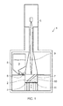
- Figure 1 illustrates a known configuration of apparatus 1 which is used in an EBM method to produce a three-dimensional metal product 2 from metal powder 3.
- the apparatus comprises an adjustable height work platform 4 upon which the product 2 is to be built, a powder dispenser 5 such as a hopper, a rake 6 or other arrangement operable to lay down a thin layer of the powder 3 on the work platform 4 to form the powder bed 7, and an electron beam column 8 for directing and focussing an electron beam 9 downwardly on the powder bed 7 in order to melt parts of uppermost layer of the powder bed 7.
- the entire apparatus is housed within a vacuum housing and the operative parts are computer controlled.
- the electron beam column 8 is energised under the control of the computer to focus the electron beam onto the powder bed 7 and to scan the beam across the powder bed to melt a predetermined area of the top layer of the powder bed 7 and thereby form a cross-section of the three-dimensional product 2.
- the three-dimensional product 2 is built up by the successive laying down of powder layers on the powder bed 7 and melting of the powder in predetermined areas of the layers to form successive cross-sections of the product 2.
- the work platform 4 is lowered successively relative to the electron beam column 8 after each added layer of powder has been melted, ready for the next layer to be laid down on top.
- the work platform 4 starts in an initial position which is higher than the position illustrated in figure 1 , and in which position a first layer of powder of necessary thickness is laid down on the work platform 4 by the rake 6.
- the first layer of powder is typically made thicker than the other applied layers, thereby preventing melt-through by the electron beam 9. This is why the product 2 appears spaced above the work platform 4 within the powder bed 7 in figure 1 .
- the work platform 4 is then successively lowered for the laying down of a new powder layer for the formation of a new cross-section of the product 2.
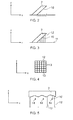
- a downwardly facing surface 10 is defined as one whose orientation enables its projection onto a horizontal two-dimensional plane below it, as illustrated schematically in Figure 2 .
- Previously proposed support structures 12 designed to avoid the problems mentioned above in relation to unsupported downwardly facing surfaces generally consist of an array of thin walls that are manufactured at the same time as the product and from the powder via the same EBM technique. These thin walls are created so as to extend between the downwardly facing surface 10 and another solid surface.
- the other solid surface can either be a base plate 11 on which the product is formed, or a previously formed upwardly facing surface of the product in the case where the downwardly facing surface 10 is formed above such a surface.
- These structures 12 are typically referred to as 'wafers', and are illustrated schematically in figures 3 and 4 .
- the wafers are designed to be removable from the downwardly facing surface 10 by hand or machine tools during a subsequent finishing procedure.
- the thin-walled structures or wafers 12 may be provided in a lattice configuration as viewed from below the downwardly facing surface 10, which thus defines an array of small spaces 13 between the wafers 12. It is common for powder feedstock to become trapped in these spaces 13 as the wafers are built up during the EBM process, and the trapped powder can then be difficult to remove and separate from the fused powder forming the wafers 12 themselves during the subsequent finishing process. The trapped powder is thus typically discarded rather than being recycled for subsequent use. Powder feedstock used to manufacture component parts of gas turbine engines is typically very expensive, so this wastage increases the overall manufacturing cost.
- wafer supports 12 must start on a solid substrate, which as mentioned above can either be an area of the component being manufactured, or an underlying base plate.
- a solid substrate which as mentioned above can either be an area of the component being manufactured, or an underlying base plate.
- the surface finish and geometrical tolerance of the component in contact with the wafers is also reduced and the total foot print of the supported component is increased. Both reduce the manufacturing efficiency for the component
- Distortion of the downwardly facing surface 10 represents another problem that can arise when utilising wafer supports 12. This distortion typically arises from the formation of concave regions 14 on the supported surface in the area between each wafer support, as illustrated schematically in figure 5 .
- an additive layer manufacturing (ALM) method for the production of a three-dimensional product via successive fusion of parts of a powder bed, said parts corresponding to successive cross-sections of the product, the method comprising the steps of: a) laying down a powder layer on said powder bed, and b) focussing energy on a predetermined area of said powder layer to fuse said area of the powder layer and thereby form a cross-section of the product; wherein steps a) and b) are repeated to form successive cross-sections of the product, and wherein at least one of said steps b) involves focussing said energy on an area of the respective powder layer which is at least partially unsupported by a previously formed cross-section of the product to thereby form a downwardly facing surface of the product, the method being characterised in that at least some of said successive steps b) involve focussing energy on a support area of the respective powder layer which is spaced from the predetermined area of the powder layer, to fuse the support area and thereby form successive cross-
- At least some of said successive steps in which energy is focussed on a support area of a respective powder layer also involve focussing energy on a said predetermined area of the powder layer to fuse said area of the powder layer and thereby form a cross-section of the product, the support area and the predetermined area being spaced apart.
- Said support pin preferably extends generally downwardly from said downwardly facing surface of the product.
- Said successive steps in which energy is focussed on a support area of the respective powder layer may involve focussing energy on a plurality of said support areas in spaced relation to one another, to thereby form successive cross-sections of a plurality of said support pins, the support pins being formed in a spaced array within the powder bed.
- said support pins are parallel to one another.
- the pins may be non-parallel to one another.
- the or each support pin is approximately cylindrical, and may optionally have a diameter in the range 0.2mm to 2mm. It should be noted, however, that the pins can have alternative cross-sectional profiles such as, for example, square or hexagonal.
- the or each said support area is circular, and energy is focussed on successive said support areas of respective powder layers which are in alignment to one another to form successive circular cross-sections of the or each support pin which is thus cylindrical.
- the or each support pin may thus be formed so as to extend vertically within the powder bed.
- the or each said support area is approximately elliptical, and energy is focussed on successive said support areas of respective powder layers which are imbricated to form successive elliptical cross-sections of the or each support pin which is thus cylindrical.
- the or each support pin may thus be formed so as to extend non-vertically within the powder bed.
- the or each support pin has a free end which is formed within the powder bed.
- the free end of the or each said support pin is spaced from any other surface of the product, and is also spaced from any base plate used to support the powder bed.
- the free end of the or each said support pin may be formed by focussing energy on an initial support area which is supported only by underlying unfused powder in the powder bed, to fuse said initial support area and thereby form the free end.
- the method involves Electron Beam Melting and is used to manufacture metal products.
- said powder is preferably metal powder, and said steps of focussing energy on said areas of the powder layers preferably involves the use of an electron beam to melt said areas of the powder layers.
- the above-defined method may be used to manufacture a component of a gas turbine engine, and involves the step of removing the or each said support pin from said product to form said component.
- FIGS. 6 and 7 show a product 20 which is manufactured by the method of the invention.
- the product 20 illustrated in figures 6 and 7 is a metal product and is formed via an ALM method from metal powder.
- the product has a horizontally oriented lower surface 21 which is downwardly facing.
- Figure 6 also shows the downwardly facing surface 21 being supported by a plurality of narrow and elongate support pins 22 which extend downwardly from the downwardly facing surface 21.
- Figure 7 shows the arrangement of the support pins 22 as viewed from below the product 20 and shows the support pins 22 arranged in a generally regular array across the downwardly facing surface 20.
- the pins 22 are formed via fusion of the same powder feedstock from which the product 20 is formed, and via a similar technique.
- the pins 22 effectively substitute the wafer support structures 12 of the prior art described above and thus serve to support the downwardly facing surface 21 as the product 20 is built up in a powder bed.
- the size and configuration of the pins can vary, but it has been found that pins having a circular cross-section and a diameter of approximately 0.8mm provide particular advantages over the prior art wafer structures 12.
- a supporting structure for the downwardly facing surface 21 which is formed from support pins 22 of the type illustrated has been found to be quicker and less expensive to produce than the prior art wafer structures 12, which makes their use very significant in a commercial ALM context.
- the supporting pins 22 do not trap un-melted powder feedstock between them to the same degree as prior art wafer structures, and they thus permit more efficient recycling of powder. It has also been found that the supporting pins 22 actually use less powder in their manufacture, which further reduces wastage of powder feedstock.
- the supporting pins 22 can also provide better control and reduction of distortion on the downwardly facing surface 22 and are also more easily removed during subsequent finishing of the product.
- the support pins 22 can be formed so as to have free ends formed within a powder bed, rather than needing to be built up from lower rigid surfaces such as might be defined by other parts of the product, or by a metal base plate inserted within the powder bed.
- Figure 8 illustrates a vertical cross-section through an exemplary product 20 which is used herein to highlight key aspects of the present invention.
- the product 20 has two downwardly facing surfaces, namely a horizontally oriented surface 21 a similar to the one shown in figure 6 , and a sloping surface 21 b which is inclined to the vertical in the orientation of the product shown. Additionally, beneath the sloping surface 21 b, the product 20 also has a vertically oriented surface 23 which is not downwardly facing.
- the method of the present invention can be performed using apparatus generally similar to the apparatus shown in Figure 1 . Accordingly, particular reference is made herein to the use of Electron Beam Melting of metal powder feedstock. However, it is to be noted that the invention is not limited to EBM, and could be embodied in alternative ALM techniques in which a three-dimensional product is formed via successive fusion of parts of a powder bed, said parts corresponding to successive cross-sections of the product.
- Figure 9 illustrates an initial step in the method of manufacturing the product, and shows the work platform 4 of an EBM apparatus in an initial raised position.
- An initial layer 24 of metal powder feedstock is laid on the work table 4 to start a powder bed 25.
- the powder may be spread into the layer 24 via the rake 6 of the apparatus shown in figure 1 .
- the initial layer 24 of the powder bed 25 can be laid thicker than subsequent layers.
- Figure 10 shows a subsequent step in which an electron beam 9 is focussed on and scanned across a predetermined area 26 of the initial powder layer 24.
- the beam thus melts the powder in the predetermined area 26, thereby fusing the area 26 and forming an initial cross-section of the product 20.
- the shape of the cross-section is effectively defined by the shape of the predetermined area 26.
- the table 4 is then lowered and another layer of powder is laid on top of the first layer 24, thereby adding to the powder bed 25, whereupon the electron beam 9 is again focussed on and scanned across an identically sized and positioned predetermined area of the top layer, thereby forming the next cross-section of the product, on top of the first cross-section.
- the steps of laying down a layer of powder and then focussing/scanning the electron beam over a predetermined area of the layer are repeated to form successive cross-sections of the product 20, thereby gradually building the product from the bottom up.
- these steps are repeated to form identical and vertically aligned cross-sections of the product, thereby building up the lower part of the product having the vertical surface 23. It is to be noted that during this stage of the method, the respective predetermined areas 26 of each successive layer of powder are thus all aligned with one another.
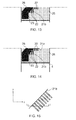
- Figure 11 illustrates a stage during the formation of the product at which the lower part of the product 20 and its vertical surface 23 is complete.
- This drawing therefore shows the final cross-section of the lower part of the product having just been formed by melting a predetermined area 26 of the top layer of powder on the powder bed 25.
- the electron beam is refocused, in turn, on a plurality of small spaced apart support areas 27.
- the support areas are all spaced from the predetermined area of the same layer of powder which is fused to form the cross-section of the lower part of the product 20.
- Figure 12 shows the arrangement of the support areas 27 in plan view.
- the support areas 27 are substantially circular in shape and arranged in a series of rows which cooperate to define a generally regular array.
- the support areas 27 most preferably have a diameter of approximately 0.8 mm.
- each of the support areas 27 melts the powder in those areas, thereby fusing the powder.
- the fused support areas 27 of the top layer of powder thus form initial cross-sections of respective support pins 22 similar to those illustrated in figures 6 and 7 .
- the initial cross-sections of the support pins 22 which are formed in this way define free ends 28 of the respective support pins 22.
- the free ends 28 of the support pins 22 are thus formed in the top layer of the powder bed 25 (at the stage illustrated in figure 11 ), and are spaced from all other rigid structures such as surfaces of the product 20 being formed and the work table 4.
- the initial support areas 27 which are fused to define the ends 28 of the support pins are only supported by underlying powder in the powder bed 25.
- a series of further successive layers of powder then continue to be laid on the powder bed 25.
- the electron beam 9 is focussed on correspondingly shaped and positioned support areas 27 to melt the powder material in the support areas and thereby steadily build up successive cross-sections of the support pins 22, as shown schematically in figure 13 .
- the successive support areas 27 of each powder layer which are melted to form each support pin 22 are thus aligned with one another, such that each support pin 22 is built up vertically.
- the electron beam 9 also continues to be focussed on respective predetermined areas 26 of the layers to melt the powder material in the predetermined areas and thereby define respective cross-sections of the central region of the product 20.
- the predetermined areas 26 of each layer which are melted during this stage of the procedure differ from one another in the sense that each successive predetermined area 26 is slightly larger than the preceding one such that in each layer a region of the predetermined area 26 is partially unsupported by the previously formed cross-section of the central region of the product 20.
- the inclined downwardly facing surface 21 b is thus built up gradually in this way, layer by layer.
- each support pin 22 which was shown being started in Figures 11 and 12 , is eventually completed by its final cross-section being defined by a support area 27 which becomes subsumed by the predetermined area 26 of the respective layer of powder.
- the support pins 22 thus extend outwardly from the inclined downwardly facing surface 21 b, the pins extending vertically downwardly within the powder bed 25 and are parallel to one another.
- Figure 13 also shows a second set of support pins 22 being built up in substantially the same manner as described above; with a series of further support areas 27 of each layer being melted to define successive cross-sections of the support pins 22.
- the second set of support pins 22, shown as incomplete in figure 13 will provide support for the subsequent formed horizontal downwardly facing surface 21 a of the product 20.
- the second set of support pins 22 are formed by melting respective support areas 27 of powder layers in which the partially unsupported predetermined areas 26 are also melted.
- Figure 14 shows a stage in the production process in which the predetermined area 26 of the top powder layer has a size and shape corresponding to the cross-section of the upper region of the product 20.
- Figure 14 thus shows the creation of the first cross-section of the upper region of the product, and hence the horizontal downwardly facing surface 21 a of the product.
- a very significant proportion of the predetermined area 26 of the upper powder layer is unsupported by the previously formed cross-section of the product 20.
- the downwardly facing surface defined by the top predetermined area 26 is supported by the previously built up support pins 22 beneath the surface 21 a, the support pins thus extending downwardly from the surface 21 a.
- the subsequent cross-sections of the relatively wide upper region of the product 20 are then formed by melting substantially identical predetermined regions 26 of successive powder layers in a generally conventional manner.
- the product 20 when the product 20 has been fully formed via the method described above, it may be removed from the EBM apparatus and from the powder bed 25, whereupon the support pins 22 can be removed during a subsequent finishing process.
- the support pins 22 have been found to be significantly easier, and less wasteful, to remove than prior art wafer structures.
- FIG. 15 and 16 illustrate an alternative method in which the pins 22 are formed so to extend non-vertically within the powder bed 25, such that the pins are non-parallel to the vertical working axis of the machine
- Figure 15 shows an inclined downwardly facing surface 21 b of a product, from which depend a plurality of parallel support pins 22. However, as can be seen immediately, the pins 22 make an acute angle to the vertical axis z rather than being oriented vertically as shown in figure 6 .
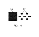
- Figure 16 which illustrates a similar view to figure 12 described above, shows how this achieved.
- the support areas 27 of each powder layer are elliptical in shape, rather than circular as was the case in the embodiment described above and as shown in figure 12 .
- the elliptical support areas 27 pertaining to each support pin are melted in successive powder layers in an imbricated manner, such that the successive horizontal cross-sections of each support pin are partially horizontally offset from one another.
- the support pins 22 are built up so as to still be cylindrical in form, but so that they are non-vertical within the powder bed 25. This type of support structure can be very useful and offers increased flexibility over prior art wafer support structures.
Landscapes
- Engineering & Computer Science (AREA)
- Chemical & Material Sciences (AREA)
- Materials Engineering (AREA)
- Manufacturing & Machinery (AREA)
- Mechanical Engineering (AREA)
- Physics & Mathematics (AREA)
- Optics & Photonics (AREA)
- Plasma & Fusion (AREA)
- Powder Metallurgy (AREA)
Abstract
Description
- The present invention relates to an additive layer manufacturing (ALM) method, and more particularly relates to an ALM for the production of a three-dimensional product via successive fusion of parts of a powder bed, said parts corresponding to successive cross-sections of the product.
- Additive layer manufacturing has become more widely used over recent years in order to produce three-dimensional products. Electron Beam Melting (EBM) is a particular type of ALM technique which is used to form fully dense metal products (such as component parts for gas turbine engines in the aerospace industry). The technique involves using an electron beam in a high vacuum to melt metal powder in successive layers within a powder bed. Metal products manufactured by EBM are fully dense, void-free, and extremely strong.
-
Figure 1 illustrates a known configuration of apparatus 1 which is used in an EBM method to produce a three-dimensional metal product 2 frommetal powder 3. The apparatus comprises an adjustableheight work platform 4 upon which theproduct 2 is to be built, apowder dispenser 5 such as a hopper, arake 6 or other arrangement operable to lay down a thin layer of thepowder 3 on thework platform 4 to form thepowder bed 7, and an electron beam column 8 for directing and focussing anelectron beam 9 downwardly on thepowder bed 7 in order to melt parts of uppermost layer of thepowder bed 7. The entire apparatus is housed within a vacuum housing and the operative parts are computer controlled. - During operation, the electron beam column 8 is energised under the control of the computer to focus the electron beam onto the
powder bed 7 and to scan the beam across the powder bed to melt a predetermined area of the top layer of thepowder bed 7 and thereby form a cross-section of the three-dimensional product 2. - The three-
dimensional product 2 is built up by the successive laying down of powder layers on thepowder bed 7 and melting of the powder in predetermined areas of the layers to form successive cross-sections of theproduct 2. During a work cycle thework platform 4 is lowered successively relative to the electron beam column 8 after each added layer of powder has been melted, ready for the next layer to be laid down on top. This means that thework platform 4 starts in an initial position which is higher than the position illustrated infigure 1 , and in which position a first layer of powder of necessary thickness is laid down on thework platform 4 by therake 6. In order to prevent damage to thework platform 4 by theelectron beam 9, the first layer of powder is typically made thicker than the other applied layers, thereby preventing melt-through by theelectron beam 9. This is why theproduct 2 appears spaced above thework platform 4 within thepowder bed 7 infigure 1 . Thework platform 4 is then successively lowered for the laying down of a new powder layer for the formation of a new cross-section of theproduct 2. - When the
electron beam 9 impinges on the top layer of powder within thepowder bed 7, the kinetic energy of the electrons is transformed into heat which melts the powder to form the respective cross-section of theproduct 2. The layer previously scanned usually serves as a rigid support for the next layer above. However, when the product has a shape which defines an overhanging or downwardly facingsurface 10 such as is illustrated infigure 1 , then the top layer of powder being scanned by thebeam 9 will not have a rigid support beneath it. In this context, a downwardly facingsurface 10 is defined as one whose orientation enables its projection onto a horizontal two-dimensional plane below it, as illustrated schematically inFigure 2 . - If no support is provided beneath downwardly facing
surfaces 10 of theproduct 2 as it is formed, then localised overheating can occur during melting of the powder by thebeam 9 which can result in poor surface finish to the product. Also, distortion of the product can occur and so it has been proposed previously to provide some means of mechanically fixing the product in place relative to a metallic substrate orbase plate 11 on which the product is formed. - Previously proposed
support structures 12 designed to avoid the problems mentioned above in relation to unsupported downwardly facing surfaces generally consist of an array of thin walls that are manufactured at the same time as the product and from the powder via the same EBM technique. These thin walls are created so as to extend between the downwardly facingsurface 10 and another solid surface. The other solid surface can either be abase plate 11 on which the product is formed, or a previously formed upwardly facing surface of the product in the case where the downwardly facingsurface 10 is formed above such a surface. Thesestructures 12 are typically referred to as 'wafers', and are illustrated schematically infigures 3 and 4 . The wafers are designed to be removable from the downwardly facingsurface 10 by hand or machine tools during a subsequent finishing procedure. - As illustrated most clearly in
figure 4 , the thin-walled structures orwafers 12 may be provided in a lattice configuration as viewed from below the downwardly facingsurface 10, which thus defines an array ofsmall spaces 13 between thewafers 12. It is common for powder feedstock to become trapped in thesespaces 13 as the wafers are built up during the EBM process, and the trapped powder can then be difficult to remove and separate from the fused powder forming thewafers 12 themselves during the subsequent finishing process. The trapped powder is thus typically discarded rather than being recycled for subsequent use. Powder feedstock used to manufacture component parts of gas turbine engines is typically very expensive, so this wastage increases the overall manufacturing cost. - It has often been found that the wafer supports 12 produced by prior art methods can be difficult to remove from some intricately shaped products during subsequent finishing processes.
- The deposition of wafer supports 12 must start on a solid substrate, which as mentioned above can either be an area of the component being manufactured, or an underlying base plate. The surface finish and geometrical tolerance of the component in contact with the wafers is also reduced and the total foot print of the supported component is increased. Both reduce the manufacturing efficiency for the component
- Distortion of the downwardly facing
surface 10 represents another problem that can arise when utilising wafer supports 12. This distortion typically arises from the formation ofconcave regions 14 on the supported surface in the area between each wafer support, as illustrated schematically infigure 5 . - It is a preferred object of the present invention to provide an improved ALM method for the production of a three-dimensional product.
- According to the present invention, there is provided an additive layer manufacturing (ALM) method for the production of a three-dimensional product via successive fusion of parts of a powder bed, said parts corresponding to successive cross-sections of the product, the method comprising the steps of: a) laying down a powder layer on said powder bed, and b) focussing energy on a predetermined area of said powder layer to fuse said area of the powder layer and thereby form a cross-section of the product; wherein steps a) and b) are repeated to form successive cross-sections of the product, and wherein at least one of said steps b) involves focussing said energy on an area of the respective powder layer which is at least partially unsupported by a previously formed cross-section of the product to thereby form a downwardly facing surface of the product, the method being characterised in that at least some of said successive steps b) involve focussing energy on a support area of the respective powder layer which is spaced from the predetermined area of the powder layer, to fuse the support area and thereby form successive cross-sections of a support pin within the powder bed, the support pin extending outwardly from the downwardly facing surface of the product when it is formed, so as to support the downwardly facing surface.
- Preferably, at least some of said successive steps in which energy is focussed on a support area of a respective powder layer also involve focussing energy on a said predetermined area of the powder layer to fuse said area of the powder layer and thereby form a cross-section of the product, the support area and the predetermined area being spaced apart.
- Said support pin preferably extends generally downwardly from said downwardly facing surface of the product.
- Said successive steps in which energy is focussed on a support area of the respective powder layer may involve focussing energy on a plurality of said support areas in spaced relation to one another, to thereby form successive cross-sections of a plurality of said support pins, the support pins being formed in a spaced array within the powder bed.
- Preferably, said support pins are parallel to one another. Alternatively, however, the pins may be non-parallel to one another.
- In preferred embodiments the or each support pin is approximately cylindrical, and may optionally have a diameter in the range 0.2mm to 2mm.. It should be noted, however, that the pins can have alternative cross-sectional profiles such as, for example, square or hexagonal.
- In some embodiments of the invention the or each said support area is circular, and energy is focussed on successive said support areas of respective powder layers which are in alignment to one another to form successive circular cross-sections of the or each support pin which is thus cylindrical. In such an embodiment, the or each support pin may thus be formed so as to extend vertically within the powder bed.
- Alternatively, the or each said support area is approximately elliptical, and energy is focussed on successive said support areas of respective powder layers which are imbricated to form successive elliptical cross-sections of the or each support pin which is thus cylindrical. In such an embodiment, the or each support pin may thus be formed so as to extend non-vertically within the powder bed.
- In preferred embodiments of the method, the or each support pin has a free end which is formed within the powder bed.
- Preferably, the free end of the or each said support pin is spaced from any other surface of the product, and is also spaced from any base plate used to support the powder bed.
- The free end of the or each said support pin may be formed by focussing energy on an initial support area which is supported only by underlying unfused powder in the powder bed, to fuse said initial support area and thereby form the free end.
- Preferably, the method involves Electron Beam Melting and is used to manufacture metal products. Accordingly, said powder is preferably metal powder, and said steps of focussing energy on said areas of the powder layers preferably involves the use of an electron beam to melt said areas of the powder layers.
- According to another aspect of the present invention, the above-defined method may be used to manufacture a component of a gas turbine engine, and involves the step of removing the or each said support pin from said product to form said component.
- So that the invention may be more readily understood, and so that further features thereof may be appreciated, embodiments of the invention will now be described by way of example with reference to the accompanying drawings in which:
-
Figure 1 (discussed above) is a schematic vertical cross-sectional view showing a generally conventional apparatus suitable for use in an ALM method for the manufacture of a three-dimensional product from powder feedstock; -
Figure 2 (discussed above) is a schematic cross-sectional view showing a product with a downwardly facing surface; -
Figure 3 (discussed above) is a view similar to that ofFigure 2 , but which shows the downwardly facing surface supported by prior art wafer supports; -
Figure 4 is a schematic underneath plan view showing the wafer supports ofFigure 3 in more detail; -
Figure 5 is an enlarged cross-sectional view showing distortion of a downwardly facing surface of a product, between the prior art wafer supports; -
Figure 6 is a schematic cross-sectional view showing part of a product having a horizontally extending, downwardly facing surface supported by a plurality of support pins formed via the method of the present invention; -
Figure 7 is a schematic underneath plan view showing the arrangements of support pins in further detail; -
Figure 8 is a schematic cross-sectional view showing a product having downwardly facing surfaces which can be manufactured via the method of the present invention; -
Figure 9 is a schematic illustration showing an initial step of the method of the invention; -
Figure 10 is a view similar to that offigure 9 , but which shows a subsequent step of the method; -
Figure 11 shows another subsequent step of the method involving the fusion of areas of a layer of powder; -
Figure 12 is a plan view from above, showing the arrangement of the fused areas shown infigure 11 ; -
Figure 13 shows a subsequent step of the method; -
Figure 14 shows yet another subsequent step of the method; -
Figure 15 is a schematic cross-sectional view showing part of a product having an inclined and downwardly facing surface supported by a plurality of support pins which may formed via the method of the present invention. -
Figure 16 is a horizontal cross-sectional view taken along line I-I offigure 15 . - Turning now to consider the drawings in more detail, the method of the present invention will now be described in detail, with particular reference to
figures 6 to 16 . - The technical effect of the present invention can most easily be understood with regard to
figures 6 and 7 which show aproduct 20 which is manufactured by the method of the invention. Theproduct 20 illustrated infigures 6 and 7 is a metal product and is formed via an ALM method from metal powder. - As illustrated most clearly in
figure 6 , the product has a horizontally orientedlower surface 21 which is downwardly facing.Figure 6 also shows the downwardly facingsurface 21 being supported by a plurality of narrow and elongate support pins 22 which extend downwardly from the downwardly facingsurface 21. -
Figure 7 shows the arrangement of the support pins 22 as viewed from below theproduct 20 and shows the support pins 22 arranged in a generally regular array across the downwardly facingsurface 20. Thepins 22 are formed via fusion of the same powder feedstock from which theproduct 20 is formed, and via a similar technique. Thepins 22 effectively substitute thewafer support structures 12 of the prior art described above and thus serve to support the downwardly facingsurface 21 as theproduct 20 is built up in a powder bed. The size and configuration of the pins can vary, but it has been found that pins having a circular cross-section and a diameter of approximately 0.8mm provide particular advantages over the priorart wafer structures 12. - A supporting structure for the downwardly facing
surface 21 which is formed from support pins 22 of the type illustrated has been found to be quicker and less expensive to produce than the priorart wafer structures 12, which makes their use very significant in a commercial ALM context. - It has been found that the supporting
pins 22 do not trap un-melted powder feedstock between them to the same degree as prior art wafer structures, and they thus permit more efficient recycling of powder. It has also been found that the supportingpins 22 actually use less powder in their manufacture, which further reduces wastage of powder feedstock. The supporting pins 22 can also provide better control and reduction of distortion on the downwardly facingsurface 22 and are also more easily removed during subsequent finishing of the product. As will become apparent from the following description of the method, the support pins 22 can be formed so as to have free ends formed within a powder bed, rather than needing to be built up from lower rigid surfaces such as might be defined by other parts of the product, or by a metal base plate inserted within the powder bed. -
Figure 8 illustrates a vertical cross-section through anexemplary product 20 which is used herein to highlight key aspects of the present invention. As will be noted, theproduct 20 has two downwardly facing surfaces, namely a horizontally orientedsurface 21 a similar to the one shown infigure 6 , and asloping surface 21 b which is inclined to the vertical in the orientation of the product shown. Additionally, beneath the slopingsurface 21 b, theproduct 20 also has a vertically orientedsurface 23 which is not downwardly facing. - The method of the present invention can be performed using apparatus generally similar to the apparatus shown in
Figure 1 . Accordingly, particular reference is made herein to the use of Electron Beam Melting of metal powder feedstock. However, it is to be noted that the invention is not limited to EBM, and could be embodied in alternative ALM techniques in which a three-dimensional product is formed via successive fusion of parts of a powder bed, said parts corresponding to successive cross-sections of the product. -
Figure 9 illustrates an initial step in the method of manufacturing the product, and shows thework platform 4 of an EBM apparatus in an initial raised position. Aninitial layer 24 of metal powder feedstock is laid on the work table 4 to start apowder bed 25. The powder may be spread into thelayer 24 via therake 6 of the apparatus shown infigure 1 . In a similar manner to prior art methods, theinitial layer 24 of thepowder bed 25 can be laid thicker than subsequent layers. -
Figure 10 shows a subsequent step in which anelectron beam 9 is focussed on and scanned across apredetermined area 26 of theinitial powder layer 24. The beam thus melts the powder in the predeterminedarea 26, thereby fusing thearea 26 and forming an initial cross-section of theproduct 20. The shape of the cross-section is effectively defined by the shape of the predeterminedarea 26. - The table 4 is then lowered and another layer of powder is laid on top of the
first layer 24, thereby adding to thepowder bed 25, whereupon theelectron beam 9 is again focussed on and scanned across an identically sized and positioned predetermined area of the top layer, thereby forming the next cross-section of the product, on top of the first cross-section. - The steps of laying down a layer of powder and then focussing/scanning the electron beam over a predetermined area of the layer are repeated to form successive cross-sections of the
product 20, thereby gradually building the product from the bottom up. During the initial stages of the method, these steps are repeated to form identical and vertically aligned cross-sections of the product, thereby building up the lower part of the product having thevertical surface 23. It is to be noted that during this stage of the method, the respectivepredetermined areas 26 of each successive layer of powder are thus all aligned with one another. -
Figure 11 illustrates a stage during the formation of the product at which the lower part of theproduct 20 and itsvertical surface 23 is complete. This drawing therefore shows the final cross-section of the lower part of the product having just been formed by melting apredetermined area 26 of the top layer of powder on thepowder bed 25. Before the table 4 is subsequently lowered ready for the next powder layer to be laid on thepowder bed 25, the electron beam is refocused, in turn, on a plurality of small spaced apartsupport areas 27. The support areas are all spaced from the predetermined area of the same layer of powder which is fused to form the cross-section of the lower part of theproduct 20. -
Figure 12 shows the arrangement of thesupport areas 27 in plan view. As will be noted, thesupport areas 27 are substantially circular in shape and arranged in a series of rows which cooperate to define a generally regular array. Thesupport areas 27 most preferably have a diameter of approximately 0.8 mm. - As will be appreciated, focussing the
electron beam 9 on each of thesupport areas 27 melts the powder in those areas, thereby fusing the powder. The fusedsupport areas 27 of the top layer of powder thus form initial cross-sections of respective support pins 22 similar to those illustrated infigures 6 and 7 . The initial cross-sections of the support pins 22 which are formed in this way definefree ends 28 of the respective support pins 22. - It is to be noted that the free ends 28 of the support pins 22 are thus formed in the top layer of the powder bed 25 (at the stage illustrated in
figure 11 ), and are spaced from all other rigid structures such as surfaces of theproduct 20 being formed and the work table 4. Theinitial support areas 27 which are fused to define theends 28 of the support pins are only supported by underlying powder in thepowder bed 25. - A series of further successive layers of powder then continue to be laid on the
powder bed 25. When each layer has been laid, theelectron beam 9 is focussed on correspondingly shaped and positionedsupport areas 27 to melt the powder material in the support areas and thereby steadily build up successive cross-sections of the support pins 22, as shown schematically infigure 13 . Thesuccessive support areas 27 of each powder layer which are melted to form eachsupport pin 22 are thus aligned with one another, such that eachsupport pin 22 is built up vertically. - As will also be evident from
figure 13 , theelectron beam 9 also continues to be focussed on respectivepredetermined areas 26 of the layers to melt the powder material in the predetermined areas and thereby define respective cross-sections of the central region of theproduct 20. However, thepredetermined areas 26 of each layer which are melted during this stage of the procedure differ from one another in the sense that each successive predeterminedarea 26 is slightly larger than the preceding one such that in each layer a region of the predeterminedarea 26 is partially unsupported by the previously formed cross-section of the central region of theproduct 20. The inclined downwardly facingsurface 21 b is thus built up gradually in this way, layer by layer. - As will also be noted from
figure 13 , eachsupport pin 22 which was shown being started inFigures 11 and 12 , is eventually completed by its final cross-section being defined by asupport area 27 which becomes subsumed by the predeterminedarea 26 of the respective layer of powder. The support pins 22 thus extend outwardly from the inclined downwardly facingsurface 21 b, the pins extending vertically downwardly within thepowder bed 25 and are parallel to one another. -
Figure 13 also shows a second set of support pins 22 being built up in substantially the same manner as described above; with a series offurther support areas 27 of each layer being melted to define successive cross-sections of the support pins 22. The second set of support pins 22, shown as incomplete infigure 13 , will provide support for the subsequent formed horizontal downwardly facingsurface 21 a of theproduct 20. As will be noted, the second set of support pins 22 are formed by meltingrespective support areas 27 of powder layers in which the partially unsupportedpredetermined areas 26 are also melted. -
Figure 14 shows a stage in the production process in which the predeterminedarea 26 of the top powder layer has a size and shape corresponding to the cross-section of the upper region of theproduct 20.Figure 14 thus shows the creation of the first cross-section of the upper region of the product, and hence the horizontal downwardly facingsurface 21 a of the product. As will be noted, therefore, a very significant proportion of the predeterminedarea 26 of the upper powder layer is unsupported by the previously formed cross-section of theproduct 20. However, the downwardly facing surface defined by the toppredetermined area 26 is supported by the previously built up support pins 22 beneath thesurface 21 a, the support pins thus extending downwardly from thesurface 21 a. - The subsequent cross-sections of the relatively wide upper region of the
product 20 are then formed by melting substantially identicalpredetermined regions 26 of successive powder layers in a generally conventional manner. - As will be appreciated, when the
product 20 has been fully formed via the method described above, it may be removed from the EBM apparatus and from thepowder bed 25, whereupon the support pins 22 can be removed during a subsequent finishing process. As indicated above, the support pins 22 have been found to be significantly easier, and less wasteful, to remove than prior art wafer structures. - As will be appreciated, the invention has been described above with specific reference to an embodiment in which the support pins 22 are parallel to one another and are formed such that they extend substantially vertically within the powder bed. This is achieved by melting
support areas 27 of successive layers which are substantially circular and which are arranged in alignment with one another, such that respective cross-sections of thepins 22 are built up vertically. However,figures 15 and16 illustrate an alternative method in which thepins 22 are formed so to extend non-vertically within thepowder bed 25, such that the pins are non-parallel to the vertical working axis of the machine -
Figure 15 shows an inclined downwardly facingsurface 21 b of a product, from which depend a plurality of parallel support pins 22. However, as can be seen immediately, thepins 22 make an acute angle to the vertical axis z rather than being oriented vertically as shown infigure 6 .Figure 16 , which illustrates a similar view tofigure 12 described above, shows how this achieved. - As will be noted from
figure 16 , in this embodiment, thesupport areas 27 of each powder layer are elliptical in shape, rather than circular as was the case in the embodiment described above and as shown infigure 12 . Furthermore, as will be appreciated having regard tofigure 15 , theelliptical support areas 27 pertaining to each support pin are melted in successive powder layers in an imbricated manner, such that the successive horizontal cross-sections of each support pin are partially horizontally offset from one another. In this manner, the support pins 22 are built up so as to still be cylindrical in form, but so that they are non-vertical within thepowder bed 25. This type of support structure can be very useful and offers increased flexibility over prior art wafer support structures. - When used in this specification and claims, the terms "comprises" and "comprising" and variations thereof mean that the specified features, steps or integers are included. The terms are not to be interpreted to exclude the presence of other features, steps or integers.
- The features disclosed in the foregoing description, or in the following claims, or in the accompanying drawings, expressed in their specific forms or in terms of a means for performing the disclosed function, or a method or process for obtaining the disclosed results, as appropriate, may, separately, or in any combination of such features, be utilised for realising the invention in diverse forms thereof.
- While the invention has been described in conjunction with the exemplary embodiments described above, many equivalent modifications and variations will be apparent to those skilled in the art when given this disclosure. Accordingly, the exemplary embodiments of the invention set forth above are considered to be illustrative and not limiting. Various changes to the described embodiments may be made without departing from the spirit and scope of the invention.
Claims (15)
- An additive layer manufacturing (ALM) method for the production of a three-dimensional product (20) via successive fusion of parts of a powder bed (25), said parts corresponding to successive cross-sections of the product (20), the method comprising the steps of: a) laying down a powder layer (24) on said powder bed (25), and b) focussing energy (9) on a predetermined area (26) of said powder layer to fuse said area (26) of the powder layer and thereby form a cross-section of the product (20); wherein steps a) and b) are repeated to form successive cross-sections of the product (20), and wherein at least one of said steps b) involves focussing said energy (9) on an area (26) of the respective powder layer which is at least partially unsupported by a previously formed cross-section of the product (20) to thereby form a downwardly facing surface (21) of the product, the method being characterised in that at least some of said successive steps b) involve focussing energy (9) on a support area (27) of the respective powder layer, to fuse the support area (27) and thereby form successive cross-sections of a support pin (22) within the powder bed (25), the support pin (22) extending outwardly from the downwardly facing surface (21) of the product when it is formed, so as to support the downwardly facing surface (21).
- An ALM method according to claim 1, wherein at least some of said successive steps in which energy (9) is focussed on a support area (27) of a respective powder layer (24) also involve focussing energy (9) on a said predetermined area (26) of the powder layer to fuse said area (26) of the powder layer and thereby form a cross-section of the product (20), the support area (27) and the predetermined area (26) being spaced apart.
- An ALM method according to claim 1 or claim 2, wherein said support pin (22) extends generally downwardly from said downwardly facing surface (21) of the product.
- An ALM method according to any preceding claim, wherein said successive steps in which energy (9) is focussed on a support area (27) of the respective powder layer (24) involve focussing energy (9) on a plurality of said support areas (27) in spaced relation to one another, to thereby form successive cross-sections of a plurality of said support pins (22), the support pins (22) being formed in a spaced array within the powder bed (25).
- An ALM method according to claim 4, wherein said support pins (22) are parallel to one another.
- An ALM method according to any preceding claim, in which the or each support pin is cylindrical.
- An ALM method according to claim 6, in which the or each support pin (22) has a diameter in the range of 0.2mm to 2mm.
- An ALM method according to any preceding claim, wherein the or each said support area (27) is approximately circular, and energy (9) is focussed on successive said support areas (27) of respective powder layers (24) which are in alignment to one another to form successive circular cross-sections of the or each support pin (22) which is thus cylindrical.
- An ALM method according to claim 8, in which the or each support pin (22) is formed so as to extend vertically within the powder bed (25).
- An ALM method according to any one of claims 1 to 7, wherein the or each said support area (27) is approximately elliptical, and energy (9) is focussed on successive said support areas (27) of respective powder layers which are imbricated to form successive elliptical cross-sections of the or each support pin (22) which is thus cylindrical.
- An ALM method according to claim 10, wherein the or each support pin (22) is formed so as to extend non-vertically within the powder bed (25).
- An ALM method according to any preceding claim, wherein the or each support pin (22) has a free end which is formed within the powder bed (25) and/or the free end of the or each said support pin (22) is spaced from any other surface of the product (20), and is also spaced from any base plate (4) used to support the powder bed (25).
- An ALM method according to claim 12, wherein the free end of the or each said support pin (22) is formed by focussing energy (9) on an initial support area (27) which is supported only by underlying unfused powder in the powder bed (25), to fuse said initial support area (27) and thereby form the free end.
- An ALM method according to any preceding claim, the method being used to manufacture a metal component (20), in which said powder is metal powder, and in which said steps of focussing energy (9) on said areas (26, 27) of the powder layers (24) involves the use of an electron beam (9) to melt said areas of the powder layers.
- Use of a method according to any preceding claim to manufacture a component of a gas turbine engine, involving the step of removing the or each said support pin (22) from said product (20) to form said component.
Applications Claiming Priority (1)
| Application Number | Priority Date | Filing Date | Title |
|---|---|---|---|
| GBGB1310762.8A GB201310762D0 (en) | 2013-06-17 | 2013-06-17 | An additive layer manufacturing method |
Publications (2)
| Publication Number | Publication Date |
|---|---|
| EP2815873A1 true EP2815873A1 (en) | 2014-12-24 |
| EP2815873B1 EP2815873B1 (en) | 2019-03-20 |
Family
ID=48914680
Family Applications (1)
| Application Number | Title | Priority Date | Filing Date |
|---|---|---|---|
| EP14170456.9A Active EP2815873B1 (en) | 2013-06-17 | 2014-05-29 | Additive layer manufacturing method |
Country Status (3)
| Country | Link |
|---|---|
| US (1) | US20140367367A1 (en) |
| EP (1) | EP2815873B1 (en) |
| GB (1) | GB201310762D0 (en) |
Families Citing this family (56)
| Publication number | Priority date | Publication date | Assignee | Title |
|---|---|---|---|---|
| US8992816B2 (en) | 2008-01-03 | 2015-03-31 | Arcam Ab | Method and apparatus for producing three-dimensional objects |
| US9399321B2 (en) | 2009-07-15 | 2016-07-26 | Arcam Ab | Method and apparatus for producing three-dimensional objects |
| EP2667987B1 (en) | 2011-01-28 | 2019-03-06 | Arcam Ab | Method for production of a three-dimensional object |
| WO2013098054A1 (en) | 2011-12-28 | 2013-07-04 | Arcam Ab | Method and apparatus for detecting defects in freeform fabrication |
| KR102182567B1 (en) * | 2011-12-28 | 2020-11-24 | 아르켐 에이비 | Method and apparatus for increasing the resolution in additively manufactured three-dimensional articles |
| WO2013098135A1 (en) | 2011-12-28 | 2013-07-04 | Arcam Ab | Method and apparatus for manufacturing porous three-dimensional articles |
| US9126167B2 (en) | 2012-05-11 | 2015-09-08 | Arcam Ab | Powder distribution in additive manufacturing |
| EP2916980B1 (en) | 2012-11-06 | 2016-06-01 | Arcam Ab | Powder pre-processing for additive manufacturing |
| GB2522388B (en) | 2012-12-17 | 2017-08-23 | Arcam Ab | Additive manufacturing method and apparatus |
| DE112013006029B4 (en) | 2012-12-17 | 2025-05-08 | Arcam Ab | Method and apparatus for forming a three-dimensional object |
| US9550207B2 (en) | 2013-04-18 | 2017-01-24 | Arcam Ab | Method and apparatus for additive manufacturing |
| US9676031B2 (en) | 2013-04-23 | 2017-06-13 | Arcam Ab | Method and apparatus for forming a three-dimensional article |
| US9415443B2 (en) | 2013-05-23 | 2016-08-16 | Arcam Ab | Method and apparatus for additive manufacturing |
| US9468973B2 (en) | 2013-06-28 | 2016-10-18 | Arcam Ab | Method and apparatus for additive manufacturing |
| US9505057B2 (en) | 2013-09-06 | 2016-11-29 | Arcam Ab | Powder distribution in additive manufacturing of three-dimensional articles |
| US9676032B2 (en) | 2013-09-20 | 2017-06-13 | Arcam Ab | Method for additive manufacturing |
| US10434572B2 (en) | 2013-12-19 | 2019-10-08 | Arcam Ab | Method for additive manufacturing |
| US9802253B2 (en) | 2013-12-16 | 2017-10-31 | Arcam Ab | Additive manufacturing of three-dimensional articles |
| US10130993B2 (en) | 2013-12-18 | 2018-11-20 | Arcam Ab | Additive manufacturing of three-dimensional articles |
| US9789563B2 (en) | 2013-12-20 | 2017-10-17 | Arcam Ab | Method for additive manufacturing |
| US9789541B2 (en) | 2014-03-07 | 2017-10-17 | Arcam Ab | Method for additive manufacturing of three-dimensional articles |
| US20150283613A1 (en) | 2014-04-02 | 2015-10-08 | Arcam Ab | Method for fusing a workpiece |
| US9347770B2 (en) | 2014-08-20 | 2016-05-24 | Arcam Ab | Energy beam size verification |
| US10786865B2 (en) | 2014-12-15 | 2020-09-29 | Arcam Ab | Method for additive manufacturing |
| US9721755B2 (en) | 2015-01-21 | 2017-08-01 | Arcam Ab | Method and device for characterizing an electron beam |
| US11014161B2 (en) | 2015-04-21 | 2021-05-25 | Arcam Ab | Method for additive manufacturing |
| US10807187B2 (en) | 2015-09-24 | 2020-10-20 | Arcam Ab | X-ray calibration standard object |
| US10583483B2 (en) | 2015-10-15 | 2020-03-10 | Arcam Ab | Method and apparatus for producing a three-dimensional article |
| EP4137256A1 (en) | 2015-10-30 | 2023-02-22 | Seurat Technologies, Inc. | Additive manufacturing system and method |
| US10525531B2 (en) | 2015-11-17 | 2020-01-07 | Arcam Ab | Additive manufacturing of three-dimensional articles |
| US10610930B2 (en) | 2015-11-18 | 2020-04-07 | Arcam Ab | Additive manufacturing of three-dimensional articles |
| US10357828B2 (en) * | 2016-02-11 | 2019-07-23 | General Electric Company | Methods and leading edge supports for additive manufacturing |
| US11247274B2 (en) | 2016-03-11 | 2022-02-15 | Arcam Ab | Method and apparatus for forming a three-dimensional article |
| US11325191B2 (en) | 2016-05-24 | 2022-05-10 | Arcam Ab | Method for additive manufacturing |
| US10549348B2 (en) | 2016-05-24 | 2020-02-04 | Arcam Ab | Method for additive manufacturing |
| US10525547B2 (en) | 2016-06-01 | 2020-01-07 | Arcam Ab | Additive manufacturing of three-dimensional articles |
| US10792757B2 (en) | 2016-10-25 | 2020-10-06 | Arcam Ab | Method and apparatus for additive manufacturing |
| US10987752B2 (en) | 2016-12-21 | 2021-04-27 | Arcam Ab | Additive manufacturing of three-dimensional articles |
| US11059123B2 (en) | 2017-04-28 | 2021-07-13 | Arcam Ab | Additive manufacturing of three-dimensional articles |
| US11292062B2 (en) | 2017-05-30 | 2022-04-05 | Arcam Ab | Method and device for producing three-dimensional objects |
| US11185926B2 (en) | 2017-09-29 | 2021-11-30 | Arcam Ab | Method and apparatus for additive manufacturing |
| US10529070B2 (en) | 2017-11-10 | 2020-01-07 | Arcam Ab | Method and apparatus for detecting electron beam source filament wear |
| US11072117B2 (en) | 2017-11-27 | 2021-07-27 | Arcam Ab | Platform device |
| US10821721B2 (en) | 2017-11-27 | 2020-11-03 | Arcam Ab | Method for analysing a build layer |
| US10766190B2 (en) | 2017-11-28 | 2020-09-08 | General Electric Company | Additive manufacturing apparatus and related process |
| US11517975B2 (en) | 2017-12-22 | 2022-12-06 | Arcam Ab | Enhanced electron beam generation |
| US12350754B2 (en) | 2017-12-22 | 2025-07-08 | Arcam Ab | Electron beam source and the use of the same |
| US11267051B2 (en) | 2018-02-27 | 2022-03-08 | Arcam Ab | Build tank for an additive manufacturing apparatus |
| US10800101B2 (en) | 2018-02-27 | 2020-10-13 | Arcam Ab | Compact build tank for an additive manufacturing apparatus |
| EP3768870B1 (en) * | 2018-03-22 | 2022-07-27 | Ecocoat GmbH | Apparatus for conveying and charging powder, apparatus for producing a layered structure on a surface region of a component, sheet-like heating element and method for producing a sheet-like heating element |
| US11400519B2 (en) | 2018-03-29 | 2022-08-02 | Arcam Ab | Method and device for distributing powder material |
| CN109501249B (en) * | 2018-12-11 | 2024-02-23 | 西安国宏天易智能科技有限公司 | Variable-section open-pore grid supporting structure and generation method thereof |
| US11440097B2 (en) * | 2019-02-12 | 2022-09-13 | General Electric Company | Methods for additively manufacturing components using lattice support structures |
| US12162074B2 (en) | 2020-11-25 | 2024-12-10 | Lawrence Livermore National Security, Llc | System and method for large-area pulsed laser melting of metallic powder in a laser powder bed fusion application |
| US20240068604A1 (en) * | 2022-08-30 | 2024-02-29 | Relativity Space, Inc. | Additively manufactured bellows |
| JP7287732B1 (en) * | 2022-10-25 | 2023-06-06 | 株式会社松浦機械製作所 | Three-dimensional molding method |
Citations (6)
| Publication number | Priority date | Publication date | Assignee | Title |
|---|---|---|---|---|
| US20020171177A1 (en) * | 2001-03-21 | 2002-11-21 | Kritchman Elisha M. | System and method for printing and supporting three dimensional objects |
| EP1486318A2 (en) * | 2003-06-02 | 2004-12-15 | Hewlett-Packard Development Company, L.P. | Methods and system for producing an object through solid freeform fabrication |
| EP2022622A1 (en) * | 2007-08-10 | 2009-02-11 | Rolls-Royce plc | Support architecture |
| GB2458745A (en) * | 2008-02-13 | 2009-10-07 | Materials Solutions | Grooved support for selective sintering or melting process |
| GB2479616A (en) * | 2010-04-14 | 2011-10-19 | Materials Solutions | Powder layer manufacturing of an article using a preform to support the article |
| US20130055568A1 (en) * | 2010-03-11 | 2013-03-07 | Global Beam Technologies Ag | Method and device for producing a component |
Family Cites Families (12)
| Publication number | Priority date | Publication date | Assignee | Title |
|---|---|---|---|---|
| US6209420B1 (en) * | 1994-03-16 | 2001-04-03 | Baker Hughes Incorporated | Method of manufacturing bits, bit components and other articles of manufacture |
| US6405095B1 (en) * | 1999-05-25 | 2002-06-11 | Nanotek Instruments, Inc. | Rapid prototyping and tooling system |
| WO2001093786A2 (en) * | 2000-06-05 | 2001-12-13 | Tensegra, Inc. | Orthopedic implant and method of making metal articles |
| EP2156941B1 (en) * | 2008-08-21 | 2013-01-09 | AVIO S.p.A. | Process for producing a filter, in particular for a rotary separator and filter obtained thereby |
| DE102010046468B4 (en) * | 2010-09-24 | 2016-04-07 | MTU Aero Engines AG | Generative manufacturing process and powder for this purpose |
| US8691333B2 (en) * | 2011-06-28 | 2014-04-08 | Honeywell International Inc. | Methods for manufacturing engine components with structural bridge devices |
| US8818544B2 (en) * | 2011-09-13 | 2014-08-26 | Stratasys, Inc. | Solid identification grid engine for calculating support material volumes, and methods of use |
| EP2790858B1 (en) * | 2011-12-14 | 2017-02-08 | General Electric Technology GmbH | Method for additively manufacturing an article made of a difficult-to-weld material |
| EP2836168B1 (en) * | 2012-04-13 | 2016-09-28 | ConforMIS, Inc. | Methods for additive manufacturing of implant components |
| CN104363856B (en) * | 2012-05-10 | 2016-11-16 | 瑞尼斯豪公司 | method of making an item |
| US8843229B2 (en) * | 2012-07-20 | 2014-09-23 | Biomet Manufacturing, Llc | Metallic structures having porous regions from imaged bone at pre-defined anatomic locations |
| US9594368B2 (en) * | 2013-03-15 | 2017-03-14 | Krone Golf Limited | Method and system of manufacturing a golf club, and a manufactured golf club head |
-
2013
- 2013-06-17 GB GBGB1310762.8A patent/GB201310762D0/en not_active Ceased
-
2014
- 2014-05-29 EP EP14170456.9A patent/EP2815873B1/en active Active
- 2014-05-29 US US14/290,178 patent/US20140367367A1/en not_active Abandoned
Patent Citations (6)
| Publication number | Priority date | Publication date | Assignee | Title |
|---|---|---|---|---|
| US20020171177A1 (en) * | 2001-03-21 | 2002-11-21 | Kritchman Elisha M. | System and method for printing and supporting three dimensional objects |
| EP1486318A2 (en) * | 2003-06-02 | 2004-12-15 | Hewlett-Packard Development Company, L.P. | Methods and system for producing an object through solid freeform fabrication |
| EP2022622A1 (en) * | 2007-08-10 | 2009-02-11 | Rolls-Royce plc | Support architecture |
| GB2458745A (en) * | 2008-02-13 | 2009-10-07 | Materials Solutions | Grooved support for selective sintering or melting process |
| US20130055568A1 (en) * | 2010-03-11 | 2013-03-07 | Global Beam Technologies Ag | Method and device for producing a component |
| GB2479616A (en) * | 2010-04-14 | 2011-10-19 | Materials Solutions | Powder layer manufacturing of an article using a preform to support the article |
Also Published As
| Publication number | Publication date |
|---|---|
| US20140367367A1 (en) | 2014-12-18 |
| GB201310762D0 (en) | 2013-07-31 |
| EP2815873B1 (en) | 2019-03-20 |
Similar Documents
| Publication | Publication Date | Title |
|---|---|---|
| EP2815873B1 (en) | Additive layer manufacturing method | |
| GB2515287A (en) | An Additive Layer Manufacturing Method | |
| CN105142827B (en) | Structure plate and device for increasing material manufacturing | |
| JP7150936B2 (en) | Three-dimensional object manufacturing method and three-dimensional modeling apparatus | |
| RU2719960C2 (en) | Method of making preform for aerodynamic profile, aerodynamic profile and nozzle sector by selective melting on powder bed | |
| US11173668B2 (en) | Methods and rail supports for additive manufacturing | |
| JP5830092B2 (en) | Method for producing metal parts by selectively dissolving powder | |
| EP4091740A1 (en) | Inserts in a build plate utilized in additive manufacturing | |
| CN113351885B (en) | High-energy beam scanning path planning method, additive manufacturing method and device | |
| RU2702888C1 (en) | Methods of producing forged articles and other processed articles | |
| JP6702936B2 (en) | Additive manufacturing process for parts for tire molds, especially powder-based lining blades | |
| US11104068B2 (en) | Method for enhancing the finish of additively-manufactured components | |
| KR20160095634A (en) | Method for manufacturing an element and element | |
| JP6630586B2 (en) | Hot forging method and hot forging product manufacturing method | |
| CN108372299B (en) | A low-stress electron beam rapid prototyping device and forming method | |
| CN105108144B (en) | One kind is without matrix without support metal parts laser melting coating free forming method | |
| US20240139814A1 (en) | Removing the Support Structure by Means of a Laser Beam Integrated on a Robot Arm | |
| US20240051027A1 (en) | A method of manufacturing a component | |
| JP2008114388A (en) | Microdevice manufacturing method | |
| US20230294175A1 (en) | Method of building additively on a billet substrate | |
| CN112517909B (en) | Manufacturing method of profiling thickened plate for laser forming repair of thin-wall structure | |
| JP2018080356A (en) | Three-dimensional lamination molding method and three-dimensional lamination molding device | |
| JP2023183596A (en) | Metal laminate shaping method | |
| TW201328843A (en) | Method for forming through holes in an insulating substrate and method for manufacturing an insulating substrate for an interposer | |
| JP2018080356A5 (en) |
Legal Events
| Date | Code | Title | Description |
|---|---|---|---|
| PUAI | Public reference made under article 153(3) epc to a published international application that has entered the european phase |
Free format text: ORIGINAL CODE: 0009012 |
|
| 17P | Request for examination filed |
Effective date: 20140529 |
|
| AK | Designated contracting states |
Kind code of ref document: A1 Designated state(s): AL AT BE BG CH CY CZ DE DK EE ES FI FR GB GR HR HU IE IS IT LI LT LU LV MC MK MT NL NO PL PT RO RS SE SI SK SM TR |
|
| AX | Request for extension of the european patent |
Extension state: BA ME |
|
| R17P | Request for examination filed (corrected) |
Effective date: 20150610 |
|
| RBV | Designated contracting states (corrected) |
Designated state(s): AL AT BE BG CH CY CZ DE DK EE ES FI FR GB GR HR HU IE IS IT LI LT LU LV MC MK MT NL NO PL PT RO RS SE SI SK SM TR |
|
| RAP1 | Party data changed (applicant data changed or rights of an application transferred) |
Owner name: ROLLS-ROYCE PLC |
|
| STAA | Information on the status of an ep patent application or granted ep patent |
Free format text: STATUS: EXAMINATION IS IN PROGRESS |
|
| 17Q | First examination report despatched |
Effective date: 20180220 |
|
| REG | Reference to a national code |
Ref country code: DE Ref legal event code: R079 Ref document number: 602014043149 Country of ref document: DE Free format text: PREVIOUS MAIN CLASS: B29C0067000000 Ipc: B22F0003105000 |
|
| GRAP | Despatch of communication of intention to grant a patent |
Free format text: ORIGINAL CODE: EPIDOSNIGR1 |
|
| STAA | Information on the status of an ep patent application or granted ep patent |
Free format text: STATUS: GRANT OF PATENT IS INTENDED |
|
| RIC1 | Information provided on ipc code assigned before grant |
Ipc: B29C 64/153 20170101ALI20181115BHEP Ipc: B23K 15/00 20060101ALI20181115BHEP Ipc: B22F 5/00 20060101ALI20181115BHEP Ipc: B22F 3/105 20060101AFI20181115BHEP Ipc: B29C 64/40 20170101ALI20181115BHEP Ipc: B33Y 10/00 20150101ALN20181115BHEP |
|
| RIC1 | Information provided on ipc code assigned before grant |
Ipc: B29C 64/40 20170101ALI20181129BHEP Ipc: B22F 3/105 20060101AFI20181129BHEP Ipc: B29C 64/153 20170101ALI20181129BHEP Ipc: B22F 5/00 20060101ALI20181129BHEP Ipc: B23K 15/00 20060101ALI20181129BHEP Ipc: B33Y 10/00 20150101ALN20181129BHEP |
|
| INTG | Intention to grant announced |
Effective date: 20181214 |
|
| RIN1 | Information on inventor provided before grant (corrected) |
Inventor name: TODD, IAIN Inventor name: WOOD, SCOTT Inventor name: BLACKMORE, MICHAEL |
|
| GRAS | Grant fee paid |
Free format text: ORIGINAL CODE: EPIDOSNIGR3 |
|
| RIC1 | Information provided on ipc code assigned before grant |
Ipc: B33Y 10/00 20150101ALN20181129BHEP Ipc: B29C 64/40 20170101ALI20181129BHEP Ipc: B23K 15/00 20060101ALI20181129BHEP Ipc: B22F 3/105 20060101AFI20181129BHEP Ipc: B29C 64/153 20170101ALI20181129BHEP Ipc: B22F 5/00 20060101ALI20181129BHEP |
|
| GRAA | (expected) grant |
Free format text: ORIGINAL CODE: 0009210 |
|
| STAA | Information on the status of an ep patent application or granted ep patent |
Free format text: STATUS: THE PATENT HAS BEEN GRANTED |
|
| AK | Designated contracting states |
Kind code of ref document: B1 Designated state(s): AL AT BE BG CH CY CZ DE DK EE ES FI FR GB GR HR HU IE IS IT LI LT LU LV MC MK MT NL NO PL PT RO RS SE SI SK SM TR |
|
| REG | Reference to a national code |
Ref country code: GB Ref legal event code: FG4D |
|
| REG | Reference to a national code |
Ref country code: CH Ref legal event code: EP |
|
| REG | Reference to a national code |
Ref country code: DE Ref legal event code: R096 Ref document number: 602014043149 Country of ref document: DE |
|
| REG | Reference to a national code |
Ref country code: AT Ref legal event code: REF Ref document number: 1110034 Country of ref document: AT Kind code of ref document: T Effective date: 20190415 |
|
| REG | Reference to a national code |
Ref country code: IE Ref legal event code: FG4D |
|
| REG | Reference to a national code |
Ref country code: NL Ref legal event code: MP Effective date: 20190320 |
|
| PG25 | Lapsed in a contracting state [announced via postgrant information from national office to epo] |
Ref country code: LT Free format text: LAPSE BECAUSE OF FAILURE TO SUBMIT A TRANSLATION OF THE DESCRIPTION OR TO PAY THE FEE WITHIN THE PRESCRIBED TIME-LIMIT Effective date: 20190320 Ref country code: NO Free format text: LAPSE BECAUSE OF FAILURE TO SUBMIT A TRANSLATION OF THE DESCRIPTION OR TO PAY THE FEE WITHIN THE PRESCRIBED TIME-LIMIT Effective date: 20190620 Ref country code: SE Free format text: LAPSE BECAUSE OF FAILURE TO SUBMIT A TRANSLATION OF THE DESCRIPTION OR TO PAY THE FEE WITHIN THE PRESCRIBED TIME-LIMIT Effective date: 20190320 Ref country code: FI Free format text: LAPSE BECAUSE OF FAILURE TO SUBMIT A TRANSLATION OF THE DESCRIPTION OR TO PAY THE FEE WITHIN THE PRESCRIBED TIME-LIMIT Effective date: 20190320 |
|
| REG | Reference to a national code |
Ref country code: LT Ref legal event code: MG4D |
|
| PG25 | Lapsed in a contracting state [announced via postgrant information from national office to epo] |
Ref country code: NL Free format text: LAPSE BECAUSE OF FAILURE TO SUBMIT A TRANSLATION OF THE DESCRIPTION OR TO PAY THE FEE WITHIN THE PRESCRIBED TIME-LIMIT Effective date: 20190320 Ref country code: RS Free format text: LAPSE BECAUSE OF FAILURE TO SUBMIT A TRANSLATION OF THE DESCRIPTION OR TO PAY THE FEE WITHIN THE PRESCRIBED TIME-LIMIT Effective date: 20190320 Ref country code: BG Free format text: LAPSE BECAUSE OF FAILURE TO SUBMIT A TRANSLATION OF THE DESCRIPTION OR TO PAY THE FEE WITHIN THE PRESCRIBED TIME-LIMIT Effective date: 20190620 Ref country code: LV Free format text: LAPSE BECAUSE OF FAILURE TO SUBMIT A TRANSLATION OF THE DESCRIPTION OR TO PAY THE FEE WITHIN THE PRESCRIBED TIME-LIMIT Effective date: 20190320 Ref country code: GR Free format text: LAPSE BECAUSE OF FAILURE TO SUBMIT A TRANSLATION OF THE DESCRIPTION OR TO PAY THE FEE WITHIN THE PRESCRIBED TIME-LIMIT Effective date: 20190621 Ref country code: HR Free format text: LAPSE BECAUSE OF FAILURE TO SUBMIT A TRANSLATION OF THE DESCRIPTION OR TO PAY THE FEE WITHIN THE PRESCRIBED TIME-LIMIT Effective date: 20190320 |
|
| REG | Reference to a national code |
Ref country code: AT Ref legal event code: MK05 Ref document number: 1110034 Country of ref document: AT Kind code of ref document: T Effective date: 20190320 |
|
| PG25 | Lapsed in a contracting state [announced via postgrant information from national office to epo] |
Ref country code: SK Free format text: LAPSE BECAUSE OF FAILURE TO SUBMIT A TRANSLATION OF THE DESCRIPTION OR TO PAY THE FEE WITHIN THE PRESCRIBED TIME-LIMIT Effective date: 20190320 Ref country code: IT Free format text: LAPSE BECAUSE OF FAILURE TO SUBMIT A TRANSLATION OF THE DESCRIPTION OR TO PAY THE FEE WITHIN THE PRESCRIBED TIME-LIMIT Effective date: 20190320 Ref country code: EE Free format text: LAPSE BECAUSE OF FAILURE TO SUBMIT A TRANSLATION OF THE DESCRIPTION OR TO PAY THE FEE WITHIN THE PRESCRIBED TIME-LIMIT Effective date: 20190320 Ref country code: AL Free format text: LAPSE BECAUSE OF FAILURE TO SUBMIT A TRANSLATION OF THE DESCRIPTION OR TO PAY THE FEE WITHIN THE PRESCRIBED TIME-LIMIT Effective date: 20190320 Ref country code: ES Free format text: LAPSE BECAUSE OF FAILURE TO SUBMIT A TRANSLATION OF THE DESCRIPTION OR TO PAY THE FEE WITHIN THE PRESCRIBED TIME-LIMIT Effective date: 20190320 Ref country code: PT Free format text: LAPSE BECAUSE OF FAILURE TO SUBMIT A TRANSLATION OF THE DESCRIPTION OR TO PAY THE FEE WITHIN THE PRESCRIBED TIME-LIMIT Effective date: 20190720 Ref country code: RO Free format text: LAPSE BECAUSE OF FAILURE TO SUBMIT A TRANSLATION OF THE DESCRIPTION OR TO PAY THE FEE WITHIN THE PRESCRIBED TIME-LIMIT Effective date: 20190320 Ref country code: CZ Free format text: LAPSE BECAUSE OF FAILURE TO SUBMIT A TRANSLATION OF THE DESCRIPTION OR TO PAY THE FEE WITHIN THE PRESCRIBED TIME-LIMIT Effective date: 20190320 |
|
| PG25 | Lapsed in a contracting state [announced via postgrant information from national office to epo] |
Ref country code: SM Free format text: LAPSE BECAUSE OF FAILURE TO SUBMIT A TRANSLATION OF THE DESCRIPTION OR TO PAY THE FEE WITHIN THE PRESCRIBED TIME-LIMIT Effective date: 20190320 Ref country code: PL Free format text: LAPSE BECAUSE OF FAILURE TO SUBMIT A TRANSLATION OF THE DESCRIPTION OR TO PAY THE FEE WITHIN THE PRESCRIBED TIME-LIMIT Effective date: 20190320 |
|
| REG | Reference to a national code |
Ref country code: CH Ref legal event code: PL |
|
| PG25 | Lapsed in a contracting state [announced via postgrant information from national office to epo] |
Ref country code: AT Free format text: LAPSE BECAUSE OF FAILURE TO SUBMIT A TRANSLATION OF THE DESCRIPTION OR TO PAY THE FEE WITHIN THE PRESCRIBED TIME-LIMIT Effective date: 20190320 Ref country code: IS Free format text: LAPSE BECAUSE OF FAILURE TO SUBMIT A TRANSLATION OF THE DESCRIPTION OR TO PAY THE FEE WITHIN THE PRESCRIBED TIME-LIMIT Effective date: 20190720 |
|
| REG | Reference to a national code |
Ref country code: DE Ref legal event code: R097 Ref document number: 602014043149 Country of ref document: DE |
|
| PLBE | No opposition filed within time limit |
Free format text: ORIGINAL CODE: 0009261 |
|
| STAA | Information on the status of an ep patent application or granted ep patent |
Free format text: STATUS: NO OPPOSITION FILED WITHIN TIME LIMIT |
|
| PG25 | Lapsed in a contracting state [announced via postgrant information from national office to epo] |
Ref country code: DK Free format text: LAPSE BECAUSE OF FAILURE TO SUBMIT A TRANSLATION OF THE DESCRIPTION OR TO PAY THE FEE WITHIN THE PRESCRIBED TIME-LIMIT Effective date: 20190320 Ref country code: LI Free format text: LAPSE BECAUSE OF NON-PAYMENT OF DUE FEES Effective date: 20190531 Ref country code: MC Free format text: LAPSE BECAUSE OF FAILURE TO SUBMIT A TRANSLATION OF THE DESCRIPTION OR TO PAY THE FEE WITHIN THE PRESCRIBED TIME-LIMIT Effective date: 20190320 Ref country code: CH Free format text: LAPSE BECAUSE OF NON-PAYMENT OF DUE FEES Effective date: 20190531 |
|
| REG | Reference to a national code |
Ref country code: BE Ref legal event code: MM Effective date: 20190531 |
|
| 26N | No opposition filed |
Effective date: 20200102 |
|
| PG25 | Lapsed in a contracting state [announced via postgrant information from national office to epo] |
Ref country code: SI Free format text: LAPSE BECAUSE OF FAILURE TO SUBMIT A TRANSLATION OF THE DESCRIPTION OR TO PAY THE FEE WITHIN THE PRESCRIBED TIME-LIMIT Effective date: 20190320 Ref country code: LU Free format text: LAPSE BECAUSE OF NON-PAYMENT OF DUE FEES Effective date: 20190529 |
|
| PG25 | Lapsed in a contracting state [announced via postgrant information from national office to epo] |
Ref country code: TR Free format text: LAPSE BECAUSE OF FAILURE TO SUBMIT A TRANSLATION OF THE DESCRIPTION OR TO PAY THE FEE WITHIN THE PRESCRIBED TIME-LIMIT Effective date: 20190320 |
|
| PG25 | Lapsed in a contracting state [announced via postgrant information from national office to epo] |
Ref country code: IE Free format text: LAPSE BECAUSE OF NON-PAYMENT OF DUE FEES Effective date: 20190529 |
|
| PG25 | Lapsed in a contracting state [announced via postgrant information from national office to epo] |
Ref country code: BE Free format text: LAPSE BECAUSE OF NON-PAYMENT OF DUE FEES Effective date: 20190531 |
|
| PG25 | Lapsed in a contracting state [announced via postgrant information from national office to epo] |
Ref country code: CY Free format text: LAPSE BECAUSE OF FAILURE TO SUBMIT A TRANSLATION OF THE DESCRIPTION OR TO PAY THE FEE WITHIN THE PRESCRIBED TIME-LIMIT Effective date: 20190320 |
|
| PG25 | Lapsed in a contracting state [announced via postgrant information from national office to epo] |
Ref country code: HU Free format text: LAPSE BECAUSE OF FAILURE TO SUBMIT A TRANSLATION OF THE DESCRIPTION OR TO PAY THE FEE WITHIN THE PRESCRIBED TIME-LIMIT; INVALID AB INITIO Effective date: 20140529 Ref country code: MT Free format text: LAPSE BECAUSE OF FAILURE TO SUBMIT A TRANSLATION OF THE DESCRIPTION OR TO PAY THE FEE WITHIN THE PRESCRIBED TIME-LIMIT Effective date: 20190320 |
|
| PG25 | Lapsed in a contracting state [announced via postgrant information from national office to epo] |
Ref country code: MK Free format text: LAPSE BECAUSE OF FAILURE TO SUBMIT A TRANSLATION OF THE DESCRIPTION OR TO PAY THE FEE WITHIN THE PRESCRIBED TIME-LIMIT Effective date: 20190320 |
|
| P01 | Opt-out of the competence of the unified patent court (upc) registered |
Effective date: 20230528 |
|
| PGFP | Annual fee paid to national office [announced via postgrant information from national office to epo] |
Ref country code: DE Payment date: 20250528 Year of fee payment: 12 |
|
| PGFP | Annual fee paid to national office [announced via postgrant information from national office to epo] |
Ref country code: FR Payment date: 20250526 Year of fee payment: 12 |
|
| PGFP | Annual fee paid to national office [announced via postgrant information from national office to epo] |
Ref country code: GB Payment date: 20260313 Year of fee payment: 13 |