EP2815577B1 - Autostereoscopic display device and drive method - Google Patents
Autostereoscopic display device and drive method Download PDFInfo
- Publication number
- EP2815577B1 EP2815577B1 EP13709048.6A EP13709048A EP2815577B1 EP 2815577 B1 EP2815577 B1 EP 2815577B1 EP 13709048 A EP13709048 A EP 13709048A EP 2815577 B1 EP2815577 B1 EP 2815577B1
- Authority
- EP
- European Patent Office
- Prior art keywords
- views
- display
- viewer
- viewing
- distance
- Prior art date
- Legal status (The legal status is an assumption and is not a legal conclusion. Google has not performed a legal analysis and makes no representation as to the accuracy of the status listed.)
- Active
Links
- 238000000034 method Methods 0.000 title claims description 13
- 238000003384 imaging method Methods 0.000 claims description 7
- 230000001419 dependent effect Effects 0.000 claims description 5
- 238000004590 computer program Methods 0.000 claims description 2
- 230000004888 barrier function Effects 0.000 description 9
- 230000000694 effects Effects 0.000 description 7
- 230000007704 transition Effects 0.000 description 6
- 210000003128 head Anatomy 0.000 description 4
- 239000004973 liquid crystal related substance Substances 0.000 description 4
- 238000000926 separation method Methods 0.000 description 4
- 239000000758 substrate Substances 0.000 description 4
- 230000006870 function Effects 0.000 description 3
- 239000000463 material Substances 0.000 description 3
- 238000006243 chemical reaction Methods 0.000 description 2
- 230000003287 optical effect Effects 0.000 description 2
- 239000010409 thin film Substances 0.000 description 2
- 241000593989 Scardinius erythrophthalmus Species 0.000 description 1
- 230000008859 change Effects 0.000 description 1
- 238000005516 engineering process Methods 0.000 description 1
- 239000011521 glass Substances 0.000 description 1
- AMGQUBHHOARCQH-UHFFFAOYSA-N indium;oxotin Chemical compound [In].[Sn]=O AMGQUBHHOARCQH-UHFFFAOYSA-N 0.000 description 1
- 239000011159 matrix material Substances 0.000 description 1
- 230000008447 perception Effects 0.000 description 1
- 230000000737 periodic effect Effects 0.000 description 1
- 230000008569 process Effects 0.000 description 1
- 238000001454 recorded image Methods 0.000 description 1
Images


Classifications
-
- H—ELECTRICITY
- H04—ELECTRIC COMMUNICATION TECHNIQUE
- H04N—PICTORIAL COMMUNICATION, e.g. TELEVISION
- H04N13/00—Stereoscopic video systems; Multi-view video systems; Details thereof
- H04N13/30—Image reproducers
-
- G—PHYSICS
- G02—OPTICS
- G02B—OPTICAL ELEMENTS, SYSTEMS OR APPARATUS
- G02B27/00—Optical systems or apparatus not provided for by any of the groups G02B1/00 - G02B26/00, G02B30/00
- G02B27/0093—Optical systems or apparatus not provided for by any of the groups G02B1/00 - G02B26/00, G02B30/00 with means for monitoring data relating to the user, e.g. head-tracking, eye-tracking
-
- G—PHYSICS
- G02—OPTICS
- G02B—OPTICAL ELEMENTS, SYSTEMS OR APPARATUS
- G02B30/00—Optical systems or apparatus for producing three-dimensional [3D] effects, e.g. stereoscopic images
-
- H—ELECTRICITY
- H04—ELECTRIC COMMUNICATION TECHNIQUE
- H04N—PICTORIAL COMMUNICATION, e.g. TELEVISION
- H04N13/00—Stereoscopic video systems; Multi-view video systems; Details thereof
- H04N13/10—Processing, recording or transmission of stereoscopic or multi-view image signals
- H04N13/106—Processing image signals
- H04N13/111—Transformation of image signals corresponding to virtual viewpoints, e.g. spatial image interpolation
- H04N13/117—Transformation of image signals corresponding to virtual viewpoints, e.g. spatial image interpolation the virtual viewpoint locations being selected by the viewers or determined by viewer tracking
-
- H—ELECTRICITY
- H04—ELECTRIC COMMUNICATION TECHNIQUE
- H04N—PICTORIAL COMMUNICATION, e.g. TELEVISION
- H04N13/00—Stereoscopic video systems; Multi-view video systems; Details thereof
- H04N13/30—Image reproducers
- H04N13/302—Image reproducers for viewing without the aid of special glasses, i.e. using autostereoscopic displays
- H04N13/305—Image reproducers for viewing without the aid of special glasses, i.e. using autostereoscopic displays using lenticular lenses, e.g. arrangements of cylindrical lenses
-
- H—ELECTRICITY
- H04—ELECTRIC COMMUNICATION TECHNIQUE
- H04N—PICTORIAL COMMUNICATION, e.g. TELEVISION
- H04N13/00—Stereoscopic video systems; Multi-view video systems; Details thereof
- H04N13/30—Image reproducers
- H04N13/349—Multi-view displays for displaying three or more geometrical viewpoints without viewer tracking
- H04N13/351—Multi-view displays for displaying three or more geometrical viewpoints without viewer tracking for displaying simultaneously
-
- H—ELECTRICITY
- H04—ELECTRIC COMMUNICATION TECHNIQUE
- H04N—PICTORIAL COMMUNICATION, e.g. TELEVISION
- H04N13/00—Stereoscopic video systems; Multi-view video systems; Details thereof
- H04N13/30—Image reproducers
- H04N13/356—Image reproducers having separate monoscopic and stereoscopic modes
- H04N13/359—Switching between monoscopic and stereoscopic modes
-
- H—ELECTRICITY
- H04—ELECTRIC COMMUNICATION TECHNIQUE
- H04N—PICTORIAL COMMUNICATION, e.g. TELEVISION
- H04N13/00—Stereoscopic video systems; Multi-view video systems; Details thereof
- H04N13/30—Image reproducers
- H04N13/366—Image reproducers using viewer tracking
- H04N13/368—Image reproducers using viewer tracking for two or more viewers
-
- H—ELECTRICITY
- H04—ELECTRIC COMMUNICATION TECHNIQUE
- H04N—PICTORIAL COMMUNICATION, e.g. TELEVISION
- H04N13/00—Stereoscopic video systems; Multi-view video systems; Details thereof
- H04N13/30—Image reproducers
- H04N13/366—Image reproducers using viewer tracking
- H04N13/373—Image reproducers using viewer tracking for tracking forward-backward translational head movements, i.e. longitudinal movements
-
- H—ELECTRICITY
- H04—ELECTRIC COMMUNICATION TECHNIQUE
- H04N—PICTORIAL COMMUNICATION, e.g. TELEVISION
- H04N13/00—Stereoscopic video systems; Multi-view video systems; Details thereof
- H04N13/30—Image reproducers
- H04N13/366—Image reproducers using viewer tracking
- H04N13/376—Image reproducers using viewer tracking for tracking left-right translational head movements, i.e. lateral movements
-
- H—ELECTRICITY
- H04—ELECTRIC COMMUNICATION TECHNIQUE
- H04N—PICTORIAL COMMUNICATION, e.g. TELEVISION
- H04N13/00—Stereoscopic video systems; Multi-view video systems; Details thereof
- H04N13/30—Image reproducers
- H04N13/398—Synchronisation thereof; Control thereof
-
- H—ELECTRICITY
- H04—ELECTRIC COMMUNICATION TECHNIQUE
- H04N—PICTORIAL COMMUNICATION, e.g. TELEVISION
- H04N13/00—Stereoscopic video systems; Multi-view video systems; Details thereof
- H04N13/30—Image reproducers
- H04N13/302—Image reproducers for viewing without the aid of special glasses, i.e. using autostereoscopic displays
- H04N13/31—Image reproducers for viewing without the aid of special glasses, i.e. using autostereoscopic displays using parallax barriers
Definitions
- This invention relates to an autostereoscopic display device of the type that comprises a display panel having an array of display pixels for producing a display and an imaging arrangement for directing different views to different spatial positions.
- a first example of an imaging arrangement for use in this type of display is a barrier, for example with slits that are sized and positioned in relation to the underlying pixels of the display.
- the barrier is positioned in front of the display panel and is designed so that light from the odd and even pixel columns is directed towards the left and right eye of the viewer, respectively.
- a drawback of this type of two-view display design is that the viewer has to be at a fixed position, and can only move approximately 3 cm to the left or right.
- the barrier arrangement is simple to produce but is not light efficient.
- a preferred alternative is therefore to use a lens arrangement as the imaging arrangement.
- an array of elongate lenticular elements can be provided extending parallel to one another and overlying the display pixel array, and the display pixels are observed through these lenticular elements.
- the lenticular elements are provided as a sheet of elements, each of which comprises an elongate semi-cylindrical lens element.
- the lenticular elements extend in the column direction of the display panel, with each lenticular element overlying a respective group of two or more adjacent columns of display pixels.
- each lenticule is associated with two columns of display pixels
- the display pixels in each column provide a vertical slice of a respective two dimensional sub-image.
- the lenticular sheet directs these two slices and corresponding slices from the display pixel columns associated with the other lenticules, to the left and right eyes of a user positioned in front of the sheet, so that the user observes a single stereoscopic image.
- the sheet of lenticular elements thus provides a light output directing function.
- each lenticule is associated with a group of four or more adjacent display pixels in the row direction. Corresponding columns of display pixels in each group are arranged appropriately to provide a vertical slice from a respective two dimensional sub-image. As a user's head is moved from left to right, a series of successive, different, stereoscopic views are perceived creating, for example, a look-around impression.
- the above described device provides an effective three dimensional display.
- the perceived resolution of each view along the horizontal direction will be reduced by a factor of n relative to the 2D case.
- the resolution will remain the same.
- the use of a barrier or lenticular that is slanted can reduce this disparity between resolution in the horizontal and vertical direction. In that case, the resolution loss can be distributed evenly between the horizontal and vertical directions.
- the individual views are each in so-called viewing cones, and these viewing cones typically repeat across the field of view.
- the viewing experience is hampered by the fact that the viewers are not entirely free in choosing their location from which to view a 3D monitor or television: at the boundaries between viewing cones the 3D effect is absent and annoying ghost images appear.
- cone transitions represent a first problem with known autostereoscopic displays. It is known to use head tracking to track the position of the eyes of a viewer. The displayed images can then be controlled in dependence on the viewer position, so that viewing cone transitions are avoided. Another problem is that various formats exist for the stereo image content. Most content is currently provided as two separate image, in a two view stream. Most multi-view displays are not suitable for a two view stream unless a digital conversion based on depth estimation is used to interpolate new views. Similarly, two view displays can only be used with a two view stream and cannot be configured for multiple viewers. The 3D perception is then only possible within a very narrow range of viewing distance.
- EP 2 320 668 discloses a multi-view display with viewer tracking, in which the images are controlled depending on the viewer position.
- US 2011/0310223 discloses a multi-view display in which viewing parameters depend on a viewing zone of the viewer.
- the invention provides an autostereoscopic display device comprising: a pixellated display panel; an imaging arrangement for directing the light associated with different display pixels of the display panel to different directions, such that at least three viewing areas are defined to which different images can be displayed simultaneously; a viewer tracking system for tracking a viewer and determining a position of a viewer with respect to the display panel; a processor for processing image content and to drive the display panel, wherein the processor drives the display panel to display a number of different views which is dependent on at least the distance of the viewer from the display panel.
- This arrangement enables the way views are allocated to the different viewing locations (as defined by the physical/optical design of the display) to be dynamically controlled in dependence on the position of a viewer. This enables the image sharpness to be increased, and it enables cone boundary transitions to be avoided.
- view overlap is high, for example if an object is imaged far in front of behind the original display plane, the sharpness deteriorates. Reducing the number of different views within a cone reduces this view overlap.
- a first number of views can be displayed, and for a second, greater, viewing distance, a second, greater, number of views is displayed.
- the views can be repeated in multiple display output cones, and the distance threshold can be such that the cone width at that distance is less than a threshold which is in the range 15cm to 40cm. This means the cone width is a small number of times greater than the eye separation of the viewer, for example 3 to 4 times.
- the processor can also be adapted to derive a speed of movement of the viewer, and if the speed exceeds a first threshold, the number of different views is set to 1. This means if the viewer is moving too fast for the multiple views to be reliably positioned, a 2D mode can be enabled. Also, if the speed exceeds a threshold (the same or different), the ordering of the different views can be changed to soften the visibility of cone transitions, for example when it is detected that the viewer is moving faster then a tracking system can follow. The issue of cone transitions is for example discussed in WO2005091050 .
- a first set of views can each be displayed in only one viewing area and a second set of views can each be displayed at least in two adjacent viewing areas.
- Views that are not visible to the user can be provided with images which are repeats of those that can be seen by the viewer, and this again reduces the number of views and thereby reduces crosstalk and increases sharpness.
- the invention provides a method of driving an autostereoscopic display device comprising:
- the invention can be implemented as a computer program adapted to process the image data before driving the display panel.
- the invention provides an autostereoscopic display device in which a viewer tracking system determines a position of a viewer with respect to the display panel.
- the display panel is controlled to display a number of different views which is dependent on at least the distance of the viewer from the display panel. This enables the number of views to optimised with respect to the viewer position and optionally also the speed of movement of the viewer.
- Figure 1 is a schematic perspective view of a known direct view autostereoscopic display device 1.
- the known device 1 comprises a liquid crystal display panel 3 of the active matrix type that acts as a spatial light modulator to produce the display.
- the display panel 3 has an orthogonal array of display pixels 5 arranged in rows and columns. For the sake of clarity, only a small number of display pixels 5 are shown in the Figure. In practice, the display panel 3 might comprise about one thousand rows and several thousand columns of display pixels 5.
- the structure of the liquid crystal display panel 3 is entirely conventional.
- the panel 3 comprises a pair of spaced transparent glass substrates, between which an aligned twisted nematic or other liquid crystal material is provided.
- the substrates carry patterns of transparent indium tin oxide (ITO) electrodes on their facing surfaces.
- Polarising layers are also provided on the outer surfaces of the substrates.
- Each display pixel 5 comprises opposing electrodes on the substrates, with the intervening liquid crystal material therebetween.
- the shape and layout of the display pixels 5 are determined by the shape and layout of the electrodes.
- the display pixels 5 are regularly spaced from one another by gaps.
- Each display pixel 5 is associated with a switching element, such as a thin film transistor (TFT) or thin film diode (TFD).
- TFT thin film transistor
- TFD thin film diode
- the display pixels are operated to produce the display by providing addressing signals to the switching elements, and suitable addressing schemes will be known to those skilled in the art.
- the display panel 3 is illuminated by a light source 7 comprising, in this case, a planar backlight extending over the area of the display pixel array. Light from the light source 7 is directed through the display panel 3, with the individual display pixels 5 being driven to modulate the light and produce the display.
- a light source 7 comprising, in this case, a planar backlight extending over the area of the display pixel array. Light from the light source 7 is directed through the display panel 3, with the individual display pixels 5 being driven to modulate the light and produce the display.
- the display device 1 also comprises a lenticular sheet 9, arranged over the display side of the display panel 3, which performs a view forming function.
- the lenticular sheet 9 comprises a row of lenticular elements 11 extending parallel to one another, of which only one is shown with exaggerated dimensions for the sake of clarity.
- the lenticular elements 11 are in the form of convex cylindrical lenses, and they act as a light output directing means to provide different images, or views, from the display panel 3 to the eyes of a user positioned in front of the display device 1.
- the autostereoscopic display device 1 shown in Figure 1 is capable of providing several different perspective views in different directions.
- each lenticular element 11 overlies a small group of display pixels 5 in each row.
- the lenticular element 11 projects each display pixel 5 of a group in a different direction, so as to form the several different views.
- the user's head moves from left to right, his/her eyes will receive different ones of the several views, in turn.
- Figure 2 shows the principle of operation of a lenticular type imaging arrangement as described above and shows the backlight 20, display device 24 such as an LCD and the lenticular array 28.
- Figure 2 shows how the lenticular arrangement 28 directs different pixel outputs to three different spatial locations.
- Figure 3 shows the principle of operation of a barrier type imaging arrangement showing the backlight 20, barrier device 22 and display device 24 such as an LCD.
- Figure 3 shows how the barrier device 22 provides a patterned light output. This means that different pixels are illuminated by discontinuous light source regions, with the effect that a light directing function is implemented. As shown, pixels 29a for one view are illuminated from one direction and pixels 29b for another view are illuminated from another direction. The two eyes of the viewer receive light modulated by different pixels of the display.
- This invention is in part concerned with the problem of view repetition, which is explained below.
- Figure 4 shows a cross-section of the layout of a multi-view autostereoscopic display.
- Each pixel underneath a certain lenticular lens will contribute to a specific view. All pixels underneath this lens will together contribute to a cone of views.
- the width of this cone is determined by the combination of several parameters: it depends on the distance D from the pixel plane to the plane of the lenticular lenses. It also depends on the lens pitch P L .
- Figure 5 is a close-up of Figure 4 , and shows that the light emitted by a pixel of the display 24 is collected by the lenticular lens closest to the pixel but also by neighbouring lenses of the lenticular arrangement. This is the origin of the occurrence of repeated cones of views.
- n is the average index of refraction of the materials in between the pixel plane and the plane of the lenticular lenses (typically, n is typically in the range from 1.0 (air) to 1.6).
- P L is the pure horizontal pitch
- D is the distance from the lens base to the pixel structure.
- the total number of views is limited to typically 9 or 15. These views have an angular width of typically 1°-2°.
- the views and the cones have the property that they are periodic. If the user walks around the display he will cross the boundaries between adjacent viewing cones. In a certain region the images in both eyes will not properly match, as for the viewer shown to the right in Figure 6 .
- the left eye will receive e.g. the 9 th image and the right eye will receive e.g. the 1 st image.
- the left and right images are reversed, which means that the image is pseudoscopic.
- the invention uses a viewer tracking system to track at least the position of the viewer (and thereby derive the distance from the display screen) and optionally also the speed of movement of the viewer, particularly in a lateral direction.
- the autostereoscopic display 70 is designed to display a plurality of views in repeating image cones (for example as shown in Figure 6 ).
- Image data 72 is received. This may comprise two-view image data, in which case the display can be driven in a two-view mode. Alternatively, additional views can be interpolated by image processing techniques.
- the image data is provided in the form of a number of different views corresponding to the number of views per viewing cone which the display 70 is designed for.
- a viewer tracking system 74 is provided. This is able to determine at least the distance d of the viewer 76 from the display panel, but optionally also the viewer speed of movement v, at least the component thereof in a lateral direction as shown.
- the image data is processed by a processor 78 before driving the display 70 using the viewer tracking information obtained.
- the system of the invention enables the number and order of the views displayed to be varied based on the position and/or moving speed of the viewer.
- the viewer tracking system 74 can be a face or person tracking system able to measure the position and size of a face in a recorded image or video.
- the tracking system can derive the distance d of the viewer for example by measuring the eye distance, or by analysing the viewer's face using a stereo camera.
- the viewer tracking system can for example be based on an image processing face tracking algorithm, a radar system, a system based on wearable indicators, an infrared red eye generator and detector.
- Any known face tracking, body tracking or distance measuring system can be used, that enables at least the distance d to the viewer to be determined.
- the physical design of the display 70 is not altered by the system of the invention.
- the methods which can be implemented by the invention are based on image processing and display driving.
- the system of the invention controls the allocation of images to the different viewing areas defined by the physical design of the display 70. For example, a lower number of views can be displayed by providing identical image content to two viewing areas- which would have different images applied if the maximum number of views were to be displayed.
- lowering the number of views displayed by a certain display design increases the sharpness of a 3D image, at the cost of freedom of movement and possible number of viewers.
- the optimal number of different images for the user can be determined.
- the cone width W C of an autostereoscopic display depends on the optics and the viewing distance D V for which the display is designed.
- the optics define the angle size of the cone as explained above.
- the system of the invention can be controlled to implement various possible methods, described below.
- Figure 8 shows a viewer close to the display, and the display is configured to display only two views (right R and left L). To display two views, the two views are repeated in the various viewing areas within each cone. For example if the display optics are designed as a nine-view system, five/four left views and four/five right views can be displayed. This does not increase the resolution of the views, but it does reduce cross talk and thereby reduce image blurring.
- the display can be switched to the two view mode when the viewing distance is lower than a threshold.
- mode switching can take place if the viewing distance d is such that the eye separation is greater than 0.25 times the cone width at that viewing distance. If the ratio becomes smaller than 0.25 the display can be switched to an autostereoscopic mode with more than two views.
- the threshold of 0.25 can be different, for example between 0.2 and 0.3 or even between 0.1 and ,0.5.
- N V 2 if E / W C > 0.25
- E is the eye separation
- a fixed eye separation can be assumed, for example 6cm.
- the cone width threshold W C is 24cm. This threshold may be anywhere between 15 and 40cm for example.
- Figure 9 shows the display with a viewer further from the display, and thereby operated in the multiple view mode.
- Nine different views (numbered -4 to +4) are shown.
- the system can also be used to detect the speed of movement of the viewer.
- the display can again switch to a single view mode (a 2D mode) so that it is prevented that the user will see a left-right inverted image when cone boundaries are passed.
- Another use of speed tracking is to change the order of viewpoints across the cone width, to a non-linear order, when the movement is faster than the a tracker can follow. This can be carried out to soften the visibility of cone transitions.
- a view order (for a nine view system) within the cones could be -1 -3 -2 -1 0 1 2 3 1 instead of -4 -3 -2 -1 0 1 2 3 4 as shown in Figure 9 .
- the largest difference in view number is 2 (views 3 and 1 within the viewing cone or views 1 and -1 at the cone boundary..
- the largest difference in view number of adjacently displayed views can be set to be 2.
- the display can be designed so that the viewing distance compensation is most effective.
- the display can be designed such that at a default viewing distance (for which the display is designed), the cone width is smaller than 4 times the eye distance E, for example less than 30cm.
- the cone width can be designed to be smaller than 3 times the eye distance E, which will correspond to around 20cm.
- the default viewing distance can for example be equal to 2 times the display width.
- the distance system will switch to a two-view mode when the viewer is at the designed distance from the display, and will only give more views when the viewer is further away.
- the default distance is thus for a single close up view, using the display as a monitor, but the display can be used at a larger viewing distance by multiple users
- the amount of visible crosstalk is reduced by setting the views within a cone which are not visible to the viewer (even if they move slightly) to be the same as the views which are visible to the viewer. In this way, a first set of views is displayed in only one viewing area each (views 1, 0 and -1) and a second set of views (views 2 and -2) are displayed at least in two adjacent viewing areas each.
- the central views are displayed once, and the lateral edge views are displayed three times.
- the images displayed within a cone are selected depending on the relative position of the viewer within the cone.
- the invention is especially applicable to monitor sized displays which can switch between a mode for multiple viewers at larger distance and a configuration where one viewer is using the display from close-by where the display will switch to the sharpest mode possible: a two-view system.
- the viewer tracking system can look for the closest viewer to the display, and use this closest viewer to judge whether to switch display mode.
- the display can remain in multiple view mode whenever more than one viewer is detected, and only switch to the two view mode when there is a single viewer being tracked, and when that single viewer is close to the display panel.
- the invention can be used in barrier or lenticular systems, or indeed other optical systems, for example using microlenses.
- the invention has been described in connection with an LCD display, but it can be applied to other display technologies, such as OLED displays.
- the system can include stereo to multiview conversion.
- the depth information can be scaled when the display is switched to a low number of views or to the stereo (2 view) mode.
- the generated disparity differences can be made at least 20 % larger to increase the depth effect.
Description
- This invention relates to an autostereoscopic display device of the type that comprises a display panel having an array of display pixels for producing a display and an imaging arrangement for directing different views to different spatial positions.
- A first example of an imaging arrangement for use in this type of display is a barrier, for example with slits that are sized and positioned in relation to the underlying pixels of the display. In a two-view design, the viewer is able to perceive a 3D image if his/her head is at a fixed position. The barrier is positioned in front of the display panel and is designed so that light from the odd and even pixel columns is directed towards the left and right eye of the viewer, respectively.
- A drawback of this type of two-view display design is that the viewer has to be at a fixed position, and can only move approximately 3 cm to the left or right. In a more preferred embodiment there are not two sub-pixel columns beneath each slit, but several. In this way, the viewer is allowed to move to the left and right and perceive a stereo image in his/her eyes all the time.
- The barrier arrangement is simple to produce but is not light efficient. A preferred alternative is therefore to use a lens arrangement as the imaging arrangement. For example, an array of elongate lenticular elements can be provided extending parallel to one another and overlying the display pixel array, and the display pixels are observed through these lenticular elements.
- The lenticular elements are provided as a sheet of elements, each of which comprises an elongate semi-cylindrical lens element. The lenticular elements extend in the column direction of the display panel, with each lenticular element overlying a respective group of two or more adjacent columns of display pixels.
- In an arrangement in which each lenticule is associated with two columns of display pixels, the display pixels in each column provide a vertical slice of a respective two dimensional sub-image. The lenticular sheet directs these two slices and corresponding slices from the display pixel columns associated with the other lenticules, to the left and right eyes of a user positioned in front of the sheet, so that the user observes a single stereoscopic image. The sheet of lenticular elements thus provides a light output directing function.
- In other arrangements, each lenticule is associated with a group of four or more adjacent display pixels in the row direction. Corresponding columns of display pixels in each group are arranged appropriately to provide a vertical slice from a respective two dimensional sub-image. As a user's head is moved from left to right, a series of successive, different, stereoscopic views are perceived creating, for example, a look-around impression.
- The above described device provides an effective three dimensional display. However, it will be appreciated that, in order to provide stereoscopic views, there is a necessary sacrifice in the horizontal resolution of the device. In the case of an n-view 3D display with vertical lenticular lenses, the perceived resolution of each view along the horizontal direction will be reduced by a factor of n relative to the 2D case. In the vertical direction the resolution will remain the same. The use of a barrier or lenticular that is slanted can reduce this disparity between resolution in the horizontal and vertical direction. In that case, the resolution loss can be distributed evenly between the horizontal and vertical directions.
- The individual views are each in so-called viewing cones, and these viewing cones typically repeat across the field of view.
- The viewing experience is hampered by the fact that the viewers are not entirely free in choosing their location from which to view a 3D monitor or television: at the boundaries between viewing cones the 3D effect is absent and annoying ghost images appear.
- These so-called cone transitions represent a first problem with known autostereoscopic displays. It is known to use head tracking to track the position of the eyes of a viewer. The displayed images can then be controlled in dependence on the viewer position, so that viewing cone transitions are avoided. Another problem is that various formats exist for the stereo image content. Most content is currently provided as two separate image, in a two view stream. Most multi-view displays are not suitable for a two view stream unless a digital conversion based on depth estimation is used to interpolate new views. Similarly, two view displays can only be used with a two view stream and cannot be configured for multiple viewers. The 3D perception is then only possible within a very narrow range of viewing distance.
- There is therefore a need for a system which is more flexible.
EP 2 320 668US 2011/0310223 discloses a multi-view display in which viewing parameters depend on a viewing zone of the viewer. - According to the invention, there is provided an autostereoscopic display device and method as claimed in the independent claims.
- In one aspect, the invention provides an autostereoscopic display device comprising: a pixellated display panel; an imaging arrangement for directing the light associated with different display pixels of the display panel to different directions, such that at least three viewing areas are defined to which different images can be displayed simultaneously; a viewer tracking system for tracking a viewer and determining a position of a viewer with respect to the display panel; a processor for processing image content and to drive the display panel, wherein the processor drives the display panel to display a number of different views which is dependent on at least the distance of the viewer from the display panel.
- This arrangement enables the way views are allocated to the different viewing locations (as defined by the physical/optical design of the display) to be dynamically controlled in dependence on the position of a viewer. This enables the image sharpness to be increased, and it enables cone boundary transitions to be avoided. When view overlap is high, for example if an object is imaged far in front of behind the original display plane, the sharpness deteriorates. Reducing the number of different views within a cone reduces this view overlap.
- For a first viewing distance, a first number of views can be displayed, and for a second, greater, viewing distance, a second, greater, number of views is displayed.
- This enables a display to be switched between a two view mode for example (a single autostereoscopic view mode) for a single close up viewer to a multiple view mode (i.e. multiple autostereoscopic views) for multiple viewers or a distant viewer. For a viewing distance below a threshold, a total of two views is displayed.
- The views can be repeated in multiple display output cones, and the distance threshold can be such that the cone width at that distance is less than a threshold which is in the range 15cm to 40cm. This means the cone width is a small number of times greater than the eye separation of the viewer, for example 3 to 4 times.
- The processor can also be adapted to derive a speed of movement of the viewer, and if the speed exceeds a first threshold, the number of different views is set to 1. This means if the viewer is moving too fast for the multiple views to be reliably positioned, a 2D mode can be enabled. Also, if the speed exceeds a threshold (the same or different), the ordering of the different views can be changed to soften the visibility of cone transitions, for example when it is detected that the viewer is moving faster then a tracking system can follow. The issue of cone transitions is for example discussed in
WO2005091050 . - Within each viewing cone, a first set of views can each be displayed in only one viewing area and a second set of views can each be displayed at least in two adjacent viewing areas. Views that are not visible to the user (which is known based on the viewer position) can be provided with images which are repeats of those that can be seen by the viewer, and this again reduces the number of views and thereby reduces crosstalk and increases sharpness.
- In another aspect, the invention provides a method of driving an autostereoscopic display device comprising:
- directing the light associated with different display pixels of a pixellated display panel to different directions, such that at least three viewing areas are defined to which different images can be displayed simultaneously;
- tracking a viewer and determining a position of the viewer with respect to the display panel;
- processing image content and driving the display panel to display a number of different views which is dependent on at least the distance of the viewer from the display panel.
- The invention can be implemented as a computer program adapted to process the image data before driving the display panel.
- An embodiment of the invention will now be described, purely by way of example, with reference to the accompanying drawings, in which:
-
Figure 1 is a schematic perspective view of a known autostereoscopic display device; -
Figure 2 shows how a lenticular array provides different views to different spatial locations; -
Figure 3 shows how a barrier arrangement provides different views to different spatial locations; -
Figure 4 shows a cross-section of the layout of a multi-view autostereoscopic display; -
Figure 5 is a close-up ofFigure 4 ; -
Figure 6 shows a 9-view system in which the views produced in each of the sets of cones are equal; -
Figure 7 shows an example of display device of the invention; -
Figure 8 shows a first example of how the display device of the invention can control the display output; -
Figure 9 shows a second example of how the display device of the invention can control the display output; and -
Figure 10 shows a third example of how the display device of the invention can control the display output. - The invention provides an autostereoscopic display device in which a viewer tracking system determines a position of a viewer with respect to the display panel. The display panel is controlled to display a number of different views which is dependent on at least the distance of the viewer from the display panel. This enables the number of views to optimised with respect to the viewer position and optionally also the speed of movement of the viewer.
- The known autostereoscopic display design will first be described.
-
Figure 1 is a schematic perspective view of a known direct viewautostereoscopic display device 1. The knowndevice 1 comprises a liquidcrystal display panel 3 of the active matrix type that acts as a spatial light modulator to produce the display. - The
display panel 3 has an orthogonal array ofdisplay pixels 5 arranged in rows and columns. For the sake of clarity, only a small number ofdisplay pixels 5 are shown in the Figure. In practice, thedisplay panel 3 might comprise about one thousand rows and several thousand columns ofdisplay pixels 5. - The structure of the liquid
crystal display panel 3 is entirely conventional. In particular, thepanel 3 comprises a pair of spaced transparent glass substrates, between which an aligned twisted nematic or other liquid crystal material is provided. The substrates carry patterns of transparent indium tin oxide (ITO) electrodes on their facing surfaces. Polarising layers are also provided on the outer surfaces of the substrates. - Each
display pixel 5 comprises opposing electrodes on the substrates, with the intervening liquid crystal material therebetween. The shape and layout of thedisplay pixels 5 are determined by the shape and layout of the electrodes. Thedisplay pixels 5 are regularly spaced from one another by gaps. - Each
display pixel 5 is associated with a switching element, such as a thin film transistor (TFT) or thin film diode (TFD). The display pixels are operated to produce the display by providing addressing signals to the switching elements, and suitable addressing schemes will be known to those skilled in the art. - The
display panel 3 is illuminated by alight source 7 comprising, in this case, a planar backlight extending over the area of the display pixel array. Light from thelight source 7 is directed through thedisplay panel 3, with theindividual display pixels 5 being driven to modulate the light and produce the display. - The
display device 1 also comprises alenticular sheet 9, arranged over the display side of thedisplay panel 3, which performs a view forming function. Thelenticular sheet 9 comprises a row oflenticular elements 11 extending parallel to one another, of which only one is shown with exaggerated dimensions for the sake of clarity. - The
lenticular elements 11 are in the form of convex cylindrical lenses, and they act as a light output directing means to provide different images, or views, from thedisplay panel 3 to the eyes of a user positioned in front of thedisplay device 1. - The
autostereoscopic display device 1 shown inFigure 1 is capable of providing several different perspective views in different directions. In particular, eachlenticular element 11 overlies a small group ofdisplay pixels 5 in each row. Thelenticular element 11 projects eachdisplay pixel 5 of a group in a different direction, so as to form the several different views. As the user's head moves from left to right, his/her eyes will receive different ones of the several views, in turn. -
Figure 2 shows the principle of operation of a lenticular type imaging arrangement as described above and shows thebacklight 20,display device 24 such as an LCD and thelenticular array 28.Figure 2 shows how thelenticular arrangement 28 directs different pixel outputs to three different spatial locations. -
Figure 3 shows the principle of operation of a barrier type imaging arrangement showing thebacklight 20,barrier device 22 anddisplay device 24 such as an LCD.Figure 3 shows how thebarrier device 22 provides a patterned light output. This means that different pixels are illuminated by discontinuous light source regions, with the effect that a light directing function is implemented. As shown,pixels 29a for one view are illuminated from one direction and pixels 29b for another view are illuminated from another direction. The two eyes of the viewer receive light modulated by different pixels of the display. - This invention is in part concerned with the problem of view repetition, which is explained below.
-
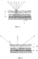
Figure 4 shows a cross-section of the layout of a multi-view autostereoscopic display. Each pixel underneath a certain lenticular lens will contribute to a specific view. All pixels underneath this lens will together contribute to a cone of views. The width of this cone is determined by the combination of several parameters: it depends on the distance D from the pixel plane to the plane of the lenticular lenses. It also depends on the lens pitch PL . -
Figure 5 is a close-up ofFigure 4 , and shows that the light emitted by a pixel of thedisplay 24 is collected by the lenticular lens closest to the pixel but also by neighbouring lenses of the lenticular arrangement. This is the origin of the occurrence of repeated cones of views. - The dependence of the anglesize of a cone, Φ, on these parameters is governed by the relation (by approximation):

- In this expression, n is the average index of refraction of the materials in between the pixel plane and the plane of the lenticular lenses (typically, n is typically in the range from 1.0 (air) to 1.6). PL is the pure horizontal pitch, D is the distance from the lens base to the pixel structure.
- Note that the smaller the angular spacing between two views, the higher the 3D effect but the lower the freedom of movement.
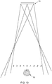
- The corresponding views produced in each of the cones are equal. This effect is schematically shown in
Figure 6 for a 9-view system (i.e. 9 views in each cone). - For an acceptable compromise between 3D effect and resolution penalty, the total number of views is limited to typically 9 or 15. These views have an angular width of typically 1°-2°. The views and the cones have the property that they are periodic. If the user walks around the display he will cross the boundaries between adjacent viewing cones. In a certain region the images in both eyes will not properly match, as for the viewer shown to the right in
Figure 6 . In the case of e.g. a 9-view system the left eye will receive e.g. the 9th image and the right eye will receive e.g. the 1st image. First of all, the left and right images are reversed, which means that the image is pseudoscopic. Secondly, and more severe, there is a very large disparity between the images. This is referred to as "super pseudoscopic" viewing. As the viewer moves across the cone boundaries very annoying discontinuous jumps are observed. - Only a viewer located entirely within a certain cone (for example the viewer to the left in
Figure 6 ) will experience a 3D effect since the views that are directed towards his left and right eye then slightly differ (e.g. views - The invention uses a viewer tracking system to track at least the position of the viewer (and thereby derive the distance from the display screen) and optionally also the speed of movement of the viewer, particularly in a lateral direction.
- The system of the invention is shown in schematic form in
Figure 7 . - The
autostereoscopic display 70 is designed to display a plurality of views in repeating image cones (for example as shown inFigure 6 ). -
Image data 72 is received. This may comprise two-view image data, in which case the display can be driven in a two-view mode. Alternatively, additional views can be interpolated by image processing techniques. - Preferably, however, the image data is provided in the form of a number of different views corresponding to the number of views per viewing cone which the
display 70 is designed for. - A
viewer tracking system 74 is provided. This is able to determine at least the distance d of theviewer 76 from the display panel, but optionally also the viewer speed of movement v, at least the component thereof in a lateral direction as shown. - The image data is processed by a
processor 78 before driving thedisplay 70 using the viewer tracking information obtained. - The system of the invention enables the number and order of the views displayed to be varied based on the position and/or moving speed of the viewer.
- The
viewer tracking system 74 can be a face or person tracking system able to measure the position and size of a face in a recorded image or video. The tracking system can derive the distance d of the viewer for example by measuring the eye distance, or by analysing the viewer's face using a stereo camera. The viewer tracking system can for example be based on an image processing face tracking algorithm, a radar system, a system based on wearable indicators, an infrared red eye generator and detector. - Any known face tracking, body tracking or distance measuring system can be used, that enables at least the distance d to the viewer to be determined.
- The physical design of the
display 70 is not altered by the system of the invention. Thus, the methods which can be implemented by the invention are based on image processing and display driving. - The system of the invention controls the allocation of images to the different viewing areas defined by the physical design of the
display 70. For example, a lower number of views can be displayed by providing identical image content to two viewing areas- which would have different images applied if the maximum number of views were to be displayed. - In general, lowering the number of views displayed by a certain display design increases the sharpness of a 3D image, at the cost of freedom of movement and possible number of viewers. By tracking the user of a display and in particular the distance of a viewer, the optimal number of different images for the user can be determined.
- The cone width WC of an autostereoscopic display depends on the optics and the viewing distance DV for which the display is designed. The optics define the angle size of the cone as explained above. The width of the viewing cone is given by:

- This relation links the anglesize to the actual width at viewing distance Dv.
- The system of the invention can be controlled to implement various possible methods, described below.
- A first example is explained with reference to
Figures 8 and9 , in which the closer the viewer is to the display, the lower the number of images presented by the display. -
Figure 8 shows a viewer close to the display, and the display is configured to display only two views (right R and left L). To display two views, the two views are repeated in the various viewing areas within each cone. For example if the display optics are designed as a nine-view system, five/four left views and four/five right views can be displayed. This does not increase the resolution of the views, but it does reduce cross talk and thereby reduce image blurring. - The display can be switched to the two view mode when the viewing distance is lower than a threshold. For example, mode switching can take place if the viewing distance d is such that the eye separation is greater than 0.25 times the cone width at that viewing distance. If the ratio becomes smaller than 0.25 the display can be switched to an autostereoscopic mode with more than two views. The threshold of 0.25 can be different, for example between 0.2 and 0.3 or even between 0.1 and ,0.5.
- Based on the threshold of 0.25, the following relationships hold:


- A fixed eye separation can be assumed, for example 6cm. In this case, the cone width threshold WC is 24cm. This threshold may be anywhere between 15 and 40cm for example.
-
Figure 9 shows the display with a viewer further from the display, and thereby operated in the multiple view mode. Nine different views (numbered -4 to +4) are shown. - The system can also be used to detect the speed of movement of the viewer. When the viewer moves at a speed higher than a tracker can follow, the display can again switch to a single view mode (a 2D mode) so that it is prevented that the user will see a left-right inverted image when cone boundaries are passed.
- Another use of speed tracking is to change the order of viewpoints across the cone width, to a non-linear order, when the movement is faster than the a tracker can follow. This can be carried out to soften the visibility of cone transitions. For example a view order (for a nine view system) within the cones could be -1 -3 -2 -1 0 1 2 3 1 instead of -4 -3 -2 -1 0 1 2 3 4 as shown in
Figure 9 . - In this way, the possibility of seeing
views 4 and -4 is avoided at the cone boundary. Instead of this nine view difference, the largest difference in view number is 2 (views views 1 and -1 at the cone boundary.. - Thus the largest difference in view number of adjacently displayed views can be set to be 2.
- The display can be designed so that the viewing distance compensation is most effective. For example, the display can be designed such that at a default viewing distance (for which the display is designed), the cone width is smaller than 4 times the eye distance E, for example less than 30cm. The cone width can be designed to be smaller than 3 times the eye distance E, which will correspond to around 20cm. The default viewing distance can for example be equal to 2 times the display width.
- In this way, the distance system will switch to a two-view mode when the viewer is at the designed distance from the display, and will only give more views when the viewer is further away. The default distance is thus for a single close up view, using the display as a monitor, but the display can be used at a larger viewing distance by multiple users
- A further way of using the system of the invention is explained with reference to
Figure 10 . - In this case, there are more than two views but less than the maximum possible number (nine in the example shown). The amount of visible crosstalk is reduced by setting the views within a cone which are not visible to the viewer (even if they move slightly) to be the same as the views which are visible to the viewer. In this way, a first set of views is displayed in only one viewing area each (views 1, 0 and -1) and a second set of views (
views 2 and -2) are displayed at least in two adjacent viewing areas each. - In the example shown, the central views are displayed once, and the lateral edge views are displayed three times.
- However, this depends on the position of the viewer. For example the images directed to the viewer (but allowing a limited range of movement) can all be presented once, and the remaining viewing locations can be provided with identical views. This will typically give two or three images displayed once (three in the example shown - 1, 0, -1) and only two other images used for all other views (2, -2).
- In this way, the images displayed within a cone are selected depending on the relative position of the viewer within the cone.
- The invention is especially applicable to monitor sized displays which can switch between a mode for multiple viewers at larger distance and a configuration where one viewer is using the display from close-by where the display will switch to the sharpest mode possible: a two-view system.
- When there are multiple viewers, the viewer tracking system can look for the closest viewer to the display, and use this closest viewer to judge whether to switch display mode. Alternatively, the display can remain in multiple view mode whenever more than one viewer is detected, and only switch to the two view mode when there is a single viewer being tracked, and when that single viewer is close to the display panel.
- The invention can be used in barrier or lenticular systems, or indeed other optical systems, for example using microlenses.
- There may also be a manual override to enable the user to select between the two view and multiple view modes.
- The invention has been described in connection with an LCD display, but it can be applied to other display technologies, such as OLED displays.
- If the input data to the system includes only two views (rather than 2D and depth information, or multiview images), the system can include stereo to multiview conversion.
- When the input data to the system is 2D and depth information, the depth information can be scaled when the display is switched to a low number of views or to the stereo (2 view) mode. For example the generated disparity differences can be made at least 20 % larger to increase the depth effect.
- When the input data to the system is multiview images, there is a choice of which pair of views to use for the stereo (2 view) mode. Views which can for example be chosen which are further apart than in normal configuration. For example, views 0 and 1 would normally projected to the left and right. Instead, views 0 and 2, or 0 and 3 could be selected. Even views -3 and 3 could be used. These are options because the crosstalk in the views is no longer a limiting factor.
- Other variations to the disclosed embodiments can be understood and effected by those skilled in the art in practicing the claimed invention, from a study of the drawings, the disclosure, and the appended claims. In the claims, the word "comprising" does not exclude other elements or steps, and the indefinite article "a" or "an" does not exclude a plurality. Any reference signs in the claims should not be construed as limiting the scope. The scope of the invention is given by the appended claims.
Claims (10)
- An autostereoscopic display device (70, 74, 78) comprising:a pixellated display panel (3);an imaging arrangement (9) for directing the light associated with different display pixels of the display panel to different directions, such that at least three viewing areas are defined to which different images can be displayed simultaneously, wherein the viewing areas are formed in display output viewing cones, each having a cone width, wherein the viewing cones repeat across a field of view;a viewer tracking system (74) for tracking a viewer and determining a position of a viewer with respect to the display panel;a processor (78) for processing image content to adjust the number of views and to drive the display panel, wherein the processor drives the display panel to display different numbers of views within each viewing cone which is dependent on at least the distance of the viewer from the display panel,wherein for a first viewing distance below a distance threshold, a total of two views are displayed, and for a second, greater, viewing distance, a second, greater, number of views is displayed, wherein the distance threshold is such that the cone width at that distance is in the range 13 cm to 40cm.
- A device as claimed in claim 1, wherein the processor is adapted to derive a speed of movement of the viewer, and wherein if the speed exceeds a first threshold, the number of different views is set to 1.
- A device as claimed in any preceding claim, wherein the processor is adapted to derive a speed of movement of the viewer, and wherein if the speed exceeds a second threshold, the ordering of the different views is changed.
- A device as claimed in any preceding claim, wherein within each viewing cone there is a plurality of viewing areas to which different images can be displayed simultaneously, and wherein a first set of views are each displayed in only one viewing area and a second set of views are each displayed at least in two adjacent viewing areas.
- A device as claimed in any preceding claim, wherein the cone width at a viewing distance equal to two times a display panel width is less than 30cm.
- A method of driving an autostereoscopic display device (70, 74, 78) comprising:directing the light associated with different display pixels of a pixellated display panel (3) to different directions, such that at least three viewing areas are defined to which different images can be displayed simultaneously, wherein the viewing areas are formed in display output viewing cones, wherein the viewing cones repeat across a field of view;tracking a viewer and determining a position of the viewer with respect to the display panel;processing image content and driving the display panel to display a number of different views within each viewing cone which is dependent on at least the distance of the viewer from the display panel,wherein for a first viewing distance below a distance threshold, a total of two views are displayed, and for a second, greater, viewing distance, a second, greater, number of views is displayed, wherein the distance threshold is such that the cone width at that distance is in the range 13 cm to 40cm.
- A method as claimed in claim 6 comprising deriving a speed of movement of the viewer, wherein if the speed exceeds a first threshold, the number of different views is set to 1.
- A method as claimed in claim 6 or 7 comprising deriving a speed of movement of the viewer, wherein if the speed exceeds a second threshold, the ordering of the different views is changed.
- A method as claimed in any one of claim 6 to 8, wherein within each cone there is a plurality of viewing areas to which different images can be displayed simultaneously,
wherein the method comprises displaying a first set of views each in only one viewing area and displaying a second set of views each in at least two adjacent viewing areas. - A computer program adapted to implement the method of any one of claims 6 to 9 when said program is run on a computer.
Applications Claiming Priority (2)
| Application Number | Priority Date | Filing Date | Title |
|---|---|---|---|
| GB1202691.0A GB2499426A (en) | 2012-02-16 | 2012-02-16 | Autostereoscopic display device with viewer tracking system |
| PCT/EP2013/052599 WO2013120785A2 (en) | 2012-02-16 | 2013-02-08 | Autostereoscopic display device and drive method |
Publications (2)
| Publication Number | Publication Date |
|---|---|
| EP2815577A2 EP2815577A2 (en) | 2014-12-24 |
| EP2815577B1 true EP2815577B1 (en) | 2019-07-03 |
Family
ID=45939739
Family Applications (1)
| Application Number | Title | Priority Date | Filing Date |
|---|---|---|---|
| EP13709048.6A Active EP2815577B1 (en) | 2012-02-16 | 2013-02-08 | Autostereoscopic display device and drive method |
Country Status (7)
| Country | Link |
|---|---|
| US (1) | US9479767B2 (en) |
| EP (1) | EP2815577B1 (en) |
| JP (1) | JP6242818B2 (en) |
| KR (1) | KR20150004323A (en) |
| CN (1) | CN104272733B (en) |
| GB (1) | GB2499426A (en) |
| WO (1) | WO2013120785A2 (en) |
Families Citing this family (29)
| Publication number | Priority date | Publication date | Assignee | Title |
|---|---|---|---|---|
| CN105723705B (en) * | 2013-11-20 | 2019-07-26 | 皇家飞利浦有限公司 | The generation of image for automatic stereo multi-view display |
| US10291907B2 (en) | 2014-01-23 | 2019-05-14 | Telefonaktiebolaget Lm Ericsson (Publ) | Multi-view display control for channel selection |
| DE102014205519A1 (en) * | 2014-03-25 | 2015-10-01 | Robert Bosch Gmbh | Method and apparatus for adapting a display of an autostereoscopic display for a vehicle |
| GB2527548A (en) * | 2014-06-25 | 2015-12-30 | Sharp Kk | Variable barrier pitch correction |
| US20170336626A1 (en) * | 2014-11-07 | 2017-11-23 | Sony Corporation | Display device and display control method |
| US11468639B2 (en) * | 2015-02-20 | 2022-10-11 | Microsoft Technology Licensing, Llc | Selective occlusion system for augmented reality devices |
| CN108633331A (en) * | 2015-05-05 | 2018-10-09 | 皇家飞利浦有限公司 | The generation of image for automatic stereoscopic display device |
| KR102415502B1 (en) * | 2015-08-07 | 2022-07-01 | 삼성전자주식회사 | Method and apparatus of light filed rendering for plurality of user |
| CN108432245B (en) * | 2015-12-29 | 2021-03-02 | 皇家飞利浦有限公司 | Autostereoscopic display apparatus and display method |
| CN105739707B (en) * | 2016-03-04 | 2018-10-02 | 京东方科技集团股份有限公司 | Electronic equipment, face recognition tracking and 3 D displaying method |
| FR3071625B1 (en) * | 2017-09-26 | 2019-09-27 | Alioscopy | SYSTEM AND METHOD FOR DISPLAYING A 2-POINT VIEW AUTOSTEREOSCOPIC IMAGE ON A POST-VIEW AUTOSTEREOSCOPIC DISPLAY SCREEN AND DISPLAY CONTROL METHOD THEREIN |
| US10298921B1 (en) | 2018-02-27 | 2019-05-21 | Looking Glass Factory, Inc. | Superstereoscopic display with enhanced off-angle separation |
| CN109188700B (en) * | 2018-10-30 | 2021-05-11 | 京东方科技集团股份有限公司 | Optical display system and AR/VR display device |
| EP3687168A1 (en) * | 2019-01-24 | 2020-07-29 | Ultra-D Coöperatief U.A. | Assigning view numbers to display elements of an autostereoscopic display |
| TWI683131B (en) * | 2019-03-21 | 2020-01-21 | 大陸商信泰光學(深圳)有限公司 | Optical device and illuminating module thereof |
| CN111722400B (en) | 2019-03-21 | 2022-08-16 | 信泰光学(深圳)有限公司 | Optical device and lighting module thereof |
| JP2021141423A (en) * | 2020-03-04 | 2021-09-16 | 富士フイルムビジネスイノベーション株式会社 | Display system, display control device, and program |
| US11449004B2 (en) | 2020-05-21 | 2022-09-20 | Looking Glass Factory, Inc. | System and method for holographic image display |
| WO2021243037A1 (en) | 2020-05-27 | 2021-12-02 | Looking Glass Factory, Inc. | System and method for holographic displays |
| WO2021262860A1 (en) | 2020-06-23 | 2021-12-30 | Looking Glass Factory, Inc. | System and method for holographic communication |
| WO2022086580A1 (en) * | 2020-10-21 | 2022-04-28 | Google Llc | Dynamic resolution of depth conflicts in telepresence |
| WO2022119940A1 (en) | 2020-12-01 | 2022-06-09 | Looking Glass Factory, Inc. | System and method for processing three dimensional images |
| TWI800959B (en) | 2021-10-22 | 2023-05-01 | 宏碁股份有限公司 | Eye tracking method and eye tracking device |
| NL2030186B1 (en) | 2021-12-17 | 2023-06-28 | Dimenco Holding B V | Autostereoscopic display device presenting 3d-view and 3d-sound |
| NL2030187B1 (en) | 2021-12-18 | 2023-06-28 | Dimenco Holding B V | Method and device for cancelling distortion and displacement of a displayed three dimensional image |
| NL2030325B1 (en) | 2021-12-28 | 2023-07-03 | Dimenco Holding B V | Scaling of three-dimensional content for an autostereoscopic display device |
| NL2030326B1 (en) | 2021-12-29 | 2023-07-04 | Dimenco Holding B V | Autostereoscopic display device having a remote body tracking system |
| TWI806379B (en) | 2022-01-24 | 2023-06-21 | 宏碁股份有限公司 | Feature point position detection method and electronic device |
| NL2032281B1 (en) | 2022-06-25 | 2024-01-09 | Dimenco Holding B V | Autostereoscopic display system comprising a plurality of autostereoscopic display devices |
Citations (1)
| Publication number | Priority date | Publication date | Assignee | Title |
|---|---|---|---|---|
| US20110310233A1 (en) * | 2010-06-21 | 2011-12-22 | Microsoft Corporation | Optimization of a Multi-View Display |
Family Cites Families (25)
| Publication number | Priority date | Publication date | Assignee | Title |
|---|---|---|---|---|
| GB2297876A (en) * | 1995-02-09 | 1996-08-14 | Sharp Kk | Observer tracking autostereoscopic display |
| JP3229824B2 (en) * | 1995-11-15 | 2001-11-19 | 三洋電機株式会社 | 3D image display device |
| US7190518B1 (en) * | 1996-01-22 | 2007-03-13 | 3Ality, Inc. | Systems for and methods of three dimensional viewing |
| GB2324428A (en) * | 1997-04-17 | 1998-10-21 | Sharp Kk | Image tracking; observer tracking stereoscopic display |
| JP2000098299A (en) * | 1998-09-18 | 2000-04-07 | Sanyo Electric Co Ltd | Stereoscopic video display device |
| JP3802474B2 (en) * | 2002-10-21 | 2006-07-26 | 三洋電機株式会社 | 3D image display device |
| JP4533895B2 (en) * | 2003-09-30 | 2010-09-01 | コーニンクレッカ フィリップス エレクトロニクス エヌ ヴィ | Motion control for image rendering |
| EP1728116B1 (en) | 2004-03-12 | 2012-09-19 | Koninklijke Philips Electronics N.V. | Multiview display device |
| EP1932053A4 (en) * | 2005-09-16 | 2010-06-02 | Stereographics Corp | Method and apparatus for optimizing the viewing of a lenticular stereogram |
| JP2009077234A (en) * | 2007-09-21 | 2009-04-09 | Toshiba Corp | Apparatus, method and program for processing three-dimensional image |
| EP2246850B1 (en) * | 2008-01-31 | 2012-12-12 | JVC KENWOOD Corporation | Method for discriminating optical disc, optical disc device and program |
| WO2009095862A1 (en) | 2008-02-01 | 2009-08-06 | Koninklijke Philips Electronics N.V. | Autostereoscopic display device |
| EP2340648B1 (en) * | 2008-10-28 | 2019-12-11 | Koninklijke Philips N.V. | A three dimensional display system |
| DE102009009443B3 (en) * | 2009-02-14 | 2010-09-23 | Fraunhofer-Gesellschaft zur Förderung der angewandten Forschung e.V. | Monitor and method for displaying autostereoscopic images |
| US20120062991A1 (en) * | 2009-05-28 | 2012-03-15 | Koninklijke Philips Electronics N.V. | Autostereoscopic display device |
| KR101615111B1 (en) | 2009-06-16 | 2016-04-25 | 삼성전자주식회사 | Multi-view display device and method thereof |
| KR101057098B1 (en) * | 2009-07-10 | 2011-08-16 | (주)엔디스 | Luminance flicker control apparatus and method for wide viewing angle stereoscopic display |
| JP5356952B2 (en) * | 2009-08-31 | 2013-12-04 | レムセン イノベーション、リミティッド ライアビリティー カンパニー | Display device |
| KR101629479B1 (en) * | 2009-11-04 | 2016-06-10 | 삼성전자주식회사 | High density multi-view display system and method based on the active sub-pixel rendering |
| US8633972B2 (en) * | 2010-03-03 | 2014-01-21 | Fraunhofer-Geselschaft zur Foerderung der angewandten Forschung e.V. | Method for displaying image information and autostereoscopic screen |
| JP2011205358A (en) * | 2010-03-25 | 2011-10-13 | Fujifilm Corp | Head-mounted display device |
| TWI462568B (en) * | 2010-10-29 | 2014-11-21 | Au Optronics Corp | Image display method of stereo display apparatus |
| WO2012057774A1 (en) * | 2010-10-29 | 2012-05-03 | Hewlett-Packard Development Company, L.P. | A three-dimensional image based on a distance of a viewer |
| JP5978695B2 (en) * | 2011-05-27 | 2016-08-24 | 株式会社Jvcケンウッド | Autostereoscopic display device and viewpoint adjustment method |
| EP2805517A1 (en) * | 2012-01-17 | 2014-11-26 | Sony Ericsson Mobile Communications AB | Portable electronic equipment and method of controlling an autostereoscopic display |
-
2012
- 2012-02-16 GB GB1202691.0A patent/GB2499426A/en not_active Withdrawn
-
2013
- 2013-02-08 US US14/379,081 patent/US9479767B2/en active Active
- 2013-02-08 KR KR20147025718A patent/KR20150004323A/en not_active Application Discontinuation
- 2013-02-08 JP JP2014556996A patent/JP6242818B2/en active Active
- 2013-02-08 CN CN201380019924.XA patent/CN104272733B/en active Active
- 2013-02-08 EP EP13709048.6A patent/EP2815577B1/en active Active
- 2013-02-08 WO PCT/EP2013/052599 patent/WO2013120785A2/en active Application Filing
Patent Citations (1)
| Publication number | Priority date | Publication date | Assignee | Title |
|---|---|---|---|---|
| US20110310233A1 (en) * | 2010-06-21 | 2011-12-22 | Microsoft Corporation | Optimization of a Multi-View Display |
Also Published As
| Publication number | Publication date |
|---|---|
| GB201202691D0 (en) | 2012-04-04 |
| WO2013120785A3 (en) | 2013-10-24 |
| CN104272733A (en) | 2015-01-07 |
| WO2013120785A2 (en) | 2013-08-22 |
| US20150281682A1 (en) | 2015-10-01 |
| US9479767B2 (en) | 2016-10-25 |
| KR20150004323A (en) | 2015-01-12 |
| EP2815577A2 (en) | 2014-12-24 |
| JP6242818B2 (en) | 2017-12-06 |
| JP2015515165A (en) | 2015-05-21 |
| CN104272733B (en) | 2017-03-08 |
| GB2499426A (en) | 2013-08-21 |
Similar Documents
| Publication | Publication Date | Title |
|---|---|---|
| EP2815577B1 (en) | Autostereoscopic display device and drive method | |
| JP5710330B2 (en) | Display device | |
| US20120092339A1 (en) | Multi-view autostereoscopic display device | |
| EP3017335B1 (en) | Auto-stereoscopic display device with a striped backlight and two lenticular lens arrays | |
| KR100878130B1 (en) | Autostereoscopic image display apparatus with user control and method therefor | |
| JP2010524309A (en) | Method and configuration for three-dimensional display | |
| KR102197536B1 (en) | 3d display device for reducing moving flicker | |
| JP5762998B2 (en) | Display device and electronic device | |
| JP2010282090A (en) | Stereoscopic image display device | |
| US20150237334A1 (en) | Stereoscopic display device | |
| KR20160058327A (en) | Three dimensional image display device | |
| KR20150055322A (en) | multi view image display apparatus and multi view image display method thereof | |
| EP3225025B1 (en) | Display device and method of controlling the same | |
| US20180217391A1 (en) | 3D Display Device and Driving Method Thereof | |
| US10715792B2 (en) | Display device and method of controlling the same | |
| KR101908511B1 (en) | Stereoscopic Image Display Device and Method for Driving the Same | |
| KR101852819B1 (en) | An apparatus and a method for displaying a 3-dimensional image | |
| KR102279816B1 (en) | Autostereoscopic 3d display device | |
| KR101911776B1 (en) | Three-dimensional displaying device and method thereof | |
| KR101697591B1 (en) | Stereoscopic 3d display device and method of driving the same | |
| KR101190050B1 (en) | 3-dimensional displaying apparatus and driving method thereof | |
| KR101239230B1 (en) | 3-dimensional displaying apparatus and driving method thereof | |
| KR102279277B1 (en) | Stereoscopic display device and method of displaying 3d image having good quality to multi-user |
Legal Events
| Date | Code | Title | Description |
|---|---|---|---|
| PUAI | Public reference made under article 153(3) epc to a published international application that has entered the european phase |
Free format text: ORIGINAL CODE: 0009012 |
|
| 17P | Request for examination filed |
Effective date: 20140915 |
|
| AK | Designated contracting states |
Kind code of ref document: A2 Designated state(s): AL AT BE BG CH CY CZ DE DK EE ES FI FR GB GR HR HU IE IS IT LI LT LU LV MC MK MT NL NO PL PT RO RS SE SI SK SM TR |
|
| AX | Request for extension of the european patent |
Extension state: BA ME |
|
| DAX | Request for extension of the european patent (deleted) | ||
| STAA | Information on the status of an ep patent application or granted ep patent |
Free format text: STATUS: EXAMINATION IS IN PROGRESS |
|
| 17Q | First examination report despatched |
Effective date: 20170407 |
|
| REG | Reference to a national code |
Ref country code: DE Ref legal event code: R079 Ref document number: 602013057354 Country of ref document: DE Free format text: PREVIOUS MAIN CLASS: H04N0013040000 Ipc: H04N0013305000 |
|
| RIC1 | Information provided on ipc code assigned before grant |
Ipc: H04N 13/398 20180101ALI20181220BHEP Ipc: H04N 13/351 20180101ALI20181220BHEP Ipc: H04N 13/376 20180101ALI20181220BHEP Ipc: H04N 13/117 20180101ALI20181220BHEP Ipc: H04N 13/305 20180101AFI20181220BHEP Ipc: H04N 13/359 20180101ALI20181220BHEP Ipc: H04N 13/373 20180101ALI20181220BHEP Ipc: H04N 13/368 20180101ALI20181220BHEP |
|
| GRAP | Despatch of communication of intention to grant a patent |
Free format text: ORIGINAL CODE: EPIDOSNIGR1 |
|
| STAA | Information on the status of an ep patent application or granted ep patent |
Free format text: STATUS: GRANT OF PATENT IS INTENDED |
|
| INTG | Intention to grant announced |
Effective date: 20190206 |
|
| GRAS | Grant fee paid |
Free format text: ORIGINAL CODE: EPIDOSNIGR3 |
|
| GRAA | (expected) grant |
Free format text: ORIGINAL CODE: 0009210 |
|
| STAA | Information on the status of an ep patent application or granted ep patent |
Free format text: STATUS: THE PATENT HAS BEEN GRANTED |
|
| AK | Designated contracting states |
Kind code of ref document: B1 Designated state(s): AL AT BE BG CH CY CZ DE DK EE ES FI FR GB GR HR HU IE IS IT LI LT LU LV MC MK MT NL NO PL PT RO RS SE SI SK SM TR |
|
| REG | Reference to a national code |
Ref country code: GB Ref legal event code: FG4D |
|
| REG | Reference to a national code |
Ref country code: CH Ref legal event code: EP Ref country code: AT Ref legal event code: REF Ref document number: 1152419 Country of ref document: AT Kind code of ref document: T Effective date: 20190715 |
|
| REG | Reference to a national code |
Ref country code: IE Ref legal event code: FG4D |
|
| REG | Reference to a national code |
Ref country code: DE Ref legal event code: R096 Ref document number: 602013057354 Country of ref document: DE |
|
| REG | Reference to a national code |
Ref country code: NL Ref legal event code: MP Effective date: 20190703 |
|
| REG | Reference to a national code |
Ref country code: LT Ref legal event code: MG4D |
|
| REG | Reference to a national code |
Ref country code: AT Ref legal event code: MK05 Ref document number: 1152419 Country of ref document: AT Kind code of ref document: T Effective date: 20190703 |
|
| PG25 | Lapsed in a contracting state [announced via postgrant information from national office to epo] |
Ref country code: CZ Free format text: LAPSE BECAUSE OF FAILURE TO SUBMIT A TRANSLATION OF THE DESCRIPTION OR TO PAY THE FEE WITHIN THE PRESCRIBED TIME-LIMIT Effective date: 20190703 Ref country code: BG Free format text: LAPSE BECAUSE OF FAILURE TO SUBMIT A TRANSLATION OF THE DESCRIPTION OR TO PAY THE FEE WITHIN THE PRESCRIBED TIME-LIMIT Effective date: 20191003 Ref country code: HR Free format text: LAPSE BECAUSE OF FAILURE TO SUBMIT A TRANSLATION OF THE DESCRIPTION OR TO PAY THE FEE WITHIN THE PRESCRIBED TIME-LIMIT Effective date: 20190703 Ref country code: PT Free format text: LAPSE BECAUSE OF FAILURE TO SUBMIT A TRANSLATION OF THE DESCRIPTION OR TO PAY THE FEE WITHIN THE PRESCRIBED TIME-LIMIT Effective date: 20191104 Ref country code: NL Free format text: LAPSE BECAUSE OF FAILURE TO SUBMIT A TRANSLATION OF THE DESCRIPTION OR TO PAY THE FEE WITHIN THE PRESCRIBED TIME-LIMIT Effective date: 20190703 Ref country code: AT Free format text: LAPSE BECAUSE OF FAILURE TO SUBMIT A TRANSLATION OF THE DESCRIPTION OR TO PAY THE FEE WITHIN THE PRESCRIBED TIME-LIMIT Effective date: 20190703 Ref country code: NO Free format text: LAPSE BECAUSE OF FAILURE TO SUBMIT A TRANSLATION OF THE DESCRIPTION OR TO PAY THE FEE WITHIN THE PRESCRIBED TIME-LIMIT Effective date: 20191003 Ref country code: LT Free format text: LAPSE BECAUSE OF FAILURE TO SUBMIT A TRANSLATION OF THE DESCRIPTION OR TO PAY THE FEE WITHIN THE PRESCRIBED TIME-LIMIT Effective date: 20190703 Ref country code: FI Free format text: LAPSE BECAUSE OF FAILURE TO SUBMIT A TRANSLATION OF THE DESCRIPTION OR TO PAY THE FEE WITHIN THE PRESCRIBED TIME-LIMIT Effective date: 20190703 Ref country code: SE Free format text: LAPSE BECAUSE OF FAILURE TO SUBMIT A TRANSLATION OF THE DESCRIPTION OR TO PAY THE FEE WITHIN THE PRESCRIBED TIME-LIMIT Effective date: 20190703 |
|
| PG25 | Lapsed in a contracting state [announced via postgrant information from national office to epo] |
Ref country code: GR Free format text: LAPSE BECAUSE OF FAILURE TO SUBMIT A TRANSLATION OF THE DESCRIPTION OR TO PAY THE FEE WITHIN THE PRESCRIBED TIME-LIMIT Effective date: 20191004 Ref country code: IS Free format text: LAPSE BECAUSE OF FAILURE TO SUBMIT A TRANSLATION OF THE DESCRIPTION OR TO PAY THE FEE WITHIN THE PRESCRIBED TIME-LIMIT Effective date: 20191103 Ref country code: LV Free format text: LAPSE BECAUSE OF FAILURE TO SUBMIT A TRANSLATION OF THE DESCRIPTION OR TO PAY THE FEE WITHIN THE PRESCRIBED TIME-LIMIT Effective date: 20190703 Ref country code: RS Free format text: LAPSE BECAUSE OF FAILURE TO SUBMIT A TRANSLATION OF THE DESCRIPTION OR TO PAY THE FEE WITHIN THE PRESCRIBED TIME-LIMIT Effective date: 20190703 Ref country code: AL Free format text: LAPSE BECAUSE OF FAILURE TO SUBMIT A TRANSLATION OF THE DESCRIPTION OR TO PAY THE FEE WITHIN THE PRESCRIBED TIME-LIMIT Effective date: 20190703 Ref country code: ES Free format text: LAPSE BECAUSE OF FAILURE TO SUBMIT A TRANSLATION OF THE DESCRIPTION OR TO PAY THE FEE WITHIN THE PRESCRIBED TIME-LIMIT Effective date: 20190703 |
|
| PG25 | Lapsed in a contracting state [announced via postgrant information from national office to epo] |
Ref country code: TR Free format text: LAPSE BECAUSE OF FAILURE TO SUBMIT A TRANSLATION OF THE DESCRIPTION OR TO PAY THE FEE WITHIN THE PRESCRIBED TIME-LIMIT Effective date: 20190703 |
|
| PG25 | Lapsed in a contracting state [announced via postgrant information from national office to epo] |
Ref country code: IT Free format text: LAPSE BECAUSE OF FAILURE TO SUBMIT A TRANSLATION OF THE DESCRIPTION OR TO PAY THE FEE WITHIN THE PRESCRIBED TIME-LIMIT Effective date: 20190703 Ref country code: RO Free format text: LAPSE BECAUSE OF FAILURE TO SUBMIT A TRANSLATION OF THE DESCRIPTION OR TO PAY THE FEE WITHIN THE PRESCRIBED TIME-LIMIT Effective date: 20190703 Ref country code: EE Free format text: LAPSE BECAUSE OF FAILURE TO SUBMIT A TRANSLATION OF THE DESCRIPTION OR TO PAY THE FEE WITHIN THE PRESCRIBED TIME-LIMIT Effective date: 20190703 Ref country code: DK Free format text: LAPSE BECAUSE OF FAILURE TO SUBMIT A TRANSLATION OF THE DESCRIPTION OR TO PAY THE FEE WITHIN THE PRESCRIBED TIME-LIMIT Effective date: 20190703 Ref country code: PL Free format text: LAPSE BECAUSE OF FAILURE TO SUBMIT A TRANSLATION OF THE DESCRIPTION OR TO PAY THE FEE WITHIN THE PRESCRIBED TIME-LIMIT Effective date: 20190703 |
|
| PG25 | Lapsed in a contracting state [announced via postgrant information from national office to epo] |
Ref country code: SK Free format text: LAPSE BECAUSE OF FAILURE TO SUBMIT A TRANSLATION OF THE DESCRIPTION OR TO PAY THE FEE WITHIN THE PRESCRIBED TIME-LIMIT Effective date: 20190703 Ref country code: IS Free format text: LAPSE BECAUSE OF FAILURE TO SUBMIT A TRANSLATION OF THE DESCRIPTION OR TO PAY THE FEE WITHIN THE PRESCRIBED TIME-LIMIT Effective date: 20200224 Ref country code: SM Free format text: LAPSE BECAUSE OF FAILURE TO SUBMIT A TRANSLATION OF THE DESCRIPTION OR TO PAY THE FEE WITHIN THE PRESCRIBED TIME-LIMIT Effective date: 20190703 |
|
| REG | Reference to a national code |
Ref country code: DE Ref legal event code: R097 Ref document number: 602013057354 Country of ref document: DE |
|
| PLBE | No opposition filed within time limit |
Free format text: ORIGINAL CODE: 0009261 |
|
| STAA | Information on the status of an ep patent application or granted ep patent |
Free format text: STATUS: NO OPPOSITION FILED WITHIN TIME LIMIT |
|
| PG2D | Information on lapse in contracting state deleted |
Ref country code: IS |
|
| 26N | No opposition filed |
Effective date: 20200603 |
|
| PG25 | Lapsed in a contracting state [announced via postgrant information from national office to epo] |
Ref country code: SI Free format text: LAPSE BECAUSE OF FAILURE TO SUBMIT A TRANSLATION OF THE DESCRIPTION OR TO PAY THE FEE WITHIN THE PRESCRIBED TIME-LIMIT Effective date: 20190703 |
|
| REG | Reference to a national code |
Ref country code: CH Ref legal event code: PL |
|
| PG25 | Lapsed in a contracting state [announced via postgrant information from national office to epo] |
Ref country code: LU Free format text: LAPSE BECAUSE OF NON-PAYMENT OF DUE FEES Effective date: 20200208 Ref country code: MC Free format text: LAPSE BECAUSE OF FAILURE TO SUBMIT A TRANSLATION OF THE DESCRIPTION OR TO PAY THE FEE WITHIN THE PRESCRIBED TIME-LIMIT Effective date: 20190703 |
|
| PG25 | Lapsed in a contracting state [announced via postgrant information from national office to epo] |
Ref country code: CH Free format text: LAPSE BECAUSE OF NON-PAYMENT OF DUE FEES Effective date: 20200229 Ref country code: LI Free format text: LAPSE BECAUSE OF NON-PAYMENT OF DUE FEES Effective date: 20200229 |
|
| PG25 | Lapsed in a contracting state [announced via postgrant information from national office to epo] |
Ref country code: IE Free format text: LAPSE BECAUSE OF NON-PAYMENT OF DUE FEES Effective date: 20200208 |
|
| PG25 | Lapsed in a contracting state [announced via postgrant information from national office to epo] |
Ref country code: MT Free format text: LAPSE BECAUSE OF FAILURE TO SUBMIT A TRANSLATION OF THE DESCRIPTION OR TO PAY THE FEE WITHIN THE PRESCRIBED TIME-LIMIT Effective date: 20190703 Ref country code: CY Free format text: LAPSE BECAUSE OF FAILURE TO SUBMIT A TRANSLATION OF THE DESCRIPTION OR TO PAY THE FEE WITHIN THE PRESCRIBED TIME-LIMIT Effective date: 20190703 |
|
| PG25 | Lapsed in a contracting state [announced via postgrant information from national office to epo] |
Ref country code: MK Free format text: LAPSE BECAUSE OF FAILURE TO SUBMIT A TRANSLATION OF THE DESCRIPTION OR TO PAY THE FEE WITHIN THE PRESCRIBED TIME-LIMIT Effective date: 20190703 |
|
| REG | Reference to a national code |
Ref country code: DE Ref legal event code: R081 Ref document number: 602013057354 Country of ref document: DE Owner name: DIMENCO HOLDING B.V., NL Free format text: FORMER OWNER: DIMENCO B.V., VELDHOVEN, NL |
|
| REG | Reference to a national code |
Ref country code: BE Ref legal event code: HC Owner name: DIMENCO HOLDING B.V.; NL Free format text: DETAILS ASSIGNMENT: CHANGE OF OWNER(S), CHANGE OF OWNER(S) NAME; FORMER OWNER NAME: DIMENCO B.V. Effective date: 20221122 |
|
| PGFP | Annual fee paid to national office [announced via postgrant information from national office to epo] |
Ref country code: DE Payment date: 20221213 Year of fee payment: 11 Ref country code: BE Payment date: 20230117 Year of fee payment: 11 |
|
| P01 | Opt-out of the competence of the unified patent court (upc) registered |
Effective date: 20230525 |
|
| PGFP | Annual fee paid to national office [announced via postgrant information from national office to epo] |
Ref country code: GB Payment date: 20231221 Year of fee payment: 12 |
|
| PGFP | Annual fee paid to national office [announced via postgrant information from national office to epo] |
Ref country code: FR Payment date: 20231212 Year of fee payment: 12 |