EP2815498B1 - Device for recovering and converting heat energy into electrical energy - Google Patents
Device for recovering and converting heat energy into electrical energy Download PDFInfo
- Publication number
- EP2815498B1 EP2815498B1 EP13705750.1A EP13705750A EP2815498B1 EP 2815498 B1 EP2815498 B1 EP 2815498B1 EP 13705750 A EP13705750 A EP 13705750A EP 2815498 B1 EP2815498 B1 EP 2815498B1
- Authority
- EP
- European Patent Office
- Prior art keywords
- cavity
- recovering
- electrical energy
- converting heat
- heat energy
- Prior art date
- Legal status (The legal status is an assumption and is not a legal conclusion. Google has not performed a legal analysis and makes no representation as to the accuracy of the status listed.)
- Not-in-force
Links
- 239000012530 fluid Substances 0.000 claims description 35
- 239000000463 material Substances 0.000 claims description 32
- 239000007788 liquid Substances 0.000 claims description 29
- 239000012528 membrane Substances 0.000 claims description 17
- 238000009835 boiling Methods 0.000 claims description 9
- 238000009736 wetting Methods 0.000 claims description 7
- 239000011810 insulating material Substances 0.000 claims description 6
- 230000004907 flux Effects 0.000 claims description 3
- 239000004020 conductor Substances 0.000 claims description 2
- 238000009834 vaporization Methods 0.000 description 20
- 230000008016 vaporization Effects 0.000 description 20
- 238000009833 condensation Methods 0.000 description 15
- 230000005494 condensation Effects 0.000 description 15
- XLYOFNOQVPJJNP-UHFFFAOYSA-N water Substances O XLYOFNOQVPJJNP-UHFFFAOYSA-N 0.000 description 10
- 238000006243 chemical reaction Methods 0.000 description 9
- 238000006073 displacement reaction Methods 0.000 description 9
- 238000011084 recovery Methods 0.000 description 9
- 238000009826 distribution Methods 0.000 description 6
- 230000000694 effects Effects 0.000 description 6
- VYPSYNLAJGMNEJ-UHFFFAOYSA-N Silicium dioxide Chemical compound O=[Si]=O VYPSYNLAJGMNEJ-UHFFFAOYSA-N 0.000 description 5
- 230000005484 gravity Effects 0.000 description 4
- OKTJSMMVPCPJKN-UHFFFAOYSA-N Carbon Chemical compound [C] OKTJSMMVPCPJKN-UHFFFAOYSA-N 0.000 description 3
- 230000005611 electricity Effects 0.000 description 3
- 239000011521 glass Substances 0.000 description 3
- 229910002804 graphite Inorganic materials 0.000 description 3
- 239000010439 graphite Substances 0.000 description 3
- 230000002209 hydrophobic effect Effects 0.000 description 3
- 239000012071 phase Substances 0.000 description 3
- 238000001020 plasma etching Methods 0.000 description 3
- 239000011347 resin Substances 0.000 description 3
- 229920005989 resin Polymers 0.000 description 3
- 229910052814 silicon oxide Inorganic materials 0.000 description 3
- 239000002904 solvent Substances 0.000 description 3
- 238000003860 storage Methods 0.000 description 3
- 239000002470 thermal conductor Substances 0.000 description 3
- RYGMFSIKBFXOCR-UHFFFAOYSA-N Copper Chemical compound [Cu] RYGMFSIKBFXOCR-UHFFFAOYSA-N 0.000 description 2
- LFQSCWFLJHTTHZ-UHFFFAOYSA-N Ethanol Chemical compound CCO LFQSCWFLJHTTHZ-UHFFFAOYSA-N 0.000 description 2
- MCMNRKCIXSYSNV-UHFFFAOYSA-N Zirconium dioxide Chemical compound O=[Zr]=O MCMNRKCIXSYSNV-UHFFFAOYSA-N 0.000 description 2
- 229910052782 aluminium Inorganic materials 0.000 description 2
- XAGFODPZIPBFFR-UHFFFAOYSA-N aluminium Chemical compound [Al] XAGFODPZIPBFFR-UHFFFAOYSA-N 0.000 description 2
- 239000000919 ceramic Substances 0.000 description 2
- 238000005229 chemical vapour deposition Methods 0.000 description 2
- 125000004122 cyclic group Chemical group 0.000 description 2
- 238000000151 deposition Methods 0.000 description 2
- -1 graphite fluorides Chemical class 0.000 description 2
- 230000008018 melting Effects 0.000 description 2
- 238000002844 melting Methods 0.000 description 2
- 229910052751 metal Inorganic materials 0.000 description 2
- 239000002184 metal Substances 0.000 description 2
- 238000000034 method Methods 0.000 description 2
- 238000004377 microelectronic Methods 0.000 description 2
- 239000002114 nanocomposite Substances 0.000 description 2
- 230000010287 polarization Effects 0.000 description 2
- 229920000642 polymer Polymers 0.000 description 2
- 229910001220 stainless steel Inorganic materials 0.000 description 2
- 239000010935 stainless steel Substances 0.000 description 2
- 206010053317 Hydrophobia Diseases 0.000 description 1
- 241001080024 Telles Species 0.000 description 1
- 230000006978 adaptation Effects 0.000 description 1
- HIGRAKVNKLCVCA-UHFFFAOYSA-N alumine Chemical compound C1=CC=[Al]C=C1 HIGRAKVNKLCVCA-UHFFFAOYSA-N 0.000 description 1
- 239000004411 aluminium Substances 0.000 description 1
- PNEYBMLMFCGWSK-UHFFFAOYSA-N aluminium oxide Inorganic materials [O-2].[O-2].[O-2].[Al+3].[Al+3] PNEYBMLMFCGWSK-UHFFFAOYSA-N 0.000 description 1
- 239000012080 ambient air Substances 0.000 description 1
- 238000005219 brazing Methods 0.000 description 1
- 239000002041 carbon nanotube Substances 0.000 description 1
- 229910021393 carbon nanotube Inorganic materials 0.000 description 1
- 230000000295 complement effect Effects 0.000 description 1
- 238000001816 cooling Methods 0.000 description 1
- 229910052802 copper Inorganic materials 0.000 description 1
- 239000010949 copper Substances 0.000 description 1
- 230000008878 coupling Effects 0.000 description 1
- 238000010168 coupling process Methods 0.000 description 1
- 238000005859 coupling reaction Methods 0.000 description 1
- 230000003247 decreasing effect Effects 0.000 description 1
- 238000001704 evaporation Methods 0.000 description 1
- 230000008020 evaporation Effects 0.000 description 1
- 230000005660 hydrophilic surface Effects 0.000 description 1
- 230000005661 hydrophobic surface Effects 0.000 description 1
- 238000001459 lithography Methods 0.000 description 1
- 238000003754 machining Methods 0.000 description 1
- 239000011159 matrix material Substances 0.000 description 1
- 239000000203 mixture Substances 0.000 description 1
- 239000002086 nanomaterial Substances 0.000 description 1
- 239000002071 nanotube Substances 0.000 description 1
- 239000002245 particle Substances 0.000 description 1
- 230000000737 periodic effect Effects 0.000 description 1
- 229920000334 poly[3-(3'-N,N,N-triethylamino-1-propyloxy)-4-methylthiophene-2,5-diyl hydrochloride] polymer Polymers 0.000 description 1
- 230000002250 progressing effect Effects 0.000 description 1
- 239000000377 silicon dioxide Substances 0.000 description 1
- 230000001131 transforming effect Effects 0.000 description 1
- 239000012808 vapor phase Substances 0.000 description 1
Images


Classifications
-
- H—ELECTRICITY
- H02—GENERATION; CONVERSION OR DISTRIBUTION OF ELECTRIC POWER
- H02N—ELECTRIC MACHINES NOT OTHERWISE PROVIDED FOR
- H02N2/00—Electric machines in general using piezoelectric effect, electrostriction or magnetostriction
- H02N2/18—Electric machines in general using piezoelectric effect, electrostriction or magnetostriction producing electrical output from mechanical input, e.g. generators
- H02N2/185—Electric machines in general using piezoelectric effect, electrostriction or magnetostriction producing electrical output from mechanical input, e.g. generators using fluid streams
-
- H—ELECTRICITY
- H02—GENERATION; CONVERSION OR DISTRIBUTION OF ELECTRIC POWER
- H02N—ELECTRIC MACHINES NOT OTHERWISE PROVIDED FOR
- H02N2/00—Electric machines in general using piezoelectric effect, electrostriction or magnetostriction
- H02N2/18—Electric machines in general using piezoelectric effect, electrostriction or magnetostriction producing electrical output from mechanical input, e.g. generators
-
- H—ELECTRICITY
- H10—SEMICONDUCTOR DEVICES; ELECTRIC SOLID-STATE DEVICES NOT OTHERWISE PROVIDED FOR
- H10N—ELECTRIC SOLID-STATE DEVICES NOT OTHERWISE PROVIDED FOR
- H10N30/00—Piezoelectric or electrostrictive devices
-
- H—ELECTRICITY
- H10—SEMICONDUCTOR DEVICES; ELECTRIC SOLID-STATE DEVICES NOT OTHERWISE PROVIDED FOR
- H10N—ELECTRIC SOLID-STATE DEVICES NOT OTHERWISE PROVIDED FOR
- H10N30/00—Piezoelectric or electrostrictive devices
- H10N30/80—Constructional details
- H10N30/87—Electrodes or interconnections, e.g. leads or terminals
Definitions
- the present invention relates to a device for recovering and converting thermal energy into electrical energy by using the phase change of a fluid.
- This device has the disadvantage of requiring to orient the second wall below the first wall according to the forces of gravity to ensure the fall of the condensed drops.
- a device for recovering and converting thermal energy into electrical energy comprising a first cavity whose wall is intended to be in contact with a hot source, a second cavity whose wall is intended to in contact with a cold source, a piezoelectric material disposed in at least one of the cavities, a primary channel connecting the first and second cavities and at least one secondary channel connecting the first and second cavities, the configuration of the primary channel being such it ensures a circulation of drops of liquids from the second cavity to the first cavity.
- the primary channel may comprise an inner surface having a surface energy gradient oriented so as to cause the displacement of the drops of liquid from the second cavity to the first cavity.
- the surface comprises sections of different hydrophobies, the sections being less and less hydrophobic in the direction of the first cavity.
- the main channel has an increasing passage section towards the first cavity and a surface having at least one a property of hydrophobicity.
- the surface may have a decreasing hydrophobicity in the direction of the first cavity.
- the device comprises a condensation chamber and a vaporization chamber connected by a channel ensuring the transfer of drops of liquid from the condensation chamber to the vaporization chamber without using the gravity forces.
- At least one of the chambers comprises a membrane of piezoelectric material.
- the displacement means are formed by the inner surface of the primary channel having a surface energy gradient oriented so that the drops of liquid move from the second cavity to the first cavity.
- the surface energy gradient is obtained by at least a first and a second surface section successively arranged in this order between the second cavity and the first cavity, each of said sections having wettability properties vis-à-vis the fluid, the wettability of the second section being greater than that of the first section.
- the wettability properties can be obtained from a layer of a material having said wettability properties and / or by structuring at least one section of the inner surface.
- the primary channel has a section of increasing passage from the second cavity to the first cavity.
- At least a portion of the inner surface of the primary channel on the side of the second cavity may have properties of low wettability vis-à-vis the fluid.
- the displacement means are of the electrostatic type, for example implement the phenomenon of electrowetting.
- the primary channel may have a flared shape or comprise at least two successive sections having different passage sections, the passage sections increasing from the second cavity to the first cavity.
- the passage section of the secondary channel may be such that it prevents the passage of liquid drops.
- the section of the secondary channel is preferably less than 0.1 times the capillary length.
- the secondary channel opens into the second cavity near an end of the primary channel opening into said second cavity.
- the device for recovering and converting thermal energy into electrical energy may advantageously comprise at least a first and a second cell, and a transfer channel connecting the first cavity of the first cell to the second cavity of the second cell and the second cavity of the first cell to the first cavity of the second cell.
- the walls of the first and second cavities are made of a good thermal conductor material and wherein the device comprises an outer element connecting the walls of the first and second cavities, said outer member being of thermal insulating material.
- the device advantageously comprises a piezoelectric material in the first and second cavities.
- the piezoelectric material (s) may or may be in contact with the wall intended to be in contact with the hot source and / or the cold source.
- the piezoelectric material (s) is (are) preferably in the form of suspended membranes.
- the diameter of the primary channel is equal to or less than that of the drops of liquid.
- the volume of the first and / or second cavity may be between 1 and 10 times the volume of a drop of liquid.
- the fluid used may be water or a solvent, for example a hydrofluoroether.
- the device for recovering and converting thermal energy into electrical energy may comprise a plurality of adjacent cells distributed with a variable density depending on the local density of the thermal flux emitted by the hot source.
- the present invention also relates to a system for recovering and converting thermal energy into electrical energy comprising a device for recovering and converting thermal energy into electrical energy according to the invention, in which the temperature of the hot source is such that the wall of the first cavity in contact therewith is at least equal to the boiling temperature of said fluid.
- the hot source is formed by portable electronic device.
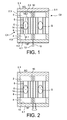
- a recovery and conversion device comprising a first cavity 2, a second cavity 4, a channel 6, said primary channel connecting the first cavity 2 and the second cavity 4, and second channels 8, said secondary channels, connecting the first cavity 2 and the second cavity 4.
- the primary channel extends along a longitudinal axis X.
- the assembly thus formed will be designated cells.
- the device represented on the figure 1 has two cells C1 and C2.
- the cavity 2 comprises a first and a second end wall 2.1, 2.2 and side walls 2.3.
- the first end wall 2.1 is intended to be in contact with a hot source SC; the wall 2.1 will be designated "hot wall” in the following description.
- the temperature reached by the hot wall 2.1 is such that it ensures the vaporization of the fluid contained in the device. It is therefore at least equal to the boiling temperature of the fluid. Examples of fluid will be given below.
- the hot source SC may for example be a face of an electronic component or any other source of heat.
- the cavity 2 will be designated in the following description "chamber” or "vaporization chamber”.
- the end wall 2.2 is traversed by the primary channel 6.
- the walls of the cavity 2 are made of a good thermal conductor material so as to ensure a homogeneous distribution of the temperature throughout the vaporization cavity 2.
- the second cavity 4 comprises a first and a second end wall 4.1, 4.2 and side walls 4.3.
- the end wall 4.1 comprises at least one wall 4.1 intended to be in contact with a cold source SF; wall 4.1 will be designated "cold wall” in the following description.
- the temperature of the cold wall 4.1 is such that it ensures the condensation of the vapor formed in the vaporization chamber 2. It is therefore lower than the boiling temperature of the fluid.
- the cold source SF is for example a finned radiator or directly the ambient air.
- the cavity 4 will be designated in the following description "chamber” or "condensation chamber”.
- the second end wall 4.2 is traversed by the primary channel 6.
- the walls of the second cavity are also made of a good thermal conductor material so as to ensure a homogeneous distribution of the temperature throughout the condensation cavity 4.
- the outer part 9 of the device disposed between the vaporization chamber 2 and the condensation chamber 4 and surrounding the primary channel 6 and the secondary channels 8, is formed of a thermal insulating material such as glass to prevent the heat conduction from the hot wall 2.1 to the cold wall 4.1.
- the device also comprises at least one element capable of transforming a mechanical stress into electrical energy.
- at least one element capable of transforming a mechanical stress into electrical energy.
- it is a piezoelectric material membrane 10 disposed in the cavity 2 against the hot wall 2.1.
- the membrane 10 is suspended by its lateral ends. Only part of it is then in contact with the hot wall 2.1 so as to promote its macroscopic deformation and thus increase the amount of electrical energy generated.
- the piezoelectric membrane 10 is connected to a system for collecting electrical energy, either directly a system 13 consuming the energy produced, or a storage system, such as a battery.
- the connections 12 and the system 13 are shown schematically.
- the connections can be made by brazing with a metal whose melting temperature is lower than that of melting of the piezoelectric material.
- the connection wires exit outside the device via channels made through the outer part of insulating material 9, side walls 4.3 and the cold wall 4.1.
- the connections are made before the assembly of the hot walls 2.1 and cold 4.1 with the outer part of insulating material 9.
- the primary channel 6 has an inner surface 14 such that it displaces G drops of liquid from the cavity 4 to the cavity 2.
- the inner surface 14 has sections 14.1, 14.2, 14.3 having different wettability properties, the sections being distributed along the X axis, so as to form a surface energy gradient surface.
- the sections are more and more wetting toward the first cavity 2.
- a surface has properties of low wettability vis-à-vis a liquid, when the contact angle ⁇ of a drop of said liquid is greater than 90 °.
- hydrophobic surface for a low wetting surface
- hydrophilic surface for a wetting surface
- the wetting properties can be obtained by depositing materials having different wetting affinities with the fluid.
- materials having different wetting affinities can for example, depositing SiOx which has low wettability with respect to water; the contact angle is between 20 ° and 40 ° or graphite fluorides (CFx) which have a hydrophobic character.
- CFx graphite fluorides
- the passage section of the primary channel 6 is greater than that of the secondary channels 8, and is such that it allows the circulation of drops of liquid while the secondary channels 8 are intended to allow only the passage of steam.
- the diameter of the primary channel is of the order of the capillary length, that is to say between 3 mm and 5 mm, advantageously of the order of 4 mm; preferably, the diameter of the secondary channel is of the order of the capillary length divided by 10, that is to say the diameter of the secondary channels is for example less than 0.4 mm.
- the device comprises several secondary channels 8. For example, they are distributed all around the primary channel. It can be envisaged that there is only one secondary channel which has an annular shape and completely surrounds the primary channel.
- the operation of the recovery and conversion device of the figure 1 is as follows: a drop of fluid evaporates suddenly in the vaporization chamber 2 by coming into contact with the hot wall 2.1 which is at a temperature above the boiling temperature of the fluid.
- the sudden evaporation generates a peak pressure in the chambers 2 and 4 and in the primary channels 6 and secondary 8 under the effect of the confinement of the gas.
- This pressure variation triggers a deformation of the piezoelectric membrane 10, which generates a voltage / an electric current at its terminals which is transported by the connections 12 to the consumer or storage system 13.
- the fluid in the gas state is almost instantaneously distributed in the volume of the chambers 2,4 and channels 6, 8 and condenses into a drop of fluid in the chamber 4 in contact with the cold wall 4.1.
- the condensed drop is then subjected to two forces: it is on the one hand attracted in the primary channel 6 of the chamber 4 to the chamber 2 by the internal surface gradient surface energy, this energy gradient created by the physicochemical characteristics of the internal wall 14 of the primary channel 6 allows the drop to minimize its energy by moving along the primary channel 6.
- the secondary channels 8 also have the function of not allowing underpressure to be generated in the chamber 4 due to the displacement of the drop. They therefore allow the pressure to accompany the drop during its transfer from the chamber 4 to the chamber 2. On arriving in the latter the drop is again vaporized suddenly and the cycle starts again.
- the size of the cell and the volume of fluid are for example such that a single drop circulates in the channel and then vaporizes and condenses.
- the operation of the device therefore leads to pressure peaks which are cyclic, from a hot source SC whose temperature does not vary or little or whose temperature varies slowly. These pressure peaks are converted into electricity by the piezoelectric membrane 10.
- the electrical signals are available on the connections of the membrane 10 and are cyclic in time. They can therefore be exploited by electronic circuits for energy recovery and be processed for storage and / or use.
- the device comprises two separate cells C1 and C2, a device with a single cell does not depart from the scope of the present invention.
- a large number of juxtaposed cells are provided so as to maximize the amount of electrical energy recovered.
- the cells may be evenly distributed or not by realizing, for example differences in density to adjust locally and controllably the thermal flux density passing through this structure.
- a piezoelectric membrane could be provided in the condensation chamber 4 only.
- piezoelectric membranes at the side walls and / or in the secondary channels.
- Each C101, C102 cells are similar to cells C1 and C2 of Figures 1 and 2 .
- the device however comprises a channel 116 connecting the chamber 102 of the cell C101 to the condensation chamber 104 'of the cell C102 and a channel 116' connecting the vaporization chamber 102 'of the cell C102 to the condensation chamber 104 of the cell C101.
- the channels 116 and 116 ' are intended to transfer the pressure generated in the vaporization chambers 102, 102' to the condensation chamber 104 ', 104 of the other cell.
- Secondary channels 108 connect the chamber 102 and the chamber 104.
- this coupling advantageously causes the cells to be driven together.
- the surface energy gradient surfaces may be replaced by electro-electrically biasing surfaces.
- an array of electrodes is provided in the wall of the primary channels and are activated gradually to move the drop.
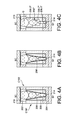
- the primary channel 206 has a variable passage section along the X axis. More particularly, it comprises a section of increasing passage along the axis X of the condensation chamber 204 towards the vaporization chamber 202.
- a piezoelectric membrane 210, 214 is disposed in each chamber 202, 204. In addition, it has a low wetting surface, or hydrophobic in the case of water.
- Secondary channels 208 are also provided.
- the wall of the primary channel 206 has a truncated cone shape.
- the radius of the primary channel 206 increases non-linearly along the X axis so that the inner surface of the primary channel has a convex profile.
- the primary channel 206 is composed of tubular portions 206.1", 206.2 “, 206.3" of increasing section, three in the example shown.
- a drop of liquid progressing in the primary channels is represented on each of the three Figures 4A to 4C .
- Sections 206.1, 206.2, 206.3 would no longer be of constant radius but would be cone-shaped or have a convex interior surface. Any other form facilitating the directional displacement of the drops of liquid is possible.
- the primary channel of Figures 4A to 4C may have a surface with a gradient of surface energy and / or electric polarization effect.
- the exemplary embodiment of the figure 3 in which two cells C101, C102 are coupled can be implemented with the devices of Figures 4A to 4C .
- the device may comprise cells of different types.
- the cells could have different means for moving the drop according to the cells and the arrangement.
- the dimensions of the primary channel and the vaporization and boiling chambers are chosen according to the size of the drops.
- the diameter of the primary channel is preferably equal to or less than that of the drop for surface effects to occur.
- the vaporization and boiling chambers preferably have a volume of between 1 and 10 times the volume of drop to maximize the confining effect and the amplitude of the pressure peaks.
- the channels can be straight or have more complex geometries.
- the channel section may be circular, elliptical, parallelepiped or any other.
- the device comprises a hot wall 2.1 at a temperature of between 110 ° C. and 150 ° C., a cold surface 4.1 at a temperature of between 50 ° C. and 80 ° C., a glass tube 9 connecting the hot wall 2.1 and the wall cold 4.1.
- the primary channel 6 is formed by a stainless steel tube.
- An annular secondary channel 8 is delimited between the stainless steel tube 7 and the glass tube 9, which has a thickness of 0.5 mm.
- the diameter of the primary channel 6 is for example between 1 mm and 4 mm.
- the condensation chamber 4 has a height of the order of 0.5 mm and a diameter of about 10 mm and a vaporization chamber 2 has a diameter of 15 mm and a height of between 1 mm and 3 mm. .
- the heat sources that can be used and that offer temperatures in the range of 110.degree. C. to 150.degree. C. are, for example, plant ducts that are equipped with autonomous sensors powered by the device according to the invention, or underground pipes difficult to reach equipped with autonomous sensors powered by the device according to the invention.
- the device comprises a single cell C1.
- the device comprises a plurality of cells C1, C2, C3 ... distributed in matrix.
- cells are distributed in an eight-pointed star pattern.
- FIG 5D it is the same distribution as that of the Figure 5C but with two types of cells C1, C2, C3 ... and C1 ', C2', C3 '... having different properties so as to adjust their performances or their functional domains and for example to be able to respond to domains different temperatures using fluids of different boiling temperatures, for example, water and ethanol.
- the cells may also have different dimensions.
- the various elements can be made by machining or any other suitable technique.
- microelectronic techniques such as insulating film deposits, conductive wires, lithographies, reactive ion etching (RIE for "reactive ion etching" in English terminology) can be used. Saxon) etc.
- RIE reactive ion etching
- the materials used may be other than those used in microelectronics, such as insulating ceramics, polymers, etc.
- the piezoelectric membranes may be in the form of macroscopic membranes or deposited in the form of thin layers.
- the surface energy gradient surface may for example be obtained by chemical vapor deposition (CVD) of materials with low wettability or good wettability.
- the resin is then removed.
- the first part deposited may be tower protected by a resin, so as to deposit on the second portion of the channel the complementary material with good wettability or low wettability.
- the piezoelectric material membrane (s) may or may be PZT, PLZT, PMNT, PMNZ or PFW.
- the fluid used may be water, solvents, fluids used in thermal applications, fluids charged with particles or mixtures of these fluids.
- solvents mention may be made of hydrofluoroethers.
- the device according to the invention makes it possible, through the use of phase change, to recover and convert thermal energy into electricity by means making it possible to generate periodic peaks of pressure and of voltage / electric current suitable for being used effectively. by electronic circuits for energy recovery.
- the device according to the invention makes it possible, by means of cell density adaptations, i.e. numbers of cells per unit area, to control the heat flow densities transferred by these architectures.
- the device according to the invention adapted to the recovery of thermal energy and its conversion into electrical energy can be used for the supply of low-power electronic devices, for example autonomous sensors.
- this device has the effect of removing heat, it then simultaneously plays the role of electricity cooling system.
- the device according to the invention can also be used as a thermal management device by adapting the quantity of liquid in each cell and the number of cells and their positioning as a function of the temperatures of the zones that it is desired to manage thermally.
- This management can be entirely passive or at least partially active in the case where electrowetting is implemented.
Landscapes
- Physical Or Chemical Processes And Apparatus (AREA)
Description
La présente invention se rapporte à un dispositif de récupération et de conversion d'énergie thermique en énergie électrique en utilisant le changement de phase d'un fluide.The present invention relates to a device for recovering and converting thermal energy into electrical energy by using the phase change of a fluid.
Les circuits électroniques, lors de leur fonctionnement, produisent de la chaleur. Cette chaleur n'est pas utilisée et doit être évacuée afin de ne pas détériorer les circuits. D'autres sources de chaleur sont également présentes dans notre environnement, comme par exemple les canalisations, les échappements, les parois de machines industrielles,..., dont la chaleur dégagée est inutilisée.Electronic circuits, when operating, produce heat. This heat is not used and must be evacuated so as not to damage the circuits. Other sources of heat are also present in our environment, such as pipes, exhausts, walls of industrial machinery, ..., whose heat is unused.
Il est envisagé de récupérer cette chaleur pour la convertir en énergie électrique.It is envisaged to recover this heat to convert it into electrical energy.
Des dispositifs mettant en oeuvre un changement de phase liquide-vapeur ont été proposés.Devices implementing a liquid-vapor phase change have been proposed.
Par exemple, le document
- le liquide s'écoule par gravité à travers les ouvertures en direction de la deuxième paroi. Lorsqu'il entre en contact avec la deuxième paroi, il se vaporise brutalement, ce qui a pour effet de générer une forte surpression et de fortes contraintes mécaniques qui sont transmises à la couche piézoélectrique qui les transforme en signal électrique,
- la vapeur passe à travers les ouvertures dans la couche piézoélectrique en direction de la première paroi, où elle se condense, et
- le liquide s'écoule à nouveau vers la deuxième paroi par gravité et le cycle recommence.
- the liquid flows by gravity through the openings towards the second wall. When it comes into contact with the second wall, it vaporizes suddenly, which has the effect of generating a high pressure and high mechanical stresses which are transmitted to the piezoelectric layer which transforms them into an electrical signal,
- the steam passes through the openings in the piezoelectric layer towards the first wall, where it condenses, and
- the liquid flows back to the second wall by gravity and the cycle starts again.
Ce dispositif présente comme inconvénient de nécessiter d'orienter la deuxième paroi en dessous de la première paroi suivant les forces de gravité pour assurer la chute des gouttes condensées.This device has the disadvantage of requiring to orient the second wall below the first wall according to the forces of gravity to ensure the fall of the condensed drops.
Il est fait également référence au document
C'est par conséquent un but de la présente invention d'offrir un dispositif de récupération et de conversion d'énergie thermique en énergie électrique utilisant le changement de phase d'un fluide, ne nécessitant notamment aucune orientation particulière et permettant une grande miniaturisation.It is therefore an object of the present invention to provide a device for recovering and converting thermal energy into electrical energy using the phase change of a fluid, requiring in particular no particular orientation and allowing great miniaturization.
Le but énoncé ci-dessus est atteint par un dispositif de récupération et de conversion d'énergie thermique en énergie électrique comportant une première cavité dont une paroi est destinée à être en contact avec une source chaude, un deuxième cavité dont une paroi est destinée à être en contact avec une source froide, un matériau piézoélectrique disposé dans au moins une des cavités, un canal primaire connectant la première et la deuxième cavité et au moins un canal secondaire connectant la première et la deuxième cavité, la configuration du canal primaire étant telle qu'elle assure une circulation de gouttes de liquides de la deuxième cavité vers la premières cavité.The aim stated above is achieved by a device for recovering and converting thermal energy into electrical energy comprising a first cavity whose wall is intended to be in contact with a hot source, a second cavity whose wall is intended to in contact with a cold source, a piezoelectric material disposed in at least one of the cavities, a primary channel connecting the first and second cavities and at least one secondary channel connecting the first and second cavities, the configuration of the primary channel being such it ensures a circulation of drops of liquids from the second cavity to the first cavity.
Dans un premier exemple, le canal primaire peut comporter une surface intérieure présentant un gradient d'énergie de surface orienté de sorte à provoquer le déplacement des gouttes de liquide de la deuxième cavité vers la première cavité. Par exemple, dans le cas où le fluide est de l'eau, la surface comporte des sections d'hydrophobies différentes, les sections étant de moins en moins hydrophobes en direction de la première cavité.In a first example, the primary channel may comprise an inner surface having a surface energy gradient oriented so as to cause the displacement of the drops of liquid from the second cavity to the first cavity. For example, in the case where the fluid is water, the surface comprises sections of different hydrophobies, the sections being less and less hydrophobic in the direction of the first cavity.
Dans un autre exemple, le canal principal comporte une section de passage croissante en direction de la première cavité et une surface présentant au moins une propriété d'hydrophobie. Avantageusement, la surface peut présenter une hydrophobie décroissante en direction de la première cavité.In another example, the main channel has an increasing passage section towards the first cavity and a surface having at least one a property of hydrophobicity. Advantageously, the surface may have a decreasing hydrophobicity in the direction of the first cavity.
En d'autres termes, le dispositif comporte une chambre de condensation et une chambre de vaporisation connectées par un canal assurant le transfert des gouttes de liquide de la chambre de condensation vers la chambre de vaporisation sans utiliser les forces de gravité. Au moins l'une des chambres comporte une membrane en matériau piézoélectrique.In other words, the device comprises a condensation chamber and a vaporization chamber connected by a channel ensuring the transfer of drops of liquid from the condensation chamber to the vaporization chamber without using the gravity forces. At least one of the chambers comprises a membrane of piezoelectric material.
La présente invention a alors pour objet un dispositif de récupération et de conversion d'énergie thermique en énergie électrique comportant au moins une cellule comprenant :
- une première cavité dont au moins une partie d'au moins une paroi est destinée à être en contact avec une source de chaleur,
- une deuxième cavité dont au moins une partie d'au moins une paroi est destinée à être en contact avec une source froide,
- un canal primaire reliant la première cavité et la deuxième cavité destiné à transporter un fluide sous forme de gouttes liquides, le canal primaire comportant des moyens de déplacement assurant le transport de gouttes de fluide liquide de la deuxième cavité vers la première cavité,
- au moins un canal secondaire reliant la première cavité et la deuxième cavité destiné à transporter le fluide sous forme de gaz,
- au moins un matériau piézoélectrique disposé dans au moins l'une des première et deuxième cavités,
- un fluide sous forme liquide et gazeuse confiné dans la cellule,
- des moyens de connexion dudit matériau piézoélectrique à un dispositif de récupération de l'énergie électrique générée par le matériau piézoélectrique.
- a first cavity of which at least a part of at least one wall is intended to be in contact with a source of heat,
- a second cavity of which at least a part of at least one wall is intended to be in contact with a cold source,
- a primary channel connecting the first cavity and the second cavity intended to transport a fluid in the form of liquid drops, the primary channel comprising displacement means ensuring the transport of drops of liquid fluid from the second cavity to the first cavity,
- at least one secondary channel connecting the first cavity and the second cavity intended to transport the fluid in the form of a gas,
- at least one piezoelectric material disposed in at least one of the first and second cavities,
- a fluid in liquid and gaseous form confined in the cell,
- means for connecting said piezoelectric material to a device for recovering the electrical energy generated by the piezoelectric material.
De manière avantageuse, les moyens de déplacement sont formés par la surface interne du canal primaire présentant un gradient d'énergie de surface orientée de telle sorte que les gouttes de liquide se déplacent de la deuxième cavité vers la première cavité.Advantageously, the displacement means are formed by the inner surface of the primary channel having a surface energy gradient oriented so that the drops of liquid move from the second cavity to the first cavity.
Dans un exemple de réalisation, le gradient d'énergie de surface est obtenue par au moins une première et une deuxième section de surface disposées successivement dans cet ordre entre la deuxième cavité et la première cavité, chacune desdites sections présentant des propriétés de mouillabilité vis-à-vis du fluide, la mouillabilité de la deuxième section étant supérieure à celle de la première section. Les propriétés de mouillabilité peuvent être obtenues part une couche d'un matériau présentant lesdites propriétés de mouillabilité et/ou par structuration d'au moins une section de la surface interne.In an exemplary embodiment, the surface energy gradient is obtained by at least a first and a second surface section successively arranged in this order between the second cavity and the first cavity, each of said sections having wettability properties vis-à-vis the fluid, the wettability of the second section being greater than that of the first section. The wettability properties can be obtained from a layer of a material having said wettability properties and / or by structuring at least one section of the inner surface.
Par exemple, le canal primaire présente une section de passage croissante de la deuxième cavité vers la première cavité.For example, the primary channel has a section of increasing passage from the second cavity to the first cavity.
Au moins une partie de la surface interne du canal primaire du côté de la deuxième cavité peut présenter des propriétés de faible mouillabilité vis-à-vis du fluide.At least a portion of the inner surface of the primary channel on the side of the second cavity may have properties of low wettability vis-à-vis the fluid.
Dans un autre exemple de réalisation, les moyens de déplacement sont de type électrostatique, par exemple mettent en oeuvre le phénomène d'électromouillage.In another embodiment, the displacement means are of the electrostatic type, for example implement the phenomenon of electrowetting.
Le canal primaire peut présenter une forme évasée ou comporter au moins deux tronçons successifs présentant des sections de passage différentes, les sections de passage augmentant de la deuxième cavité vers la première cavité.The primary channel may have a flared shape or comprise at least two successive sections having different passage sections, the passage sections increasing from the second cavity to the first cavity.
La section de passage du canal secondaire peut être telle qu'elle empêche le passage de gouttes liquides. La section du canal secondaire est de préférence inférieure à 0,1 fois la longueur capillaire.The passage section of the secondary channel may be such that it prevents the passage of liquid drops. The section of the secondary channel is preferably less than 0.1 times the capillary length.
Selon une caractéristique additionnelle, le canal secondaire débouche dans la deuxième cavité à proximité d'une extrémité du canal primaire débouchant dans ladite deuxième cavité.According to an additional feature, the secondary channel opens into the second cavity near an end of the primary channel opening into said second cavity.
Le dispositif de récupération et de conversion d'énergie thermique en énergie électrique peut avantageusement comporter au moins une première et une deuxième cellules, et un canal de transfert connectant la première cavité de la première cellule à la deuxième cavité de la deuxième cellule et la deuxième cavité de la première cellule à la première cavité de la deuxième cellule.The device for recovering and converting thermal energy into electrical energy may advantageously comprise at least a first and a second cell, and a transfer channel connecting the first cavity of the first cell to the second cavity of the second cell and the second cavity of the first cell to the first cavity of the second cell.
De préférence, les parois des première et deuxième cavités sont réalisées en un matériau bon conducteur thermique et dans lequel le dispositif comporte un élément extérieur reliant les parois des première et deuxième cavités, ledit élément extérieur étant en matériau isolant thermique.Preferably, the walls of the first and second cavities are made of a good thermal conductor material and wherein the device comprises an outer element connecting the walls of the first and second cavities, said outer member being of thermal insulating material.
Le dispositif comporte avantageusement un matériau piézoélectrique dans les première et deuxième cavités. Le ou les matériaux piézoélectriques peut ou peuvent être en contact avec la paroi destinée à être en contact de la source chaude et/ou de la source froide. Le ou les matériaux piézoélectriques est ou sont de préférence sous forme de membranes suspendues.The device advantageously comprises a piezoelectric material in the first and second cavities. The piezoelectric material (s) may or may be in contact with the wall intended to be in contact with the hot source and / or the cold source. The piezoelectric material (s) is (are) preferably in the form of suspended membranes.
Le diamètre du canal primaire est par exemple égal ou inférieur à celui des gouttes de liquide.For example, the diameter of the primary channel is equal to or less than that of the drops of liquid.
Le volume de la première et/ou de la deuxième cavité peut être compris entre 1 et 10 fois le volume d'une goutte de liquide.The volume of the first and / or second cavity may be between 1 and 10 times the volume of a drop of liquid.
Par exemple, le fluide mis en oeuvre peut être l'eau ou un solvant, par exemple un hydrofluoroéther.For example, the fluid used may be water or a solvent, for example a hydrofluoroether.
Le dispositif de récupération et de conversion d'énergie thermique en énergie électrique peut comporter une pluralité de cellules adjacentes réparties avec une densité variable en fonction de la densité locale du flux thermique émis par la source chaude.The device for recovering and converting thermal energy into electrical energy may comprise a plurality of adjacent cells distributed with a variable density depending on the local density of the thermal flux emitted by the hot source.
La présente invention a également pour objet un système de récupération et de conversion d'énergie thermique en énergie électrique comportant un dispositif de récupération et de conversion d'énergie thermique en énergie électrique selon l'invention, dans lequel la température de la source chaude est telle que la paroi de la première cavité en contact avec celle-ci est au moins égale à la température d'ébullition dudit fluide. Par exemple, la source chaude est formée par dispositif électronique portable.The present invention also relates to a system for recovering and converting thermal energy into electrical energy comprising a device for recovering and converting thermal energy into electrical energy according to the invention, in which the temperature of the hot source is such that the wall of the first cavity in contact therewith is at least equal to the boiling temperature of said fluid. For example, the hot source is formed by portable electronic device.
La présente invention sera mieux comprise à l'aide de la description qui va suivre et des dessins en annexes sur lesquels :
- la
figure 1 est une vue en coupe longitudinale schématique d'un exemple de réalisation d'un dispositif de récupération et de conversion selon un premier mode de réalisation, - la
figure 2 est une vue en coupe longitudinale schématique d'une variante du dispositif de lafigure 1 , - la
figure 3 est une vue en coupe longitudinale schématique d'un autre exemple de réalisation d'un dispositif selon la premier mode de réalisation, - les
figures 4A à 4C son des vues en coupe longitudinales schématiques de différents exemples de réalisation d'un dispositif de récupération et de conversion selon un deuxième mode de réalisation, - les
figures 5A à 5D sont des vues de dessus d'exemples de répartition de dispositifs de récupération selon l'invention, - la
figure 6 est une vue en coupe longitudinale d'un exemple de réalisation pratique d'un dispositif de récupération et de conversion selon l'invention,
- the
figure 1 is a schematic longitudinal sectional view of an exemplary embodiment of a recovery and conversion device according to a first embodiment, - the
figure 2 is a schematic longitudinal sectional view of a variant of the device of thefigure 1 , - the
figure 3 is a schematic longitudinal sectional view of another embodiment of a device according to the first embodiment, - the
Figures 4A to 4C its schematic longitudinal sectional views of different embodiments of a recovery and conversion device according to a second embodiment, - the
Figures 5A to 5D are top views of examples of distribution of recovery devices according to the invention, - the
figure 6 is a longitudinal sectional view of an exemplary practical embodiment of a recovery and conversion device according to the invention,
Sur la
La cavité 2 comporte une première et une deuxième paroi d'extrémité 2.1, 2.2 et des parois latérales 2.3. Dans l'exemple représenté, la première paroi d'extrémité 2.1 est destinée à être en contact avec une source chaude SC ; la paroi 2.1 sera désignée « paroi chaude » dans la suite de la description. La température atteinte par la paroi chaude 2.1 est telle qu'elle assure la vaporisation du fluide contenu dans le dispositif. Elle est donc au moins égale à la température d'ébullition du fluide. Des exemples de fluide seront donnés ci-dessous.The
La source chaude SC peut par exemple être une face d'un composant électronique ou de toute autre source de chaleur.The hot source SC may for example be a face of an electronic component or any other source of heat.
La cavité 2 sera désignée dans la suite de la description « chambre » ou « chambre de vaporisation ».The
La paroi d'extrémité 2.2 est traversée par le canal primaire 6.The end wall 2.2 is traversed by the
De manière préférentielle, les parois de la cavité 2 sont en matériau bon conducteur thermique de sorte à assurer une répartition homogène de la température dans toute la cavité de vaporisation 2.Preferably, the walls of the
La deuxième cavité 4 comporte une première et une deuxième paroi d'extrémité 4.1, 4.2 et des parois latérales 4.3. Dans l'exemple, la paroi d'extrémité 4.1 comporte au moins une paroi 4.1 destinée à être en contact avec une source froide SF; la paroi 4.1 sera désignée « paroi froide » dans la suite de la description. La température de la paroi froide 4.1 est telle qu'elle assure la condensation de la vapeur formée dans la chambre de vaporisation 2. Elle est donc inférieure à la température d'ébullition du fluide.The
La source froide SF est par exemple un radiateur à ailette ou directement l'air ambiant.The cold source SF is for example a finned radiator or directly the ambient air.
La cavité 4 sera désignée dans la suite de la description « chambre » ou « chambre de condensation ».The
La deuxième paroi d'extrémité 4.2 est traversée par le canal primaire 6.The second end wall 4.2 is traversed by the
De manière préférentielle, les parois de la deuxième cavité sont également en matériau bon conducteur thermique de sorte à assurer une répartition homogène de la température dans toute la cavité de condensation 4.Preferably, the walls of the second cavity are also made of a good thermal conductor material so as to ensure a homogeneous distribution of the temperature throughout the
En outre, la partie extérieure 9 du dispositif, disposée entre la chambre de vaporisation 2 et la chambre de condensation 4 et entourant le canal primaire 6 et les canaux secondaires 8, est formée en un matériau isolant thermique comme par exemple le verre pour éviter la conduction de la chaleur de la paroi chaude 2.1 vers la paroi froide 4.1.In addition, the
Le dispositif comporte également au moins un élément apte à transformer une contrainte mécanique en énergie électrique. Dans l'exemple représenté, il s'agit d'une membrane en matériau piézoélectrique 10 disposée dans la cavité 2 contre la paroi chaude 2.1.The device also comprises at least one element capable of transforming a mechanical stress into electrical energy. In the example shown, it is a
De manière avantageuse, la membrane 10 est suspendue par ses extrémités latérales. Une partie seulement de celle-ci est alors en contact avec la paroi chaude 2.1 de sorte à favoriser sa déformation macroscopique et donc augmenter la quantité d'énergie électrique générée.Advantageously, the
La membrane piézoélectrique 10 est connectée à un système de collecte de l'énergie électrique, soit directement un système 13 consommant l'énergie produite, soit un système de stockage, tel qu'une batterie. Les connexions 12 et le système 13 sont représentés de manière schématique. Les connexions peuvent être réalisées par brasure avec un métal dont la température de fusion est inférieure à celle de fusion du matériau piézoélectrique. Les fils de connexion sortent à l'extérieur du dispositif via des canaux réalisés au travers de la partie extérieure en matériau isolant 9, des parois latérales 4.3 et de la paroi froide 4.1. Les connexions sont réalisées avant l'assemblage des parois chaude 2.1 et froide 4.1 avec la partie extérieure en matériau isolant 9.The
En outre, le canal primaire 6 comporte une surface intérieure 14 telle qu'elle assure le déplacement de gouttes G de liquide de la cavité 4 vers la cavité 2. Dans l'exemple représenté, la surface intérieure 14 comporte des sections 14.1, 14.2, 14.3 présentant des propriétés de mouillabilité différentes, les sections étant réparties le long de l'axe X, de sorte à former une surface à gradient d'énergie de surface.In addition, the
Les sections sont de plus en plus mouillantes en direction de la première cavité 2.The sections are more and more wetting toward the
Une surface présente des propriétés de faible mouillabilité vis-à-vis d'un liquide, lorsque l'angle de contact θ d'une goutte dudit liquide est supérieur à 90°.A surface has properties of low wettability vis-à-vis a liquid, when the contact angle θ of a drop of said liquid is greater than 90 °.
Dans le cas de l'eau, on parle de surface hydrophobe pour une surface faiblement mouillante, et de surface hydrophile pour une surface mouillante. Dans la suite de la description nous considérerons le cas de l'eau à des fins de simplicité, l'invention n'étant pas limitée à l'eau.In the case of water, it is called hydrophobic surface for a low wetting surface, and hydrophilic surface for a wetting surface. In the following description we will consider the case of water for the sake of simplicity, the invention is not limited to water.
Les propriétés de mouillage peuvent être obtenues par le dépôt de matériaux présentant des affinités de mouillage différentes avec le fluide. On peut par exemple déposer du SiOx qui présente une faible mouillabilité par rapport à l'eau; l'angle de contact est compris entre 20° et 40° ou des fluorures de graphite (CFx) qui ont un caractère hydrophobe. On peut également modifier le niveau de mouillabilité par structuration, avantageusement par nanostructuration de la surface interne du canal primaire 6. En réalisant deux nanostructurations différentes, on peut réaliser deux sections ayant des mouillabilités différentes. La nanostructuration peut prendre la forme de cuvettes de taille nanométrique à micrométrique ménagées en surface du matériau.The wetting properties can be obtained by depositing materials having different wetting affinities with the fluid. We can for example, depositing SiOx which has low wettability with respect to water; the contact angle is between 20 ° and 40 ° or graphite fluorides (CFx) which have a hydrophobic character. It is also possible to modify the level of wettability by structuring, advantageously by nanostructuring the internal surface of the
La section de passage du canal primaire 6 est supérieure à celui des canaux secondaires 8, et est telle qu'elle permet la circulation de gouttes de liquide tandis que les canaux secondaires 8 sont destinés à ne permettre que le passage de la vapeur.The passage section of the
Dans le cas de l'eau, de préférence le diamètre du canal primaire est de l'ordre de la longueur capillaire, c'est-à-dire comprise entre 3 mm et 5 mm, avantageusement de l'ordre de 4 mm; de préférence, le diamètre du canal secondaire est de l'ordre de la longueur capillaire divisée par 10, c'est-à-dire le diamètre des canaux secondaires est par exemple inférieur à 0,4 mm.In the case of water, preferably the diameter of the primary channel is of the order of the capillary length, that is to say between 3 mm and 5 mm, advantageously of the order of 4 mm; preferably, the diameter of the secondary channel is of the order of the capillary length divided by 10, that is to say the diameter of the secondary channels is for example less than 0.4 mm.
Dans l'exemple représenté, le dispositif comporte plusieurs canaux secondaires 8. Par exemple, ils sont répartis tout autour du canal primaire. On peut envisager qu'il n'y ait qu'un canal secondaire qui présente une forme annulaire et entoure complètement le canal primaire.In the example shown, the device comprises several
Le fonctionnement du dispositif de récupération et de conversion de la
D'autre part, elle est aussi poussée dans la même direction par la pression transmise de la chambre 2 qui s'échauffe vers la chambre 4 par les canaux secondaires 8 dont la taille est trop faible pour laisser passer une goutte mais suffisamment grande pour transmettre la pression. Les canaux secondaires 8 ont aussi pour fonction de ne pas laisser une sous-pression se générer dans la chambre 4 du fait du déplacement de la goutte. Ils permettent donc à la pression d'accompagner la goutte lors de son transfert de la chambre 4 vers la chambre 2. En arrivant dans cette dernière la goutte est à nouveau vaporisée brutalement et le cycle recommence.On the other hand, it is also pushed in the same direction by the pressure transmitted from the
La taille de la cellule et le volume de fluide sont par exemple tels qu'une seule goutte circule dans le canal puis se vaporise et se condense.The size of the cell and the volume of fluid are for example such that a single drop circulates in the channel and then vaporizes and condenses.
Le fonctionnement du dispositif conduit donc à des pics de pression qui sont cycliques, à partir d'une source chaude SC dont la température ne varie pas ou peu ou alors dont la température varie lentement. Ces pics de pression sont convertis en électricité par la membrane piézoélectrique 10.The operation of the device therefore leads to pressure peaks which are cyclic, from a hot source SC whose temperature does not vary or little or whose temperature varies slowly. These pressure peaks are converted into electricity by the
Les signaux électriques sont disponibles sur les connexions de la membrane 10 et sont cycliques dans le temps. Ils peuvent donc être exploités par des circuits électroniques de récupération d'énergie et être traités pour être stockés et/ou utilisés.The electrical signals are available on the connections of the
Dans l'exemple de la
Les cellules peuvent êtres réparties uniformément ou non en réalisant par exemple des différences de densité pour ajuster localement et de façon contrôlable la densité de flux thermique passant au travers de cette structure.The cells may be evenly distributed or not by realizing, for example differences in density to adjust locally and controllably the thermal flux density passing through this structure.
Sur la
On pourrait prévoir une membrane piézoélectrique dans la chambre de condensation 4 uniquement.A piezoelectric membrane could be provided in the
Alternativement on pourrait prévoir des membranes piézoélectriques au niveau des parois latérales et/ou dans les canaux secondaires.Alternatively one could provide piezoelectric membranes at the side walls and / or in the secondary channels.
Sur la
Chaque cellules C101, C102 sont similaires aux cellules C1 et C2 des
Des canaux secondaires 108 connectent la chambre 102 et la chambre 104.Secondary channels 108 connect the
Dans cet exemple de réalisation, outre les forces exercées par les surfaces à gradient d'énergie de surface des canaux primaires, c'est la pression du gaz généré par la vaporisation d'une goutte dans la chambre de vaporisation 102 de la cellule C101 qui génère la force de déplacement de la goutte de la chambre de condensation 104' vers la chambre de vaporisation 102' de la cellule C102, et c'est la pression du gaz généré par la vaporisation d'une goutte dans la chambre de vaporisation 102', qui génère la force de déplacement de la goutte de la chambre de condensation 104 vers la chambre de vaporisation 102 de la cellule C101 comme montré sur la
Dans cet exemple de réalisation, ce couplage provoque avantageusement un entraînement des cellules entre elles.In this embodiment, this coupling advantageously causes the cells to be driven together.
De manière alternative, les surfaces à gradient d'énergie de surface peuvent être remplacées par des surfaces présentant des effets de polarisation électrique, de type électromouillage. Pour cela un réseau d'électrodes est prévu dans la paroi des canaux primaires et sont activées progressivement pour déplacer la goutte.Alternatively, the surface energy gradient surfaces may be replaced by electro-electrically biasing surfaces. For this purpose an array of electrodes is provided in the wall of the primary channels and are activated gradually to move the drop.
Sur les
Le canal primaire 206 comporte une section de passage variable le long de l'axe X. Plus particulièrement il comporte une section de passage croissante le long de l'axe X de la chambre de condensation 204 vers la chambre de vaporisation 202. Une membrane piézoélectrique 210, 214 est disposée dans chaque chambre 202, 204. En outre, il présente une surface faiblement mouillante, ou hydrophobe dans le cas de l'eau. Des canaux secondaires 208 sont également prévus.The
Sur la
Sur la
Sur la
Une goutte de liquide progressant dans les canaux primaire est représentée sur chacune des trois
On pourrait prévoir de combiner par exemple les formes des
Dans un autre exemple de réalisation, le canal primaire des
L'exemple de réalisation de la
Comme expliqué ci-dessus avec la
Les dimensions du canal primaire et des chambres de vaporisation et d'ébullition sont choisies en fonction de la taille des gouttes. Le diamètre du canal primaire est de préférence égal ou inférieur à celui de la goutte pour que les effets de surface interviennent. Les chambres de vaporisation et d'ébullition ont de préférence un volume compris entre 1 et 10 fois le volume de goutte pour maximiser l'effet de confinement et l'amplitude des pics de pression.The dimensions of the primary channel and the vaporization and boiling chambers are chosen according to the size of the drops. The diameter of the primary channel is preferably equal to or less than that of the drop for surface effects to occur. The vaporization and boiling chambers preferably have a volume of between 1 and 10 times the volume of drop to maximize the confining effect and the amplitude of the pressure peaks.
Dans l'exemple représenté, les canaux peuvent être droits ou présenter des géométries plus complexes. En outre, la section des canaux peut être circulaire, elliptique, parallélépipédique ou tout autre.In the example shown, the channels can be straight or have more complex geometries. In addition, the channel section may be circular, elliptical, parallelepiped or any other.
Sur la
Le dispositif comporte une paroi chaude 2.1 à une température comprise entre 110°C et 150°C, une surface froide 4.1 à une température comprise entre 50°C et 80°C, un tube en verre 9 reliant la paroi chaude 2.1 et la paroi froide 4.1.The device comprises a hot wall 2.1 at a temperature of between 110 ° C. and 150 ° C., a cold surface 4.1 at a temperature of between 50 ° C. and 80 ° C., a
Le canal primaire 6 est formé par un tube en acier inox. Un canal secondaire annulaire 8 est délimité entre le tube en acier inox 7 et le tube en verre 9, celui-ci présente une épaisseur de 0,5 mm. Le diamètre du canal primaire 6 est par exemple compris entre 1 mm et 4 mm.The
La chambre de condensation 4 a une hauteur de l'ordre de 0,5 mm et un diamètre de l'ordre de 10 mm environ et une chambre de vaporisation 2 a un diamètre de 15 mm et une hauteur comprise entre 1 mm et 3 mm.The
Par exemple, les sources de chaleur utilisables et offrant des températures de l'ordre de 110°C à 150°C sont par exemple les canalisations d'usine que l'on équipe de capteurs autonomes alimentés par le dispositif selon l'invention, ou des canalisations enterrées difficilement atteignables équipées de capteurs autonomes alimentés par le dispositif selon l'invention.For example, the heat sources that can be used and that offer temperatures in the range of 110.degree. C. to 150.degree. C. are, for example, plant ducts that are equipped with autonomous sensors powered by the device according to the invention, or underground pipes difficult to reach equipped with autonomous sensors powered by the device according to the invention.
Sur les
Sur la
Dans le cas de dispositifs de taille macroscopique, les différents éléments peuvent être réalisés par usinage ou toute autre technique adaptée.In the case of devices of macroscopic size, the various elements can be made by machining or any other suitable technique.
Dans le cas de dispositif à l'échelle microscopique, on peut utiliser des techniques de microélectronique, telles que les dépôts de films isolants, de fils conducteurs, lithographies, par gravures ionique réactive (RIE pour "Reactive-ion Etching" en terminologie anglo-saxonne) etc. De plus les matériaux utilisés peuvent être autres que ceux utilisés dans la microélectronique, comme par exemple les céramiques isolantes, les polymères...In the case of a microscopically-scale device, microelectronic techniques, such as insulating film deposits, conductive wires, lithographies, reactive ion etching (RIE for "reactive ion etching" in English terminology) can be used. Saxon) etc. In addition, the materials used may be other than those used in microelectronics, such as insulating ceramics, polymers, etc.
Les membranes piézoélectriques pourront être sous forme de membranes macroscopiques ou déposées sous forme de couches minces.The piezoelectric membranes may be in the form of macroscopic membranes or deposited in the form of thin layers.
La surface de gradient d'énergie de surface pourra par exemple être obtenue par dépôt chimique en phase vapeur (CVD pour "Chemical Vapor Deposition") de matériaux à faible mouillabilité ou à bonne mouillabilité.The surface energy gradient surface may for example be obtained by chemical vapor deposition (CVD) of materials with low wettability or good wettability.
Par exemple, pour réaliser les différentes sections présentant des propriétés de mouillabilité différentes, on peut par exemple protéger une partie du canal primaire par un matériau sacrificiel comme une résine, de façon à déposer dans un deuxième temps le matériau à faible mouillabilité ou à bonne mouillabilité. La résine est ensuite retirée. Dans une deuxième étape, la première partie déposée pourra être à son tour protégée par une résine, de façon à déposer sur la deuxième partie du canal le matériau complémentaire à bonne mouillabilité ou à faible mouillabilité. Ainsi peuvent être réalisés des canaux présentant un gradient d'énergie de surface le long de leurs axes.For example, to achieve the different sections having different wettability properties, one can for example protect a portion of the primary channel by a sacrificial material such as a resin, so as to deposit in a second time the low wettability material or good wettability . The resin is then removed. In a second step, the first part deposited may be tower protected by a resin, so as to deposit on the second portion of the channel the complementary material with good wettability or low wettability. Thus can be realized channels having a surface energy gradient along their axes.
Dans le cas de gouttes de faible diamètre, par exemple inférieur au millimètre, une surface ainsi réalisée assure un meilleur contrôle du déplacement de la goutte.In the case of drops of small diameter, for example less than a millimeter, a surface thus produced provides better control of the displacement of the drop.
A titre d'exemple, les matériaux mis en oeuvre peuvent être :
- pour les matériaux conducteurs thermiques, il peut s'agir d'un métal comme le cuivre, l'aluminium, etc. Il peut s'agir de matériaux anisotropes tels que le graphite, des nanocomposites comprenant des nanotubes de carbone,
- pour les matériaux isolants thermiques et électriques, on peut choisir un polymère, la silice ou une céramique isolante telle que la zircone ou l'alumine,
- pour réaliser la surface à gradient d'énergie de surface, les matériaux peuvent être le SiOx ou CFx, de surfaces nanostructurées.
- for thermally conductive materials, it may be a metal such as copper, aluminum, etc. It may be anisotropic materials such as graphite, nanocomposites comprising carbon nanotubes,
- for thermal and electrical insulating materials, it is possible to choose a polymer, silica or an insulating ceramic such as zirconia or alumina,
- to achieve the surface energy gradient surface, the materials may be SiOx or CFx, nanostructured surfaces.
Par exemple, la ou les membranes en matériau piézoélectrique peut ou peuvent être en PZT, PLZT, PMNT, PMNZ ou en PFW.For example, the piezoelectric material membrane (s) may or may be PZT, PLZT, PMNT, PMNZ or PFW.
Enfin, le fluide mis en oeuvre peut être de l'eau, des solvants, des fluides utilisés dans les applications thermiques, des fluides chargés de particules ou des mélanges de ces fluides. Parmi les solvants préférés, on peut citer les hydrofluoroéthers.Finally, the fluid used may be water, solvents, fluids used in thermal applications, fluids charged with particles or mixtures of these fluids. Among the preferred solvents, mention may be made of hydrofluoroethers.
Le dispositif selon l'invention permet grâce à l'utilisation de changement de phase, de récupérer et convertir de l'énergie thermique en électricité par un moyen permettant de générer des pics périodiques de pression et de tension/courant électrique propres à être utilisés efficacement par des circuits électroniques de récupération d'énergie.The device according to the invention makes it possible, through the use of phase change, to recover and convert thermal energy into electricity by means making it possible to generate periodic peaks of pressure and of voltage / electric current suitable for being used effectively. by electronic circuits for energy recovery.
Celui-ci permet, grâce à la mise en oeuvre de canaux primaires comportant des surfaces internes à gradient d'énergie de surface, des canaux primaires à géométries adaptées, ou des canaux à polarisation électrique adaptée, ou d'une combinaison de ses moyens, ainsi que des canaux secondaires, de générer une force de transfert des gouttes qui permet de miniaturiser les dispositifs vers des dimensions caractéristiques de canaux de l'ordre de 10 µm à plusieurs millimètres, et d'utiliser des dispositifs dans toutes les positions, y compris lorsque la source chaude se situe en dessous de la source froide ou lorsque l'axe est dans une position horizontale. Cette liberté d'orientation du dispositif est particulièrement intéressante dans le cas d'une source chaude formée par un dispositif solaire qui est situé dans une partie supérieure, ou de dispositifs mobiles ou d'électronique portable dont l'orientation peut varier au cours de l'utilisation.This allows, thanks to the implementation of primary channels having internal surfaces with a gradient of surface energy, primary channels with adapted geometries, or channels with suitable electrical polarization, or a combination of its means, as well as secondary channels, to generate a drop transfer force which makes it possible to miniaturize the devices to characteristic channel dimensions of the order of 10 μm to several millimeters, and to use devices in all positions, including when the hot source is below the cold source or when the axis is in a horizontal position. This freedom of orientation of the device is particularly advantageous in the case of a hot source formed by a solar device which is located in an upper part, or mobile devices or portable electronics whose orientation may vary during the 'use.
De plus, le dispositif selon l'invention permet, grâce à des adaptations de densité de cellules, i.e. nombres de cellules par unité de surface, de contrôler les densités de flux thermiques transférés par ces architectures.In addition, the device according to the invention makes it possible, by means of cell density adaptations, i.e. numbers of cells per unit area, to control the heat flow densities transferred by these architectures.
Le dispositif selon l'invention adapté à la récupération d'énergie thermique et à sa conversion en énergie électrique peut être utilisé pour l'alimentation de dispositifs électroniques basse consommation, par exemple des capteurs autonomes.The device according to the invention adapted to the recovery of thermal energy and its conversion into electrical energy can be used for the supply of low-power electronic devices, for example autonomous sensors.
En outre, en utilisant des fluides ayant une température d'ébullition adaptée, des dispositifs fonctionnant à des températures différentes peuvent être fabriqués.In addition, by using fluids having a suitable boiling temperature, devices operating at different temperatures can be manufactured.
Par conséquent, outre le fait d'utiliser la chaleur pour produire de l'énergie thermique, ce dispositif a pour effet d'évacuer la chaleur, il joue alors simultanément à la génération d'électricité le rôle de système de refroidissement.Therefore, besides the fact of using heat to produce heat energy, this device has the effect of removing heat, it then simultaneously plays the role of electricity cooling system.
Le dispositif selon l'invention peut également être utilisé comme dispositif de gestion thermique en adaptant la quantité de liquide dans chaque cellule et le nombre de cellule et leur positionnement en fonction des températures des zones que l'on souhaite gérer thermiquement. Cette gestion peut être entièrement passive ou être au moins partiellement active dans le cas où l'on met en oeuvre l'électromouillage.The device according to the invention can also be used as a thermal management device by adapting the quantity of liquid in each cell and the number of cells and their positioning as a function of the temperatures of the zones that it is desired to manage thermally. This management can be entirely passive or at least partially active in the case where electrowetting is implemented.
Claims (16)
- A device for recovering and converting heat energy into electrical energy comprising at least one cell (C1, C2, C101, C102) comprising:- a first cavity (2, 2') at least one part of at least one wall (2.1) of which is configured to contact a heat source (HS),- a second cavity (4, 4') at least one part of at least one wall (4.1) of which is configured to contact a cold source (CS),- a primary channel (6) connecting the first cavity (2) and the second cavity (4) intended to transport a fluid as liquid drops, the primary channel comprising means providing transport of liquid fluid drops from the second cavity (4) to the first cavity (2),- at least one secondary channel (8) connecting the first cavity (2) and the second cavity (4) intended to transport the fluid as a gas,- at least one piezoelectric material (10) provided in at least one of the first (2) and second (4) cavities,- a fluid as a liquid and gas contained within the cell,- means (12) for connecting said piezoelectric material (10) to a device for recovering electrical energy generated by the piezoelectric material (10).
- The device for recovering and converting heat energy into electrical energy according to claim 1, wherein the means providing transport of liquid fluid drops are formed by the inner surface of the primary channel having a surface energy gradient oriented such that the liquid drops move from the second cavity (4, 4') to the first cavity (2, 2').
- The device for recovering and converting heat energy into electrical energy according to claim 2, wherein the surface energy gradient is obtained by at least a first and a second surface portions successively arranged in this order between the second cavity and the first cavity, each of said portions having fluid-wettability properties, the wettability of the second portion being higher than that of the first portion, the wettability properties being advantageously obtained by a layer of a material having said wettability properties and/or by structuring at least one portion of the inner surface.
- The device for recovering and converting heat energy into electrical energy according to claim 1, wherein the means providing transport of liquid fluid drops are of the electrostatic type, for example implement the electro-wetting phenomenon.
- The device for recovering and converting heat energy into electrical energy according to one of claims 1 to 4, wherein the primary channel (6) has a flow cross section raising from the second cavity (4, 4') to the first cavity (2, 2'), advantageously at least one part of the inner surface of the primary channel (6) on the side of the second cavity (4, 4') has low fluid-wettability properties.
- The device for recovering and converting heat energy into electrical energy according to claim 5, wherein the primary channel (6) has a flared shape or the primary channel (6) comprises least two successive segments having different flow cross sections, the flow cross sections increasing from the second cavity (4) to the first cavity (2).
- The device for recovering and converting heat energy into electrical energy according to one of claims 1 to 6, wherein the flow cross section of the secondary channel (8) is such that it prevents liquid drops from flowing through.
- The device for recovering and converting heat energy into electrical energy according to one of claims 1 to 7, wherein the secondary channel (8) opens into the second cavity (4) in the proximity of one end of the primary channel (6) opening into said second cavity (2).
- The device for recovering and converting heat energy into electrical energy according to one of claims 1 to 8, comprising at least a first (C101) and a second (C102) cells, and a transfer channel (116) connecting the first cavity (102) of the first cell (C101) to the second cavity (104') of the second cell (C102) and the second cavity (104) of the first cell (C101) to the first cavity (102') of the second cell (C102).
- The device for recovering and converting heat energy into electrical energy according to one of claims 1 to 9, wherein the walls (2.1, 40.1) of the first (2) and second (4) cavities are made of a good heat conducting material and wherein the device comprises an external element (9) connecting the walls of the first (2) and second (4) cavities, said external element (9) being of a heat insulating material.
- The device for recovering and converting heat energy into electrical energy according to one of claims 1 to 10, wherein the piezoelectric material (s) (10, 14) that can be in one of the first (2) and second (4) cavities or in the first (2) and second (4) cavities, is (are) contacting the wall (2.1, 4.1) configured to contact the hot source (HS) and/or cold source (CS).
- The device for recovering and converting heat energy into electrical energy according to one of claims 1 to 11, the piezoelectric material(s) (10, 14) is (are) as suspended membranes.
- The device for recovering and converting heat energy into electrical energy according to one of claims 1 to 12, wherein the diameter of the primary channel (6) is lower than or equal to that of the liquid drops.
- The device for recovering and converting heat energy into electrical energy according to one of claims 1 to 13, wherein the volume of the first (2) and/or second (4) cavity is between 1 and 10 times the volume of a liquid drop.
- The device for recovering and converting heat energy into electrical energy according to one of claims 1 to 14, comprising a plurality of adjacent cells (C1, C2), said cells (C1, C2) being distributed with a variable density as a function of the local density of the heat flux emitted by the hot source.
- A system for recovering and converting heat energy into electrical energy comprising a device for recovering and converting heat energy into electrical energy according to one of claims 1 to 15, wherein the temperature of the heat source (HS) is such that the temperature of the wall (2.1) of the first cavity (2) contacting the same is at least equal to the boiling temperature of said fluid, the hot source (HS) being advantageously formed by a portable electronic device.
Applications Claiming Priority (2)
| Application Number | Priority Date | Filing Date | Title |
|---|---|---|---|
| FR1251368A FR2986908B1 (en) | 2012-02-14 | 2012-02-14 | DEVICE FOR RECOVERING AND CONVERTING THERMAL ENERGY IN ELECTRICAL ENERGY |
| PCT/EP2013/052815 WO2013120869A1 (en) | 2012-02-14 | 2013-02-13 | Device for recovering and converting heat energy into electrical energy |
Publications (2)
| Publication Number | Publication Date |
|---|---|
| EP2815498A1 EP2815498A1 (en) | 2014-12-24 |
| EP2815498B1 true EP2815498B1 (en) | 2016-01-20 |
Family
ID=47748593
Family Applications (1)
| Application Number | Title | Priority Date | Filing Date |
|---|---|---|---|
| EP13705750.1A Not-in-force EP2815498B1 (en) | 2012-02-14 | 2013-02-13 | Device for recovering and converting heat energy into electrical energy |
Country Status (5)
| Country | Link |
|---|---|
| US (1) | US9444371B2 (en) |
| EP (1) | EP2815498B1 (en) |
| CN (1) | CN104145414A (en) |
| FR (1) | FR2986908B1 (en) |
| WO (1) | WO2013120869A1 (en) |
Families Citing this family (12)
| Publication number | Priority date | Publication date | Assignee | Title |
|---|---|---|---|---|
| FR2973944B1 (en) | 2011-04-06 | 2014-01-10 | Commissariat Energie Atomique | TRANSMITTER FOR THERMOPHOTOVOLTAIC SYSTEM AND THERMOPHOTOVOLTAIC SYSTEM COMPRISING AT LEAST ONE SUITABLE TRANSMITTER |
| FR2977983B1 (en) | 2011-07-11 | 2013-08-16 | Commissariat Energie Atomique | SYSTEM FOR CONVERTING THERMAL ENERGY IN ELECTRICAL ENERGY |
| FR3008691B1 (en) | 2013-07-22 | 2016-12-23 | Commissariat Energie Atomique | DEVICE COMPRISING A FLUID CHANNEL PROVIDED WITH AT LEAST ONE MICRO OR NANOELECTRONIC SYSTEM AND METHOD OF MAKING SUCH A DEVICE |
| FR3008690B1 (en) | 2013-07-22 | 2016-12-23 | Commissariat Energie Atomique | DEVICE COMPRISING A FLUID CHANNEL PROVIDED WITH AT LEAST ONE MICRO OR NANOELECTRONIC SYSTEM AND METHOD OF MAKING SUCH A DEVICE |
| FR3009907B1 (en) * | 2013-08-20 | 2015-09-18 | Commissariat Energie Atomique | DEVICE FOR CONVERTING THERMAL ENERGY IN ELECTRICAL ENERGY |
| US9793829B2 (en) * | 2013-09-25 | 2017-10-17 | Prime Photonics, Lc | Magneto-thermoelectric generator for energy harvesting |
| FR3032845B1 (en) | 2015-02-13 | 2017-03-10 | St Microelectronics Crolles 2 Sas | THERMAL ENERGY RECOVERY DEVICE |
| US10303647B2 (en) * | 2015-07-15 | 2019-05-28 | Mellanox Technologies, Ltd. | Access control in peer-to-peer transactions over a peripheral component bus |
| CN105897049B (en) * | 2016-06-06 | 2017-12-19 | 南京航空航天大学 | One kind rotates collision type lunar surface piezoelectric energy collecting device and its method of work |
| EP3331149A1 (en) * | 2016-12-02 | 2018-06-06 | Blunergy SA | Thermoelectric generator |
| EP3431263B1 (en) | 2017-07-21 | 2021-04-21 | CL Schutzrechtsverwaltungs GmbH | Method for operating at least one apparatus for additively manufacturing three-dimensional objects |
| GB2597900B (en) * | 2020-06-11 | 2022-08-24 | Katrick Tech Limited | Heat engine and method of manufacture |
Family Cites Families (14)
| Publication number | Priority date | Publication date | Assignee | Title |
|---|---|---|---|---|
| US6360775B1 (en) | 1998-12-23 | 2002-03-26 | Agilent Technologies, Inc. | Capillary fluid switch with asymmetric bubble chamber |
| US7411337B2 (en) * | 2001-11-16 | 2008-08-12 | Intel Corporation | Electrical energy-generating system and devices and methods related thereto |
| GB0311236D0 (en) * | 2003-05-16 | 2003-06-18 | Acton Elizabeth | Improved method of freezing large volumes |
| US20060173344A1 (en) * | 2005-01-19 | 2006-08-03 | Siemens Medical Solutions Usa, Inc. | Method for using a refrigeration system to remove waste heat from an ultrasound transducer |
| WO2006081674A1 (en) * | 2005-02-03 | 2006-08-10 | University Of Manitoba Research Services & Programs | Micro heat engine and method of manufacturing |
| GB2447600A (en) | 2006-01-25 | 2008-09-17 | Univ California | Energy harvesting by means of thermo-mechanical device utilizing bistable ferromagnets |
| EP1998383B1 (en) | 2006-02-27 | 2016-12-28 | Kyocera Corporation | Method for manufacturing ceramic member, and ceramic member for gas sensor device, fuel cell device, filter device, multi-layer piezoelectric device, injection apparatus, and fuel injection system |
| US8432085B2 (en) | 2007-09-18 | 2013-04-30 | Kyocera Corporation | Multi-layer piezoelectric element having low rigidity metal layers, and ejection apparatus and fuel ejection system that employ the same |
| FR2951874B1 (en) * | 2009-10-26 | 2011-12-09 | St Microelectronics Crolles 2 | THERMOELECTRIC GENERATOR |
| JP5660288B2 (en) | 2010-01-05 | 2015-01-28 | セイコーエプソン株式会社 | Liquid ejecting head, liquid ejecting apparatus, piezoelectric element, and liquid ejecting head manufacturing method |
| FR2973944B1 (en) | 2011-04-06 | 2014-01-10 | Commissariat Energie Atomique | TRANSMITTER FOR THERMOPHOTOVOLTAIC SYSTEM AND THERMOPHOTOVOLTAIC SYSTEM COMPRISING AT LEAST ONE SUITABLE TRANSMITTER |
| FR2977121B1 (en) | 2011-06-22 | 2014-04-25 | Commissariat Energie Atomique | THERMAL MANAGEMENT SYSTEM WITH VARIABLE VOLUME MATERIAL |
| US20140174085A1 (en) * | 2012-12-21 | 2014-06-26 | Elwha LLC. | Heat engine |
| FR3008691B1 (en) | 2013-07-22 | 2016-12-23 | Commissariat Energie Atomique | DEVICE COMPRISING A FLUID CHANNEL PROVIDED WITH AT LEAST ONE MICRO OR NANOELECTRONIC SYSTEM AND METHOD OF MAKING SUCH A DEVICE |
-
2012
- 2012-02-14 FR FR1251368A patent/FR2986908B1/en not_active Expired - Fee Related
-
2013
- 2013-02-13 CN CN201380009315.6A patent/CN104145414A/en active Pending
- 2013-02-13 WO PCT/EP2013/052815 patent/WO2013120869A1/en active Application Filing
- 2013-02-13 EP EP13705750.1A patent/EP2815498B1/en not_active Not-in-force
- 2013-02-13 US US14/378,267 patent/US9444371B2/en active Active
Also Published As
| Publication number | Publication date |
|---|---|
| WO2013120869A1 (en) | 2013-08-22 |
| EP2815498A1 (en) | 2014-12-24 |
| US9444371B2 (en) | 2016-09-13 |
| FR2986908B1 (en) | 2014-03-28 |
| US20150001990A1 (en) | 2015-01-01 |
| FR2986908A1 (en) | 2013-08-16 |
| CN104145414A (en) | 2014-11-12 |
Similar Documents
| Publication | Publication Date | Title |
|---|---|---|
| EP2815498B1 (en) | Device for recovering and converting heat energy into electrical energy | |
| EP3732744B1 (en) | Temperature control device for a battery or an electronical power device | |
| EP1881538B1 (en) | Electronic component for heat transfer by boiling and condensation, and manufacturing method | |
| EP2740153B1 (en) | Cooling device provided with a thermoelectric sensor | |
| EP2711299B1 (en) | Thermomechanical structure suitable for a space environment | |
| EP2803085B1 (en) | Passive thermal management device | |
| EP2430694B1 (en) | Compact fuel cell | |
| EP2564176B1 (en) | Device forming a manometer intended for measuring biphase fluid pressure, associated method of manufacture and fluidic network | |
| EP2904343B1 (en) | Heat exchanger for thermal storage system | |
| FR2977121A1 (en) | THERMAL MANAGEMENT SYSTEM WITH VARIABLE VOLUME MATERIAL | |
| EP2181301A1 (en) | Thermal regulation passive device with fluid micro loop and capillary pumping | |
| FR2984472A1 (en) | PASSIVE THERMAL CONTROL DEVICE | |
| FR2951874A1 (en) | THERMOELECTRIC GENERATOR | |
| EP2478321A1 (en) | Heat exchange device with confined convective boiling and improved efficiency | |
| WO2015025106A2 (en) | Device for converting thermal energy into electrical energy | |
| FR2990061A1 (en) | ENERGY SOURCE AND METHOD FOR POWERING A AUTARTIC SYSTEM OF ELECTRIC CONSUMERS AND METHOD OF USING THE SAME | |
| EP2591513B1 (en) | Device for generating current and/or voltage based on a thermoelectric module placed in a flowing fluid | |
| WO2012160162A1 (en) | Fuel cell with improved thermal management | |
| FR3040471A1 (en) | SOLAR CONCENTRATOR WITH THREE DIMENSIONAL ABSORBER | |
| EP3194874B1 (en) | Heat pipe and method for making a heat pipe | |
| EP4323711A1 (en) | Two-phase heat-transfer device with liquid overflow tank | |
| EP3667309A1 (en) | Thermal flow sensor with heating wire | |
| FR2919759A1 (en) | Electromagnetic wave converting method for e.g. aircraft, involves converting energy from electromagnetic waves into heat, converting energy from heat into electricity using vertical super-grids, and storing electrical charges | |
| FR3077627A1 (en) | DETENDER DEVICE FOR INSTALLATION IN AN AIR CONDITIONING CIRCUIT | |
| WO2019007941A1 (en) | Thermal regulation device for at least one electrical energy storage element |
Legal Events
| Date | Code | Title | Description |
|---|---|---|---|
| PUAI | Public reference made under article 153(3) epc to a published international application that has entered the european phase |
Free format text: ORIGINAL CODE: 0009012 |
|
| 17P | Request for examination filed |
Effective date: 20140910 |
|
| AK | Designated contracting states |
Kind code of ref document: A1 Designated state(s): AL AT BE BG CH CY CZ DE DK EE ES FI FR GB GR HR HU IE IS IT LI LT LU LV MC MK MT NL NO PL PT RO RS SE SI SK SM TR |
|
| AX | Request for extension of the european patent |
Extension state: BA ME |
|
| RIN1 | Information on inventor provided before grant (corrected) |
Inventor name: MONFRAY, STEPHANE Inventor name: SKOTNICKI, THOMAS Inventor name: SOUPREMANIEN, ULRICH Inventor name: OLLIER, EMMANUEL |
|
| DAX | Request for extension of the european patent (deleted) | ||
| GRAP | Despatch of communication of intention to grant a patent |
Free format text: ORIGINAL CODE: EPIDOSNIGR1 |
|
| INTG | Intention to grant announced |
Effective date: 20150717 |
|
| RIN1 | Information on inventor provided before grant (corrected) |
Inventor name: SOUPREMANIEN, ULRICH Inventor name: SKOTNICKI, THOMAS Inventor name: MONFRAY, STEPHANE Inventor name: OLLIER, EMMANUEL |
|
| GRAS | Grant fee paid |
Free format text: ORIGINAL CODE: EPIDOSNIGR3 |
|
| GRAA | (expected) grant |
Free format text: ORIGINAL CODE: 0009210 |
|
| AK | Designated contracting states |
Kind code of ref document: B1 Designated state(s): AL AT BE BG CH CY CZ DE DK EE ES FI FR GB GR HR HU IE IS IT LI LT LU LV MC MK MT NL NO PL PT RO RS SE SI SK SM TR |
|
| REG | Reference to a national code |
Ref country code: GB Ref legal event code: FG4D Free format text: NOT ENGLISH |
|
| REG | Reference to a national code |
Ref country code: CH Ref legal event code: EP |
|
| REG | Reference to a national code |
Ref country code: IE Ref legal event code: FG4D Free format text: LANGUAGE OF EP DOCUMENT: FRENCH |
|
| REG | Reference to a national code |
Ref country code: AT Ref legal event code: REF Ref document number: 772127 Country of ref document: AT Kind code of ref document: T Effective date: 20160215 |
|
| REG | Reference to a national code |
Ref country code: FR Ref legal event code: PLFP Year of fee payment: 4 |
|
| REG | Reference to a national code |
Ref country code: DE Ref legal event code: R096 Ref document number: 602013004742 Country of ref document: DE |
|
| REG | Reference to a national code |
Ref country code: LT Ref legal event code: MG4D Ref country code: NL Ref legal event code: MP Effective date: 20160120 |
|
| PG25 | Lapsed in a contracting state [announced via postgrant information from national office to epo] |
Ref country code: BE Free format text: LAPSE BECAUSE OF NON-PAYMENT OF DUE FEES Effective date: 20160229 |
|
| REG | Reference to a national code |
Ref country code: AT Ref legal event code: MK05 Ref document number: 772127 Country of ref document: AT Kind code of ref document: T Effective date: 20160120 |
|
| PG25 | Lapsed in a contracting state [announced via postgrant information from national office to epo] |
Ref country code: NL Free format text: LAPSE BECAUSE OF FAILURE TO SUBMIT A TRANSLATION OF THE DESCRIPTION OR TO PAY THE FEE WITHIN THE PRESCRIBED TIME-LIMIT Effective date: 20160120 |
|
| PG25 | Lapsed in a contracting state [announced via postgrant information from national office to epo] |
Ref country code: FI Free format text: LAPSE BECAUSE OF FAILURE TO SUBMIT A TRANSLATION OF THE DESCRIPTION OR TO PAY THE FEE WITHIN THE PRESCRIBED TIME-LIMIT Effective date: 20160120 Ref country code: GR Free format text: LAPSE BECAUSE OF FAILURE TO SUBMIT A TRANSLATION OF THE DESCRIPTION OR TO PAY THE FEE WITHIN THE PRESCRIBED TIME-LIMIT Effective date: 20160421 Ref country code: HR Free format text: LAPSE BECAUSE OF FAILURE TO SUBMIT A TRANSLATION OF THE DESCRIPTION OR TO PAY THE FEE WITHIN THE PRESCRIBED TIME-LIMIT Effective date: 20160120 Ref country code: NO Free format text: LAPSE BECAUSE OF FAILURE TO SUBMIT A TRANSLATION OF THE DESCRIPTION OR TO PAY THE FEE WITHIN THE PRESCRIBED TIME-LIMIT Effective date: 20160420 Ref country code: IT Free format text: LAPSE BECAUSE OF FAILURE TO SUBMIT A TRANSLATION OF THE DESCRIPTION OR TO PAY THE FEE WITHIN THE PRESCRIBED TIME-LIMIT Effective date: 20160120 Ref country code: ES Free format text: LAPSE BECAUSE OF FAILURE TO SUBMIT A TRANSLATION OF THE DESCRIPTION OR TO PAY THE FEE WITHIN THE PRESCRIBED TIME-LIMIT Effective date: 20160120 |
|
| PG25 | Lapsed in a contracting state [announced via postgrant information from national office to epo] |
Ref country code: LV Free format text: LAPSE BECAUSE OF FAILURE TO SUBMIT A TRANSLATION OF THE DESCRIPTION OR TO PAY THE FEE WITHIN THE PRESCRIBED TIME-LIMIT Effective date: 20160120 Ref country code: PL Free format text: LAPSE BECAUSE OF FAILURE TO SUBMIT A TRANSLATION OF THE DESCRIPTION OR TO PAY THE FEE WITHIN THE PRESCRIBED TIME-LIMIT Effective date: 20160120 Ref country code: PT Free format text: LAPSE BECAUSE OF FAILURE TO SUBMIT A TRANSLATION OF THE DESCRIPTION OR TO PAY THE FEE WITHIN THE PRESCRIBED TIME-LIMIT Effective date: 20160520 Ref country code: IS Free format text: LAPSE BECAUSE OF FAILURE TO SUBMIT A TRANSLATION OF THE DESCRIPTION OR TO PAY THE FEE WITHIN THE PRESCRIBED TIME-LIMIT Effective date: 20160520 Ref country code: LT Free format text: LAPSE BECAUSE OF FAILURE TO SUBMIT A TRANSLATION OF THE DESCRIPTION OR TO PAY THE FEE WITHIN THE PRESCRIBED TIME-LIMIT Effective date: 20160120 Ref country code: RS Free format text: LAPSE BECAUSE OF FAILURE TO SUBMIT A TRANSLATION OF THE DESCRIPTION OR TO PAY THE FEE WITHIN THE PRESCRIBED TIME-LIMIT Effective date: 20160120 Ref country code: SE Free format text: LAPSE BECAUSE OF FAILURE TO SUBMIT A TRANSLATION OF THE DESCRIPTION OR TO PAY THE FEE WITHIN THE PRESCRIBED TIME-LIMIT Effective date: 20160120 Ref country code: AT Free format text: LAPSE BECAUSE OF FAILURE TO SUBMIT A TRANSLATION OF THE DESCRIPTION OR TO PAY THE FEE WITHIN THE PRESCRIBED TIME-LIMIT Effective date: 20160120 |
|
| REG | Reference to a national code |
Ref country code: CH Ref legal event code: PL |
|
| REG | Reference to a national code |
Ref country code: DE Ref legal event code: R097 Ref document number: 602013004742 Country of ref document: DE |
|
| PG25 | Lapsed in a contracting state [announced via postgrant information from national office to epo] |
Ref country code: DK Free format text: LAPSE BECAUSE OF FAILURE TO SUBMIT A TRANSLATION OF THE DESCRIPTION OR TO PAY THE FEE WITHIN THE PRESCRIBED TIME-LIMIT Effective date: 20160120 Ref country code: LI Free format text: LAPSE BECAUSE OF NON-PAYMENT OF DUE FEES Effective date: 20160229 Ref country code: CH Free format text: LAPSE BECAUSE OF NON-PAYMENT OF DUE FEES Effective date: 20160229 Ref country code: EE Free format text: LAPSE BECAUSE OF FAILURE TO SUBMIT A TRANSLATION OF THE DESCRIPTION OR TO PAY THE FEE WITHIN THE PRESCRIBED TIME-LIMIT Effective date: 20160120 Ref country code: MC Free format text: LAPSE BECAUSE OF FAILURE TO SUBMIT A TRANSLATION OF THE DESCRIPTION OR TO PAY THE FEE WITHIN THE PRESCRIBED TIME-LIMIT Effective date: 20160120 |
|
| PLBE | No opposition filed within time limit |
Free format text: ORIGINAL CODE: 0009261 |
|
| STAA | Information on the status of an ep patent application or granted ep patent |
Free format text: STATUS: NO OPPOSITION FILED WITHIN TIME LIMIT |
|
| PG25 | Lapsed in a contracting state [announced via postgrant information from national office to epo] |
Ref country code: CZ Free format text: LAPSE BECAUSE OF FAILURE TO SUBMIT A TRANSLATION OF THE DESCRIPTION OR TO PAY THE FEE WITHIN THE PRESCRIBED TIME-LIMIT Effective date: 20160120 Ref country code: SM Free format text: LAPSE BECAUSE OF FAILURE TO SUBMIT A TRANSLATION OF THE DESCRIPTION OR TO PAY THE FEE WITHIN THE PRESCRIBED TIME-LIMIT Effective date: 20160120 Ref country code: SK Free format text: LAPSE BECAUSE OF FAILURE TO SUBMIT A TRANSLATION OF THE DESCRIPTION OR TO PAY THE FEE WITHIN THE PRESCRIBED TIME-LIMIT Effective date: 20160120 Ref country code: RO Free format text: LAPSE BECAUSE OF FAILURE TO SUBMIT A TRANSLATION OF THE DESCRIPTION OR TO PAY THE FEE WITHIN THE PRESCRIBED TIME-LIMIT Effective date: 20160120 |
|
| REG | Reference to a national code |
Ref country code: IE Ref legal event code: MM4A |
|
| 26N | No opposition filed |
Effective date: 20161021 |
|
| PG25 | Lapsed in a contracting state [announced via postgrant information from national office to epo] |
Ref country code: IE Free format text: LAPSE BECAUSE OF NON-PAYMENT OF DUE FEES Effective date: 20160213 |
|
| PG25 | Lapsed in a contracting state [announced via postgrant information from national office to epo] |
Ref country code: BG Free format text: LAPSE BECAUSE OF FAILURE TO SUBMIT A TRANSLATION OF THE DESCRIPTION OR TO PAY THE FEE WITHIN THE PRESCRIBED TIME-LIMIT Effective date: 20160420 Ref country code: SI Free format text: LAPSE BECAUSE OF FAILURE TO SUBMIT A TRANSLATION OF THE DESCRIPTION OR TO PAY THE FEE WITHIN THE PRESCRIBED TIME-LIMIT Effective date: 20160120 |
|
| REG | Reference to a national code |
Ref country code: FR Ref legal event code: PLFP Year of fee payment: 5 |
|
| PGFP | Annual fee paid to national office [announced via postgrant information from national office to epo] |
Ref country code: FR Payment date: 20170228 Year of fee payment: 5 Ref country code: DE Payment date: 20170210 Year of fee payment: 5 |
|
| PGFP | Annual fee paid to national office [announced via postgrant information from national office to epo] |
Ref country code: GB Payment date: 20170214 Year of fee payment: 5 |
|
| PG25 | Lapsed in a contracting state [announced via postgrant information from national office to epo] |
Ref country code: MT Free format text: LAPSE BECAUSE OF FAILURE TO SUBMIT A TRANSLATION OF THE DESCRIPTION OR TO PAY THE FEE WITHIN THE PRESCRIBED TIME-LIMIT Effective date: 20160120 |
|
| PG25 | Lapsed in a contracting state [announced via postgrant information from national office to epo] |
Ref country code: HU Free format text: LAPSE BECAUSE OF FAILURE TO SUBMIT A TRANSLATION OF THE DESCRIPTION OR TO PAY THE FEE WITHIN THE PRESCRIBED TIME-LIMIT; INVALID AB INITIO Effective date: 20130213 |
|
| PG25 | Lapsed in a contracting state [announced via postgrant information from national office to epo] |
Ref country code: CY Free format text: LAPSE BECAUSE OF FAILURE TO SUBMIT A TRANSLATION OF THE DESCRIPTION OR TO PAY THE FEE WITHIN THE PRESCRIBED TIME-LIMIT Effective date: 20160120 Ref country code: LU Free format text: LAPSE BECAUSE OF NON-PAYMENT OF DUE FEES Effective date: 20160213 Ref country code: MK Free format text: LAPSE BECAUSE OF FAILURE TO SUBMIT A TRANSLATION OF THE DESCRIPTION OR TO PAY THE FEE WITHIN THE PRESCRIBED TIME-LIMIT Effective date: 20160120 |
|
| REG | Reference to a national code |
Ref country code: DE Ref legal event code: R119 Ref document number: 602013004742 Country of ref document: DE |
|
| GBPC | Gb: european patent ceased through non-payment of renewal fee |
Effective date: 20180213 |
|
| PG25 | Lapsed in a contracting state [announced via postgrant information from national office to epo] |
Ref country code: AL Free format text: LAPSE BECAUSE OF FAILURE TO SUBMIT A TRANSLATION OF THE DESCRIPTION OR TO PAY THE FEE WITHIN THE PRESCRIBED TIME-LIMIT Effective date: 20160120 Ref country code: TR Free format text: LAPSE BECAUSE OF FAILURE TO SUBMIT A TRANSLATION OF THE DESCRIPTION OR TO PAY THE FEE WITHIN THE PRESCRIBED TIME-LIMIT Effective date: 20160120 |
|
| REG | Reference to a national code |
Ref country code: FR Ref legal event code: ST Effective date: 20181031 |
|
| PG25 | Lapsed in a contracting state [announced via postgrant information from national office to epo] |
Ref country code: DE Free format text: LAPSE BECAUSE OF NON-PAYMENT OF DUE FEES Effective date: 20180901 |
|
| PG25 | Lapsed in a contracting state [announced via postgrant information from national office to epo] |
Ref country code: GB Free format text: LAPSE BECAUSE OF NON-PAYMENT OF DUE FEES Effective date: 20180213 Ref country code: FR Free format text: LAPSE BECAUSE OF NON-PAYMENT OF DUE FEES Effective date: 20180228 |