EP2815481B1 - Regulation of wirelessly charging multiple devices from the same source - Google Patents
Regulation of wirelessly charging multiple devices from the same source Download PDFInfo
- Publication number
- EP2815481B1 EP2815481B1 EP13705628.9A EP13705628A EP2815481B1 EP 2815481 B1 EP2815481 B1 EP 2815481B1 EP 13705628 A EP13705628 A EP 13705628A EP 2815481 B1 EP2815481 B1 EP 2815481B1
- Authority
- EP
- European Patent Office
- Prior art keywords
- power
- wireless power
- wireless
- power receiving
- power transfer
- Prior art date
- Legal status (The legal status is an assumption and is not a legal conclusion. Google has not performed a legal analysis and makes no representation as to the accuracy of the status listed.)
- Active
Links
Images


Classifications
-
- H—ELECTRICITY
- H02—GENERATION; CONVERSION OR DISTRIBUTION OF ELECTRIC POWER
- H02J—ELECTRIC POWER NETWORKS; CIRCUIT ARRANGEMENTS OR SYSTEMS FOR SUPPLYING OR DISTRIBUTING ELECTRIC POWER; SYSTEMS FOR STORING ELECTRIC ENERGY
- H02J7/00—Circuit arrangements for charging or discharging batteries or for supplying loads from batteries
- H02J7/90—Regulation of charging or discharging current or voltage
-
- H—ELECTRICITY
- H02—GENERATION; CONVERSION OR DISTRIBUTION OF ELECTRIC POWER
- H02J—ELECTRIC POWER NETWORKS; CIRCUIT ARRANGEMENTS OR SYSTEMS FOR SUPPLYING OR DISTRIBUTING ELECTRIC POWER; SYSTEMS FOR STORING ELECTRIC ENERGY
- H02J50/00—Circuit arrangements or systems for wireless supply or distribution of electric power
- H02J50/10—Circuit arrangements or systems for wireless supply or distribution of electric power using inductive coupling
- H02J50/12—Circuit arrangements or systems for wireless supply or distribution of electric power using inductive coupling of the resonant type
-
- H—ELECTRICITY
- H02—GENERATION; CONVERSION OR DISTRIBUTION OF ELECTRIC POWER
- H02J—ELECTRIC POWER NETWORKS; CIRCUIT ARRANGEMENTS OR SYSTEMS FOR SUPPLYING OR DISTRIBUTING ELECTRIC POWER; SYSTEMS FOR STORING ELECTRIC ENERGY
- H02J50/00—Circuit arrangements or systems for wireless supply or distribution of electric power
- H02J50/40—Circuit arrangements or systems for wireless supply or distribution of electric power using two or more transmitting or receiving devices
-
- H—ELECTRICITY
- H02—GENERATION; CONVERSION OR DISTRIBUTION OF ELECTRIC POWER
- H02J—ELECTRIC POWER NETWORKS; CIRCUIT ARRANGEMENTS OR SYSTEMS FOR SUPPLYING OR DISTRIBUTING ELECTRIC POWER; SYSTEMS FOR STORING ELECTRIC ENERGY
- H02J50/00—Circuit arrangements or systems for wireless supply or distribution of electric power
- H02J50/80—Circuit arrangements or systems for wireless supply or distribution of electric power involving the exchange of data, concerning supply or distribution of electric power, between transmitting devices and receiving devices
Definitions
- the present disclosure is generally related to wireless charging of devices.
- Wireless charging systems allow powering and charging of portable devices by using energy from electrical or magnetic fields at proximity to the portable devices instead of providing power via a wired connection.
- Wireless charging may be used in various applications including electric tooth brushes, mobile phones, televisions, cars, etc.
- Tx typically a single transmitter (Tx) is used to charge a single receiver (Rx).
- Rx typically a single transmitter (Tx) is used to charge a single receiver (Rx).
- Tx typically a single transmitter
- Rx single receiver
- MI magnetic induction
- a multi-device charging mat that uses MI technology includes several transmitters to support several receivers of devices that are placed on the mat, so that a one-to-one relationship between transmitters and receivers is maintained.
- Wireless charging using magnetic resonance (MR) technology enables charging of multiple Rx devices to be charged simultaneously positioned in proximity to the Tx.
- MR charging power is affected by distance between the coils of the Tx and Rx and by coil geometry.
- distance is used herein to refer to both distance and geometry affecting wireless power transfer efficiency.
- MR charging may also be affected by cross-device effects.
- the device Rx of a first device that is closer to the Tx will draw more power from the MR field, leaving less power for a second device that is at a larger distance from the Tx than a first device.
- a charging time of the second device may be significantly longer than of the first device. Uneven charging times between the first device and the second device may impact a user experience. For example, a user may be frustrated to find that the second device is barely charged when the first device has already been fully charged.
- WO 2009/126963 A2 discloses a power control duty cycle throttling scheme for a planar wireless power transmission system.
- Multi-device wireless power transfer from a single transmitter using magnetic resonance is regulated to increase an amount of power that is received by devices that are more distant from the transmitter. For example, time division may cause a device nearer to the single transmitter to suspend wireless power reception temporarily to enable a more distant device to receive more power from the transmitter.
- Systems and methods are disclosed that enable power regulation during wireless power transfer, such as during magnetic resonance (MR) charging of multiple devices from a transmitter to reduce a charging imbalance of more distant receivers as compared to receivers located near the transmitter in a MR charging system.
- power regulation during wireless power transfer may be applied to a powering system (e.g., supplying power from a transmitter to multiple devices that do not have a rechargeable battery) or a power restoring system.
- FIG. 1 illustrates a particular embodiment of a system 100 including multiple devices 104, 114, and 124 at various distances from a transmitter 102.
- the first device 104 e.g. a mobile phone on its side
- the second device 114 is coupled to a second receiver 116 configured to charge a battery of the second device 114 using power received via MR from the transmitter 102.
- the third device 124 is coupled to a third receiver 126 configured to charge a battery of the third device 124 using power received via MR from the transmitter 102.
- each of the devices 104, 114, 124 is shown having a nearest edge at a common distance to the transmitter 102 (illustrated by a dashed circle), MR charging of the devices 104, 114, and 124 will vary based on the distance 108, 118, and 128, respectively, between a center of the transmitter 102 and a center of the respective receiver 106, 116, 126. As illustrated, the first device 104 has the shortest distance 108 and the third device 124 has the longest distance 128.
- a first graph 130 illustrates a MR charging characteristic 132 of the first device 104 that is nearer the transmitter 102 and a charging characteristic 134 of the second device 114 that is further from the transmitter 102.
- the first device 104 receives more power and charges faster than the second device 114. After the first device 104 is fully charged, the first device 104 may disconnect from charging (e.g. the receiver 106 may go "out of resonance"), enabling the second device 114 to increase a charging rate due to more power being available to the second device 114.
- the MR technology allows disconnecting of the Rx devices, by taking the Rx devices out of resonance, making the Rx devices "transparent" to the source Tx.
- the first graph 130 illustrates a straight forward solution, for example of two mobile phones that both are charged: the closer device charged with higher power and the second device (at a farther distance from a shared transmitter) charged with less power, until the first device is fully charged and disconnects itself.
- the first device disconnecting itself enables the second device to receive more power and complete charging at an increased rate as compared to prior to the first device disconnecting.
- multiple transmitters Tx may be used with multiple power channels, via different resonance frequencies, each Tx supporting one Rx and including a communication protocol between the Rx and Tx to control power strength.
- Such systems may be more expensive and complicated as compared to the time division charging illustrated in a second graph 140.
- the second graph 140 illustrates a time division regulated MR charging characteristic 142 of the first device 104 that is nearer the transmitter 102 and a time division regulated MR charging characteristic 144 of the second device 114 that is further from the transmitter 102.
- the first device 104 receives more power and charges faster than the second device 114 during a first representative time period 146.
- the first device 104 may disconnect from charging (e.g. the receiver 106 may go "out of resonance"), enabling the second device 114 to increase a charging rate due to more power being available to the second device 114.
- the battery charge level of the first device 104 and the second device 114 are more evenly balanced than in the non-time division MR charging depicted in the first graph 130.
- a battery charge level of each device 104, 114 increases in the first device 104 and the second device 114 more evenly in the second graph 140 than in the first graph 130. For example, in the second graph 140, when the first device 104 is approximately 80% charged, the second device 114 is approximately 70% charged, compared to the first graph 130 when the first device 104 is approximately 80% charged, the second device 114 is approximately 20% charged.
- Time division can be used to regulate the power between multiple devices with fairly minimal management and communication layers.
- the devices (Rx) may remove themselves from the power scheme, temporarily ceasing to draw power and allowing more power to be received by the other device(s).
- the device may regulate the amount of power that the device receives and that other devices receive at a ratio of a duration the device appears divided by a total duration of a disappear-reappear cycle (e.g. a length of the first time period 146 divided by a total length of the first time period 146 and the second time period 148.
- a basic concept is to use the ability of the Rx to de-resonant and become transparent, leaving more power for the second device. Having the first device flicker at a constant or variable duty cycle may regulate the power draw of the first device, enabling more power to be received by the second device. In addition, having the first device flicker at a constant or variable duty cycle may regulate the power received by the first device to a lower level than is being transmitted.
- a variable duty cycle may be employed and may be set, for example, from a largest duty cycle of 50% of connected time and reduced to a lower duty cycle as the battery charge level increases. For example, when the first device battery charge level is 60% the first device may use 50% duty cycle, drawing approximately half of the available energy. When the battery reaches 80% the first device may reduce to 40% duty cycle (e.g. drawing approximately 40% of the available energy), and then when reaching 95% the device may draw approximately 10% power by using a 10% duty cycle.
- 40% duty cycle e.g. drawing approximately 40% of the available energy
- a mechanism to smooth-out the flickering effect via a flickering spike absorbing means should be added to reduce the flickering spikes and to better shape power transfer by smoothing (or leveling) out the power level transmitted from the receiver power output (e.g. a power output of the receiver that is coupled to provide power to charge a battery of a mobile phone), as described in further detail with respect to FIG. 3 .
- An energy absorbing means could be, for example, a snubber circuit consisting of a capacitor and, preferably, also a series resistor connected across the flickering circuit and configured for reducing and/or eliminating voltage spikes from voltage transient and ringing the flickering creates.
- a high peak current rated capacitor and a series resistor that is a non-inductive, carbon composition or carbon film resistor might work better.
- a suppressor diode such as a Schottky diode, might also be suitable.
- a Zener diode circuit may be used in connection with regulating/minimizing voltage spikes.
- FIG. 2 depicts a particular embodiment of a system 200 including a receiver 202 and a transmitter 242 configured to perform time division wireless power transfer.
- the transmitter 242 may correspond to the transmitter 102 of FIG. 1 and the receiver 202 may correspond to the receiver 106 of FIG. 1 .
- the transmitter 242 includes a resonant transmitter coil 244, a power stage amplifier and oscillator 246 coupled to the resonant transmitter coil 244, and a power supply circuit 248 coupled to the power stage amplifier and oscillator 246.
- a controller 250 is coupled to the power stage amplifier and oscillator 246 and to a communication interface (I/F) 252.
- the power supply circuit 248 may be configured to receive external power, such as from a direct current (DC) power supply (e.g. a battery), an alternating current (AC) power supply (e.g. a wall socket), or a combination thereof.
- DC direct current
- AC alternating current
- the power supply circuit 248 is configured to provide power to the power stage amplifier and oscillator 246.
- the power stage amplifier and oscillator 246 may be configured to convert received power from the power supply circuit 248 to oscillating current through the resonant transmitter coil 244.
- the power stage amplifier and oscillator 246 may be responsive to the controller 250 to adjust an amount of power 270 that is provided via a magnetic field 272 generated by the resonant transmitter coil 244.
- the power stage amplifier and oscillator 246 may be responsive to the controller 250 to adjust an amplitude, a frequency, or both, of alternating current through the resonant transmitter coil 244.
- the controller 250 may be configured to be responsive to messaging received via the communication interface 252, such as described with respect to FIGs. 4-5 . For example, in response to the controller 250 receiving an indication that one or more receivers request an increase of the power 270, the controller 250 may instruct the power stage amplifier and oscillator 246 to adjust operation to increase the power 270. As another example, in response to the controller 250 receiving an indication that one or more receivers are no longer receiving the power 270 (e.g. a receiver has dropped out of resonance), the controller 250 may instruct the power stage amplifier and oscillator 246 to adjust operation to decrease the power 270.
- the communication interface 252 may enable the transmitter 242 to receive wireless signaling, such as a representative communication 274, from one or more other devices.
- the communication interface 252 may include an antenna and radio-frequency circuitry to enable wireless communication, such as via a short-range ad-hoc wireless network (e.g. Bluetooth), as an illustrative, non-limiting example.
- the communication interface 252 may enable the transmitter 242 to send wireless signals to one or more other devices, such as to instruct one or more receivers to initiate flickering to enable time-division wireless charging of multiple receivers, as one illustrative example, or to cease flickering, as another illustrative example.
- the receiver 202 includes a resonant receiver coil 204 coupled to a signal rectification and snubber circuit 206 and to a controlled oscillator 212.
- the signal rectification and snubber circuit 206 is coupled to provide power to a load 260 via a voltage feedback stage 208.
- a controller 210 is coupled to the voltage feedback stage 208, to the controlled oscillator 212, and to a communication interface 214.
- the controlled oscillator 212 may include circuit components such as capacitive components, inductive components, resistive components, or any combination thereof, that enable resonant (or near-resonant) oscillation of the resonant receiver coil 204 to receive at least a portion of the power 270 from the field 272.
- the controlled oscillator 212 is responsive to the controller 210 to "flicker," i.e. to alternately enable and disable resonant oscillation of the resonant receiver coil 204.
- the controlled oscillator 212 may include one or more switching components to increase or decrease a capacitance encountered by a current flow through the resonant receiver coil 204 to adjust a resonant frequency of the resonant receiver coil 204.
- the controller oscillator 212 may include a switch to block current flow into and/or out of the resonant receiver coil 204.
- the signal rectification and snubber circuit 206 may be configured to rectify an alternating current received from the resonant receiver coil 204 and to reduce or eliminate any flickering spikes and to shape power transfer by smoothing (or leveling) out the power level transmitted from a receiver power output 258 to the load 260.
- An example of components of the signal rectification and snubber circuit 206 is illustrated in FIG. 3 .
- the voltage feedback stage 208 may provide a power output to the load 260 and may enable feedback to be provided to the controller 210.
- the feedback can indicate a magnitude of power transfer to the load 260 (e.g. a rate of battery charging).
- the feedback can indicate a power status received from the load 260, such as a battery fully charged indication.
- the controller 210 may be configured to control operation of the controlled oscillator 212 in response to feedback from the voltage feedback stage 208, in response to one or more communications received via the communication interface 214, or any combination thereof. For example, in response to receiving an instruction from the transmitter 242 to initiate flickering according to a specified duty cycle, the controller 210 may be configured to send signals to cause the controlled oscillator 212 to enter resonance or to go out of resonance according to the specified duty cycle. The controller 210 may also be configured to initiate wireless communication with the transmitter 242, such as by instructing the communication interface 214 to send a representative communication 274 (e.g. in response to the voltage feedback stage 208 indicating that the received portion of the power 270 is below a threshold charging amount).
- a representative communication 274 e.g. in response to the voltage feedback stage 208 indicating that the received portion of the power 270 is below a threshold charging amount.
- FIG. 2 depicts an illustrative example of components of a wireless power transfer system
- one or more components of the system 200 may differ from the example described with respect to FIG. 2 .
- the communication interface 252 may use the resonant receiver coil 204 to send and/or receive communications with the transmitter 242.
- the resonant receiver coil 204 may be used as an antenna for radio-frequency communications.
- the resonant receiver coil 204 may be used to modulate the field 272 to convey information to the transmitter 242.
- FIG. 3 illustrates a particular embodiment 300 of components of the receiver 202 of FIG. 2 .
- the resonant receiver coil 204 is illustrated serially coupled to the controlled oscillator 212.
- a snubber circuit 310 (of the signal rectification and snubber circuit 206 ) is coupled in parallel with the controlled oscillator 212.
- a rectifier 320 is coupled to receive an input signal from the resonant receiver coil 204 and responsive to the controlled oscillator 212 to provide a rectified output signal at an output 330 (e.g. to the load 260).
- the rectifier 320 may include a full-wave diode bridge with a smoothing capacitor.
- the snubber circuit 310 is illustrated as including a capacitive component 302 (e.g. a capacitor) serially coupled to a resistive component 304 (e.g. a resistor) to reduce voltage spikes or other effects that may occur in response to the controlled oscillator 212 enabling or disabling resonant current oscillation through the resonant receiver coil 204.
- the snubber circuit 310 is also illustrated as including a diode element 306, such as a Schottky diode or a Zener diode, coupled in parallel across the controlled oscillator 212.
- the snubber circuit 310 is illustrated as including a resistor-capacitor (RC) path (i.e., a current path through the resistive component 304 and the capacitive component 302) and a diode path (i.e., a current path through the diode 306), in other implementations the snubber circuit 310 may include only one of the RC path and the diode path. Alternatively, the snubber circuit 310 may include one or more other types of circuit components (e.g. a resistor-inductor-capacitor (RLC) circuit). Alternatively, the snubber circuit 310 could be placed at other locations of the receiver 202, such as at the output 330.
- RC resistor-capacitor
- RLC resistor-inductor-capacitor
- the communication layer allows the Rx to report the Tx for: charging power is OK (message [OK]), request to increase Tx power (message [I]), done, and about to disconnect (message [D]).
- OK messages [OK]
- request to increase Tx power messages [I]
- done and about to disconnect
- messages [D] messages
- the Tx will increase its power to deliver more power. If both Rx devices are OK (e.g. the Tx receives [OK] from both devices), the Tx will keep sending power until all devices have sent [D].
- the Tx will send a message (e.g., indicating that the Tx is transmitting at max power (message [MaxP])).
- a power threshold such as max power
- the Tx will send a message (e.g., indicating that the Tx is transmitting at max power (message [MaxP])).
- an Rx receives [MaxP] if the Rx's status is OK (e.g. sending [OK] to the Tx), the Rx will flicker its resonance existence (i.e. will alternately disconnect and re-connect) to enable the other Rx device to get more power.
- the Rx receives [MaxP] if the Rx's status is [I] (e.g. sending [I] to the Tx), the Rx will maintain the [I] status as long as the Tx transmits [MaxP].
- An Rx that reaches a charged battery level will disconnect. If the Tx is able to detect only one device at charging (i.e. only one Rx), the Tx will stop messaging [MaxP] so that the Rx that needed more power is able to re-evaluate its power need (e.g. [I] or [OK]).
- the Rx will determine its status of [OK], [I] or [D] by averaging the energy it receives during multiple cycles. For an Rx that is flickering, a status of [OK] is designated even if the decreased level of power due to the flickering would otherwise cause the Rx to send [I] to the Tx. For example, when an average level of power is at or above a charging rate threshold, a status of [OK] may be designated. When an average level of power is below the charging rate threshold, a status of [I] may be designated. For a Rx that is flickering, a status of [I] is not designated even if the average level of power due to the flickering would otherwise cause the Rx to send [I] to the Tx and instead a status of [OK] is designated.
- FIG. 4 depicts a flow diagram of a particular illustrative embodiment of a method of time division wireless charging 402 performed by a receiver and a method of time division wireless charging 404 performed by a transmitter.
- the method of time division wireless charging 402 performed by the receiver (Rx) includes sensing a transmitter (Tx) field, at 412.
- the Rx identifies itself to the Tx, at 414, such as by sending identification information to the Tx.
- the Rx In response to receiving an acknowledgement (Ack) from the Tx, the Rx communicates to the Tx power feedback information regarding requested or required power of the Rx as compared to received power, at 416.
- the Rx may determine whether the Rx requires more power, at 418. In response to determining that the Rx requires more power, at 418, processing returns to 416 where the Rx communicates power feedback information to the Tx. Otherwise, if the Rx does not require more power, at 418, the Rx gets out of resonance (e.g. "disappears"), at 420.
- the Rx may start flickering (i.e. alternately enter resonance and exiting resonance) with a requested duty cycle, at 422.
- the Rx may receive a message from the Tx suggesting a flickering duty cycle.
- processing After entering a flickering charging mode, processing returns to make a determination whether more power is needed, at 418.
- the method of time division wireless charging 404 performed by the transmitter (Tx) includes identifying a Rx and sending an acknowledgement (Ack), at 432.
- the acknowledgement may be sent in response to receiving an identification message from the Rx.
- a determination may be made, for each Rx identified at the Tx, whether the Tx has received any communication from the Rx within a particular time period, such as whether any message is received from a particular Rx within a threshold number of seconds after a last communication was received from, or sent to, the particular Rx.
- the Tx may ignore the particular Rx and function as the Rx has disappeared (e.g. has been turned off, removed from within a charging range of the Tx, or has completed charging and left resonance, as illustrative examples).
- the Tx determines whether to maintain power, provide more power, or provide less power, based on aggregated requirements of the Rx device(s) that have been received by the Tx, at 438. If total required and/or requested power of the Rx device(s) exceeds a maximum power output of the Tx, at 440, the Tx may send a message suggesting a flickering duty cycle, at 442. For example, the Tx may address the message to a particular Rx. As another example, the Tx may broadcast the message and each Rx may self-determine whether to enter a flickering mode according to the suggested duty cycle (e.g. if the Rx is receiving satisfactory power, and/or sent an [OK] message, the Rx may enter a flickering mode).
- FIG. 5 illustrates a particular embodiment of states of a control mechanism 502 of a transmitter of a time division wireless charging system and states of a control mechanism of a receiver 504 of a time division wireless charging system.
- the states 502 of the transmitter include: Search 512: the Tx transmits a signal allowing the Rx to discover the Tx and to be discovered by the Tx. For example, the Tx may send a ping signal.
- the Tx receives an identification of a Rx and an indication of received power strength as compared to a required power strength of the Rx (i.e. the Tx receives a message indicating a difference between received power and required power at a Rx). Upon the Tx detecting a Rx, the Tx will send power to enable charging of the Rx.
- the Tx analyzing power feedback information from the Rx(s) may adjust the power strength and may send a request for one or more of the receivers Rx(s) to flicker.
- An example for logic that may be used is described in additional detail below.
- the Tx transitions from the Power Adjust and Feedback state 516 to the Rx Detected state 514 to re-evaluate the power usage.
- the states 504 of the receiver include:
- the Rx uses received power (e.g. to charge a battery). In response to receiving a request from the Tx to enter a flickering mode or to adjust a flicker duty cycle, the Rx may comply with the request of the Tx. The Rx returns from the Use Power and Adjust state 536 to the ID and Status state 534 to re-evaluate its power usage.
- the Tx or Rx will transition back to the Search state 512 or 532, respectively.
- the logic that is implemented by the Tx at the power adjustment phase includes:
- a method may be performed in a wireless charging receiver.
- the method includes receiving a power usage indication from a wireless charging transmitter.
- the power usage message may be a [MaxP] message indicating that the wireless charging transmitter is transmitting at a maximum power.
- the power usage message may be a message requesting receiver flickering and indicating a suggested duty cycle.
- the wireless charging receiver In response to receiving the power usage indication, the wireless charging receiver enters a power receiving mode and exits the power receiving mode according to a duty cycle.
- the first device 146 enters the power receiving mode upon entering the first time period 146 of FIG. 1 and exits the power receiving mode upon entering the second time period 148 of FIG. 1 .
- Entering the power receiving mode can include entering a magnetic resonance state to receive power from a magnetic resonance transmitter.
- Exiting the power receiving mode can include exiting the magnetic resonance state, or going "out of resonance.”
- power may be received by the wireless charging receiver when not in the power receiving mode at a significantly reduced rate as compared to power reception in the power receiving mode.
- the wireless charging receiver may include an energy absorbing circuit configured to reduce voltage spikes in an output of the wireless charging receiver that result from entering and exiting the power receiving mode.
- the energy absorbing circuit may include a capacitor coupled to a series resistor.
- the energy absorbing circuit may include a Schottky diode and/or a Zener diode.
- a method may be performed in a wireless charging transmitter, such as the transmitter 102 of FIG. 1 .
- the method may include transmitting power to be received by at least a first wireless charging receiver and a second wireless charging receiver.
- the wireless charging transmitter may send a message to the first wireless charging receiver to exit a power receiving mode. Sending the message to the first wireless device may enable more power to be provided to the second wireless device while the first wireless devices is not in the power receiving mode.
- the message may cause the first wireless charging receiver to enter the power receiving mode after temporarily exiting the power receiving mode, such as according to a duty cycle.
- such components may include one or more microprocessors, state machines, or other circuits configured to enable the transmitter 102 and the devices 104, 114, and 124 (along with the receivers 106, 116, and 126) of FIG. 1 to operate according to a time-division wireless charging protocol.
- physical components such as hardware controllers, state machines, logic circuits, or other structures, may be used to enable the receiver 106 of FIG. 1 to operate according to the method 402 of FIG. 4 and/or according to the operating states 504 of FIG. 5 .
- physical components such as hardware controllers, state machines, logic circuits, or other structures, may be used to enable the transmitter 102 of FIG. 1 to operate according to the method 404 of FIG. 4 and/or according to the operating states 502 of FIG. 5 .
Landscapes
- Engineering & Computer Science (AREA)
- Power Engineering (AREA)
- Computer Networks & Wireless Communication (AREA)
- Charge And Discharge Circuits For Batteries Or The Like (AREA)
Description
- The present disclosure is generally related to wireless charging of devices.
- Wireless charging systems allow powering and charging of portable devices by using energy from electrical or magnetic fields at proximity to the portable devices instead of providing power via a wired connection. Wireless charging may be used in various applications including electric tooth brushes, mobile phones, televisions, cars, etc. In these applications, typically a single transmitter (Tx) is used to charge a single receiver (Rx). Such a one-to-one relationship may be imposed due to limitations of magnetic induction (MI) technology. For example, a multi-device charging mat that uses MI technology includes several transmitters to support several receivers of devices that are placed on the mat, so that a one-to-one relationship between transmitters and receivers is maintained.
- Wireless charging using magnetic resonance (MR) technology enables charging of multiple Rx devices to be charged simultaneously positioned in proximity to the Tx. MR charging power is affected by distance between the coils of the Tx and Rx and by coil geometry. For simplicity, "distance" is used herein to refer to both distance and geometry affecting wireless power transfer efficiency. MR charging may also be affected by cross-device effects. In particular, the device Rx of a first device that is closer to the Tx will draw more power from the MR field, leaving less power for a second device that is at a larger distance from the Tx than a first device. Hence, a charging time of the second device may be significantly longer than of the first device. Uneven charging times between the first device and the second device may impact a user experience. For example, a user may be frustrated to find that the second device is barely charged when the first device has already been fully charged.
-
WO 2009/126963 A2 discloses a power control duty cycle throttling scheme for a planar wireless power transmission system. -
US 2010/181961 A1 , over which independent claim 4 is characterised, discloses methods and apparatus for adaptive power control for wireless charging. - According to the present invention there is provided a method of wirelessly charging a power receiving system as claimed in claim 1 and a wireless charging system as claimed in claim 3. Preferred embodiments of the invention are defined by the dependent claims. Multi-device wireless power transfer from a single transmitter using magnetic resonance is regulated to increase an amount of power that is received by devices that are more distant from the transmitter. For example, time division may cause a device nearer to the single transmitter to suspend wireless power reception temporarily to enable a more distant device to receive more power from the transmitter.
-
-
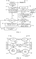
FIG. 1 is a general diagram of a particular illustrative embodiment of a system including multiple devices at various distances from a transmitter and graphically depicting wireless charging of two of the devices without time division as compared to wireless charging of the two device using time division based wireless charging; -
FIG. 2 is a block diagram of a particular illustrative embodiment of components of a receiver and a transmitter configured to perform time division wireless power transfer; -
FIG. 3 is a block diagram of a particular illustrative embodiment of components of the receiver ofFIG. 2 ; -
FIG. 4 is a flow chart of a particular illustrative embodiment of a method of time division wireless charging performed by a receiver and a transmitter; andFIG. 5 is a diagram of a particular embodiment of states of a control mechanism of a transmitter and a receiver of a time division wireless charging system. - Systems and methods are disclosed that enable power regulation during wireless power transfer, such as during magnetic resonance (MR) charging of multiple devices from a transmitter to reduce a charging imbalance of more distant receivers as compared to receivers located near the transmitter in a MR charging system. As other examples, power regulation during wireless power transfer may be applied to a powering system (e.g., supplying power from a transmitter to multiple devices that do not have a rechargeable battery) or a power restoring system.
-
FIG. 1 illustrates a particular embodiment of asystem 100 includingmultiple devices transmitter 102. The first device 104 (e.g. a mobile phone on its side) is coupled to afirst receiver 106 configured to charge a battery of thefirst device 104 using power received via MR from thetransmitter 102. Thesecond device 114 is coupled to asecond receiver 116 configured to charge a battery of thesecond device 114 using power received via MR from thetransmitter 102. Thethird device 124 is coupled to athird receiver 126 configured to charge a battery of thethird device 124 using power received via MR from thetransmitter 102. - Although each of the
devices devices distance transmitter 102 and a center of therespective receiver first device 104 has theshortest distance 108 and thethird device 124 has thelongest distance 128. - A
first graph 130 illustrates aMR charging characteristic 132 of thefirst device 104 that is nearer thetransmitter 102 and acharging characteristic 134 of thesecond device 114 that is further from thetransmitter 102. Thefirst device 104 receives more power and charges faster than thesecond device 114. After thefirst device 104 is fully charged, thefirst device 104 may disconnect from charging (e.g. thereceiver 106 may go "out of resonance"), enabling thesecond device 114 to increase a charging rate due to more power being available to thesecond device 114. - An approach that uses the concept of flickering to reduce the level of energy consumed by a nearer device and releasing that energy to other devices, but in a different way and using different means, is proposed. Although magnetic resonance technology, for example, is a means to transfer energy, the proposed approach is not limited to MR technology and in other implementations time-division wireless charging may be performed using another energy transfer technology.
- MR technology allows disconnecting of the Rx devices, by taking the Rx devices out of resonance, making the Rx devices "transparent" to the source Tx. The
first graph 130 illustrates a straight forward solution, for example of two mobile phones that both are charged: the closer device charged with higher power and the second device (at a farther distance from a shared transmitter) charged with less power, until the first device is fully charged and disconnects itself. The first device disconnecting itself enables the second device to receive more power and complete charging at an increased rate as compared to prior to the first device disconnecting. Although both devices will eventually get charged, a latency for the second device to reach a significant charge level is much greater than for the first device, because as the second device may have to 'wait' for the first device to fully charge and disconnect before the second device can charge at an increased charging rate. - In other implementations, multiple transmitters Tx may be used with multiple power channels, via different resonance frequencies, each Tx supporting one Rx and including a communication protocol between the Rx and Tx to control power strength. Such systems may be more expensive and complicated as compared to the time division charging illustrated in a
second graph 140. - The
second graph 140 illustrates a time division regulatedMR charging characteristic 142 of thefirst device 104 that is nearer thetransmitter 102 and a time division regulatedMR charging characteristic 144 of thesecond device 114 that is further from thetransmitter 102. Thefirst device 104 receives more power and charges faster than thesecond device 114 during a first representative time period 146. During a secondrepresentative time period 148, thefirst device 104 may disconnect from charging (e.g. thereceiver 106 may go "out of resonance"), enabling thesecond device 114 to increase a charging rate due to more power being available to thesecond device 114. As a result, the battery charge level of thefirst device 104 and thesecond device 114 are more evenly balanced than in the non-time division MR charging depicted in thefirst graph 130. - A battery charge level of each
device first device 104 and thesecond device 114 more evenly in thesecond graph 140 than in thefirst graph 130. For example, in thesecond graph 140, when thefirst device 104 is approximately 80% charged, thesecond device 114 is approximately 70% charged, compared to thefirst graph 130 when thefirst device 104 is approximately 80% charged, thesecond device 114 is approximately 20% charged. - Time division can be used to regulate the power between multiple devices with fairly minimal management and communication layers.
- By going 'out of resonance' the devices (Rx) may remove themselves from the power scheme, temporarily ceasing to draw power and allowing more power to be received by the other device(s). By flickering by disappearing (going out of resonance) and reappearing (returning into resonance) again and again, the device may regulate the amount of power that the device receives and that other devices receive at a ratio of a duration the device appears divided by a total duration of a disappear-reappear cycle (e.g. a length of the first time period 146 divided by a total length of the first time period 146 and the
second time period 148. - Communication and control methods are disclosed to optimize and improve this technique.
- A basic concept is to use the ability of the Rx to de-resonant and become transparent, leaving more power for the second device. Having the first device flicker at a constant or variable duty cycle may regulate the power draw of the first device, enabling more power to be received by the second device. In addition, having the first device flicker at a constant or variable duty cycle may regulate the power received by the first device to a lower level than is being transmitted.
- Optionally, a variable duty cycle may be employed and may be set, for example, from a largest duty cycle of 50% of connected time and reduced to a lower duty cycle as the battery charge level increases. For example, when the first device battery charge level is 60% the first device may use 50% duty cycle, drawing approximately half of the available energy. When the battery reaches 80% the first device may reduce to 40% duty cycle (e.g. drawing approximately 40% of the available energy), and then when reaching 95% the device may draw approximately 10% power by using a 10% duty cycle.
- A mechanism to smooth-out the flickering effect via a flickering spike absorbing means, such as an energy absorbing circuit, should be added to reduce the flickering spikes and to better shape power transfer by smoothing (or leveling) out the power level transmitted from the receiver power output (e.g. a power output of the receiver that is coupled to provide power to charge a battery of a mobile phone), as described in further detail with respect to
FIG. 3 . An energy absorbing means could be, for example, a snubber circuit consisting of a capacitor and, preferably, also a series resistor connected across the flickering circuit and configured for reducing and/or eliminating voltage spikes from voltage transient and ringing the flickering creates. A high peak current rated capacitor and a series resistor that is a non-inductive, carbon composition or carbon film resistor might work better. Alternatively, depending on the flickering circuit configuration a suppressor diode, such as a Schottky diode, might also be suitable. As an alternative to a Schottky diode, a Zener diode circuit may be used in connection with regulating/minimizing voltage spikes. -
FIG. 2 depicts a particular embodiment of asystem 200 including areceiver 202 and atransmitter 242 configured to perform time division wireless power transfer. For example, thetransmitter 242 may correspond to thetransmitter 102 ofFIG. 1 and thereceiver 202 may correspond to thereceiver 106 ofFIG. 1 . - The
transmitter 242 includes aresonant transmitter coil 244, a power stage amplifier andoscillator 246 coupled to theresonant transmitter coil 244, and apower supply circuit 248 coupled to the power stage amplifier andoscillator 246. Acontroller 250 is coupled to the power stage amplifier andoscillator 246 and to a communication interface (I/F) 252. - The
power supply circuit 248 may be configured to receive external power, such as from a direct current (DC) power supply (e.g. a battery), an alternating current (AC) power supply (e.g. a wall socket), or a combination thereof. Thepower supply circuit 248 is configured to provide power to the power stage amplifier andoscillator 246. - The power stage amplifier and
oscillator 246 may be configured to convert received power from thepower supply circuit 248 to oscillating current through theresonant transmitter coil 244. The power stage amplifier andoscillator 246 may be responsive to thecontroller 250 to adjust an amount ofpower 270 that is provided via amagnetic field 272 generated by theresonant transmitter coil 244. For example, the power stage amplifier andoscillator 246 may be responsive to thecontroller 250 to adjust an amplitude, a frequency, or both, of alternating current through theresonant transmitter coil 244. - The
controller 250 may be configured to be responsive to messaging received via thecommunication interface 252, such as described with respect toFIGs. 4-5 . For example, in response to thecontroller 250 receiving an indication that one or more receivers request an increase of thepower 270, thecontroller 250 may instruct the power stage amplifier andoscillator 246 to adjust operation to increase thepower 270. As another example, in response to thecontroller 250 receiving an indication that one or more receivers are no longer receiving the power 270 (e.g. a receiver has dropped out of resonance), thecontroller 250 may instruct the power stage amplifier andoscillator 246 to adjust operation to decrease thepower 270. - The
communication interface 252 may enable thetransmitter 242 to receive wireless signaling, such as arepresentative communication 274, from one or more other devices. To illustrate, thecommunication interface 252 may include an antenna and radio-frequency circuitry to enable wireless communication, such as via a short-range ad-hoc wireless network (e.g. Bluetooth), as an illustrative, non-limiting example. In an embodiment not specifically shown inFIG. 2 , thecommunication interface 252 may enable thetransmitter 242 to send wireless signals to one or more other devices, such as to instruct one or more receivers to initiate flickering to enable time-division wireless charging of multiple receivers, as one illustrative example, or to cease flickering, as another illustrative example. - The
receiver 202 includes aresonant receiver coil 204 coupled to a signal rectification andsnubber circuit 206 and to a controlledoscillator 212. The signal rectification andsnubber circuit 206 is coupled to provide power to aload 260 via avoltage feedback stage 208. Acontroller 210 is coupled to thevoltage feedback stage 208, to the controlledoscillator 212, and to acommunication interface 214. - The controlled
oscillator 212 may include circuit components such as capacitive components, inductive components, resistive components, or any combination thereof, that enable resonant (or near-resonant) oscillation of theresonant receiver coil 204 to receive at least a portion of thepower 270 from thefield 272. The controlledoscillator 212 is responsive to thecontroller 210 to "flicker," i.e. to alternately enable and disable resonant oscillation of theresonant receiver coil 204. For example, the controlledoscillator 212 may include one or more switching components to increase or decrease a capacitance encountered by a current flow through theresonant receiver coil 204 to adjust a resonant frequency of theresonant receiver coil 204. As another example, thecontroller oscillator 212 may include a switch to block current flow into and/or out of theresonant receiver coil 204. - The signal rectification and
snubber circuit 206 may be configured to rectify an alternating current received from theresonant receiver coil 204 and to reduce or eliminate any flickering spikes and to shape power transfer by smoothing (or leveling) out the power level transmitted from areceiver power output 258 to theload 260. An example of components of the signal rectification andsnubber circuit 206 is illustrated inFIG. 3 . - The
voltage feedback stage 208 may provide a power output to theload 260 and may enable feedback to be provided to thecontroller 210. For example, the feedback can indicate a magnitude of power transfer to the load 260 (e.g. a rate of battery charging). As another example, the feedback can indicate a power status received from theload 260, such as a battery fully charged indication. - The
controller 210 may be configured to control operation of the controlledoscillator 212 in response to feedback from thevoltage feedback stage 208, in response to one or more communications received via thecommunication interface 214, or any combination thereof. For example, in response to receiving an instruction from thetransmitter 242 to initiate flickering according to a specified duty cycle, thecontroller 210 may be configured to send signals to cause the controlledoscillator 212 to enter resonance or to go out of resonance according to the specified duty cycle. Thecontroller 210 may also be configured to initiate wireless communication with thetransmitter 242, such as by instructing thecommunication interface 214 to send a representative communication 274 (e.g. in response to thevoltage feedback stage 208 indicating that the received portion of thepower 270 is below a threshold charging amount). - Although
FIG. 2 depicts an illustrative example of components of a wireless power transfer system, in other implementations one or more components of thesystem 200 may differ from the example described with respect toFIG. 2 . To illustrate, in some implementations thecommunication interface 252 may use theresonant receiver coil 204 to send and/or receive communications with thetransmitter 242. For example, theresonant receiver coil 204 may be used as an antenna for radio-frequency communications. As another example, theresonant receiver coil 204 may be used to modulate thefield 272 to convey information to thetransmitter 242. -
FIG. 3 illustrates aparticular embodiment 300 of components of thereceiver 202 ofFIG. 2 . Theresonant receiver coil 204 is illustrated serially coupled to the controlledoscillator 212. A snubber circuit 310 (of the signal rectification and snubber circuit 206 ) is coupled in parallel with the controlledoscillator 212. Arectifier 320 is coupled to receive an input signal from theresonant receiver coil 204 and responsive to the controlledoscillator 212 to provide a rectified output signal at an output 330 (e.g. to the load 260). For example, therectifier 320 may include a full-wave diode bridge with a smoothing capacitor. - The
snubber circuit 310 is illustrated as including a capacitive component 302 (e.g. a capacitor) serially coupled to a resistive component 304 (e.g. a resistor) to reduce voltage spikes or other effects that may occur in response to the controlledoscillator 212 enabling or disabling resonant current oscillation through theresonant receiver coil 204. Thesnubber circuit 310 is also illustrated as including adiode element 306, such as a Schottky diode or a Zener diode, coupled in parallel across the controlledoscillator 212. Although thesnubber circuit 310 is illustrated as including a resistor-capacitor (RC) path (i.e., a current path through theresistive component 304 and the capacitive component 302) and a diode path (i.e., a current path through the diode 306), in other implementations thesnubber circuit 310 may include only one of the RC path and the diode path. Alternatively, thesnubber circuit 310 may include one or more other types of circuit components (e.g. a resistor-inductor-capacitor (RLC) circuit). Alternatively, thesnubber circuit 310 could be placed at other locations of thereceiver 202, such as at theoutput 330. - Multiple alternatives for the charging regulation mechanism of the systems of
FIGs. 1-2 exist. Below are a few examples. - One alternative that is not in itself in accordance with the invention as claimed uses a standard separate communication layer between the Rx's and Tx. The communication layer allows the Rx to report the Tx for: charging power is OK (message [OK]), request to increase Tx power (message [I]), done, and about to disconnect (message [D]). As an example, in an implementation where two Rx's are at different distances from one Tx, when the Tx receives [I] the Tx will increase its power to deliver more power. If both Rx devices are OK (e.g. the Tx receives [OK] from both devices), the Tx will keep sending power until all devices have sent [D].
- If the Tx reaches a power threshold, such as max power, and receives an [I] request, the Tx will send a message (e.g., indicating that the Tx is transmitting at max power (message [MaxP])). When an Rx receives [MaxP], if the Rx's status is OK (e.g. sending [OK] to the Tx), the Rx will flicker its resonance existence (i.e. will alternately disconnect and re-connect) to enable the other Rx device to get more power. When a Rx receives [MaxP], if the Rx's status is [I] (e.g. sending [I] to the Tx), the Rx will maintain the [I] status as long as the Tx transmits [MaxP].
- An Rx that reaches a charged battery level will disconnect. If the Tx is able to detect only one device at charging (i.e. only one Rx), the Tx will stop messaging [MaxP] so that the Rx that needed more power is able to re-evaluate its power need (e.g. [I] or [OK]).
- For an Rx that is not flickering, the Rx will determine its status of [OK], [I] or [D] by averaging the energy it receives during multiple cycles. For an Rx that is flickering, a status of [OK] is designated even if the decreased level of power due to the flickering would otherwise cause the Rx to send [I] to the Tx. For example, when an average level of power is at or above a charging rate threshold, a status of [OK] may be designated. When an average level of power is below the charging rate threshold, a status of [I] may be designated. For a Rx that is flickering, a status of [I] is not designated even if the average level of power due to the flickering would otherwise cause the Rx to send [I] to the Tx and instead a status of [OK] is designated.
- The implementation uses the Tx as the central decision point to provide power according to the aggregated needs of the Rx and to instruct particular receivers Rx to use flickering mode.
FIG. 4 depicts a flow diagram of a particular illustrative embodiment of a method of time division wireless charging 402 performed by a receiver and a method of time division wireless charging 404 performed by a transmitter. - The method of time division wireless charging 402 performed by the receiver (Rx) includes sensing a transmitter (Tx) field, at 412. The Rx identifies itself to the Tx, at 414, such as by sending identification information to the Tx. In response to receiving an acknowledgement (Ack) from the Tx, the Rx communicates to the Tx power feedback information regarding requested or required power of the Rx as compared to received power, at 416. The Rx may determine whether the Rx requires more power, at 418. In response to determining that the Rx requires more power, at 418, processing returns to 416 where the Rx communicates power feedback information to the Tx. Otherwise, if the Rx does not require more power, at 418, the Rx gets out of resonance (e.g. "disappears"), at 420.
- The Rx may start flickering (i.e. alternately enter resonance and exiting resonance) with a requested duty cycle, at 422. For example, the Rx may receive a message from the Tx suggesting a flickering duty cycle. After entering a flickering charging mode, processing returns to make a determination whether more power is needed, at 418.
- The method of time division wireless charging 404 performed by the transmitter (Tx) includes identifying a Rx and sending an acknowledgement (Ack), at 432. For example, the acknowledgement may be sent in response to receiving an identification message from the Rx. A determination may be made, for each Rx identified at the Tx, whether the Tx has received any communication from the Rx within a particular time period, such as whether any message is received from a particular Rx within a threshold number of seconds after a last communication was received from, or sent to, the particular Rx. In response to determining that no communication has been received from a particular Rx within the time period, at 434, the Tx may ignore the particular Rx and function as the Rx has disappeared (e.g. has been turned off, removed from within a charging range of the Tx, or has completed charging and left resonance, as illustrative examples).
- The Tx determines whether to maintain power, provide more power, or provide less power, based on aggregated requirements of the Rx device(s) that have been received by the Tx, at 438. If total required and/or requested power of the Rx device(s) exceeds a maximum power output of the Tx, at 440, the Tx may send a message suggesting a flickering duty cycle, at 442. For example, the Tx may address the message to a particular Rx. As another example, the Tx may broadcast the message and each Rx may self-determine whether to enter a flickering mode according to the suggested duty cycle (e.g. if the Rx is receiving satisfactory power, and/or sent an [OK] message, the Rx may enter a flickering mode).
-
FIG. 5 illustrates a particular embodiment of states of acontrol mechanism 502 of a transmitter of a time division wireless charging system and states of a control mechanism of areceiver 504 of a time division wireless charging system. - The
states 502 of the transmitter include:
Search 512: the Tx transmits a signal allowing the Rx to discover the Tx and to be discovered by the Tx. For example, the Tx may send a ping signal. - Detection 514: the Tx receives an identification of a Rx and an indication of received power strength as compared to a required power strength of the Rx (i.e. the Tx receives a message indicating a difference between received power and required power at a Rx). Upon the Tx detecting a Rx, the Tx will send power to enable charging of the Rx.
- Power Adjust and Feedback 516: The Tx analyzing power feedback information from the Rx(s) may adjust the power strength and may send a request for one or more of the receivers Rx(s) to flicker. An example for logic that may be used is described in additional detail below. The Tx transitions from the Power Adjust and
Feedback state 516 to the Rx Detectedstate 514 to re-evaluate the power usage. - The
states 504 of the receiver include: - Search 532: the Rx listens for a ping signal from the Tx
- ID and Status 534: The Rx transmits identification information and power feedback information, such as data indicating required power and received power.
- Use Power and Adjust 536: The Rx uses received power (e.g. to charge a battery). In response to receiving a request from the Tx to enter a flickering mode or to adjust a flicker duty cycle, the Rx may comply with the request of the Tx. The Rx returns from the Use Power and Adjust
state 536 to the ID andStatus state 534 to re-evaluate its power usage. - In case of no-signal being received following a defined time-out, the Tx or Rx will transition back to the
Search state - The logic that is implemented by the Tx at the power adjustment phase includes:
- 1. The Tx aggregates the devices power requirements (Rxr)
- 2. If all the Rxr are coherent (i.e. unanimous) requests to increase or decrease power, then:
a. Tx will follow, increasing power proportionally to the evaluated difference reported by the devices request. - 3. If at least one device requires more power while other devices are OK or need more power as well, then:
- a. The Tx will evaluate which device needs the most power, the one with the biggest difference between the received and desired power (referred to as "device A"),
- b. The Tx will increase power such that the increase in power is proportional to a difference between received versus desired power of device A.
- c. The Tx directs the other devices to flicker at a duty cycle that will maintain the same energy received at each Rx as before the power increase. Such duty cycle will be the inverse of the proportion of the added strength. (For example: Tx increases power from T1 to T2, then it is expected that the Rx will receive power of R2 = R1 ∗ T2/T1. The duty cycle Rx should be used to maintain a similar energy level as 1/(T2/T1)= T1/T2.)
- 4. If Tx reaches a power threshold (e.g., MAX POWER) and at least one device requires more power, then
- a. Direct the devices with the minimal gap between received and desired power to flicker at a duty cycle that attempts to even out the devices' proportions between the desired and received energy. The approximate calculation for such optimization is system dependent. The other devices may flicker at a same duty cycle or at different duty cycles.
- If more information exists, for example the level of Rx battery charged, then improved charging balancing between devices may be reached.
- In conjunction with the disclosed embodiments, a method may be performed in a wireless charging receiver. The method includes receiving a power usage indication from a wireless charging transmitter. For example, the power usage message may be a [MaxP] message indicating that the wireless charging transmitter is transmitting at a maximum power. As another example, the power usage message may be a message requesting receiver flickering and indicating a suggested duty cycle.
- In response to receiving the power usage indication, the wireless charging receiver enters a power receiving mode and exits the power receiving mode according to a duty cycle. For example, the first device 146 enters the power receiving mode upon entering the first time period 146 of
FIG. 1 and exits the power receiving mode upon entering thesecond time period 148 ofFIG. 1 . Entering the power receiving mode can include entering a magnetic resonance state to receive power from a magnetic resonance transmitter. Exiting the power receiving mode can include exiting the magnetic resonance state, or going "out of resonance." In some implementations power may be received by the wireless charging receiver when not in the power receiving mode at a significantly reduced rate as compared to power reception in the power receiving mode. - Exiting the power receiving mode increases an amount of transmitted power that is available to be received by one or more other wireless charging receivers. The wireless charging receiver may include an energy absorbing circuit configured to reduce voltage spikes in an output of the wireless charging receiver that result from entering and exiting the power receiving mode. As an example, the energy absorbing circuit may include a capacitor coupled to a series resistor. As another example, the energy absorbing circuit may include a Schottky diode and/or a Zener diode.
- A method may be performed in a wireless charging transmitter, such as the
transmitter 102 ofFIG. 1 . The method may include transmitting power to be received by at least a first wireless charging receiver and a second wireless charging receiver. The wireless charging transmitter may send a message to the first wireless charging receiver to exit a power receiving mode. Sending the message to the first wireless device may enable more power to be provided to the second wireless device while the first wireless devices is not in the power receiving mode. The message may cause the first wireless charging receiver to enter the power receiving mode after temporarily exiting the power receiving mode, such as according to a duty cycle. - Although various components depicted herein are illustrated as block components and described in general terms, such components may include one or more microprocessors, state machines, or other circuits configured to enable the
transmitter 102 and thedevices receivers FIG. 1 to operate according to a time-division wireless charging protocol. For example, physical components, such as hardware controllers, state machines, logic circuits, or other structures, may be used to enable thereceiver 106 ofFIG. 1 to operate according to themethod 402 ofFIG. 4 and/or according to the operating states 504 ofFIG. 5 . As another example, physical components, such as hardware controllers, state machines, logic circuits, or other structures, may be used to enable thetransmitter 102 ofFIG. 1 to operate according to themethod 404 ofFIG. 4 and/or according to the operating states 502 ofFIG. 5 . - The illustrations of the embodiments described herein are intended to provide a general understanding of the various embodiments. Other embodiments may be utilized and derived from the disclosure, such that structural and logical substitutions and changes may be made without departing from the scope of the disclosure. This disclosure is intended to cover any and all subsequent adaptations or variations of various embodiments. The scope of the invention being defined by the appended claims.
Claims (6)
- A method of regulating wireless charging of a plurality of power receiving systems in a wireless charging system comprising a wireless power transfer system and a plurality of wireless power receiving systems, each wireless power receiving system comprising a controlled oscillator (212) configured to be coupled to a resonant receiver coil (204), the method comprising:one or more of the wireless power receiving systems wirelessly providing, to the wireless power transfer system (102, 242), a message indicating a difference between received power and requested power at the wireless power receiving system (104, 114, 124, 202);the wireless power transfer system increasing a transmitted power of the power transfer system (102, 242) in proportion to the differences between received power and requested power at the wireless power receiving systems (104, 114, 124, 202) indicated in the messages;the method further comprising:the wireless power transfer system, if the total requested power of the wireless power receiving systems (104, 114, 124, 202) indicated in the messages exceeds a maximum power output of the wireless power transfer system, sending to at least one of the wireless power receiving systems a message requesting the wireless power receiving system alternating between a power transfer mode and a non-power transfer mode and indicating a duty cycle for the alternating between a power transfer mode and a non-power transfer mode;and the at least one of the wireless power receiving systems in response to receiving the message from the wireless power transfer system (102, 242), alternating the wireless power receiving system (104, 114, 124, 202) between a power transfer mode and a non-power transfer mode based on the indication of a duty cycle provided by the wireless power transfer system (102, 242) to the wireless power receiving system (104, 114, 124, 202);wherein when the wireless power receiving system (104, 114, 124, 202) is in the non-power transfer mode, the wireless power receiving system consumes substantially no power wirelessly transferred from the wireless power transfer system (102, 242), thereby increasing the amount of transmitted power that is available to be received by one or more other ones of the wireless power receiving systems.
- The method of claim 1, comprising:a plurality of the wireless power receiving systems wirelessly providing, to the wireless power transfer system (102, 242), a message indicating a difference between received power and requested power at the wireless power receiving system (104, 114, 124, 202);andif all of the plurality of the wireless power receiving systems provide a message
indicating a request to increase power:the wireless power transfer system increasing a transmitted power of the power transfer system (102, 242) in proportion to the differences between received power and requested power at the wireless power receiving systems (104, 114, 124, 202) indicated in the messages from the plurality of the wireless power receiving systems;andif at least one of the plurality of the wireless power receiving systems provides a message indicating a request to increase power, while others of the plurality of the wireless power receiving systems provides a message indicating that they are okay or need more power as well:
the wireless power transfer system:evaluating the wireless power receiving system that has the highest indicated difference between received power and requested power;increasing a transmitted power of the power transfer system (102, 242) in proportion to the difference between the indicated received power and requested power at the wireless power receiving system (104, 114, 124, 202) evaluated as having the highest indicated difference between received power and requested power; andsubsequent to increasing the transmitted power, providing an updated duty cycle to the others of the plurality of wireless power receiving systems (104, 114, 124, 202), the updated duty cycle maintaining the same received power at the others of the plurality of wireless power receiving systems as prior to increasing the transmitted power. - A wireless charging system comprising:a wireless power transfer system (102, 242);a plurality wireless power receiving systems (104, 114, 124, 202), each wireless power receiving system including:a controller (210);a communication interface (214); anda controlled oscillator (212) configured to be coupled to a resonant receiver coil (204);characterised in that:the controller (210) is configured to:
wirelessly provide, to the wireless power transfer system (102, 242), a message indicating a difference between received power and requested power at the wireless power receiving system (104, 114, 124, 202);the wireless power transfer system (102, 242) is operable to increase a transmitted power in proportion to the difference between received power and requested power at the wireless power receiving systems (104, 114, 124, 202) indicated in messages received from the wireless power receiving systems; andthe wireless power transfer system is further operable to, if the total requested power of the wireless power receiving systems (104, 114, 124, 202) indicated in the messages exceeds a maximum power output of the wireless power transfer system, send to at least one of the wireless power receiving systems a message requesting the wireless power receiving system alternating between a power transfer mode and a non-power transfer mode and indicating a duty cycle for the alternating between a power transfer mode and a non-power transfer mode;the controller of each wireless power receiving system is configured to in response to receiving a message from the wireless power transfer system (102, 242), cause the controlled oscillator (212) to alternate between a power transfer mode and a non-power transfer mode based on an indication of a duty cycle provided by the wireless power transfer system (102, 242) to the wireless power receiving system; andwhen the wireless power receiving system (104, 114, 124, 202) is in the non-power transfer mode, the controller (210) is further configured to cause the wireless power receiving system (104, 114, 124, 202) to consume substantially no power wirelessly transferred from the wireless power transfer system (102, 242), thereby increasing the amount of transmitted power that is available to be received by one or more other ones of the wireless power receiving systems. - The wireless charging system (104, 114, 124, 202) of claim 3, wherein each wireless power receiving system further comprises an energy absorbing circuit (310).
- The wireless charging system (104, 114, 124, 202) of claim 4, wherein each energy absorbing circuit (310) includes a capacitor (302) coupled to a series resistor (304).
- The wireless charging system (104, 114, 124, 202) of claim 4, wherein each energy absorbing circuit (310) includes at least one of a Schottky diode and a Zener diode.
Applications Claiming Priority (3)
| Application Number | Priority Date | Filing Date | Title |
|---|---|---|---|
| US201261597278P | 2012-02-10 | 2012-02-10 | |
| US13/486,772 US9018898B2 (en) | 2012-02-10 | 2012-06-01 | Regulation of wirelessly charging multiple devices from the same source |
| PCT/US2013/022897 WO2013119395A1 (en) | 2012-02-10 | 2013-01-24 | Regulation of wirelessly charging multiple devices from the same source |
Publications (2)
| Publication Number | Publication Date |
|---|---|
| EP2815481A1 EP2815481A1 (en) | 2014-12-24 |
| EP2815481B1 true EP2815481B1 (en) | 2020-06-24 |
Family
ID=48945053
Family Applications (1)
| Application Number | Title | Priority Date | Filing Date |
|---|---|---|---|
| EP13705628.9A Active EP2815481B1 (en) | 2012-02-10 | 2013-01-24 | Regulation of wirelessly charging multiple devices from the same source |
Country Status (3)
| Country | Link |
|---|---|
| US (1) | US9018898B2 (en) |
| EP (1) | EP2815481B1 (en) |
| WO (1) | WO2013119395A1 (en) |
Families Citing this family (45)
| Publication number | Priority date | Publication date | Assignee | Title |
|---|---|---|---|---|
| WO2013031054A1 (en) * | 2011-08-31 | 2013-03-07 | Necカシオモバイルコミュニケーションズ株式会社 | Charging system, electronic apparatus, charge control method, and program |
| JP5649603B2 (en) * | 2012-03-21 | 2015-01-07 | 株式会社東芝 | Power transmission device and power transmission method |
| US9218031B2 (en) * | 2012-05-18 | 2015-12-22 | Dell Products, Lp | System and method for providing wireless power feedback in a wireless power delivery system |
| KR102074475B1 (en) | 2012-07-10 | 2020-02-06 | 지이 하이브리드 테크놀로지스, 엘엘씨 | Apparatus and method for detecting foreign object in wireless power transmitting system |
| US20150244199A1 (en) * | 2012-09-11 | 2015-08-27 | Yulong Computer Telecommunication Technologies (Shenzhen) Co., Ltd. | Wireless charger and multi-terminal wireless charging method |
| US20140159673A1 (en) * | 2012-12-07 | 2014-06-12 | Samsung Electronics Co., Ltd. | Wireless charging apparatus and method |
| JP2014183628A (en) * | 2013-03-18 | 2014-09-29 | Canon Inc | Communication apparatus, control method of the same, and program |
| US9847666B2 (en) | 2013-09-03 | 2017-12-19 | Apple Inc. | Power management for inductive charging systems |
| US9837866B2 (en) | 2013-10-09 | 2017-12-05 | Apple Inc. | Reducing power dissipation in inductive energy transfer systems |
| US20190089183A9 (en) * | 2013-10-23 | 2019-03-21 | Apple Inc. | Transmitter and receiver communication for inductive power transfer systems |
| KR20150050027A (en) * | 2013-10-31 | 2015-05-08 | 삼성전기주식회사 | Wireless charging device and controlling method thereof |
| US9673784B2 (en) | 2013-11-21 | 2017-06-06 | Apple Inc. | Using pulsed biases to represent DC bias for charging |
| US9893553B2 (en) | 2013-12-24 | 2018-02-13 | Pavan Pudipeddi | Method and system for simultaneously wirelessly charging portable rechargeable devices based on wireless inductive power transfer with seamless free positioning capability |
| US9882419B2 (en) | 2014-02-14 | 2018-01-30 | Massachusetts Institute Of Technology | Adaptive control of wireless power transfer |
| US9800076B2 (en) | 2014-02-14 | 2017-10-24 | Massachusetts Institute Of Technology | Wireless power transfer |
| CN103972993A (en) | 2014-04-23 | 2014-08-06 | 北京智谷睿拓技术服务有限公司 | Wireless energy transmission method and wireless energy transmission device |
| CN103944282B (en) | 2014-04-23 | 2016-07-27 | 北京智谷睿拓技术服务有限公司 | Wireless energy transfer method and wireless energy send equipment |
| CN103944283B (en) | 2014-04-23 | 2016-10-05 | 北京智谷睿拓技术服务有限公司 | Wireless energy transfer method and wireless energy send equipment |
| KR20160051497A (en) * | 2014-11-03 | 2016-05-11 | 주식회사 한림포스텍 | Method and apparutus for controlling a power transmission coverage of wireless power transmission network |
| WO2016099032A1 (en) | 2014-12-16 | 2016-06-23 | 주식회사 한림포스텍 | Apparatus and method for controlling power transmission coverage of wireless power transmission network |
| US10503939B2 (en) * | 2014-12-24 | 2019-12-10 | Intel Corporation | Method and apparatus for energy harvest from a proximity coupling device |
| WO2016108949A1 (en) | 2014-12-31 | 2016-07-07 | Massachusetts Institute Of Technology | Adaptive control of wireless power transfer |
| WO2016164790A1 (en) | 2015-04-10 | 2016-10-13 | Ossia Inc. | Wireless power transceivers for supplementing wireless power delivery and extending range |
| WO2016185693A1 (en) * | 2015-05-19 | 2016-11-24 | パナソニックIpマネジメント株式会社 | Non-contact power supplying appliance and non-contact power receiving appliance, and non-contact power transmitting system provided therewith |
| US9915988B2 (en) | 2015-09-22 | 2018-03-13 | Sandisk Technologies Llc | Data storage device for a device accessory |
| US10122217B2 (en) | 2015-09-28 | 2018-11-06 | Apple Inc. | In-band signaling within wireless power transfer systems |
| US20170373522A1 (en) * | 2016-06-23 | 2017-12-28 | Apple Inc. | Charging System |
| US10601250B1 (en) | 2016-09-22 | 2020-03-24 | Apple Inc. | Asymmetric duty control of a half bridge power converter |
| US10790703B2 (en) * | 2016-12-19 | 2020-09-29 | Koji Yoden | Smart wireless power transfer between devices |
| US10978899B2 (en) | 2017-02-02 | 2021-04-13 | Apple Inc. | Wireless charging system with duty cycle control |
| CN111869045B (en) * | 2018-03-08 | 2024-04-16 | 利奇电力公司 | Method and system for wireless power transfer |
| WO2020047663A1 (en) | 2018-09-05 | 2020-03-12 | Dpm Technologies Inc. | Systems and methods for intelligent energy storage and provisioning using an energy storage control system |
| CN109383315B (en) * | 2018-11-14 | 2020-10-23 | 常熟理工学院 | Mutual inductance estimation method for multi-transmitting-end/single-receiving-end wireless charging system |
| KR102706914B1 (en) * | 2019-09-03 | 2024-09-19 | 삼성전자주식회사 | Method for wireless charging and electronic device supporting the same |
| US20220302729A1 (en) * | 2019-11-08 | 2022-09-22 | Hewlett-Packard Development Company, L.P. | Charge determination |
| KR102914038B1 (en) * | 2020-02-10 | 2026-01-16 | 삼성전자주식회사 | Power receiving device and method for controlling a charging current |
| KR102672310B1 (en) * | 2020-05-06 | 2024-06-05 | 한국전자통신연구원 | System and method for wireless power transmission |
| US11888334B2 (en) * | 2020-10-27 | 2024-01-30 | Caterpillar Inc. | Methods and systems for charging or discharging energy storage systems |
| EP4220893A4 (en) * | 2020-10-28 | 2024-07-31 | Aeterlink Corp. | POWER RECEIVING DEVICE AND POWER TRANSMISSION DEVICE BASED ON WIRELESS POWER SUPPLY METHOD |
| US11611242B2 (en) | 2021-04-14 | 2023-03-21 | Reach Power, Inc. | System and method for wireless power networking |
| TWI794795B (en) * | 2021-04-26 | 2023-03-01 | 國立陽明交通大學 | Inductive resonant wireless charging system, resonant wireless charging transmitting device, wireless charging relay device and inductive wireless charging receiving device |
| WO2022232904A1 (en) * | 2021-05-04 | 2022-11-10 | Exro Technologies Inc. | Battery control systems and methods |
| CN117337545A (en) | 2021-05-13 | 2024-01-02 | Exro技术公司 | Method and device for driving coils of polyphase motors |
| CA3223051A1 (en) | 2021-07-08 | 2023-01-12 | Eric HUSTEDT | Dynamically reconfigurable power converter utilizing windings of electrical machine |
| US12595932B2 (en) * | 2022-11-11 | 2026-04-07 | Rheem Manufacturing Company | Systems and methods for powering water heating devices using wireless power transmissions |
Citations (2)
| Publication number | Priority date | Publication date | Assignee | Title |
|---|---|---|---|---|
| US20090271048A1 (en) * | 2008-04-28 | 2009-10-29 | Masataka Wakamatsu | Power Transmitting Apparatus, Power Transmission Method, Program, and Power Transmission System |
| US20110006612A1 (en) * | 2009-07-07 | 2011-01-13 | Sony Corporation | Contactless power receiving apparatus, power receiving method for contactless power receiving apparatus and contactless power supplying system |
Family Cites Families (20)
| Publication number | Priority date | Publication date | Assignee | Title |
|---|---|---|---|---|
| US6160389A (en) * | 1999-08-27 | 2000-12-12 | Black & Decker Inc. | Battery charger with low heat dissipation |
| US8471642B2 (en) * | 2005-12-16 | 2013-06-25 | Cambridge Resonant Technologies Ltd. | Resonant circuits |
| US8159364B2 (en) * | 2007-06-14 | 2012-04-17 | Omnilectric, Inc. | Wireless power transmission system |
| US8428528B2 (en) * | 2007-10-24 | 2013-04-23 | Biotronik Crm Patent Ag | Radio communications system designed for a low-power receiver |
| WO2009089253A1 (en) | 2008-01-07 | 2009-07-16 | Access Business Group International Llc | Inductive power supply with duty cycle control |
| WO2009126963A2 (en) | 2008-04-11 | 2009-10-15 | University Of Florida Research Foundation, Inc. | Power control duty cycle throttling scheme for planar wireless power transmission system |
| US20090278493A1 (en) * | 2008-05-10 | 2009-11-12 | Alden Ray M | Intra-package battery charging apparatus and process for distributed products |
| US9130407B2 (en) | 2008-05-13 | 2015-09-08 | Qualcomm Incorporated | Signaling charging in wireless power environment |
| US8532724B2 (en) * | 2008-09-17 | 2013-09-10 | Qualcomm Incorporated | Transmitters for wireless power transmission |
| US8373386B2 (en) | 2009-01-06 | 2013-02-12 | Access Business Group International Llc | Wireless charging system with device power compliance |
| US8497658B2 (en) * | 2009-01-22 | 2013-07-30 | Qualcomm Incorporated | Adaptive power control for wireless charging of devices |
| US8970180B2 (en) * | 2009-04-07 | 2015-03-03 | Qualcomm Incorporated | Wireless power transmission scheduling |
| US8547057B2 (en) | 2009-11-17 | 2013-10-01 | Qualcomm Incorporated | Systems and methods for selective wireless power transfer |
| KR20110062841A (en) * | 2009-12-04 | 2011-06-10 | 한국전자통신연구원 | Wireless power transmitter |
| US9561730B2 (en) * | 2010-04-08 | 2017-02-07 | Qualcomm Incorporated | Wireless power transmission in electric vehicles |
| US9479225B2 (en) * | 2010-05-13 | 2016-10-25 | Qualcomm Incorporated | Resonance detection and control within a wireless power system |
| KR101760632B1 (en) * | 2010-05-19 | 2017-07-21 | 퀄컴 인코포레이티드 | Adaptive wireless energy transfer system |
| US8890470B2 (en) * | 2010-06-11 | 2014-11-18 | Mojo Mobility, Inc. | System for wireless power transfer that supports interoperability, and multi-pole magnets for use therewith |
| JP5755066B2 (en) * | 2010-07-30 | 2015-07-29 | 株式会社半導体エネルギー研究所 | Wireless power feeding system and wireless power feeding method |
| US9508487B2 (en) * | 2011-10-21 | 2016-11-29 | Qualcomm Incorporated | Systems and methods for limiting voltage in wireless power receivers |
-
2012
- 2012-06-01 US US13/486,772 patent/US9018898B2/en active Active
-
2013
- 2013-01-24 WO PCT/US2013/022897 patent/WO2013119395A1/en not_active Ceased
- 2013-01-24 EP EP13705628.9A patent/EP2815481B1/en active Active
Patent Citations (2)
| Publication number | Priority date | Publication date | Assignee | Title |
|---|---|---|---|---|
| US20090271048A1 (en) * | 2008-04-28 | 2009-10-29 | Masataka Wakamatsu | Power Transmitting Apparatus, Power Transmission Method, Program, and Power Transmission System |
| US20110006612A1 (en) * | 2009-07-07 | 2011-01-13 | Sony Corporation | Contactless power receiving apparatus, power receiving method for contactless power receiving apparatus and contactless power supplying system |
Also Published As
| Publication number | Publication date |
|---|---|
| US20130207599A1 (en) | 2013-08-15 |
| US9018898B2 (en) | 2015-04-28 |
| EP2815481A1 (en) | 2014-12-24 |
| WO2013119395A1 (en) | 2013-08-15 |
Similar Documents
| Publication | Publication Date | Title |
|---|---|---|
| US9018898B2 (en) | Regulation of wirelessly charging multiple devices from the same source | |
| US11303135B2 (en) | Wireless power transmitter for excluding cross-connected wireless power receiver and method for controlling the same | |
| US11552480B2 (en) | Method and power transmitter for controlling power transmission | |
| US10587123B2 (en) | Wireless power transmitter for excluding cross-connected wireless power receiver and method for controlling the same | |
| US9496083B2 (en) | Wireless power transmitter, wireless power receiver, and methods of controlling the same | |
| KR102051682B1 (en) | Apparatus and method for detecting foreign object in wireless power transmitting system | |
| US10790701B2 (en) | Wireless power transmitter, wireless power receiver, and control methods thereof | |
| CN109417309B (en) | Electronic device and method of communicating between wireless power receiving and transmitting devices | |
| US9379573B2 (en) | Power transmitter and method for controlling power transmission | |
| US20130200844A1 (en) | Wireless power charging method and apparatus | |
| US11271432B2 (en) | Wireless power control method and device | |
| KR102154306B1 (en) | Wireless power transmission device which enables to simultaneously charge | |
| JP2014082864A (en) | Power-receiving control circuit, method of controlling wireless power-receiving device, and electronic apparatus | |
| CN112421801A (en) | Wireless power transmitter and control method thereof | |
| US11228206B2 (en) | Wireless power transmitter, wireless power receiver, and control methods thereof | |
| KR20190134566A (en) | Apparatus and method for detecting foreign object in wireless power transmitting system | |
| JP2016152722A (en) | Semiconductor device and wireless power supply system | |
| KR20200022086A (en) | Wireless Power Transmission Method and Apparatus | |
| KR102230682B1 (en) | Wireless power transmission device which enables to simultaneously charge | |
| JP2018521623A (en) | Wireless power transmission method in wireless charging system including wireless power transmitter and wireless power receiver | |
| KR20210031668A (en) | Wireless power transmission device which enables to simultaneously charge | |
| JP6743234B2 (en) | Power receiving device, power transmitting device, power receiving device control method, power transmitting device control method, and program | |
| KR20230169045A (en) | Wireless power transmission device which enables to simultaneously charge |
Legal Events
| Date | Code | Title | Description |
|---|---|---|---|
| PUAI | Public reference made under article 153(3) epc to a published international application that has entered the european phase |
Free format text: ORIGINAL CODE: 0009012 |
|
| 17P | Request for examination filed |
Effective date: 20140908 |
|
| AK | Designated contracting states |
Kind code of ref document: A1 Designated state(s): AL AT BE BG CH CY CZ DE DK EE ES FI FR GB GR HR HU IE IS IT LI LT LU LV MC MK MT NL NO PL PT RO RS SE SI SK SM TR |
|
| AX | Request for extension of the european patent |
Extension state: BA ME |
|
| DAX | Request for extension of the european patent (deleted) | ||
| RAP1 | Party data changed (applicant data changed or rights of an application transferred) |
Owner name: SANDISK TECHNOLOGIES LLC |
|
| STAA | Information on the status of an ep patent application or granted ep patent |
Free format text: STATUS: EXAMINATION IS IN PROGRESS |
|
| 17Q | First examination report despatched |
Effective date: 20170801 |
|
| REG | Reference to a national code |
Ref country code: DE Ref legal event code: R079 Ref document number: 602013070115 Country of ref document: DE Free format text: PREVIOUS MAIN CLASS: H02J0005000000 Ipc: H02J0050120000 |
|
| GRAP | Despatch of communication of intention to grant a patent |
Free format text: ORIGINAL CODE: EPIDOSNIGR1 |
|
| STAA | Information on the status of an ep patent application or granted ep patent |
Free format text: STATUS: GRANT OF PATENT IS INTENDED |
|
| RIC1 | Information provided on ipc code assigned before grant |
Ipc: H02J 50/40 20160101ALI20200221BHEP Ipc: H02J 7/00 20060101ALI20200221BHEP Ipc: H02J 50/12 20160101AFI20200221BHEP Ipc: H02J 50/80 20160101ALI20200221BHEP |
|
| INTG | Intention to grant announced |
Effective date: 20200313 |
|
| GRAS | Grant fee paid |
Free format text: ORIGINAL CODE: EPIDOSNIGR3 |
|
| GRAA | (expected) grant |
Free format text: ORIGINAL CODE: 0009210 |
|
| STAA | Information on the status of an ep patent application or granted ep patent |
Free format text: STATUS: THE PATENT HAS BEEN GRANTED |
|
| AK | Designated contracting states |
Kind code of ref document: B1 Designated state(s): AL AT BE BG CH CY CZ DE DK EE ES FI FR GB GR HR HU IE IS IT LI LT LU LV MC MK MT NL NO PL PT RO RS SE SI SK SM TR |
|
| REG | Reference to a national code |
Ref country code: GB Ref legal event code: FG4D |
|
| REG | Reference to a national code |
Ref country code: CH Ref legal event code: EP |
|
| REG | Reference to a national code |
Ref country code: AT Ref legal event code: REF Ref document number: 1284856 Country of ref document: AT Kind code of ref document: T Effective date: 20200715 |
|
| REG | Reference to a national code |
Ref country code: DE Ref legal event code: R096 Ref document number: 602013070115 Country of ref document: DE |
|
| REG | Reference to a national code |
Ref country code: IE Ref legal event code: FG4D |
|
| REG | Reference to a national code |
Ref country code: NL Ref legal event code: FP |
|
| PG25 | Lapsed in a contracting state [announced via postgrant information from national office to epo] |
Ref country code: GR Free format text: LAPSE BECAUSE OF FAILURE TO SUBMIT A TRANSLATION OF THE DESCRIPTION OR TO PAY THE FEE WITHIN THE PRESCRIBED TIME-LIMIT Effective date: 20200925 Ref country code: NO Free format text: LAPSE BECAUSE OF FAILURE TO SUBMIT A TRANSLATION OF THE DESCRIPTION OR TO PAY THE FEE WITHIN THE PRESCRIBED TIME-LIMIT Effective date: 20200924 Ref country code: FI Free format text: LAPSE BECAUSE OF FAILURE TO SUBMIT A TRANSLATION OF THE DESCRIPTION OR TO PAY THE FEE WITHIN THE PRESCRIBED TIME-LIMIT Effective date: 20200624 Ref country code: LT Free format text: LAPSE BECAUSE OF FAILURE TO SUBMIT A TRANSLATION OF THE DESCRIPTION OR TO PAY THE FEE WITHIN THE PRESCRIBED TIME-LIMIT Effective date: 20200624 Ref country code: SE Free format text: LAPSE BECAUSE OF FAILURE TO SUBMIT A TRANSLATION OF THE DESCRIPTION OR TO PAY THE FEE WITHIN THE PRESCRIBED TIME-LIMIT Effective date: 20200624 |
|
| REG | Reference to a national code |
Ref country code: LT Ref legal event code: MG4D |
|
| PG25 | Lapsed in a contracting state [announced via postgrant information from national office to epo] |
Ref country code: HR Free format text: LAPSE BECAUSE OF FAILURE TO SUBMIT A TRANSLATION OF THE DESCRIPTION OR TO PAY THE FEE WITHIN THE PRESCRIBED TIME-LIMIT Effective date: 20200624 Ref country code: BG Free format text: LAPSE BECAUSE OF FAILURE TO SUBMIT A TRANSLATION OF THE DESCRIPTION OR TO PAY THE FEE WITHIN THE PRESCRIBED TIME-LIMIT Effective date: 20200924 Ref country code: RS Free format text: LAPSE BECAUSE OF FAILURE TO SUBMIT A TRANSLATION OF THE DESCRIPTION OR TO PAY THE FEE WITHIN THE PRESCRIBED TIME-LIMIT Effective date: 20200624 Ref country code: LV Free format text: LAPSE BECAUSE OF FAILURE TO SUBMIT A TRANSLATION OF THE DESCRIPTION OR TO PAY THE FEE WITHIN THE PRESCRIBED TIME-LIMIT Effective date: 20200624 |
|
| REG | Reference to a national code |
Ref country code: AT Ref legal event code: MK05 Ref document number: 1284856 Country of ref document: AT Kind code of ref document: T Effective date: 20200624 |
|
| PG25 | Lapsed in a contracting state [announced via postgrant information from national office to epo] |
Ref country code: AL Free format text: LAPSE BECAUSE OF FAILURE TO SUBMIT A TRANSLATION OF THE DESCRIPTION OR TO PAY THE FEE WITHIN THE PRESCRIBED TIME-LIMIT Effective date: 20200624 |
|
| PG25 | Lapsed in a contracting state [announced via postgrant information from national office to epo] |
Ref country code: PT Free format text: LAPSE BECAUSE OF FAILURE TO SUBMIT A TRANSLATION OF THE DESCRIPTION OR TO PAY THE FEE WITHIN THE PRESCRIBED TIME-LIMIT Effective date: 20201026 Ref country code: AT Free format text: LAPSE BECAUSE OF FAILURE TO SUBMIT A TRANSLATION OF THE DESCRIPTION OR TO PAY THE FEE WITHIN THE PRESCRIBED TIME-LIMIT Effective date: 20200624 Ref country code: EE Free format text: LAPSE BECAUSE OF FAILURE TO SUBMIT A TRANSLATION OF THE DESCRIPTION OR TO PAY THE FEE WITHIN THE PRESCRIBED TIME-LIMIT Effective date: 20200624 Ref country code: SM Free format text: LAPSE BECAUSE OF FAILURE TO SUBMIT A TRANSLATION OF THE DESCRIPTION OR TO PAY THE FEE WITHIN THE PRESCRIBED TIME-LIMIT Effective date: 20200624 Ref country code: ES Free format text: LAPSE BECAUSE OF FAILURE TO SUBMIT A TRANSLATION OF THE DESCRIPTION OR TO PAY THE FEE WITHIN THE PRESCRIBED TIME-LIMIT Effective date: 20200624 Ref country code: IT Free format text: LAPSE BECAUSE OF FAILURE TO SUBMIT A TRANSLATION OF THE DESCRIPTION OR TO PAY THE FEE WITHIN THE PRESCRIBED TIME-LIMIT Effective date: 20200624 Ref country code: RO Free format text: LAPSE BECAUSE OF FAILURE TO SUBMIT A TRANSLATION OF THE DESCRIPTION OR TO PAY THE FEE WITHIN THE PRESCRIBED TIME-LIMIT Effective date: 20200624 Ref country code: CZ Free format text: LAPSE BECAUSE OF FAILURE TO SUBMIT A TRANSLATION OF THE DESCRIPTION OR TO PAY THE FEE WITHIN THE PRESCRIBED TIME-LIMIT Effective date: 20200624 |
|
| PG25 | Lapsed in a contracting state [announced via postgrant information from national office to epo] |
Ref country code: IS Free format text: LAPSE BECAUSE OF FAILURE TO SUBMIT A TRANSLATION OF THE DESCRIPTION OR TO PAY THE FEE WITHIN THE PRESCRIBED TIME-LIMIT Effective date: 20201024 Ref country code: PL Free format text: LAPSE BECAUSE OF FAILURE TO SUBMIT A TRANSLATION OF THE DESCRIPTION OR TO PAY THE FEE WITHIN THE PRESCRIBED TIME-LIMIT Effective date: 20200624 Ref country code: SK Free format text: LAPSE BECAUSE OF FAILURE TO SUBMIT A TRANSLATION OF THE DESCRIPTION OR TO PAY THE FEE WITHIN THE PRESCRIBED TIME-LIMIT Effective date: 20200624 |
|
| REG | Reference to a national code |
Ref country code: DE Ref legal event code: R097 Ref document number: 602013070115 Country of ref document: DE |
|
| PG25 | Lapsed in a contracting state [announced via postgrant information from national office to epo] |
Ref country code: DK Free format text: LAPSE BECAUSE OF FAILURE TO SUBMIT A TRANSLATION OF THE DESCRIPTION OR TO PAY THE FEE WITHIN THE PRESCRIBED TIME-LIMIT Effective date: 20200624 |
|
| PLBE | No opposition filed within time limit |
Free format text: ORIGINAL CODE: 0009261 |
|
| STAA | Information on the status of an ep patent application or granted ep patent |
Free format text: STATUS: NO OPPOSITION FILED WITHIN TIME LIMIT |
|
| 26N | No opposition filed |
Effective date: 20210325 |
|
| PG25 | Lapsed in a contracting state [announced via postgrant information from national office to epo] |
Ref country code: SI Free format text: LAPSE BECAUSE OF FAILURE TO SUBMIT A TRANSLATION OF THE DESCRIPTION OR TO PAY THE FEE WITHIN THE PRESCRIBED TIME-LIMIT Effective date: 20200624 Ref country code: MC Free format text: LAPSE BECAUSE OF FAILURE TO SUBMIT A TRANSLATION OF THE DESCRIPTION OR TO PAY THE FEE WITHIN THE PRESCRIBED TIME-LIMIT Effective date: 20200624 |
|
| REG | Reference to a national code |
Ref country code: CH Ref legal event code: PL |
|
| PG25 | Lapsed in a contracting state [announced via postgrant information from national office to epo] |
Ref country code: LU Free format text: LAPSE BECAUSE OF NON-PAYMENT OF DUE FEES Effective date: 20210124 |
|
| REG | Reference to a national code |
Ref country code: BE Ref legal event code: MM Effective date: 20210131 |
|
| PG25 | Lapsed in a contracting state [announced via postgrant information from national office to epo] |
Ref country code: FR Free format text: LAPSE BECAUSE OF NON-PAYMENT OF DUE FEES Effective date: 20210131 |
|
| PG25 | Lapsed in a contracting state [announced via postgrant information from national office to epo] |
Ref country code: CH Free format text: LAPSE BECAUSE OF NON-PAYMENT OF DUE FEES Effective date: 20210131 Ref country code: LI Free format text: LAPSE BECAUSE OF NON-PAYMENT OF DUE FEES Effective date: 20210131 |
|
| PG25 | Lapsed in a contracting state [announced via postgrant information from national office to epo] |
Ref country code: IE Free format text: LAPSE BECAUSE OF NON-PAYMENT OF DUE FEES Effective date: 20210124 |
|
| PG25 | Lapsed in a contracting state [announced via postgrant information from national office to epo] |
Ref country code: BE Free format text: LAPSE BECAUSE OF NON-PAYMENT OF DUE FEES Effective date: 20210131 |
|
| PG25 | Lapsed in a contracting state [announced via postgrant information from national office to epo] |
Ref country code: HU Free format text: LAPSE BECAUSE OF FAILURE TO SUBMIT A TRANSLATION OF THE DESCRIPTION OR TO PAY THE FEE WITHIN THE PRESCRIBED TIME-LIMIT; INVALID AB INITIO Effective date: 20130124 |
|
| PG25 | Lapsed in a contracting state [announced via postgrant information from national office to epo] |
Ref country code: CY Free format text: LAPSE BECAUSE OF FAILURE TO SUBMIT A TRANSLATION OF THE DESCRIPTION OR TO PAY THE FEE WITHIN THE PRESCRIBED TIME-LIMIT Effective date: 20200624 |
|
| P01 | Opt-out of the competence of the unified patent court (upc) registered |
Effective date: 20230606 |
|
| PG25 | Lapsed in a contracting state [announced via postgrant information from national office to epo] |
Ref country code: MK Free format text: LAPSE BECAUSE OF FAILURE TO SUBMIT A TRANSLATION OF THE DESCRIPTION OR TO PAY THE FEE WITHIN THE PRESCRIBED TIME-LIMIT Effective date: 20200624 |
|
| PG25 | Lapsed in a contracting state [announced via postgrant information from national office to epo] |
Ref country code: TR Free format text: LAPSE BECAUSE OF FAILURE TO SUBMIT A TRANSLATION OF THE DESCRIPTION OR TO PAY THE FEE WITHIN THE PRESCRIBED TIME-LIMIT Effective date: 20200624 |
|
| PG25 | Lapsed in a contracting state [announced via postgrant information from national office to epo] |
Ref country code: MT Free format text: LAPSE BECAUSE OF FAILURE TO SUBMIT A TRANSLATION OF THE DESCRIPTION OR TO PAY THE FEE WITHIN THE PRESCRIBED TIME-LIMIT Effective date: 20200624 |
|
| REG | Reference to a national code |
Ref country code: DE Ref legal event code: R082 Ref document number: 602013070115 Country of ref document: DE Representative=s name: DEHNS GERMANY PARTNERSCHAFT MBB, DE Ref country code: DE Ref legal event code: R081 Ref document number: 602013070115 Country of ref document: DE Owner name: SANDISK TECHNOLOGIES, INC., MILPITAS, US Free format text: FORMER OWNER: SANDISK TECHNOLOGIES LLC, PLANO, TEX., US |
|
| REG | Reference to a national code |
Ref country code: DE Ref legal event code: R081 Ref document number: 602013070115 Country of ref document: DE Owner name: SANDISK TECHNOLOGIES, INC., MILPITAS, US Free format text: FORMER OWNER: SANDISK TECHNOLOGIES, INC., MILPITAS, CA, US |
|
| REG | Reference to a national code |
Ref country code: GB Ref legal event code: 732E Free format text: REGISTERED BETWEEN 20250206 AND 20250212 |
|
| REG | Reference to a national code |
Ref country code: NL Ref legal event code: PD Owner name: SANDISK TECHNOLOGIES, INC.; US Free format text: DETAILS ASSIGNMENT: CHANGE OF OWNER(S), ASSIGNMENT; FORMER OWNER NAME: SANDISK TECHNOLOGIES LLC Effective date: 20250311 |
|
| PGFP | Annual fee paid to national office [announced via postgrant information from national office to epo] |
Ref country code: GB Payment date: 20251204 Year of fee payment: 14 |
|
| PGFP | Annual fee paid to national office [announced via postgrant information from national office to epo] |
Ref country code: NL Payment date: 20251215 Year of fee payment: 14 |
|
| PGFP | Annual fee paid to national office [announced via postgrant information from national office to epo] |
Ref country code: DE Payment date: 20251203 Year of fee payment: 14 |