EP2814541B1 - A supplementary device for a manually operable injection device - Google Patents
A supplementary device for a manually operable injection device Download PDFInfo
- Publication number
- EP2814541B1 EP2814541B1 EP13703076.3A EP13703076A EP2814541B1 EP 2814541 B1 EP2814541 B1 EP 2814541B1 EP 13703076 A EP13703076 A EP 13703076A EP 2814541 B1 EP2814541 B1 EP 2814541B1
- Authority
- EP
- European Patent Office
- Prior art keywords
- injection device
- supplementary
- supplementary device
- injection
- collar
- Prior art date
- Legal status (The legal status is an assumption and is not a legal conclusion. Google has not performed a legal analysis and makes no representation as to the accuracy of the status listed.)
- Active
Links
- 239000007924 injection Substances 0.000 title claims description 291
- 238000002347 injection Methods 0.000 title claims description 291
- 230000003287 optical effect Effects 0.000 claims description 21
- NOESYZHRGYRDHS-UHFFFAOYSA-N insulin Chemical compound N1C(=O)C(NC(=O)C(CCC(N)=O)NC(=O)C(CCC(O)=O)NC(=O)C(C(C)C)NC(=O)C(NC(=O)CN)C(C)CC)CSSCC(C(NC(CO)C(=O)NC(CC(C)C)C(=O)NC(CC=2C=CC(O)=CC=2)C(=O)NC(CCC(N)=O)C(=O)NC(CC(C)C)C(=O)NC(CCC(O)=O)C(=O)NC(CC(N)=O)C(=O)NC(CC=2C=CC(O)=CC=2)C(=O)NC(CSSCC(NC(=O)C(C(C)C)NC(=O)C(CC(C)C)NC(=O)C(CC=2C=CC(O)=CC=2)NC(=O)C(CC(C)C)NC(=O)C(C)NC(=O)C(CCC(O)=O)NC(=O)C(C(C)C)NC(=O)C(CC(C)C)NC(=O)C(CC=2NC=NC=2)NC(=O)C(CO)NC(=O)CNC2=O)C(=O)NCC(=O)NC(CCC(O)=O)C(=O)NC(CCCNC(N)=N)C(=O)NCC(=O)NC(CC=3C=CC=CC=3)C(=O)NC(CC=3C=CC=CC=3)C(=O)NC(CC=3C=CC(O)=CC=3)C(=O)NC(C(C)O)C(=O)N3C(CCC3)C(=O)NC(CCCCN)C(=O)NC(C)C(O)=O)C(=O)NC(CC(N)=O)C(O)=O)=O)NC(=O)C(C(C)CC)NC(=O)C(CO)NC(=O)C(C(C)O)NC(=O)C1CSSCC2NC(=O)C(CC(C)C)NC(=O)C(NC(=O)C(CCC(N)=O)NC(=O)C(CC(N)=O)NC(=O)C(NC(=O)C(N)CC=1C=CC=CC=1)C(C)C)CC1=CN=CN1 NOESYZHRGYRDHS-UHFFFAOYSA-N 0.000 description 63
- JUFFVKRROAPVBI-PVOYSMBESA-N chembl1210015 Chemical compound C([C@@H](C(=O)N[C@@H]([C@@H](C)CC)C(=O)N[C@@H](CCC(O)=O)C(=O)N[C@@H](CC=1C2=CC=CC=C2NC=1)C(=O)N[C@@H](CC(C)C)C(=O)N[C@@H](CCCCN)C(=O)N[C@@H](CC(=O)N[C@H]1[C@@H]([C@@H](O)[C@H](O[C@H]2[C@@H]([C@@H](O)[C@@H](O)[C@@H](CO[C@]3(O[C@@H](C[C@H](O)[C@H](O)CO)[C@H](NC(C)=O)[C@@H](O)C3)C(O)=O)O2)O)[C@@H](CO)O1)NC(C)=O)C(=O)NCC(=O)NCC(=O)N1[C@@H](CCC1)C(=O)N[C@@H](CO)C(=O)N[C@@H](CO)C(=O)NCC(=O)N[C@@H](C)C(=O)N1[C@@H](CCC1)C(=O)N1[C@@H](CCC1)C(=O)N1[C@@H](CCC1)C(=O)N[C@@H](CO)C(N)=O)NC(=O)[C@H](CC(C)C)NC(=O)[C@H](CCCNC(N)=N)NC(=O)[C@@H](NC(=O)[C@H](C)NC(=O)[C@H](CCC(O)=O)NC(=O)[C@H](CCC(O)=O)NC(=O)[C@H](CCC(O)=O)NC(=O)[C@H](CCSC)NC(=O)[C@H](CCC(N)=O)NC(=O)[C@H](CCCCN)NC(=O)[C@H](CO)NC(=O)[C@H](CC(C)C)NC(=O)[C@H](CC(O)=O)NC(=O)[C@H](CO)NC(=O)[C@@H](NC(=O)[C@H](CC=1C=CC=CC=1)NC(=O)[C@@H](NC(=O)CNC(=O)[C@H](CCC(O)=O)NC(=O)CNC(=O)[C@@H](N)CC=1NC=NC=1)[C@@H](C)O)[C@@H](C)O)C(C)C)C1=CC=CC=C1 JUFFVKRROAPVBI-PVOYSMBESA-N 0.000 description 54
- 108010011459 Exenatide Proteins 0.000 description 50
- 229960001519 exenatide Drugs 0.000 description 50
- 102000004877 Insulin Human genes 0.000 description 32
- 108090001061 Insulin Proteins 0.000 description 32
- 210000004369 blood Anatomy 0.000 description 32
- 239000008280 blood Substances 0.000 description 32
- 239000003814 drug Substances 0.000 description 31
- 229940125396 insulin Drugs 0.000 description 31
- WQZGKKKJIJFFOK-GASJEMHNSA-N Glucose Natural products OC[C@H]1OC(O)[C@H](O)[C@@H](O)[C@@H]1O WQZGKKKJIJFFOK-GASJEMHNSA-N 0.000 description 30
- 239000008103 glucose Substances 0.000 description 30
- 101000976075 Homo sapiens Insulin Proteins 0.000 description 22
- QEFRNWWLZKMPFJ-YGVKFDHGSA-N L-methionine S-oxide Chemical compound CS(=O)CC[C@H](N)C(O)=O QEFRNWWLZKMPFJ-YGVKFDHGSA-N 0.000 description 22
- 238000012544 monitoring process Methods 0.000 description 22
- PBGKTOXHQIOBKM-FHFVDXKLSA-N insulin (human) Chemical compound C([C@@H](C(=O)N[C@@H](CC(C)C)C(=O)N[C@H]1CSSC[C@H]2C(=O)N[C@H](C(=O)N[C@@H](CO)C(=O)N[C@H](C(=O)N[C@H](C(N[C@@H](CO)C(=O)N[C@@H](CC(C)C)C(=O)N[C@@H](CC=3C=CC(O)=CC=3)C(=O)N[C@@H](CCC(N)=O)C(=O)N[C@@H](CC(C)C)C(=O)N[C@@H](CCC(O)=O)C(=O)N[C@@H](CC(N)=O)C(=O)N[C@@H](CC=3C=CC(O)=CC=3)C(=O)N[C@@H](CSSC[C@H](NC(=O)[C@H](C(C)C)NC(=O)[C@H](CC(C)C)NC(=O)[C@H](CC=3C=CC(O)=CC=3)NC(=O)[C@H](CC(C)C)NC(=O)[C@H](C)NC(=O)[C@H](CCC(O)=O)NC(=O)[C@H](C(C)C)NC(=O)[C@H](CC(C)C)NC(=O)[C@H](CC=3NC=NC=3)NC(=O)[C@H](CO)NC(=O)CNC1=O)C(=O)NCC(=O)N[C@@H](CCC(O)=O)C(=O)N[C@@H](CCCNC(N)=N)C(=O)NCC(=O)N[C@@H](CC=1C=CC=CC=1)C(=O)N[C@@H](CC=1C=CC=CC=1)C(=O)N[C@@H](CC=1C=CC(O)=CC=1)C(=O)N[C@@H]([C@@H](C)O)C(=O)N1[C@@H](CCC1)C(=O)N[C@@H](CCCCN)C(=O)N[C@@H]([C@@H](C)O)C(O)=O)C(=O)N[C@@H](CC(N)=O)C(O)=O)=O)CSSC[C@@H](C(N2)=O)NC(=O)[C@H](CCC(N)=O)NC(=O)[C@H](CCC(O)=O)NC(=O)[C@H](C(C)C)NC(=O)[C@@H](NC(=O)CN)[C@@H](C)CC)[C@@H](C)CC)[C@@H](C)O)NC(=O)[C@H](CCC(N)=O)NC(=O)[C@H](CC(N)=O)NC(=O)[C@@H](NC(=O)[C@@H](N)CC=1C=CC=CC=1)C(C)C)C1=CN=CN1 PBGKTOXHQIOBKM-FHFVDXKLSA-N 0.000 description 21
- POIUWJQBRNEFGX-XAMSXPGMSA-N cathelicidin Chemical compound C([C@@H](C(=O)N[C@@H](CCCNC(N)=N)C(=O)N[C@@H](CCCCN)C(=O)N[C@@H](CO)C(=O)N[C@@H](CCCCN)C(=O)N[C@@H](CCC(O)=O)C(=O)N[C@@H](CCCCN)C(=O)N[C@@H]([C@@H](C)CC)C(=O)NCC(=O)N[C@@H](CCCCN)C(=O)N[C@@H](CCC(O)=O)C(=O)N[C@@H](CC=1C=CC=CC=1)C(=O)N[C@@H](CCCCN)C(=O)N[C@@H](CCCNC(N)=N)C(=O)N[C@@H]([C@@H](C)CC)C(=O)N[C@@H](C(C)C)C(=O)N[C@@H](CCC(N)=O)C(=O)N[C@@H](CCCNC(N)=N)C(=O)N[C@@H]([C@@H](C)CC)C(=O)N[C@@H](CCCCN)C(=O)N[C@@H](CC(O)=O)C(=O)N[C@@H](CC=1C=CC=CC=1)C(=O)N[C@@H](CC(C)C)C(=O)N[C@@H](CCCNC(N)=N)C(=O)N[C@@H](CC(N)=O)C(=O)N[C@@H](CC(C)C)C(=O)N[C@@H](C(C)C)C(=O)N1[C@@H](CCC1)C(=O)N[C@@H](CCCNC(N)=N)C(=O)N[C@@H]([C@@H](C)O)C(=O)N[C@@H](CCC(O)=O)C(=O)N[C@@H](CO)C(O)=O)NC(=O)[C@H](CC=1C=CC=CC=1)NC(=O)[C@H](CC(O)=O)NC(=O)CNC(=O)[C@H](CC(C)C)NC(=O)[C@@H](N)CC(C)C)C1=CC=CC=C1 POIUWJQBRNEFGX-XAMSXPGMSA-N 0.000 description 15
- 238000012015 optical character recognition Methods 0.000 description 13
- 230000013011 mating Effects 0.000 description 11
- 238000000034 method Methods 0.000 description 11
- 239000012634 fragment Substances 0.000 description 10
- 235000001014 amino acid Nutrition 0.000 description 9
- 150000001413 amino acids Chemical class 0.000 description 9
- 230000008859 change Effects 0.000 description 8
- 150000003839 salts Chemical class 0.000 description 8
- 239000000427 antigen Substances 0.000 description 7
- 102000036639 antigens Human genes 0.000 description 7
- 108091007433 antigens Proteins 0.000 description 7
- 150000001875 compounds Chemical class 0.000 description 7
- 229940127560 insulin pen Drugs 0.000 description 6
- 101000579646 Penaeus vannamei Penaeidin-1 Proteins 0.000 description 5
- 230000005540 biological transmission Effects 0.000 description 5
- 108090000765 processed proteins & peptides Proteins 0.000 description 5
- 230000000717 retained effect Effects 0.000 description 5
- 108060003951 Immunoglobulin Proteins 0.000 description 4
- 238000004891 communication Methods 0.000 description 4
- 238000001514 detection method Methods 0.000 description 4
- 206010012601 diabetes mellitus Diseases 0.000 description 4
- 230000006870 function Effects 0.000 description 4
- 102000018358 immunoglobulin Human genes 0.000 description 4
- 238000003825 pressing Methods 0.000 description 4
- 0 C(C1*C2)C11C2=C1 Chemical compound C(C1*C2)C11C2=C1 0.000 description 3
- 108010047041 Complementarity Determining Regions Proteins 0.000 description 3
- 210000003719 b-lymphocyte Anatomy 0.000 description 3
- 230000008901 benefit Effects 0.000 description 3
- 150000004676 glycans Chemical class 0.000 description 3
- 229940088597 hormone Drugs 0.000 description 3
- 239000005556 hormone Substances 0.000 description 3
- 239000003055 low molecular weight heparin Substances 0.000 description 3
- 229940127215 low-molecular weight heparin Drugs 0.000 description 3
- 229920001282 polysaccharide Polymers 0.000 description 3
- 239000005017 polysaccharide Substances 0.000 description 3
- 238000012545 processing Methods 0.000 description 3
- 238000011282 treatment Methods 0.000 description 3
- 208000004476 Acute Coronary Syndrome Diseases 0.000 description 2
- 208000002249 Diabetes Complications Diseases 0.000 description 2
- 206010012689 Diabetic retinopathy Diseases 0.000 description 2
- 108010088406 Glucagon-Like Peptides Proteins 0.000 description 2
- 108010057186 Insulin Glargine Proteins 0.000 description 2
- COCFEDIXXNGUNL-RFKWWTKHSA-N Insulin glargine Chemical compound C([C@@H](C(=O)N[C@@H](CC(C)C)C(=O)N[C@H]1CSSC[C@H]2C(=O)N[C@H](C(=O)N[C@@H](CO)C(=O)N[C@H](C(=O)N[C@H](C(N[C@@H](CO)C(=O)N[C@@H](CC(C)C)C(=O)N[C@@H](CC=3C=CC(O)=CC=3)C(=O)N[C@@H](CCC(N)=O)C(=O)N[C@@H](CC(C)C)C(=O)N[C@@H](CCC(O)=O)C(=O)N[C@@H](CC(N)=O)C(=O)N[C@@H](CC=3C=CC(O)=CC=3)C(=O)N[C@@H](CSSC[C@H](NC(=O)[C@H](C(C)C)NC(=O)[C@H](CC(C)C)NC(=O)[C@H](CC=3C=CC(O)=CC=3)NC(=O)[C@H](CC(C)C)NC(=O)[C@H](C)NC(=O)[C@H](CCC(O)=O)NC(=O)[C@H](C(C)C)NC(=O)[C@H](CC(C)C)NC(=O)[C@H](CC=3NC=NC=3)NC(=O)[C@H](CO)NC(=O)CNC1=O)C(=O)NCC(=O)N[C@@H](CCC(O)=O)C(=O)N[C@@H](CCCNC(N)=N)C(=O)NCC(=O)N[C@@H](CC=1C=CC=CC=1)C(=O)N[C@@H](CC=1C=CC=CC=1)C(=O)N[C@@H](CC=1C=CC(O)=CC=1)C(=O)N[C@@H]([C@@H](C)O)C(=O)N1[C@@H](CCC1)C(=O)N[C@@H](CCCCN)C(=O)N[C@@H]([C@@H](C)O)C(=O)N[C@@H](CCCNC(N)=N)C(=O)N[C@@H](CCCNC(N)=N)C(O)=O)C(=O)NCC(O)=O)=O)CSSC[C@@H](C(N2)=O)NC(=O)[C@H](CCC(N)=O)NC(=O)[C@H](CCC(O)=O)NC(=O)[C@H](C(C)C)NC(=O)[C@@H](NC(=O)CN)[C@@H](C)CC)[C@@H](C)CC)[C@@H](C)O)NC(=O)[C@H](CCC(N)=O)NC(=O)[C@H](CC(N)=O)NC(=O)[C@@H](NC(=O)[C@@H](N)CC=1C=CC=CC=1)C(C)C)C1=CN=CN1 COCFEDIXXNGUNL-RFKWWTKHSA-N 0.000 description 2
- 241000124008 Mammalia Species 0.000 description 2
- 239000002253 acid Substances 0.000 description 2
- 150000001447 alkali salts Chemical class 0.000 description 2
- 229940112930 apidra Drugs 0.000 description 2
- RCHHVVGSTHAVPF-ZPHPLDECSA-N apidra Chemical compound C([C@@H](C(=O)N[C@@H](CC(C)C)C(=O)N[C@H]1CSSC[C@H]2C(=O)N[C@H](C(=O)N[C@@H](CO)C(=O)N[C@H](C(=O)N[C@H](C(N[C@@H](CO)C(=O)N[C@@H](CC(C)C)C(=O)N[C@@H](CC=3C=CC(O)=CC=3)C(=O)N[C@@H](CCC(N)=O)C(=O)N[C@@H](CC(C)C)C(=O)N[C@@H](CCC(O)=O)C(=O)N[C@@H](CC(N)=O)C(=O)N[C@@H](CC=3C=CC(O)=CC=3)C(=O)N[C@@H](CSSC[C@H](NC(=O)[C@H](C(C)C)NC(=O)[C@H](CC(C)C)NC(=O)[C@H](CC=3C=CC(O)=CC=3)NC(=O)[C@H](CC(C)C)NC(=O)[C@H](C)NC(=O)[C@H](CCC(O)=O)NC(=O)[C@H](C(C)C)NC(=O)[C@H](CC(C)C)NC(=O)[C@H](CC=3N=CNC=3)NC(=O)[C@H](CO)NC(=O)CNC1=O)C(=O)NCC(=O)N[C@@H](CCC(O)=O)C(=O)N[C@@H](CCCNC(N)=N)C(=O)NCC(=O)N[C@@H](CC=1C=CC=CC=1)C(=O)N[C@@H](CC=1C=CC=CC=1)C(=O)N[C@@H](CC=1C=CC(O)=CC=1)C(=O)N[C@@H]([C@@H](C)O)C(=O)N1[C@@H](CCC1)C(=O)N[C@@H](CCC(O)=O)C(=O)N[C@@H]([C@@H](C)O)C(O)=O)C(=O)N[C@@H](CC(N)=O)C(O)=O)=O)CSSC[C@@H](C(N2)=O)NC(=O)[C@H](CCC(N)=O)NC(=O)[C@H](CCC(O)=O)NC(=O)[C@H](C(C)C)NC(=O)[C@@H](NC(=O)CN)[C@@H](C)CC)[C@@H](C)CC)[C@@H](C)O)NC(=O)[C@H](CCC(N)=O)NC(=O)[C@H](CCCCN)NC(=O)[C@@H](NC(=O)[C@@H](N)CC=1C=CC=CC=1)C(C)C)C1=CNC=N1 RCHHVVGSTHAVPF-ZPHPLDECSA-N 0.000 description 2
- 238000004590 computer program Methods 0.000 description 2
- 125000000151 cysteine group Chemical group N[C@@H](CS)C(=O)* 0.000 description 2
- 230000029087 digestion Effects 0.000 description 2
- 208000037265 diseases, disorders, signs and symptoms Diseases 0.000 description 2
- 238000009826 distribution Methods 0.000 description 2
- LMHMJYMCGJNXRS-IOPUOMRJSA-N exendin-3 Chemical compound C([C@@H](C(=O)N[C@@H]([C@@H](C)CC)C(=O)N[C@@H](CCC(O)=O)C(=O)N[C@@H](CC=1C2=CC=CC=C2NC=1)C(=O)N[C@@H](CC(C)C)C(=O)N[C@@H](CCCCN)C(=O)N[C@@H](CC(N)=O)C(=O)NCC(=O)NCC(=O)N1[C@@H](CCC1)C(=O)N[C@@H](CO)C(=O)N[C@@H](CO)C(=O)NCC(=O)N[C@@H](C)C(=O)N1[C@@H](CCC1)C(=O)N1[C@@H](CCC1)C(=O)N1[C@@H](CCC1)C(=O)N[C@@H](CO)C(N)=O)NC(=O)[C@H](CC(C)C)NC(=O)[C@H](CCCNC(N)=N)NC(=O)[C@@H](NC(=O)[C@H](C)NC(=O)[C@H](CCC(O)=O)NC(=O)[C@H](CCC(O)=O)NC(=O)[C@H](CCC(O)=O)NC(=O)[C@H](CCSC)NC(=O)[C@H](CCC(N)=O)NC(=O)[C@H](CCCCN)NC(=O)[C@H](CO)NC(=O)[C@H](CC(C)C)NC(=O)[C@H](CC(O)=O)NC(=O)[C@H](CO)NC(=O)[C@@H](NC(=O)[C@H](CC=1C=CC=CC=1)NC(=O)[C@@H](NC(=O)CNC(=O)[C@H](CC(O)=O)NC(=O)[C@H](CO)NC(=O)[C@@H](N)CC=1N=CNC=1)[C@H](C)O)[C@H](C)O)C(C)C)C1=CC=CC=C1 LMHMJYMCGJNXRS-IOPUOMRJSA-N 0.000 description 2
- 239000004026 insulin derivative Substances 0.000 description 2
- 108700039926 insulin glulisine Proteins 0.000 description 2
- 229940060975 lantus Drugs 0.000 description 2
- 239000007788 liquid Substances 0.000 description 2
- 239000000203 mixture Substances 0.000 description 2
- 239000000178 monomer Substances 0.000 description 2
- 230000008569 process Effects 0.000 description 2
- 102000004196 processed proteins & peptides Human genes 0.000 description 2
- 238000011321 prophylaxis Methods 0.000 description 2
- 230000009467 reduction Effects 0.000 description 2
- 239000000523 sample Substances 0.000 description 2
- 239000012453 solvate Substances 0.000 description 2
- 238000012546 transfer Methods 0.000 description 2
- KIUKXJAPPMFGSW-DNGZLQJQSA-N (2S,3S,4S,5R,6R)-6-[(2S,3R,4R,5S,6R)-3-Acetamido-2-[(2S,3S,4R,5R,6R)-6-[(2R,3R,4R,5S,6R)-3-acetamido-2,5-dihydroxy-6-(hydroxymethyl)oxan-4-yl]oxy-2-carboxy-4,5-dihydroxyoxan-3-yl]oxy-5-hydroxy-6-(hydroxymethyl)oxan-4-yl]oxy-3,4,5-trihydroxyoxane-2-carboxylic acid Chemical compound CC(=O)N[C@H]1[C@H](O)O[C@H](CO)[C@@H](O)[C@@H]1O[C@H]1[C@H](O)[C@@H](O)[C@H](O[C@H]2[C@@H]([C@@H](O[C@H]3[C@@H]([C@@H](O)[C@H](O)[C@H](O3)C(O)=O)O)[C@H](O)[C@@H](CO)O2)NC(C)=O)[C@@H](C(O)=O)O1 KIUKXJAPPMFGSW-DNGZLQJQSA-N 0.000 description 1
- 125000004169 (C1-C6) alkyl group Chemical group 0.000 description 1
- 125000001831 (C6-C10) heteroaryl group Chemical group 0.000 description 1
- 208000035285 Allergic Seasonal Rhinitis Diseases 0.000 description 1
- QGZKDVFQNNGYKY-UHFFFAOYSA-O Ammonium Chemical compound [NH4+] QGZKDVFQNNGYKY-UHFFFAOYSA-O 0.000 description 1
- 206010002383 Angina Pectoris Diseases 0.000 description 1
- 201000001320 Atherosclerosis Diseases 0.000 description 1
- 108010017384 Blood Proteins Proteins 0.000 description 1
- 102000004506 Blood Proteins Human genes 0.000 description 1
- 108010037003 Buserelin Proteins 0.000 description 1
- 125000000882 C2-C6 alkenyl group Chemical group 0.000 description 1
- 125000000041 C6-C10 aryl group Chemical group 0.000 description 1
- 108010000437 Deamino Arginine Vasopressin Proteins 0.000 description 1
- 208000005189 Embolism Diseases 0.000 description 1
- 108090000790 Enzymes Proteins 0.000 description 1
- 102000004190 Enzymes Human genes 0.000 description 1
- 102000012673 Follicle Stimulating Hormone Human genes 0.000 description 1
- 108010079345 Follicle Stimulating Hormone Proteins 0.000 description 1
- 102000003886 Glycoproteins Human genes 0.000 description 1
- 108090000288 Glycoproteins Proteins 0.000 description 1
- 102400000932 Gonadoliberin-1 Human genes 0.000 description 1
- 108010069236 Goserelin Proteins 0.000 description 1
- BLCLNMBMMGCOAS-URPVMXJPSA-N Goserelin Chemical compound C([C@@H](C(=O)N[C@H](COC(C)(C)C)C(=O)N[C@@H](CC(C)C)C(=O)N[C@@H](CCCN=C(N)N)C(=O)N1[C@@H](CCC1)C(=O)NNC(N)=O)NC(=O)[C@H](CO)NC(=O)[C@H](CC=1C2=CC=CC=C2NC=1)NC(=O)[C@H](CC=1NC=NC=1)NC(=O)[C@H]1NC(=O)CC1)C1=CC=C(O)C=C1 BLCLNMBMMGCOAS-URPVMXJPSA-N 0.000 description 1
- HTTJABKRGRZYRN-UHFFFAOYSA-N Heparin Chemical compound OC1C(NC(=O)C)C(O)OC(COS(O)(=O)=O)C1OC1C(OS(O)(=O)=O)C(O)C(OC2C(C(OS(O)(=O)=O)C(OC3C(C(O)C(O)C(O3)C(O)=O)OS(O)(=O)=O)C(CO)O2)NS(O)(=O)=O)C(C(O)=O)O1 HTTJABKRGRZYRN-UHFFFAOYSA-N 0.000 description 1
- 101500026183 Homo sapiens Gonadoliberin-1 Proteins 0.000 description 1
- 102000002265 Human Growth Hormone Human genes 0.000 description 1
- 108010000521 Human Growth Hormone Proteins 0.000 description 1
- 239000000854 Human Growth Hormone Substances 0.000 description 1
- 108010021625 Immunoglobulin Fragments Proteins 0.000 description 1
- 102000008394 Immunoglobulin Fragments Human genes 0.000 description 1
- 102000013463 Immunoglobulin Light Chains Human genes 0.000 description 1
- 108010065825 Immunoglobulin Light Chains Proteins 0.000 description 1
- 206010061218 Inflammation Diseases 0.000 description 1
- 108010000817 Leuprolide Proteins 0.000 description 1
- XVVOERDUTLJJHN-UHFFFAOYSA-N Lixisenatide Chemical compound C=1NC2=CC=CC=C2C=1CC(C(=O)NC(CC(C)C)C(=O)NC(CCCCN)C(=O)NC(CC(N)=O)C(=O)NCC(=O)NCC(=O)N1C(CCC1)C(=O)NC(CO)C(=O)NC(CO)C(=O)NCC(=O)NC(C)C(=O)N1C(CCC1)C(=O)N1C(CCC1)C(=O)NC(CO)C(=O)NC(CCCCN)C(=O)NC(CCCCN)C(=O)NC(CCCCN)C(=O)NC(CCCCN)C(=O)NC(CCCCN)C(=O)NC(CCCCN)C(N)=O)NC(=O)C(CCC(O)=O)NC(=O)C(C(C)CC)NC(=O)C(NC(=O)C(CC(C)C)NC(=O)C(CCCNC(N)=N)NC(=O)C(NC(=O)C(C)NC(=O)C(CCC(O)=O)NC(=O)C(CCC(O)=O)NC(=O)C(CCC(O)=O)NC(=O)C(CCSC)NC(=O)C(CCC(N)=O)NC(=O)C(CCCCN)NC(=O)C(CO)NC(=O)C(CC(C)C)NC(=O)C(CC(O)=O)NC(=O)C(CO)NC(=O)C(NC(=O)C(CC=1C=CC=CC=1)NC(=O)C(NC(=O)CNC(=O)C(CCC(O)=O)NC(=O)CNC(=O)C(N)CC=1NC=NC=1)C(C)O)C(C)O)C(C)C)CC1=CC=CC=C1 XVVOERDUTLJJHN-UHFFFAOYSA-N 0.000 description 1
- 102000009151 Luteinizing Hormone Human genes 0.000 description 1
- 108010073521 Luteinizing Hormone Proteins 0.000 description 1
- 108010021717 Nafarelin Proteins 0.000 description 1
- 206010028980 Neoplasm Diseases 0.000 description 1
- 108091034117 Oligonucleotide Proteins 0.000 description 1
- 108090000526 Papain Proteins 0.000 description 1
- 102000057297 Pepsin A Human genes 0.000 description 1
- 108090000284 Pepsin A Proteins 0.000 description 1
- ONIBWKKTOPOVIA-UHFFFAOYSA-N Proline Natural products OC(=O)C1CCCN1 ONIBWKKTOPOVIA-UHFFFAOYSA-N 0.000 description 1
- 239000004365 Protease Substances 0.000 description 1
- 208000010378 Pulmonary Embolism Diseases 0.000 description 1
- 108010010056 Terlipressin Proteins 0.000 description 1
- 208000001435 Thromboembolism Diseases 0.000 description 1
- 108010050144 Triptorelin Pamoate Proteins 0.000 description 1
- 206010067584 Type 1 diabetes mellitus Diseases 0.000 description 1
- 239000003513 alkali Substances 0.000 description 1
- 125000000539 amino acid group Chemical group 0.000 description 1
- 239000005557 antagonist Substances 0.000 description 1
- 238000013459 approach Methods 0.000 description 1
- 229960002719 buserelin Drugs 0.000 description 1
- CUWODFFVMXJOKD-UVLQAERKSA-N buserelin Chemical compound CCNC(=O)[C@@H]1CCCN1C(=O)[C@H](CCCN=C(N)N)NC(=O)[C@H](CC(C)C)NC(=O)[C@@H](COC(C)(C)C)NC(=O)[C@@H](NC(=O)[C@H](CO)NC(=O)[C@H](CC=1C2=CC=CC=C2NC=1)NC(=O)[C@H](CC=1NC=NC=1)NC(=O)[C@H]1NC(=O)CC1)CC1=CC=C(O)C=C1 CUWODFFVMXJOKD-UVLQAERKSA-N 0.000 description 1
- 201000011510 cancer Diseases 0.000 description 1
- 150000001720 carbohydrates Chemical class 0.000 description 1
- 235000014633 carbohydrates Nutrition 0.000 description 1
- 125000003178 carboxy group Chemical group [H]OC(*)=O 0.000 description 1
- 239000012876 carrier material Substances 0.000 description 1
- 150000001768 cations Chemical class 0.000 description 1
- 230000000295 complement effect Effects 0.000 description 1
- 235000018417 cysteine Nutrition 0.000 description 1
- 238000013461 design Methods 0.000 description 1
- 229960004281 desmopressin Drugs 0.000 description 1
- NFLWUMRGJYTJIN-NXBWRCJVSA-N desmopressin Chemical compound C([C@H]1C(=O)N[C@H](C(N[C@@H](CC(N)=O)C(=O)N[C@@H](CSSCCC(=O)N[C@@H](CC=2C=CC(O)=CC=2)C(=O)N1)C(=O)N1[C@@H](CCC1)C(=O)N[C@@H](CCCNC(N)=N)C(=O)NCC(N)=O)=O)CCC(=O)N)C1=CC=CC=C1 NFLWUMRGJYTJIN-NXBWRCJVSA-N 0.000 description 1
- 230000004069 differentiation Effects 0.000 description 1
- 201000010099 disease Diseases 0.000 description 1
- 208000035475 disorder Diseases 0.000 description 1
- 229940079593 drug Drugs 0.000 description 1
- 238000005516 engineering process Methods 0.000 description 1
- 229960005153 enoxaparin sodium Drugs 0.000 description 1
- 229940088598 enzyme Drugs 0.000 description 1
- 238000011156 evaluation Methods 0.000 description 1
- 108010015174 exendin 3 Proteins 0.000 description 1
- 239000000835 fiber Substances 0.000 description 1
- 229960001442 gonadorelin Drugs 0.000 description 1
- XLXSAKCOAKORKW-AQJXLSMYSA-N gonadorelin Chemical compound C([C@@H](C(=O)NCC(=O)N[C@@H](CC(C)C)C(=O)N[C@@H](CCCNC(N)=N)C(=O)N1[C@@H](CCC1)C(=O)NCC(N)=O)NC(=O)[C@H](CO)NC(=O)[C@H](CC=1C2=CC=CC=C2NC=1)NC(=O)[C@H](CC=1N=CNC=1)NC(=O)[C@H]1NC(=O)CC1)C1=CC=C(O)C=C1 XLXSAKCOAKORKW-AQJXLSMYSA-N 0.000 description 1
- 229960002913 goserelin Drugs 0.000 description 1
- 229960002897 heparin Drugs 0.000 description 1
- 229920000669 heparin Polymers 0.000 description 1
- 229920002674 hyaluronan Polymers 0.000 description 1
- 229960003160 hyaluronic acid Drugs 0.000 description 1
- 150000004677 hydrates Chemical class 0.000 description 1
- 229910052739 hydrogen Inorganic materials 0.000 description 1
- 239000001257 hydrogen Substances 0.000 description 1
- 125000004435 hydrogen atom Chemical class [H]* 0.000 description 1
- 239000000960 hypophysis hormone Substances 0.000 description 1
- 210000003016 hypothalamus Anatomy 0.000 description 1
- 238000005286 illumination Methods 0.000 description 1
- 238000010191 image analysis Methods 0.000 description 1
- 229940072221 immunoglobulins Drugs 0.000 description 1
- 230000004054 inflammatory process Effects 0.000 description 1
- 230000003993 interaction Effects 0.000 description 1
- GFIJNRVAKGFPGQ-LIJARHBVSA-N leuprolide Chemical compound CCNC(=O)[C@@H]1CCCN1C(=O)[C@H](CCCNC(N)=N)NC(=O)[C@H](CC(C)C)NC(=O)[C@@H](CC(C)C)NC(=O)[C@@H](NC(=O)[C@H](CO)NC(=O)[C@H](CC=1C2=CC=CC=C2NC=1)NC(=O)[C@H](CC=1N=CNC=1)NC(=O)[C@H]1NC(=O)CC1)CC1=CC=C(O)C=C1 GFIJNRVAKGFPGQ-LIJARHBVSA-N 0.000 description 1
- 229960004338 leuprorelin Drugs 0.000 description 1
- 239000004973 liquid crystal related substance Substances 0.000 description 1
- XVVOERDUTLJJHN-IAEQDCLQSA-N lixisenatide Chemical compound C([C@@H](C(=O)N[C@@H]([C@@H](C)CC)C(=O)N[C@@H](CCC(O)=O)C(=O)N[C@@H](CC=1C2=CC=CC=C2NC=1)C(=O)N[C@@H](CC(C)C)C(=O)N[C@@H](CCCCN)C(=O)N[C@@H](CC(N)=O)C(=O)NCC(=O)NCC(=O)N1[C@@H](CCC1)C(=O)N[C@@H](CO)C(=O)N[C@@H](CO)C(=O)NCC(=O)N[C@@H](C)C(=O)N1[C@@H](CCC1)C(=O)N1[C@@H](CCC1)C(=O)N[C@@H](CO)C(=O)N[C@@H](CCCCN)C(=O)N[C@@H](CCCCN)C(=O)N[C@@H](CCCCN)C(=O)N[C@@H](CCCCN)C(=O)N[C@@H](CCCCN)C(=O)N[C@@H](CCCCN)C(N)=O)NC(=O)[C@H](CC(C)C)NC(=O)[C@H](CCCNC(N)=N)NC(=O)[C@@H](NC(=O)[C@H](C)NC(=O)[C@H](CCC(O)=O)NC(=O)[C@H](CCC(O)=O)NC(=O)[C@H](CCC(O)=O)NC(=O)[C@H](CCSC)NC(=O)[C@H](CCC(N)=O)NC(=O)[C@H](CCCCN)NC(=O)[C@H](CO)NC(=O)[C@H](CC(C)C)NC(=O)[C@H](CC(O)=O)NC(=O)[C@H](CO)NC(=O)[C@@H](NC(=O)[C@H](CC=1C=CC=CC=1)NC(=O)[C@@H](NC(=O)CNC(=O)[C@H](CCC(O)=O)NC(=O)CNC(=O)[C@@H](N)CC=1N=CNC=1)[C@@H](C)O)[C@@H](C)O)C(C)C)C1=CC=CC=C1 XVVOERDUTLJJHN-IAEQDCLQSA-N 0.000 description 1
- 108010004367 lixisenatide Proteins 0.000 description 1
- 229960001093 lixisenatide Drugs 0.000 description 1
- 208000002780 macular degeneration Diseases 0.000 description 1
- 230000004048 modification Effects 0.000 description 1
- 238000012986 modification Methods 0.000 description 1
- 208000010125 myocardial infarction Diseases 0.000 description 1
- RWHUEXWOYVBUCI-ITQXDASVSA-N nafarelin Chemical compound C([C@@H](C(=O)N[C@H](CC=1C=C2C=CC=CC2=CC=1)C(=O)N[C@@H](CC(C)C)C(=O)N[C@@H](CCCN=C(N)N)C(=O)N1[C@@H](CCC1)C(=O)NCC(N)=O)NC(=O)[C@H](CO)NC(=O)[C@H](CC=1C2=CC=CC=C2NC=1)NC(=O)[C@H](CC=1NC=NC=1)NC(=O)[C@H]1NC(=O)CC1)C1=CC=C(O)C=C1 RWHUEXWOYVBUCI-ITQXDASVSA-N 0.000 description 1
- 229960002333 nafarelin Drugs 0.000 description 1
- 238000010606 normalization Methods 0.000 description 1
- 229940055729 papain Drugs 0.000 description 1
- 235000019834 papain Nutrition 0.000 description 1
- 238000003909 pattern recognition Methods 0.000 description 1
- 229940111202 pepsin Drugs 0.000 description 1
- 239000008194 pharmaceutical composition Substances 0.000 description 1
- 229920003229 poly(methyl methacrylate) Polymers 0.000 description 1
- 239000004926 polymethyl methacrylate Substances 0.000 description 1
- 229920001184 polypeptide Polymers 0.000 description 1
- 125000002924 primary amino group Chemical group [H]N([H])* 0.000 description 1
- 125000001500 prolyl group Chemical group [H]N1C([H])(C(=O)[*])C([H])([H])C([H])([H])C1([H])[H] 0.000 description 1
- 230000002797 proteolythic effect Effects 0.000 description 1
- 230000001105 regulatory effect Effects 0.000 description 1
- 239000012858 resilient material Substances 0.000 description 1
- 230000000284 resting effect Effects 0.000 description 1
- 206010039073 rheumatoid arthritis Diseases 0.000 description 1
- 229960004532 somatropin Drugs 0.000 description 1
- 241000894007 species Species 0.000 description 1
- 238000001228 spectrum Methods 0.000 description 1
- 239000012899 standard injection Substances 0.000 description 1
- 230000001502 supplementing effect Effects 0.000 description 1
- 241001223854 teleost fish Species 0.000 description 1
- 229960003813 terlipressin Drugs 0.000 description 1
- BENFXAYNYRLAIU-QSVFAHTRSA-N terlipressin Chemical compound NCCCC[C@@H](C(=O)NCC(N)=O)NC(=O)[C@@H]1CCCN1C(=O)[C@H]1NC(=O)[C@H](CC(N)=O)NC(=O)[C@H](CCC(N)=O)NC(=O)[C@H](CC=2C=CC=CC=2)NC(=O)[C@H](CC=2C=CC(O)=CC=2)NC(=O)[C@@H](NC(=O)CNC(=O)CNC(=O)CN)CSSC1 BENFXAYNYRLAIU-QSVFAHTRSA-N 0.000 description 1
- CIJQTPFWFXOSEO-NDMITSJXSA-J tetrasodium;(2r,3r,4s)-2-[(2r,3s,4r,5r,6s)-5-acetamido-6-[(1r,2r,3r,4r)-4-[(2r,3s,4r,5r,6r)-5-acetamido-6-[(4r,5r,6r)-2-carboxylato-4,5-dihydroxy-6-[[(1r,3r,4r,5r)-3-hydroxy-4-(sulfonatoamino)-6,8-dioxabicyclo[3.2.1]octan-2-yl]oxy]oxan-3-yl]oxy-2-(hydroxy Chemical compound [Na+].[Na+].[Na+].[Na+].O([C@@H]1[C@@H](COS(O)(=O)=O)O[C@@H]([C@@H]([C@H]1O)NC(C)=O)O[C@@H]1C(C[C@H]([C@@H]([C@H]1O)O)O[C@@H]1[C@@H](CO)O[C@H](OC2C(O[C@@H](OC3[C@@H]([C@@H](NS([O-])(=O)=O)[C@@H]4OC[C@H]3O4)O)[C@H](O)[C@H]2O)C([O-])=O)[C@H](NC(C)=O)[C@H]1C)C([O-])=O)[C@@H]1OC(C([O-])=O)=C[C@H](O)[C@H]1O CIJQTPFWFXOSEO-NDMITSJXSA-J 0.000 description 1
- 238000004448 titration Methods 0.000 description 1
- 229960004824 triptorelin Drugs 0.000 description 1
- VXKHXGOKWPXYNA-PGBVPBMZSA-N triptorelin Chemical compound C([C@@H](C(=O)N[C@H](CC=1C2=CC=CC=C2NC=1)C(=O)N[C@@H](CC(C)C)C(=O)N[C@@H](CCCNC(N)=N)C(=O)N1[C@@H](CCC1)C(=O)NCC(N)=O)NC(=O)[C@H](CO)NC(=O)[C@H](CC=1C2=CC=CC=C2NC=1)NC(=O)[C@H](CC=1N=CNC=1)NC(=O)[C@H]1NC(=O)CC1)C1=CC=C(O)C=C1 VXKHXGOKWPXYNA-PGBVPBMZSA-N 0.000 description 1
- 208000001072 type 2 diabetes mellitus Diseases 0.000 description 1
- 229960005486 vaccine Drugs 0.000 description 1
- 210000003462 vein Anatomy 0.000 description 1
Images


Classifications
-
- A—HUMAN NECESSITIES
- A61—MEDICAL OR VETERINARY SCIENCE; HYGIENE
- A61B—DIAGNOSIS; SURGERY; IDENTIFICATION
- A61B5/00—Measuring for diagnostic purposes; Identification of persons
- A61B5/48—Other medical applications
- A61B5/4836—Diagnosis combined with treatment in closed-loop systems or methods
- A61B5/4839—Diagnosis combined with treatment in closed-loop systems or methods combined with drug delivery
-
- A—HUMAN NECESSITIES
- A61—MEDICAL OR VETERINARY SCIENCE; HYGIENE
- A61B—DIAGNOSIS; SURGERY; IDENTIFICATION
- A61B5/00—Measuring for diagnostic purposes; Identification of persons
- A61B5/145—Measuring characteristics of blood in vivo, e.g. gas concentration, pH value; Measuring characteristics of body fluids or tissues, e.g. interstitial fluid, cerebral tissue
- A61B5/14532—Measuring characteristics of blood in vivo, e.g. gas concentration, pH value; Measuring characteristics of body fluids or tissues, e.g. interstitial fluid, cerebral tissue for measuring glucose, e.g. by tissue impedance measurement
-
- A—HUMAN NECESSITIES
- A61—MEDICAL OR VETERINARY SCIENCE; HYGIENE
- A61M—DEVICES FOR INTRODUCING MEDIA INTO, OR ONTO, THE BODY; DEVICES FOR TRANSDUCING BODY MEDIA OR FOR TAKING MEDIA FROM THE BODY; DEVICES FOR PRODUCING OR ENDING SLEEP OR STUPOR
- A61M5/00—Devices for bringing media into the body in a subcutaneous, intra-vascular or intramuscular way; Accessories therefor, e.g. filling or cleaning devices, arm-rests
- A61M5/002—Packages specially adapted therefor, e.g. for syringes or needles, kits for diabetics
- A61M5/003—Kits for diabetics
-
- A—HUMAN NECESSITIES
- A61—MEDICAL OR VETERINARY SCIENCE; HYGIENE
- A61M—DEVICES FOR INTRODUCING MEDIA INTO, OR ONTO, THE BODY; DEVICES FOR TRANSDUCING BODY MEDIA OR FOR TAKING MEDIA FROM THE BODY; DEVICES FOR PRODUCING OR ENDING SLEEP OR STUPOR
- A61M5/00—Devices for bringing media into the body in a subcutaneous, intra-vascular or intramuscular way; Accessories therefor, e.g. filling or cleaning devices, arm-rests
- A61M5/178—Syringes
- A61M5/24—Ampoule syringes, i.e. syringes with needle for use in combination with replaceable ampoules or carpules, e.g. automatic
-
- A—HUMAN NECESSITIES
- A61—MEDICAL OR VETERINARY SCIENCE; HYGIENE
- A61M—DEVICES FOR INTRODUCING MEDIA INTO, OR ONTO, THE BODY; DEVICES FOR TRANSDUCING BODY MEDIA OR FOR TAKING MEDIA FROM THE BODY; DEVICES FOR PRODUCING OR ENDING SLEEP OR STUPOR
- A61M5/00—Devices for bringing media into the body in a subcutaneous, intra-vascular or intramuscular way; Accessories therefor, e.g. filling or cleaning devices, arm-rests
- A61M5/178—Syringes
- A61M5/31—Details
- A61M5/315—Pistons; Piston-rods; Guiding, blocking or restricting the movement of the rod or piston; Appliances on the rod for facilitating dosing ; Dosing mechanisms
- A61M5/31525—Dosing
-
- A—HUMAN NECESSITIES
- A61—MEDICAL OR VETERINARY SCIENCE; HYGIENE
- A61B—DIAGNOSIS; SURGERY; IDENTIFICATION
- A61B5/00—Measuring for diagnostic purposes; Identification of persons
- A61B5/145—Measuring characteristics of blood in vivo, e.g. gas concentration, pH value; Measuring characteristics of body fluids or tissues, e.g. interstitial fluid, cerebral tissue
- A61B5/14503—Measuring characteristics of blood in vivo, e.g. gas concentration, pH value; Measuring characteristics of body fluids or tissues, e.g. interstitial fluid, cerebral tissue invasive, e.g. introduced into the body by a catheter or needle or using implanted sensors
-
- A—HUMAN NECESSITIES
- A61—MEDICAL OR VETERINARY SCIENCE; HYGIENE
- A61M—DEVICES FOR INTRODUCING MEDIA INTO, OR ONTO, THE BODY; DEVICES FOR TRANSDUCING BODY MEDIA OR FOR TAKING MEDIA FROM THE BODY; DEVICES FOR PRODUCING OR ENDING SLEEP OR STUPOR
- A61M5/00—Devices for bringing media into the body in a subcutaneous, intra-vascular or intramuscular way; Accessories therefor, e.g. filling or cleaning devices, arm-rests
- A61M5/178—Syringes
- A61M5/31—Details
- A61M2005/3125—Details specific display means, e.g. to indicate dose setting
- A61M2005/3126—Specific display means related to dosing
-
- A—HUMAN NECESSITIES
- A61—MEDICAL OR VETERINARY SCIENCE; HYGIENE
- A61M—DEVICES FOR INTRODUCING MEDIA INTO, OR ONTO, THE BODY; DEVICES FOR TRANSDUCING BODY MEDIA OR FOR TAKING MEDIA FROM THE BODY; DEVICES FOR PRODUCING OR ENDING SLEEP OR STUPOR
- A61M2205/00—General characteristics of the apparatus
- A61M2205/33—Controlling, regulating or measuring
- A61M2205/3306—Optical measuring means
-
- A—HUMAN NECESSITIES
- A61—MEDICAL OR VETERINARY SCIENCE; HYGIENE
- A61M—DEVICES FOR INTRODUCING MEDIA INTO, OR ONTO, THE BODY; DEVICES FOR TRANSDUCING BODY MEDIA OR FOR TAKING MEDIA FROM THE BODY; DEVICES FOR PRODUCING OR ENDING SLEEP OR STUPOR
- A61M2205/00—General characteristics of the apparatus
- A61M2205/33—Controlling, regulating or measuring
- A61M2205/3375—Acoustical, e.g. ultrasonic, measuring means
-
- A—HUMAN NECESSITIES
- A61—MEDICAL OR VETERINARY SCIENCE; HYGIENE
- A61M—DEVICES FOR INTRODUCING MEDIA INTO, OR ONTO, THE BODY; DEVICES FOR TRANSDUCING BODY MEDIA OR FOR TAKING MEDIA FROM THE BODY; DEVICES FOR PRODUCING OR ENDING SLEEP OR STUPOR
- A61M2205/00—General characteristics of the apparatus
- A61M2205/50—General characteristics of the apparatus with microprocessors or computers
- A61M2205/502—User interfaces, e.g. screens or keyboards
-
- A—HUMAN NECESSITIES
- A61—MEDICAL OR VETERINARY SCIENCE; HYGIENE
- A61M—DEVICES FOR INTRODUCING MEDIA INTO, OR ONTO, THE BODY; DEVICES FOR TRANSDUCING BODY MEDIA OR FOR TAKING MEDIA FROM THE BODY; DEVICES FOR PRODUCING OR ENDING SLEEP OR STUPOR
- A61M2205/00—General characteristics of the apparatus
- A61M2205/50—General characteristics of the apparatus with microprocessors or computers
- A61M2205/52—General characteristics of the apparatus with microprocessors or computers with memories providing a history of measured variating parameters of apparatus or patient
-
- A—HUMAN NECESSITIES
- A61—MEDICAL OR VETERINARY SCIENCE; HYGIENE
- A61M—DEVICES FOR INTRODUCING MEDIA INTO, OR ONTO, THE BODY; DEVICES FOR TRANSDUCING BODY MEDIA OR FOR TAKING MEDIA FROM THE BODY; DEVICES FOR PRODUCING OR ENDING SLEEP OR STUPOR
- A61M2205/00—General characteristics of the apparatus
- A61M2205/58—Means for facilitating use, e.g. by people with impaired vision
- A61M2205/581—Means for facilitating use, e.g. by people with impaired vision by audible feedback
-
- A—HUMAN NECESSITIES
- A61—MEDICAL OR VETERINARY SCIENCE; HYGIENE
- A61M—DEVICES FOR INTRODUCING MEDIA INTO, OR ONTO, THE BODY; DEVICES FOR TRANSDUCING BODY MEDIA OR FOR TAKING MEDIA FROM THE BODY; DEVICES FOR PRODUCING OR ENDING SLEEP OR STUPOR
- A61M2209/00—Ancillary equipment
- A61M2209/04—Tools for specific apparatus
-
- A—HUMAN NECESSITIES
- A61—MEDICAL OR VETERINARY SCIENCE; HYGIENE
- A61M—DEVICES FOR INTRODUCING MEDIA INTO, OR ONTO, THE BODY; DEVICES FOR TRANSDUCING BODY MEDIA OR FOR TAKING MEDIA FROM THE BODY; DEVICES FOR PRODUCING OR ENDING SLEEP OR STUPOR
- A61M5/00—Devices for bringing media into the body in a subcutaneous, intra-vascular or intramuscular way; Accessories therefor, e.g. filling or cleaning devices, arm-rests
- A61M5/002—Packages specially adapted therefor, e.g. for syringes or needles, kits for diabetics
Definitions
- the present invention relates to an apparatus for supplementing a medical device configured to eject a medicament.
- the present invention relates to a supplementary device for a manually operable injection device.
- Such injection can be performed by using injection devices, which are applied either by medical personnel or by patients themselves.
- type-1 and type-2 diabetes can be treated by patients themselves by injection of insulin doses, for example once or several times per day.
- a pre-filled disposable insulin pen can be used as an injection device.
- a re-usable pen may be used.
- a re-usable pen allows replacement of an empty medicament cartridge by a new one.
- Either pen may come with a set of one-way needles that are replaced before each use.
- the insulin dose to be injected can then for instance be manually selected at the insulin pen by turning a dosage knob and observing the actual dose from a dose window or display of the insulin pen.
- the dose is then injected by inserting the needle into a suited skin portion and pressing an injection button of the insulin pen.
- WO 2009/024562 discloses a medical device with a value sensor.
- a Radio Frequency Identification (RFID) unit comprises a value sensor such as a pressure sensor and is integrated with a liquid medicament container to enable wireless pressure or other medicament relevant parameter value monitoring.
- the liquid medicament container is coupled with a first housing part of the medical device, which first housing part may for instance constitute a pre-filled disposable injection device.
- the RFID unit communicates wirelessly with a control circuit that is contained in a second housing part of the medical device that is releasably attached to the first housing part.
- the control circuit is adapted to process the values measured by the RFID unit, to compare it with pre-defined values and to provide an alert to the user if the measured values fall outer normal operating conditions, and to communicate data relating to the measured values to an external device for further data processing.
- the control circuit of the medical device described in WO 2009/024562 can thus be used with a series of pre-filled disposable injection devices, but the requirement that the RFID unit with the value sensor is contained in the medicament container of the pre-filled disposable injection devices significantly increases the costs of the pre-filled disposable injection device.
- a supplementary device comprising a mating unit for releasably attaching the device to an injection device.
- the device includes a camera and is configured to perform optical character recognition (OCR) on captured images visible through a dosage window of the injection device, thereby to determine a dose of medicament that has been dialled into the injection device.
- OCR optical character recognition
- WO 2010/037828 A1 and WO 2010/128493 A2 disclose further prior art supplementary devices.
- a supplementary device for a manually operable injection device.
- the passage may be an elongate bore formed in the body.
- the biasing section may be tapered.
- the threaded engagement may be tapered.
- the at least two securing members may be arms extending from the body.
- the arms may be resilient and may be biased away from each other.
- the securing unit may comprise an engaging element configured to engage with a cap retaining protrusion on the injection device when the body is disposed in a specific position relative to an outer surface of the injection device.
- the supplementary device may further comprise a locating unit configured to locate the body in a specific position relative to an outer surface of the injection device.
- the locating unit may comprise a locating recess in the body.
- the locating recess may be configured to mate with a locating rib on the injection device.
- the locating unit may comprise a locating step configured to mate with a shoulder formed on the outer surface of the injection device.
- a passageway may be formed in the body to receive the injection device therethrough, the locating step being formed in an inner surface of the passageway.
- the locating step may be formed by the securing unit.
- the locating unit may comprise a guide slot, the guide slot being configured to mate with a cap retaining protrusion on the injection device.
- the supplementary device may further comprise an auxiliary cap retaining element configured to releasably retain a cap received over an end of the injection device when the supplementary device is secured to the injection device.
- the supplementary device may further comprise an optical reading arrangement and wherein the optical reading arrangement is directed at a display of the injection device when the body is mounted to the injection device in a specific position relative to an outer surface of the injection device.
- kits comprising an injection device and a supplementary device.
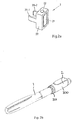
- Fig. 1 is an exploded view of an injection device 1, which may for instance represent Sanofi's Solostar (R) insulin injection pen.
- an injection device 1 which may for instance represent Sanofi's Solostar (R) insulin injection pen.
- the injection device 1 of Fig. 1 is a pre-filled, disposable injection pen that comprises a housing 10 and contains an insulin container 14, to which a needle 15 can be affixed.
- the needle is protected by an inner needle cap 16 and an outer needle cap 17, which in turn can be covered by a cap 18.
- An insulin dose to be ejected from injection device 1 can be selected by turning a dosage knob 12, and the selected dose is then displayed via a dosage window or display 13, for instance in multiples of so-called International Units (IU), wherein one IU is the biological equivalent of about 45.5 micrograms of pure crystalline insulin (1/22 mg).
- An example of a selected dose displayed in dosage window or display 13 may for instance be 30 IUs, as shown in Fig. 1 .
- the selected dose may equally well be displayed differently, for instance by an electronic display.
- dosage window relates to the section of the injection device through or on which the selected dosage is visible.
- a label (not shown) is provided on the housing 10.
- the label includes information about the medicament included within the injection device, including information identifying the medicament.
- the information identifying the medicament may be in the form of text.
- the information identifying the medicament may also be in the form of a shading or pattern.
- the information identifying the medicament may also be in the form of a colour.
- the information identifying the medicament may also be encoded into a barcode, QR code or the like.
- the dosage knob 12 causes a mechanical click sound to provide acoustical feedback to a user.
- the numbers displayed in dosage display 13 are printed on a sleeve that is contained in housing 10 and mechanically interacts with a piston in insulin container 14.
- the insulin dose displayed in display window 13 will be ejected from injection device 1.
- the needle 15 of injection device 1 remains for a certain time in the skin portion after the injection button 11 is pushed, a high percentage of the dose is actually injected into the patient's body. Ejection of the insulin dose also causes a mechanical click sound, which is however different from the sounds produced when using dosage knob 12.
- Injection device 1 may be used for several injection processes until either insulin container 14 is empty or the expiration date of injection device 1 (e.g. 28 days after the first use) is reached.
- injection device 1 before using injection device 1 for the first time, it may be necessary to perform a so-called "prime shot” to remove air from insulin container 14 and needle 15, for instance by selecting two units of insulin and pressing injection button 11 while holding injection device 1 with the needle 15 upwards.
- a so-called "prime shot” to remove air from insulin container 14 and needle 15, for instance by selecting two units of insulin and pressing injection button 11 while holding injection device 1 with the needle 15 upwards.
- the ejected doses substantially correspond to the injected doses, so that, for instance when making a proposal for a dose to be injected next, this dose equals the dose that has to ejected by the injection device. Nevertheless, differences (e.g. losses) between the ejected doses and the injected doses may of course be taken into account.
- the housing 10 of the injection device 1 comprises a front section 101 and a rear section 102.
- the needle 15 is affixed to the front end of the front section 101 and the dosage knob 12 extends from the rear end of the rear section 102.
- the front section 101 has a smaller diameter than the rear section 102 of the injection device housing 10.
- a shoulder 103 is defined between the front section 101 and the rear section 102. The shoulder 103 extends circumferentially around the housing 10.
- the cap 18 extends over the front section 101.
- the cap 18 covers the front section 101 and a rim 18a of the cap 18 locates against the shoulder 103.
- Two cap retaining protrusions 104 are formed on the outer surface of the front section 101 of the housing 10 of the injection device 1.
- the cap retaining protrusions 104 are disposed proximate to, but spaced from, the shoulder 103.
- the protrusions 104 locate over one or more retaining elements (not shown) formed on the inner surface of the cap 18 to retain the cap 18 in position over the front section 101.
- the cap retaining protrusions 104 locate in a corresponding diametrically extending recess (not shown) formed on the inner surface of the cap 18.
- the height of each protrusion 104, that is in a radial direction of the longitudinal axis of the injection device 1, is less than the height of the shoulder 103 between the front and rear sections 101, 102.
- the two protrusions are disposed diametrically opposite each other.
- the number of protrusions is not limited thereto, and the protrusions are dispersed circumferentially around the front section 101.
- the injection device 1 further comprises additional elements.
- a rib 105 protrudes from an outer surface 106 of the injection device 1.
- the rib 105 acts as an alignment element for locating the body in a specific position relative to the outer surface 106 of the injection device 1.
- the rib 105 upstands from the outer surface 106 of the injection device 1 between the dosage window 13 and the dosage knob 12. In this example, the rib 105 extends for the whole of the distance between the display window 13 and the dosage knob 12. In other examples, the rib is shorter.
- the dosage knob 12 is disposed on the rear section 102 of the injection device housing 10.
- the rib 105 is elongate and extends parallel to the longitudinal axis of the injection device 1.
- the height of the rib 105 that is the distance between the outer surface of the rear section 102 and a distal edge 107 (refer to Figure 9 ) of the rib 105 is greater at the end that is adjacent the dosage knob 12 and tapers down to a zero height at the junction with the display window 13.
- Left and right indents 108 are formed in the outer surface 106 of the injection device 1.
- the two indents 108 are formed in the rear section 102.
- Each indent 108 is formed proximate to the rear end of the injection device housing 10.
- the indents are formed generally diametrically opposite to each other on left and right sides of the injection device 1.
- the indents have chamfered sides.
- Fig. 2a is a schematic illustration of an example of a supplementary device 2 outside the scope of the invention to be releasably attached to injection device 1 of Fig. 1 .
- Supplementary device 2 comprises a housing 20 with a mating unit configured to embrace the housing 10 of injection device 1 of Fig. 1 , so that supplementary device 2 sits tightly on housing 10 of injection device 1, but is nevertheless removable from injection device 1, for instance when the injection device 1 is empty and has to be replaced.
- Fig. 2a is highly schematic, and details of the physical arrangement are described below with reference to Figure 2b .
- Supplementary device 2 contains optical and acoustical sensors for gathering information from injection device 1. At least a part of this information, for instance a selected dose (and optionally a unit of this dose), is displayed via display unit 21 of supplementary device 2. The dosage window 13 of injection device 1 is obstructed by supplementary device 2 when attached to injection device 1. Supplementary device 2 further comprises three user input transducers, illustrated schematically as a button 22. These input transducers 22 allow a user to turn on/off supplementary device 2, to trigger actions (for instance to cause establishment of a connection to or a pairing with another device, and/or to trigger transmission of information from supplementary device 2 to another device), or to confirm something.
- Fig. 2b shows a view of the supplementary device 2 with the arrangement of the mating unit and housing shown in greater detail.
- the supplementary device 2 is shown mounted to the injection device 1 in Fig. 2b .
- the housing 20 of the supplementary device 2 has a body 300 and a securing unit 301.
- the body 300 is elongate.
- a passage 302 extends through the body 300 from a front end 304 to a rear end 305.
- the passage 302 is configured to slidably receive the injection device therethrough.
- the passage 302 is a cylindrical bore formed through the body 300.
- the passage 302 is dimensioned to receive a rear section 102 of the injection device therethrough.
- the injection device 1 is cylindrical and the passage 302 has a diameter which is slightly greater than the diameter of the rear section 102 of the injection device 1 so that the injection device 1 is slidable therealong.
- the securing unit 301 is disposed at the front end 304 of the body 300.
- the securing unit 301 comprises a collar 303.
- the collar 303 is rotatably mounted to the body 300.
- the collar 303 extends from the front end 304.
- the collar 303 is movable between an retracted position and a secured position to secure the supplementary device to the injection device, as will become apparent hereinafter.
- the injection device 1 is receivable through the collar 303 when the device is received in the passage 302 in the body 300.
- the collar 303 and channel 307 form part of a locating arrangement or locating unit.
- the locating unit is configured to locate the body in a specific position relative to the outer surface 106 of the injection device 1.
- the locating unit forms part of the mating unit configured to embrace the housing 10 of injection device 1 to maintain the supplementary device in a specific position on the injection device 1.
- the supplementary device 2 further comprises a securing arrangement or unit configured to releasably mount the body to the injection device 1.
- the collar 303 also forms part of the securing unit.
- the securing unit form part of the mating unit.
- the features that contribute to correct location or alignment of the supplementary device 2 on the injection device 1 can be termed a locating arrangement or locating unit.
- the features that contribute to securing of the supplementary device 2 to the injection device 1 can be termed a securing unit or securing arrangement.
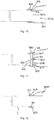
- Figs. 3A and 3b show possible distributions of functions among devices when using a supplementary device (such as the supplementary devices of Fig. 2a and 2b ) together with an injection device.
- a supplementary device such as the supplementary devices of Fig. 2a and 2b
- the supplementary device 41 determines information from injection device 40, and provides this information (e.g. type and/or dose of the medicament to be injected) to a blood glucose monitoring system 42 (e.g. via a wired or wireless connection).
- Blood glucose monitoring system 42 (which may for instance be embodied as a desktop computer, personal digital assistant, mobile phone, tablet computer, notebook, netbook or ultrabook) keeps a record of the injections a patient has received so far (based on the ejected doses, for instance by assuming that the ejected doses and the injected doses are the same, or by determining the injected doses based on the ejected doses, for instance be assuming that a pre-defined percentage of the ejected dose is not completely received by the patient). Blood glucose monitoring system 42 may for instance propose a type and/or dose of insulin for the next injection for this patient.
- blood glucose meter 43 may be embodied as a separate device that is configured to receive a small blood probe (for instance on a carrier material) of a patient and to determine the blood glucose level of the patient based on this blood probe.
- Blood glucose meter 43 may however also be a device that is at least temporarily implanted into the patient, for instance in the patient's eye or beneath the skin.
- Fig. 3b is a modified constellation 4' where the blood glucose meter 43 of Fig. 3a has been included into blood glucose monitoring system 42 of Fig. 3a , thus yielding the modified blood glucose monitoring system 42' of Fig. 3b .
- the functionalities of injection device 40 and supplementary device 41 of Fig. 3a are not affected by this modification.
- the functionality of blood glucose monitoring system 42 and blood glucose meter 43 combined into blood glucose monitoring system 42' are basically unchanged, apart from the fact that both are now comprised in the same device, so that external wired or wireless communication between these devices is no longer necessary. However, communication between blood glucose monitoring system 42 and blood glucose meter 43 takes place within system 42'.
- Fig. 4 shows a schematic view of the supplementary device 2 of Fig. 2a in a state where it is attached to injection device 1 of Fig. 1 .
- a plurality of components are comprised. These are controlled by a processor 24, which may for instance be a microprocessor, a Digital Signal Processor (DSP), Application Specific Integrated Circuit (ASIC), Field Programmable Gate Array (FPGA) or the like.
- Processor 24 executes program code (e.g. software or firmware) stored in a program memory 240, and uses a main memory 241, for instance to store intermediate results.
- Main memory 241 may also be used to store a logbook on performed ejections/injections.
- Program memory 240 may for instance be a Read-Only Memory (ROM), and main memory may for instance be a Random Access Memory (RAM).
- processor 24 interacts with a first button 22, via which supplementary device 2 may for instance be turned on and off.
- a second button 33 is a communications button. The second button may be used to trigger establishment of a connection to another device, or to trigger a transmission of information to another device.
- a third button 34 is a confirm or OK button. The third button 34 can be used to acknowledge information presented to a user of supplementary device 2.
- the buttons 22, 33, 34 may be any suitable form of user input transducers, for instance mechanical switches, capacitive sensors or other touch sensors.
- Display unit 21 is used to display information to a user of supplementary device 2, for instance on present settings of injection device 1, or on a next injection to be given.
- Display unit 21 may also be embodied as a touch-screen display, for instance to receive user input.
- Processor 24 also controls an optical sensor 25, embodied as an Optical Character Recognition (OCR) reader, that is capable of capturing images of the dosage window 13, in which a currently selected dose is displayed (by way of numbers printed on the sleeve 19 contained in injection device 1, which numbers are visible through the dosage window 13).
- OCR reader 25 is further capable of recognizing characters (e.g. numbers) from the captured image and to provide this information to processor 24.
- unit 25 in supplementary device 2 may only be an optical sensor, e.g. a camera, for capturing images and providing information on the captured images to processor 24. Then processor 24 is responsible for performing OCR on the captured images.
- Processor 24 also controls light-sources such as light emitting diodes (LEDs) 29 to illuminate the dosage window 13, in which a currently selected dose is displayed.
- LEDs light emitting diodes
- a diffuser may be used in front of the light-sources, for instance a diffuser made from a piece of acrylic glass.
- the optical sensor may comprise a lens (e.g. an aspheric lens) leading to a magnification (e.g. a magnification of more than 3:1).
- Processor 24 further controls a photometer 26, that is configured to determine an optical property of the housing 10 of injection device 1, for example a colour or a shading.
- the optical property may only be present in a specific portion of housing 10, for example a colour or colour coding of sleeve 19 or of an insulin container comprised within injection device 1, which colour or colour coding may for instance be visible through a further window in housing 10 (and/or in sleeve 19).
- Information on this colour is then provided to processor 24, which may then determine the type of injection device 1 or the type of insulin contained in injection device 1 (e.g. SoloStar Lantus with purple colour and SoloStar Apidra with blue colour).
- a camera unit may be used instead of photometer 26, and an image of the housing, sleeve or insulin container may then be provided to processor 24 to determine the colour of the housing, sleeve or insulin container by way of image processing.
- one or more light sources may be provided to improve reading of photometer 26.
- the light source may provide light of a certain wavelength or spectrum to improve colour detection by photometer 26.
- the light source may be arranged in such a way that unwanted reflections, for example by dosage window 13, are avoided or reduced.
- a camera unit instead of or in addition to photometer 26, a camera unit may be deployed to detect a code (for instance a bar code, which may for instance be a one- or two-dimensional bar code) related to the injection device and/or the medicament contained therein.
- This code may for instance be located on the housing 10 or on a medicament container contained in injection device 1, to name but a few examples.
- This code may for instance indicate a type of the injection device and/or the medicament, and/or further properties (for instance
- Processor 24 further controls (and/or receives signals from) an acoustic sensor 27, which is configured to sense sounds produced by injection device 1. Such sounds may for instance occur when a dose is dialled by turning dosage knob 12 and/or when a dose is ejected/injected by pressing injection button 11, and/or when a prime shot is performed. These actions are mechanically similar but nevertheless sound differently (this may also be the case for electronic sounds that indicate these actions). Either the acoustic sensor 27 and/or processor 24 may be configured to differentiate these different sounds, for instance to be able to safely recognize that an injection has taken place (rather than a prime shot only).
- Processor 24 further controls an acoustical signal generator 23, which is configured to produce acoustical signals that may for instance be related to the operating status of injection device 1, for instance as feedback to the user.
- an acoustical signal may be launched by acoustical signal generator 23 as a reminder for the next dose to be injected or as a warning signal, for instance in case of misuse.
- Acoustical signal generator may for instance be embodied as a buzzer or loudspeaker.
- a haptic signal generator (not shown) may be used to provide haptic feedback, for instance by way of vibration.
- Processor 24 controls a wireless unit 28, which is configured to transmit and/or receive information to/from another device in a wireless fashion. Such transmission may for instance be based on radio transmission or optical transmission.
- the wireless unit 28 is a Bluetooth transceiver.
- wireless unit 28 may be substituted or complemented by a wired unit configured to transmit and/or receive information to/from another device in a wire-bound fashion, for instance via a cable or fibre connection.
- the units of the data (values) transferred may be explicitly or implicitly defined. For instance, in case of an insulin dose, always International Units (IU) may be used, or otherwise, the used unit may be transferred explicitly, for instance in coded form.
- IU International Units
- Processor 24 receives an input from a pen detection switch 30, which is operable to detect whether the pen 1 is present, i.e. to detect whether the supplementary device 2 is coupled to the injection device 1.
- a battery 32 powers the processor 24 and other components by way of a power supply 31.
- the supplementary device 2 of Fig. 4 is thus capable of determining information related to a condition and/or use of injection device 1. This information is displayed on the display 21 for use by the user of the device. The information may be either processed by supplementary device 2 itself, or may at least partially be provided to another device (e.g. a blood glucose monitoring system).
- a blood glucose monitoring system e.g. a blood glucose monitoring system
- Figs. 5a-5c are flowcharts of embodiments of methods according to the present invention. These methods may for instance be performed by processor 24 of supplementary device 2 (see Figs. 2b and 4 ), but also by a processor of supplementary device 3 of Fig. 2b , and may for instance be stored in program memory 240 of supplementary device 2, which may for instance take the shape of tangible storage medium 60 of Fig. 6 .
- Fig. 5a shows method steps that are performed in scenarios as shown in Figs. 3a and 3b , where information read by supplementary device 41 from injection device 40 is provided to blood glucose monitoring system 42 or 42' without receiving information back from blood glucose monitoring system 42 or 42'.
- the flowchart 500 starts for instance when the supplementary device is turned on or is otherwise activated.
- a type of medicament for example insulin
- a type of medicament for example insulin
- a code printed on injection device or a component thereof as already described above. Detection of the type of medicament may not be necessary if a patient always takes the same type of medicament and only uses an injection device with this single type of medicament. Furthermore, determination of the type of medicament may be ensured otherwise (e.g. by the key-recess pair shown in Fig. 4 that the supplementary device is only useable with one specific injection device, which may then only provide this single type of medicament).
- a currently selected dose is determined, for instance by OCR of information shown on a dosage window of injection device as described above. This information is then displayed to a user of the injection device in a step 503.
- a prime shot may be differentiated from an actual injection (into a creature) either based on respectively different sounds produced by the injection device and/or based on the ejected dose (e.g. a small dose, for instance less than a pre-defined amount of units, e.g. 4 or 3 units, may be considered to belong to a prime shot, whereas larger doses are considered to belong to an actual injection).
- a small dose for instance less than a pre-defined amount of units, e.g. 4 or 3 units, may be considered to belong to a prime shot, whereas larger doses are considered to belong to an actual injection.
- the determined data i.e. the selected dose and - if applicable - the type of medicament (e.g. insulin)
- the main memory 241 from where it may later be transmitted to another device, for instance a blood glucose monitoring system.
- a differentiation has been made concerning the nature of the ejection for instance if the ejection was performed as a prime shot or as an actual injection, this information may also be stored in the main memory 241, and possibly later transmitted.
- the dose is displayed on the display 21. Also displayed is a time since the last injection which, immediately after injection, is 0 or 1 minute. The time since last dose may be displayed intermittently. For instance, it may be displayed alternately with the name or other identification of the medicament that was injected, e.g. Apidra or Lantus.
- steps 502 and 503 are repeated.
- Fig. 5c shows in more detail exemplary method steps that are performed when the selected dose is determined based on the use of optical sensors only. For instance, these steps may be performed in step 502 of Fig. 5a .
- a sub-image is captured by an optical sensor such as optical sensor 25 of supplementary device 2.
- the captured sub-image is for instance an image of at least a part of the dosage window 13 of injection device 1, in which a currently selected dose is displayed (e.g. by way of numbers and/or a scale printed on the sleeve 19 of injection device 1, which is visible through the dosage window 13).
- the captured sub-image may have a low resolution and/or only show a part of the part of sleeve 19 which is visible through dosage window 13.
- the captured sub- image either shows the numbers or the scale printed on the part of sleeve 19 of injection device 1 which is visible through dosage window 13.
- a step 902 it is determined whether or not there is a change in the captured sub-image.
- the currently captured sub-image may be compared to the previously captured sub-image(s) in order to determine whether or not there is a change.
- the comparison to previously captured sub-images may be limited to the sub-image of the previously captured sub-images that was captured immediately before the current sub-image was captured and/or to the sub-images of the previously captured sub-images that were captured within a specified period of time (e.g. 0.1 seconds) before the current sub-image was captured.
- the comparison may be based on image analysis techniques such as pattern recognition performed on the currently captured sub-image and on the previously captured sub-image.
- Steps 901 and 902 may correspond to a detection of a change in the captured image.
- step 901 is repeated. Otherwise in a step 903, an image is captured by an optical sensor such as optical sensor 25 of supplementary device 2.
- the captured image is for instance an image of the dosage window 13 of injection device 1, in which a currently selected dose is displayed (e.g. by way of numbers and/or a scale printed on the sleeve 19 of injection device 1, which is visible through the dosage window 13).
- the captured image may have a resolution being higher than the resolution of the captured sub-image.
- the captured image at least shows the numbers printed on the sleeve 19 of injection device 1 which are visible through the dosage window 13.
- step 904 optical character recognition (OCR) is performed on the image captured in step 903 in order to recognize the numbers printed on the sleeve 19 of injection device 1 and visible through the dosage window 13, because these numbers correspond to the (currently) selected dose.
- OCR optical character recognition
- the selected dose is determined, for instance by setting a value representing the selected dose to the recognized numbers.
- a step 905 it is determined whether or not there is a change in the determined selected dose and, optionally, whether or not the determined selected dose does not equal zero.
- the currently determined selected dose may be compared to the previously determined selected dose(s) in order to determine whether or not there is a change.
- the comparison to previously determined selected dose(s) may be limited to the previously determined selected dose(s) that were determined within a specified period of time (e.g. 3 seconds) before the current selected dose was determined. If there is no change in the determined selected dose and, optionally, the determined selected dose does not equal zero, the currently determined selected dose is returned/forwarded for further processing (e.g. to processor 24).
- the selected dose is determined if the last turn of the dosage knob 12 is more than 3 seconds ago. If the dosage knob 12 is turned within or after these 3 seconds and the new position remains unchanged for more than 3 seconds, this value is taken as the determined selected dose.
- Fig. 5c shows in more detail method steps that are performed when the selected dose is determined based on the use of acoustical and optical sensors. For instance, these steps may be performed in step 502 of Figs. 5a .
- a sound is captured by an acoustical sensor such as acoustical sensor 27 of supplementary device 2.
- a step 1002 it is determined whether or not the captured sound is a click sound.
- the captured sound may for instance be a click sound that occurs when a dose is dialled by turning dosage knob 12 of injection device 1 and/or when a dose is ejected/injected by pressing injection button 11, and/or when a prime shot is performed. If the captured sound is not a click sound, step 1001 is repeated. Otherwise in a step 1003, an image is captured by an optical sensor such as optical sensor 25 of supplementary device 2. Step 1003 corresponds to step 903 of flowchart 900.
- Step 1004 an OCR is performed on the image captured in step 1003.
- Step 1004 corresponds to step 904 of flowchart 900.
- Step 1005 it is determined whether or not there is a change in the determined selected dose and, optionally, whether or not the determined selected dose does not equal zero. Step 1005 corresponds to step 905 of flowchart 900.
- Fig. 6 is a schematic illustration of a tangible storage medium 60 (a computer program product) that comprises a computer program 61 with program code 62 according to aspects of the present invention.
- This program code may for instance be executed by processors contained in the supplementary device, for instance processor 24 of supplementary device 2 of Figs. 2a and 4 .
- storage medium 60 may represent program memory 240 of supplementary device 2 of Fig. 4 .
- Storage medium 60 may be a fixed memory, or a removable memory, such as for instance a memory stick or card.
- Fig. 7 is an information sequence chart 7 that illustrates the flow of information between various devices (e.g. the injection device 1 and the supplementary device 2 of Fig. 4 in a scenario as depicted in Figs. 3a or 3b ) according to an embodiment of the present invention.
- a condition and/or use of injection device 70 affects an appearance of its dosage window, sounds generated by injection device 70 and a colour of the housing.
- This information is transformed by sensors 710 of supplementary device 71 into an OCR signal, an acoustic sensor signal and a photometer signal, respectively, which are in turn transformed into information on the dialled dose, on an injection/dialling operation and on the type of insulin by a processor 711 of supplementary device 71, respectively.
- This information is then provided by supplementary device 70 to a blood glucose monitoring system 73. Some or all of this information is displayed to a user 72 via the display 21.
- embodiments of the present invention allow connection of a standard injection device, in particular an insulin device, with a blood glucose monitoring system in a useful and productive way.
- Embodiments of the present invention introduce a supplementary device to allow for this connection, assuming the blood glucose monitoring system has wireless or other communication capabilities.
- the benefits from the connection between the blood glucose monitoring and an insulin injection device are inter alia the reduction of mistakes by the user of the injection device and a reduction of handling steps - no more manual transfer of the injected insulin unit to a blood glucose monitoring is required, in particular to a blood glucose monitoring system with functionality of providing guidance for the next dose based on the last dose injected and latest blood glucose values.
- the user attaches the supplementary device to the pen by use of the mating unit, as will be described in detail hereinafter.
- the supplementary device reads out the injected dose. It may also transfer it to a blood glucose monitoring system with insulin titration capabilities. For patients taking multiple insulins, the supplementary device recognizes the device structure to the insulin type and may also transmit this piece of information to the blood glucose monitoring system.
- the mating unit for releasably mounting the supplementary device to the injection device in a specific position relative to an outer surface of the injection device will now be described in detail.
- the correct alignment of the supplementary device 2 on the injection device 1 ensures that the OCR reader 25 is correctly aligned with the dosage window 13. Correct alignment and location allows correct operation and reliable readings. Ensuring that there can be correct alignment between the supplementary device 2 and the injection device 1 in use allows a simpler design for the OCR reader 25, in particular because it does not need to be designed to be able to accommodate different alignments between the devices 1, 2.
- the mating unit comprises the securing unit 301 and the locating unit.
- the locating unit is configured to locate the body in a specific position relative to the outer surface 106 of the injection device 1.
- the securing unit 301 is configured to releasably secure the body to the injection device so that the body is retained in the specific position relative to the outer surface 106 of the injection device 1.
- the supplementary device 2 is shown received on the injection device 1.
- the injection device 1 is received through the passage 302 formed in the body 300.
- the injection device 1 protrudes from each end of the body 300, with the injection device 1 also protruding through the securing unit 301.
- the securing unit 301 comprises the collar 303 and two securing arms; an upper arm 307 and a lower arm 308.
- the arms 307, 308 act as securing members.
- the arms 307, 308 extend around an opening 309 to the passage 302 at the front end 304 of the body 300. Therefore, each arm 307, 308 has an arcuate shape.
- the arms 307, 308 form a circumferentially extending arrangement around the opening 309. Two slots 310 separate the arms 307, 308 from each other. Therefore, side edges 311 of the arms 307, 308 are spaced from each other to allow the arms to deflect relative to each other.
- Each arm 307, 308 protrude from a front face 314 of the body 300.
- the front face 314 is formed at the front end 304 of the body 300.
- the arms protrude substantially parallel to the longitudinal axis of the injection device receiving passage 302.
- Each arm has an inner surface 312.
- the inner surface 312 of each arm acts as a clamping surface.
- the clamping surface is configured to locate against and mate with the injection device 1.
- the clamping surface 312 of each arm 307, 308 extends co-planar with the inner surface of the injection device receiving passage 302.
- Each arm 307, 308 has an outer surface 313.
- the outer surface 313 of each arm is arcuate so that the arms together define a cylindrical shape.
- a circumferentially extending ridge 315 is formed at a free edge 316 of each arm 307, 308.
- the ridge 315 upstands from the outer surface 313 of each arm.
- the ridge 315 has a triangular form in cross-section; that is front and rear faces of the ridge 315 are inclined towards each other.
- the ridge 315 on each arm 307, 308 extends along the length of the free edge 316 of each arm 307, 308, it will be understood that each ridge may extend along along part of the free edge 316, or be formed in a number of separate portions.
- the ridge 315 extends parallel to the front face 314 of the body 300.
- Each arm 307, 308 is integrally formed with the body 300. Alternatively, the arms are fixedly mounted to the body 300. Each arm 307 is formed from a resilient material so that it is able to flex in a radial direction, as will be explained hereinafter.
- An elongate tab 317 is formed on the outer surface 313 of each arm 307, 308. Each elongate tab 317 extends in a circumferential direction along the outer surface 313 of the respective arm.
- the tab 317 acts as a collar end stop to limit movement of the collar 303 relative to the body 300, as will become apparent hereinafter.
- the tab 317 is spaced from the front face 314 of the body 300.
- the tab 317 is also spaced from the ridge 315.
- the collar 303 has a toroidal shape.
- the collar 303 has an outer face 320 and an inner face 321.
- the outer face 320 has a number of projections 322 formed equidistant around the outer face 320 to enable a user to easily grip the collar 303. Therefore, a user is able to apply a rotational force to rotate the collar 303 relative to the body 300.
- the inner face 321 of the collar 303 forms a guide section 323 and a biasing section 324.
- the biasing section 324 of the collar 303 acts on the arms 307, 308 to urge the arms to deflect in a radial direction.
- the biasing section 324 has a tapered thread formed thereon which converges towards a front end of the collar, that is the end of the collar disposed distal to the body 300 when the collar 303 is mounted with the body 300.
- the tapered thread of the biasing section 324 threadingly engages with the ridge 315 on each arm 307, 308.
- the biasing section 324 is formed at a front end of the collar 303.
- the guide section 324 extends from the biasing section 324.
- a circumferentially extending lip 325 is formed on the inner face 321 of the collar 303.
- the lip 325 extends inwardly around the rear edge of the inner face 321.
- the guide section 324 extends between the lip 325 and the biasing section 324.
- the collar 303 is rotatably mounted to the arms 307, 308.
- the collar 303 extends over the arms 307, 308. Therefore, the arms are generally hidden from view by the collar 303 when the collar is mounted to the arms.
- a rear part of the arms 307, 308 proximate to the front face 314 of the body may be visible to a user when the collar is in its retracted position.
- a locating channel 330 is formed in the body 300 (refer to Figure 9 ).
- the locating channel 330 is formed in the inner surface of the passage 302 formed in the body 300.
- the channel 330 extends from a rear face 332 of the body 300 at the rear end 305 of the body 300. Therefore, the channel 330 forms an opening in the rear face 332 of the body 300 which extends from the rear opening to the passage 302.
- the locating channel 330 is dimensioned so as to correspond closely to the shape and size of the locating rib 330 that is present on the injection pen 1.
- the locating channel 330 has a size and shape that corresponds closely to the size and shape of the locating rib 105.
- the locating channel 330 is slightly larger than the locating rib so as to ensure that the locating rib can be located within the locating channel 330.
- the corresponding sizes ensure that the two features mate together. This assists in ensuring correct positioning of the supplementary device 2 on the injection device 1.
- the locating channel 330 is open at the rear end of the body 300 and so it will be understood that the rib 105 is able to be slid into the locating channel 330 in a direction of the longitudinal axis of the passage 302.
- the locating channel 330 forms part of or the locating unit.
- the locating unit is configured to locate the body in a specific position relative to the outer surface 106 of the injection device 1.
- the locating channel 330 forms part of the mating unit configured to embrace the housing 10 of injection device 1 to maintain the supplementary device in a specific position on the injection device 1.
- the collar 303 When the securing unit 301 is assembled, the collar 303 is mounted to the arms 307, 308 and extends thereover.
- the tapered thread of the collar biasing section 324 engages with the ridge 315 on the outer surface 313 of the arms 307, 308.
- the lip 325 is disposed between the circumferentially extending tab 317 of each arm and the front face 314 of the body 300. Therefore, the collar 303 is able to rotate about the arms 307, 308, thus being rotatable relative to the body 300.
- the securing unit 301 is initially disposed in a retracted position, as shown in Figures 10 and 11 .
- the collar 303 is spaced from the front face of the body.
- the ridge 315 at the free edge 316 of each arm is disposed at the diverged end of the tapered thread of the biasing section 324.
- the arms 307, 308 extend parallel to each other or depend away from each other.
- the lip 325 of the collar 303 is located against the circumferentially extending tab 317 on the outer surface 313 of each arm.
- the tab 317 acts as an end stop to limit the movement of the collar 303 along the arms 307, 308. Therefore, rotation of the collar 303 is restricted when the lip 325 abuts against the tab 317 on each arm 307, 308 to prevent the ridge from disengaging from the biasing section and/or the collar from becoming detached from the arms.
- the supplementary device 2 is initially located with respect to the injection device.
- the cap 18 is removed from the injection device 1 and the supplementary device 2 is aligned with the front end of the injection device 1.
- the body 300 is orientated so that the longitudinal axis of the injection device receiving passage 302 is co-axial with the longitudinal axis of the injection device 1.
- the supplementary device 2 is received over the injection device 1 so that the injection device is inserted into and received through the passage 302 in the body 300. Therefore, the body 300 acts as a sheath.
- the body 300 is received over the injection device 1 rear end 305 first.
- the front section 101 of the injection device 1 is able to easily pass through the passage 302 due to the front section 101 having a smaller diameter than the rear section 102, and therefore the passage 302.
- the body 300 subsequently slides over the rear section 102.
- the rear section 102 has a diameter which is slightly smaller than the diameter of the passage 302 so that the injection device 1 is slidable through the passage 302.
- the locating rib 105 is slid to the rear end 305 of the body 300.
- a user rotates the body 300 about the longitudinal axis of the injection device so that the locating channel 330 is aligned with the rib 105.
- the channel 330 is then able to slide over the rib 105 to correctly orientate the body with respect to the injection device 1.
- the channel 330 is dimensioned so as to correspond closely to the shape and size of the locating rib 105, and so the supplementary device continues to slide over the injection device 1 until the rib 105 is fully received in the channel 330. Therefore, the channel 330 acts as an alignment element for locating the body 300 in a specific position relative to the outer surface 106 of the injection device 1 when the rib 105 is received in the channel 330.
- the rib 105 will not be received in the channel 330 formed in the body 300.
- the supplementary device 2 is prevented from being located fully over the injection device 1 by the rib 105 resting against the rear face 332 of the body 300.
- a user would know that the supplementary device 2 had not mated correctly with the injection pen 1 because the rib 105 would be clearly visible. They would also notice that the rear end of the supplementary device was spaced from the rear end of the injection device 1.
- a user can simply rotate the supplementary device 2 relative to the injection device 1 about the longitudinal axis of the injection device 1. As the supplementary device 2 and the injection device 1 move relative to one another, the locating rib and the channel 330 become aligned with each other. Similarly, if the supplementary device 2 is not correctly aligned on the injection device 1 in a longitudinal direction, the rib 105 will not be fully located in the recess 330.
- the supplementary device 2 is correctly located within the injection device 1.
- the outermost surface of the display window 13 is aligned with a lowermost surface of the upper part of the supplementary device 2.
- the securing unit 301 is then operated to secure the supplementary device 2 on the injection device 1.
- the injection device 1 is received through the passage, the injection device is received through the securing unit 301.
- the injection device 1 is received between the arms 307, 308 such that, when the body 300 is located in the desired specific position, part of the rear section 102 of the injection device is disposed between the arms 307, 308.
- the collar is rotated in a clockwise direction when looking at the injection device from a front end.
- the thread of the collar biasing section 324 which is in engagement with the ridge 315 on the arms 307, 308 urges the collar to move in a longitudinal direction towards the body 300.
- the thread of the collar biasing section 324 is tapered and so the collar biasing section 324 acts on the free end of each arm to urge the arms to deflect inwardly in a radial direction.
- the arms 307, 308 are therefore urged to deflect inwardly as the tapered thread, acting on the free edge 316 of each arm, converges.
- the arms 307, 308 continue to be urged towards each other by the biasing section 324. Therefore, the arms 307, 308 are biased towards the outer surface 106 of the injection device 1.
- the clamping surface 312 of each arm 307, 308 locates against the outer surface 106 of the injection device 1 and are urged thereagainst. Therefore, as the arms 307, 308 are biased towards each other the injection device 1 is clamped between the arms 307, 308.
- the supplementary device 2 is then securely held in position on the injection device 1 and cannot move relative to the injection device.
- the securing unit 301 is then in a secured position as shown in Figure 12 .
- the thread of the collar biasing section 324 has a fine thread, that is the thread has a small pitch, the collar 303 is not urged to rotate in the opposing direction when the rotational force applied by the user is released. Therefore, the reaction force applied due to the resilience of the arms 307, 308 does not cause the securing unit to move from a secured position to a retracted position.
- Rotation of the collar 303 is restricted by the lip 325 of the collar 303 locating against the front face 314 of the body 300. This limits the deflection of the arms 307, 308 by the collar, and so prevents damage to the arms and/or the injection device 1.
- the above arrangement prevents movement of the injection device 1 relative to the supplementary device 2.
- a user exerts a rotational force on the collar 303 to rotate the collar in the opposite direction.
- the collar 303 then rotates relative to the body 300 and moves in a longitudinal direction away from the body 300.
- the ridge 315 at the free edge 316 of each arm 307, 308 moves to the diverged section of the biasing section 324 of the collar 303, the resilience of the arms 307, 308 causes the arms to deflect outwardly in a radial direction away from each other.
- the arms 307, 308 therefore deflect away from the outer surface of the injection device 1.
- each arm is therefore spaced from the outer surface of the injection device 1 such that the injection device is not clamped therebetween.
- the injection device 1 may then be slid from the supplementary device 2 without being constrained by the securing unit 301.
- the supplementary unit includes the body 400 and a mating unit.
- the mating unit comprises the securing unit 401 and the locating unit.
- the locating unit is configured to locate the body in a specific position relative to the outer surface 106 of the injection device 1.
- the securing unit 301 is configured to releasably secure the body to the injection device so that the body is retained in the specific position relative to the outer surface 106 of the injection device 1.
- the supplementary device 2 is shown dismounted from the injection device 1.
- the supplementary device 2 of this embodiment has a longitudinal length which is longer than that of the supplementary device described above and shown in Figures 8 to 12 .
- the securing unit 401 is arranged to clamp against the front section 101 of the injection device 1. This enables the shoulder 103 between the front and rear sections 101, 102 to be used to aid location of the supplementary device in a specific position on the injection device 1.
- a passage 402 extends through the body 400 from a front end 404 to a rear end 405.
- the passage 402 is configured to slidably receive the injection device therethrough.
- the passage 402 is a cylindrical bore formed through the body 400.
- a step is formed in the passage 402 formed in the body 400. The step extends circumferentially around the inner surface of the passage 402. The step defines a rear part of the passage 402.
- the rear part of the passage 402 extends in the rear end 405 of the body 400.
- the rear part of the passage 402 has a diameter which is slightly greater than the diameter of the rear section 102 of the injection device 1 so that the front and rear sections 101, 102 of the injection device 1 is slidable along the rear part.
- the step also defines a front part of the passage 402.
- the rear part of the passage 402 extends from the rear part of the passage 402 and extends in the front end 404 of the body 400.
- the front part of the passage 402 has a diameter which is slightly greater than the diameter of the front section 101 of the injection device 1. Therefore, the front section 101 is slidable through and along the front part of the passage 402. However, the rear section 102 of the injection device is prevented from sliding along the front part of the passage 402 due to the front part of the passage 402 having a diameter which is slightly less than the diameter of the rear section 102 of the injection device 1.
- the front section of the passage 402 may be a circumferentially extending flange.
- the step is formed in the passage 402 it will be understood that in an alternative embodiment the step is formed between the passage and the securing unit. That is, the diameter of the aperture defined through the securing unit is smaller than the diameter of the passage. In such an arrangement, the diameter of the aperture defined through the securing unit is slightly greater than the diameter of the front section of the injection device, but less than the diameter of the rear section of the injection device.
- the step may be formed in the securing unit. In this arrangement the clamping surface of each arm may have a step formed in it.
- the arrangement of the securing unit is generally the same as the securing unit described in the above embodiment, and so a detailed description will be omitted herein. That is, the arm and collar arrangement of the securing unit is generally the same.
- the arms act as securing members and extend from the body. Slots separate the arms from each other. However, in this embodiment the slots separating the arms from each other are configured to receive the cap retaining protrusions 104 formed on the outer surface of the front section 101 of the housing 10 of the injection device 1.
- the slots act as guide slots to aid the location of the supplementary device 2 on the injection device 1.
- the cap retaining protrusions 104 upstanding from the front section 101 of the injection device 1 are received in the slots between the arms. Therefore, the slots form part of or act as the locating unit and aid location of the body in a specific position relative to an outer surface of the injection device.
- the cap retaining protrusions 104 are disposed proximate to, but spaced from, the shoulder 103 of the injection device.
- the protrusions 104 locate over one or more retaining elements (not shown) formed on the inner surface of the cap 18 to retain the cap 18 in position over the front section 101.
- the supplementary device extends partially along the front section of the supplementary device. Therefore, it is not possible for the cap 18 to be retained by the retaining elements.
- the supplementary device further comprises two auxiliary cap retaining members 407 extending from a front side 406 of the securing unit 401.
- the auxiliary cap retaining members 407 each comprise a finger 408 and a cap retaining protrusion 409.
- the fingers 408 of the cap retaining members 407 are spaced from each other to receive the front section of the injection device therethrough. That is, when the fingers 408 are spaced diametrically opposite each other, the distance between the inner surface of the fingers 408 corresponds to the diameter of the front section 101.
- the fingers 408 extend from the front side 406 of the securing unit 401. In the present embodiment the fingers extend from the free edge of each securing arm of the securing unit, and extend past the front edge of the collar. Alternatively, the fingers 408 extend from the front edge of the collar.
- the thickness of the fingers 408 of the cap retaining members 407 is less than the height of the retaining elements between the injection device outer surface and the distal edge.
- the cap retaining elements 409 have a height corresponding to the height of the retaining protrusions. That is, the distance between the inner surface of the fingers 408 and the free edge of the cap retaining elements 409 is the same as the height of the retaining protrusions between the injection device outer surface and the distal free edge of the cap retaining protrusions 104. Therefore, the cap 18 will engage with the cap retaining elements 409 when the fingers are disposed against the outer surface of the front section 101 of the injection device 1.
- the distance between the cap retaining elements 409 and the front edge 406 of the securing unit 401 is equal to the distance between the cap retaining protrusions on the injection device and the shoulder of the injection device 1. Therefore, the cap rim 18a will locate against the front edge 406 of the securing unit 401 when the cap is engaged with the cap retaining elements 409.
- the supplementary device 2 is initially located with respect to the injection device.
- the cap 18 is removed from the injection device 1 and the supplementary device 2 is aligned with the front end of the injection device 1.
- the body 400 is orientated so that the longitudinal axis of the injection device receiving passage 402 is co-axial with the longitudinal axis of the injection device 1.
- the supplementary device 2 is received over the injection device 1 so that the injection device is inserted into and received through the passage 402 in the body 400. Therefore, the body 400 acts as a sheath.
- the body 400 is received over the injection device 1, with the rear end 405 being received over first.
- the front section 101 of the injection device 1 is able to pass through the front part of the passage 402 due to the front section 101 having a smaller diameter front part of passage 402.
- the rear section 102 of the injection device 1 is subsequently slid into the passage 102.
- the rear section 102 is able to slide into the rear part of the passage 402, but is prevented from sliding into the front part due to the rear section 102 of the injection device 1 having a diameter which is greater than the diameter of the front part of the passage 402. Therefore, the shoulder of the injection device abuts against the step. Therefore, the step mates with the shoulder and acts as a locating element.
- the locating rib 105 is received in the locating channel formed in the body.
- the supplementary device is then correctly orientated with respect to the injection device 1.
- the step is formed along the supplementary device so that the body 400 is located in a specific position relative to the outer surface 106 of the injection device 1 in a longitudinal direction when the shoulder is received against the step.
- the rib 105 will not be received in the channel formed in the body. A user would then know that the supplementary device 2 had not mated correctly with the injection pen 1 because the rib 105 would be clearly visible.
- the cap retaining elements are then received against and extend along the outer surface of the front section 101 of the injection device 1. A user is then able to locate the cap 18 over the front section 101 and engage the cap with the cap retaining elements 407.
- an opening 440 is formed in the body 400 of the supplementary device 2 to allow a user to view information on the injection device 1 that would otherwise be hidden by the body 400.
- a secondary opening 441 is formed on the opposing side of the body 400. The openings allow the label (not shown) provided on the housing 10 to be visible to a user. Therefore a user is able to view the label to view information about the medicament included within the injection device, including information identifying the medicament without removing the supplementary device 2.
- tapered thread is formed on the collar and engages with a part-circumferentially extending ridge on each arm
- the tapered thread may be formed on the outer surface of each arm and the corresponding ridge formed on the inner face of the collar.
- a tapered thread may be formed on each of the collar and each arm.
- the collar and each arm are threadingly engaged by a parallel thread arrangement, and part of the inner face of the collar has a conical biasing face which acts on each arm as the collar is rotated about the body.
- a conical or diverging face may be formed on the outer surface of each arm against which the inner face of the collar acts.
- the securing unit 301 may include a different number of engaging arms.
- the securing unit may have three or four engaging arms.
- the securing unit and locating unit are separate in the above described embodiments, it will be appreciated that the two units may be integral with each other.
- the rear end of the arms may have a step formed in them.
- the rib 105 and rib receiving channel aid orientation and location of the supplementary device 2 on the injection device 1 in the above described embodiments, it will be appreciated that in an alternative arrangement the rib 105 and rib receiving recess 318 are omitted and the correct alignment between the supplementary device 2 and the injection device 1 is provided by the step locating against the shoulder.
- the user inter alia has the following advantages:
- the user can use the most convenient disposable insulin injector.
- the supplementary device is attachable and detachable (reusable).
- the locating unit ensures that the optical sensor is aligned with the dosage window. Therefore, a user does not have to manually orientate the supplementary device.
- the securing unit ensures that the supplementary device is securely mounted to the injection device 1. Therefore, the supplementary device does not inadvertently detach from the injection device.
- the releasable securing arrangement allows the securing unit to be easily disengaged from the injection device. This allows the supplementary device to be drawn away from the injection device without undue effort from a user.
- drug or “medicament”, as used herein, means a pharmaceutical formulation containing at least one pharmaceutically active compound, wherein in one embodiment the pharmaceutically active compound has a molecular weight up to 1500 Da and/or is a peptide, a proteine, a polysaccharide, a vaccine, a DNA, a RNA, an enzyme, an antibody or a fragment thereof, a hormone or an oligonucleotide, or a mixture of the above-mentioned pharmaceutically active compound, wherein in a further embodiment the pharmaceutically active compound is useful for the treatment and/or prophylaxis of diabetes mellitus or complications associated with diabetes mellitus such as diabetic retinopathy, thromboembolism disorders such as deep vein or pulmonary thromboembolism, acute coronary syndrome (ACS), angina, myocardial infarction, cancer, macular degeneration, inflammation
- ACS acute coronary syndrome
- Insulin analogues are for example Gly(A21), Arg(B31), Arg(B32) human insulin; Lys(B3), Glu(B29) human insulin; Lys(B28), Pro(B29) human insulin; Asp(B28) human insulin; human insulin, wherein proline in position B28 is replaced by Asp, Lys, Leu, Val or Ala and wherein in position B29 Lys may be replaced by Pro; Ala(B26) human insulin; Des(B28-B30) human insulin; Des(B27) human insulin and Des(B30) human insulin.
- Insulin derivates are for example B29-N-myristoyl-des(B30) human insulin; B29-N-palmitoyl-des(B30) human insulin; B29-N-myristoyl human insulin; B29-N-palmitoyl human insulin; B28-N-myristoyl LysB28ProB29 human insulin; B28-N-palmitoyl-LysB28ProB29 human insulin; B30-N-myristoyl-ThrB29LysB30 human insulin; B30-N-palmitoyl- ThrB29LysB30 human insulin; B29-N-(N-palmitoyl-Y-glutamyl)-des(B30) human insulin; B29-N-(N-lithocholyl-Y-glutamyl)-des(B30) human insulin; B29-N-( ⁇ -carboxyheptadecanoyl)-des(B30) human insulin and B29-N-( ⁇ -carbox
- Exendin-4 for example means Exendin-4(1-39), a peptide of the sequence H-His-Gly-Glu-Gly-Thr-Phe-Thr-Ser-Asp-Leu-Ser-Lys-Gln-Met-Glu-Glu-Glu-Ala-Val-Arg-Leu-Phe-Ile-Glu-Trp-Leu-Lys-Asn-Gly-Gly-Pro-Ser-Ser-Gly-Ala-Pro-Pro-Pro-Ser-NH2.
- Exendin-4 derivatives are for example selected from the following list of compounds:
- Hormones are for example hypophysis hormones or hypothalamus hormones or regulatory active peptides and their antagonists as listed in Rote Liste, ed. 2008, Chapter 50 , such as Gonadotropine (Follitropin, Lutropin, Choriongonadotropin, Menotropin), Somatropine (Somatropin), Desmopressin, Terlipressin, Gonadorelin, Triptorelin, Leuprorelin, Buserelin, Nafarelin, Goserelin.
- Gonadotropine Follitropin, Lutropin, Choriongonadotropin, Menotropin
- Somatropine Somatropin
- Desmopressin Terlipressin
- Gonadorelin Triptorelin
- Leuprorelin Buserelin
- Nafarelin Goserelin.
- a polysaccharide is for example a glucosaminoglycane, a hyaluronic acid, a heparin, a low molecular weight heparin or an ultra low molecular weight heparin or a derivative thereof, or a sulphated, e.g. a poly-sulphated form of the above-mentioned polysaccharides, and/or a pharmaceutically acceptable salt thereof.
- An example of a pharmaceutically acceptable salt of a poly-sulphated low molecular weight heparin is enoxaparin sodium.
- Antibodies are globular plasma proteins ( ⁇ 150 kDa) that are also known as immunoglobulins which share a basic structure. As they have sugar chains added to amino acid residues, they are glycoproteins.
- the basic functional unit of each antibody is an immunoglobulin (Ig) monomer (containing only one Ig unit); secreted antibodies can also be dimeric with two Ig units as with IgA, tetrameric with four Ig units like teleost fish IgM, or pentameric with five Ig units, like mammalian IgM.
- Ig immunoglobulin
- the Ig monomer is a "Y"-shaped molecule that consists of four polypeptide chains; two identical heavy chains and two identical light chains connected by disulfide bonds between cysteine residues. Each heavy chain is about 440 amino acids long; each light chain is about 220 amino acids long. Heavy and light chains each contain intrachain disulfide bonds which stabilize their folding. Each chain is composed of structural domains called Ig domains. These domains contain about 70-110 amino acids and are classified into different categories (for example, variable or V, and constant or C) according to their size and function. They have a characteristic immunoglobulin fold in which two ⁇ sheets create a "sandwich" shape, held together by interactions between conserved cysteines and other charged amino acids.
- Ig heavy chain There are five types of mammalian Ig heavy chain denoted by ⁇ , ⁇ , ⁇ , ⁇ , and ⁇ .
- the type of heavy chain present defines the isotype of antibody; these chains are found in IgA, IgD, IgE, IgG, and IgM antibodies, respectively.
- Distinct heavy chains differ in size and composition; ⁇ and ⁇ contain approximately 450 amino acids and ⁇ approximately 500 amino acids, while ⁇ and ⁇ have approximately 550 amino acids.
- Each heavy chain has two regions, the constant region (C H ) and the variable region (V H ).
- the constant region is essentially identical in all antibodies of the same isotype, but differs in antibodies of different isotypes.
- Heavy chains ⁇ , ⁇ and ⁇ have a constant region composed of three tandem Ig domains, and a hinge region for added flexibility; heavy chains ⁇ and ⁇ have a constant region composed of four immunoglobulin domains.
- variable region of the heavy chain differs in antibodies produced by different B cells, but is the same for all antibodies produced by a single B cell or B cell clone.
- the variable region of each heavy chain is approximately 110 amino acids long and is composed of a single Ig domain.
- a light chain has two successive domains: one constant domain (CL) and one variable domain (VL).
- CL constant domain
- VL variable domain
- the approximate length of a light chain is 211 to 217 amino acids.
- Each antibody contains two light chains that are always identical; only one type of light chain, ⁇ or ⁇ , is present per antibody in mammals.
- variable (V) regions are responsible for binding to the antigen, i.e. for its antigen specificity.
- VL variable light
- VH variable heavy chain
- CDRs Complementarity Determining Regions
- an "antibody fragment” contains at least one antigen binding fragment as defined above, and exhibits essentially the same function and specificity as the complete antibody of which the fragment is derived from.
- Limited proteolytic digestion with papain cleaves the Ig prototype into three fragments. Two identical amino terminal fragments, each containing one entire L chain and about half an H chain, are the antigen binding fragments (Fab).
- the Fc contains carbohydrates, complement-binding, and FcR-binding sites.
- F(ab')2 is divalent for antigen binding.
- the disulfide bond of F(ab')2 may be cleaved in order to obtain Fab'.
- the variable regions of the heavy and light chains can be fused together to form a single chain variable fragment (scFv).
- Pharmaceutically acceptable salts are for example acid addition salts and basic salts.
- Acid addition salts are e.g. HCI or HBr salts.
- Basic salts are e.g. salts having a cation selected from alkali or alkaline, e.g. Na+, or K+, or Ca2+, or an ammonium ion N+(R1)(R2)(R3)(R4), wherein R1 to R4 independently of each other mean: hydrogen, an optionally substituted C1-C6-alkyl group, an optionally substituted C2-C6-alkenyl group, an optionally substituted C6-C10-aryl group, or an optionally substituted C6-C10-heteroaryl group.
- solvates are for example hydrates.
Landscapes
- Health & Medical Sciences (AREA)
- Life Sciences & Earth Sciences (AREA)
- Engineering & Computer Science (AREA)
- General Health & Medical Sciences (AREA)
- Veterinary Medicine (AREA)
- Biomedical Technology (AREA)
- Heart & Thoracic Surgery (AREA)
- Public Health (AREA)
- Animal Behavior & Ethology (AREA)
- Anesthesiology (AREA)
- Hematology (AREA)
- Vascular Medicine (AREA)
- Physics & Mathematics (AREA)
- Pathology (AREA)
- Biophysics (AREA)
- Medical Informatics (AREA)
- Molecular Biology (AREA)
- Surgery (AREA)
- Diabetes (AREA)
- Medicinal Chemistry (AREA)
- Pharmacology & Pharmacy (AREA)
- Bioinformatics & Cheminformatics (AREA)
- Chemical & Material Sciences (AREA)
- Emergency Medicine (AREA)
- Optics & Photonics (AREA)
- Infusion, Injection, And Reservoir Apparatuses (AREA)
Description
- The present invention relates to an apparatus for supplementing a medical device configured to eject a medicament. In particular, the present invention relates to a supplementary device for a manually operable injection device.
- A variety of diseases exists that require regular treatment by injection of a medicament. Such injection can be performed by using injection devices, which are applied either by medical personnel or by patients themselves. As an example, type-1 and type-2 diabetes can be treated by patients themselves by injection of insulin doses, for example once or several times per day. For instance, a pre-filled disposable insulin pen can be used as an injection device. Alternatively, a re-usable pen may be used. A re-usable pen allows replacement of an empty medicament cartridge by a new one. Either pen may come with a set of one-way needles that are replaced before each use. The insulin dose to be injected can then for instance be manually selected at the insulin pen by turning a dosage knob and observing the actual dose from a dose window or display of the insulin pen. The dose is then injected by inserting the needle into a suited skin portion and pressing an injection button of the insulin pen.
- To be able to monitor insulin injection, for instance to prevent false handling of the insulin pen or to keep track of the doses already applied, it is desirable to measure information related to a condition and/or use of the injection device, such as for instance information on the injected insulin type and dose. In this respect,
WO 2009/024562 discloses a medical device with a value sensor. A Radio Frequency Identification (RFID) unit comprises a value sensor such as a pressure sensor and is integrated with a liquid medicament container to enable wireless pressure or other medicament relevant parameter value monitoring. The liquid medicament container is coupled with a first housing part of the medical device, which first housing part may for instance constitute a pre-filled disposable injection device. The RFID unit communicates wirelessly with a control circuit that is contained in a second housing part of the medical device that is releasably attached to the first housing part. The control circuit is adapted to process the values measured by the RFID unit, to compare it with pre-defined values and to provide an alert to the user if the measured values fall outer normal operating conditions, and to communicate data relating to the measured values to an external device for further data processing.
The control circuit of the medical device described inWO 2009/024562 can thus be used with a series of pre-filled disposable injection devices, but the requirement that the RFID unit with the value sensor is contained in the medicament container of the pre-filled disposable injection devices significantly increases the costs of the pre-filled disposable injection device.
It has been described, for instance inWO 2011/117212 to provide a supplementary device comprising a mating unit for releasably attaching the device to an injection device. The device includes a camera and is configured to perform optical character recognition (OCR) on captured images visible through a dosage window of the injection device, thereby to determine a dose of medicament that has been dialled into the injection device. -
WO 2010/037828 A1 andWO 2010/128493 A2 disclose further prior art supplementary devices. - It is thus inter alia an object of the present invention to provide a supplementary device for a manually operable injection device.
According to a first aspect of embodiments of the present invention, there is provided a supplementary device as recited inclaim 1.
The passage may be an elongate bore formed in the body.
The biasing section may be tapered.
The threaded engagement may be tapered. - The at least two securing members may be arms extending from the body.
- The arms may be resilient and may be biased away from each other.
- The securing unit may comprise an engaging element configured to engage with a cap retaining protrusion on the injection device when the body is disposed in a specific position relative to an outer surface of the injection device.
- The supplementary device may further comprise a locating unit configured to locate the body in a specific position relative to an outer surface of the injection device.
- The locating unit may comprise a locating recess in the body. The locating recess may be configured to mate with a locating rib on the injection device.
- The locating unit may comprise a locating step configured to mate with a shoulder formed on the outer surface of the injection device.
- A passageway may be formed in the body to receive the injection device therethrough, the locating step being formed in an inner surface of the passageway.
- The locating step may be formed by the securing unit.
- The locating unit may comprise a guide slot, the guide slot being configured to mate with a cap retaining protrusion on the injection device.
- The supplementary device may further comprise an auxiliary cap retaining element configured to releasably retain a cap received over an end of the injection device when the supplementary device is secured to the injection device.
- The supplementary device may further comprise an optical reading arrangement and wherein the optical reading arrangement is directed at a display of the injection device when the body is mounted to the injection device in a specific position relative to an outer surface of the injection device.
- According to another aspect of embodiments of the invention, there is provided a kit comprising an injection device and a supplementary device.
- Embodiments of the invention will now be described, by way of example only, with reference to the accompanying drawings.
- The figures show:
-
Fig. 1 : an exploded view of an injection device; -
Fig. 2a : a schematic illustration of a supplementary device to be releasably attached to the injection device ofFig. 1 according to an embodiment outside the scope of the present invention; -
Fig. 2b : a perspective view of the supplementary device ofFig. 2a releasably attached to the injection device ofFig. 1 ; -
Figs. 3A and 3b : possible distributions of functions among devices when using a supplementary device (such as the supplementary devices ofFig. 2a and 2b ) together with an injection device; -
Fig. 4 : a schematic view of the supplementary device ofFig. 2 in a state where it is mounted to the injection device ofFig. 1 ; -
Fig. 5a : a flowchart of a method used in various embodiments; -
Fig. 5b : a flowchart of a further method used in various embodiments; -
Fig. 5c : a flowchart of another method used in various embodiments; -
Fig. 6 : a schematic illustration of atangible storage medium 60 according to an embodiment of the present invention; -
Fig. 7 : an information sequence chart that illustrates an information flow between various devices according to embodiments of the invention; -
Fig. 8 : a side view of the supplementary device shown inFig. 2b with the injection device ofFig. 1 received through a passage of the supplementary device; -
Fig. 9 : an end view of the supplementary device shown inFig. 2b with the injection device ofFig. 1 received through a passage of the supplementary device; -
Fig. 10 : a cross-sectional side view of the supplementary device shown inFig. 2b with the injection device ofFig. 1 received through a passage of the supplementary device and a securing unit in a released position; -
Fig 11 : a partial side view of the supplementary device shown inFig. 2b with the injection device ofFig. 1 received through a passage of the supplementary device, the securing unit in a released position and a collar of the securing unit shown cut-away; -
Fig. 12 : a cross-sectional side view of the supplementary device shown inFig. 2b with the injection device ofFig. 1 received through a passage of the supplementary device and the securing unit in a secured position; -
Fig. 13 : a side view of another embodiment of the supplementary device with a passage through which the injection device ofFig. 1 is receivable; -
Fig. 14 : a side view of the supplementary device shown inFig. 13 located on the injection device with a cap of the injection device removed; and -
Fig. 15 : a side view of the supplementary device shown inFig. 14 located on the injection device with a cap of the injection device disposed over an end of the injection device and retained in place by the supplementary device. - In the following, embodiments of the present invention will be described with reference to an insulin injection device. The present invention is however not limited to such application and may equally well be deployed with injection devices that eject other medicaments, or with other types of medical devices.
-
Fig. 1 is an exploded view of aninjection device 1, which may for instance represent Sanofi's Solostar (R) insulin injection pen. - The
injection device 1 ofFig. 1 is a pre-filled, disposable injection pen that comprises ahousing 10 and contains aninsulin container 14, to which aneedle 15 can be affixed. The needle is protected by aninner needle cap 16 and anouter needle cap 17, which in turn can be covered by acap 18. An insulin dose to be ejected frominjection device 1 can be selected by turning adosage knob 12, and the selected dose is then displayed via a dosage window ordisplay 13, for instance in multiples of so-called International Units (IU), wherein one IU is the biological equivalent of about 45.5 micrograms of pure crystalline insulin (1/22 mg). An example of a selected dose displayed in dosage window ordisplay 13 may for instance be 30 IUs, as shown inFig. 1 . It should be noted that the selected dose may equally well be displayed differently, for instance by an electronic display. It will be understood that dosage window relates to the section of the injection device through or on which the selected dosage is visible. - A label (not shown) is provided on the
housing 10. The label includes information about the medicament included within the injection device, including information identifying the medicament. The information identifying the medicament may be in the form of text. The information identifying the medicament may also be in the form of a shading or pattern. The information identifying the medicament may also be in the form of a colour. The information identifying the medicament may also be encoded into a barcode, QR code or the like. - Turning the
dosage knob 12 causes a mechanical click sound to provide acoustical feedback to a user. The numbers displayed indosage display 13 are printed on a sleeve that is contained inhousing 10 and mechanically interacts with a piston ininsulin container 14. Whenneedle 15 is stuck into a skin portion of a patient, and theninjection button 11 is pushed, the insulin dose displayed indisplay window 13 will be ejected frominjection device 1. When theneedle 15 ofinjection device 1 remains for a certain time in the skin portion after theinjection button 11 is pushed, a high percentage of the dose is actually injected into the patient's body. Ejection of the insulin dose also causes a mechanical click sound, which is however different from the sounds produced when usingdosage knob 12. -
Injection device 1 may be used for several injection processes until eitherinsulin container 14 is empty or the expiration date of injection device 1 (e.g. 28 days after the first use) is reached. - Furthermore, before using
injection device 1 for the first time, it may be necessary to perform a so-called "prime shot" to remove air frominsulin container 14 andneedle 15, for instance by selecting two units of insulin andpressing injection button 11 while holdinginjection device 1 with theneedle 15 upwards. - For simplicity of presentation, in the following, it will be exemplarily assumed that the ejected doses substantially correspond to the injected doses, so that, for instance when making a proposal for a dose to be injected next, this dose equals the dose that has to ejected by the injection device. Nevertheless, differences (e.g. losses) between the ejected doses and the injected doses may of course be taken into account.
- The
housing 10 of theinjection device 1 comprises afront section 101 and a rear section 102. Theneedle 15 is affixed to the front end of thefront section 101 and thedosage knob 12 extends from the rear end of the rear section 102. Thefront section 101 has a smaller diameter than the rear section 102 of theinjection device housing 10. Ashoulder 103 is defined between thefront section 101 and the rear section 102. Theshoulder 103 extends circumferentially around thehousing 10. - The
cap 18 extends over thefront section 101. Thecap 18 covers thefront section 101 and a rim 18a of thecap 18 locates against theshoulder 103. - Two
cap retaining protrusions 104 are formed on the outer surface of thefront section 101 of thehousing 10 of theinjection device 1. Thecap retaining protrusions 104 are disposed proximate to, but spaced from, theshoulder 103. Theprotrusions 104 locate over one or more retaining elements (not shown) formed on the inner surface of thecap 18 to retain thecap 18 in position over thefront section 101. Alternatively, thecap retaining protrusions 104 locate in a corresponding diametrically extending recess (not shown) formed on the inner surface of thecap 18. The height of eachprotrusion 104, that is in a radial direction of the longitudinal axis of theinjection device 1, is less than the height of theshoulder 103 between the front andrear sections 101, 102. The two protrusions are disposed diametrically opposite each other. The number of protrusions is not limited thereto, and the protrusions are dispersed circumferentially around thefront section 101. - The
injection device 1 further comprises additional elements. Arib 105 protrudes from anouter surface 106 of theinjection device 1. Therib 105 acts as an alignment element for locating the body in a specific position relative to theouter surface 106 of theinjection device 1. Therib 105 upstands from theouter surface 106 of theinjection device 1 between thedosage window 13 and thedosage knob 12. In this example, therib 105 extends for the whole of the distance between thedisplay window 13 and thedosage knob 12. In other examples, the rib is shorter. Thedosage knob 12 is disposed on the rear section 102 of theinjection device housing 10. Therib 105 is elongate and extends parallel to the longitudinal axis of theinjection device 1. The height of therib 105, that is the distance between the outer surface of the rear section 102 and a distal edge 107 (refer toFigure 9 ) of therib 105 is greater at the end that is adjacent thedosage knob 12 and tapers down to a zero height at the junction with thedisplay window 13. - Left and right indents 108 (refer to Figure 16) are formed in the
outer surface 106 of theinjection device 1. The two indents 108 are formed in the rear section 102. Each indent 108 is formed proximate to the rear end of theinjection device housing 10. The indents are formed generally diametrically opposite to each other on left and right sides of theinjection device 1. The indents have chamfered sides. -
Fig. 2a is a schematic illustration of an example of asupplementary device 2 outside the scope of the invention to be releasably attached toinjection device 1 ofFig. 1 .Supplementary device 2 comprises ahousing 20 with a mating unit configured to embrace thehousing 10 ofinjection device 1 ofFig. 1 , so thatsupplementary device 2 sits tightly onhousing 10 ofinjection device 1, but is nevertheless removable frominjection device 1, for instance when theinjection device 1 is empty and has to be replaced.Fig. 2a is highly schematic, and details of the physical arrangement are described below with reference toFigure 2b . -
Supplementary device 2 contains optical and acoustical sensors for gathering information frominjection device 1. At least a part of this information, for instance a selected dose (and optionally a unit of this dose), is displayed viadisplay unit 21 ofsupplementary device 2. Thedosage window 13 ofinjection device 1 is obstructed bysupplementary device 2 when attached toinjection device 1.
Supplementary device 2 further comprises three user input transducers, illustrated schematically as abutton 22. Theseinput transducers 22 allow a user to turn on/offsupplementary device 2, to trigger actions (for instance to cause establishment of a connection to or a pairing with another device, and/or to trigger transmission of information fromsupplementary device 2 to another device), or to confirm something. -
Fig. 2b shows a view of thesupplementary device 2 with the arrangement of the mating unit and housing shown in greater detail. Thesupplementary device 2 is shown mounted to theinjection device 1 inFig. 2b . - The
housing 20 of thesupplementary device 2 has abody 300 and a securingunit 301. Thebody 300 is elongate. Apassage 302 extends through thebody 300 from afront end 304 to arear end 305. Thepassage 302 is configured to slidably receive the injection device therethrough. In the present arrangement, thepassage 302 is a cylindrical bore formed through thebody 300. Thepassage 302 is dimensioned to receive a rear section 102 of the injection device therethrough. In the present arrangement, theinjection device 1 is cylindrical and thepassage 302 has a diameter which is slightly greater than the diameter of the rear section 102 of theinjection device 1 so that theinjection device 1 is slidable therealong. The securingunit 301 is disposed at thefront end 304 of thebody 300. - The securing
unit 301 comprises acollar 303. Thecollar 303 is rotatably mounted to thebody 300. Thecollar 303 extends from thefront end 304. Thecollar 303 is movable between an retracted position and a secured position to secure the supplementary device to the injection device, as will become apparent hereinafter. Theinjection device 1 is receivable through thecollar 303 when the device is received in thepassage 302 in thebody 300. - The
collar 303 andchannel 307 form part of a locating arrangement or locating unit. The locating unit is configured to locate the body in a specific position relative to theouter surface 106 of theinjection device 1. The locating unit forms part of the mating unit configured to embrace thehousing 10 ofinjection device 1 to maintain the supplementary device in a specific position on theinjection device 1. - The
supplementary device 2 further comprises a securing arrangement or unit configured to releasably mount the body to theinjection device 1. Thecollar 303 also forms part of the securing unit. The securing unit form part of the mating unit. - The features that contribute to correct location or alignment of the
supplementary device 2 on theinjection device 1 can be termed a locating arrangement or locating unit. The features that contribute to securing of thesupplementary device 2 to theinjection device 1 can be termed a securing unit or securing arrangement. -
Figs. 3A and 3b show possible distributions of functions among devices when using a supplementary device (such as the supplementary devices ofFig. 2a and 2b ) together with an injection device. - In
constellation 4 ofFig. 3a , the supplementary device 41 (such as the supplementary devices ofFig. 2a and 2b ) determines information frominjection device 40, and provides this information (e.g. type and/or dose of the medicament to be injected) to a blood glucose monitoring system 42 (e.g. via a wired or wireless connection). - Blood glucose monitoring system 42 (which may for instance be embodied as a desktop computer, personal digital assistant, mobile phone, tablet computer, notebook, netbook or ultrabook) keeps a record of the injections a patient has received so far (based on the ejected doses, for instance by assuming that the ejected doses and the injected doses are the same, or by determining the injected doses based on the ejected doses, for instance be assuming that a pre-defined percentage of the ejected dose is not completely received by the patient). Blood
glucose monitoring system 42 may for instance propose a type and/or dose of insulin for the next injection for this patient. This proposal may be based on information on one or more past injections received by the patient, and on a current blood glucose level, that is measured byblood glucose meter 43 and provided (e.g. via a wired or wireless connection) to bloodglucose monitoring system 42. Therein,blood glucose meter 43 may be embodied as a separate device that is configured to receive a small blood probe (for instance on a carrier material) of a patient and to determine the blood glucose level of the patient based on this blood probe.Blood glucose meter 43 may however also be a device that is at least temporarily implanted into the patient, for instance in the patient's eye or beneath the skin. -
Fig. 3b is a modified constellation 4' where theblood glucose meter 43 ofFig. 3a has been included into bloodglucose monitoring system 42 ofFig. 3a , thus yielding the modified blood glucose monitoring system 42' ofFig. 3b . The functionalities ofinjection device 40 andsupplementary device 41 ofFig. 3a are not affected by this modification. Also the functionality of bloodglucose monitoring system 42 andblood glucose meter 43 combined into blood glucose monitoring system 42' are basically unchanged, apart from the fact that both are now comprised in the same device, so that external wired or wireless communication between these devices is no longer necessary. However, communication between bloodglucose monitoring system 42 andblood glucose meter 43 takes place within system 42'. -
Fig. 4 shows a schematic view of thesupplementary device 2 ofFig. 2a in a state where it is attached toinjection device 1 ofFig. 1 . - With the
housing 20 ofsupplementary device 2, a plurality of components are comprised. These are controlled by aprocessor 24, which may for instance be a microprocessor, a Digital Signal Processor (DSP), Application Specific Integrated Circuit (ASIC), Field Programmable Gate Array (FPGA) or the like.Processor 24 executes program code (e.g. software or firmware) stored in aprogram memory 240, and uses amain memory 241, for instance to store intermediate results.Main memory 241 may also be used to store a logbook on performed ejections/injections.Program memory 240 may for instance be a Read-Only Memory (ROM), and main memory may for instance be a Random Access Memory (RAM). - In an example embodiment,
processor 24 interacts with afirst button 22, via whichsupplementary device 2 may for instance be turned on and off. Asecond button 33 is a communications button. The second button may be used to trigger establishment of a connection to another device, or to trigger a transmission of information to another device. Athird button 34 is a confirm or OK button. Thethird button 34 can be used to acknowledge information presented to a user ofsupplementary device 2. Thebuttons -
Processor 24 controls adisplay unit 21, which is presently embodied as a Liquid Crystal Display (LCD).Display unit 21 is used to display information to a user ofsupplementary device 2, for instance on present settings ofinjection device 1, or on a next injection to be given.Display unit 21 may also be embodied as a touch-screen display, for instance to receive user input. -
Processor 24 also controls anoptical sensor 25, embodied as an Optical Character Recognition (OCR) reader, that is capable of capturing images of thedosage window 13, in which a currently selected dose is displayed (by way of numbers printed on thesleeve 19 contained ininjection device 1, which numbers are visible through the dosage window 13).OCR reader 25 is further capable of recognizing characters (e.g. numbers) from the captured image and to provide this information toprocessor 24. Alternatively,unit 25 insupplementary device 2 may only be an optical sensor, e.g. a camera, for capturing images and providing information on the captured images toprocessor 24. Thenprocessor 24 is responsible for performing OCR on the captured images. -
Processor 24 also controls light-sources such as light emitting diodes (LEDs) 29 to illuminate thedosage window 13, in which a currently selected dose is displayed. A diffuser may be used in front of the light-sources, for instance a diffuser made from a piece of acrylic glass. Furthermore, the optical sensor may comprise a lens (e.g. an aspheric lens) leading to a magnification (e.g. a magnification of more than 3:1). -
Processor 24 further controls aphotometer 26, that is configured to determine an optical property of thehousing 10 ofinjection device 1, for example a colour or a shading. The optical property may only be present in a specific portion ofhousing 10, for example a colour or colour coding ofsleeve 19 or of an insulin container comprised withininjection device 1, which colour or colour coding may for instance be visible through a further window in housing 10 (and/or in sleeve 19). Information on this colour is then provided toprocessor 24, which may then determine the type ofinjection device 1 or the type of insulin contained in injection device 1 (e.g. SoloStar Lantus with purple colour and SoloStar Apidra with blue colour). Alternatively, a camera unit may be used instead ofphotometer 26, and an image of the housing, sleeve or insulin container may then be provided toprocessor 24 to determine the colour of the housing, sleeve or insulin container by way of image processing. Further, one or more light sources may be provided to improve reading ofphotometer 26. The light source may provide light of a certain wavelength or spectrum to improve colour detection byphotometer 26. The light source may be arranged in such a way that unwanted reflections, for example bydosage window 13, are avoided or reduced. In an example embodiment, instead of or in addition tophotometer 26, a camera unit may be deployed to detect a code (for instance a bar code, which may for instance be a one- or two-dimensional bar code) related to the injection device and/or the medicament contained therein. This code may for instance be located on thehousing 10 or on a medicament container contained ininjection device 1, to name but a few examples. This code may for instance indicate a type of the injection device and/or the medicament, and/or further properties (for instance a expiration date). -
Processor 24 further controls (and/or receives signals from) anacoustic sensor 27, which is configured to sense sounds produced byinjection device 1. Such sounds may for instance occur when a dose is dialled by turningdosage knob 12 and/or when a dose is ejected/injected by pressinginjection button 11, and/or when a prime shot is performed. These actions are mechanically similar but nevertheless sound differently (this may also be the case for electronic sounds that indicate these actions). Either theacoustic sensor 27 and/orprocessor 24 may be configured to differentiate these different sounds, for instance to be able to safely recognize that an injection has taken place (rather than a prime shot only). -
Processor 24 further controls anacoustical signal generator 23, which is configured to produce acoustical signals that may for instance be related to the operating status ofinjection device 1, for instance as feedback to the user. For example, an acoustical signal may be launched byacoustical signal generator 23 as a reminder for the next dose to be injected or as a warning signal, for instance in case of misuse. Acoustical signal generator may for instance be embodied as a buzzer or loudspeaker. In addition to or as an alternative toacoustical signal generator 23, also a haptic signal generator (not shown) may be used to provide haptic feedback, for instance by way of vibration. -
Processor 24 controls awireless unit 28, which is configured to transmit and/or receive information to/from another device in a wireless fashion. Such transmission may for instance be based on radio transmission or optical transmission. In some embodiments, thewireless unit 28 is a Bluetooth transceiver. Alternatively,wireless unit 28 may be substituted or complemented by a wired unit configured to transmit and/or receive information to/from another device in a wire-bound fashion, for instance via a cable or fibre connection. When data is transmitted, the units of the data (values) transferred may be explicitly or implicitly defined. For instance, in case of an insulin dose, always International Units (IU) may be used, or otherwise, the used unit may be transferred explicitly, for instance in coded form. -
Processor 24 receives an input from apen detection switch 30, which is operable to detect whether thepen 1 is present, i.e. to detect whether thesupplementary device 2 is coupled to theinjection device 1. - A
battery 32 powers theprocessor 24 and other components by way of a power supply 31. - The
supplementary device 2 ofFig. 4 is thus capable of determining information related to a condition and/or use ofinjection device 1. This information is displayed on thedisplay 21 for use by the user of the device. The information may be either processed bysupplementary device 2 itself, or may at least partially be provided to another device (e.g. a blood glucose monitoring system). -
Figs. 5a-5c are flowcharts of embodiments of methods according to the present invention. These methods may for instance be performed byprocessor 24 of supplementary device 2 (seeFigs. 2b and4 ), but also by a processor of supplementary device 3 ofFig. 2b , and may for instance be stored inprogram memory 240 ofsupplementary device 2, which may for instance take the shape oftangible storage medium 60 ofFig. 6 . -
Fig. 5a shows method steps that are performed in scenarios as shown inFigs. 3a and 3b , where information read bysupplementary device 41 frominjection device 40 is provided to bloodglucose monitoring system 42 or 42' without receiving information back from bloodglucose monitoring system 42 or 42'. - The
flowchart 500 starts for instance when the supplementary device is turned on or is otherwise activated. In astep 501, a type of medicament, for example insulin, provided by the injection device is determined, for instance based on colour recognition or based on recognition of a code printed on injection device or a component thereof as already described above. Detection of the type of medicament may not be necessary if a patient always takes the same type of medicament and only uses an injection device with this single type of medicament. Furthermore, determination of the type of medicament may be ensured otherwise (e.g. by the key-recess pair shown inFig. 4 that the supplementary device is only useable with one specific injection device, which may then only provide this single type of medicament). - In a
step 502, a currently selected dose is determined, for instance by OCR of information shown on a dosage window of injection device as described above. This information is then displayed to a user of the injection device in astep 503. - In a step 504, it is checked if an ejection has taken place, for instance by sound recognition as described above. Therein, a prime shot may be differentiated from an actual injection (into a creature) either based on respectively different sounds produced by the injection device and/or based on the ejected dose (e.g. a small dose, for instance less than a pre-defined amount of units, e.g. 4 or 3 units, may be considered to belong to a prime shot, whereas larger doses are considered to belong to an actual injection).
- If an ejection has taken place, the determined data, i.e. the selected dose and - if applicable - the type of medicament (e.g. insulin), is stored in the
main memory 241, from where it may later be transmitted to another device, for instance a blood glucose monitoring system. If a differentiation has been made concerning the nature of the ejection, for instance if the ejection was performed as a prime shot or as an actual injection, this information may also be stored in themain memory 241, and possibly later transmitted. In the case of an injection having been performed, atstep 505 the dose is displayed on thedisplay 21. Also displayed is a time since the last injection which, immediately after injection, is 0 or 1 minute. The time since last dose may be displayed intermittently. For instance, it may be displayed alternately with the name or other identification of the medicament that was injected, e.g. Apidra or Lantus. - If ejection was not performed at step 504,
steps - After display of the delivered dose and time data, the
flowchart 500 terminates. -
Fig. 5c shows in more detail exemplary method steps that are performed when the selected dose is determined based on the use of optical sensors only. For instance, these steps may be performed instep 502 ofFig. 5a . - In a
step 901, a sub-image is captured by an optical sensor such asoptical sensor 25 ofsupplementary device 2. The captured sub-image is for instance an image of at least a part of thedosage window 13 ofinjection device 1, in which a currently selected dose is displayed (e.g. by way of numbers and/or a scale printed on thesleeve 19 ofinjection device 1, which is visible through the dosage window 13). For instance, the captured sub-image may have a low resolution and/or only show a part of the part ofsleeve 19 which is visible throughdosage window 13. For instance, the captured sub- image either shows the numbers or the scale printed on the part ofsleeve 19 ofinjection device 1 which is visible throughdosage window 13. After capturing an image, it is, for instance, further processed as follows: - Division by a previously captured background image;
- Binning of the image(s) to reduce the number of pixels for further evaluations;
- Normalization of the image(s) to reduce intensity variations in the illumination;
- Sheering of the image(s); and/or
- Binarization of the image(s) by comparing to a fixed threshold.
- Several or all of these steps may be omitted if applicable, for instance if a sufficiently large optical sensor (e.g. a sensor with sufficiently large pixels) is used.
- In a
step 902, it is determined whether or not there is a change in the captured sub-image. For instance, the currently captured sub-image may be compared to the previously captured sub-image(s) in order to determine whether or not there is a change. Therein, the comparison to previously captured sub-images may be limited to the sub-image of the previously captured sub-images that was captured immediately before the current sub-image was captured and/or to the sub-images of the previously captured sub-images that were captured within a specified period of time (e.g. 0.1 seconds) before the current sub-image was captured. The comparison may be based on image analysis techniques such as pattern recognition performed on the currently captured sub-image and on the previously captured sub-image. For instance, it may be analyzed whether the pattern of the scale and/or the numbers visible through thedosage window 13 and shown in the currently captured sub-image and in the previously captured sub-image is changed. For instance, it may be searched for patterns in the image that have a certain size and/or aspect ratio and these patterns may be compared with previously saved patterns.Steps - If it is determined in
step 902 that there is a change in the sub-image,step 901 is repeated. Otherwise in astep 903, an image is captured by an optical sensor such asoptical sensor 25 ofsupplementary device 2. The captured image is for instance an image of thedosage window 13 ofinjection device 1, in which a currently selected dose is displayed (e.g. by way of numbers and/or a scale printed on thesleeve 19 ofinjection device 1, which is visible through the dosage window 13). For instance, the captured image may have a resolution being higher than the resolution of the captured sub-image. The captured image at least shows the numbers printed on thesleeve 19 ofinjection device 1 which are visible through thedosage window 13. - In a
step 904, optical character recognition (OCR) is performed on the image captured instep 903 in order to recognize the numbers printed on thesleeve 19 ofinjection device 1 and visible through thedosage window 13, because these numbers correspond to the (currently) selected dose. In accord to the recognized numbers, the selected dose is determined, for instance by setting a value representing the selected dose to the recognized numbers. - In a
step 905, it is determined whether or not there is a change in the determined selected dose and, optionally, whether or not the determined selected dose does not equal zero. For instance, the currently determined selected dose may be compared to the previously determined selected dose(s) in order to determine whether or not there is a change. Therein, the comparison to previously determined selected dose(s) may be limited to the previously determined selected dose(s) that were determined within a specified period of time (e.g. 3 seconds) before the current selected dose was determined. If there is no change in the determined selected dose and, optionally, the determined selected dose does not equal zero, the currently determined selected dose is returned/forwarded for further processing (e.g. to processor 24).
Thus, the selected dose is determined if the last turn of thedosage knob 12 is more than 3 seconds ago. If thedosage knob 12 is turned within or after these 3 seconds and the new position remains unchanged for more than 3 seconds, this value is taken as the determined selected dose. -
Fig. 5c shows in more detail method steps that are performed when the selected dose is determined based on the use of acoustical and optical sensors. For instance, these steps may be performed instep 502 ofFigs. 5a . - In a
step 1001, a sound is captured by an acoustical sensor such asacoustical sensor 27 ofsupplementary device 2. - In a
step 1002, it is determined whether or not the captured sound is a click sound. The captured sound may for instance be a click sound that occurs when a dose is dialled by turningdosage knob 12 ofinjection device 1 and/or when a dose is ejected/injected by pressinginjection button 11, and/or when a prime shot is performed. If the captured sound is not a click sound,step 1001 is repeated. Otherwise in astep 1003, an image is captured by an optical sensor such asoptical sensor 25 ofsupplementary device 2.Step 1003 corresponds to step 903 offlowchart 900. - In a
step 1004, an OCR is performed on the image captured instep 1003.Step 1004 corresponds to step 904 offlowchart 900. - In a
step 1005, it is determined whether or not there is a change in the determined selected dose and, optionally, whether or not the determined selected dose does not equal zero.Step 1005 corresponds to step 905 offlowchart 900. - There might be a slight advantage of the acoustic approach shown in
Fig. 5c when it comes to power consumption of the supplementary device, because permanently capturing images or sub-images as shown inFig. 5b typically is more power consuming than listening to an acoustical sensor such as a microphone. -
Fig. 6 is a schematic illustration of a tangible storage medium 60 (a computer program product) that comprises a computer program 61 withprogram code 62 according to aspects of the present invention. This program code may for instance be executed by processors contained in the supplementary device, forinstance processor 24 ofsupplementary device 2 ofFigs. 2a and4 . For instance,storage medium 60 may representprogram memory 240 ofsupplementary device 2 ofFig. 4 .Storage medium 60 may be a fixed memory, or a removable memory, such as for instance a memory stick or card. - Finally,
Fig. 7 is aninformation sequence chart 7 that illustrates the flow of information between various devices (e.g. theinjection device 1 and thesupplementary device 2 ofFig. 4 in a scenario as depicted inFigs. 3a or 3b ) according to an embodiment of the present invention. A condition and/or use ofinjection device 70 affects an appearance of its dosage window, sounds generated byinjection device 70 and a colour of the housing. This information is transformed bysensors 710 ofsupplementary device 71 into an OCR signal, an acoustic sensor signal and a photometer signal, respectively, which are in turn transformed into information on the dialled dose, on an injection/dialling operation and on the type of insulin by aprocessor 711 ofsupplementary device 71, respectively. This information is then provided bysupplementary device 70 to a bloodglucose monitoring system 73. Some or all of this information is displayed to auser 72 via thedisplay 21. - As described in detail above, embodiments of the present invention allow connection of a standard injection device, in particular an insulin device, with a blood glucose monitoring system in a useful and productive way.
- Embodiments of the present invention introduce a supplementary device to allow for this connection, assuming the blood glucose monitoring system has wireless or other communication capabilities.
- The benefits from the connection between the blood glucose monitoring and an insulin injection device are inter alia the reduction of mistakes by the user of the injection device and a reduction of handling steps - no more manual transfer of the injected insulin unit to a blood glucose monitoring is required, in particular to a blood glucose monitoring system with functionality of providing guidance for the next dose based on the last dose injected and latest blood glucose values.
- As described with reference to exemplary embodiments above, when a user/patient gets a new insulin pen, the user attaches the supplementary device to the pen by use of the mating unit, as will be described in detail hereinafter. The supplementary device reads out the injected dose. It may also transfer it to a blood glucose monitoring system with insulin titration capabilities. For patients taking multiple insulins, the supplementary device recognizes the device structure to the insulin type and may also transmit this piece of information to the blood glucose monitoring system.
- The mating unit for releasably mounting the supplementary device to the injection device in a specific position relative to an outer surface of the injection device will now be described in detail.
- The correct alignment of the
supplementary device 2 on theinjection device 1 ensures that theOCR reader 25 is correctly aligned with thedosage window 13. Correct alignment and location allows correct operation and reliable readings. Ensuring that there can be correct alignment between thesupplementary device 2 and theinjection device 1 in use allows a simpler design for theOCR reader 25, in particular because it does not need to be designed to be able to accommodate different alignments between thedevices - The mating unit comprises the securing
unit 301 and the locating unit. The locating unit is configured to locate the body in a specific position relative to theouter surface 106 of theinjection device 1. The securingunit 301 is configured to releasably secure the body to the injection device so that the body is retained in the specific position relative to theouter surface 106 of theinjection device 1. - Referring to
Figures 8 to 12 , thesupplementary device 2 is shown received on theinjection device 1. Theinjection device 1 is received through thepassage 302 formed in thebody 300. Theinjection device 1 protrudes from each end of thebody 300, with theinjection device 1 also protruding through the securingunit 301. - The securing
unit 301 comprises thecollar 303 and two securing arms; anupper arm 307 and alower arm 308. Thearms arms opening 309 to thepassage 302 at thefront end 304 of thebody 300. Therefore, eacharm arms opening 309. Twoslots 310 separate thearms arms - Each
arm front face 314 of thebody 300. Thefront face 314 is formed at thefront end 304 of thebody 300. The arms protrude substantially parallel to the longitudinal axis of the injectiondevice receiving passage 302. Each arm has an inner surface 312. The inner surface 312 of each arm acts as a clamping surface. The clamping surface is configured to locate against and mate with theinjection device 1. The clamping surface 312 of eacharm device receiving passage 302. - Each
arm outer surface 313. Theouter surface 313 of each arm is arcuate so that the arms together define a cylindrical shape. Acircumferentially extending ridge 315 is formed at afree edge 316 of eacharm ridge 315 upstands from theouter surface 313 of each arm. Theridge 315 has a triangular form in cross-section; that is front and rear faces of theridge 315 are inclined towards each other. Although theridge 315 on eacharm free edge 316 of eacharm free edge 316, or be formed in a number of separate portions. Theridge 315 extends parallel to thefront face 314 of thebody 300. - Each
arm body 300. Alternatively, the arms are fixedly mounted to thebody 300. Eacharm 307 is formed from a resilient material so that it is able to flex in a radial direction, as will be explained hereinafter. - An
elongate tab 317 is formed on theouter surface 313 of eacharm elongate tab 317 extends in a circumferential direction along theouter surface 313 of the respective arm. Thetab 317 acts as a collar end stop to limit movement of thecollar 303 relative to thebody 300, as will become apparent hereinafter. Thetab 317 is spaced from thefront face 314 of thebody 300. Thetab 317 is also spaced from theridge 315. - The
collar 303 has a toroidal shape. Thecollar 303 has anouter face 320 and aninner face 321. Theouter face 320 has a number ofprojections 322 formed equidistant around theouter face 320 to enable a user to easily grip thecollar 303. Therefore, a user is able to apply a rotational force to rotate thecollar 303 relative to thebody 300. - The
inner face 321 of thecollar 303 forms aguide section 323 and abiasing section 324. Thebiasing section 324 of thecollar 303 acts on thearms biasing section 324 has a tapered thread formed thereon which converges towards a front end of the collar, that is the end of the collar disposed distal to thebody 300 when thecollar 303 is mounted with thebody 300. The tapered thread of thebiasing section 324 threadingly engages with theridge 315 on eacharm - The
biasing section 324 is formed at a front end of thecollar 303. Theguide section 324 extends from thebiasing section 324. Acircumferentially extending lip 325 is formed on theinner face 321 of thecollar 303. Thelip 325 extends inwardly around the rear edge of theinner face 321. Theguide section 324 extends between thelip 325 and thebiasing section 324. - The
collar 303 is rotatably mounted to thearms collar 303 extends over thearms collar 303 when the collar is mounted to the arms. A rear part of thearms front face 314 of the body may be visible to a user when the collar is in its retracted position. - A locating
channel 330 is formed in the body 300 (refer toFigure 9 ). The locatingchannel 330 is formed in the inner surface of thepassage 302 formed in thebody 300. Thechannel 330 extends from arear face 332 of thebody 300 at therear end 305 of thebody 300. Therefore, thechannel 330 forms an opening in therear face 332 of thebody 300 which extends from the rear opening to thepassage 302. The locatingchannel 330 is dimensioned so as to correspond closely to the shape and size of the locatingrib 330 that is present on theinjection pen 1. - The locating
channel 330 has a size and shape that corresponds closely to the size and shape of the locatingrib 105. The locatingchannel 330 is slightly larger than the locating rib so as to ensure that the locating rib can be located within the locatingchannel 330. When the locatingrib 105 is within the locatingchannel 330, the corresponding sizes ensure that the two features mate together. This assists in ensuring correct positioning of thesupplementary device 2 on theinjection device 1. The locatingchannel 330 is open at the rear end of thebody 300 and so it will be understood that therib 105 is able to be slid into the locatingchannel 330 in a direction of the longitudinal axis of thepassage 302.
The locatingchannel 330 forms part of or the locating unit. The locating unit is configured to locate the body in a specific position relative to theouter surface 106 of theinjection device 1. The locatingchannel 330 forms part of the mating unit configured to embrace thehousing 10 ofinjection device 1 to maintain the supplementary device in a specific position on theinjection device 1. - When the securing
unit 301 is assembled, thecollar 303 is mounted to thearms collar biasing section 324 engages with theridge 315 on theouter surface 313 of thearms lip 325 is disposed between thecircumferentially extending tab 317 of each arm and thefront face 314 of thebody 300. Therefore, thecollar 303 is able to rotate about thearms body 300. - The securing
unit 301 is initially disposed in a retracted position, as shown inFigures 10 and 11 . In this position, thecollar 303 is spaced from the front face of the body. Theridge 315 at thefree edge 316 of each arm is disposed at the diverged end of the tapered thread of thebiasing section 324. At this position, thearms lip 325 of thecollar 303 is located against thecircumferentially extending tab 317 on theouter surface 313 of each arm. Thetab 317 acts as an end stop to limit the movement of thecollar 303 along thearms collar 303 is restricted when thelip 325 abuts against thetab 317 on eacharm - To mate the
supplementary device 2 on the injection device, thesupplementary device 2 is initially located with respect to the injection device. Thecap 18 is removed from theinjection device 1 and thesupplementary device 2 is aligned with the front end of theinjection device 1. Thebody 300 is orientated so that the longitudinal axis of the injectiondevice receiving passage 302 is co-axial with the longitudinal axis of theinjection device 1. Thesupplementary device 2 is received over theinjection device 1 so that the injection device is inserted into and received through thepassage 302 in thebody 300. Therefore, thebody 300 acts as a sheath. Thebody 300 is received over theinjection device 1rear end 305 first. Thefront section 101 of theinjection device 1 is able to easily pass through thepassage 302 due to thefront section 101 having a smaller diameter than the rear section 102, and therefore thepassage 302. Thebody 300 subsequently slides over the rear section 102. The rear section 102 has a diameter which is slightly smaller than the diameter of thepassage 302 so that theinjection device 1 is slidable through thepassage 302. - As the
rear end 305 of thebody 300 is slid towards the rear end of thebody 300, the locatingrib 105 is slid to therear end 305 of thebody 300. A user rotates thebody 300 about the longitudinal axis of the injection device so that the locatingchannel 330 is aligned with therib 105. Thechannel 330 is then able to slide over therib 105 to correctly orientate the body with respect to theinjection device 1. Thechannel 330 is dimensioned so as to correspond closely to the shape and size of the locatingrib 105, and so the supplementary device continues to slide over theinjection device 1 until therib 105 is fully received in thechannel 330. Therefore, thechannel 330 acts as an alignment element for locating thebody 300 in a specific position relative to theouter surface 106 of theinjection device 1 when therib 105 is received in thechannel 330. - In the event that the user slides the
supplementary device 2 onto theinjection pen 1 at a location such that thesupplementary device 2 is rotated slightly about its longitudinal axis relative to its desired position, therib 105 will not be received in thechannel 330 formed in thebody 300. In this case, thesupplementary device 2 is prevented from being located fully over theinjection device 1 by therib 105 resting against therear face 332 of thebody 300. A user would know that thesupplementary device 2 had not mated correctly with theinjection pen 1 because therib 105 would be clearly visible. They would also notice that the rear end of the supplementary device was spaced from the rear end of theinjection device 1. To correctly locate thesupplementary device 2 in position with respect to theinjection device 1, a user can simply rotate thesupplementary device 2 relative to theinjection device 1 about the longitudinal axis of theinjection device 1. As thesupplementary device 2 and theinjection device 1 move relative to one another, the locating rib and thechannel 330 become aligned with each other. Similarly, if thesupplementary device 2 is not correctly aligned on theinjection device 1 in a longitudinal direction, therib 105 will not be fully located in therecess 330. - Once the
rib 105 is fully located within thechannel 330, thesupplementary device 2 is correctly located within theinjection device 1. Here, the outermost surface of thedisplay window 13 is aligned with a lowermost surface of the upper part of thesupplementary device 2. - Once the body is located in the desired specific position relative to an outer surface of the injection device, the securing
unit 301 is then operated to secure thesupplementary device 2 on theinjection device 1. When theinjection device 1 is received through the passage, the injection device is received through the securingunit 301. Theinjection device 1 is received between thearms body 300 is located in the desired specific position, part of the rear section 102 of the injection device is disposed between thearms - A user grasps the
body 300 and thecollar 303 and then applies a rotational force on thecollar 303 to rotate the collar relative to thebody 300 in one direction. InFigures 8 and10 to 12 , the collar is rotated in a clockwise direction when looking at the injection device from a front end. As thecollar 303 is rotated the thread of thecollar biasing section 324 which is in engagement with theridge 315 on thearms body 300. The thread of thecollar biasing section 324 is tapered and so thecollar biasing section 324 acts on the free end of each arm to urge the arms to deflect inwardly in a radial direction. Thearms free edge 316 of each arm, converges. As rotation of thecollar 303 continues, thearms biasing section 324. Therefore, thearms outer surface 106 of theinjection device 1. The clamping surface 312 of eacharm outer surface 106 of theinjection device 1 and are urged thereagainst. Therefore, as thearms injection device 1 is clamped between thearms supplementary device 2 is then securely held in position on theinjection device 1 and cannot move relative to the injection device. The securingunit 301 is then in a secured position as shown inFigure 12 . - The thread of the
collar biasing section 324 has a fine thread, that is the thread has a small pitch, thecollar 303 is not urged to rotate in the opposing direction when the rotational force applied by the user is released. Therefore, the reaction force applied due to the resilience of thearms - Rotation of the
collar 303 is restricted by thelip 325 of thecollar 303 locating against thefront face 314 of thebody 300. This limits the deflection of thearms injection device 1. - It will be appreciated that the above arrangement prevents movement of the
injection device 1 relative to thesupplementary device 2. In order to remove thesupplementary device 2 from theinjection device 1, a user exerts a rotational force on thecollar 303 to rotate the collar in the opposite direction. Thecollar 303 then rotates relative to thebody 300 and moves in a longitudinal direction away from thebody 300. As theridge 315 at thefree edge 316 of eacharm biasing section 324 of thecollar 303, the resilience of thearms arms injection device 1. The clamping surface 312 of each arm is therefore spaced from the outer surface of theinjection device 1 such that the injection device is not clamped therebetween. Theinjection device 1 may then be slid from thesupplementary device 2 without being constrained by the securingunit 301. - Referring now to
Figures 13 to 15 , an alternative form of thesupplementary device 2 will now be described. Reference numerals are retained from the above-described embodiments. The arrangement and configuration of many of the components and features are generally the same as described above, and so a detailed description will be omitted. - The supplementary unit includes the
body 400 and a mating unit. The mating unit comprises the securingunit 401 and the locating unit. The locating unit is configured to locate the body in a specific position relative to theouter surface 106 of theinjection device 1. The securingunit 301 is configured to releasably secure the body to the injection device so that the body is retained in the specific position relative to theouter surface 106 of theinjection device 1. - In
Figure 13 , thesupplementary device 2 is shown dismounted from theinjection device 1. Thesupplementary device 2 of this embodiment has a longitudinal length which is longer than that of the supplementary device described above and shown inFigures 8 to 12 . In this embodiment, the securingunit 401 is arranged to clamp against thefront section 101 of theinjection device 1. This enables theshoulder 103 between the front andrear sections 101, 102 to be used to aid location of the supplementary device in a specific position on theinjection device 1. - A
passage 402 extends through thebody 400 from afront end 404 to arear end 405. Thepassage 402 is configured to slidably receive the injection device therethrough. In the present arrangement, thepassage 402 is a cylindrical bore formed through thebody 400. A step is formed in thepassage 402 formed in thebody 400. The step extends circumferentially around the inner surface of thepassage 402. The step defines a rear part of thepassage 402. The rear part of thepassage 402 extends in therear end 405 of thebody 400. The rear part of thepassage 402 has a diameter which is slightly greater than the diameter of the rear section 102 of theinjection device 1 so that the front andrear sections 101, 102 of theinjection device 1 is slidable along the rear part. The step also defines a front part of thepassage 402. The rear part of thepassage 402 extends from the rear part of thepassage 402 and extends in thefront end 404 of thebody 400. The front part of thepassage 402 has a diameter which is slightly greater than the diameter of thefront section 101 of theinjection device 1. Therefore, thefront section 101 is slidable through and along the front part of thepassage 402. However, the rear section 102 of the injection device is prevented from sliding along the front part of thepassage 402 due to the front part of thepassage 402 having a diameter which is slightly less than the diameter of the rear section 102 of theinjection device 1. The front section of thepassage 402 may be a circumferentially extending flange. Although in the above described embodiment the step is formed in thepassage 402 it will be understood that in an alternative embodiment the step is formed between the passage and the securing unit. That is, the diameter of the aperture defined through the securing unit is smaller than the diameter of the passage. In such an arrangement, the diameter of the aperture defined through the securing unit is slightly greater than the diameter of the front section of the injection device, but less than the diameter of the rear section of the injection device. Alternatively, the step may be formed in the securing unit. In this arrangement the clamping surface of each arm may have a step formed in it. - The arrangement of the securing unit is generally the same as the securing unit described in the above embodiment, and so a detailed description will be omitted herein. That is, the arm and collar arrangement of the securing unit is generally the same. The arms act as securing members and extend from the body. Slots separate the arms from each other. However, in this embodiment the slots separating the arms from each other are configured to receive the
cap retaining protrusions 104 formed on the outer surface of thefront section 101 of thehousing 10 of theinjection device 1. The slots act as guide slots to aid the location of thesupplementary device 2 on theinjection device 1. When the supplementary device is slid over the injection device, thecap retaining protrusions 104 upstanding from thefront section 101 of theinjection device 1 are received in the slots between the arms. Therefore, the slots form part of or act as the locating unit and aid location of the body in a specific position relative to an outer surface of the injection device. - The
cap retaining protrusions 104 are disposed proximate to, but spaced from, theshoulder 103 of the injection device. When thecap 18 is received over thefront section 101 of theinjection device 1 when the supplementary device is omitted, theprotrusions 104 locate over one or more retaining elements (not shown) formed on the inner surface of thecap 18 to retain thecap 18 in position over thefront section 101. However, it will be understood that in the present embodiment the supplementary device extends partially along the front section of the supplementary device. Therefore, it is not possible for thecap 18 to be retained by the retaining elements. - In the present embodiment, the supplementary device further comprises two auxiliary
cap retaining members 407 extending from afront side 406 of the securingunit 401. - The auxiliary
cap retaining members 407 each comprise afinger 408 and acap retaining protrusion 409. Thefingers 408 of thecap retaining members 407 are spaced from each other to receive the front section of the injection device therethrough. That is, when thefingers 408 are spaced diametrically opposite each other, the distance between the inner surface of thefingers 408 corresponds to the diameter of thefront section 101. Thefingers 408 extend from thefront side 406 of the securingunit 401. In the present embodiment the fingers extend from the free edge of each securing arm of the securing unit, and extend past the front edge of the collar. Alternatively, thefingers 408 extend from the front edge of the collar. - The thickness of the
fingers 408 of thecap retaining members 407 is less than the height of the retaining elements between the injection device outer surface and the distal edge. Thecap retaining elements 409 have a height corresponding to the height of the retaining protrusions. That is, the distance between the inner surface of thefingers 408 and the free edge of thecap retaining elements 409 is the same as the height of the retaining protrusions between the injection device outer surface and the distal free edge of thecap retaining protrusions 104. Therefore, thecap 18 will engage with thecap retaining elements 409 when the fingers are disposed against the outer surface of thefront section 101 of theinjection device 1. Similarly, the distance between thecap retaining elements 409 and thefront edge 406 of the securingunit 401 is equal to the distance between the cap retaining protrusions on the injection device and the shoulder of theinjection device 1. Therefore, the cap rim 18a will locate against thefront edge 406 of the securingunit 401 when the cap is engaged with thecap retaining elements 409. - To mate the
supplementary device 2 on the injection device, thesupplementary device 2 is initially located with respect to the injection device. Thecap 18 is removed from theinjection device 1 and thesupplementary device 2 is aligned with the front end of theinjection device 1. Thebody 400 is orientated so that the longitudinal axis of the injectiondevice receiving passage 402 is co-axial with the longitudinal axis of theinjection device 1. Thesupplementary device 2 is received over theinjection device 1 so that the injection device is inserted into and received through thepassage 402 in thebody 400. Therefore, thebody 400 acts as a sheath. Thebody 400 is received over theinjection device 1, with therear end 405 being received over first. Thefront section 101 of theinjection device 1 is able to pass through the front part of thepassage 402 due to thefront section 101 having a smaller diameter front part ofpassage 402. The rear section 102 of theinjection device 1 is subsequently slid into the passage 102. The rear section 102 is able to slide into the rear part of thepassage 402, but is prevented from sliding into the front part due to the rear section 102 of theinjection device 1 having a diameter which is greater than the diameter of the front part of thepassage 402. Therefore, the shoulder of the injection device abuts against the step. Therefore, the step mates with the shoulder and acts as a locating element. At the same point, the locatingrib 105 is received in the locating channel formed in the body. The supplementary device is then correctly orientated with respect to theinjection device 1. The step is formed along the supplementary device so that thebody 400 is located in a specific position relative to theouter surface 106 of theinjection device 1 in a longitudinal direction when the shoulder is received against the step. - In the event that the user does not locate the shoulder against the step, the
rib 105 will not be received in the channel formed in the body. A user would then know that thesupplementary device 2 had not mated correctly with theinjection pen 1 because therib 105 would be clearly visible. - Once the
supplementary device 2 is correctly located within theinjection device 1, the user engages the securingunit 401 as described in the above embodiment. Therefore, a detailed description will be omitted. - The cap retaining elements are then received against and extend along the outer surface of the
front section 101 of theinjection device 1. A user is then able to locate thecap 18 over thefront section 101 and engage the cap with thecap retaining elements 407. - As shown in
Figures 13 to 15 , anopening 440 is formed in thebody 400 of thesupplementary device 2 to allow a user to view information on theinjection device 1 that would otherwise be hidden by thebody 400. Asecondary opening 441 is formed on the opposing side of thebody 400. The openings allow the label (not shown) provided on thehousing 10 to be visible to a user. Therefore a user is able to view the label to view information about the medicament included within the injection device, including information identifying the medicament without removing thesupplementary device 2. Although in the above embodiment the tapered thread is formed on the collar and engages with a part-circumferentially extending ridge on each arm, it will be understood that the tapered thread may be formed on the outer surface of each arm and the corresponding ridge formed on the inner face of the collar. Alternatively, a tapered thread may be formed on each of the collar and each arm. - In an alternative arrangement the collar and each arm are threadingly engaged by a parallel thread arrangement, and part of the inner face of the collar has a conical biasing face which acts on each arm as the collar is rotated about the body. Similarly, a conical or diverging face may be formed on the outer surface of each arm against which the inner face of the collar acts.
- Although two engaging arms are shown in the Figures and described above, it will be appreciated that the securing
unit 301 may include a different number of engaging arms. For example, in an alternative arrangement the securing unit may have three or four engaging arms. - Although the securing unit and locating unit are separate in the above described embodiments, it will be appreciated that the two units may be integral with each other. For example, the rear end of the arms may have a step formed in them.
- Although the
rib 105 and rib receiving channel aid orientation and location of thesupplementary device 2 on theinjection device 1 in the above described embodiments, it will be appreciated that in an alternative arrangement therib 105 and rib receiving recess 318 are omitted and the correct alignment between thesupplementary device 2 and theinjection device 1 is provided by the step locating against the shoulder. - Other alternative arrangements for ensuring a correct relative position between the
supplementary device 2 and theinjection device 1 will be envisaged by the skilled person, and all such alternatives are within the scope of the invention except when explicitly excluded by the language of the claims. - When using embodiments of the present invention, the user inter alia has the following advantages:
The user can use the most convenient disposable insulin injector.
The supplementary device is attachable and detachable (reusable).
The locating unit ensures that the optical sensor is aligned with the dosage window.
Therefore, a user does not have to manually orientate the supplementary device.
The securing unit ensures that the supplementary device is securely mounted to theinjection device 1. Therefore, the supplementary device does not inadvertently detach from the injection device.
The releasable securing arrangement allows the securing unit to be easily disengaged from the injection device. This allows the supplementary device to be drawn away from the injection device without undue effort from a user. Furthermore, damage to the supplementary device and injection device is prevented during engagement and disengagement of the supplementary device to the injection device.
The term "drug" or "medicament", as used herein, means a pharmaceutical formulation containing at least one pharmaceutically active compound,
wherein in one embodiment the pharmaceutically active compound has a molecular weight up to 1500 Da and/or is a peptide, a proteine, a polysaccharide, a vaccine, a DNA, a RNA, an enzyme, an antibody or a fragment thereof, a hormone or an oligonucleotide, or a mixture of the above-mentioned pharmaceutically active compound,
wherein in a further embodiment the pharmaceutically active compound is useful for the treatment and/or prophylaxis of diabetes mellitus or complications associated with diabetes mellitus such as diabetic retinopathy, thromboembolism disorders such as deep vein or pulmonary thromboembolism, acute coronary syndrome (ACS), angina, myocardial infarction, cancer, macular degeneration, inflammation, hay fever, atherosclerosis and/or rheumatoid arthritis,
wherein in a further embodiment the pharmaceutically active compound comprises at least one peptide for the treatment and/or prophylaxis of diabetes mellitus or complications associated with diabetes mellitus such as diabetic retinopathy,
wherein in a further embodiment the pharmaceutically active compound comprises at least one human insulin or a human insulin analogue or derivative, glucagon-like peptide (GLP-1) or an analogue or derivative thereof, or exendin-3 or exendin-4 or an analogue or derivative of exendin-3 or exendin-4.
Insulin analogues are for example Gly(A21), Arg(B31), Arg(B32) human insulin; Lys(B3), Glu(B29) human insulin; Lys(B28), Pro(B29) human insulin; Asp(B28) human insulin; human insulin, wherein proline in position B28 is replaced by Asp, Lys, Leu, Val or Ala and wherein in position B29 Lys may be replaced by Pro; Ala(B26) human insulin; Des(B28-B30) human insulin; Des(B27) human insulin and Des(B30) human insulin. - Insulin derivates are for example B29-N-myristoyl-des(B30) human insulin; B29-N-palmitoyl-des(B30) human insulin; B29-N-myristoyl human insulin; B29-N-palmitoyl human insulin; B28-N-myristoyl LysB28ProB29 human insulin; B28-N-palmitoyl-LysB28ProB29 human insulin; B30-N-myristoyl-ThrB29LysB30 human insulin; B30-N-palmitoyl- ThrB29LysB30 human insulin; B29-N-(N-palmitoyl-Y-glutamyl)-des(B30) human insulin; B29-N-(N-lithocholyl-Y-glutamyl)-des(B30) human insulin; B29-N-(ω-carboxyheptadecanoyl)-des(B30) human insulin and B29-N-(ω-carboxyheptadecanoyl) human insulin.
- Exendin-4 for example means Exendin-4(1-39), a peptide of the sequence H-His-Gly-Glu-Gly-Thr-Phe-Thr-Ser-Asp-Leu-Ser-Lys-Gln-Met-Glu-Glu-Glu-Ala-Val-Arg-Leu-Phe-Ile-Glu-Trp-Leu-Lys-Asn-Gly-Gly-Pro-Ser-Ser-Gly-Ala-Pro-Pro-Pro-Ser-NH2.
- Exendin-4 derivatives are for example selected from the following list of compounds:
- H-(Lys)4-des Pro36, des Pro37 Exendin-4(1-39)-NH2,
- H-(Lys)5-des Pro36, des Pro37 Exendin-4(1-39)-NH2,
- des Pro36 Exendin-4(1-39),
- des Pro36[Asp28] Exendin-4(1-39),
- des Pro36[IsoAsp28]Exendin-4(1-39),
- des Pro36[Met(O)14, Asp28] Exendin-4(1-39),
- des Pro36[Met(O)14, IsoAsp28]Exendin-4(1-39),
- des Pro36[Trp(O2)25, Asp28]Exendin-4(1-39),
- des Pro36[Trp(O2)25, IsoAsp28]Exendin-4(1-39),
- des Pro36[Met(O)14 Trp(O2)25, Asp28]Exendin-4(1-39),
- des Pro36[Met(O)14 Trp(O2)25, IsoAsp28]Exendin-4(1-39); or
- des Pro36[Asp28]Exendin-4(1-39),
- des Pro36[IsoAsp28]Exendin-4(1-39),
- des Pro36[Met(O)14, Asp28]Exendin-4(1-39),
- des Pro36[Met(O)14, IsoAsp28]Exendin-4(1-39),
- des Pro36[Trp(O2)25, Asp28]Exendin-4(1-39),
- des Pro36[Trp(O2)25, IsoAsp28]Exendin-4(1-39),
- des Pro36[Met(O)14 Trp(O2)25, Asp28] Exendin-4(1-39),
- des Pro36 [Met(O)14 Trp(O2)25, IsoAsp28]Exendin-4(1-39),
- wherein the group -Lys6-NH2 may be bound to the C-terminus of the Exendin-4 derivative;
- or an Exendin-4 derivative of the sequence
- des Pro36 Exendin-4(1-39)-Lys6-NH2 (AVE0010),
- H-(Lys)6-des Pro36 [Asp28] Exendin-4(1-39)-Lys6-NH2,
- des Asp28 Pro36, Pro37, Pro38Exendin-4(1-39)-NH2,
- H-(Lys)6-des Pro36, Pro38 [Asp28] Exendin-4(1-39)-NH2,
- H-Asn-(Glu)5des Pro36, Pro37, Pro38 [Asp28] Exendin-4(1-39)-NH2,
- des Pro36, Pro37, Pro38 [Asp28] Exendin-4(1-39)-(Lys)6-NH2,
- H-(Lys)6-des Pro36, Pro37, Pro38 [Asp28] Exendin-4(1-39)-(Lys)6-NH2,
- H-Asn-(Glu)5-des Pro36, Pro37, Pro38 [Asp28] Exendin-4(1-39)-(Lys)6-NH2,
- H-(Lys)6-des Pro36 [Trp(O2)25, Asp28] Exendin-4(1-39)-Lys6-NH2,
- H-des Asp28 Pro36, Pro37, Pro38[Trp(O2)25]Exendin-4(1-39)-NH2,
- H-(Lys)6-des Pro36, Pro37, Pro38 [Trp(O2)25, Asp28] Exendin-4(1-39)-NH2,
- H-Asn-(Glu)5-des Pro36, Pro37, Pro38 [Trp(O2)25, Asp28] Exendin-4(1-39)-NH2,
- des Pro36, Pro37, Pro38 [Trp(O2)25, Asp28] Exendin-4(1-39)-(Lys)6-NH2,
- H-(Lys)6-des Pro36, Pro37, Pro38 [Trp(O2)25, Asp28] Exendin-4(1-39)-(Lys)6-NH2,
- H-Asn-(Glu)5-des Pro36, Pro37, Pro38 [Trp(O2)25, Asp28] Exendin-4(1-39)-(Lys)6-NH2,
- H-(Lys)6-des Pro36 [Met(O)14, Asp28] Exendin-4(1-39)-Lys6-NH2,
- des Met(O)14 Asp28 Pro36, Pro37, Pro38 Exendin-4(1-39)-NH2,
- H-(Lys)6-desPro36, Pro37, Pro38 [Met(O)14, Asp28] Exendin-4(1-39)-NH2,
- H-Asn-(Glu)5-des Pro36, Pro37, Pro38 [Met(O)14, Asp28] Exendin-4(1-39)-NH2,
- des Pro36, Pro37, Pro38 [Met(O)14, Asp28] Exendin-4(1-39)-(Lys)6-NH2,
- H-(Lys)6-des Pro36, Pro37, Pro38 [Met(O)14, Asp28] Exendin-4(1-39)-(Lys)6-NH2,
- H-Asn-(Glu)5 des Pro36, Pro37, Pro38 [Met(O)14, Asp28] Exendin-4(1-39)-(Lys)6-NH2,
- H-Lys6-des Pro36 [Met(O)14, Trp(O2)25, Asp28] Exendin-4(1-39)-Lys6-NH2,
- H-des Asp28 Pro36, Pro37, Pro38 [Met(O)14, Trp(O2)25]Exendin-4(1-39)-NH2,
- H-(Lys)6-des Pro36, Pro37, Pro38 [Met(O)14, Asp28] Exendin-4(1-39)-NH2,
- H-Asn-(Glu)5-des Pro36, Pro37, Pro38 [Met(O)14, Trp(O2)25, Asp28] Exendin-4(1-39)-NH2,
- des Pro36, Pro37, Pro38 [Met(O)14, Trp(O2)25, Asp28] Exendin-4(1-39)-(Lys)6-NH2,
- H-(Lys)6-des Pro36, Pro37, Pro38 [Met(O)14, Trp(O2)25, Asp28] Exendin-4(S1-39)-(Lys)6-NH2,
- H-Asn-(Glu)5-des Pro36, Pro37, Pro38 [Met(O)14, Trp(O2)25, Asp28] Exendin-4(1-39)-(Lys)6-NH2;
- or a pharmaceutically acceptable salt or solvate of any one of the afore-mentioned Exendin-4 derivative.
- Hormones are for example hypophysis hormones or hypothalamus hormones or regulatory active peptides and their antagonists as listed in Rote Liste, ed. 2008, Chapter 50, such as Gonadotropine (Follitropin, Lutropin, Choriongonadotropin, Menotropin), Somatropine (Somatropin), Desmopressin, Terlipressin, Gonadorelin, Triptorelin, Leuprorelin, Buserelin, Nafarelin, Goserelin.
- A polysaccharide is for example a glucosaminoglycane, a hyaluronic acid, a heparin, a low molecular weight heparin or an ultra low molecular weight heparin or a derivative thereof, or a sulphated, e.g. a poly-sulphated form of the above-mentioned polysaccharides, and/or a pharmaceutically acceptable salt thereof. An example of a pharmaceutically acceptable salt of a poly-sulphated low molecular weight heparin is enoxaparin sodium.
- Antibodies are globular plasma proteins (∼150 kDa) that are also known as immunoglobulins which share a basic structure. As they have sugar chains added to amino acid residues, they are glycoproteins. The basic functional unit of each antibody is an immunoglobulin (Ig) monomer (containing only one Ig unit); secreted antibodies can also be dimeric with two Ig units as with IgA, tetrameric with four Ig units like teleost fish IgM, or pentameric with five Ig units, like mammalian IgM.
- The Ig monomer is a "Y"-shaped molecule that consists of four polypeptide chains; two identical heavy chains and two identical light chains connected by disulfide bonds between cysteine residues. Each heavy chain is about 440 amino acids long; each light chain is about 220 amino acids long. Heavy and light chains each contain intrachain disulfide bonds which stabilize their folding. Each chain is composed of structural domains called Ig domains. These domains contain about 70-110 amino acids and are classified into different categories (for example, variable or V, and constant or C) according to their size and function. They have a characteristic immunoglobulin fold in which two β sheets create a "sandwich" shape, held together by interactions between conserved cysteines and other charged amino acids.
- There are five types of mammalian Ig heavy chain denoted by α, δ, ε, γ, and µ. The type of heavy chain present defines the isotype of antibody; these chains are found in IgA, IgD, IgE, IgG, and IgM antibodies, respectively.
- Distinct heavy chains differ in size and composition; α and γ contain approximately 450 amino acids and δ approximately 500 amino acids, while µ and ε have approximately 550 amino acids. Each heavy chain has two regions, the constant region (CH) and the variable region (VH). In one species, the constant region is essentially identical in all antibodies of the same isotype, but differs in antibodies of different isotypes. Heavy chains γ, α and δ have a constant region composed of three tandem Ig domains, and a hinge region for added flexibility; heavy chains µ and ε have a constant region composed of four immunoglobulin domains. The variable region of the heavy chain differs in antibodies produced by different B cells, but is the same for all antibodies produced by a single B cell or B cell clone. The variable region of each heavy chain is approximately 110 amino acids long and is composed of a single Ig domain.
In mammals, there are two types of immunoglobulin light chain denoted by λ and κ. A light chain has two successive domains: one constant domain (CL) and one variable domain (VL). The approximate length of a light chain is 211 to 217 amino acids. Each antibody contains two light chains that are always identical; only one type of light chain, κ or λ, is present per antibody in mammals. - Although the general structure of all antibodies is very similar, the unique property of a given antibody is determined by the variable (V) regions, as detailed above. More specifically, variable loops, three each the light (VL) and three on the heavy (VH) chain, are responsible for binding to the antigen, i.e. for its antigen specificity. These loops are referred to as the Complementarity Determining Regions (CDRs). Because CDRs from both VH and VL domains contribute to the antigen-binding site, it is the combination of the heavy and the light chains, and not either alone, that determines the final antigen specificity.
- An "antibody fragment" contains at least one antigen binding fragment as defined above, and exhibits essentially the same function and specificity as the complete antibody of which the fragment is derived from. Limited proteolytic digestion with papain cleaves the Ig prototype into three fragments. Two identical amino terminal fragments, each containing one entire L chain and about half an H chain, are the antigen binding fragments (Fab). The third fragment, similar in size but containing the carboxyl terminal half of both heavy chains with their interchain disulfide bond, is the crystalizable fragment (Fc). The Fc contains carbohydrates, complement-binding, and FcR-binding sites. Limited pepsin digestion yields a single F(ab')2 fragment containing both Fab pieces and the hinge region, including the H-H interchain disulfide bond. F(ab')2 is divalent for antigen binding. The disulfide bond of F(ab')2 may be cleaved in order to obtain Fab'. Moreover, the variable regions of the heavy and light chains can be fused together to form a single chain variable fragment (scFv).
- Pharmaceutically acceptable salts are for example acid addition salts and basic salts. Acid addition salts are e.g. HCI or HBr salts. Basic salts are e.g. salts having a cation selected from alkali or alkaline, e.g. Na+, or K+, or Ca2+, or an ammonium ion N+(R1)(R2)(R3)(R4), wherein R1 to R4 independently of each other mean: hydrogen, an optionally substituted C1-C6-alkyl group, an optionally substituted C2-C6-alkenyl group, an optionally substituted C6-C10-aryl group, or an optionally substituted C6-C10-heteroaryl group. Further examples of pharmaceutically acceptable salts are described in "Remington's Pharmaceutical Sciences" 17. ed. Alfonso R. Gennaro (Ed.), Mark Publishing Company, Easton, Pa., U.S.A., 1985 and in Encyclopedia of Pharmaceutical Technology.
- Pharmaceutically acceptable solvates are for example hydrates.
Claims (9)
- A supplementary device (2) for a manually operable injection device (1), the supplementary device comprising:a body (300) defining a passage (330) through which an injection device is slidable; anda securing unit (301) configured to secure the body to the injection device in a predetermined rotational and axial position relative to the injection device when the injection device is received through the passage, wherein the securing unit is characterized by:at least two securing members which are spaced apart to receive the injection device therebetween, each securing member defining a clamping surface, anda biasing element (324) configured to bias at least one of the securing members towards the other securing member or members, wherein the biasing element is a collar (303) extending over the securing members, the collar having a biasing section (324) configured to act on at least one of the securing members to releasably bias at least one of the clamping surfaces towards the other clamping surface or surfaces, wherein the biasing section of the collar is threadingly engaged with the securing members.
- A supplementary device according to claim 1, wherein the passage is an elongate bore formed in the body.
- A supplementary device according to any of claims 1 or 2, wherein the biasing section is tapered.
- A supplementary device according to any preceding claim, wherein the securing unit comprises an engaging element configured to engage with a cap retaining protrusion (104) on the injection device when the body is disposed in the predetermined rotational and axial position relative to the injection device.
- A supplementary device according to any preceding claim, further comprising a locating unit (330) configured to locate the body in the predetermined rotational and axial position relative to an outer surface of the injection device.
- A supplementary device according to any preceding claim, wherein the locating unit comprises a locating step configured to mate with a shoulder formed on the outer surface of the injection device and/or a guide slot configured to mate with a cap retaining protrusion on the injection device.
- A supplementary device according to claim 5 or claim 6, further comprising an auxiliary cap retaining element configured to releasably retain a cap received over an end of the injection device when the supplementary device is secured to the injection device.
- A supplementary device according to any preceding claim, further comprising an optical reading arrangement and wherein the optical reading arrangement is directed at a display of the injection device when the body is mounted to the injection device in the predetermined rotational and axial position relative to the injection device.
- A kit comprising an injection device and a supplementary device according to any preceding claim.
Priority Applications (5)
| Application Number | Priority Date | Filing Date | Title |
|---|---|---|---|
| EP20204716.3A EP3799905B1 (en) | 2012-02-13 | 2013-02-08 | Supplementary device for a manually operable injection device |
| EP13703076.3A EP2814541B1 (en) | 2012-02-13 | 2013-02-08 | A supplementary device for a manually operable injection device |
| EP24167524.8A EP4424344A2 (en) | 2012-02-13 | 2013-02-08 | A supplementary device for a manually operable injection device |
| DK18197316.5T DK3453416T3 (en) | 2012-02-13 | 2013-02-08 | AUXILIARY DEVICE FOR A MANUALLY OPERATED INJECTION DEVICE |
| EP18197316.5A EP3453416B1 (en) | 2012-02-13 | 2013-02-08 | A supplementary device for a manually operable injection device |
Applications Claiming Priority (4)
| Application Number | Priority Date | Filing Date | Title |
|---|---|---|---|
| EP12155196 | 2012-02-13 | ||
| US201261605455P | 2012-03-01 | 2012-03-01 | |
| EP13703076.3A EP2814541B1 (en) | 2012-02-13 | 2013-02-08 | A supplementary device for a manually operable injection device |
| PCT/EP2013/052504 WO2013120773A1 (en) | 2012-02-13 | 2013-02-08 | A supplementary device for a manually operable injection device |
Related Child Applications (4)
| Application Number | Title | Priority Date | Filing Date |
|---|---|---|---|
| EP18197316.5A Division-Into EP3453416B1 (en) | 2012-02-13 | 2013-02-08 | A supplementary device for a manually operable injection device |
| EP18197316.5A Division EP3453416B1 (en) | 2012-02-13 | 2013-02-08 | A supplementary device for a manually operable injection device |
| EP24167524.8A Division EP4424344A2 (en) | 2012-02-13 | 2013-02-08 | A supplementary device for a manually operable injection device |
| EP20204716.3A Division EP3799905B1 (en) | 2012-02-13 | 2013-02-08 | Supplementary device for a manually operable injection device |
Publications (2)
| Publication Number | Publication Date |
|---|---|
| EP2814541A1 EP2814541A1 (en) | 2014-12-24 |
| EP2814541B1 true EP2814541B1 (en) | 2018-10-31 |
Family
ID=48983560
Family Applications (4)
| Application Number | Title | Priority Date | Filing Date |
|---|---|---|---|
| EP13703076.3A Active EP2814541B1 (en) | 2012-02-13 | 2013-02-08 | A supplementary device for a manually operable injection device |
| EP18197316.5A Active EP3453416B1 (en) | 2012-02-13 | 2013-02-08 | A supplementary device for a manually operable injection device |
| EP20204716.3A Active EP3799905B1 (en) | 2012-02-13 | 2013-02-08 | Supplementary device for a manually operable injection device |
| EP24167524.8A Pending EP4424344A2 (en) | 2012-02-13 | 2013-02-08 | A supplementary device for a manually operable injection device |
Family Applications After (3)
| Application Number | Title | Priority Date | Filing Date |
|---|---|---|---|
| EP18197316.5A Active EP3453416B1 (en) | 2012-02-13 | 2013-02-08 | A supplementary device for a manually operable injection device |
| EP20204716.3A Active EP3799905B1 (en) | 2012-02-13 | 2013-02-08 | Supplementary device for a manually operable injection device |
| EP24167524.8A Pending EP4424344A2 (en) | 2012-02-13 | 2013-02-08 | A supplementary device for a manually operable injection device |
Country Status (7)
| Country | Link |
|---|---|
| US (3) | US10105094B2 (en) |
| EP (4) | EP2814541B1 (en) |
| JP (2) | JP6339506B2 (en) |
| CN (1) | CN104220114A (en) |
| DK (2) | DK3799905T3 (en) |
| HK (1) | HK1199847A1 (en) |
| WO (1) | WO2013120773A1 (en) |
Families Citing this family (33)
| Publication number | Priority date | Publication date | Assignee | Title |
|---|---|---|---|---|
| USD752211S1 (en) * | 2012-08-01 | 2016-03-22 | Sanofi-Aventis Deutschland Gmbh | Injection device |
| CN110251779B (en) * | 2013-04-22 | 2021-10-26 | 赛诺菲-安万特德国有限公司 | Sensor device for attachment to a drug delivery device |
| USD752738S1 (en) * | 2013-09-20 | 2016-03-29 | Sanofi-Aventis Deutschland Gmbh | Injection device |
| USD743538S1 (en) * | 2014-01-17 | 2015-11-17 | Sanofi-Aventis Deutschland Gmbh | Injection device |
| WO2015189172A2 (en) * | 2014-06-10 | 2015-12-17 | Sanofi-Aventis Deutschland Gmbh | Apparatus for determining information associated with reflection characteristics of a surface |
| CN106573115B (en) * | 2014-08-25 | 2019-12-24 | 诺和诺德股份有限公司 | Accessory device with buckling feature |
| USD773647S1 (en) * | 2014-08-27 | 2016-12-06 | Merck Sharp & Dohme Corp. | Medical injector pen |
| JP6753846B2 (en) * | 2014-10-21 | 2020-09-09 | サノフィ−アベンティス・ドイチュラント・ゲゼルシャフト・ミット・ベシュレンクテル・ハフツング | Recording dose data from drug injection devices using optical character recognition |
| EP3058974A1 (en) | 2015-02-19 | 2016-08-24 | Sanofi-Aventis Deutschland GmbH | Injection device with supplementary device |
| EP3058973A1 (en) * | 2015-02-19 | 2016-08-24 | Sanofi-Aventis Deutschland GmbH | Supplemental device for removable attachment to a medicament injection device |
| EP3088026A1 (en) * | 2015-04-28 | 2016-11-02 | Sanofi-Aventis Deutschland GmbH | Data collection device for a medicament delivery device |
| MX2017015280A (en) * | 2015-05-29 | 2018-05-15 | Insulcloud S L | Monitoring device for drug application with a drug pen, with logging, communication and alarms. |
| EP3380153B1 (en) | 2015-11-27 | 2022-08-17 | Sanofi-Aventis Deutschland GmbH | Injection device with mounting aid for a supplementary device |
| US10864327B2 (en) | 2016-01-29 | 2020-12-15 | Companion Medical, Inc. | Automatic medication delivery tracking |
| EP3505201B1 (en) * | 2016-08-23 | 2022-08-03 | Terumo Kabushiki Kaisha | Syringe package |
| JP7521896B2 (en) * | 2016-08-26 | 2024-07-24 | サノフィ-アベンティス・ドイチュラント・ゲゼルシャフト・ミット・ベシュレンクテル・ハフツング | Device for attachment to an injection device |
| EP3519021A1 (en) | 2016-10-03 | 2019-08-07 | Tecpharma Licensing AG | Electronic module for monitoring injection devices |
| CH713114A2 (en) * | 2016-11-09 | 2018-05-15 | Tecpharma Licensing Ag | Electronic add-on module for injection devices. |
| KR101958067B1 (en) * | 2016-12-27 | 2019-07-04 | 최규동 | Monotoring and Magement System for Pen Type Injection Appartus |
| MX2019010214A (en) | 2017-02-28 | 2019-10-09 | Lilly Co Eli | Dose detection and drug identification for a medication delivery device. |
| WO2019012475A2 (en) | 2017-07-12 | 2019-01-17 | Insuline Medical Ltd. | Drug tracking device |
| US11464459B2 (en) | 2017-12-12 | 2022-10-11 | Bigfoot Biomedical, Inc. | User interface for diabetes management systems including flash glucose monitor |
| US11116899B2 (en) | 2017-12-12 | 2021-09-14 | Bigfoot Biomedical, Inc. | User interface for diabetes management systems and devices |
| CA3084613A1 (en) | 2017-12-12 | 2019-06-20 | Bigfoot Biomedical, Inc. | Therapy assist information and/or tracking device and related methods and systems |
| US11083852B2 (en) | 2017-12-12 | 2021-08-10 | Bigfoot Biomedical, Inc. | Insulin injection assistance systems, methods, and devices |
| US11077243B2 (en) | 2017-12-12 | 2021-08-03 | Bigfoot Biomedical, Inc. | Devices, systems, and methods for estimating active medication from injections |
| US10987464B2 (en) | 2017-12-12 | 2021-04-27 | Bigfoot Biomedical, Inc. | Pen cap for insulin injection pens and associated methods and systems |
| WO2019129618A1 (en) * | 2017-12-28 | 2019-07-04 | Sanofi | A sensor device for attachment to an injection device |
| CH713129A2 (en) | 2018-02-15 | 2018-05-15 | Tecpharma Licensing Ag | Connection mechanism for additional module. |
| JP6824443B2 (en) | 2018-02-22 | 2021-02-03 | イーライ リリー アンド カンパニー | Dose detection system module for drug delivery device |
| KR20200023850A (en) * | 2018-08-27 | 2020-03-06 | 최규동 | Monitering and Management System for Pen Type Injection Appartus |
| US11948671B2 (en) | 2019-04-11 | 2024-04-02 | Medtronic Minimed, Inc. | Intelligent accessories for medicine dispensing device |
| EP3928815A1 (en) | 2020-06-22 | 2021-12-29 | Becton Dickinson France | Sensor assembly and system |
Citations (1)
| Publication number | Priority date | Publication date | Assignee | Title |
|---|---|---|---|---|
| WO2010128493A2 (en) * | 2009-05-06 | 2010-11-11 | John Hughes | Medication injection supervisor device |
Family Cites Families (41)
| Publication number | Priority date | Publication date | Assignee | Title |
|---|---|---|---|---|
| US533575A (en) | 1895-02-05 | wilkens | ||
| US3080866A (en) * | 1961-07-07 | 1963-03-12 | Friedman Benjamin | Hypodermic needle |
| US5226895A (en) | 1989-06-05 | 1993-07-13 | Eli Lilly And Company | Multiple dose injection pen |
| GB9007113D0 (en) | 1990-03-29 | 1990-05-30 | Sams Bernard | Dispensing device |
| DE59202070D1 (en) | 1991-07-24 | 1995-06-08 | Medico Dev Investment Co | Injector. |
| DK175491D0 (en) | 1991-10-18 | 1991-10-18 | Novo Nordisk As | APPARATUS |
| US5279586A (en) | 1992-02-04 | 1994-01-18 | Becton, Dickinson And Company | Reusable medication delivery pen |
| US5320609A (en) | 1992-12-07 | 1994-06-14 | Habley Medical Technology Corporation | Automatic pharmaceutical dispensing syringe |
| US5383865A (en) | 1993-03-15 | 1995-01-24 | Eli Lilly And Company | Medication dispensing device |
| ZA941881B (en) | 1993-04-02 | 1995-09-18 | Lilly Co Eli | Manifold medication injection apparatus and method |
| US5582598A (en) | 1994-09-19 | 1996-12-10 | Becton Dickinson And Company | Medication delivery pen with variable increment dose scale |
| WO1996027400A1 (en) | 1995-03-07 | 1996-09-12 | Eli Lilly And Company | Recyclable medication dispensing device |
| US5688251A (en) | 1995-09-19 | 1997-11-18 | Becton Dickinson And Company | Cartridge loading and priming mechanism for a pen injector |
| US5674204A (en) | 1995-09-19 | 1997-10-07 | Becton Dickinson And Company | Medication delivery pen cap actuated dose delivery clutch |
| EP1015050A1 (en) * | 1997-07-11 | 2000-07-05 | Novo Nordisk A/S | An apparatus for the registration of the setting of a medical device |
| DE19730999C1 (en) | 1997-07-18 | 1998-12-10 | Disetronic Licensing Ag | Injection pen dosing selected volume of fluid, especially insulin |
| US5957896A (en) | 1997-08-11 | 1999-09-28 | Becton, Dickinson And Company | Medication delivery pen |
| WO1999038554A1 (en) | 1998-01-30 | 1999-08-05 | Novo Nordisk A/S | An injection syringe |
| US6096010A (en) | 1998-02-20 | 2000-08-01 | Becton, Dickinson And Company | Repeat-dose medication delivery pen |
| US6221053B1 (en) | 1998-02-20 | 2001-04-24 | Becton, Dickinson And Company | Multi-featured medication delivery pen |
| US6248095B1 (en) | 1998-02-23 | 2001-06-19 | Becton, Dickinson And Company | Low-cost medication delivery pen |
| EP1218042B1 (en) | 1999-08-05 | 2006-02-22 | Becton Dickinson and Company | Medication delivery pen |
| GB0007071D0 (en) | 2000-03-24 | 2000-05-17 | Sams Bernard | One-way clutch mechanisms and injector devices |
| US6663602B2 (en) | 2000-06-16 | 2003-12-16 | Novo Nordisk A/S | Injection device |
| US6899699B2 (en) | 2001-01-05 | 2005-05-31 | Novo Nordisk A/S | Automatic injection device with reset feature |
| ATE355093T1 (en) | 2001-05-16 | 2006-03-15 | Lilly Co Eli | MEDICINAL INJECTION DEVICE WITH RESET FACILITATING DRIVE ARRANGEMENT |
| GB0304823D0 (en) | 2003-03-03 | 2003-04-09 | Dca Internat Ltd | Improvements in and relating to a pen-type injector |
| JP2005053771A (en) | 2003-07-18 | 2005-03-03 | Ohbayashi Corp | Method and system for producing hydrogen |
| US7666169B2 (en) | 2003-11-25 | 2010-02-23 | Medrad, Inc. | Syringe and syringe plungers for use with medical injectors |
| US7308985B2 (en) * | 2004-07-14 | 2007-12-18 | Scimed Life Systems, Inc. | Packaging for a kit, and related methods of use |
| DE102004063644A1 (en) | 2004-12-31 | 2006-07-20 | Tecpharma Licensing Ag | Device for the dosed administration of a fluid product with torsion spring drive |
| US8454560B2 (en) | 2006-12-05 | 2013-06-04 | Mallinckrodt Llc | Syringe mount for a medical fluid injector |
| EP2190506B1 (en) | 2007-08-17 | 2011-08-17 | Novo Nordisk A/S | Medical device with value sensor |
| JP5629211B2 (en) * | 2007-12-07 | 2014-11-19 | マリンクロッド エルエルシー | Syringe mounting tool for power syringe to be pushed and installed |
| US8647309B2 (en) | 2008-05-02 | 2014-02-11 | Sanofi-Aventis Deutschland Gmbh | Medication delivery device |
| CN102170929B (en) * | 2008-10-01 | 2014-03-26 | 诺沃—诺迪斯克有限公司 | Medical assembly with monitoring device |
| ES2713177T3 (en) * | 2008-10-28 | 2019-05-20 | Hoffmann La Roche | A procedure for monitoring the operation of a medication delivery device, an electronic module and a medication delivery system |
| CA2753069C (en) * | 2009-02-27 | 2017-11-21 | Lifescan, Inc. | Drug delivery system |
| US8303547B2 (en) * | 2009-07-07 | 2012-11-06 | Relox Medical, Llc | Method and apparatus for syringe injection of fluids |
| TW201808357A (en) | 2010-03-22 | 2018-03-16 | 賽諾菲阿凡提斯德意志有限公司 | Device, method, system and computer program for drtermining information related to a medical device |
| EP2397169A1 (en) * | 2010-06-15 | 2011-12-21 | CSL Behring GmbH | Bracket for an injection needle |
-
2013
- 2013-02-08 CN CN201380019063.5A patent/CN104220114A/en active Pending
- 2013-02-08 DK DK20204716.3T patent/DK3799905T3/en active
- 2013-02-08 EP EP13703076.3A patent/EP2814541B1/en active Active
- 2013-02-08 US US14/373,134 patent/US10105094B2/en active Active
- 2013-02-08 EP EP18197316.5A patent/EP3453416B1/en active Active
- 2013-02-08 DK DK18197316.5T patent/DK3453416T3/en active
- 2013-02-08 JP JP2014556062A patent/JP6339506B2/en not_active Expired - Fee Related
- 2013-02-08 EP EP20204716.3A patent/EP3799905B1/en active Active
- 2013-02-08 EP EP24167524.8A patent/EP4424344A2/en active Pending
- 2013-02-08 WO PCT/EP2013/052504 patent/WO2013120773A1/en active Application Filing
-
2015
- 2015-01-09 HK HK15100246.5A patent/HK1199847A1/en unknown
-
2018
- 2018-05-09 JP JP2018090279A patent/JP2018134484A/en not_active Abandoned
- 2018-09-10 US US16/126,900 patent/US11179100B2/en active Active
-
2021
- 2021-10-14 US US17/450,887 patent/US20220096005A1/en active Pending
Patent Citations (1)
| Publication number | Priority date | Publication date | Assignee | Title |
|---|---|---|---|---|
| WO2010128493A2 (en) * | 2009-05-06 | 2010-11-11 | John Hughes | Medication injection supervisor device |
Also Published As
| Publication number | Publication date |
|---|---|
| EP3799905A1 (en) | 2021-04-07 |
| HK1199847A1 (en) | 2015-07-24 |
| US20150025470A1 (en) | 2015-01-22 |
| EP3799905B1 (en) | 2024-04-03 |
| US11179100B2 (en) | 2021-11-23 |
| EP4424344A2 (en) | 2024-09-04 |
| US20190029590A1 (en) | 2019-01-31 |
| US10105094B2 (en) | 2018-10-23 |
| JP6339506B2 (en) | 2018-06-06 |
| EP3453416B1 (en) | 2020-12-02 |
| DK3453416T3 (en) | 2021-02-22 |
| JP2015511835A (en) | 2015-04-23 |
| EP2814541A1 (en) | 2014-12-24 |
| WO2013120773A1 (en) | 2013-08-22 |
| DK3799905T3 (en) | 2024-06-24 |
| CN104220114A (en) | 2014-12-17 |
| JP2018134484A (en) | 2018-08-30 |
| US20220096005A1 (en) | 2022-03-31 |
| EP3453416A1 (en) | 2019-03-13 |
Similar Documents
| Publication | Publication Date | Title |
|---|---|---|
| US20220096005A1 (en) | Supplementary Device for a Manually Operable Injection Device | |
| US10195352B2 (en) | Pen-type injection device and electronic clip-on module therefor | |
| AU2013220537B2 (en) | A supplementary device for a manually operable injection device | |
| EP2814544B1 (en) | Supplemental device for attachment to an injection device | |
| US20220370728A1 (en) | Injection Device with Mounting Aid for a Supplementary Device | |
| EP3258994B1 (en) | Injection device with supplementary device | |
| DK2814541T3 (en) | ADMINISTRATIVE DEVICE FOR MANUAL OPERATION |
Legal Events
| Date | Code | Title | Description |
|---|---|---|---|
| PUAI | Public reference made under article 153(3) epc to a published international application that has entered the european phase |
Free format text: ORIGINAL CODE: 0009012 |
|
| 17P | Request for examination filed |
Effective date: 20140915 |
|
| AK | Designated contracting states |
Kind code of ref document: A1 Designated state(s): AL AT BE BG CH CY CZ DE DK EE ES FI FR GB GR HR HU IE IS IT LI LT LU LV MC MK MT NL NO PL PT RO RS SE SI SK SM TR |
|
| AX | Request for extension of the european patent |
Extension state: BA ME |
|
| DAX | Request for extension of the european patent (deleted) | ||
| REG | Reference to a national code |
Ref country code: HK Ref legal event code: DE Ref document number: 1199847 Country of ref document: HK |
|
| 17Q | First examination report despatched |
Effective date: 20160203 |
|
| STAA | Information on the status of an ep patent application or granted ep patent |
Free format text: STATUS: EXAMINATION IS IN PROGRESS |
|
| GRAP | Despatch of communication of intention to grant a patent |
Free format text: ORIGINAL CODE: EPIDOSNIGR1 |
|
| STAA | Information on the status of an ep patent application or granted ep patent |
Free format text: STATUS: GRANT OF PATENT IS INTENDED |
|
| INTG | Intention to grant announced |
Effective date: 20180619 |
|
| GRAS | Grant fee paid |
Free format text: ORIGINAL CODE: EPIDOSNIGR3 |
|
| GRAA | (expected) grant |
Free format text: ORIGINAL CODE: 0009210 |
|
| STAA | Information on the status of an ep patent application or granted ep patent |
Free format text: STATUS: THE PATENT HAS BEEN GRANTED |
|
| AK | Designated contracting states |
Kind code of ref document: B1 Designated state(s): AL AT BE BG CH CY CZ DE DK EE ES FI FR GB GR HR HU IE IS IT LI LT LU LV MC MK MT NL NO PL PT RO RS SE SI SK SM TR |
|
| REG | Reference to a national code |
Ref country code: CH Ref legal event code: EP Ref country code: GB Ref legal event code: FG4D |
|
| REG | Reference to a national code |
Ref country code: AT Ref legal event code: REF Ref document number: 1058637 Country of ref document: AT Kind code of ref document: T Effective date: 20181115 |
|
| REG | Reference to a national code |
Ref country code: DE Ref legal event code: R096 Ref document number: 602013045883 Country of ref document: DE |
|
| REG | Reference to a national code |
Ref country code: IE Ref legal event code: FG4D |
|
| REG | Reference to a national code |
Ref country code: DK Ref legal event code: T3 Effective date: 20190219 |
|
| REG | Reference to a national code |
Ref country code: NL Ref legal event code: MP Effective date: 20181031 |
|
| REG | Reference to a national code |
Ref country code: LT Ref legal event code: MG4D |
|
| REG | Reference to a national code |
Ref country code: AT Ref legal event code: MK05 Ref document number: 1058637 Country of ref document: AT Kind code of ref document: T Effective date: 20181031 |
|
| PG25 | Lapsed in a contracting state [announced via postgrant information from national office to epo] |
Ref country code: FI Free format text: LAPSE BECAUSE OF FAILURE TO SUBMIT A TRANSLATION OF THE DESCRIPTION OR TO PAY THE FEE WITHIN THE PRESCRIBED TIME-LIMIT Effective date: 20181031 Ref country code: NO Free format text: LAPSE BECAUSE OF FAILURE TO SUBMIT A TRANSLATION OF THE DESCRIPTION OR TO PAY THE FEE WITHIN THE PRESCRIBED TIME-LIMIT Effective date: 20190131 Ref country code: AT Free format text: LAPSE BECAUSE OF FAILURE TO SUBMIT A TRANSLATION OF THE DESCRIPTION OR TO PAY THE FEE WITHIN THE PRESCRIBED TIME-LIMIT Effective date: 20181031 Ref country code: IS Free format text: LAPSE BECAUSE OF FAILURE TO SUBMIT A TRANSLATION OF THE DESCRIPTION OR TO PAY THE FEE WITHIN THE PRESCRIBED TIME-LIMIT Effective date: 20190228 Ref country code: ES Free format text: LAPSE BECAUSE OF FAILURE TO SUBMIT A TRANSLATION OF THE DESCRIPTION OR TO PAY THE FEE WITHIN THE PRESCRIBED TIME-LIMIT Effective date: 20181031 Ref country code: LV Free format text: LAPSE BECAUSE OF FAILURE TO SUBMIT A TRANSLATION OF THE DESCRIPTION OR TO PAY THE FEE WITHIN THE PRESCRIBED TIME-LIMIT Effective date: 20181031 Ref country code: HR Free format text: LAPSE BECAUSE OF FAILURE TO SUBMIT A TRANSLATION OF THE DESCRIPTION OR TO PAY THE FEE WITHIN THE PRESCRIBED TIME-LIMIT Effective date: 20181031 Ref country code: LT Free format text: LAPSE BECAUSE OF FAILURE TO SUBMIT A TRANSLATION OF THE DESCRIPTION OR TO PAY THE FEE WITHIN THE PRESCRIBED TIME-LIMIT Effective date: 20181031 Ref country code: BG Free format text: LAPSE BECAUSE OF FAILURE TO SUBMIT A TRANSLATION OF THE DESCRIPTION OR TO PAY THE FEE WITHIN THE PRESCRIBED TIME-LIMIT Effective date: 20190131 Ref country code: PL Free format text: LAPSE BECAUSE OF FAILURE TO SUBMIT A TRANSLATION OF THE DESCRIPTION OR TO PAY THE FEE WITHIN THE PRESCRIBED TIME-LIMIT Effective date: 20181031 |
|
| PG25 | Lapsed in a contracting state [announced via postgrant information from national office to epo] |
Ref country code: AL Free format text: LAPSE BECAUSE OF FAILURE TO SUBMIT A TRANSLATION OF THE DESCRIPTION OR TO PAY THE FEE WITHIN THE PRESCRIBED TIME-LIMIT Effective date: 20181031 Ref country code: RS Free format text: LAPSE BECAUSE OF FAILURE TO SUBMIT A TRANSLATION OF THE DESCRIPTION OR TO PAY THE FEE WITHIN THE PRESCRIBED TIME-LIMIT Effective date: 20181031 Ref country code: SE Free format text: LAPSE BECAUSE OF FAILURE TO SUBMIT A TRANSLATION OF THE DESCRIPTION OR TO PAY THE FEE WITHIN THE PRESCRIBED TIME-LIMIT Effective date: 20181031 Ref country code: NL Free format text: LAPSE BECAUSE OF FAILURE TO SUBMIT A TRANSLATION OF THE DESCRIPTION OR TO PAY THE FEE WITHIN THE PRESCRIBED TIME-LIMIT Effective date: 20181031 Ref country code: GR Free format text: LAPSE BECAUSE OF FAILURE TO SUBMIT A TRANSLATION OF THE DESCRIPTION OR TO PAY THE FEE WITHIN THE PRESCRIBED TIME-LIMIT Effective date: 20190201 Ref country code: PT Free format text: LAPSE BECAUSE OF FAILURE TO SUBMIT A TRANSLATION OF THE DESCRIPTION OR TO PAY THE FEE WITHIN THE PRESCRIBED TIME-LIMIT Effective date: 20190301 |
|
| PGFP | Annual fee paid to national office [announced via postgrant information from national office to epo] |
Ref country code: TR Payment date: 20190131 Year of fee payment: 7 |
|
| PG25 | Lapsed in a contracting state [announced via postgrant information from national office to epo] |
Ref country code: CZ Free format text: LAPSE BECAUSE OF FAILURE TO SUBMIT A TRANSLATION OF THE DESCRIPTION OR TO PAY THE FEE WITHIN THE PRESCRIBED TIME-LIMIT Effective date: 20181031 Ref country code: IT Free format text: LAPSE BECAUSE OF FAILURE TO SUBMIT A TRANSLATION OF THE DESCRIPTION OR TO PAY THE FEE WITHIN THE PRESCRIBED TIME-LIMIT Effective date: 20181031 |
|
| REG | Reference to a national code |
Ref country code: DE Ref legal event code: R097 Ref document number: 602013045883 Country of ref document: DE |
|
| PG25 | Lapsed in a contracting state [announced via postgrant information from national office to epo] |
Ref country code: SM Free format text: LAPSE BECAUSE OF FAILURE TO SUBMIT A TRANSLATION OF THE DESCRIPTION OR TO PAY THE FEE WITHIN THE PRESCRIBED TIME-LIMIT Effective date: 20181031 Ref country code: EE Free format text: LAPSE BECAUSE OF FAILURE TO SUBMIT A TRANSLATION OF THE DESCRIPTION OR TO PAY THE FEE WITHIN THE PRESCRIBED TIME-LIMIT Effective date: 20181031 Ref country code: RO Free format text: LAPSE BECAUSE OF FAILURE TO SUBMIT A TRANSLATION OF THE DESCRIPTION OR TO PAY THE FEE WITHIN THE PRESCRIBED TIME-LIMIT Effective date: 20181031 Ref country code: SK Free format text: LAPSE BECAUSE OF FAILURE TO SUBMIT A TRANSLATION OF THE DESCRIPTION OR TO PAY THE FEE WITHIN THE PRESCRIBED TIME-LIMIT Effective date: 20181031 |
|
| PLBE | No opposition filed within time limit |
Free format text: ORIGINAL CODE: 0009261 |
|
| STAA | Information on the status of an ep patent application or granted ep patent |
Free format text: STATUS: NO OPPOSITION FILED WITHIN TIME LIMIT |
|
| 26N | No opposition filed |
Effective date: 20190801 |
|
| PG25 | Lapsed in a contracting state [announced via postgrant information from national office to epo] |
Ref country code: LU Free format text: LAPSE BECAUSE OF NON-PAYMENT OF DUE FEES Effective date: 20190208 Ref country code: MC Free format text: LAPSE BECAUSE OF FAILURE TO SUBMIT A TRANSLATION OF THE DESCRIPTION OR TO PAY THE FEE WITHIN THE PRESCRIBED TIME-LIMIT Effective date: 20181031 Ref country code: SI Free format text: LAPSE BECAUSE OF FAILURE TO SUBMIT A TRANSLATION OF THE DESCRIPTION OR TO PAY THE FEE WITHIN THE PRESCRIBED TIME-LIMIT Effective date: 20181031 |
|
| REG | Reference to a national code |
Ref country code: BE Ref legal event code: MM Effective date: 20190228 |
|
| REG | Reference to a national code |
Ref country code: IE Ref legal event code: MM4A |
|
| PG25 | Lapsed in a contracting state [announced via postgrant information from national office to epo] |
Ref country code: IE Free format text: LAPSE BECAUSE OF NON-PAYMENT OF DUE FEES Effective date: 20190208 |
|
| PG25 | Lapsed in a contracting state [announced via postgrant information from national office to epo] |
Ref country code: BE Free format text: LAPSE BECAUSE OF NON-PAYMENT OF DUE FEES Effective date: 20190228 |
|
| PGFP | Annual fee paid to national office [announced via postgrant information from national office to epo] |
Ref country code: CH Payment date: 20200213 Year of fee payment: 8 |
|
| PG25 | Lapsed in a contracting state [announced via postgrant information from national office to epo] |
Ref country code: MT Free format text: LAPSE BECAUSE OF NON-PAYMENT OF DUE FEES Effective date: 20190208 |
|
| PG25 | Lapsed in a contracting state [announced via postgrant information from national office to epo] |
Ref country code: CY Free format text: LAPSE BECAUSE OF FAILURE TO SUBMIT A TRANSLATION OF THE DESCRIPTION OR TO PAY THE FEE WITHIN THE PRESCRIBED TIME-LIMIT Effective date: 20181031 |
|
| PGFP | Annual fee paid to national office [announced via postgrant information from national office to epo] |
Ref country code: DK Payment date: 20210210 Year of fee payment: 9 |
|
| PG25 | Lapsed in a contracting state [announced via postgrant information from national office to epo] |
Ref country code: HU Free format text: LAPSE BECAUSE OF FAILURE TO SUBMIT A TRANSLATION OF THE DESCRIPTION OR TO PAY THE FEE WITHIN THE PRESCRIBED TIME-LIMIT; INVALID AB INITIO Effective date: 20130208 |
|
| REG | Reference to a national code |
Ref country code: HK Ref legal event code: WD Ref document number: 1199847 Country of ref document: HK |
|
| PG25 | Lapsed in a contracting state [announced via postgrant information from national office to epo] |
Ref country code: CH Free format text: LAPSE BECAUSE OF NON-PAYMENT OF DUE FEES Effective date: 20210228 Ref country code: LI Free format text: LAPSE BECAUSE OF NON-PAYMENT OF DUE FEES Effective date: 20210228 |
|
| PG25 | Lapsed in a contracting state [announced via postgrant information from national office to epo] |
Ref country code: TR Free format text: LAPSE BECAUSE OF NON-PAYMENT OF DUE FEES Effective date: 20200208 Ref country code: MK Free format text: LAPSE BECAUSE OF FAILURE TO SUBMIT A TRANSLATION OF THE DESCRIPTION OR TO PAY THE FEE WITHIN THE PRESCRIBED TIME-LIMIT Effective date: 20181031 |
|
| REG | Reference to a national code |
Ref country code: DK Ref legal event code: EBP Effective date: 20220228 |
|
| PG25 | Lapsed in a contracting state [announced via postgrant information from national office to epo] |
Ref country code: DK Free format text: LAPSE BECAUSE OF NON-PAYMENT OF DUE FEES Effective date: 20220228 |
|
| PGFP | Annual fee paid to national office [announced via postgrant information from national office to epo] |
Ref country code: GB Payment date: 20231221 Year of fee payment: 12 |
|
| PGFP | Annual fee paid to national office [announced via postgrant information from national office to epo] |
Ref country code: FR Payment date: 20231212 Year of fee payment: 12 |
|
| PGFP | Annual fee paid to national office [announced via postgrant information from national office to epo] |
Ref country code: DE Payment date: 20231212 Year of fee payment: 12 |