EP2814305A2 - Heat-transfer plate, heat-transfer plate module, and submarine apparatus - Google Patents
Heat-transfer plate, heat-transfer plate module, and submarine apparatus Download PDFInfo
- Publication number
- EP2814305A2 EP2814305A2 EP14170755.4A EP14170755A EP2814305A2 EP 2814305 A2 EP2814305 A2 EP 2814305A2 EP 14170755 A EP14170755 A EP 14170755A EP 2814305 A2 EP2814305 A2 EP 2814305A2
- Authority
- EP
- European Patent Office
- Prior art keywords
- heat
- resin
- thermally
- transfer plate
- conductive resin
- Prior art date
- Legal status (The legal status is an assumption and is not a legal conclusion. Google has not performed a legal analysis and makes no representation as to the accuracy of the status listed.)
- Granted
Links
Images








Classifications
-
- H—ELECTRICITY
- H05—ELECTRIC TECHNIQUES NOT OTHERWISE PROVIDED FOR
- H05K—PRINTED CIRCUITS; CASINGS OR CONSTRUCTIONAL DETAILS OF ELECTRIC APPARATUS; MANUFACTURE OF ASSEMBLAGES OF ELECTRICAL COMPONENTS
- H05K1/00—Printed circuits
- H05K1/02—Details
- H05K1/0201—Thermal arrangements, e.g. for cooling, heating or preventing overheating
- H05K1/0203—Cooling of mounted components
- H05K1/0204—Cooling of mounted components using means for thermal conduction connection in the thickness direction of the substrate
-
- H—ELECTRICITY
- H05—ELECTRIC TECHNIQUES NOT OTHERWISE PROVIDED FOR
- H05K—PRINTED CIRCUITS; CASINGS OR CONSTRUCTIONAL DETAILS OF ELECTRIC APPARATUS; MANUFACTURE OF ASSEMBLAGES OF ELECTRICAL COMPONENTS
- H05K1/00—Printed circuits
- H05K1/02—Details
- H05K1/0201—Thermal arrangements, e.g. for cooling, heating or preventing overheating
-
- H—ELECTRICITY
- H05—ELECTRIC TECHNIQUES NOT OTHERWISE PROVIDED FOR
- H05K—PRINTED CIRCUITS; CASINGS OR CONSTRUCTIONAL DETAILS OF ELECTRIC APPARATUS; MANUFACTURE OF ASSEMBLAGES OF ELECTRICAL COMPONENTS
- H05K7/00—Constructional details common to different types of electric apparatus
- H05K7/20—Modifications to facilitate cooling, ventilating, or heating
- H05K7/2039—Modifications to facilitate cooling, ventilating, or heating characterised by the heat transfer by conduction from the heat generating element to a dissipating body
- H05K7/20436—Inner thermal coupling elements in heat dissipating housings, e.g. protrusions or depressions integrally formed in the housing
- H05K7/20445—Inner thermal coupling elements in heat dissipating housings, e.g. protrusions or depressions integrally formed in the housing the coupling element being an additional piece, e.g. thermal standoff
- H05K7/20463—Filling compound, e.g. potted resin
-
- G—PHYSICS
- G02—OPTICS
- G02B—OPTICAL ELEMENTS, SYSTEMS OR APPARATUS
- G02B6/00—Light guides; Structural details of arrangements comprising light guides and other optical elements, e.g. couplings
- G02B6/44—Mechanical structures for providing tensile strength and external protection for fibres, e.g. optical transmission cables
- G02B6/4439—Auxiliary devices
- G02B6/444—Systems or boxes with surplus lengths
- G02B6/4441—Boxes
- G02B6/4448—Electro-optic
-
- G—PHYSICS
- G02—OPTICS
- G02B—OPTICAL ELEMENTS, SYSTEMS OR APPARATUS
- G02B6/00—Light guides; Structural details of arrangements comprising light guides and other optical elements, e.g. couplings
- G02B6/46—Processes or apparatus adapted for installing or repairing optical fibres or optical cables
- G02B6/50—Underground or underwater installation; Installation through tubing, conduits or ducts
- G02B6/506—Underwater installation
-
- H—ELECTRICITY
- H05—ELECTRIC TECHNIQUES NOT OTHERWISE PROVIDED FOR
- H05K—PRINTED CIRCUITS; CASINGS OR CONSTRUCTIONAL DETAILS OF ELECTRIC APPARATUS; MANUFACTURE OF ASSEMBLAGES OF ELECTRICAL COMPONENTS
- H05K2201/00—Indexing scheme relating to printed circuits covered by H05K1/00
- H05K2201/06—Thermal details
- H05K2201/064—Fluid cooling, e.g. by integral pipes
-
- H—ELECTRICITY
- H05—ELECTRIC TECHNIQUES NOT OTHERWISE PROVIDED FOR
- H05K—PRINTED CIRCUITS; CASINGS OR CONSTRUCTIONAL DETAILS OF ELECTRIC APPARATUS; MANUFACTURE OF ASSEMBLAGES OF ELECTRICAL COMPONENTS
- H05K3/00—Apparatus or processes for manufacturing printed circuits
- H05K3/0058—Laminating printed circuit boards onto other substrates, e.g. metallic substrates
- H05K3/0061—Laminating printed circuit boards onto other substrates, e.g. metallic substrates onto a metallic substrate, e.g. a heat sink
-
- H—ELECTRICITY
- H05—ELECTRIC TECHNIQUES NOT OTHERWISE PROVIDED FOR
- H05K—PRINTED CIRCUITS; CASINGS OR CONSTRUCTIONAL DETAILS OF ELECTRIC APPARATUS; MANUFACTURE OF ASSEMBLAGES OF ELECTRICAL COMPONENTS
- H05K3/00—Apparatus or processes for manufacturing printed circuits
- H05K3/22—Secondary treatment of printed circuits
- H05K3/28—Applying non-metallic protective coatings
- H05K3/284—Applying non-metallic protective coatings for encapsulating mounted components
Definitions
- the surface of the printed circuit board 23 that faces the heat-transfer plate 1 is mounted with heating components 24.
- the heating components 24 may include a heating component with a large height and a heating component with a small height.
- the heating components 24 may be surface mounting devices (SMDs) or insertion mounting devices (IMDs).
- SMDs surface mounting devices
- IMDs insertion mounting devices
- the surface of the printed circuit board 23 opposite the surface thereof facing the heat-transfer plate 1 has attached thereto various electronic-circuit components 25 and optical-communication components 26, such as optical connectors.
- various electronic-circuit components 25 and optical-communication components 26 such as optical connectors.
Landscapes
- Engineering & Computer Science (AREA)
- Microelectronics & Electronic Packaging (AREA)
- Physics & Mathematics (AREA)
- Thermal Sciences (AREA)
- Cooling Or The Like Of Electrical Apparatus (AREA)
Abstract
Description
- The embodiments discussed herein are related to heat-transfer plates, heat-transfer plate modules, and submarine apparatuses.
- Japanese Laid-open Patent Publication No.
2001-144449 2004-222426 - Accordingly, it is an object in one aspect of the invention to provide a heat-transfer plate, a heat-transfer plate module, and a submarine apparatus that allow for checking of whether thermally-conductive resin loaded therein contains an air bubble.
- According to an aspect of the invention, a heat-transfer plate that is fixed to a printed circuit board mounted with a heating component and that radiates heat from the heating component, the heat-transfer plate includes a pool portion configured to have a partially-depressed surface and to be loaded with thermally-conductive resin that is in contact with the heating component so as to transfer the heat from the heating component to the heat-transfer plate, a resin-amount check portion configured to have a plurality of depths and to be disposed at a position where the thermally-conductive resin is viewable in a state where the printed circuit board is fixed to the heat-transfer plate, a levee portion configured to be provided between the pool portion and the resin-amount check portion and to suppress flow of the thermally-conductive resin toward the resin-amount check portion, and a flow channel configured to be provided between the pool portion and the resin-amount check portion and to serve as a path through which the thermally-conductive resin flowing into the resin-amount check portion from the pool portion travels.
-
-
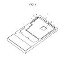
FIG. 1 illustrates an example of a heat-transfer plate according to a first embodiment; -
FIG. 2 illustrates a first example of a resin-amount check portion in the heat-transfer plate according to the first embodiment; -
FIG. 3 illustrates the first example of the resin-amount check portion in the heat-transfer plate according to the first embodiment; -
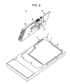
FIG. 4 illustrates an example of a heat-transfer plate module according to embodiments; -
FIG. 5 illustrates the example of the heat-transfer plate module according to embodiments; -
FIG. 6 illustrates a state where thermally-conductive resin is accumulated in the resin-amount check portion illustrated inFIG. 2 ; -
FIG. 7 is a cross-sectional view taken along a line VII-VII inFIG. 6 ; -
FIG. 8 is a cross-sectional view taken along a line VIII-VIII inFIG. 6 ; -
FIG. 9 illustrates a second example of the resin-amount check portion in the heat-transfer plate according to a second embodiment; -
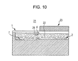
FIG. 10 illustrates a state where the thermally-conductive resin is accumulated in the resin-amount check portion illustrated inFIG. 9 ; -
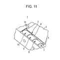
FIG. 11 illustrates a third example of the resin-amount check portion in the heat-transfer plate according to a third embodiment; -
FIG. 12 illustrates a state where the thermally-conductive resin is accumulated in the resin-amount check portion illustrated inFIG. 11 ; -
FIG. 13 is a cross-sectional view taken along a line XIII-XIII inFIG. 12 ; -
FIG. 14 is a cross-sectional view taken along a line XIV-XIV inFIG. 12 ; -
FIG. 15 illustrates a fourth example of the resin-amount check portion in the heat-transfer plate according to a fourth embodiment; -
FIG. 16 illustrates a state where the thermally-conductive resin is accumulated in the resin-amount check portion illustrated inFIG. 15 ; -
FIG. 17 is a cross-sectional view taken along a line XVII-XVII inFIG. 16 ; -
FIG. 18 is a cross-sectional view taken along a line XVIII-XVIII inFIG. 16 ; and -
FIG. 19 illustrates an example of a submarine apparatus according to a fifth embodiment. - In a technology in which thermally-conductive resin is loaded between an electronic component and a planar thermal conductor and heat generated at the electronic component is made to escape to the thermal conductor, it may be difficult to check whether or not an air bubble is contained in the thermally-conductive resin. If an air bubble is contained in the thermally-conductive resin, the thermal conductivity of the thermally-conductive resin would decrease, thus making it difficult to allow the heat generated at the electronic component to efficiently escape to the thermal conductor.
- Preferred embodiments of a heat-transfer plate, a heat-transfer plate module, and a submarine apparatus that allow for checking of whether or not the thermally-conductive resin loaded therein contains an air bubble will be described below with reference to the appended drawings.
-
FIG. 1 illustrates an example of a heat-transfer plate according to a first embodiment.FIGs. 2 and3 illustrate a first example of a resin-amount check portion in the heat-transfer plate according to the first embodiment. - As illustrated in
FIGs. 1 to 3 , a heat-transfer plate 1 has apool portion 2, a resin-amount check portion 3, alevee portion 4, and aflow channel 5. The heat-transfer plate 1 is fixed to a printed circuit board (not illustrated) mounted with heat-generating heating components and radiates the heat from the heating components. The heat-transfer plate 1 is composed of a material with high thermal conductivity. For example, the heat-transfer plate 1 may be composed of metal, such as copper, aluminum, stainless steel, a titanium alloy, or beryllium copper. Alternatively, the heat-transfer plate 1 may be composed of a resin material that does not produce outgas. - The
pool portion 2 is provided by depressing a part of a surface of the heat-transfer plate 1. Thepool portion 2 may have a recess 6 in one area that is deeper than the remaining area. Thepool portion 2 is to be loaded with thermally-conductive resin (not illustrated) having high thermal conductivity. The thermally-conductive resin comes into contact with the heating components of the printed circuit board and transfers the heat from the heating components to the heat-transfer plate 1. In the printed circuit board (not illustrated), a heating component with a large component height may be disposed at a position corresponding to the recess 6 in thepool portion 2, and a heating component with a small component height may be disposed at a position corresponding to an area other than the recess 6 in thepool portion 2. - The resin-
amount check portion 3 is positioned where the thermally-conductive resin is viewable in the state where the printed circuit board is fixed to the heat-transfer plate 1. For example, in the example illustrated inFIG. 1 , the resin-amount check portion 3 is provided between thepool portion 2 and an area along one edge of the heat-transfer plate 1 that is not covered by the printed circuit board. The resin-amount check portion 3 has multiple depths. An operator may check the amount of thermally-conductive resin based on how much the thermally-conductive resin is accumulated in the resin-amount check portion 3. - In the first example of the resin-
amount check portion 3, the resin-amount check portion 3 may have multiplerecessed measurement portions 7 to 10 having different depths. For example, in the example illustrated inFIGs. 1 to 3 , the resin-amount check portion 3 is provided with four measurement portions, namely, afirst measurement portion 7, asecond measurement portion 8, athird measurement portion 9, and afourth measurement portion 10. Themeasurement portions 7 to 10 may have the same capacity or different capacities. For example, the capacity of each of themeasurement portions 7 to 10 may be about 0.1 cc. The shape of each of themeasurement portions 7 to 10 is not limited to a cylindrical shape, but may be any shape so long as the thermally-conductive resin may be accumulated therein. - The
levee portion 4 is provided between thepool portion 2 and the resin-amount check portion 3 and extends upright from the bottom of thepool portion 2. Thelevee portion 4 suppresses flow of the thermally-conductive resin from thepool portion 2 toward the resin-amount check portion 3. - The
flow channel 5 is provided between thepool portion 2 and the resin-amount check portion 3. Theflow channel 5 serves as a path through which the thermally-conductive resin flows into the resin-amount check portion 3 from thepool portion 2. In other words, the thermally-conductive resin flows into the resin-amount check portion 3 from thepool portion 2 by traveling through theflow channel 5. In thelevee portion 4, an area thereof that is lower than the periphery of thepool portion 2 serves as theflow channel 5. In the first example of the resin-amount check portion 3, for example, an area of thelevee portion 4 that corresponds to thefirst measurement portion 7 is lower than the periphery of thepool portion 2. Therefore, the thermally-conductive resin spilling over thepool portion 2 travels through theflow channel 5 so as to flow into thefirst measurement portion 7 of the resin-amount check portion 3. - In the
levee portion 4, asecond flow channel 11 that is lower than theflow channel 5 is provided in an area between thefirst measurement portion 7 and thesecond measurement portion 8. The thermally-conductive resin spilling over thefirst measurement portion 7 travels through thesecond flow channel 11 so as to flow into thesecond measurement portion 8. Likewise, the thermally-conductive resin spilling over thesecond measurement portion 8 travels through athird flow channel 12, which is provided between thesecond measurement portion 8 and thethird measurement portion 9 and is lower than thesecond flow channel 11, so as to flow into thethird measurement portion 9. The thermally-conductive resin spilling over thethird measurement portion 9 travels through afourth flow channel 13, which is provided between thethird measurement portion 9 and thefourth measurement portion 10 and is lower than thethird flow channel 12, so as to flow into thefourth measurement portion 10. - When the thermally-conductive resin accumulates in the
pool portion 2 and the heating components of the printed circuit board are immersed into the thermally-conductive resin in thepool portion 2, the thermally-conductive resin spills over thepool portion 2. For example, a state where thefirst measurement portion 7 is filled with the thermally-conductive resin spilling over thepool portion 2, the thermally-conductive resin spilling over thefirst measurement portion 7 accumulates in thesecond measurement portion 8, and the third andfourth measurement portions pool portion 2, the amount of thermally-conductive resin spilling over thepool portion 2 decreases. Thus, for example, the thermally-conductive resin accumulates in thefirst measurement portion 7, but the second tofourth measurement portions 8 to 10 are empty. - On the other hand, if the thermally-conductive resin in the
pool portion 2 contains an air bubble, the amount of thermally-conductive resin spilling over thepool portion 2 increases. Thus, for example, thefirst measurement portion 7 and thesecond measurement portion 8 become filled with the thermally-conductive resin, the thermally-conductive resin accumulates in thethird measurement portion 9, and thefourth measurement portion 10 is empty. If there are many air bubbles contained in the thermally-conductive resin, thethird measurement portion 9 may also become filled with the thermally-conductive resin, and the thermally-conductive resin may accumulate in thefourth measurement portion 10. - Alternatively, for example, a state where the
first measurement portion 7 and thesecond measurement portion 8 are filled with the thermally-conductive resin spilling over thepool portion 2, the thermally-conductive resin spilling over thesecond measurement portion 8 accumulates in thethird measurement portion 9, and thefourth measurement portion 10 is empty may be defined as a preferred state. For example, if the heating component with the large height is immersed in the thermally-conductive resin in thepool portion 2 but the heating component with the small height is not immersed in the thermally-conductive resin, the amount of thermally-conductive resin spilling over thepool portion 2 decreases significantly. Thus, for example, the thermally-conductive resin accumulates in thefirst measurement portion 7, but the second tofourth measurement portions 8 to 10 are empty. - If the heating component with the large height and the heating component with the small height are both immersed in the thermally-conductive resin in the
pool portion 2 but are not sufficiently immersed therein, the amount of thermally-conductive resin spilling over thepool portion 2 decreases. Thus, for example, thefirst measurement portion 7 becomes filled with the thermally-conductive resin, the thermally-conductive resin accumulates in thesecond measurement portion 8, and the third andfourth measurement portions - If an air bubble is contained in the thermally-conductive resin in the
pool portion 2, the amount of thermally-conductive resin spilling over thepool portion 2 increases. Thus, for example, the first tothird measurement portions 7 to 9 become filled with the thermally-conductive resin, and the thermally-conductive resin accumulates in thefourth measurement portion 10. If there are many air bubbles contained in the thermally-conductive resin, thefourth measurement portion 10 may also become filled with the thermally-conductive resin. - The number of measurement portions may be three, or may be five or more. For example, it is assumed that three measurement portions are provided, namely, the
first measurement portion 7, thesecond measurement portion 8 and thethird measurement portion 9. In that case, a state where thefirst measurement portion 7 becomes filled with the thermally-conductive resin spilling over thepool portion 2, the thermally-conductive resin spilling over thefirst measurement portion 7 accumulates in thesecond measurement portion 8, and thethird measurement portion 9 is empty may be defined as a preferred state. - According to the heat-
transfer plate 1 illustrated inFIGs. 1 to 3 , since the resin-amount check portion 3 is not covered with the printed circuit board, the operator may visually check the resin-amount check portion 3 even when the printed circuit board is attached to the heat-transfer plate 1. Furthermore, if the thermally-conductive resin loaded in thepool portion 2 contains an air bubble during the attachment process of the printed circuit board, the amount of thermally-conductive resin spilling over thepool portion 2 and accumulated in the resin-amount check portion 3 would increase. Thus, the operator may check the amount of thermally-conductive resin accumulated in the resin-amount check portion 3 during the attachment process of the printed circuit board so as to check whether or not an air bubble is contained in the thermally-conductive resin loaded in thepool portion 2. In other words, the operator may confirm that there are no air bubbles contained in the thermally-conductive resin loaded in thepool portion 2. - Furthermore, according to the heat-
transfer plate 1 illustrated inFIGs. 1 to 3 , the operator may check the amount of thermally-conductive resin accumulated in the resin-amount check portion 3 during the attachment process of the printed circuit board so as to check whether or not the heating components of the printed circuit board are sufficiently immersed in the thermally-conductive resin in thepool portion 2. Moreover, according to the heat-transfer plate 1 illustrated inFIGs. 1 to 3 , since the resin-amount check portion 3 hasmultiple measurement portions 7 to 10, the amount of thermally-conductive resin accumulated in the resin-amount check portion 3 may be checked with high accuracy. Furthermore, according to the heat-transfer plate 1 illustrated inFIGs. 1 to 3 , since the area of thelevee portion 4 that is lower than the periphery of thepool portion 2 serves as theflow channel 5, the thermally-conductive resin may be made to flow from thepool portion 2 to the resin-amount check portion 3 when the heating components are immersed into the thermally-conductive resin in thepool portion 2. -
FIGs. 4 and5 illustrate an example of a heat-transfer plate module according to embodiments.FIG. 4 illustrates a state where the printed circuit board is not attached to the heat-transfer plate yet, andFIG. 5 illustrates a state where the printed circuit board is attached to the heat-transfer plate. As illustrated inFIGs. 4 and5 , a heat-transfer plate module 21 includes, for example, the heat-transfer plate 1 illustrated inFIGs. 1 to 3 , thermally-conductive resin 22, and a printedcircuit board 23. - The thermally-
conductive resin 22 is to be accumulated into thepool portion 2 of the heat-transfer plate 1. The thermally-conductive resin 22 has fluidity and is in the form of liquid or sol when being accumulated into thepool portion 2 of the heat-transfer plate 1, and subsequently solidifies. As an example of the thermally-conductive resin 22, for example, ceramic filler silicone, such as 65-00-1642-0000 of CHO-THERM 1642 (manufactured by Chomerics Ltd.) or 65-00-1641-0000 or 65-01-1641-0000 of CHO-THERM 1641 (manufactured by Chomerics Ltd.), may be used. - In a state where the printed
circuit board 23 is not attached to the heat-transfer plate 1 yet, the liquid level of the thermally-conductive resin 22 in thepool portion 2 may be, for example, lower than the height of theflow channel 5 in thelevee portion 4 or equal to the height of theflow channel 5 in thelevee portion 4. Thus, in the state where the printedcircuit board 23 is not attached to the heat-transfer plate 1 yet, the thermally-conductive resin 22 does not flow into the resin-amount check portion 3. In other words, in the state where the printedcircuit board 23 is not attached to the heat-transfer plate 1 yet, the resin-amount check portion 3 is empty. - The surface of the printed
circuit board 23 that faces the heat-transfer plate 1 is mounted withheating components 24. Theheating components 24 may include a heating component with a large height and a heating component with a small height. Theheating components 24 may be surface mounting devices (SMDs) or insertion mounting devices (IMDs). In a state where the printedcircuit board 23 is attached to the heat-transfer plate 1, theheating components 24 are immersed in the thermally-conductive resin 22 within thepool portion 2. - The surface of the printed
circuit board 23 opposite the surface thereof facing the heat-transfer plate 1 has attached thereto various electronic-circuit components 25 and optical-communication components 26, such as optical connectors. With regard to the electronic-circuit components 25 and the optical-communication components 26, some of the components are illustrated, whereas the remaining components have been omitted from the drawings. - The printed
circuit board 23 may be fixed to the heat-transfer plate 1 by using, for example, screw members (not illustrated). InFIGs. 2 and3 ,reference numeral 14 denotes screw holes provided in the heat-transfer plate 1 for receiving the screw members used for fixing the printedcircuit board 23 to the heat-transfer plate 1. -
FIG. 6 illustrates a state where the thermally-conductive resin 22 is accumulated in the resin-amount check portion 3 illustrated inFIG. 2 . In the state illustrated inFIG. 6 , thefirst measurement portion 7 is filled with the thermally-conductive resin 22, the thermally-conductive resin 22 is accumulated in thesecond measurement portion 8, and the third andfourth measurement portions FIG. 6 ,reference numeral 27 denotes through-holes provided in the printedcircuit board 23 for inserting the screw members used for fixing the printedcircuit board 23 to the heat-transfer plate 1. -
FIG. 7 is a cross-sectional view taken along a line VII-VII inFIG. 6 . The line VII-VII extends through thefirst measurement portion 7 inFIG. 6 in a direction that intersects the direction in which the first tofourth measurement portions 7 to 10 are arranged. - As illustrated in
FIG. 7 , in the state where the printedcircuit board 23 is attached to the heat-transfer plate 1, the height of the liquid level of the thermally-conductive resin 22 in thepool portion 2 may be, for example, equal to the height of theflow channel 5 between thepool portion 2 and thefirst measurement portion 7. The thermally-conductive resin 22 spilling over thepool portion 2 travels through theflow channel 5 so as to flow into thefirst measurement portion 7. -
FIG. 8 is a cross-sectional view taken along a line VIII-VIII inFIG. 6 . The line VIII-VIII extends through the first tofourth measurement portions 7 to 10 inFIG. 6 . As illustrated inFIG. 8 , the thermally-conductive resin 22 spilling over thefirst measurement portion 7 travels through thesecond flow channel 11 between thefirst measurement portion 7 and thesecond measurement portion 8 so as to flow into thesecond measurement portion 8. The thermally-conductive resin 22 spilling over thesecond measurement portion 8 travels through thethird flow channel 12 between thesecond measurement portion 8 and thethird measurement portion 9 so as to flow into thethird measurement portion 9. The thermally-conductive resin 22 spilling over thethird measurement portion 9 travels through thefourth flow channel 13 between thethird measurement portion 9 and thefourth measurement portion 10 so as to flow into thefourth measurement portion 10. - When assembling the heat-
transfer plate module 21, the operator first measures the mass and the volume of the thermally-conductive resin 22 by using a container, such as a beaker or a graduated cylinder, and also calculates the volume of the thermally-conductive resin 22 from the mass thereof by using the specific gravity or the density of the thermally-conductive resin 22. Even if the thermally-conductive resin 22 contains an air bubble at the time of the measurement process of the thermally-conductive resin 22, the mass of the air bubble is zero. Therefore, the mass of the thermally-conductive resin 22 containing an air bubble is the same as the mass of the thermally-conductive resin 22 not containing an air bubble. Consequently, the volume calculated from, for example, the specific gravity and the measured value of the mass is equal to the volume of the thermally-conductive resin 22 not containing an air bubble. - The operator compares the measured value and the calculated value of the volume. If the measured value of the volume is larger than the calculated value, the operator may determine that the thermally-
conductive resin 22 contains an air bubble at the time of the measurement process. If the measured value of the volume is equal to the calculated value, the operator may determine that the thermally-conductive resin 22 does not contain an air bubble at the time of the measurement process. If the operator determines that the thermally-conductive resin 22 contains an air bubble at the time of the measurement process, the operator performs a process for removing the air bubble from the thermally-conductive resin 22 before pouring the thermally-conductive resin 22 into thepool portion 2 of the heat-transfer plate 1. - While holding the heat-
transfer plate 1 horizontally by using, for example, a level, the operator pours the thermally-conductive resin 22 not containing an air bubble into thepool portion 2 of the heat-transfer plate 1 until, for example, the liquid level of the thermally-conductive resin 22 reaches the height of theflow channel 5 in thelevee portion 4. Subsequently, the operator attaches the printedcircuit board 23, which is preliminarily mounted with theheating components 24, the electronic-circuit components 25, and the optical-communication components 26, to the heat-transfer plate 1 such that theheating components 24 are immersed in the thermally-conductive resin 22 in thepool portion 2. - Then, the operator checks the amount of thermally-
conductive resin 22 spilling over thepool portion 2 and flowing into the resin-amount check portion 3 owing to the immersion of theheating components 24 in the thermally-conductive resin 22 in thepool portion 2. If the amount of thermally-conductive resin 22 measured at the resin-amount check portion 3 is smaller than a predetermined amount, the operator may determine that theheating components 24 are not sufficiently immersed in the thermally-conductive resin 22. One of the reasons for the insufficient immersion of theheating components 24 in the thermally-conductive resin 22 may be that the printedcircuit board 23 is significantly warped, causing one or some of theheating components 24 to not come into contact with the thermally-conductive resin 22 and be set in a floating position. In this case, the operator may detach the printedcircuit board 23 from the heat-transfer plate 1, unwarp the printedcircuit board 23, and then attach the printedcircuit board 23 to the heat-transfer plate 1 again. - If the amount of thermally-
conductive resin 22 measured at the resin-amount check portion 3 is larger than the predetermined amount, the operator may determine that an air bubble is contained in the thermally-conductive resin 22 during the process of immersing theheating components 24 into the thermally-conductive resin 22. In this case, the operator may detach the printedcircuit board 23 from the heat-transfer plate 1, crush the air bubble contained in the thermally-conductive resin 22 by using a sharp-ended tool, such as a nail, and then attach the printedcircuit board 23 to the heat-transfer plate 1 again. - If the amount of thermally-
conductive resin 22 measured at the resin-amount check portion 3 is equal to the predetermined amount, the operator fixes the printedcircuit board 23 to the heat-transfer plate 1 by using the screw members. When the thermally-conductive resin 22 solidifies, the assembly process of the heat-transfer plate module 21 is completed. - According to the heat-
transfer plate module 21 illustrated inFIGs. 4 to 8 , the operator may check whether an air bubble is not contained in the thermally-conductive resin 22 loaded in thepool portion 2 during the attachment process of the printedcircuit board 23. If the thermally-conductive resin 22 contains an air bubble, the operator may crush the air bubble and attach the printedcircuit board 23 to the heat-transfer plate 1 in a state where there are no air bubbles contained in the thermally-conductive resin 22, whereby a heat-transfer plate module 21 with high thermal conductivity is obtained. - Furthermore, according to the heat-
transfer plate module 21 illustrated inFIGs. 4 to 8 , the operator may check whether theheating components 24 of the printedcircuit board 23 are sufficiently immersed in the thermally-conductive resin 22 during the attachment process of the printedcircuit board 23. If theheating components 24 are not sufficiently immersed in the thermally-conductive resin 22, the operator may unwarp the printedcircuit board 23 and then attach the printedcircuit board 23 to the heat-transfer plate 1, whereby a heat-transfer plate module 21 with high thermal conductivity is obtained. -
FIG. 9 illustrates a second example of the resin-amount check portion 3 in the heat-transfer plate 1 according to a second embodiment.FIG. 10 is a cross-sectional view corresponding to that taken along the line VII-VII inFIG. 6 and illustrates a state where the thermally-conductive resin 22 is accumulated in the resin-amount check portion 3 illustrated inFIG. 9 . InFIG. 10 , a cross portion corresponding to that taken along the line VIII-VIII inFIG. 6 is the same as that inFIG. 8 . - As illustrated in
FIGs. 9 and10 , in the second example of the resin-amount check portion 3, an area of thelevee portion 4 located between thepool portion 2 and thefirst measurement portion 7 of the resin-amount check portion 3 in the heat-transfer plate 1 is provided with a through-hole serving as aflow channel 28. In other words, thepool portion 2 and thefirst measurement portion 7 are connected to each other via theflow channel 28. Therefore, the thermally-conductive resin 22 flows into thefirst measurement portion 7 from thepool portion 2 by traveling through theflow channel 28. - According to the heat-
transfer plate 1 illustrated inFIG. 9 and the heat-transfer plate module 21 illustrated inFIG. 10 , since thepool portion 2 and the resin-amount check portion 3 are connected to each other via theflow channel 28, the thermally-conductive resin 22 may be made to flow toward the resin-amount check portion 3 from thepool portion 2 when theheating components 24 are immersed into the thermally-conductive resin 22 in thepool portion 2. -
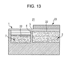
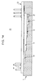
FIG. 11 illustrates a third example of the resin-amount check portion 3 in the heat-transfer plate 1 according to a third embodiment.FIG. 12 illustrates a state where the thermally-conductive resin 22 is accumulated in the resin-amount check portion 3 illustrated inFIG. 11 .FIG. 13 is a cross-sectional view taken along a line XIII-XIII inFIG. 12 . The line XIII-XIII extends through thefirst measurement portion 7 inFIG. 12 in a direction that intersects the direction in which the first tofourth measurement portions 7 to 10 are arranged.FIG. 14 is a cross-sectional view taken along a line XIV-XIV inFIG. 12 . The line XIV-XIV extends through the first tofourth measurement portions 7 to 10 inFIG. 12 . - As illustrated in
FIGs. 11 to 14 , in the third example of the resin-amount checking portion 3, the first tofourth measurement portions 7 to 10 are provided in a stepped manner in the resin-amount check portion 3. The depths of the first tofourth measurement portions 7 to 10 vary in a stepwise fashion such that thefirst measurement portion 7 is the deepest and thefourth measurement portion 10 is the shallowest. - The thermally-
conductive resin 22 flowing from thepool portion 2 in the heat-transfer plate 1 to the resin-amount check portion 3 by traveling through theflow channel 5, which is a low area of thelevee portion 4, first accumulates in thefirst measurement portion 7, which is the deepest portion. When the amount of thermally-conductive resin 22 flowing into the resin-amount check portion 3 increases, the liquid level of the thermally-conductive resin 22 in the resin-amount check portion 3 rises. When the liquid level of the thermally-conductive resin 22 in the resin-amount check portion 3 reaches the bottom of thesecond measurement portion 8, the thermally-conductive resin 22 spreads toward thesecond measurement portion 8 and begins to accumulate in thesecond measurement portion 8. As the amount of thermally-conductive resin 22 flowing into the resin-amount check portion 3 continues to increase, the thermally-conductive resin 22 spreads toward thethird measurement portion 9 and accumulates in thethird measurement portion 9, and further spreads toward thefourth measurement portion 10 and accumulates in thefourth measurement portion 10. - According to the heat-
transfer plate 1 illustrated inFIG. 11 and the heat-transfer plate module 21 illustrated inFIGs. 12 to 14 , since the first tofourth measurement portions 7 to 10 are provided in a stepped manner in the resin-amount checking portion 3, the operator may check the amount of thermally-conductive resin 22 accumulated in the resin-amount check portion 3 during the attachment process of the printedcircuit board 23. Therefore, the operator may check whether an air bubble is not contained in the thermally-conductive resin 22 loaded in thepool portion 2. Furthermore, the operator may check whether or not theheating components 24 of the printedcircuit board 23 are sufficiently immersed in the thermally-conductive resin 22 in thepool portion 2. - In the third example of the resin-
amount check portion 3, thepool portion 2 and thefirst measurement portion 7 may be connected to each other via theflow channel 28 extending through thelevee portion 4, as in the second example of the resin-amount check portion 3 illustrated inFIG. 9 , and the thermally-conductive resin 22 may flow toward thefirst measurement portion 7 from thepool portion 2 by traveling through thisflow channel 28. Furthermore, in the resin-amount check portion 3, the number of measurement portions, that is, the number of steps, is not limited to four. -
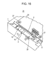
FIG. 15 illustrates a fourth example of the resin-amount check portion 3 in the heat-transfer plate 1 according to a fourth embodiment.FIG. 16 illustrates a state where the thermally-conductive resin 22 is accumulated in the resin-amount check portion 3 illustrated inFIG. 15 .FIG. 17 is a cross-sectional view taken along a line XVII-XVII inFIG. 16 . The line XVII-XVII extends in the lateral direction of ameasurement portion 15 inFIG. 16 through near the deepest area of themeasurement portion 15.FIG. 18 is a cross-sectional view taken along a line XVIII-XVIII inFIG. 16 . The line XVIII-XVIII extends through themeasurement portion 15 inFIG. 16 in the longitudinal direction of themeasurement portion 15. - As illustrated in
FIGs. 15 to 18 , in the fourth example of the resin-amount check portion 3, the bottom surface of themeasurement portion 15 in the resin-amount check portion 3 is sloped such that an area in thismeasurement portion 15 into which the thermally-conductive resin 22 flows from thepool portion 2 of the heat-transfer plate 1 is the deepest. The bottom surface of themeasurement portion 15 is provided with ascale 16. Alternatively, thescale 16 may be provided at a side surface of themeasurement portion 15. - The thermally-
conductive resin 22 flowing into the resin-amount check portion 3 from thepool portion 2 in the heat-transfer plate 1 by traveling through theflow channel 5, which is a low area of thelevee portion 4, accumulates in the deep area of themeasurement portion 15. When the amount of thermally-conductive resin 22 flowing into the resin-amount check portion 3 increases, the liquid level of the thermally-conductive resin 22 in the resin-amount check portion 3 rises. Then, the thermally-conductive resin 22 gradually spreads toward a shallow area of themeasurement portion 15. - According to the heat-
transfer plate 1 illustrated inFIG. 15 and the heat-transfer plate module 21 illustrated inFIGs. 16 to 18 , since the bottom of themeasurement portion 15 in the resin-amount check portion 3 is sloped and is provided with thescale 16, the operator may check the amount of thermally-conductive resin 22 accumulated in the resin-amount check portion 3 during the attachment process of the printedcircuit board 23. Therefore, the operator may check whether an air bubble is not contained in the thermally-conductive resin 22 loaded in thepool portion 2. Furthermore, the operator may check whether or not theheating components 24 of the printedcircuit board 23 are sufficiently immersed in the thermally-conductive resin 22 in thepool portion 2. - In the fourth example of the resin-
amount check portion 3, thepool portion 2 and themeasurement portion 15 may be connected to each other via theflow channel 28 extending through thelevee portion 4, as in the second example of the resin-amount check portion 3 illustrated inFIG. 9 , and the thermally-conductive resin 22 may flow toward themeasurement portion 15 from thepool portion 2 by traveling through thisflow channel 28. - The heat-
transfer plate 1 or the heat-transfer plate module 21 illustrated inFIGs. 1 to 18 have the printedcircuit board 23 mounted with theheating components 24 and may be used in an apparatus, such as an electronic apparatus, in which cooling of theheating components 24 is desired. For example, the heat-transfer plate 1 or the heat-transfer plate module 21 illustrated inFIGs. 1 to 18 may be used in an apparatus in which cooling of theheating components 24 by using a fan is difficult. An example of such an apparatus in which cooling of theheating components 24 by using a fan is difficult includes an apparatus having a lifespan that is longer than that of a fan motor, such as a submarine apparatus that serves as an optical relay apparatus used in an optical transmission system and that relays an optical signal at the seafloor. -
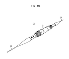
FIG. 19 illustrates an example of asubmarine apparatus 31 according to a fifth embodiment. As illustrated inFIG. 19 , in thesubmarine apparatus 31, the above-described heat-transfer plate module 21 is sealed within ahousing 32 that is resistant to pressure. Both ends of thesubmarine apparatus 31 are connected tosubmarine cables 33 each having a bundle of optical fibers.
Claims (8)
- A heat-transfer plate that is fixed to a printed circuit board mounted with a heating component and that radiates heat from the heating component, the heat-transfer plate comprising:a pool portion configured to have a partially-depressed surface and to be loaded with thermally-conductive resin that is in contact with the heating component so as to transfer the heat from the heating component to the heat-transfer plate;a resin-amount check portion configured to have a plurality of depths and to be disposed at a position where the thermally-conductive resin is viewable in a state where the printed circuit board is fixed to the heat-transfer plate;a levee portion configured to be provided between the pool portion and the resin-amount check portion and to suppress flow of the thermally-conductive resin toward the resin-amount check portion; anda flow channel configured to be provided between the pool portion and the resin-amount check portion and to serve as a path through which the thermally-conductive resin flowing into the resin-amount check portion from the pool portion travels.
- The heat-transfer plate according to claim 1, wherein the resin-amount check portion has a plurality of recessed measurement portions having different depths.
- The heat-transfer plate according to claim 1, wherein the resin-amount check portion has a stepped measurement portion.
- The heat-transfer plate according to claim 1, wherein the resin-amount check portion has a measurement portion whose bottom is sloped and a scale that indicates an amount of the thermally-conductive resin.
- The heat-transfer plate according to any one of claims 1 to 4, wherein a part of the levee portion is lower than a periphery of the pool portion, and the part of the levee portion that is lower than the periphery of the pool portion serves as the flow channel.
- The heat-transfer plate according to any one of claims 1 to 4, wherein the flow channel is a hole that extends through the levee portion and connects the pool portion and the resin-amount check portion.
- A heat-transfer plate module comprising:a heat-transfer plate configured to radiate heat from a heating component including
a pool portion configured to have a partially-depressed surface and to be loaded with thermally-conductive resin that is in contact with the heating component so as to transfer the heat from the heating component to the heat-transfer plate,
a resin-amount check portion configured to have a plurality of depths and to be disposed at a position where the thermally-conductive resin is viewable in a state where the printed circuit board is fixed to the heat-transfer plate,
a levee portion configured to be provided between the pool portion and the resin-amount check portion and to suppress flow of the thermally-conductive resin toward the resin-amount check portion, and
a flow channel configured to be provided between the pool portion and the resin-amount check portion and to serve as a path through which the thermally-conductive resin flowing into the resin-amount check portion from the pool portion travels; anda printed circuit board configured to be mounted with the heating component and to be fixed to the heat-transfer plate. - A submarine apparatus comprising:a housing; anda heat-transfer plate module sealed within the housing, including
a heat-transfer plate configured to radiate heat from a heating component including
a pool portion configured to have a partially-depressed surface and to be loaded with thermally-conductive resin that is in contact with the heating component so as to transfer the heat from the heating component to the heat-transfer plate,
a resin-amount check portion configured to have a plurality of depths and to be disposed at a position where the thermally-conductive resin is viewable in a state where the printed circuit board is fixed to the heat-transfer plate,
a levee portion configured to be provided between the pool portion and the resin-amount check portion and to suppress flow of the thermally-conductive resin toward the resin-amount check portion, and
a flow channel configured to be provided between the pool portion and the resin-amount check portion and to serve as a path through which the thermally-conductive resin flowing into the resin-amount check portion from the pool portion travels; and
a printed circuit board configured to be mounted with the heating component and to be fixed to the heat-transfer plate.
Applications Claiming Priority (1)
| Application Number | Priority Date | Filing Date | Title |
|---|---|---|---|
| JP2013123754A JP6079461B2 (en) | 2013-06-12 | 2013-06-12 | Heat transfer structure plate, heat transfer structure plate module and undersea equipment |
Publications (3)
| Publication Number | Publication Date |
|---|---|
| EP2814305A2 true EP2814305A2 (en) | 2014-12-17 |
| EP2814305A3 EP2814305A3 (en) | 2015-05-06 |
| EP2814305B1 EP2814305B1 (en) | 2017-08-09 |
Family
ID=50972450
Family Applications (1)
| Application Number | Title | Priority Date | Filing Date |
|---|---|---|---|
| EP14170755.4A Not-in-force EP2814305B1 (en) | 2013-06-12 | 2014-06-02 | Heat-transfer plate, heat-transfer plate module, and submarine apparatus |
Country Status (3)
| Country | Link |
|---|---|
| US (1) | US9226381B2 (en) |
| EP (1) | EP2814305B1 (en) |
| JP (1) | JP6079461B2 (en) |
Cited By (1)
| Publication number | Priority date | Publication date | Assignee | Title |
|---|---|---|---|---|
| JP2018015867A (en) * | 2016-07-29 | 2018-02-01 | 株式会社マキタ | Electric work machine |
Families Citing this family (2)
| Publication number | Priority date | Publication date | Assignee | Title |
|---|---|---|---|---|
| JP2015018971A (en) * | 2013-07-11 | 2015-01-29 | 富士通株式会社 | Heat radiation plate, and submarine apparatus |
| CN113490368B (en) | 2021-07-07 | 2023-03-21 | 台达电子企业管理(上海)有限公司 | Power supply device and high-power lighting system |
Citations (2)
| Publication number | Priority date | Publication date | Assignee | Title |
|---|---|---|---|---|
| JP2001144449A (en) | 1999-11-17 | 2001-05-25 | Nec Corp | Multilayer printed wiring board and its heat dissipation structure |
| JP2004222426A (en) | 2003-01-15 | 2004-08-05 | Mitsubishi Electric Corp | Submarine repeater |
Family Cites Families (16)
| Publication number | Priority date | Publication date | Assignee | Title |
|---|---|---|---|---|
| US4396936A (en) * | 1980-12-29 | 1983-08-02 | Honeywell Information Systems, Inc. | Integrated circuit chip package with improved cooling means |
| US5467251A (en) * | 1993-10-08 | 1995-11-14 | Northern Telecom Limited | Printed circuit boards and heat sink structures |
| JP3551491B2 (en) | 1994-10-07 | 2004-08-04 | 三菱電機株式会社 | Printed circuit board with heat sink |
| US5646826A (en) * | 1995-01-26 | 1997-07-08 | Northern Telecom Limited | Printed circuit board and heat sink arrangement |
| US5796582A (en) * | 1996-11-21 | 1998-08-18 | Northern Telecom Limited | Printed circuit board and heat sink arrangement |
| US6212076B1 (en) * | 1999-02-26 | 2001-04-03 | International Business Machines Corporation | Enhanced heat-dissipating printed circuit board package |
| US6896045B2 (en) * | 2001-10-24 | 2005-05-24 | Cool Shield, Inc. | Structure and method of attaching a heat transfer part having a compressible interface |
| JP3611548B2 (en) * | 2002-02-20 | 2005-01-19 | Tdk株式会社 | Switching power supply and manufacturing method thereof |
| US7057896B2 (en) | 2002-08-21 | 2006-06-06 | Matsushita Electric Industrial Co., Ltd. | Power module and production method thereof |
| US7436584B2 (en) * | 2002-12-13 | 2008-10-14 | Red Sky Subsea, Ltd. | Optical amplifier module housed in a factory cable joint |
| US6870993B2 (en) | 2002-12-13 | 2005-03-22 | Red Sky Systems, Inc. | Interconnect including a repeater for an optical transmission cable |
| JP5142119B2 (en) * | 2006-09-20 | 2013-02-13 | 住友電装株式会社 | Method of manufacturing printed circuit board having heat dissipation structure and heat dissipation structure of printed circuit board manufactured by the method |
| KR20090023886A (en) | 2007-09-03 | 2009-03-06 | 삼성전자주식회사 | Electrical and Electronic Products and Manufacturing Method Thereof |
| JP2009141213A (en) * | 2007-12-07 | 2009-06-25 | Toyota Motor Corp | Semiconductor device and inspection method of semiconductor device |
| FR2953094B1 (en) * | 2009-11-20 | 2011-12-09 | Thales Sa | THERMAL DISSIPATION DEVICE, IN PARTICULAR FOR VERTICAL COMPONENTS AND / OR COMPLEX SHAPE |
| JP2013098388A (en) * | 2011-11-01 | 2013-05-20 | Keihin Corp | Packaging structure of electronic component |
-
2013
- 2013-06-12 JP JP2013123754A patent/JP6079461B2/en not_active Expired - Fee Related
-
2014
- 2014-05-22 US US14/284,920 patent/US9226381B2/en not_active Expired - Fee Related
- 2014-06-02 EP EP14170755.4A patent/EP2814305B1/en not_active Not-in-force
Patent Citations (2)
| Publication number | Priority date | Publication date | Assignee | Title |
|---|---|---|---|---|
| JP2001144449A (en) | 1999-11-17 | 2001-05-25 | Nec Corp | Multilayer printed wiring board and its heat dissipation structure |
| JP2004222426A (en) | 2003-01-15 | 2004-08-05 | Mitsubishi Electric Corp | Submarine repeater |
Cited By (1)
| Publication number | Priority date | Publication date | Assignee | Title |
|---|---|---|---|---|
| JP2018015867A (en) * | 2016-07-29 | 2018-02-01 | 株式会社マキタ | Electric work machine |
Also Published As
| Publication number | Publication date |
|---|---|
| EP2814305A3 (en) | 2015-05-06 |
| EP2814305B1 (en) | 2017-08-09 |
| US20140369004A1 (en) | 2014-12-18 |
| JP2014241366A (en) | 2014-12-25 |
| US9226381B2 (en) | 2015-12-29 |
| JP6079461B2 (en) | 2017-02-15 |
Similar Documents
| Publication | Publication Date | Title |
|---|---|---|
| US10111363B2 (en) | System for effectively transfering heat from electronic devices and method for forming the same | |
| US9226381B2 (en) | Heat-transfer plate, heat-transfer plate module, and submarine apparatus | |
| TWI606766B (en) | Electric machine and its manufacturing method, and design method of electric machine | |
| CN106879222B (en) | Cooling device | |
| EP3124935A1 (en) | Sensor package | |
| US7381905B2 (en) | Structure for fixing an electronic device to a substrate | |
| EP2824702B1 (en) | Heat radiation plate and submarine apparatus | |
| CN106576433B (en) | A printed circuit board | |
| EP2487471A1 (en) | Buoyancy force-based liquid level measurement | |
| JP2014127522A (en) | Heat radiation structure of printed circuit board | |
| CN114846915A (en) | Cooling module | |
| JP2001326306A (en) | Wiring block storage structure | |
| CN214228313U (en) | Vehicle-mounted camera | |
| CN113543540B (en) | Shell and electronic device using same | |
| JP5173788B2 (en) | Electronic circuit device and method for manufacturing electronic circuit device | |
| JP2020174116A (en) | Heat sink fixing member and electronic device | |
| JP2020017570A (en) | Optical module and immersion system | |
| CN117395854A (en) | Circuit board heat radiation structure and manufacturing method thereof | |
| JP2010098242A (en) | Device for accommodating electronic circuit board | |
| JP6045102B2 (en) | Coil component unit, heat dissipation structure thereof, and method of manufacturing coil component unit | |
| US9374897B2 (en) | Printed wiring board | |
| CN107995769B (en) | PCB board with heat dissipation structure design and preparation method thereof | |
| JP5536105B2 (en) | Thermal verification apparatus, apparatus for heat treatment of biological sample, assembly including the thermal verification apparatus, and method for manufacturing the thermal verification apparatus | |
| US6711811B2 (en) | Method to assemble a uniform force hydrostatic bolster plate | |
| CN118210360A (en) | Computer equipment and computing device using immersion cooling mechanism |
Legal Events
| Date | Code | Title | Description |
|---|---|---|---|
| 17P | Request for examination filed |
Effective date: 20140602 |
|
| AK | Designated contracting states |
Kind code of ref document: A2 Designated state(s): AL AT BE BG CH CY CZ DE DK EE ES FI FR GB GR HR HU IE IS IT LI LT LU LV MC MK MT NL NO PL PT RO RS SE SI SK SM TR |
|
| AX | Request for extension of the european patent |
Extension state: BA ME |
|
| PUAI | Public reference made under article 153(3) epc to a published international application that has entered the european phase |
Free format text: ORIGINAL CODE: 0009012 |
|
| PUAL | Search report despatched |
Free format text: ORIGINAL CODE: 0009013 |
|
| AK | Designated contracting states |
Kind code of ref document: A3 Designated state(s): AL AT BE BG CH CY CZ DE DK EE ES FI FR GB GR HR HU IE IS IT LI LT LU LV MC MK MT NL NO PL PT RO RS SE SI SK SM TR |
|
| AX | Request for extension of the european patent |
Extension state: BA ME |
|
| RIC1 | Information provided on ipc code assigned before grant |
Ipc: H05K 3/00 20060101ALN20150405BHEP Ipc: G02B 6/44 20060101ALN20150405BHEP Ipc: H05K 7/20 20060101AFI20150405BHEP Ipc: H05K 3/28 20060101ALN20150405BHEP |
|
| R17P | Request for examination filed (corrected) |
Effective date: 20150820 |
|
| RBV | Designated contracting states (corrected) |
Designated state(s): AL AT BE BG CH CY CZ DE DK EE ES FI FR GB GR HR HU IE IS IT LI LT LU LV MC MK MT NL NO PL PT RO RS SE SI SK SM TR |
|
| REG | Reference to a national code |
Ref country code: DE Ref legal event code: R079 Ref document number: 602014012752 Country of ref document: DE Free format text: PREVIOUS MAIN CLASS: H05K0001020000 Ipc: H05K0007200000 |
|
| GRAP | Despatch of communication of intention to grant a patent |
Free format text: ORIGINAL CODE: EPIDOSNIGR1 |
|
| RIC1 | Information provided on ipc code assigned before grant |
Ipc: G02B 6/50 20060101ALN20170314BHEP Ipc: H05K 3/28 20060101ALN20170314BHEP Ipc: H05K 7/20 20060101AFI20170314BHEP Ipc: G02B 6/44 20060101ALN20170314BHEP Ipc: H05K 3/00 20060101ALN20170314BHEP |
|
| INTG | Intention to grant announced |
Effective date: 20170331 |
|
| GRAS | Grant fee paid |
Free format text: ORIGINAL CODE: EPIDOSNIGR3 |
|
| GRAA | (expected) grant |
Free format text: ORIGINAL CODE: 0009210 |
|
| AK | Designated contracting states |
Kind code of ref document: B1 Designated state(s): AL AT BE BG CH CY CZ DE DK EE ES FI FR GB GR HR HU IE IS IT LI LT LU LV MC MK MT NL NO PL PT RO RS SE SI SK SM TR |
|
| REG | Reference to a national code |
Ref country code: GB Ref legal event code: FG4D |
|
| REG | Reference to a national code |
Ref country code: CH Ref legal event code: EP Ref country code: AT Ref legal event code: REF Ref document number: 918162 Country of ref document: AT Kind code of ref document: T Effective date: 20170815 |
|
| REG | Reference to a national code |
Ref country code: IE Ref legal event code: FG4D |
|
| REG | Reference to a national code |
Ref country code: DE Ref legal event code: R096 Ref document number: 602014012752 Country of ref document: DE |
|
| REG | Reference to a national code |
Ref country code: NL Ref legal event code: MP Effective date: 20170809 |
|
| REG | Reference to a national code |
Ref country code: LT Ref legal event code: MG4D |
|
| REG | Reference to a national code |
Ref country code: AT Ref legal event code: MK05 Ref document number: 918162 Country of ref document: AT Kind code of ref document: T Effective date: 20170809 |
|
| PG25 | Lapsed in a contracting state [announced via postgrant information from national office to epo] |
Ref country code: NO Free format text: LAPSE BECAUSE OF FAILURE TO SUBMIT A TRANSLATION OF THE DESCRIPTION OR TO PAY THE FEE WITHIN THE PRESCRIBED TIME-LIMIT Effective date: 20171109 Ref country code: SE Free format text: LAPSE BECAUSE OF FAILURE TO SUBMIT A TRANSLATION OF THE DESCRIPTION OR TO PAY THE FEE WITHIN THE PRESCRIBED TIME-LIMIT Effective date: 20170809 Ref country code: AT Free format text: LAPSE BECAUSE OF FAILURE TO SUBMIT A TRANSLATION OF THE DESCRIPTION OR TO PAY THE FEE WITHIN THE PRESCRIBED TIME-LIMIT Effective date: 20170809 Ref country code: NL Free format text: LAPSE BECAUSE OF FAILURE TO SUBMIT A TRANSLATION OF THE DESCRIPTION OR TO PAY THE FEE WITHIN THE PRESCRIBED TIME-LIMIT Effective date: 20170809 Ref country code: HR Free format text: LAPSE BECAUSE OF FAILURE TO SUBMIT A TRANSLATION OF THE DESCRIPTION OR TO PAY THE FEE WITHIN THE PRESCRIBED TIME-LIMIT Effective date: 20170809 Ref country code: FI Free format text: LAPSE BECAUSE OF FAILURE TO SUBMIT A TRANSLATION OF THE DESCRIPTION OR TO PAY THE FEE WITHIN THE PRESCRIBED TIME-LIMIT Effective date: 20170809 Ref country code: LT Free format text: LAPSE BECAUSE OF FAILURE TO SUBMIT A TRANSLATION OF THE DESCRIPTION OR TO PAY THE FEE WITHIN THE PRESCRIBED TIME-LIMIT Effective date: 20170809 |
|
| PG25 | Lapsed in a contracting state [announced via postgrant information from national office to epo] |
Ref country code: GR Free format text: LAPSE BECAUSE OF FAILURE TO SUBMIT A TRANSLATION OF THE DESCRIPTION OR TO PAY THE FEE WITHIN THE PRESCRIBED TIME-LIMIT Effective date: 20171110 Ref country code: ES Free format text: LAPSE BECAUSE OF FAILURE TO SUBMIT A TRANSLATION OF THE DESCRIPTION OR TO PAY THE FEE WITHIN THE PRESCRIBED TIME-LIMIT Effective date: 20170809 Ref country code: PL Free format text: LAPSE BECAUSE OF FAILURE TO SUBMIT A TRANSLATION OF THE DESCRIPTION OR TO PAY THE FEE WITHIN THE PRESCRIBED TIME-LIMIT Effective date: 20170809 Ref country code: BG Free format text: LAPSE BECAUSE OF FAILURE TO SUBMIT A TRANSLATION OF THE DESCRIPTION OR TO PAY THE FEE WITHIN THE PRESCRIBED TIME-LIMIT Effective date: 20171109 Ref country code: LV Free format text: LAPSE BECAUSE OF FAILURE TO SUBMIT A TRANSLATION OF THE DESCRIPTION OR TO PAY THE FEE WITHIN THE PRESCRIBED TIME-LIMIT Effective date: 20170809 Ref country code: RS Free format text: LAPSE BECAUSE OF FAILURE TO SUBMIT A TRANSLATION OF THE DESCRIPTION OR TO PAY THE FEE WITHIN THE PRESCRIBED TIME-LIMIT Effective date: 20170809 Ref country code: IS Free format text: LAPSE BECAUSE OF FAILURE TO SUBMIT A TRANSLATION OF THE DESCRIPTION OR TO PAY THE FEE WITHIN THE PRESCRIBED TIME-LIMIT Effective date: 20171209 |
|
| REG | Reference to a national code |
Ref country code: FR Ref legal event code: PLFP Year of fee payment: 5 |
|
| PG25 | Lapsed in a contracting state [announced via postgrant information from national office to epo] |
Ref country code: RO Free format text: LAPSE BECAUSE OF FAILURE TO SUBMIT A TRANSLATION OF THE DESCRIPTION OR TO PAY THE FEE WITHIN THE PRESCRIBED TIME-LIMIT Effective date: 20170809 Ref country code: DK Free format text: LAPSE BECAUSE OF FAILURE TO SUBMIT A TRANSLATION OF THE DESCRIPTION OR TO PAY THE FEE WITHIN THE PRESCRIBED TIME-LIMIT Effective date: 20170809 Ref country code: CZ Free format text: LAPSE BECAUSE OF FAILURE TO SUBMIT A TRANSLATION OF THE DESCRIPTION OR TO PAY THE FEE WITHIN THE PRESCRIBED TIME-LIMIT Effective date: 20170809 |
|
| REG | Reference to a national code |
Ref country code: DE Ref legal event code: R097 Ref document number: 602014012752 Country of ref document: DE |
|
| PG25 | Lapsed in a contracting state [announced via postgrant information from national office to epo] |
Ref country code: SK Free format text: LAPSE BECAUSE OF FAILURE TO SUBMIT A TRANSLATION OF THE DESCRIPTION OR TO PAY THE FEE WITHIN THE PRESCRIBED TIME-LIMIT Effective date: 20170809 Ref country code: SM Free format text: LAPSE BECAUSE OF FAILURE TO SUBMIT A TRANSLATION OF THE DESCRIPTION OR TO PAY THE FEE WITHIN THE PRESCRIBED TIME-LIMIT Effective date: 20170809 Ref country code: EE Free format text: LAPSE BECAUSE OF FAILURE TO SUBMIT A TRANSLATION OF THE DESCRIPTION OR TO PAY THE FEE WITHIN THE PRESCRIBED TIME-LIMIT Effective date: 20170809 Ref country code: IT Free format text: LAPSE BECAUSE OF FAILURE TO SUBMIT A TRANSLATION OF THE DESCRIPTION OR TO PAY THE FEE WITHIN THE PRESCRIBED TIME-LIMIT Effective date: 20170809 |
|
| PLBE | No opposition filed within time limit |
Free format text: ORIGINAL CODE: 0009261 |
|
| STAA | Information on the status of an ep patent application or granted ep patent |
Free format text: STATUS: NO OPPOSITION FILED WITHIN TIME LIMIT |
|
| 26N | No opposition filed |
Effective date: 20180511 |
|
| PG25 | Lapsed in a contracting state [announced via postgrant information from national office to epo] |
Ref country code: SI Free format text: LAPSE BECAUSE OF FAILURE TO SUBMIT A TRANSLATION OF THE DESCRIPTION OR TO PAY THE FEE WITHIN THE PRESCRIBED TIME-LIMIT Effective date: 20170809 |
|
| REG | Reference to a national code |
Ref country code: CH Ref legal event code: PL |
|
| REG | Reference to a national code |
Ref country code: BE Ref legal event code: MM Effective date: 20180630 |
|
| REG | Reference to a national code |
Ref country code: IE Ref legal event code: MM4A |
|
| PG25 | Lapsed in a contracting state [announced via postgrant information from national office to epo] |
Ref country code: LU Free format text: LAPSE BECAUSE OF NON-PAYMENT OF DUE FEES Effective date: 20180602 Ref country code: MC Free format text: LAPSE BECAUSE OF FAILURE TO SUBMIT A TRANSLATION OF THE DESCRIPTION OR TO PAY THE FEE WITHIN THE PRESCRIBED TIME-LIMIT Effective date: 20170809 |
|
| PG25 | Lapsed in a contracting state [announced via postgrant information from national office to epo] |
Ref country code: CH Free format text: LAPSE BECAUSE OF NON-PAYMENT OF DUE FEES Effective date: 20180630 Ref country code: IE Free format text: LAPSE BECAUSE OF NON-PAYMENT OF DUE FEES Effective date: 20180602 Ref country code: LI Free format text: LAPSE BECAUSE OF NON-PAYMENT OF DUE FEES Effective date: 20180630 |
|
| PG25 | Lapsed in a contracting state [announced via postgrant information from national office to epo] |
Ref country code: BE Free format text: LAPSE BECAUSE OF NON-PAYMENT OF DUE FEES Effective date: 20180630 |
|
| PG25 | Lapsed in a contracting state [announced via postgrant information from national office to epo] |
Ref country code: MT Free format text: LAPSE BECAUSE OF NON-PAYMENT OF DUE FEES Effective date: 20180602 |
|
| PG25 | Lapsed in a contracting state [announced via postgrant information from national office to epo] |
Ref country code: TR Free format text: LAPSE BECAUSE OF FAILURE TO SUBMIT A TRANSLATION OF THE DESCRIPTION OR TO PAY THE FEE WITHIN THE PRESCRIBED TIME-LIMIT Effective date: 20170809 |
|
| PG25 | Lapsed in a contracting state [announced via postgrant information from national office to epo] |
Ref country code: HU Free format text: LAPSE BECAUSE OF FAILURE TO SUBMIT A TRANSLATION OF THE DESCRIPTION OR TO PAY THE FEE WITHIN THE PRESCRIBED TIME-LIMIT; INVALID AB INITIO Effective date: 20140602 Ref country code: PT Free format text: LAPSE BECAUSE OF FAILURE TO SUBMIT A TRANSLATION OF THE DESCRIPTION OR TO PAY THE FEE WITHIN THE PRESCRIBED TIME-LIMIT Effective date: 20170809 |
|
| PG25 | Lapsed in a contracting state [announced via postgrant information from national office to epo] |
Ref country code: MK Free format text: LAPSE BECAUSE OF NON-PAYMENT OF DUE FEES Effective date: 20170809 Ref country code: CY Free format text: LAPSE BECAUSE OF FAILURE TO SUBMIT A TRANSLATION OF THE DESCRIPTION OR TO PAY THE FEE WITHIN THE PRESCRIBED TIME-LIMIT Effective date: 20170809 |
|
| PG25 | Lapsed in a contracting state [announced via postgrant information from national office to epo] |
Ref country code: AL Free format text: LAPSE BECAUSE OF FAILURE TO SUBMIT A TRANSLATION OF THE DESCRIPTION OR TO PAY THE FEE WITHIN THE PRESCRIBED TIME-LIMIT Effective date: 20170809 |
|
| PGFP | Annual fee paid to national office [announced via postgrant information from national office to epo] |
Ref country code: GB Payment date: 20220428 Year of fee payment: 9 Ref country code: FR Payment date: 20220510 Year of fee payment: 9 Ref country code: DE Payment date: 20220505 Year of fee payment: 9 |
|
| REG | Reference to a national code |
Ref country code: DE Ref legal event code: R119 Ref document number: 602014012752 Country of ref document: DE |
|
| GBPC | Gb: european patent ceased through non-payment of renewal fee |
Effective date: 20230602 |
|
| PG25 | Lapsed in a contracting state [announced via postgrant information from national office to epo] |
Ref country code: DE Free format text: LAPSE BECAUSE OF NON-PAYMENT OF DUE FEES Effective date: 20240103 Ref country code: GB Free format text: LAPSE BECAUSE OF NON-PAYMENT OF DUE FEES Effective date: 20230602 |
|
| PG25 | Lapsed in a contracting state [announced via postgrant information from national office to epo] |
Ref country code: FR Free format text: LAPSE BECAUSE OF NON-PAYMENT OF DUE FEES Effective date: 20230630 |