EP2814129B2 - Verfahren und Vorrichtung für komplexen, universellen Erdungsfehlerschutz in Hoch- und Mittelspannungssystemen - Google Patents
Verfahren und Vorrichtung für komplexen, universellen Erdungsfehlerschutz in Hoch- und Mittelspannungssystemen Download PDFInfo
- Publication number
- EP2814129B2 EP2814129B2 EP13002965.5A EP13002965A EP2814129B2 EP 2814129 B2 EP2814129 B2 EP 2814129B2 EP 13002965 A EP13002965 A EP 13002965A EP 2814129 B2 EP2814129 B2 EP 2814129B2
- Authority
- EP
- European Patent Office
- Prior art keywords
- current
- protection
- earth fault
- residual current
- phase currents
- Prior art date
- Legal status (The legal status is an assumption and is not a legal conclusion. Google has not performed a legal analysis and makes no representation as to the accuracy of the status listed.)
- Active
Links
Images


Classifications
-
- H—ELECTRICITY
- H02—GENERATION; CONVERSION OR DISTRIBUTION OF ELECTRIC POWER
- H02H—EMERGENCY PROTECTIVE CIRCUIT ARRANGEMENTS
- H02H7/00—Emergency protective circuit arrangements specially adapted for specific types of electric machines or apparatus or for sectionalised protection of cable or line systems, and effecting automatic switching in the event of an undesired change from normal working conditions
- H02H7/22—Emergency protective circuit arrangements specially adapted for specific types of electric machines or apparatus or for sectionalised protection of cable or line systems, and effecting automatic switching in the event of an undesired change from normal working conditions for distribution gear, e.g. bus-bar systems; for switching devices
- H02H7/222—Emergency protective circuit arrangements specially adapted for specific types of electric machines or apparatus or for sectionalised protection of cable or line systems, and effecting automatic switching in the event of an undesired change from normal working conditions for distribution gear, e.g. bus-bar systems; for switching devices for switches
-
- H—ELECTRICITY
- H02—GENERATION; CONVERSION OR DISTRIBUTION OF ELECTRIC POWER
- H02H—EMERGENCY PROTECTIVE CIRCUIT ARRANGEMENTS
- H02H3/00—Emergency protective circuit arrangements for automatic disconnection directly responsive to an undesired change from normal electric working condition with or without subsequent reconnection ; integrated protection
- H02H3/16—Emergency protective circuit arrangements for automatic disconnection directly responsive to an undesired change from normal electric working condition with or without subsequent reconnection ; integrated protection responsive to fault current to earth, frame or mass
- H02H3/162—Emergency protective circuit arrangements for automatic disconnection directly responsive to an undesired change from normal electric working condition with or without subsequent reconnection ; integrated protection responsive to fault current to earth, frame or mass for AC systems
- H02H3/165—Emergency protective circuit arrangements for automatic disconnection directly responsive to an undesired change from normal electric working condition with or without subsequent reconnection ; integrated protection responsive to fault current to earth, frame or mass for AC systems for three-phase systems
Definitions
- the Invention relates to a method and means for earth fault in power high and/or medium voltage system.
- Residual current detection is a key in earth-fault protection systems of power systems.
- WO2004/008600A2 describes protection systems for electrical systems, where the electrical systems may include spot networks and/or grid networks. It is described that the various protection systems may be designed and used to detect and clear faults that may occur within the electrical systems.
- a pair of Rogowski coils may be used to detect current along a conductors at their respective locations on the conductors, and to output corresponding signals to a multi-function, differential relay having multiple voltage and current inputs.
- the differential relay may determine whether a fault exists at some point along the conductors and between the pair of Rogowski coils. Further, the relay may then, in response to the fault, trip a circuit breaker or other network protection device to address the fault.
- an electrical switching apparatus includes a plurality of poles each having a Rogowski coil and a conductor passing through an opening thereof, and a processor circuit including a sensor circuit including a plurality of inputs each electrically interconnected with an output of the Rogowski coil of a corresponding pole.
- the sensor circuit further includes a number of outputs having values each corresponding to current flowing through the conductor, a memory including for each corresponding pole an offset value and a gain correction factor for the sensor circuit, and a gain correction factor for the Rogowski coil, a number of routines, and a processor cooperating with the sensor circuit and the routines to provide for each pole a corrected current value as a function of a corresponding one of the values, the sensor circuit offset value and gain correction factor, and the Rogowski coil gain correction factor.
- a Rogowski coil includes a core, a Rogowski coil winding disposed on the core, an insulator disposed on the Rogowski coil winding disposed on the core, and a conductive winding disposed on the insulator disposed on the Rogowski coil winding disposed on the core.
- the conductive winding includes an electrical connection structured to be grounded. When the conductive winding is grounded, the grounded conductive winding provides electrostatic shielding for the Rogowski coil winding of the Rogowski coil.
- CBCT core balance current transformer
- the output of the transformer is adequate to the residual current of the system below the CBCT in the direction of power flow. That part of the system, which is above the CBCT is not protected by use of that CBCT.
- This first method can be used in electrical network systems with low earth current, e.g. the compensated network. For use in the electrical network system with large earth current this method is expensive.
- the second method of residual current detection uses the phase-current information from the instrument transformers. This information is then summed and the result is the residual current.
- This method can be used in electrical network systems with large earth current, e.g. resistor earthed network. It cannot be used in electrical network system with low earth current due to the sensitivity of current transformers.
- an earth fault protection system for a medium and/or high voltage switchgear as defined in appended claim 8.
- the solution given by the invention is, that for earth fault protection in electrical power system and/or the electrical power system part, for example, but not limited to, protection of the cable connectors, which residual current is determined indirectly by the calculation from the phase current values, obtained from the output signals of Rogowski-coil based current sensors.
- An advantageous embodiment of the invention is, that the Rogowski coil based sensors transform the phase currents to voltage signals and the voltage outputs of the sensors is connected to a protection relay (IED) which digitalizes the voltage values which are then conditioned and then transformed to the value of the measured current, together with the actual phase of it.
- IED protection relay
- a further advantageous step is that the residual current is then determined in the protection relay (IED) as vector sum of the phase current.
- the value of the residual current is then compared to a preset level, and preset measures are taken to setting the alarm and/or switching off the circuit breaker and/or sending the information to the superior system level.
- the residual current value can be displayed on a display of the protection relay (IED), to the operator, or send to a superior control system using digital network.
- IED protection relay
- the sensitive detection of residual current is essential for EF protection, particularly in systems with a low level of earth fault currents.
- a core balanced (ring type) current transformer (CBCT) is typically used.
- CBCT core balanced current transformer
- a typical example is the current sensor which can measure accurately phase currents from a few amps (A) up to tens of kilo-amps (kA). This means that the apparent residual current created by measurement inaccuracy can be very low and therefore there might not be limitation in using the calculated residual current from sensor phase current measurements in any system, even with extremely low levels of earth fault current.
- the senor Due to the absence of a ferromagnetic core the sensor has a linear response over a very wide primary current range, far exceeding the typical current transformer range. Thus, current sensing for both measurement and protection purposes could be realized with single secondary winding.
- one standard sensor can be used for a broad range of rated currents and is also capable of precisely transferring signals containing wide range of frequencies different from rated ones.
- the typical example of a current sensor can reach the metering class 0.5 for continuous current measurement in the extended accuracy range from 5% of the rated primary current (e.g. 4 A) up to the rated continuous thermal current (e.g. 4000 A).
- current sensors can fulfill the requirements of the protection class up to an impressive value reaching the rated short-time thermal current (e.g. 50 kA).
- the zero phase current is calculated as vector sum of phase currents. Phase currents are determined from the digitalized values of the Rogowski coil sensor singals.
- the method is used for generation of switch-off and/or earthing and/or short cutting, by sensitive earth fault protection in power systems.
- the current sensor can be placed at each desired or important region of the power system, for example, but not limited to, inside the switchgear containment, because of its very compact measures.
- Rogowski coils have the advantage in that use, that in absence of iron cores the saturation phenomena is eliminated and therefore dynamic measurement range grows substantially. Since Rogowski coil has linear characteristic, the very accurate measurement is provided in the whole operating range. Then it is possible, to measure reliably and accurate currents much smaller as well as much higher, then it could be possible by conventional current transformes with the same nominal current rating.
- a panel with Rogowski coil based sensors, signal of whose is used for residual current calculation provides significant competitive advantage among other solutions. Residual current can be calculated precisely in wider range than with conventional transformers. High precision sensors can provide information accurate enough to be used in both low and large earth current electrical network systems.
- a calculation algorithm for determination of the sensor signal value is implemented as an exchangeable software-program-product, whiches parameters are adjusted or adjustable to the specific use in the switchgear of other applications, in that way, that the calculation algorithm is transferable into the steering electronic via a data medium, or a data file send via browser.
- Earth fault protection system for switchgears itself, consist of at least one coreless Rogowski coil used for each of a three-phase current path, and that the rogowski coils are combined with protection relays in that way, that residual current of the feeders of the switchgear can be calculated, and in case of a residual current over the preset limit is detected, the earth fault protection is activated.
- the rogowski coil is applied in a thin ringshaped sensor housing, and that the sensor housing has concentric outer ribs, in order to enlarge creepage path along the diameter of the sensor housing ring.
- the advantage of the invention is, that the sensor is small enough to fit in the tight space in the circuit breaker compartment and it has such nominal ratio (80A/150mV), that it can measure the phase currents with accuracy good enough for sufficient I0 calculation.
- the invention ist, that at least one coreless Rogowski coil is used for each of a three-phase current path, and that the rogowski coils are combined with protection relays in that way, that residual current of the feeders of the switchgear can be calculated, and in case of a residual current value reaches preset level, the earth fault protection is activated.
- the rogowski coil is applied in a thin ringshaped sensor housing, and that the sensor housing has concentric outer ribs, in order to enlarge creepage path along the diameter of the sensor housing ring.
- the best placement for the coils is, that the rogowski coil or the rogowski coils are arranged between the ribs.
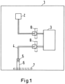
- Figure 1 shows an overview of a medium voltage switchgear panel 1. Inside is shown the busbar 2 and the circuit breaker 3, with higher and lower connection point or terminal. The sensors 8 are located and placed between the cable connector 4 and the connectors of the Circuit breaker 3. So because of the fact, that the rogowski coil sensors are small enough, they can be easily arranged there.
- Modern microprocessor-based protection relays enable calculation of residual current as a vector sum of three phase currents.
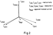
- there is a limitation for application in systems with low level of earth fault currents if conventional CTs are used for phase current measurements. Due to the measurement error of each CT, it is recommended to use calculated residual current like shown in figures 2 and 3 , only if the earth fault current is higher than 10% of nominal current. In other cases it is recommended to use CBCT. The recommendation assumes that CTs with protection accuracy class have been used and therefore limited accuracy of such class is considered with additional safety margin.
- the amplitude and phase errors of the CTs distort measured phase currents.
- the Intelligent Electronic Device (IED) then sees the different phase currents than real phase currents in the network. Consequently apparent residual current is created due to measurement inaccuracy.
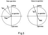
- the level of apparent residual current is usually quite difficult to determine; moreover, this component could affect the correct function of the EF protection. If the apparent residual current is too high in relation to the earth fault current, it could cause malfunction of EF protection (false operation or failure to operation).
- the primary tests of EF protection based on calculated residual current in steady-state conditions were done to determine the level of the apparent residual current.
- the tests were done in a laboratory with the primary current source which supplied the 3-phase current in the range 0-2000 A to the three connected sensors.
- the testing system was connected as an isolated network (without any connection of neutral to the ground), therefore no real residual current could appear. Consequently the trip of earth fault protection could cause only apparent residual current created by measurement inaccuracy.
- the level of apparent residual current was detected by a gradual increase of injected primary current (Ip) and by adjusting of EF protection start current. If the EF protection tripped, the apparent residual current was higher than EF protection start current I0(op).
- the primary current (Ip) was injected in the step 10 A in the range 20 - 1000 A and then in the step 25 A in the range 1000 - 2000 A.
- the primary 3-phase current source was not able to provide exactly 120° phase shift between the phases. This fact resulted in different amplitude values of measured currents in three phases but did not have any impact on measurement accuracy, accuracy of calculated residual current, or EF protection performance since the vector sum of primary phase currents was zero all the time due to the connection of the equipment as an isolated system.
- results of the test signified very promising precondition to decrease recommended setting of EF protection from 10% of nominal current to lower values if the calculated residual current from sensor measurement is used.
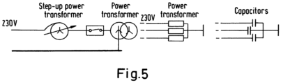
- the model of the network consisted of a supply step-up transformer, circuit breaker, transformer which enabled to create required type of network neutral grounding, and different types of burdens e.g. power transformer for stability test on inrush current or capacitors for earth fault tests.
- FIG. 5 displays a simplified scheme of network model stability test on inrush current.
- Inrush current represents a problematic element for conventional CTs in case that CTs cannot be designed with appropriate parameters (mainly due to limited size or required low-rated primary current).
- Figure 6 displays simplified scheme of connected equipment during the stability test.
- the EF protection in REF615
- the EF protection was set on the most sensitive (minimum) settings:
- the phase currents before the earth fault were approximately 0.5 A.
- the earth fault current was approximately 1.6 A during the tests and EF protection always detected this earth fault current correctly.
- Maximum amplitude deviation between calculated residual current (from 3-phase current sensor measurement) and directly measured residual current (by CBCT) was about 0.1 A. The deviation could be caused by apparent residual current on the side of calculated residual current but on the other side also accuracy of the reference CBCT could be limited due to measurement of such low currents.
- MV sensors based on non-conventional principles represent an alternative way how to measure current and voltage for protection and monitoring purposes in MV systems. Due to their compact size, high level of standardization, negligible energy consumption, high reliability, and safety, many advantages for users and applications exist. Their linear characteristic and very accurate measurement in the whole operating range offer new possibilities in the protection schemes. One area where these benefits could be fully utilized is represented by application with EF protection.
- the results of the tests signified very promising precondition to decrease recommended minimum setting of EF protection, based on calculated residual current from sensor measurement, to lower values than in case of calculated residual current from conventional CTs measurement.
- the whole concept of EF protection based on calculated residual current from sensor measurement will be further verified with the field tests in the networks.
- Figure 8 shows a housing, in which the rogowski coil is arranged.
- the housing has two flange elements at the edges a fixation points.
- the housing has a round inner opening for the conductor.
- the peripherie applied with concentric structures, in order to enlarge the creepage path parallel to the diameters direction.
- the cut along the diameter of the housing makes the enlargement of the creepage lenght visible.
- the inner surface of the housing is metalized to form grounded shielding, and the components forming the Rogowski coil are cast in that housing.
Landscapes
- Engineering & Computer Science (AREA)
- Power Engineering (AREA)
- Measuring Instrument Details And Bridges, And Automatic Balancing Devices (AREA)
- Emergency Protection Circuit Devices (AREA)
Claims (13)
- Verfahren zum Erdfehlerschutz in einer Mittel- und/oder Hochspannungsschaltanlage, wobei das Verfahren Bestimmen eines Reststroms mit drei auf Rogowski-Spulen basierenden Stromsensoren umfasst,wobei jeder Stromsensor in jedem Strompfad von drei Strompfaden der Schaltanlage platziert ist;dadurch gekennzeichnet, dassdas Verfahren Digitalisieren und Transformieren von Spannungssignalen von jedem der drei Stromsensoren in drei Phasenströme, die drei Stromwerte und drei assoziierte Phasen der drei Stromwerte umfassen, umfasst; undwobei das Bestimmen des Reststroms Bestimmen einer Vektorsumme der drei Phasenströme umfasst.
- Verfahren nach Anspruch 1,
wobei die Spannungssignale von jedem der drei Stromsensoren in mindestens einem Schutzrelais digitalisiert und in drei Phasenströme transformiert werden. - Verfahren nach Anspruch 2,
wobei der Reststrom als die Vektorsumme der drei Phasenströme in dem mindestens einen Schutzrelais bestimmt wird. - Verfahren nach einem der Ansprüche 1-3,
wobei das Verfahren Aktivieren eines Erdfehlerschutzes, wenn der Reststromwert einen vorgegebenen Pegel erreicht, umfasst. - Verfahren nach Anspruch 4,
wobei das Aktivieren des Erdfehlerschutzes Ausschalten eines Leistungsschalters umfasst. - Verfahren nach einem der Ansprüche 1-5,
wobei das Verfahren Bereitstellen jedes der in einem dünnen ringförmigen Sensorgehäuse angeordneten drei Stromsensoren umfasst, wobei das Gehäuse konzentrische äußere Rippen aufweist, ausgelegt zum Aufweisen eines vergrößerten Kriechwegs entlang eines Umfangs des Sensorgehäuserings. - Erdfehlerschutzsystem für eine Mittel- und/oder Hochspannungsschaltanlage, wobei das System Folgendes umfasst:drei auf Rogowski-Spulen basierende Stromsensoren;wobei jeder Stromsensor in jedem Strompfad von drei Strompfaden der Schaltanlage platziert ist;dadurch gekennzeichnet, dassSpannungssignale von jedem der drei Stromsensoren dazu ausgelegt sind, digitalisiert und in drei Phasenströme, die drei Stromwerte und drei assoziierte Phasen der drei Stromwerte umfassen, transformiert zu werden; undwobei ein Reststrom als eine Vektorsumme der drei Phasenströme bestimmt wird.
- System nach Anspruch 7,
wobei die Spannungssignale von jedem der drei Stromsensoren in mindestens einem Schutzrelais digitalisiert und in drei Phasenströme transformiert werden. - System nach Anspruch 8,
wobei der Reststrom als die Vektorsumme der drei Phasenströme in dem mindestens einen Schutzrelais bestimmt wird. - System nach einem der Ansprüche 7-9,
wobei das System ausgelegt ist zum Aktivieren eines Erdfehlerschutzes, wenn der Reststromwert einen vorgegebenen Pegel erreicht. - System nach Anspruch 10,
wobei die Aktivierung des Erdfehlerschutzes Ausschalten eines Leistungsschalters umfasst. - System nach einem der Ansprüche 7-11,
wobei jeder der drei Stromsensoren in einem dünnen ringförmigen Sensorgehäuse angeordnet ist, wobei das Gehäuse konzentrische äußere Rippen aufweist, ausgelegt zum Aufweisen eines vergrößerten Kriechwegs entlang des Umfangs des Sensorgehäuserings. - System nach Anspruch 12,
wobei das Gehäuse jedes Stromsensors eine runde innere Öffnung für einen Leiter umfasst.
Priority Applications (5)
| Application Number | Priority Date | Filing Date | Title |
|---|---|---|---|
| ES13002965T ES2903115T5 (en) | 2013-06-10 | 2013-06-10 | Method and means for complex, universal earth fault protection in power high and medium voltage system |
| EP13002965.5A EP2814129B2 (de) | 2013-06-10 | 2013-06-10 | Verfahren und Vorrichtung für komplexen, universellen Erdungsfehlerschutz in Hoch- und Mittelspannungssystemen |
| CN201480039418.1A CN105359365B (zh) | 2013-06-10 | 2014-06-05 | 用于高中压电力系统中的复杂、通用接地故障保护的方法和装置 |
| US14/897,242 US10320184B2 (en) | 2013-06-10 | 2014-06-05 | Method and means for complex, universal earth fault protection in power high and medium voltage system |
| PCT/EP2014/001534 WO2014198396A1 (en) | 2013-06-10 | 2014-06-05 | Method and means for complex, universal earth fault protection in power high and medium voltage system |
Applications Claiming Priority (1)
| Application Number | Priority Date | Filing Date | Title |
|---|---|---|---|
| EP13002965.5A EP2814129B2 (de) | 2013-06-10 | 2013-06-10 | Verfahren und Vorrichtung für komplexen, universellen Erdungsfehlerschutz in Hoch- und Mittelspannungssystemen |
Publications (3)
| Publication Number | Publication Date |
|---|---|
| EP2814129A1 EP2814129A1 (de) | 2014-12-17 |
| EP2814129B1 EP2814129B1 (de) | 2021-10-20 |
| EP2814129B2 true EP2814129B2 (de) | 2024-08-14 |
Family
ID=48625690
Family Applications (1)
| Application Number | Title | Priority Date | Filing Date |
|---|---|---|---|
| EP13002965.5A Active EP2814129B2 (de) | 2013-06-10 | 2013-06-10 | Verfahren und Vorrichtung für komplexen, universellen Erdungsfehlerschutz in Hoch- und Mittelspannungssystemen |
Country Status (5)
| Country | Link |
|---|---|
| US (1) | US10320184B2 (de) |
| EP (1) | EP2814129B2 (de) |
| CN (1) | CN105359365B (de) |
| ES (1) | ES2903115T5 (de) |
| WO (1) | WO2014198396A1 (de) |
Families Citing this family (5)
| Publication number | Priority date | Publication date | Assignee | Title |
|---|---|---|---|---|
| US9823289B2 (en) * | 2015-06-01 | 2017-11-21 | Prophecy Sensorlytics Llc | Automated digital earth fault system |
| WO2018166578A1 (en) * | 2017-03-13 | 2018-09-20 | Kone Corporation | Motor drive |
| CN108562780A (zh) * | 2017-12-26 | 2018-09-21 | 杭州柯林电气股份有限公司 | 一种电气设备的铁芯和夹件接地电流在线监测系统 |
| EP3570399B1 (de) * | 2018-05-18 | 2022-03-16 | ABB Schweiz AG | Verfahren und vorrichtung zur verwendung beim erdschlussschutz |
| PL3780304T3 (pl) * | 2019-08-12 | 2024-01-03 | Hitachi Energy Switzerland Ag | Obsługa zwarć doziemnych w uziemionych systemach elektroenergetycznych o wysokiej impedancji |
Citations (2)
| Publication number | Priority date | Publication date | Assignee | Title |
|---|---|---|---|---|
| US20110043190A1 (en) † | 2009-08-20 | 2011-02-24 | Farr Lawrence B | Rogowski coil, medium voltage electrical apparatus including the same, and method of providing electrostatic shielding for a rogowski coil |
| US20110050154A1 (en) † | 2009-08-31 | 2011-03-03 | Farr Lawrence B | Electrical switching apparatus including a plurality of rogowski coils and method of calibrating the same |
Family Cites Families (5)
| Publication number | Priority date | Publication date | Assignee | Title |
|---|---|---|---|---|
| US6782329B2 (en) * | 1998-02-19 | 2004-08-24 | Square D Company | Detection of arcing faults using bifurcated wiring system |
| AU2003247885B2 (en) * | 2002-07-12 | 2007-08-16 | Mcgraw-Edison Company | Electrical network protection system |
| EP2633595B1 (de) * | 2010-10-28 | 2017-12-13 | ABB Schweiz AG | Schutzrelais für einen wirksamen erdschluss schutz |
| CN102590583B (zh) * | 2012-02-03 | 2015-02-04 | 中冶东方工程技术有限公司 | 一种电炉电流测量系统及方法 |
| CN202583423U (zh) * | 2012-04-11 | 2012-12-05 | 北京四方继保自动化股份有限公司 | 一种应用于变频电动机保护的智能传感器 |
-
2013
- 2013-06-10 EP EP13002965.5A patent/EP2814129B2/de active Active
- 2013-06-10 ES ES13002965T patent/ES2903115T5/es active Active
-
2014
- 2014-06-05 WO PCT/EP2014/001534 patent/WO2014198396A1/en not_active Ceased
- 2014-06-05 US US14/897,242 patent/US10320184B2/en active Active
- 2014-06-05 CN CN201480039418.1A patent/CN105359365B/zh active Active
Patent Citations (2)
| Publication number | Priority date | Publication date | Assignee | Title |
|---|---|---|---|---|
| US20110043190A1 (en) † | 2009-08-20 | 2011-02-24 | Farr Lawrence B | Rogowski coil, medium voltage electrical apparatus including the same, and method of providing electrostatic shielding for a rogowski coil |
| US20110050154A1 (en) † | 2009-08-31 | 2011-03-03 | Farr Lawrence B | Electrical switching apparatus including a plurality of rogowski coils and method of calibrating the same |
Non-Patent Citations (3)
| Title |
|---|
| ABB: "Feeder Protection REF601 Application Manual", ABB APPLICATION MANUAL, 27 March 2012 (2012-03-27), pages 1 - 68, XP055914272 † |
| DVORAK MILOS: "PPMV Instrument transformers", ABB PRODUCT PRESENTATION, 20 January 2008 (2008-01-20), pages 1 - 80, XP055914266 † |
| LJUBOMIR A. KOJOVIC ET AL., PRACTICAL ASPECTS OF ROGOWSKI COIL APPLICATIONS TO RELAYING, September 2010 (2010-09-01) † |
Also Published As
| Publication number | Publication date |
|---|---|
| US20160134101A1 (en) | 2016-05-12 |
| WO2014198396A1 (en) | 2014-12-18 |
| ES2903115T5 (en) | 2025-01-16 |
| EP2814129A1 (de) | 2014-12-17 |
| CN105359365B (zh) | 2018-08-17 |
| ES2903115T3 (es) | 2022-03-31 |
| EP2814129B1 (de) | 2021-10-20 |
| US10320184B2 (en) | 2019-06-11 |
| CN105359365A (zh) | 2016-02-24 |
Similar Documents
| Publication | Publication Date | Title |
|---|---|---|
| CN102044863B (zh) | 包含多个罗戈夫斯基线圈的电气开关设备及其校准方法 | |
| US8238066B2 (en) | Current sensor for earth leakage module | |
| US7969139B2 (en) | Rogowski sensor and method for measuring a current | |
| EP2402769A1 (de) | Kombinierte Detektionsvorrichtung von elektrischen Grössen | |
| US20120019965A1 (en) | Continuous Uninterruptable AC Grounding System for Power System Protection | |
| US7944654B2 (en) | Multiple-pole circuit breaker with shared current sensor for arcing fault detection | |
| EP2814129B2 (de) | Verfahren und Vorrichtung für komplexen, universellen Erdungsfehlerschutz in Hoch- und Mittelspannungssystemen | |
| KR102673944B1 (ko) | 누설전류 검출 및 감시 기능을 갖는 배전반 | |
| US3930187A (en) | Ground fault interrupter with means protecting against a grounded neutral condition and with a test circuit for testing performance | |
| US7221548B2 (en) | Residual-current circuit breaker and a method for testing the reliability performance of a residual-current circuit breaker | |
| US7359167B2 (en) | Corded leakage-current detection and interruption apparatus | |
| EP2805344B1 (de) | Erfassungsvorrichtung für nieder-, mittel- oder hochspannungsschaltvorrichtungen | |
| EP2924447A1 (de) | Kombinierter stromsensor | |
| EP2834654B1 (de) | Verfahren und vorrichtung zur erkennung eines glühenden kontaktes in einem stromkreis | |
| KR101836949B1 (ko) | 과전류 감지와 누설 전류 감지가 가능한 전류센서 장치 | |
| US12244135B2 (en) | Differential protection using instrument transformer signal transducers | |
| US11617269B2 (en) | Current measuring device for an electric power protection system | |
| JP4114929B2 (ja) | 配電系統の地絡検出装置 | |
| Sultan et al. | Ground fault currents in unit generator-transformer at various NGR and transformer configurations | |
| JPH073448B2 (ja) | 配電系統の地絡検出装置 | |
| Kojovic | Rogowski coil performance characteristics for advanced relay protection | |
| Celko et al. | Earth fault protections with sensors | |
| Broderick et al. | Design and Use of Protection-Class Rogowski Coils for Medium-Voltage Switchgear | |
| Hou | Comparing Fault Resistance Coverage of Different Distribution System Grounding Methods | |
| US20190035590A1 (en) | Differential electrical protection device |
Legal Events
| Date | Code | Title | Description |
|---|---|---|---|
| 17P | Request for examination filed |
Effective date: 20130610 |
|
| AK | Designated contracting states |
Kind code of ref document: A1 Designated state(s): AL AT BE BG CH CY CZ DE DK EE ES FI FR GB GR HR HU IE IS IT LI LT LU LV MC MK MT NL NO PL PT RO RS SE SI SK SM TR |
|
| AX | Request for extension of the european patent |
Extension state: BA ME |
|
| PUAI | Public reference made under article 153(3) epc to a published international application that has entered the european phase |
Free format text: ORIGINAL CODE: 0009012 |
|
| R17P | Request for examination filed (corrected) |
Effective date: 20150615 |
|
| RBV | Designated contracting states (corrected) |
Designated state(s): AL AT BE BG CH CY CZ DE DK EE ES FI FR GB GR HR HU IE IS IT LI LT LU LV MC MK MT NL NO PL PT RO RS SE SI SK SM TR |
|
| RAP1 | Party data changed (applicant data changed or rights of an application transferred) |
Owner name: ABB SCHWEIZ AG |
|
| STAA | Information on the status of an ep patent application or granted ep patent |
Free format text: STATUS: EXAMINATION IS IN PROGRESS |
|
| 17Q | First examination report despatched |
Effective date: 20180418 |
|
| GRAP | Despatch of communication of intention to grant a patent |
Free format text: ORIGINAL CODE: EPIDOSNIGR1 |
|
| STAA | Information on the status of an ep patent application or granted ep patent |
Free format text: STATUS: GRANT OF PATENT IS INTENDED |
|
| INTG | Intention to grant announced |
Effective date: 20210223 |
|
| GRAJ | Information related to disapproval of communication of intention to grant by the applicant or resumption of examination proceedings by the epo deleted |
Free format text: ORIGINAL CODE: EPIDOSDIGR1 |
|
| STAA | Information on the status of an ep patent application or granted ep patent |
Free format text: STATUS: EXAMINATION IS IN PROGRESS |
|
| GRAP | Despatch of communication of intention to grant a patent |
Free format text: ORIGINAL CODE: EPIDOSNIGR1 |
|
| STAA | Information on the status of an ep patent application or granted ep patent |
Free format text: STATUS: GRANT OF PATENT IS INTENDED |
|
| INTC | Intention to grant announced (deleted) | ||
| INTG | Intention to grant announced |
Effective date: 20210720 |
|
| GRAS | Grant fee paid |
Free format text: ORIGINAL CODE: EPIDOSNIGR3 |
|
| GRAA | (expected) grant |
Free format text: ORIGINAL CODE: 0009210 |
|
| STAA | Information on the status of an ep patent application or granted ep patent |
Free format text: STATUS: THE PATENT HAS BEEN GRANTED |
|
| AK | Designated contracting states |
Kind code of ref document: B1 Designated state(s): AL AT BE BG CH CY CZ DE DK EE ES FI FR GB GR HR HU IE IS IT LI LT LU LV MC MK MT NL NO PL PT RO RS SE SI SK SM TR |
|
| RAP3 | Party data changed (applicant data changed or rights of an application transferred) |
Owner name: ABB SCHWEIZ AG |
|
| REG | Reference to a national code |
Ref country code: GB Ref legal event code: FG4D |
|
| REG | Reference to a national code |
Ref country code: CH Ref legal event code: EP |
|
| REG | Reference to a national code |
Ref country code: IE Ref legal event code: FG4D |
|
| REG | Reference to a national code |
Ref country code: DE Ref legal event code: R096 Ref document number: 602013079691 Country of ref document: DE |
|
| REG | Reference to a national code |
Ref country code: AT Ref legal event code: REF Ref document number: 1440716 Country of ref document: AT Kind code of ref document: T Effective date: 20211115 |
|
| REG | Reference to a national code |
Ref country code: LT Ref legal event code: MG9D |
|
| REG | Reference to a national code |
Ref country code: NL Ref legal event code: MP Effective date: 20211020 |
|
| REG | Reference to a national code |
Ref country code: AT Ref legal event code: MK05 Ref document number: 1440716 Country of ref document: AT Kind code of ref document: T Effective date: 20211020 |
|
| REG | Reference to a national code |
Ref country code: ES Ref legal event code: FG2A Ref document number: 2903115 Country of ref document: ES Kind code of ref document: T3 Effective date: 20220331 |
|
| REG | Reference to a national code |
Ref country code: DE Ref legal event code: R026 Ref document number: 602013079691 Country of ref document: DE |
|
| PLBI | Opposition filed |
Free format text: ORIGINAL CODE: 0009260 |
|
| PG25 | Lapsed in a contracting state [announced via postgrant information from national office to epo] |
Ref country code: RS Free format text: LAPSE BECAUSE OF FAILURE TO SUBMIT A TRANSLATION OF THE DESCRIPTION OR TO PAY THE FEE WITHIN THE PRESCRIBED TIME-LIMIT Effective date: 20211020 Ref country code: LT Free format text: LAPSE BECAUSE OF FAILURE TO SUBMIT A TRANSLATION OF THE DESCRIPTION OR TO PAY THE FEE WITHIN THE PRESCRIBED TIME-LIMIT Effective date: 20211020 Ref country code: FI Free format text: LAPSE BECAUSE OF FAILURE TO SUBMIT A TRANSLATION OF THE DESCRIPTION OR TO PAY THE FEE WITHIN THE PRESCRIBED TIME-LIMIT Effective date: 20211020 Ref country code: BG Free format text: LAPSE BECAUSE OF FAILURE TO SUBMIT A TRANSLATION OF THE DESCRIPTION OR TO PAY THE FEE WITHIN THE PRESCRIBED TIME-LIMIT Effective date: 20220120 Ref country code: AT Free format text: LAPSE BECAUSE OF FAILURE TO SUBMIT A TRANSLATION OF THE DESCRIPTION OR TO PAY THE FEE WITHIN THE PRESCRIBED TIME-LIMIT Effective date: 20211020 |
|
| 26 | Opposition filed |
Opponent name: SIEMENS AKTIENGESELLSCHAFT Effective date: 20220407 |
|
| PG25 | Lapsed in a contracting state [announced via postgrant information from national office to epo] |
Ref country code: IS Free format text: LAPSE BECAUSE OF FAILURE TO SUBMIT A TRANSLATION OF THE DESCRIPTION OR TO PAY THE FEE WITHIN THE PRESCRIBED TIME-LIMIT Effective date: 20220220 Ref country code: SE Free format text: LAPSE BECAUSE OF FAILURE TO SUBMIT A TRANSLATION OF THE DESCRIPTION OR TO PAY THE FEE WITHIN THE PRESCRIBED TIME-LIMIT Effective date: 20211020 Ref country code: PT Free format text: LAPSE BECAUSE OF FAILURE TO SUBMIT A TRANSLATION OF THE DESCRIPTION OR TO PAY THE FEE WITHIN THE PRESCRIBED TIME-LIMIT Effective date: 20220221 Ref country code: PL Free format text: LAPSE BECAUSE OF FAILURE TO SUBMIT A TRANSLATION OF THE DESCRIPTION OR TO PAY THE FEE WITHIN THE PRESCRIBED TIME-LIMIT Effective date: 20211020 Ref country code: NO Free format text: LAPSE BECAUSE OF FAILURE TO SUBMIT A TRANSLATION OF THE DESCRIPTION OR TO PAY THE FEE WITHIN THE PRESCRIBED TIME-LIMIT Effective date: 20220120 Ref country code: NL Free format text: LAPSE BECAUSE OF FAILURE TO SUBMIT A TRANSLATION OF THE DESCRIPTION OR TO PAY THE FEE WITHIN THE PRESCRIBED TIME-LIMIT Effective date: 20211020 Ref country code: LV Free format text: LAPSE BECAUSE OF FAILURE TO SUBMIT A TRANSLATION OF THE DESCRIPTION OR TO PAY THE FEE WITHIN THE PRESCRIBED TIME-LIMIT Effective date: 20211020 Ref country code: HR Free format text: LAPSE BECAUSE OF FAILURE TO SUBMIT A TRANSLATION OF THE DESCRIPTION OR TO PAY THE FEE WITHIN THE PRESCRIBED TIME-LIMIT Effective date: 20211020 Ref country code: GR Free format text: LAPSE BECAUSE OF FAILURE TO SUBMIT A TRANSLATION OF THE DESCRIPTION OR TO PAY THE FEE WITHIN THE PRESCRIBED TIME-LIMIT Effective date: 20220121 |
|
| PG25 | Lapsed in a contracting state [announced via postgrant information from national office to epo] |
Ref country code: SM Free format text: LAPSE BECAUSE OF FAILURE TO SUBMIT A TRANSLATION OF THE DESCRIPTION OR TO PAY THE FEE WITHIN THE PRESCRIBED TIME-LIMIT Effective date: 20211020 Ref country code: SK Free format text: LAPSE BECAUSE OF FAILURE TO SUBMIT A TRANSLATION OF THE DESCRIPTION OR TO PAY THE FEE WITHIN THE PRESCRIBED TIME-LIMIT Effective date: 20211020 Ref country code: RO Free format text: LAPSE BECAUSE OF FAILURE TO SUBMIT A TRANSLATION OF THE DESCRIPTION OR TO PAY THE FEE WITHIN THE PRESCRIBED TIME-LIMIT Effective date: 20211020 Ref country code: EE Free format text: LAPSE BECAUSE OF FAILURE TO SUBMIT A TRANSLATION OF THE DESCRIPTION OR TO PAY THE FEE WITHIN THE PRESCRIBED TIME-LIMIT Effective date: 20211020 Ref country code: DK Free format text: LAPSE BECAUSE OF FAILURE TO SUBMIT A TRANSLATION OF THE DESCRIPTION OR TO PAY THE FEE WITHIN THE PRESCRIBED TIME-LIMIT Effective date: 20211020 |
|
| PLAX | Notice of opposition and request to file observation + time limit sent |
Free format text: ORIGINAL CODE: EPIDOSNOBS2 |
|
| PG25 | Lapsed in a contracting state [announced via postgrant information from national office to epo] |
Ref country code: AL Free format text: LAPSE BECAUSE OF FAILURE TO SUBMIT A TRANSLATION OF THE DESCRIPTION OR TO PAY THE FEE WITHIN THE PRESCRIBED TIME-LIMIT Effective date: 20211020 |
|
| PLBB | Reply of patent proprietor to notice(s) of opposition received |
Free format text: ORIGINAL CODE: EPIDOSNOBS3 |
|
| PG25 | Lapsed in a contracting state [announced via postgrant information from national office to epo] |
Ref country code: SI Free format text: LAPSE BECAUSE OF FAILURE TO SUBMIT A TRANSLATION OF THE DESCRIPTION OR TO PAY THE FEE WITHIN THE PRESCRIBED TIME-LIMIT Effective date: 20211020 |
|
| PG25 | Lapsed in a contracting state [announced via postgrant information from national office to epo] |
Ref country code: MC Free format text: LAPSE BECAUSE OF FAILURE TO SUBMIT A TRANSLATION OF THE DESCRIPTION OR TO PAY THE FEE WITHIN THE PRESCRIBED TIME-LIMIT Effective date: 20211020 |
|
| REG | Reference to a national code |
Ref country code: CH Ref legal event code: PL |
|
| PLAB | Opposition data, opponent's data or that of the opponent's representative modified |
Free format text: ORIGINAL CODE: 0009299OPPO |
|
| REG | Reference to a national code |
Ref country code: BE Ref legal event code: MM Effective date: 20220630 |
|
| R26 | Opposition filed (corrected) |
Opponent name: SIEMENS AKTIENGESELLSCHAFT Effective date: 20220407 |
|
| PG25 | Lapsed in a contracting state [announced via postgrant information from national office to epo] |
Ref country code: LU Free format text: LAPSE BECAUSE OF NON-PAYMENT OF DUE FEES Effective date: 20220610 Ref country code: LI Free format text: LAPSE BECAUSE OF NON-PAYMENT OF DUE FEES Effective date: 20220630 Ref country code: IE Free format text: LAPSE BECAUSE OF NON-PAYMENT OF DUE FEES Effective date: 20220610 Ref country code: CH Free format text: LAPSE BECAUSE OF NON-PAYMENT OF DUE FEES Effective date: 20220630 |
|
| PG25 | Lapsed in a contracting state [announced via postgrant information from national office to epo] |
Ref country code: BE Free format text: LAPSE BECAUSE OF NON-PAYMENT OF DUE FEES Effective date: 20220630 |
|
| PLAB | Opposition data, opponent's data or that of the opponent's representative modified |
Free format text: ORIGINAL CODE: 0009299OPPO |
|
| R26 | Opposition filed (corrected) |
Opponent name: SIEMENS AKTIENGESELLSCHAFT Effective date: 20220407 |
|
| PG25 | Lapsed in a contracting state [announced via postgrant information from national office to epo] |
Ref country code: HU Free format text: LAPSE BECAUSE OF FAILURE TO SUBMIT A TRANSLATION OF THE DESCRIPTION OR TO PAY THE FEE WITHIN THE PRESCRIBED TIME-LIMIT; INVALID AB INITIO Effective date: 20130610 |
|
| PG25 | Lapsed in a contracting state [announced via postgrant information from national office to epo] |
Ref country code: MK Free format text: LAPSE BECAUSE OF FAILURE TO SUBMIT A TRANSLATION OF THE DESCRIPTION OR TO PAY THE FEE WITHIN THE PRESCRIBED TIME-LIMIT Effective date: 20211020 Ref country code: CY Free format text: LAPSE BECAUSE OF FAILURE TO SUBMIT A TRANSLATION OF THE DESCRIPTION OR TO PAY THE FEE WITHIN THE PRESCRIBED TIME-LIMIT Effective date: 20211020 |
|
| PUAH | Patent maintained in amended form |
Free format text: ORIGINAL CODE: 0009272 |
|
| STAA | Information on the status of an ep patent application or granted ep patent |
Free format text: STATUS: PATENT MAINTAINED AS AMENDED |
|
| 27A | Patent maintained in amended form |
Effective date: 20240814 |
|
| AK | Designated contracting states |
Kind code of ref document: B2 Designated state(s): AL AT BE BG CH CY CZ DE DK EE ES FI FR GB GR HR HU IE IS IT LI LT LU LV MC MK MT NL NO PL PT RO RS SE SI SK SM TR |
|
| REG | Reference to a national code |
Ref country code: DE Ref legal event code: R102 Ref document number: 602013079691 Country of ref document: DE |
|
| PG25 | Lapsed in a contracting state [announced via postgrant information from national office to epo] |
Ref country code: MT Free format text: LAPSE BECAUSE OF FAILURE TO SUBMIT A TRANSLATION OF THE DESCRIPTION OR TO PAY THE FEE WITHIN THE PRESCRIBED TIME-LIMIT Effective date: 20211020 |
|
| REG | Reference to a national code |
Ref country code: ES Ref legal event code: DC2A Ref document number: 2903115 Country of ref document: ES Kind code of ref document: T5 Effective date: 20250116 |
|
| PGFP | Annual fee paid to national office [announced via postgrant information from national office to epo] |
Ref country code: DE Payment date: 20250618 Year of fee payment: 13 |
|
| PGFP | Annual fee paid to national office [announced via postgrant information from national office to epo] |
Ref country code: GB Payment date: 20250618 Year of fee payment: 13 |
|
| PGFP | Annual fee paid to national office [announced via postgrant information from national office to epo] |
Ref country code: FR Payment date: 20250624 Year of fee payment: 13 |
|
| PGFP | Annual fee paid to national office [announced via postgrant information from national office to epo] |
Ref country code: CZ Payment date: 20250603 Year of fee payment: 13 |
|
| PGFP | Annual fee paid to national office [announced via postgrant information from national office to epo] |
Ref country code: ES Payment date: 20250728 Year of fee payment: 13 |
|
| PGFP | Annual fee paid to national office [announced via postgrant information from national office to epo] |
Ref country code: IT Payment date: 20250624 Year of fee payment: 13 |
|
| PG25 | Lapsed in a contracting state [announced via postgrant information from national office to epo] |
Ref country code: TR Free format text: LAPSE BECAUSE OF FAILURE TO SUBMIT A TRANSLATION OF THE DESCRIPTION OR TO PAY THE FEE WITHIN THE PRESCRIBED TIME-LIMIT Effective date: 20211020 |