EP2814039A1 - Water supply pipe for steam generator - Google Patents
Water supply pipe for steam generator Download PDFInfo
- Publication number
- EP2814039A1 EP2814039A1 EP13746076.2A EP13746076A EP2814039A1 EP 2814039 A1 EP2814039 A1 EP 2814039A1 EP 13746076 A EP13746076 A EP 13746076A EP 2814039 A1 EP2814039 A1 EP 2814039A1
- Authority
- EP
- European Patent Office
- Prior art keywords
- tube portion
- tubular passage
- tilted
- insert
- ring
- Prior art date
- Legal status (The legal status is an assumption and is not a legal conclusion. Google has not performed a legal analysis and makes no representation as to the accuracy of the status listed.)
- Granted
Links
Images



Classifications
-
- F—MECHANICAL ENGINEERING; LIGHTING; HEATING; WEAPONS; BLASTING
- F28—HEAT EXCHANGE IN GENERAL
- F28D—HEAT-EXCHANGE APPARATUS, NOT PROVIDED FOR IN ANOTHER SUBCLASS, IN WHICH THE HEAT-EXCHANGE MEDIA DO NOT COME INTO DIRECT CONTACT
- F28D3/00—Heat-exchange apparatus having stationary conduit assemblies for one heat-exchange medium only, the media being in contact with different sides of the conduit wall, in which the other heat-exchange medium flows in a continuous film, or trickles freely, over the conduits
- F28D3/04—Distributing arrangements
-
- F—MECHANICAL ENGINEERING; LIGHTING; HEATING; WEAPONS; BLASTING
- F22—STEAM GENERATION
- F22B—METHODS OF STEAM GENERATION; STEAM BOILERS
- F22B37/00—Component parts or details of steam boilers
- F22B37/02—Component parts or details of steam boilers applicable to more than one kind or type of steam boiler
- F22B37/10—Water tubes; Accessories therefor
- F22B37/14—Supply mains, e.g. rising mains, down-comers, in connection with water tubes
-
- F—MECHANICAL ENGINEERING; LIGHTING; HEATING; WEAPONS; BLASTING
- F22—STEAM GENERATION
- F22B—METHODS OF STEAM GENERATION; STEAM BOILERS
- F22B1/00—Methods of steam generation characterised by form of heating method
- F22B1/02—Methods of steam generation characterised by form of heating method by exploitation of the heat content of hot heat carriers
- F22B1/023—Methods of steam generation characterised by form of heating method by exploitation of the heat content of hot heat carriers with heating tubes for nuclear reactors, as long as they are not classified according to a specified heating fluid, in another group
- F22B1/025—Methods of steam generation characterised by form of heating method by exploitation of the heat content of hot heat carriers with heating tubes for nuclear reactors, as long as they are not classified according to a specified heating fluid, in another group with vertical U shaped tubes carried on a horizontal tube sheet
-
- F—MECHANICAL ENGINEERING; LIGHTING; HEATING; WEAPONS; BLASTING
- F22—STEAM GENERATION
- F22B—METHODS OF STEAM GENERATION; STEAM BOILERS
- F22B21/00—Water-tube boilers of vertical or steeply-inclined type, i.e. the water-tube sets being arranged vertically or substantially vertically
-
- F—MECHANICAL ENGINEERING; LIGHTING; HEATING; WEAPONS; BLASTING
- F22—STEAM GENERATION
- F22B—METHODS OF STEAM GENERATION; STEAM BOILERS
- F22B37/00—Component parts or details of steam boilers
- F22B37/02—Component parts or details of steam boilers applicable to more than one kind or type of steam boiler
- F22B37/22—Drums; Headers; Accessories therefor
- F22B37/228—Headers for distributing feedwater into steam generator vessels; Accessories therefor
-
- F—MECHANICAL ENGINEERING; LIGHTING; HEATING; WEAPONS; BLASTING
- F28—HEAT EXCHANGE IN GENERAL
- F28D—HEAT-EXCHANGE APPARATUS, NOT PROVIDED FOR IN ANOTHER SUBCLASS, IN WHICH THE HEAT-EXCHANGE MEDIA DO NOT COME INTO DIRECT CONTACT
- F28D7/00—Heat-exchange apparatus having stationary tubular conduit assemblies for both heat-exchange media, the media being in contact with different sides of a conduit wall
- F28D7/06—Heat-exchange apparatus having stationary tubular conduit assemblies for both heat-exchange media, the media being in contact with different sides of a conduit wall the conduits having a single U-bend
-
- F—MECHANICAL ENGINEERING; LIGHTING; HEATING; WEAPONS; BLASTING
- F28—HEAT EXCHANGE IN GENERAL
- F28F—DETAILS OF HEAT-EXCHANGE AND HEAT-TRANSFER APPARATUS, OF GENERAL APPLICATION
- F28F9/00—Casings; Header boxes; Auxiliary supports for elements; Auxiliary members within casings
- F28F9/02—Header boxes; End plates
- F28F9/026—Header boxes; End plates with static flow control means, e.g. with means for uniformly distributing heat exchange media into conduits
- F28F9/027—Header boxes; End plates with static flow control means, e.g. with means for uniformly distributing heat exchange media into conduits in the form of distribution pipes
-
- F—MECHANICAL ENGINEERING; LIGHTING; HEATING; WEAPONS; BLASTING
- F28—HEAT EXCHANGE IN GENERAL
- F28F—DETAILS OF HEAT-EXCHANGE AND HEAT-TRANSFER APPARATUS, OF GENERAL APPLICATION
- F28F9/00—Casings; Header boxes; Auxiliary supports for elements; Auxiliary members within casings
- F28F9/22—Arrangements for directing heat-exchange media into successive compartments, e.g. arrangements of guide plates
-
- F—MECHANICAL ENGINEERING; LIGHTING; HEATING; WEAPONS; BLASTING
- F28—HEAT EXCHANGE IN GENERAL
- F28F—DETAILS OF HEAT-EXCHANGE AND HEAT-TRANSFER APPARATUS, OF GENERAL APPLICATION
- F28F9/00—Casings; Header boxes; Auxiliary supports for elements; Auxiliary members within casings
- F28F9/007—Auxiliary supports for elements
- F28F9/013—Auxiliary supports for elements for tubes or tube-assemblies
- F28F9/0131—Auxiliary supports for elements for tubes or tube-assemblies formed by plates
-
- F—MECHANICAL ENGINEERING; LIGHTING; HEATING; WEAPONS; BLASTING
- F28—HEAT EXCHANGE IN GENERAL
- F28F—DETAILS OF HEAT-EXCHANGE AND HEAT-TRANSFER APPARATUS, OF GENERAL APPLICATION
- F28F9/00—Casings; Header boxes; Auxiliary supports for elements; Auxiliary members within casings
- F28F9/02—Header boxes; End plates
- F28F9/026—Header boxes; End plates with static flow control means, e.g. with means for uniformly distributing heat exchange media into conduits
- F28F9/027—Header boxes; End plates with static flow control means, e.g. with means for uniformly distributing heat exchange media into conduits in the form of distribution pipes
- F28F9/0273—Header boxes; End plates with static flow control means, e.g. with means for uniformly distributing heat exchange media into conduits in the form of distribution pipes with multiple holes
-
- F—MECHANICAL ENGINEERING; LIGHTING; HEATING; WEAPONS; BLASTING
- F28—HEAT EXCHANGE IN GENERAL
- F28F—DETAILS OF HEAT-EXCHANGE AND HEAT-TRANSFER APPARATUS, OF GENERAL APPLICATION
- F28F9/00—Casings; Header boxes; Auxiliary supports for elements; Auxiliary members within casings
- F28F9/02—Header boxes; End plates
- F28F9/026—Header boxes; End plates with static flow control means, e.g. with means for uniformly distributing heat exchange media into conduits
- F28F9/027—Header boxes; End plates with static flow control means, e.g. with means for uniformly distributing heat exchange media into conduits in the form of distribution pipes
- F28F9/0275—Header boxes; End plates with static flow control means, e.g. with means for uniformly distributing heat exchange media into conduits in the form of distribution pipes with multiple branch pipes
-
- G—PHYSICS
- G21—NUCLEAR PHYSICS; NUCLEAR ENGINEERING
- G21D—NUCLEAR POWER PLANT
- G21D1/00—Details of nuclear power plant
Definitions
- the present invention relates to a water supply tube for a steam generator.
- a water supply tube for supplying cooling water into a steam generator of a pressurized water reactor or the like is known.
- thermal stratification may occur in the water supply tube. Thermal stratification might generate stress causing fatigue and therefore is not preferable.
- Patent Literature 1 a technique applied to a water supply tube for a steam generator is disclosed, in which a dam is attached to an inner upper wall of the water supply tube bent to raise a water supply ring.
- Patent Literature 1 Japanese Utility Model Laid-open No. 61-121304
- the object of the present invention is to provide a water supply tube for a steam generator capable of suppressing thermal stratification in the tube.
- a water supply tube for a steam generator includes: an insert tube portion horizontally extending and configured to be inserted in a penetration hole penetrating a shell member of the steam generator; and a generator internal tube portion connected to the insert tube portion and arranged inside the steam generator.
- the generator internal tube portion includes a tubular passage formed in an axial direction of the generator internal tube portion and an effluence unit allowing effluence of cooling water in the tubular passage from the tubular passage to a space in the steam generator, the tubular passage allowing cooling water supplied from outside the steam generator via the insert tube portion to flow in the tubular passage.
- the tubular passage includes a first tilted portion which is tilted so that a side having a greater distance from the insert tube portion along a flow direction of cooling water is located vertically higher than a side having a smaller distance from the insert tube portion and a second tilted portion which is located with a greater distance from the insert tube portion along the flow direction than the first tilted portion and is tilted so that a side having a greater distance from the insert tube portion along the flow direction is located vertically lower than a side having a smaller distance from the insert tube portion.
- a bottom end of a cross section, perpendicular to the flow direction, of the tubular passage is arranged vertically higher than a horizontal plane including a top end of an inner wall surface of the insert tube portion at a connection between the insert tube portion and the generator internal tube portion.
- thermal stratification caused by a steam-pocket generated in an insert tube portion can be suppressed by suppressing the decrease in water level in the insert tube portion. Further, in a case when the cooling water having different temperature from the cooling water in the insert tube portion flows in, the effluence of the cooling water having high temperature to the generator internal tube portion is generated to suppress the thermal stratification.
- the effluence unit is not included in a section, of the generator internal tube portion, in which the first tilted portion is formed.
- the decrease in water level in the insert tube portion can be suppressed even when the cooling water level in the steam generator decreases.
- the generator internal tube portion includes a ring tube portion extending in a ring shape along an inner circumferential surface of the shell member and a connection tube portion branching off from the ring tube portion to connect the ring tube portion and the insert tube portion.
- the first tilted portion is provided as the tubular passage formed in the connection tube portion
- the second tilted portion is provided as the tubular passage formed in the ring tube portion, the second tilted portion being formed on each of both ends, in an axial direction, of the ring tube portion with the connection tube portion in between.
- a first tilted portion and a second tilted portion can be formed by suppressing interference against other structures in the steam generator.
- a horizontal ring tubular passage which is the tubular passage extending in a horizontal direction is formed in a portion, arranged farther than the second tilted portion from the insert tube portion along the flow direction, of the ring tube portion, and a top end of a cross section, perpendicular to the flow direction, of the horizontal ring tubular passage is provided vertically lower than the horizontal plane including the top end of the inner wall surface of the insert tube portion at the connection between the insert tube portion and the generator internal tube portion.
- a horizontal ring tubular passage which is the tubular passage extending in a horizontal direction is formed in a portion, arranged farther than the second tilted portion from the insert tube portion along the flow direction, of the ring tube portion, and a top end of a cross section, perpendicular to the flow direction, of the horizontal ring tubular passage is arranged vertically lower than a lower limit of a target for controlling a water level of cooling water in the space in the steam generator.
- the thermal stratification in a water supply tube for a steam generator can be suppressed.
- a water supply tube for a steam generator according to an embodiment of the present invention will be described below in detail referring to the drawings.
- the present invention is not limited to the embodiment.
- the component of the embodiment described below includes such component which can easily be conceived by those skilled in the art, or components substantially the same.
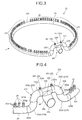
- FIG. 1 is a schematic view of a steam generator according to the embodiment.
- FIG. 2 is a cross sectional view of a water supply tube for a steam generator according to the embodiment.
- FIG. 3 is a perspective view illustrating the water supply tube for a steam generator according to the embodiment.
- FIG. 4 is a perspective view illustrating an essential portion of the water supply tube for a steam generator according to the embodiment. Note that, FIG. 2 illustrates a cross section of the water supply tube for a steam generator viewed along the horizontal direction as shown in the arrow I in FIG. 3 .
- the steam generator 1 is used for, for example, the PWR (Pressurized Water Reactor).
- Light water is used as a nuclear reactor coolant and a neutron moderator in the pressurized water reactor.
- the steam generator 1 transfers the heat of the high-temperature and high-pressure primary cooling water to secondary cooling water to generate steam in the secondary cooling water. With this steam, a turbine generator is rotated to produce power.
- the steam generator 1 extends in the up-and-down direction to form a sealed hollow cylindrical shape.
- the steam generator 1 includes a body portion 2 having an upper half portion and a lower half portion of which diameter is slightly smaller than that of the upper half portion.
- the body portion 2 is a shell member of the steam generator 1.
- a tube bundle shroud 3 formed in a cylindrical shape is provided so as to be arranged with a predetermined gap against the inner wall surface of the body portion 2.
- the tube bundle shroud 3 extends downward so that the bottom end portion of the tube bundle shroud 3 is located just above the tube plate 4 arranged in the lower part of the lower half portion of the body portion 2.
- a heat exchange tube bundle 51 composed of a plurality of heat exchange tubes 5 each formed in an inverted U-shape is provided in the tube bundle shroud 3.
- Each heat exchanger tube 5 is arranged so as the U-shaped arc portion to be in the upper side.
- the end portion in the bottom side of each heat exchanger tube 5 is supported by the tube plate 4 and the middle portion of each heat exchanger tube 5 is supported by a plurality of tube supporting plates 6.
- a large number of penetration holes (not shown in the drawing), in each of which the heat exchanger tube 5 is inserted to be supported, are formed.
- a channel head 7 is provided in the bottom end portion of the body portion 2.
- a partition wall 8 divides the inside of the channel head 7 into an inlet chamber 71 and an outlet chamber 72.
- One of ends of each heat exchanger tube 5 is connected to the inlet chamber 71 and the other end of each heat exchanger tube 5 is connected to the outlet chamber 72.
- the inlet chamber 71 has an inlet nozzle 711 communicating with the outside of the body portion 2.
- the outlet chamber 72 has an outlet nozzle 721 communicating with the outside of the body portion 2.
- a cooling water pipe (not shown in the drawing) through which the primary cooling water is supplied from the pressurized water reactor is connected to the inlet nozzle 711.
- a cooling water pipe (not shown in the drawing) through which the primary cooling water, after exchanging heat, is supplied to the pressurized water reactor is connected to the outlet nozzle 721.
- a steam-water separator 9 which separates the steam flow into steam and hot water and a moisture separator 10 which removes moisture from the separated steam to provide a steam condition close to the dry steam.
- a water supply tube for a steam generator for supplying a secondary cooling water into the body portion 2 from outside hereinafter simply referred to as a "water supply tube" 20 is inserted.
- a steam discharge port 12 is formed on the top end portion of the body portion 2.
- a water supply passage 13 which allows the secondary cooling water supplied from the water supply tube 20 into the body portion 2 to fall through the gap between the body portion 2 and the tube bundle shroud 3, make turn at the tube plate 4, and ascend along the heat exchange tube bundle 51.
- a steam supply passage (not shown in the drawing) for supplying steam to the turbine is connected to the steam discharge port 12.
- the primary cooling water heated in the pressurized water reactor is transferred to the inlet chamber 71 and finally to the outlet chamber 72 by passing through a large number of heat exchange tubes 5.
- the secondary cooling water cooled by the steam condenser is transferred to the water supply tube 20, and then supplied into the body portion 2 via the water supply tube 20.
- the secondary cooling water may be simply referred to as "cooling water.”
- the cooling water supplied to the body portion 2 ascends along the heat exchange tube bundle 51, passing through the water supply passage 13. In this step, heat is exchanged between the high-pressure and high-temperature primary cooling water and the secondary cooling water. Then, the cooled primary cooling water returns to the pressurized water reactor through the outlet chamber 72.
- the secondary cooling water which exchanged heat with the high-pressure and high-temperature primary cooling water ascends in the body portion 2 and is separated into steam and hot water in the steam-water separator 9. Then, the moisture is removed in the moisture separator 10 and the separated steam is transferred to the turbine.
- the water supply tube 20 includes a tubular passage in which the cooling water supplied from outside the steam generator 1 flows and an effluence tube 25 which allows effluence of the cooling water in the tubular passage to a space 40 in the steam generator 1 (see FIG. 2 to FIG. 4 ).
- the water supply tube 20 is arranged so as to allow effluence of the cooling water below the water level of the cooling water in the space 40 during the operation of the steam generator 1.
- thermal stratification between the cooling water with low temperature and the cooling water with high temperature may occur inside the tube, or thermal stratification between steam and cooling water may occur.
- thermal stratification is generated in the tube, stress causing fatigue is generated, which is not preferable.
- thermal stratification in the water supply tube 20 can be suppressed.
- thermal stratification can be suppressed in the portion of the water supply tube 20 which is inserted in a penetration hole penetrating the body portion 2.
- a generator internal tube portion 22 of the water supply tube 20 of the embodiment is arranged inside the steam generator 1 and includes a connection tube portion 24 (e.g., see FIG. 2 ) bent to raise the downstream side from the insert tube portion 21 inserted in the penetration hole 112 penetrating the body portion 2 and a tilted tube portion 233 (e.g., see FIG. 2 ) bent to lower the further downstream side. Since the bent portion is provided to raise the downstream side, along the flow direction of the cooling water supplied from outside, from the insert tube portion 21, the cooling water passes through the insert tube portion 21 within a short period of time before developing thermal stratification so that generation of thermal stress in the body portion 2 is suppressed.
- a connection tube portion 24 e.g., see FIG. 2
- a tilted tube portion 233 e.g., see FIG. 2
- the degree of freedom of water supply tube 20 in designing arrangement regarding other structures in the steam generator 1 and the degree of freedom in designing elevation of the water level in the generator are provided.
- the water supply tube 20 includes the insert tube portion 21 and the generator internal tube portion 22. Both the insert tube portion 21 and the generator internal tube portion 22 are tubular members having a circular cross section. A tubular passage is formed along each axial direction of the insert tube portion 21 and the generator internal tube portion 22.
- the cooling water supplied from outside the steam generator 1 flows through the tubular passage of the generator internal tube portion 22 via the insert tube portion 21.
- the body portion 2 includes a nozzle 11.
- the nozzle 11 includes a protrusion 111 protruding toward the radially outward direction of the body portion 2.
- a penetration hole 112 penetrating the nozzle 11 along the axial direction of the protrusion 111 is formed.
- the insert tube portion 21 engages with the penetration hole 112 from the radially inner side of the body portion 2.
- the insert tube portion 21 is secured to the nozzle 11 by welding or the like so that the outer circumferential surface of the insert tube portion 21 and the inner circumferential surface of the protrusion 111 face each other. That is, the insert tube portion 21 is inserted in the penetration hole 112 penetrating the body portion 2 of the steam generator 1.
- the central axis of the nozzle 11, that is, the central axis of the penetration hole 112 is horizontally provided and correspondingly, the insert tube portion 21 extends in the horizontal direction. Further, the insert tube portion 21 linearly extends along the radial direction of the body portion 2.
- the generator internal tube portion 22 is arranged inside the body portion 2, that is, inside the steam generator 1. As illustrated in FIG. 2 and FIG. 3 , the generator internal tube portion 22 includes a ring tube portion 23 extending in a ring shape and a connection tube portion 24 branching off from the ring tube portion 23 to connect the ring tube portion 23 and the insert tube portion 21.
- the ring tube portion 23 extends along the circumferential direction of the body portion 2, routing along the inner wall surface 2a of the body portion 2 illustrated in FIG. 2 .
- the ring tube portion 23 is arranged on the same axis as the central axis 50 of the body portion 2.
- the ring tube portion 23 is supported on the inner wall surface 2a of the body portion 2 via a stay 14.
- the ring tube portion 23 includes a horizontal ring tube portion 231 and an upper ring tube portion 232 raised vertically higher than the horizontal ring tube portion 231.
- the horizontal ring tube portion 231 extends in the horizontal direction.
- the tubular passage formed in the horizontal ring tube portion 231 along the axial direction that is, a horizontal ring tubular passage 231a also extends in the horizontal direction. That is, the top end 231b in any of cross sections, perpendicular to the flow direction of the cooling water, of the horizontal ring tubular passage 231a has the same vertical location. Further, the bottom end 231c in any of cross sections, perpendicular to the flow direction of the cooling water, of the horizontal ring tubular passage 231a has the same vertical location.
- the central axis of the horizontal ring tubular passage 231a extends on the same horizontal plane and the horizontal ring tubular passage 231a has a constant diameter.
- the horizontal ring tube portion 231 in which the horizontal ring tubular passage 231a is formed is arranged farther than the tilted tube portion 233, along the flow direction of the cooling water, from the insert tube portion 21. That is, the horizontal ring tubular passage 231a is arranged in the downstream side, in the flow direction of the cooling water supplied from outside the steam generator 1, than the tubular passage 233e of the tilted tube portion 233.
- the upper ring tube portion 232 includes two tilted tube portions 233 and an upper horizontal tube portion 234.
- the tilted tube portion 233 is connected to the insert tube portion 21 via the upper horizontal tube portion 234 and the connection tube portion 24. That is, the tilted tube portion 233 is located with the longer distance, along the flow direction of the cooling water in the generator internal tube portion 22, from the insert tube portion 21 than the connection tube portion 24. In other words, the distance of the flow passage from the insert tube portion 21 to the tilted tube portion 233 is longer than the distance of the flow passage from the insert tube portion 21 to the connection tube portion 24.
- the upper horizontal tube portion 234 is a linear tube portion extending in the horizontal direction.
- the connection tube portion 24 branches off from the upper horizontal tube portion 234.
- the connection tube portion 24 branches off from the bottom portion of the upper horizontal tube portion 234 toward the outer side along the radial direction of the body portion 2.
- the end portion, in the side opposite to the side connected to the upper horizontal tube portion 234, of the connection tube portion 24 is connected to the insert tube portion 21. That is, the connection tube portion 24 branches off from the ring tube portion 23 to connect the ring tube portion 23 and the insert tube portion 21.
- the connection tube portion 24 is tilted so that the side having the greater distance from the insert tube portion 21 along the flow direction of the cooling water is located vertically higher than the side having the smaller distance from the insert tube portion 21.
- connection tube portion 24 is tilted so that the end portion 24b side connected to the upper horizontal tube portion 234 is located vertically higher than the end portion 24a side connected to the insert tube portion 21. Accordingly, the tubular passage 24c formed in the connection tube portion 24 is tilted so that the side having the greater distance from the insert tube portion 21 along the flow direction of the cooling water is located vertically higher than the side having the smaller distance from the insert tube portion 21.
- the tubular passage 24c formed in the connection tube portion 24 corresponds to a first tilted portion.
- the gradient of the flow passage is greater at a location with a greater distance from the insert tube portion 21 than a location with a smaller distance from the insert tube portion 21.
- the tilted tube portions 233 are formed on respective both sides, in the axial direction, of the ring tube portion 23 with the connection tube portion 24 in between.
- One of tilted tube portions 233 connects one of ends of the upper horizontal tube portion 234 and one of ends of the horizontal ring tube portion 231.
- the other of tilted tube portions 233 connects the other end of the upper horizontal tube portion 234 and the other end of the horizontal ring tube portion 231.
- the tilted tube portion 233 is tilted so that the side having the greater distance from the insert tube portion 21 along the flow direction of the cooling water is located vertically lower than the side having the smaller distance from the insert tube portion 21. That is, as illustrated in FIG.
- the tilted tube portion 233 is tilted so that the side with the end portion 233b connected to the horizontal ring tube portion 231 is located vertically lower than the side with the end portion 233a connected to the upper horizontal tube portion 234. Accordingly, the tubular passage 233e formed in the tilted tube portion 233 is tilted so that the side having the greater distance from the insert tube portion 21 along the flow direction of the cooling water is located vertically lower than the side having the smaller distance from the insert tube portion 21.
- the tubular passage 233e corresponds to a second tilted portion.
- the tilted tube portion 233 of the embodiment includes two elbow parts 233c and 233d which are connected in serial.
- One of the elbow parts, that is, 233c extends toward the vertically higher side from a connection 233g between two elbows and is bent toward one of the sides along the circumferential direction.
- the other elbow part, that is, 233d extends toward the vertically lower side from the connection 233g and is bent toward the other side along the circumferential direction. In this manner, the tilted tube portion 233 is bent downward from the upper horizontal tube portion 234 to be connected to the horizontal ring tube portion 231. Further, as illustrated in FIG.
- the tilted tube portion 233 is tilted so that the vertically lower side of the tilted tube portion 233 is located in radially outer side of the body portion 2 than the vertically higher side of the tilted tube portion 233. That is, the vertically lower side of the tilted tube portion 233 is closer to the inner wall surface 2a of the body portion 2 than the vertically higher side of the tilted tube portion 233. Arranged in this manner, even when any other structure is arranged in the radially inner region of the body portion 2, the ring tube portion 23 can be arranged without interfering with the other structure.
- the tilt in the radial direction of the tilted tube portion 233 is not limited to the configuration described above.
- the tilt of the tilted tube portion 233 may suitably be determined in any direction as long as the interference between other structures and the ring tube portion 23 can be avoided.
- the first tilted portion which is an upward-bent portion of the tubular passage
- the second tilted portion which is a downward-bent portion of the tubular passage
- the ring tube portion 23 is formed in the circumferential direction, branching from both sides of the connection tube portion 24.
- connection tube portion 24 If both the first tilted portion, which is the upward-bent portion, and the second tilted portion, which is the downward-bent portion, are to be formed in the connection tube portion 24, that is, at a location upstream of the location from which the ring tube portion 23 branches, a large space is necessary. If both the first tilted portion and the second tilted portion are to be formed in the connection tube portion 24, the connection tube portion 24 needs to be bent in a U-shape or a V-shape, resulting in the connection tube portion 24 greatly protruding along the radial direction toward the center of the body portion 2. As a result, the connection tube portion 24 is likely to interfere with other structures.
- the tubular passage 233e as the second tilted portion in the ring tube portion 23 branching from the connection tube portion 24, the space for forming the second tilted portion is easily provided.
- the second tilted portion can extend along the circumferential direction. That is, the second tilted portion can be formed avoiding interference with the structure arranged in the central side along the radial direction of the body portion 2. Therefore, the degree of freedom of arranging the second tilted portion is large.
- the interference with other structures can be avoided by providing a tilt to the tilted tube portion 233 so that the vertically lower side of the tilted tube portion 233 is arranged in the radially outer side of the body portion 2 than the vertically higher side of the tilted tube portion 233.
- a constant tube diameter (inner diameter) can be provided for each of the insert tube portion 21, the connection tube portion 24, and the ring tube portion 23.
- tube diameters of the insert tube portion 21 and the connection tube portion 24 are the same, and the tube diameter of the ring tube portion 23 is smaller than the tube diameter of the connection tube portion 24.
- the ring tube portion 23 includes an effluence tube 25.
- the effluence tube 25 functions as an effluence unit to allow effluence of cooling water, in the tubular passage formed in the ring tube portion 23, from the tubular passage to the space 40 in the steam generator 1.
- the effluence tube 25 is a hollow cylindrical member.
- a plurality of effluence tubes 25 is arranged on the ring tube portion 23 along the extending direction of the ring tube portion 23. As illustrated in FIG. 4 , a plurality of penetration holes 25a, penetrating the cylindrical portion of the effluence tube 25 in the radial direction, is provided in the cylindrical portion of the effluence tube 25.
- one of ends of the effluence tube 25 in the axial direction is connected to the tubular passage of the ring tube portion 23 via a flow hole, which is not illustrated in the drawing, formed in the ring tube portion 23.
- the flow hole is formed in the top portion of the ring tube portion 23. That is, the effluence tube 25 is connected to the upper end of the tubular passage, when viewed from the axial direction of the tubular passage, formed in the ring tube portion 23.
- the end portion in the vertically higher side of the effluence tube 25, that is, the end portion in the opposite side to the end portion connected to the ring tube portion 23 is closed.
- the cooling water When the cooling water is supplied to the ring tube portion 23 via the insert tube portion 21 from outside the steam generator 1, the cooling water flows into the effluence tube 25 from the tubular passage of the ring tube portion 23, and then effluence of the cooling water into the space 40 in the steam generator 1 is generated via the penetration hole 25a.
- a large number of penetration holes 25a are uniformly arranged in the circumferential direction and the axial direction in the effluence tube 25. Therefore, uniform effluence of the cooling water is generated around the effluence tube 25.
- the effluence tube 25 is not provided on the connection tube portion 24, that is, the section, in which the first tilted portion is formed, in the generator internal tube portion 22.
- the flow hole communicating between the tubular passage of the ring tube portion 23 and the effluence tube 25 are formed on the ridge of the ring tube portion 23, the decrease in the water level of the cooling water in the tubular passage of the ring tube portion 23 is suppressed, even when the water level of the cooling water in the steam generator 1 is low enough to expose the ring tube portion 23 above the water level. In this manner, the generation of a steam-pocket in the tubular passage of the ring tube portion 23 is suppressed.
- the bottom end 234b of the cross section of the tubular passage 234a formed in the upper horizontal tube portion 234 is located vertically higher than the top end 21a of the inner wall surface of the insert tube portion 21. In this manner, the generation of thermal stratification in the insert tube portion 21 is suppressed as will be described below.
- the bottom end 234b of the cross section, perpendicular to the flow direction of the cooling water, of the tubular passage 234a formed in the upper horizontal tube portion 234 is located vertically higher than the top end 21a of the inner wall surface of the insert tube portion 21 at the connection between the insert tube portion 21 and the connection tube portion 24.
- the cross section, perpendicular to the flow direction of the cooling water, of the tubular passage 234a does not intersect with a horizontal plane 30 including the top end 21a of the inner wall surface of the insert tube portion 21 at the connection between the insert tube portion 21 and the connection tube portion 24.
- the bottom end 234b of the cross section is located vertically higher than the horizontal plane 30.
- the decrease in the water level in the tube, which is in the insert tube portion 21 side from the upper horizontal tube portion 234, of the water supply tube 20 can be suppressed.
- the decrease in the water level of the cooling water is suppressed so that the water level will not to be lower than the bottom end 234b of the tubular passage 234a, thereby keeping the insert tube portion 21 filled with the cooling water.
- the connection tube portion 24 of the embodiment does not include the effluence tube 25. Therefore, the decrease in the water level of the cooling water is surely suppressed so that the water level will not be lower than the bottom end 234b of the tubular passage 234a.
- a certain period of time is necessary for the whole water supply tube to be filled with the cooling water after start supplying cooling water to the water supply tube containing a low level of water as in the start of the operation of steam generator 1.
- a water supply tube which includes the insert tube portion 21 and the ring tube portion 23 horizontally extending in the same height and does not have an upward-bent portion like the connection tube portion 24 or a downward-bent portion like the tilted tube portion 233.
- layers of steam and cooling water separately exist in the insert tube portion 21, with the generated stress remaining in the insert tube portion 21 causing fatigue.
- a water hammer may occur by the steam making contact with the cooling water. It is desirable to suppress these thermal stress and water hammer in the vicinity of the nozzle 11 provided as a boundary.
- the insert tube portion 21 when supplying of the cooling water to the water supply tube 20 containing a low level of water starts, first, the insert tube portion 21 is filled with the cooling water, and then after the rise in the water level, the cooling water is supplied from the connection tube portion 24 to the horizontal ring tube portion 231 via the upper ring tube portion 232. In this manner, the period of time in which the steam layer and the cooling water layer are generated in the insert tube portion 21 can be shortened, thereby suppressing generation of stress causing fatigue in the insert tube portion 21.
- the state in which layers of cooling water having different temperatures exist separately in the insert tube portion 21 can easily be avoided, as will be described below.
- thermal stratification is generated in which layers of low-temperature cooling water and high-temperature cooling water separately exist.
- the thermal stratification thus generated is likely to remain longer in the insert tube portion 21 of the water supply tube including the insert tube portion 21 and the ring tube portion 23 horizontally extending in the same height.
- the insert tube portion 21 when low-temperature cooling water is supplied, with a small flow rate, from outside the steam generator 1 into the water supply tube 20 with high-temperature cooling water remaining therein, the insert tube portion 21 is rapidly filled with the cooling water supplied from outside, generating the effluence of the high-temperature cooling water in the insert tube portion 21 from the connection tube portion 24 to the upper ring tube portion 232 and the horizontal ring tube portion 231.
- the water supply tube 20 eliminates the thermal stratification in the insert tube portion 21 in a short period of time compared to the supply tube including the insert tube portion 21 and the ring tube portion 23 horizontally extending in the same height.
- the tubular passage 234a formed in the upper horizontal tube portion 234 corresponds to the tubular passage between the first tilted portion and the second tilted portion.
- the bottom end 234b of the cross section, perpendicular to the flow direction of the cooling water, of the entire section of the tubular passage 234a is arranged vertically higher than the horizontal plane 30.
- the present invention is not limited to the configuration. Any configuration is allowed as long as the bottom end 234b of the cross section, perpendicular to the flow direction of the cooling water, of the tubular passage 234a is arranged vertically higher than the horizontal plane 30 in at least a portion of the section, along the flow direction, of the tubular passage 234a.
- FIG. 5 is a cross sectional view illustrating an example of the water supply tube capable of suppressing thermal stratification in an insert tube portion.
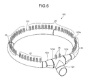
- FIG. 6 is a perspective view illustrating an example of the water supply tube capable of suppressing thermal stratification in an insert tube portion.
- the ring tube portion 123 of the water supply tube 120 does not include the tilted tube portion 233 as in the embodiment. As illustrated in FIG.
- the vertical location of the top end 123b of the cross section perpendicular to the flow direction of the cooling water is the same at any location in the flow direction of the cooling water. That is, at any location in the flow direction of the cooling water, the top end 123b of the cross section, perpendicular to the flow direction of the cooling water, of the tubular passage 123a is on the same horizontal plane.
- the ring tube portion 123 includes a tapered portion 123c.
- the tapered portion 123c is formed in the vicinity of the connection between the ring tube portion 123 and the connection tube portion 124.
- the tapered portion 123c is formed on both sides, in the circumferential direction, of the connection between the ring tube portion 123 and the connection tube portion 124.
- the tapered portion 123c has a tapered shape in which the diameter is smaller for a location farther from the connection tube portion 124 along the flow direction of the cooling water in the ring tube portion 123. In the tapered portion 123c, the flow area of the tubular passage 123a gradually decreases as the cross section is distanced from the connection tube portion 124.
- the diameter of the ring-side connection tube portion 123d which is arranged closer to the connection tube portion 124 than the tapered portion 123c, is larger than the diameter of the portion 123e which is arranged farther from the connection tube portion 124 than the tapered portion 123c.
- the connection tube portion 124 is similar to the connection tube portion 24 of the water supply tube 20 and is tilted so that the side having the greater distance from the insert tube portion 21 along the flow direction of the cooling water is located vertically higher than the side having the smaller distance from the insert tube portion 21.
- the ring-side connection tube portion 123d is a linear tubular portion having a constant diameter. As illustrated in FIG. 5 , the bottom end 123f of the cross section, perpendicular to the flow direction of the cooling water, of the ring-side connection tube portion 123d is located vertically higher than the top end 21a of the inner wall surface of the insert tube portion 21 at the connection between the insert tube portion 21 and the connection tube portion 124.
- the water supply tube 120 can also suppress the generation of thermal stratification in the insert tube portion 21 or rapidly eliminate the thermal stratification, thereby suppressing generation of thermal stress causing fatigue.
- the ring tube portion 123 is easily exposed to a gas layer when the water level in the steam generator 1 decreases.
- the generator internal tube portion 22 is bent to raise itself against the insert tube portion 21 at the connection tube portion 24, and then bent to lower itself at the tilted tube portion 233. In this manner, the vertical location of the horizontal ring tube portion 231 is lowered, thereby suppressing exposure of the horizontal ring tube portion 231 above the surface of the cooling water. As illustrated in FIG. 3 and FIG. 4 , in the water supply tube 20 of the embodiment, the generator internal tube portion 22 is bent to raise itself against the insert tube portion 21 at the connection tube portion 24, and then bent to lower itself at the tilted tube portion 233. In this manner, the vertical location of the horizontal ring tube portion 231 is lowered, thereby suppressing exposure of the horizontal ring tube portion 231 above the surface of the cooling water. As illustrated in FIG.
- the top end 231b of the cross section, perpendicular to the flow direction of the cooling water, of the tubular passage 231a in the horizontal ring tube portion 231 is located vertically lower than the horizontal plane 30 including the top end 21a of the inner wall surface of the insert tube portion 21 at the connection between the insert tube portion 21 and the connection tube portion 24.
- the tubular passage 231a in the horizontal ring tube portion 231 is kept below the water level even when the cooling water level in the steam generator 1 is low enough to start exposing the insert tube portion 21.
- the vertical location of the tubular passage 231a formed in the horizontal ring tube portion 231 is not limited to the configuration described above. Any vertical location can be determined.
- the top end 231b of the cross section, perpendicular to the flow direction of the cooling water, of the tubular passage 231a is located vertically lower than the central axis X of the insert tube portion 21. Configured in such manner, in the water supply tube 20 of the embodiment, any vertical location of the tubular passage 231a in the horizontal ring tube portion 231 can be determined, maintaining the effect of suppressing thermal stratification in the insert tube portion 21.
- the upper horizontal tube portion 234 is provided with an effluence tube 251 (25).
- This configuration suppresses suction of the cooling water in the insert tube portion 21 out into the horizontal ring tube portion 231 side when the cooling water level in the steam generator 1 decreases.
- the cooling water in the insert tube portion 21 located higher than the horizontal ring tube portion 231 may be suctioned out into the horizontal ring tube portion 231 side.
- the effluence tube 251 provided on the upper horizontal tube portion 234 is exposed when the cooling water level in the steam generator 1 decreases, thereby opening the tubular passage 234a. In this manner, the suction of the cooling water in the insert tube portion 21 out into the horizontal ring tube portion 231 is suppressed.
- the vertical location of the horizontal ring tube portion 231 can be determined based on the predetermined target for controlling the water level of the cooling water in the space 40 in the steam generator 1.
- the target water level of the cooling water is determined depending on a control parameter of a nuclear plant including the steam generator 1.
- a lower limit is determined for the target of the water level to be controlled, it may be configured that the top end 231b of the cross section, perpendicular to the flow direction of the cooling water, of the tubular passage 231a is located vertically lower than the lower limit of the water level. Configured in this manner, as long as the cooling water level in the steam generator 1 is at, or higher than, the lower limit of the target water level, the tubular passage 231a is kept below the surface of the cooling water. Thereby, the generation of a steam-pocket in the tubular passage 231a is suppressed.
- the vertical location of the horizontal ring tube portion 231 may be determined so that, for example, the tubular passage 231a in the horizontal ring tube portion 231 is located below the cooling water level in the space 40 in the steam generator 1 even when a supplied flow rate of low-temperature cooling water is small, as in the start-up or shutdown under a hot state in a plant.
- the tube portion including the effluence tube 25 is provided as the ring tube portion 23 extending in a ring shape.
- the shape of the tube portion including the effluence tube 25 is not limited to such configuration.
Landscapes
- Engineering & Computer Science (AREA)
- Physics & Mathematics (AREA)
- Thermal Sciences (AREA)
- Mechanical Engineering (AREA)
- General Engineering & Computer Science (AREA)
- Life Sciences & Earth Sciences (AREA)
- Sustainable Development (AREA)
- Sustainable Energy (AREA)
- Heat-Exchange Devices With Radiators And Conduit Assemblies (AREA)
- Pipeline Systems (AREA)
Abstract
Description
- The present invention relates to a water supply tube for a steam generator.
- Conventionally, a water supply tube for supplying cooling water into a steam generator of a pressurized water reactor or the like is known. When steam or high-temperature water in a generator flows into a water supply tube or such similar state happens, thermal stratification may occur in the water supply tube. Thermal stratification might generate stress causing fatigue and therefore is not preferable.
- In Patent Literature 1, a technique applied to a water supply tube for a steam generator is disclosed, in which a dam is attached to an inner upper wall of the water supply tube bent to raise a water supply ring.
- Patent Literature 1: Japanese Utility Model Laid-open No.
61-121304 - Further consideration can be made to prevent thermal stratification in a water supply tube. The object of the present invention is to provide a water supply tube for a steam generator capable of suppressing thermal stratification in the tube.
- According to an aspect of the present invention, a water supply tube for a steam generator includes: an insert tube portion horizontally extending and configured to be inserted in a penetration hole penetrating a shell member of the steam generator; and a generator internal tube portion connected to the insert tube portion and arranged inside the steam generator. The generator internal tube portion includes a tubular passage formed in an axial direction of the generator internal tube portion and an effluence unit allowing effluence of cooling water in the tubular passage from the tubular passage to a space in the steam generator, the tubular passage allowing cooling water supplied from outside the steam generator via the insert tube portion to flow in the tubular passage. The tubular passage includes a first tilted portion which is tilted so that a side having a greater distance from the insert tube portion along a flow direction of cooling water is located vertically higher than a side having a smaller distance from the insert tube portion and a second tilted portion which is located with a greater distance from the insert tube portion along the flow direction than the first tilted portion and is tilted so that a side having a greater distance from the insert tube portion along the flow direction is located vertically lower than a side having a smaller distance from the insert tube portion. In at least a portion of a section, along the flow direction, of the tubular passage between the first tilted portion and the second tilted portion, a bottom end of a cross section, perpendicular to the flow direction, of the tubular passage is arranged vertically higher than a horizontal plane including a top end of an inner wall surface of the insert tube portion at a connection between the insert tube portion and the generator internal tube portion.
- According to the water supply tube for a steam generator, thermal stratification caused by a steam-pocket generated in an insert tube portion can be suppressed by suppressing the decrease in water level in the insert tube portion. Further, in a case when the cooling water having different temperature from the cooling water in the insert tube portion flows in, the effluence of the cooling water having high temperature to the generator internal tube portion is generated to suppress the thermal stratification.
- Advantageously, in the water supply tube for a steam generator, the effluence unit is not included in a section, of the generator internal tube portion, in which the first tilted portion is formed.
- According to the water supply tube for a steam generator, the decrease in water level in the insert tube portion can be suppressed even when the cooling water level in the steam generator decreases.
- Advantageously, in the water supply tube for a steam generator, the generator internal tube portion includes a ring tube portion extending in a ring shape along an inner circumferential surface of the shell member and a connection tube portion branching off from the ring tube portion to connect the ring tube portion and the insert tube portion. The first tilted portion is provided as the tubular passage formed in the connection tube portion, and the second tilted portion is provided as the tubular passage formed in the ring tube portion, the second tilted portion being formed on each of both ends, in an axial direction, of the ring tube portion with the connection tube portion in between.
- According to the water supply tube for a steam generator, a first tilted portion and a second tilted portion can be formed by suppressing interference against other structures in the steam generator.
- Advantageously, in the water supply tube for a steam generator, a horizontal ring tubular passage which is the tubular passage extending in a horizontal direction is formed in a portion, arranged farther than the second tilted portion from the insert tube portion along the flow direction, of the ring tube portion, and a top end of a cross section, perpendicular to the flow direction, of the horizontal ring tubular passage is provided vertically lower than the horizontal plane including the top end of the inner wall surface of the insert tube portion at the connection between the insert tube portion and the generator internal tube portion.
- According to the water supply tube for a steam generator, when the cooling water level in the steam generator decreases, generation of a steam-pocket in a horizontal ring tubular passage is suppressed since exposure of a ring tube portion is suppressed.
- Advantageously, in the water supply tube for a steam generator, a horizontal ring tubular passage which is the tubular passage extending in a horizontal direction is formed in a portion, arranged farther than the second tilted portion from the insert tube portion along the flow direction, of the ring tube portion, and a top end of a cross section, perpendicular to the flow direction, of the horizontal ring tubular passage is arranged vertically lower than a lower limit of a target for controlling a water level of cooling water in the space in the steam generator.
- According to the water supply tube for a steam generator, even when the cooling water level in the steam generator decreases to a lower limit of the target for controlling the water level, generation of a steam-pocket in the horizontal ring tubular passage is suppressed. Advantageous Effects of Invention
- According to the present invention, the thermal stratification in a water supply tube for a steam generator can be suppressed.
-
-
FIG. 1 is a schematic view of a steam generator according to an embodiment. -
FIG. 2 is a cross sectional view of the water supply tube for a steam generator according to the embodiment. -
FIG. 3 is a perspective view illustrating the water supply tube for a steam generator according to the embodiment. -
FIG. 4 is a perspective view illustrating an essential portion of the water supply tube for a steam generator according to the embodiment. -
FIG. 5 is a cross sectional view illustrating an example of the water supply tube capable of suppressing thermal stratification in an insert tube portion. -
FIG. 6 is a perspective view illustrating an example of the water supply tube capable of suppressing thermal stratification in the insert tube portion. - A water supply tube for a steam generator according to an embodiment of the present invention will be described below in detail referring to the drawings. The present invention is not limited to the embodiment. The component of the embodiment described below includes such component which can easily be conceived by those skilled in the art, or components substantially the same.
- The embodiment will be described referring to
FIG. 1 to FIG. 6 . The embodiment relates to a water supply tube for a steam generator.FIG. 1 is a schematic view of a steam generator according to the embodiment.FIG. 2 is a cross sectional view of a water supply tube for a steam generator according to the embodiment.FIG. 3 is a perspective view illustrating the water supply tube for a steam generator according to the embodiment.FIG. 4 is a perspective view illustrating an essential portion of the water supply tube for a steam generator according to the embodiment. Note that,FIG. 2 illustrates a cross section of the water supply tube for a steam generator viewed along the horizontal direction as shown in the arrow I inFIG. 3 . - The steam generator 1 is used for, for example, the PWR (Pressurized Water Reactor). Light water is used as a nuclear reactor coolant and a neutron moderator in the pressurized water reactor. In the pressurized water reactor, light water with high temperature and high pressure, which does not boil throughout the reactor internal, is supplied to the steam generator 1 as primary cooling water. The steam generator 1 transfers the heat of the high-temperature and high-pressure primary cooling water to secondary cooling water to generate steam in the secondary cooling water. With this steam, a turbine generator is rotated to produce power.
- The steam generator 1 extends in the up-and-down direction to form a sealed hollow cylindrical shape. The steam generator 1 includes a
body portion 2 having an upper half portion and a lower half portion of which diameter is slightly smaller than that of the upper half portion. Thebody portion 2 is a shell member of the steam generator 1. In the lower half portion of thebody portion 2, atube bundle shroud 3 formed in a cylindrical shape is provided so as to be arranged with a predetermined gap against the inner wall surface of thebody portion 2. Thetube bundle shroud 3 extends downward so that the bottom end portion of thetube bundle shroud 3 is located just above thetube plate 4 arranged in the lower part of the lower half portion of thebody portion 2. A heatexchange tube bundle 51 composed of a plurality ofheat exchange tubes 5 each formed in an inverted U-shape is provided in thetube bundle shroud 3. Eachheat exchanger tube 5 is arranged so as the U-shaped arc portion to be in the upper side. The end portion in the bottom side of eachheat exchanger tube 5 is supported by thetube plate 4 and the middle portion of eachheat exchanger tube 5 is supported by a plurality oftube supporting plates 6. In thetube supporting plate 6, a large number of penetration holes (not shown in the drawing), in each of which theheat exchanger tube 5 is inserted to be supported, are formed. - In the bottom end portion of the
body portion 2, achannel head 7 is provided. Apartition wall 8 divides the inside of thechannel head 7 into aninlet chamber 71 and anoutlet chamber 72. One of ends of eachheat exchanger tube 5 is connected to theinlet chamber 71 and the other end of eachheat exchanger tube 5 is connected to theoutlet chamber 72. Theinlet chamber 71 has aninlet nozzle 711 communicating with the outside of thebody portion 2. Theoutlet chamber 72 has anoutlet nozzle 721 communicating with the outside of thebody portion 2. A cooling water pipe (not shown in the drawing) through which the primary cooling water is supplied from the pressurized water reactor is connected to theinlet nozzle 711. A cooling water pipe (not shown in the drawing) through which the primary cooling water, after exchanging heat, is supplied to the pressurized water reactor is connected to theoutlet nozzle 721. - Provided in the upper half portion of the
body portion 2 are a steam-water separator 9 which separates the steam flow into steam and hot water and amoisture separator 10 which removes moisture from the separated steam to provide a steam condition close to the dry steam. Between the steam-water separator 9 and the heatexchange tube bundle 51, a water supply tube for a steam generator for supplying a secondary cooling water into thebody portion 2 from outside (hereinafter simply referred to as a "water supply tube") 20 is inserted. Asteam discharge port 12 is formed on the top end portion of thebody portion 2. Provided in the lower half portion of thebody portion 2 is awater supply passage 13 which allows the secondary cooling water supplied from thewater supply tube 20 into thebody portion 2 to fall through the gap between thebody portion 2 and thetube bundle shroud 3, make turn at thetube plate 4, and ascend along the heatexchange tube bundle 51. Note that, a steam supply passage (not shown in the drawing) for supplying steam to the turbine is connected to thesteam discharge port 12. A cooling water pipe (not shown in the drawing) for supplying the secondary cooling water recovered in a steam condenser (not shown in the drawing), by cooling the steam used in the turbine, is connected to thewater supply tube 20. - In the steam generator 1 as described above, the primary cooling water heated in the pressurized water reactor is transferred to the
inlet chamber 71 and finally to theoutlet chamber 72 by passing through a large number ofheat exchange tubes 5. Further, the secondary cooling water cooled by the steam condenser is transferred to thewater supply tube 20, and then supplied into thebody portion 2 via thewater supply tube 20. In the embodiment, the secondary cooling water may be simply referred to as "cooling water." The cooling water supplied to thebody portion 2 ascends along the heatexchange tube bundle 51, passing through thewater supply passage 13. In this step, heat is exchanged between the high-pressure and high-temperature primary cooling water and the secondary cooling water. Then, the cooled primary cooling water returns to the pressurized water reactor through theoutlet chamber 72. Further, the secondary cooling water which exchanged heat with the high-pressure and high-temperature primary cooling water ascends in thebody portion 2 and is separated into steam and hot water in the steam-water separator 9. Then, the moisture is removed in themoisture separator 10 and the separated steam is transferred to the turbine. - The
water supply tube 20 includes a tubular passage in which the cooling water supplied from outside the steam generator 1 flows and aneffluence tube 25 which allows effluence of the cooling water in the tubular passage to aspace 40 in the steam generator 1 (seeFIG. 2 to FIG. 4 ). Thewater supply tube 20 is arranged so as to allow effluence of the cooling water below the water level of the cooling water in thespace 40 during the operation of the steam generator 1. When supplying of the cooling water from outside the steam generator 1 stops or starts, such as in a shutdown and a startup of a nuclear reactor plant, thermal stratification may occur in thewater supply tube 20. For example, when a cooling water with low temperature is supplied, with a small flow rate, to thewater supply tube 20 containing high-temperature cooling water or steam, thermal stratification between the cooling water with low temperature and the cooling water with high temperature may occur inside the tube, or thermal stratification between steam and cooling water may occur. When thermal stratification is generated in the tube, stress causing fatigue is generated, which is not preferable. It is preferable if thermal stratification in thewater supply tube 20 can be suppressed. Particularly, it is preferable if thermal stratification can be suppressed in the portion of thewater supply tube 20 which is inserted in a penetration hole penetrating thebody portion 2. - In the steam generator 1, as will be described referring to
FIG. 2 to FIG. 4 , a generatorinternal tube portion 22 of thewater supply tube 20 of the embodiment is arranged inside the steam generator 1 and includes a connection tube portion 24 (e.g., seeFIG. 2 ) bent to raise the downstream side from theinsert tube portion 21 inserted in thepenetration hole 112 penetrating thebody portion 2 and a tilted tube portion 233 (e.g., seeFIG. 2 ) bent to lower the further downstream side. Since the bent portion is provided to raise the downstream side, along the flow direction of the cooling water supplied from outside, from theinsert tube portion 21, the cooling water passes through theinsert tube portion 21 within a short period of time before developing thermal stratification so that generation of thermal stress in thebody portion 2 is suppressed. Further, since thewater supply tube 20 which is first bent to raise the downstream side is then bent to lower the further downstream side, the degree of freedom ofwater supply tube 20 in designing arrangement regarding other structures in the steam generator 1 and the degree of freedom in designing elevation of the water level in the generator are provided. - As illustrated in
FIG. 2 , thewater supply tube 20 includes theinsert tube portion 21 and the generatorinternal tube portion 22. Both theinsert tube portion 21 and the generatorinternal tube portion 22 are tubular members having a circular cross section. A tubular passage is formed along each axial direction of theinsert tube portion 21 and the generatorinternal tube portion 22. The cooling water supplied from outside the steam generator 1 flows through the tubular passage of the generatorinternal tube portion 22 via theinsert tube portion 21. The effluence of the cooling water flowing through the tubular passage of the generatorinternal tube portion 22 from the tubular passage of the generatorinternal tube portion 22 to thespace 40 in the steam generator 1 via aneffluence tube 25, which will be described below, is generated. - The
body portion 2 includes anozzle 11. Thenozzle 11 includes aprotrusion 111 protruding toward the radially outward direction of thebody portion 2. In thenozzle 11, apenetration hole 112 penetrating thenozzle 11 along the axial direction of theprotrusion 111 is formed. Theinsert tube portion 21 engages with thepenetration hole 112 from the radially inner side of thebody portion 2. Theinsert tube portion 21 is secured to thenozzle 11 by welding or the like so that the outer circumferential surface of theinsert tube portion 21 and the inner circumferential surface of theprotrusion 111 face each other. That is, theinsert tube portion 21 is inserted in thepenetration hole 112 penetrating thebody portion 2 of the steam generator 1. The central axis of thenozzle 11, that is, the central axis of thepenetration hole 112 is horizontally provided and correspondingly, theinsert tube portion 21 extends in the horizontal direction. Further, theinsert tube portion 21 linearly extends along the radial direction of thebody portion 2. - The generator
internal tube portion 22 is arranged inside thebody portion 2, that is, inside the steam generator 1. As illustrated inFIG. 2 andFIG. 3 , the generatorinternal tube portion 22 includes aring tube portion 23 extending in a ring shape and aconnection tube portion 24 branching off from thering tube portion 23 to connect thering tube portion 23 and theinsert tube portion 21. Thering tube portion 23 extends along the circumferential direction of thebody portion 2, routing along theinner wall surface 2a of thebody portion 2 illustrated inFIG. 2 . For example, thering tube portion 23 is arranged on the same axis as thecentral axis 50 of thebody portion 2. As illustrated inFIG. 2 , thering tube portion 23 is supported on theinner wall surface 2a of thebody portion 2 via astay 14. Thering tube portion 23 includes a horizontalring tube portion 231 and an upperring tube portion 232 raised vertically higher than the horizontalring tube portion 231. - The horizontal
ring tube portion 231 extends in the horizontal direction. As illustrated inFIG. 2 , the tubular passage formed in the horizontalring tube portion 231 along the axial direction, that is, a horizontalring tubular passage 231a also extends in the horizontal direction. That is, thetop end 231b in any of cross sections, perpendicular to the flow direction of the cooling water, of the horizontalring tubular passage 231a has the same vertical location. Further, thebottom end 231c in any of cross sections, perpendicular to the flow direction of the cooling water, of the horizontalring tubular passage 231a has the same vertical location. In other words, the central axis of the horizontalring tubular passage 231a extends on the same horizontal plane and the horizontalring tubular passage 231a has a constant diameter. In thering tube portion 23, the horizontalring tube portion 231 in which the horizontalring tubular passage 231a is formed is arranged farther than the tiltedtube portion 233, along the flow direction of the cooling water, from theinsert tube portion 21. That is, the horizontalring tubular passage 231a is arranged in the downstream side, in the flow direction of the cooling water supplied from outside the steam generator 1, than thetubular passage 233e of the tiltedtube portion 233. - As illustrated in
FIG. 3 , the upperring tube portion 232 includes two tiltedtube portions 233 and an upperhorizontal tube portion 234. The tiltedtube portion 233 is connected to theinsert tube portion 21 via the upperhorizontal tube portion 234 and theconnection tube portion 24. That is, the tiltedtube portion 233 is located with the longer distance, along the flow direction of the cooling water in the generatorinternal tube portion 22, from theinsert tube portion 21 than theconnection tube portion 24. In other words, the distance of the flow passage from theinsert tube portion 21 to the tiltedtube portion 233 is longer than the distance of the flow passage from theinsert tube portion 21 to theconnection tube portion 24. - The upper
horizontal tube portion 234 is a linear tube portion extending in the horizontal direction. Theconnection tube portion 24 branches off from the upperhorizontal tube portion 234. Theconnection tube portion 24 branches off from the bottom portion of the upperhorizontal tube portion 234 toward the outer side along the radial direction of thebody portion 2. The end portion, in the side opposite to the side connected to the upperhorizontal tube portion 234, of theconnection tube portion 24 is connected to theinsert tube portion 21. That is, theconnection tube portion 24 branches off from thering tube portion 23 to connect thering tube portion 23 and theinsert tube portion 21. Theconnection tube portion 24 is tilted so that the side having the greater distance from theinsert tube portion 21 along the flow direction of the cooling water is located vertically higher than the side having the smaller distance from theinsert tube portion 21. That is, theconnection tube portion 24 is tilted so that theend portion 24b side connected to the upperhorizontal tube portion 234 is located vertically higher than theend portion 24a side connected to theinsert tube portion 21. Accordingly, thetubular passage 24c formed in theconnection tube portion 24 is tilted so that the side having the greater distance from theinsert tube portion 21 along the flow direction of the cooling water is located vertically higher than the side having the smaller distance from theinsert tube portion 21. Thetubular passage 24c formed in theconnection tube portion 24 corresponds to a first tilted portion. As for thetubular passage 24c, the gradient of the flow passage is greater at a location with a greater distance from theinsert tube portion 21 than a location with a smaller distance from theinsert tube portion 21. - The tilted
tube portions 233 are formed on respective both sides, in the axial direction, of thering tube portion 23 with theconnection tube portion 24 in between. One of tiltedtube portions 233 connects one of ends of the upperhorizontal tube portion 234 and one of ends of the horizontalring tube portion 231. The other of tiltedtube portions 233 connects the other end of the upperhorizontal tube portion 234 and the other end of the horizontalring tube portion 231. The tiltedtube portion 233 is tilted so that the side having the greater distance from theinsert tube portion 21 along the flow direction of the cooling water is located vertically lower than the side having the smaller distance from theinsert tube portion 21. That is, as illustrated inFIG. 4 , the tiltedtube portion 233 is tilted so that the side with theend portion 233b connected to the horizontalring tube portion 231 is located vertically lower than the side with theend portion 233a connected to the upperhorizontal tube portion 234. Accordingly, thetubular passage 233e formed in the tiltedtube portion 233 is tilted so that the side having the greater distance from theinsert tube portion 21 along the flow direction of the cooling water is located vertically lower than the side having the smaller distance from theinsert tube portion 21. Thetubular passage 233e corresponds to a second tilted portion. - The tilted
tube portion 233 of the embodiment includes twoelbow parts connection 233g between two elbows and is bent toward one of the sides along the circumferential direction. The other elbow part, that is, 233d extends toward the vertically lower side from theconnection 233g and is bent toward the other side along the circumferential direction. In this manner, the tiltedtube portion 233 is bent downward from the upperhorizontal tube portion 234 to be connected to the horizontalring tube portion 231. Further, as illustrated inFIG. 2 , the tiltedtube portion 233 is tilted so that the vertically lower side of the tiltedtube portion 233 is located in radially outer side of thebody portion 2 than the vertically higher side of the tiltedtube portion 233. That is, the vertically lower side of the tiltedtube portion 233 is closer to theinner wall surface 2a of thebody portion 2 than the vertically higher side of the tiltedtube portion 233. Arranged in this manner, even when any other structure is arranged in the radially inner region of thebody portion 2, thering tube portion 23 can be arranged without interfering with the other structure. Note that, the tilt in the radial direction of the tiltedtube portion 233 is not limited to the configuration described above. The tilt of the tiltedtube portion 233 may suitably be determined in any direction as long as the interference between other structures and thering tube portion 23 can be avoided. - Further, since the first tilted portion, which is an upward-bent portion of the tubular passage, is formed in the
connection tube portion 24 as thetubular passage 24c and the second tilted portion, which is a downward-bent portion of the tubular passage, is formed in thering tube portion 23 as thetubular passage 233e, a large degree of freedom is provided to the arrangement of the upward-bent portion and the downward-bent portion of the tubular passage. In the generatorinternal tube portion 22 of the embodiment, thering tube portion 23 is formed in the circumferential direction, branching from both sides of theconnection tube portion 24. If both the first tilted portion, which is the upward-bent portion, and the second tilted portion, which is the downward-bent portion, are to be formed in theconnection tube portion 24, that is, at a location upstream of the location from which thering tube portion 23 branches, a large space is necessary. If both the first tilted portion and the second tilted portion are to be formed in theconnection tube portion 24, theconnection tube portion 24 needs to be bent in a U-shape or a V-shape, resulting in theconnection tube portion 24 greatly protruding along the radial direction toward the center of thebody portion 2. As a result, theconnection tube portion 24 is likely to interfere with other structures. - Contrarily, by forming the
tubular passage 233e as the second tilted portion in thering tube portion 23 branching from theconnection tube portion 24, the space for forming the second tilted portion is easily provided. According to the technique of forming the second tilted portion (tubular passage 233e) by tilting the portion of thering tube portion 23 as in the embodiment, the second tilted portion can extend along the circumferential direction. That is, the second tilted portion can be formed avoiding interference with the structure arranged in the central side along the radial direction of thebody portion 2. Therefore, the degree of freedom of arranging the second tilted portion is large. For example, as described above, the interference with other structures can be avoided by providing a tilt to the tiltedtube portion 233 so that the vertically lower side of the tiltedtube portion 233 is arranged in the radially outer side of thebody portion 2 than the vertically higher side of the tiltedtube portion 233. - A constant tube diameter (inner diameter) can be provided for each of the
insert tube portion 21, theconnection tube portion 24, and thering tube portion 23. In the embodiment, tube diameters of theinsert tube portion 21 and theconnection tube portion 24 are the same, and the tube diameter of thering tube portion 23 is smaller than the tube diameter of theconnection tube portion 24. - The
ring tube portion 23 includes aneffluence tube 25. Theeffluence tube 25 functions as an effluence unit to allow effluence of cooling water, in the tubular passage formed in thering tube portion 23, from the tubular passage to thespace 40 in the steam generator 1. Theeffluence tube 25 is a hollow cylindrical member. A plurality ofeffluence tubes 25 is arranged on thering tube portion 23 along the extending direction of thering tube portion 23. As illustrated inFIG. 4 , a plurality ofpenetration holes 25a, penetrating the cylindrical portion of theeffluence tube 25 in the radial direction, is provided in the cylindrical portion of theeffluence tube 25. Further, one of ends of theeffluence tube 25 in the axial direction is connected to the tubular passage of thering tube portion 23 via a flow hole, which is not illustrated in the drawing, formed in thering tube portion 23. The flow hole is formed in the top portion of thering tube portion 23. That is, theeffluence tube 25 is connected to the upper end of the tubular passage, when viewed from the axial direction of the tubular passage, formed in thering tube portion 23. The end portion in the vertically higher side of theeffluence tube 25, that is, the end portion in the opposite side to the end portion connected to thering tube portion 23 is closed. - When the cooling water is supplied to the
ring tube portion 23 via theinsert tube portion 21 from outside the steam generator 1, the cooling water flows into theeffluence tube 25 from the tubular passage of thering tube portion 23, and then effluence of the cooling water into thespace 40 in the steam generator 1 is generated via thepenetration hole 25a. A large number ofpenetration holes 25a are uniformly arranged in the circumferential direction and the axial direction in theeffluence tube 25. Therefore, uniform effluence of the cooling water is generated around theeffluence tube 25. Note that, theeffluence tube 25 is not provided on theconnection tube portion 24, that is, the section, in which the first tilted portion is formed, in the generatorinternal tube portion 22. - Since the flow hole communicating between the tubular passage of the
ring tube portion 23 and theeffluence tube 25 are formed on the ridge of thering tube portion 23, the decrease in the water level of the cooling water in the tubular passage of thering tube portion 23 is suppressed, even when the water level of the cooling water in the steam generator 1 is low enough to expose thering tube portion 23 above the water level. In this manner, the generation of a steam-pocket in the tubular passage of thering tube portion 23 is suppressed. - Further, in the
water supply tube 20 of the embodiment, thebottom end 234b of the cross section of thetubular passage 234a formed in the upperhorizontal tube portion 234 is located vertically higher than thetop end 21a of the inner wall surface of theinsert tube portion 21. In this manner, the generation of thermal stratification in theinsert tube portion 21 is suppressed as will be described below. - As illustrated in
FIG. 2 , thebottom end 234b of the cross section, perpendicular to the flow direction of the cooling water, of thetubular passage 234a formed in the upperhorizontal tube portion 234 is located vertically higher than thetop end 21a of the inner wall surface of theinsert tube portion 21 at the connection between theinsert tube portion 21 and theconnection tube portion 24. In other words, the cross section, perpendicular to the flow direction of the cooling water, of thetubular passage 234a does not intersect with ahorizontal plane 30 including thetop end 21a of the inner wall surface of theinsert tube portion 21 at the connection between theinsert tube portion 21 and theconnection tube portion 24. At the same time, thebottom end 234b of the cross section is located vertically higher than thehorizontal plane 30. In this manner, even when the water level of the cooling water in the steam generator 1 decreases, the decrease in the water level in the tube, which is in theinsert tube portion 21 side from the upperhorizontal tube portion 234, of thewater supply tube 20 can be suppressed. Specifically, the decrease in the water level of the cooling water is suppressed so that the water level will not to be lower than thebottom end 234b of thetubular passage 234a, thereby keeping theinsert tube portion 21 filled with the cooling water. As a result, in theinsert tube portion 21, the generation of the steam-pocket in the tube is suppressed, thereby suppressing generation of thermal stratification in theinsert tube portion 21. Particularly, theconnection tube portion 24 of the embodiment does not include theeffluence tube 25. Therefore, the decrease in the water level of the cooling water is surely suppressed so that the water level will not be lower than thebottom end 234b of thetubular passage 234a. - Different from the
water supply tube 20 of the embodiment, a certain period of time is necessary for the whole water supply tube to be filled with the cooling water after start supplying cooling water to the water supply tube containing a low level of water as in the start of the operation of steam generator 1. Such is the case for a water supply tube which includes theinsert tube portion 21 and thering tube portion 23 horizontally extending in the same height and does not have an upward-bent portion like theconnection tube portion 24 or a downward-bent portion like the tiltedtube portion 233. Until the water level in the water supply tube rises to the enough level, layers of steam and cooling water separately exist in theinsert tube portion 21, with the generated stress remaining in theinsert tube portion 21 causing fatigue. Further, a water hammer may occur by the steam making contact with the cooling water. It is desirable to suppress these thermal stress and water hammer in the vicinity of thenozzle 11 provided as a boundary. - According to the
water supply tube 20 of the embodiment, when supplying of the cooling water to thewater supply tube 20 containing a low level of water starts, first, theinsert tube portion 21 is filled with the cooling water, and then after the rise in the water level, the cooling water is supplied from theconnection tube portion 24 to the horizontalring tube portion 231 via the upperring tube portion 232. In this manner, the period of time in which the steam layer and the cooling water layer are generated in theinsert tube portion 21 can be shortened, thereby suppressing generation of stress causing fatigue in theinsert tube portion 21. - Further, according to the
water supply tube 20 of the embodiment, the state in which layers of cooling water having different temperatures exist separately in theinsert tube portion 21 can easily be avoided, as will be described below. - For example, when low-temperature cooling water is supplied, with a small flow rate, from outside the steam generator 1 into the
water supply tube 20 with high-temperature cooling water remaining therein, or when high-temperature cooling water flows into thewater supply tube 20 from thespace 40 outside thewater supply tube 20, thermal stratification is generated in which layers of low-temperature cooling water and high-temperature cooling water separately exist. The thermal stratification thus generated is likely to remain longer in theinsert tube portion 21 of the water supply tube including theinsert tube portion 21 and thering tube portion 23 horizontally extending in the same height. - According to the
water supply tube 20 of the embodiment, when low-temperature cooling water is supplied, with a small flow rate, from outside the steam generator 1 into thewater supply tube 20 with high-temperature cooling water remaining therein, theinsert tube portion 21 is rapidly filled with the cooling water supplied from outside, generating the effluence of the high-temperature cooling water in theinsert tube portion 21 from theconnection tube portion 24 to the upperring tube portion 232 and the horizontalring tube portion 231. In this manner, thewater supply tube 20 according to the embodiment eliminates the thermal stratification in theinsert tube portion 21 in a short period of time compared to the supply tube including theinsert tube portion 21 and thering tube portion 23 horizontally extending in the same height. - In the embodiment, the
tubular passage 234a formed in the upperhorizontal tube portion 234 corresponds to the tubular passage between the first tilted portion and the second tilted portion. Further, in the embodiment, thebottom end 234b of the cross section, perpendicular to the flow direction of the cooling water, of the entire section of thetubular passage 234a is arranged vertically higher than thehorizontal plane 30. However, the present invention is not limited to the configuration. Any configuration is allowed as long as thebottom end 234b of the cross section, perpendicular to the flow direction of the cooling water, of thetubular passage 234a is arranged vertically higher than thehorizontal plane 30 in at least a portion of the section, along the flow direction, of thetubular passage 234a. - As a water supply tube capable of suppressing thermal stratification in the
insert tube portion 21, awater supply tube 120 formed such that the wholering tube portion 123 is raised than theinsert tube portion 21 as illustrated inFIG. 5 andFIG. 6 can be used.FIG. 5 is a cross sectional view illustrating an example of the water supply tube capable of suppressing thermal stratification in an insert tube portion.FIG. 6 is a perspective view illustrating an example of the water supply tube capable of suppressing thermal stratification in an insert tube portion. Thering tube portion 123 of thewater supply tube 120 does not include the tiltedtube portion 233 as in the embodiment. As illustrated inFIG. 5 , in thetubular passage 123a formed in thering tube portion 123, the vertical location of thetop end 123b of the cross section perpendicular to the flow direction of the cooling water is the same at any location in the flow direction of the cooling water. That is, at any location in the flow direction of the cooling water, thetop end 123b of the cross section, perpendicular to the flow direction of the cooling water, of thetubular passage 123a is on the same horizontal plane. - As illustrated in
FIG. 6 , thering tube portion 123 includes a taperedportion 123c. The taperedportion 123c is formed in the vicinity of the connection between thering tube portion 123 and theconnection tube portion 124. The taperedportion 123c is formed on both sides, in the circumferential direction, of the connection between thering tube portion 123 and theconnection tube portion 124. The taperedportion 123c has a tapered shape in which the diameter is smaller for a location farther from theconnection tube portion 124 along the flow direction of the cooling water in thering tube portion 123. In the taperedportion 123c, the flow area of thetubular passage 123a gradually decreases as the cross section is distanced from theconnection tube portion 124. In thering tube portion 123, in accordance with both ends of the taperedportion 123c having different diameters, the diameter of the ring-sideconnection tube portion 123d, which is arranged closer to theconnection tube portion 124 than the taperedportion 123c, is larger than the diameter of theportion 123e which is arranged farther from theconnection tube portion 124 than the taperedportion 123c. Theconnection tube portion 124 is similar to theconnection tube portion 24 of thewater supply tube 20 and is tilted so that the side having the greater distance from theinsert tube portion 21 along the flow direction of the cooling water is located vertically higher than the side having the smaller distance from theinsert tube portion 21. - The ring-side
connection tube portion 123d is a linear tubular portion having a constant diameter. As illustrated inFIG. 5 , thebottom end 123f of the cross section, perpendicular to the flow direction of the cooling water, of the ring-sideconnection tube portion 123d is located vertically higher than thetop end 21a of the inner wall surface of theinsert tube portion 21 at the connection between theinsert tube portion 21 and theconnection tube portion 124. - The
water supply tube 120 can also suppress the generation of thermal stratification in theinsert tube portion 21 or rapidly eliminate the thermal stratification, thereby suppressing generation of thermal stress causing fatigue. However, when the wholering tube portion 123 is raised against theinsert tube portion 21, thering tube portion 123 is easily exposed to a gas layer when the water level in the steam generator 1 decreases. - Contrarily, as illustrated in
FIG. 3 and FIG. 4 , in thewater supply tube 20 of the embodiment, the generatorinternal tube portion 22 is bent to raise itself against theinsert tube portion 21 at theconnection tube portion 24, and then bent to lower itself at the tiltedtube portion 233. In this manner, the vertical location of the horizontalring tube portion 231 is lowered, thereby suppressing exposure of the horizontalring tube portion 231 above the surface of the cooling water. As illustrated inFIG. 2 , thetop end 231b of the cross section, perpendicular to the flow direction of the cooling water, of thetubular passage 231a in the horizontalring tube portion 231 is located vertically lower than thehorizontal plane 30 including thetop end 21a of the inner wall surface of theinsert tube portion 21 at the connection between theinsert tube portion 21 and theconnection tube portion 24. Configured in this manner, thetubular passage 231a in the horizontalring tube portion 231 is kept below the water level even when the cooling water level in the steam generator 1 is low enough to start exposing theinsert tube portion 21. By lowering chances of the horizontalring tube portion 231 exposed above the cooling water, the generation of a steam-pocket in thetubular passage 231a can be suppressed. - The vertical location of the
tubular passage 231a formed in the horizontalring tube portion 231 is not limited to the configuration described above. Any vertical location can be determined. For example, in the embodiment, thetop end 231b of the cross section, perpendicular to the flow direction of the cooling water, of thetubular passage 231a is located vertically lower than the central axis X of theinsert tube portion 21. Configured in such manner, in thewater supply tube 20 of the embodiment, any vertical location of thetubular passage 231a in the horizontalring tube portion 231 can be determined, maintaining the effect of suppressing thermal stratification in theinsert tube portion 21. - Further, in the embodiment, the upper
horizontal tube portion 234 is provided with an effluence tube 251 (25). This configuration suppresses suction of the cooling water in theinsert tube portion 21 out into the horizontalring tube portion 231 side when the cooling water level in the steam generator 1 decreases. For example, in a configuration without theeffluence tube 251 provided on the upperhorizontal tube portion 234, when the cooling water level is low enough to start exposing the horizontalring tube portion 231, and when the supply of the cooling water from outside to thewater supply tube 20 is stopped, the cooling water in theinsert tube portion 21 located higher than the horizontalring tube portion 231 may be suctioned out into the horizontalring tube portion 231 side. In the embodiment, theeffluence tube 251 provided on the upperhorizontal tube portion 234 is exposed when the cooling water level in the steam generator 1 decreases, thereby opening thetubular passage 234a. In this manner, the suction of the cooling water in theinsert tube portion 21 out into the horizontalring tube portion 231 is suppressed. - Note that, the vertical location of the horizontal
ring tube portion 231 can be determined based on the predetermined target for controlling the water level of the cooling water in thespace 40 in the steam generator 1. The target water level of the cooling water is determined depending on a control parameter of a nuclear plant including the steam generator 1. For example, when a lower limit is determined for the target of the water level to be controlled, it may be configured that thetop end 231b of the cross section, perpendicular to the flow direction of the cooling water, of thetubular passage 231a is located vertically lower than the lower limit of the water level. Configured in this manner, as long as the cooling water level in the steam generator 1 is at, or higher than, the lower limit of the target water level, thetubular passage 231a is kept below the surface of the cooling water. Thereby, the generation of a steam-pocket in thetubular passage 231a is suppressed. - Further, the vertical location of the horizontal
ring tube portion 231 may be determined so that, for example, thetubular passage 231a in the horizontalring tube portion 231 is located below the cooling water level in thespace 40 in the steam generator 1 even when a supplied flow rate of low-temperature cooling water is small, as in the start-up or shutdown under a hot state in a plant. - In the embodiment, the tube portion including the
effluence tube 25 is provided as thering tube portion 23 extending in a ring shape. However, the shape of the tube portion including theeffluence tube 25 is not limited to such configuration. -
- 1
- steam generator
- 2
- body portion
- 11
- nozzle
- 112
- penetration hole
- 20
- water supply tube
- 21
- insert tube portion
- 22
- generator internal tube portion
- 23
- ring tube portion
- 231
- horizontal ring tube portion
- 232
- upper ring tube portion
- 233
- tilted tube portion
- 234
- upper horizontal tube portion
- 24
- connection tube portion
- 25
- effluence tube
- 30
- horizontal plane
Claims (5)
- A water supply tube for a steam generator comprising:an insert tube portion horizontally extending and configured to be inserted in a penetration hole penetrating a shell member of the steam generator; anda generator internal tube portion connected to the insert tube portion and arranged inside the steam generator,wherein the generator internal tube portion includes a tubular passage formed in an axial direction of the generator internal tube portion and an effluence unit allowing effluence of cooling water in the tubular passage from the tubular passage to a space in the steam generator, the tubular passage allowing cooling water supplied from outside the steam generator via the insert tube portion to flow in the tubular passage,wherein the tubular passage includes a first tilted portion which is tilted so that a side having a greater distance from the insert tube portion along a flow direction of cooling water is located vertically higher than a side having a smaller distance from the insert tube portion and a second tilted portion which is located with a greater distance from the insert tube portion along the flow direction than the first tilted portion and is tilted so that a side having a greater distance from the insert tube portion along the flow direction is located vertically lower than a side having a smaller distance from the insert tube portion, andwherein, in at least a portion of a section, along the flow direction, of the tubular passage between the first tilted portion and the second tilted portion, a bottom end of a cross section, perpendicular to the flow direction, of the tubular passage is arranged vertically higher than a horizontal plane including a top end of an inner wall surface of the insert tube portion at a connection between the insert tube portion and the generator internal tube portion.
- The water supply tube for a steam generator according to claim 1, wherein the effluence unit is not included in a section, of the generator internal tube portion, in which the first tilted portion is formed.
- The water supply tube for a steam generator according to claim 1, wherein the generator internal tube portion includes a ring tube portion extending in a ring shape along an inner circumferential surface of the shell member and a connection tube portion branching off from the ring tube portion to connect the ring tube portion and the insert tube portion,
wherein the first tilted portion is provided as the tubular passage formed in the connection tube portion, and
wherein the second tilted portion is provided as the tubular passage formed in the ring tube portion, the second tilted portion being formed on each of both ends, in an axial direction, of the ring tube portion with the connection tube portion in between. - The water supply tube for a steam generator according to claim 3, wherein a horizontal ring tubular passage which is the tubular passage extending in a horizontal direction is formed in a portion, arranged farther than the second tilted portion from the insert tube portion along the flow direction, of the ring tube portion, and
wherein a top end of a cross section, perpendicular to the flow direction, of the horizontal ring tubular passage is provided vertically lower than the horizontal plane including the top end of the inner wall surface of the insert tube portion at the connection between the insert tube portion and the generator internal tube portion. - The water supply tube for a steam generator according to claim 3, wherein a horizontal ring tubular passage which is the tubular passage extending in a horizontal direction is formed in a portion, arranged farther than the second tilted portion from the insert tube portion along the flow direction, of the ring tube portion, and
wherein a top end of a cross section, perpendicular to the flow direction, of the horizontal ring tubular passage is arranged vertically lower than a lower limit of a target for controlling a water level of cooling water in the space in the steam generator.
Applications Claiming Priority (2)
| Application Number | Priority Date | Filing Date | Title |
|---|---|---|---|
| JP2012024525A JP2013160695A (en) | 2012-02-07 | 2012-02-07 | Water supply pipe for steam generator |
| PCT/JP2013/052501 WO2013118684A1 (en) | 2012-02-07 | 2013-02-04 | Water supply pipe for steam generator |
Publications (3)
| Publication Number | Publication Date |
|---|---|
| EP2814039A1 true EP2814039A1 (en) | 2014-12-17 |
| EP2814039A4 EP2814039A4 (en) | 2015-11-04 |
| EP2814039B1 EP2814039B1 (en) | 2017-06-28 |
Family
ID=48947448
Family Applications (1)
| Application Number | Title | Priority Date | Filing Date |
|---|---|---|---|
| EP13746076.2A Active EP2814039B1 (en) | 2012-02-07 | 2013-02-04 | Water supply pipe for steam generator |
Country Status (4)
| Country | Link |
|---|---|
| US (1) | US20140360442A1 (en) |
| EP (1) | EP2814039B1 (en) |
| JP (1) | JP2013160695A (en) |
| WO (1) | WO2013118684A1 (en) |
Families Citing this family (2)
| Publication number | Priority date | Publication date | Assignee | Title |
|---|---|---|---|---|
| CN109798510A (en) * | 2019-01-11 | 2019-05-24 | 中广核工程有限公司 | A kind of main feed water pipe device for pressurized water reactor nuclear power station steam generator |
| FR3112189B1 (en) * | 2020-07-03 | 2023-04-28 | Framatome Sa | System for repairing a food water torus and associated repair method |
Family Cites Families (15)
| Publication number | Priority date | Publication date | Assignee | Title |
|---|---|---|---|---|
| US202535A (en) * | 1878-04-16 | Improvement in devices for supplying feed-water to boilers | ||
| BE791459A (en) * | 1971-11-17 | 1973-03-16 | Siemens Ag | STEAM GENERATOR WITH ARRANGEMENT TO REDUCE THE STEAM CONTAINED IN THE CIRCULATING WATER |
| US3913531A (en) * | 1974-06-20 | 1975-10-21 | Combustion Eng | Sediment blowdown arrangement for a shell and tube vapor generator |
| FR2477265A1 (en) * | 1980-02-29 | 1981-09-04 | Framatome Sa | PRE-HEATING STEAM GENERATOR |
| DE3128613A1 (en) * | 1980-07-21 | 1982-04-29 | Kraftwerk Union AG, 4330 Mülheim | Arrangement for avoiding crack formation on the inner surfaces of feed-water pipe pieces opening into pressure vessels |
| EP0045034B1 (en) * | 1980-07-21 | 1983-04-13 | Kraftwerk Union Aktiengesellschaft | Device to avoid the formation of fissures on the inner side of feedwater inlet nozzles of a pressure vessel |
| US4426350A (en) * | 1981-01-29 | 1984-01-17 | Westinghouse Electric Corp. | Valve support arrangement for pressurizer in a nuclear power plant |
| JPS57150390U (en) * | 1981-03-11 | 1982-09-21 | ||
| US4579088A (en) * | 1984-04-09 | 1986-04-01 | Westinghouse Electric Corp. | Open channel steam generator feedwater system |
| JPS61121304U (en) | 1985-01-10 | 1986-07-31 | ||
| JPH01106710U (en) * | 1988-01-05 | 1989-07-18 | ||
| US5213065A (en) * | 1991-08-23 | 1993-05-25 | Westinghouse Electric Corp. | Steam generator feedwater distribution system |
| JP2003028977A (en) * | 2001-05-11 | 2003-01-29 | Mitsubishi Heavy Ind Ltd | Moisture separator and steam generator |
| US7434546B2 (en) * | 2006-11-28 | 2008-10-14 | Westinghouse Electric Co. Llc | Steam generator loose parts collector weir |
| US8695688B2 (en) * | 2007-07-18 | 2014-04-15 | Babcock & Wilcox Canada Ltd. | Nubbed U-bend tube support |
-
2012
- 2012-02-07 JP JP2012024525A patent/JP2013160695A/en active Pending
-
2013
- 2013-02-04 US US14/376,591 patent/US20140360442A1/en not_active Abandoned
- 2013-02-04 WO PCT/JP2013/052501 patent/WO2013118684A1/en not_active Ceased
- 2013-02-04 EP EP13746076.2A patent/EP2814039B1/en active Active
Also Published As
| Publication number | Publication date |
|---|---|
| JP2013160695A (en) | 2013-08-19 |
| EP2814039B1 (en) | 2017-06-28 |
| US20140360442A1 (en) | 2014-12-11 |
| WO2013118684A1 (en) | 2013-08-15 |
| EP2814039A4 (en) | 2015-11-04 |
Similar Documents
| Publication | Publication Date | Title |
|---|---|---|
| EP2777048B1 (en) | Integral pressurized water reactor | |
| EP2862178B1 (en) | A pressure-tube nuclear reactor with a low pressure moderator and fuel channel assembly | |
| KR102540327B1 (en) | Steam generator with inclined tube sheet | |
| US11031146B2 (en) | Method for heating a primary coolant in a nuclear steam supply system | |
| CN106062883B (en) | Reactor system with lead-cooled fast reactor | |
| JP2015535605A (en) | Reactor with liquid metal coolant | |
| CN102282625A (en) | Integrated SFR nuclear reactor with enhanced convective operation | |
| JP7289032B2 (en) | Reactor with rising heat exchanger | |
| JP6705832B2 (en) | Reactor | |
| CN102714068B (en) | There is the prelum of the Surge line piping adapter hot jacket cylinder of mechanical attachment | |
| CA2969827A1 (en) | Containment internal passive heat removal system | |
| JP2014521927A (en) | Pressurizer baffle plate and pressurized water reactor (PWR) using the same | |
| JP2014081212A (en) | Core meltdown object holding device and nuclear reactor container | |
| EP2814039B1 (en) | Water supply pipe for steam generator | |
| US10665357B2 (en) | Nuclear steam supply system | |
| KR101921406B1 (en) | Nuclear reactor system for SMR having improved cooling reliability | |
| KR102295616B1 (en) | Concrete air cooling system using the embedded pipe | |
| US8950365B2 (en) | Feed water pipe for steam generator | |
| US20230162879A1 (en) | Stress relieving attachment of tube to tubesheet, such as in a pressure vessel shell of a nuclear reactor power system | |
| KR102852759B1 (en) | Smr nuclear reactor and a heat exchange method of the same | |
| KR20140014541A (en) | Fuel rod layout for candu fuel bundle | |
| KR20150005420A (en) | Pressurizer baffle plate and pressurized water reactor(pwr) employing same | |
| JP2015072149A (en) | Nuclear reactor |
Legal Events
| Date | Code | Title | Description |
|---|---|---|---|
| PUAI | Public reference made under article 153(3) epc to a published international application that has entered the european phase |
Free format text: ORIGINAL CODE: 0009012 |
|
| 17P | Request for examination filed |
Effective date: 20140805 |
|
| AK | Designated contracting states |
Kind code of ref document: A1 Designated state(s): AL AT BE BG CH CY CZ DE DK EE ES FI FR GB GR HR HU IE IS IT LI LT LU LV MC MK MT NL NO PL PT RO RS SE SI SK SM TR |
|
| AX | Request for extension of the european patent |
Extension state: BA ME |
|
| DAX | Request for extension of the european patent (deleted) | ||
| RA4 | Supplementary search report drawn up and despatched (corrected) |
Effective date: 20151002 |
|
| RIC1 | Information provided on ipc code assigned before grant |
Ipc: F28D 7/06 20060101ALI20150928BHEP Ipc: F28F 9/22 20060101ALI20150928BHEP Ipc: G21D 1/00 20060101AFI20150928BHEP Ipc: F28F 9/02 20060101ALI20150928BHEP Ipc: F22B 1/02 20060101ALI20150928BHEP Ipc: F22B 37/00 20060101ALI20150928BHEP Ipc: F17D 1/08 20060101ALI20150928BHEP Ipc: F22B 1/16 20060101ALI20150928BHEP Ipc: F22B 37/22 20060101ALI20150928BHEP Ipc: F28F 9/013 20060101ALI20150928BHEP |
|
| GRAP | Despatch of communication of intention to grant a patent |
Free format text: ORIGINAL CODE: EPIDOSNIGR1 |
|
| STAA | Information on the status of an ep patent application or granted ep patent |
Free format text: STATUS: GRANT OF PATENT IS INTENDED |
|
| RIC1 | Information provided on ipc code assigned before grant |
Ipc: F28F 9/02 20060101ALI20170202BHEP Ipc: F22B 1/16 20060101ALI20170202BHEP Ipc: F17D 1/08 20060101ALI20170202BHEP Ipc: F22B 37/00 20060101ALI20170202BHEP Ipc: F22B 1/02 20060101ALI20170202BHEP Ipc: F28F 9/22 20060101ALI20170202BHEP Ipc: F28F 9/013 20060101ALI20170202BHEP Ipc: F28D 7/06 20060101ALI20170202BHEP Ipc: F22B 37/22 20060101ALI20170202BHEP Ipc: G21D 1/00 20060101AFI20170202BHEP |
|
| INTG | Intention to grant announced |
Effective date: 20170217 |
|
| GRAS | Grant fee paid |
Free format text: ORIGINAL CODE: EPIDOSNIGR3 |
|
| GRAA | (expected) grant |
Free format text: ORIGINAL CODE: 0009210 |
|
| STAA | Information on the status of an ep patent application or granted ep patent |
Free format text: STATUS: THE PATENT HAS BEEN GRANTED |
|
| AK | Designated contracting states |
Kind code of ref document: B1 Designated state(s): AL AT BE BG CH CY CZ DE DK EE ES FI FR GB GR HR HU IE IS IT LI LT LU LV MC MK MT NL NO PL PT RO RS SE SI SK SM TR |
|
| REG | Reference to a national code |
Ref country code: GB Ref legal event code: FG4D |
|
| REG | Reference to a national code |
Ref country code: CH Ref legal event code: EP |
|
| REG | Reference to a national code |
Ref country code: AT Ref legal event code: REF Ref document number: 905502 Country of ref document: AT Kind code of ref document: T Effective date: 20170715 |
|
| REG | Reference to a national code |
Ref country code: IE Ref legal event code: FG4D |
|
| REG | Reference to a national code |
Ref country code: DE Ref legal event code: R096 Ref document number: 602013022863 Country of ref document: DE |
|
| PG25 | Lapsed in a contracting state [announced via postgrant information from national office to epo] |
Ref country code: LT Free format text: LAPSE BECAUSE OF FAILURE TO SUBMIT A TRANSLATION OF THE DESCRIPTION OR TO PAY THE FEE WITHIN THE PRESCRIBED TIME-LIMIT Effective date: 20170628 Ref country code: FI Free format text: LAPSE BECAUSE OF FAILURE TO SUBMIT A TRANSLATION OF THE DESCRIPTION OR TO PAY THE FEE WITHIN THE PRESCRIBED TIME-LIMIT Effective date: 20170628 Ref country code: GR Free format text: LAPSE BECAUSE OF FAILURE TO SUBMIT A TRANSLATION OF THE DESCRIPTION OR TO PAY THE FEE WITHIN THE PRESCRIBED TIME-LIMIT Effective date: 20170929 Ref country code: HR Free format text: LAPSE BECAUSE OF FAILURE TO SUBMIT A TRANSLATION OF THE DESCRIPTION OR TO PAY THE FEE WITHIN THE PRESCRIBED TIME-LIMIT Effective date: 20170628 Ref country code: NO Free format text: LAPSE BECAUSE OF FAILURE TO SUBMIT A TRANSLATION OF THE DESCRIPTION OR TO PAY THE FEE WITHIN THE PRESCRIBED TIME-LIMIT Effective date: 20170928 |
|
| REG | Reference to a national code |
Ref country code: NL Ref legal event code: MP Effective date: 20170628 |
|
| REG | Reference to a national code |
Ref country code: LT Ref legal event code: MG4D |
|
| REG | Reference to a national code |
Ref country code: AT Ref legal event code: MK05 Ref document number: 905502 Country of ref document: AT Kind code of ref document: T Effective date: 20170628 |
|
| PG25 | Lapsed in a contracting state [announced via postgrant information from national office to epo] |
Ref country code: BG Free format text: LAPSE BECAUSE OF FAILURE TO SUBMIT A TRANSLATION OF THE DESCRIPTION OR TO PAY THE FEE WITHIN THE PRESCRIBED TIME-LIMIT Effective date: 20170928 Ref country code: LV Free format text: LAPSE BECAUSE OF FAILURE TO SUBMIT A TRANSLATION OF THE DESCRIPTION OR TO PAY THE FEE WITHIN THE PRESCRIBED TIME-LIMIT Effective date: 20170628 Ref country code: RS Free format text: LAPSE BECAUSE OF FAILURE TO SUBMIT A TRANSLATION OF THE DESCRIPTION OR TO PAY THE FEE WITHIN THE PRESCRIBED TIME-LIMIT Effective date: 20170628 Ref country code: NL Free format text: LAPSE BECAUSE OF FAILURE TO SUBMIT A TRANSLATION OF THE DESCRIPTION OR TO PAY THE FEE WITHIN THE PRESCRIBED TIME-LIMIT Effective date: 20170628 Ref country code: SE Free format text: LAPSE BECAUSE OF FAILURE TO SUBMIT A TRANSLATION OF THE DESCRIPTION OR TO PAY THE FEE WITHIN THE PRESCRIBED TIME-LIMIT Effective date: 20170628 |
|
| REG | Reference to a national code |
Ref country code: FR Ref legal event code: PLFP Year of fee payment: 6 |
|
| PG25 | Lapsed in a contracting state [announced via postgrant information from national office to epo] |
Ref country code: EE Free format text: LAPSE BECAUSE OF FAILURE TO SUBMIT A TRANSLATION OF THE DESCRIPTION OR TO PAY THE FEE WITHIN THE PRESCRIBED TIME-LIMIT Effective date: 20170628 Ref country code: RO Free format text: LAPSE BECAUSE OF FAILURE TO SUBMIT A TRANSLATION OF THE DESCRIPTION OR TO PAY THE FEE WITHIN THE PRESCRIBED TIME-LIMIT Effective date: 20170628 Ref country code: AT Free format text: LAPSE BECAUSE OF FAILURE TO SUBMIT A TRANSLATION OF THE DESCRIPTION OR TO PAY THE FEE WITHIN THE PRESCRIBED TIME-LIMIT Effective date: 20170628 Ref country code: CZ Free format text: LAPSE BECAUSE OF FAILURE TO SUBMIT A TRANSLATION OF THE DESCRIPTION OR TO PAY THE FEE WITHIN THE PRESCRIBED TIME-LIMIT Effective date: 20170628 Ref country code: SK Free format text: LAPSE BECAUSE OF FAILURE TO SUBMIT A TRANSLATION OF THE DESCRIPTION OR TO PAY THE FEE WITHIN THE PRESCRIBED TIME-LIMIT Effective date: 20170628 |
|
| PG25 | Lapsed in a contracting state [announced via postgrant information from national office to epo] |
Ref country code: IT Free format text: LAPSE BECAUSE OF FAILURE TO SUBMIT A TRANSLATION OF THE DESCRIPTION OR TO PAY THE FEE WITHIN THE PRESCRIBED TIME-LIMIT Effective date: 20170628 Ref country code: SM Free format text: LAPSE BECAUSE OF FAILURE TO SUBMIT A TRANSLATION OF THE DESCRIPTION OR TO PAY THE FEE WITHIN THE PRESCRIBED TIME-LIMIT Effective date: 20170628 Ref country code: ES Free format text: LAPSE BECAUSE OF FAILURE TO SUBMIT A TRANSLATION OF THE DESCRIPTION OR TO PAY THE FEE WITHIN THE PRESCRIBED TIME-LIMIT Effective date: 20170628 Ref country code: PL Free format text: LAPSE BECAUSE OF FAILURE TO SUBMIT A TRANSLATION OF THE DESCRIPTION OR TO PAY THE FEE WITHIN THE PRESCRIBED TIME-LIMIT Effective date: 20170628 Ref country code: IS Free format text: LAPSE BECAUSE OF FAILURE TO SUBMIT A TRANSLATION OF THE DESCRIPTION OR TO PAY THE FEE WITHIN THE PRESCRIBED TIME-LIMIT Effective date: 20171028 |
|
| REG | Reference to a national code |
Ref country code: DE Ref legal event code: R097 Ref document number: 602013022863 Country of ref document: DE |
|
| PG25 | Lapsed in a contracting state [announced via postgrant information from national office to epo] |
Ref country code: DK Free format text: LAPSE BECAUSE OF FAILURE TO SUBMIT A TRANSLATION OF THE DESCRIPTION OR TO PAY THE FEE WITHIN THE PRESCRIBED TIME-LIMIT Effective date: 20170628 |
|
| PLBE | No opposition filed within time limit |
Free format text: ORIGINAL CODE: 0009261 |
|
| 26N | No opposition filed |
Effective date: 20180329 |
|
| PG25 | Lapsed in a contracting state [announced via postgrant information from national office to epo] |
Ref country code: SI Free format text: LAPSE BECAUSE OF FAILURE TO SUBMIT A TRANSLATION OF THE DESCRIPTION OR TO PAY THE FEE WITHIN THE PRESCRIBED TIME-LIMIT Effective date: 20170628 |
|
| REG | Reference to a national code |
Ref country code: DE Ref legal event code: R119 Ref document number: 602013022863 Country of ref document: DE |
|
| REG | Reference to a national code |
Ref country code: CH Ref legal event code: PL |
|
| PG25 | Lapsed in a contracting state [announced via postgrant information from national office to epo] |
Ref country code: MC Free format text: LAPSE BECAUSE OF FAILURE TO SUBMIT A TRANSLATION OF THE DESCRIPTION OR TO PAY THE FEE WITHIN THE PRESCRIBED TIME-LIMIT Effective date: 20170628 |
|
| GBPC | Gb: european patent ceased through non-payment of renewal fee |
Effective date: 20180204 |
|
| REG | Reference to a national code |
Ref country code: IE Ref legal event code: MM4A |
|
| REG | Reference to a national code |
Ref country code: BE Ref legal event code: MM Effective date: 20180228 |
|
| PG25 | Lapsed in a contracting state [announced via postgrant information from national office to epo] |
Ref country code: LI Free format text: LAPSE BECAUSE OF NON-PAYMENT OF DUE FEES Effective date: 20180228 Ref country code: LU Free format text: LAPSE BECAUSE OF NON-PAYMENT OF DUE FEES Effective date: 20180204 Ref country code: CH Free format text: LAPSE BECAUSE OF NON-PAYMENT OF DUE FEES Effective date: 20180228 |
|
| PG25 | Lapsed in a contracting state [announced via postgrant information from national office to epo] |
Ref country code: DE Free format text: LAPSE BECAUSE OF NON-PAYMENT OF DUE FEES Effective date: 20180901 Ref country code: IE Free format text: LAPSE BECAUSE OF NON-PAYMENT OF DUE FEES Effective date: 20180204 |
|
| PG25 | Lapsed in a contracting state [announced via postgrant information from national office to epo] |
Ref country code: BE Free format text: LAPSE BECAUSE OF NON-PAYMENT OF DUE FEES Effective date: 20180228 Ref country code: GB Free format text: LAPSE BECAUSE OF NON-PAYMENT OF DUE FEES Effective date: 20180204 |
|
| PG25 | Lapsed in a contracting state [announced via postgrant information from national office to epo] |
Ref country code: MT Free format text: LAPSE BECAUSE OF NON-PAYMENT OF DUE FEES Effective date: 20180204 |
|
| PG25 | Lapsed in a contracting state [announced via postgrant information from national office to epo] |
Ref country code: TR Free format text: LAPSE BECAUSE OF FAILURE TO SUBMIT A TRANSLATION OF THE DESCRIPTION OR TO PAY THE FEE WITHIN THE PRESCRIBED TIME-LIMIT Effective date: 20170628 |
|
| PG25 | Lapsed in a contracting state [announced via postgrant information from national office to epo] |
Ref country code: PT Free format text: LAPSE BECAUSE OF FAILURE TO SUBMIT A TRANSLATION OF THE DESCRIPTION OR TO PAY THE FEE WITHIN THE PRESCRIBED TIME-LIMIT Effective date: 20170628 Ref country code: HU Free format text: LAPSE BECAUSE OF FAILURE TO SUBMIT A TRANSLATION OF THE DESCRIPTION OR TO PAY THE FEE WITHIN THE PRESCRIBED TIME-LIMIT; INVALID AB INITIO Effective date: 20130204 |
|
| PG25 | Lapsed in a contracting state [announced via postgrant information from national office to epo] |
Ref country code: MK Free format text: LAPSE BECAUSE OF NON-PAYMENT OF DUE FEES Effective date: 20170628 Ref country code: CY Free format text: LAPSE BECAUSE OF FAILURE TO SUBMIT A TRANSLATION OF THE DESCRIPTION OR TO PAY THE FEE WITHIN THE PRESCRIBED TIME-LIMIT Effective date: 20170628 |
|
| PG25 | Lapsed in a contracting state [announced via postgrant information from national office to epo] |
Ref country code: AL Free format text: LAPSE BECAUSE OF FAILURE TO SUBMIT A TRANSLATION OF THE DESCRIPTION OR TO PAY THE FEE WITHIN THE PRESCRIBED TIME-LIMIT Effective date: 20170628 |
|
| STAA | Information on the status of an ep patent application or granted ep patent |
Free format text: STATUS: NO OPPOSITION FILED WITHIN TIME LIMIT |
|
| P01 | Opt-out of the competence of the unified patent court (upc) registered |
Effective date: 20230522 |
|
| PGFP | Annual fee paid to national office [announced via postgrant information from national office to epo] |
Ref country code: FR Payment date: 20251231 Year of fee payment: 14 |