EP2813785A1 - Magnetic cooling apparatus and method of controlling the same - Google Patents
Magnetic cooling apparatus and method of controlling the same Download PDFInfo
- Publication number
- EP2813785A1 EP2813785A1 EP14157166.1A EP14157166A EP2813785A1 EP 2813785 A1 EP2813785 A1 EP 2813785A1 EP 14157166 A EP14157166 A EP 14157166A EP 2813785 A1 EP2813785 A1 EP 2813785A1
- Authority
- EP
- European Patent Office
- Prior art keywords
- magnetic
- regenerator
- cooling apparatus
- magnets
- magnetic regenerator
- Prior art date
- Legal status (The legal status is an assumption and is not a legal conclusion. Google has not performed a legal analysis and makes no representation as to the accuracy of the status listed.)
- Granted
Links
Images




Classifications
-
- F—MECHANICAL ENGINEERING; LIGHTING; HEATING; WEAPONS; BLASTING
- F25—REFRIGERATION OR COOLING; COMBINED HEATING AND REFRIGERATION SYSTEMS; HEAT PUMP SYSTEMS; MANUFACTURE OR STORAGE OF ICE; LIQUEFACTION SOLIDIFICATION OF GASES
- F25B—REFRIGERATION MACHINES, PLANTS OR SYSTEMS; COMBINED HEATING AND REFRIGERATION SYSTEMS; HEAT PUMP SYSTEMS
- F25B21/00—Machines, plants or systems, using electric or magnetic effects
-
- F—MECHANICAL ENGINEERING; LIGHTING; HEATING; WEAPONS; BLASTING
- F25—REFRIGERATION OR COOLING; COMBINED HEATING AND REFRIGERATION SYSTEMS; HEAT PUMP SYSTEMS; MANUFACTURE OR STORAGE OF ICE; LIQUEFACTION SOLIDIFICATION OF GASES
- F25B—REFRIGERATION MACHINES, PLANTS OR SYSTEMS; COMBINED HEATING AND REFRIGERATION SYSTEMS; HEAT PUMP SYSTEMS
- F25B2321/00—Details of machines, plants or systems, using electric or magnetic effects
- F25B2321/002—Details of machines, plants or systems, using electric or magnetic effects by using magneto-caloric effects
- F25B2321/0022—Details of machines, plants or systems, using electric or magnetic effects by using magneto-caloric effects with a rotating or otherwise moving magnet
-
- Y—GENERAL TAGGING OF NEW TECHNOLOGICAL DEVELOPMENTS; GENERAL TAGGING OF CROSS-SECTIONAL TECHNOLOGIES SPANNING OVER SEVERAL SECTIONS OF THE IPC; TECHNICAL SUBJECTS COVERED BY FORMER USPC CROSS-REFERENCE ART COLLECTIONS [XRACs] AND DIGESTS
- Y02—TECHNOLOGIES OR APPLICATIONS FOR MITIGATION OR ADAPTATION AGAINST CLIMATE CHANGE
- Y02B—CLIMATE CHANGE MITIGATION TECHNOLOGIES RELATED TO BUILDINGS, e.g. HOUSING, HOUSE APPLIANCES OR RELATED END-USER APPLICATIONS
- Y02B30/00—Energy efficient heating, ventilation or air conditioning [HVAC]
Definitions
- Embodiments of the present disclosure relate to a magnetic cooling apparatus using properties of a magnetocaloric material and a method of controlling the same.
- a magnetic cooling apparatus which uses properties of a magnetocaloric material, which produces heat when magnetized in a magnetic field and absorbs heat when released from the magnetic field and is thus demagnetized, is a new cooling system that may replace conventional cooling apparatuses, which use an air compression cycle.
- the magnetic cooling apparatus generally includes a magnetic regenerator filled with a magnetocaloric material, a magnet to apply and remove a magnetic field to the magnetic regenerator, a heat exchange unit allowing a heat transfer fluid passing through the magnetic regenerator to absorb heat from or dissipate heat to the external air, and a flow passage to guide flow of the heat transfer fluid.
- heat transferred to the heat transfer fluid that passes through the magnetic regenerator is subjected to the magnetic field, and the heat transfer fluid releases the heat to the external air through the high-temperature heat exchanger.
- the heat transfer fluid After releasing heat in the high-temperature heat exchanger, the heat transfer fluid loses heat while passing through the magnetic regenerator from which the magnetic field has been removed. Then, the heat transfer fluid absorbs heat from the external air through the low-temperature heat exchanger. After absorbing heat in the low-temperature heat exchanger, the heat transfer fluid flows again into the magnetic regenerator placed in the magnetic field and undergoes the same process.
- a rotary magnetic cooling apparatus may be employed as the magnetic cooling apparatus.
- at least one magnetic regenerator is used, and a rotary valve is installed in the flow passage to transfer the heat transfer fluid to each magnetic regenerator.
- the direction of movement of the heat transfer fluid needs to change according to the time of magnetization/demagnetization of each magnetic regenerator. Accordingly, the rotary valve needs to sequentially change in the direction of movement of the heat transfer fluid.
- the rotary valve needs to perform the "rotation" function and "sealing" function for the heat transfer fluid.
- the "rotation” function should allow two different components to rotate with a gap therebetween.
- the “sealing” function should allow two different components to be completely attached to each other without a gap therebetween.
- a magnetic cooling apparatus includes a plurality of cooling modules, each of the cooling modules including at least one magnetic regenerator allowing a heat transfer fluid to pass therethrough and filled with a magnetocaloric material, and a fluid supply device to supply the heat transfer fluid into the magnetic regenerator, wherein the cooling modules are rotatably arranged in a circumferential direction.
- the magnetic cooling apparatus may further include a plurality of magnets to apply a magnetic field to the magnetic regenerator and withdraw the applied magnetic field, wherein the cooling modules may be disposed in the magnetic field created by the magnet.
- the magnets may be disposed at an inner side and an outer side in a circular form, with the magnetic regenerator placed between the magnets.
- the magnets may be four-pole magnets configured with four magnetic field regions and four non-magnetic field regions.
- the cooling modules may be disposed between the inner-side magnets and outer-side magnets of the magnets in a circumferential direction.
- the magnetic regenerators may be arranged in an array between the inner magnets and the outer magnets to construct a magnetic regenerator unit.
- a flow passage to guide flow of the heat transfer fluid supplied to the fluid supply devices may be provided at opposite ends of the magnetic regenerator unit.
- a heat exchanger may be disposed on the flow passage provided at opposite ends of the magnetic regenerator unit.
- the fluid supply devices provided to the cooling modules may be connected to each other to form one unit such that the heat transfer fluid flows in the same direction.
- the magnetic cooling apparatus may further include a first drive unit to drive the fluid supply devices, a second drive unit to rotate the magnetic regenerators, and a controller to control operation of the first drive unit and the second drive unit.
- Each of the first drive unit and second drive unit may be a separate motor.
- the first drive unit and second drive unit may be a single motor.
- a method of controlling a magnetic cooling apparatus includes a plurality of cooling modules, each of the cooling modules including at least one magnetic regenerator allowing a heat transfer fluid to pass therethrough and filled with a magnetocaloric material, and a fluid supply device to supply the heat transfer fluid into the magnetic regenerator, includes rotating, by a controller, the magnetic regenerator, and operating, by the controller, the fluid supply device at the time when magnetization and demagnetization of the magnetic regenerator are switched from one to the other according to rotation of the magnetic regenerator.
- the magnetic cooling apparatus may further include a plurality of magnets to apply a magnetic field to the magnetic regenerator and withdraw the applied magnetic field, the method further including operating, by the controller, the fluid supply device when magnetization and demagnetization of the magnetic regenerator are switched from one to the other according to rotation of the magnets.
- the magnetic regenerator is fixed so as not to rotate.
- FIG. 1 is a block diagram schematically illustrating a rotary magnetic cooling apparatus according to an exemplary embodiment of the present disclosure.
- the rotary magnetic cooling apparatus uses at least one magnetic regenerator and includes plural cooling modules.
- the cooling module 10 includes a pair of magnetic regenerators 11 and 12, a bidirectional fluid supply device 14 (hereinafter referred to as a "fluid supply device") to supply a heat transfer fluid into the magnetic regenerators 11 and 12, and a guide flow passage 15 to connect the magnetic regenerators 11 and 12 to the fluid supply device 14.
- a bidirectional fluid supply device 14 hereinafter referred to as a "fluid supply device”
- the pair of magnetic regenerators 11 and 12 includes a first magnetic regenerator 11 and a second magnetic regenerator 12.
- active magnetic regenerators filled with a magnetocaloric material allowing flow of the heat transfer fluid therethrough are employed.
- Magnets 13 to apply a magnetic field to the first magnetic regenerator 11 and the second magnetic regenerator 12 are installed at both sides of the first magnetic regenerator 11 and the second magnetic regenerator 12.
- the N poles and S poles of the magnets 13 are provided in at least one pair and movably arranged to apply a magnetic field to the first magnetic regenerator 11 and the second magnetic regenerator 12.
- the first magnetic regenerator 11 and the second magnetic regenerator 12 are driven to alternately enter and leave the magnetic field formed between the N poles and S poles of the magnets 13.
- the first magnetic regenerator 11 and the second magnetic regenerator 12 are magnetized when they enter the magnetic field.
- the first magnetic regenerator 11 and the second magnetic regenerator 12 are demagnetized when they leave the magnetic field.
- the first magnetic regenerator 11 enters the magnetic field to be magnetized
- the second magnetic regenerator 12 leaves the magnetic field to be demagnetized.
- the first magnetic regenerator 11 leaves the magnetic field to be demagnetized
- the second magnetic regenerator 12 enters the magnetic field to be magnetized.
- the first magnetic regenerator 11 and the second magnetic regenerator 12 may be configured to rotate.
- the fluid supply device 14 changes flow of the heat transfer fluid between two directions (indicated by the solid line arrows and dotted line arrows) to supply the heat transfer fluid into the first magnetic regenerator 11 and the second magnetic regenerator 12.
- the fluid supply device 14 switches the flow in the guide flow passage 15 between the direction indicated by the solid line arrow and the direction indicated by the dotted line arrows at the time of magnetization and demagnetization of each of the first magnetic regenerator 11 and the second magnetic regenerator 12.
- the first magnetic regenerator 11 and the second magnetic regenerator 12 are continuously and alternately magnetized and demagnetized by the magnetic poles of the magnets 13.
- the fluid supply device 14 begins to supply the heat transfer fluid into the first magnetic regenerator 11 and the second magnetic regenerator 12 at the time of magnetization and demagnetization.
- a temperature difference occurs between the cold side and the hot side.
- the heat exchangers positioned at both ends of each of the cold side and the hot side perform heat exchange, implementing the cooling function of the magnetic cooling apparatus.
- the effects of heat dissipation and heat absorption which occur when the first magnetic regenerator 11 and the second magnetic regenerator 12 are magnetized and demagnetized may be used for heating and cooling.
- the cooling module 10 may create low temperature and high temperature environments using the heating and cooling operation of the first magnetic regenerator 11 and the second magnetic regenerator 12.
- heat transfer fluid water, alcohols, antifreezes such as ethylene glycol, helium gas, and mixtures thereof may be used.
- the guide flow passage 15 connects the first magnetic regenerator 11, the second magnetic regenerator 12 and the fluid supply device 14 such that the heat transfer fluid reciprocates through the first magnetic regenerator 11, the second magnetic regenerator 12 and the fluid supply device 14.
- the cooling module 10 forms a pair of closed loops.
- a rotary magnetic cooling apparatus is implemented, which will be described with reference to FIGS. 2 and 3 .
- FIG. 2 is a perspective view showing the entire rotary magnetic cooling apparatus according to the illustrated embodiment
- FIG. 3 is a perspective view showing the upper portion of the rotary magnetic cooling apparatus according to the illustrated embodiment, with the heat exchanger removed therefrom.
- the magnetic cooling apparatus 100 includes a four-pole magnet configured with four magnetic field areas and four non-magnetic field areas, and eight magnetic regenerators 11 and 12. Thereby, the magnetic cooling apparatus 100 forms four pairs of closed loops.
- the magnetic cooling apparatus 100 includes a magnet unit 110 divided into an inner part and an outer part according to the rotational property of the magnetic cooling apparatus and disposed in the form of a circle, and a magnetic regenerator unit 120 disposed in the magnetic field created by the magnet unit 110 divided into an inner part and an outer part.
- the magnet unit 110 employs four-pole magnets 112 and 114 configured with four magnetic field areas and four non-magnetic field areas.
- the magnetic regenerator unit 120 includes four cooling modules 10 forming four pairs of closed loops, in which eight magnetic regenerators 11 and 12 are disposed in a circumferential direction.
- Each cooling module 10 forming one pair of closed loops is provided with two magnetic regenerators 11 and 12 configured as a pair (see FIG. 1 ). Accordingly, the magnetic cooling apparatus 100 may be configured by disposing four cooling modules 10 in the circumferential direction.
- a heat exchanger 130 is installed at both ends of the magnetic regenerator unit 120.
- the heat transfer fluid having passed through the magnetic regenerators 11 and 12 absorbs heat from the external air or releases heat to the external air.
- the heat exchanger 130 includes a hot-side heat exchanger 131 that the magnetic field having become relatively hot by receiving heat from the magnetic regenerators 11 and 12 put in the magnetic field enters or leaves, and a cold-side heat exchanger 132 that the heat transfer fluid having become relatively cold by transferring heat to the magnetic regenerators 11 and 12 released from the magnetic field by withdrawal of the magnet unit 110 enters and leaves.
- the heat transfer fluid performs heat exchange by circulating alternately counterclockwise and clockwise according to application and withdrawal of the magnetic field to the magnetic regenerators 11 and 12 by the magnets 112 and 114. Therefore, for the valid heat exchange to occur in the hot-side heat exchanger 131 or the cold-side heat exchanger 132, the heat transfer fluid having passed through the magnetic regenerators 11 and 12 needs to reach the hot-side heat exchanger 131 or the cold-side heat exchanger 132 within half the time of one heat exchange cycle. To this end, the hot-side heat exchanger 131 or the cold-side heat exchanger 132 needs to be disposed within a certain distance from the magnetic regenerators 11 and 12, namely at the shortest distance.
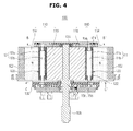
- FIG. 4 is a cross-sectional view taken along line A-A' of FIG. 2
- FIG. 5 is a plan view taken along line B-B' of FIG. 4 .
- the magnetic cooling apparatus 100 includes a magnetic regenerator unit 120 provided with plural magnetic regenerators 11 and 12, a magnet unit 110 to apply magnetic field to the magnetic regenerators 11 and 12 and withdraw the applied magnetic field, a hot-side heat exchanger 131, in which the heat transfer fluid having received heat from the magnetic regenerators 11 and 12 subjected to the magnetic field applied by the magnet unit 110 dissipates heat, a cold-side heat exchanger 132, in which the heat transfer fluid having transferred heat to the magnetic regenerators 11 and 12 released from the magnetic field by the magnet unit 110 absorbs heat, and guide flow passages 15a, 15b and 15c to connect the magnetic regenerators 11 and 12, the hot-side heat exchanger 131, and the cold-side heat exchanger 132 such that the heat transfer fluid reciprocates through the magnetic regenerators 11 and 12, the hot-side heat exchanger 131, and the cold-side heat exchanger 132.
- the magnetic regenerator unit 120 includes a cylindrical housing 104, plural magnetic regenerators 11 and 12 radially arranged in the housing 104 and spaced apart from each other along the circumferential direction of the housing 104, and a rotating shaft 106 coupled to the center of the housing 104 to rotate the housing 104.
- the magnetic regenerators 11 and 12 allow the heat transfer fluid to pass therethrough and contain a magnetocaloric material.
- the magnetic regenerators 11 and 12 include cylindrical bodies 11a and 12a, and through holes 11b and 12b formed in the longitudinal direction of the bodies 11a and 12a.
- the bodies 11a and 12a may be formed of a material such as plastics with low thermal conductivity.
- the through holes 11b and 12b are filled with a magnetocaloric material.
- the magnetocaloric material has a property that the temperature thereof changes according to application and withdrawal of the magnetic field, i.e., the magnetocaloric effect.
- Materials that has a strong magnetocaloric effect include gadolinium (Gd), manganese iron compounds (MnFe) and lanthanum iron compounds (LaFe), which are fine powders. These magnetocaloric materials have pores having high permeability for flow of the heat transfer fluid, and have high capacity to absorb and dissipate heat.
- the magnetocaloric effect is increase or decrease in temperature of the magnetocaloric material upon application or withdrawal of the magnetic field.
- Such magnetocaloric effect results from conservation of entropy.
- arrays of particles of the magnetocaloric material are ordered and temperature of the magnetocaloric material increases.
- the magnetic field is withdrawn from the magnetocaloric material, the arrays go back to the disordered state and the temperature of the magnetocaloric material decreases.
- the first magnetic regenerator 11 and the second magnetic regenerator 12 produce a cooling effect through such variation in temperature.
- connectors 121 and 122 are provided at both ends of the through holes 11b and 12b respectively connected to the guide flow passages 15a, 15b and 15c.
- the connectors 121 and 122 allows the magnetic regenerators 11 and 12 to be connected to the hot-side heat exchanger 131 and the cold-side heat exchanger 132 through the guide flow passages 15a, 15b and 15c such that the heat transfer fluid flows into the hot-side heat exchanger 131 and the cold-side heat exchanger 132 after passing through the magnetic regenerators 11 and 12. While the heat transfer fluid flows through the through holes 11b and 12b, the heat transfer fluid absorbs heat produced by the magnetocaloric material or loses heat to the magnetocaloric material by contacting the magnetocaloric material.
- the heat transfer fluid absorbs heat produced by the magnetocaloric material and flows into the hot-side heat exchanger 131, where the heat transfer fluid dissipates the heat.
- the heat transfer fluid loses heat to the magnetocaloric material and flows into the cold-side heat exchanger 132, where the heat transfer fluid absorbs heat.
- the magnet unit 110 includes plural magnets 112 and 114 having at least one pair of N and S poles.
- the magnets 112 and 114 are radially disposed at the inner and outer sides of the housing 104 to apply the magnetic field to the magnetic regenerators 11 and 12 or withdraw the applied magnetic field.
- the N poles and S poles are disposed at the inner and outer sides of the magnetic regenerator unit 120 in the circumferential direction of the magnetic regenerator unit 120.
- the magnets 112 and 114 are supported by a first magnet support 116 and a second magnet support 118 respectively arranged at the inner side and outer side of the magnetic regenerator unit 120.
- the hot-side heat exchanger 131 and the cold-side heat exchanger 132 are disposed on circulation paths of the heat transfer fluid extending in opposite directions, with the magnetic regenerator unit 120 placed between the hot-side heat exchanger 131 and the cold-side heat exchanger 132. Heating may be performed through the heat dissipation effect of the hot-side heat exchanger 131, or cooling may be performed through the heat absorption effect of the cold-side heat exchanger 132.
- Reference numeral 102 denotes the body housing of the magnetic cooling apparatus 100.
- FIG. 6 is a cross-sectional view showing the structure of the upper flow passage of the magnetic regenerator unit 120, taken along line B-B' of FIG. 4
- FIG. 7 is a cross-sectional view showing the structure of the lower flow passage of the magnetic regenerator unit 120, taken along line C-C' of FIG. 4 .
- the guide flow passages 15a, 15b and 15c are joined to one side of the magnetic regenerator unit 120 in the axial direction of the magnetic regenerator unit 120 to allow the heat transfer fluid to flow between one magnetic regenerator 11 (hereinafter, a 'first magnetic regenerator') of the magnetic regenerators 11 and 12 that is subjected to the magnetic field applied by the magnets 112 and 114 and the other magnetic regenerator 12 (hereinafter, a 'second magnetic regenerator') released from the magnetic field applied by the magnets 112 and 114.
- a 'first magnetic regenerator' one magnetic regenerator 11 of the magnetic regenerators 11 and 12 that is subjected to the magnetic field applied by the magnets 112 and 114 and the other magnetic regenerator 12 (hereinafter, a 'second magnetic regenerator') released from the magnetic field applied by the magnets 112 and 114.
- the heat transfer fluid dissipates heat to the surroundings or absorbs heat from the surroundings while circulating through the magnetic regenerator unit 120, the hot-side heat exchanger 131 and the cold-side heat exchanger 132.
- magnetization and demagnetization of the magnetocaloric material need to repeatedly occur. Accordingly, a description will be given of a drive system to rotate the first magnetic regenerator 11 and the second magnetic regenerator 12 filled with the magnetocaloric material and allowing flow of the heat transfer fluid therethrough, with reference to FIG. 8 .
- FIG. 8 is a block diagram illustrating a drive system of a rotary magnetic cooling apparatus according to one embodiment of the present disclosure.
- the drive system of the magnetic cooling apparatus 100 includes a first drive unit 140 disposed in the guide flow passage 15 of the heat transfer fluid to drive the fluid supply device 14 to circulate the heat transfer fluid, the first magnetic regenerator 11 and a second drive unit 150 to rotate the magnetic regenerator unit 120 provided with the second magnetic regenerator 12, and a controller 160 to control operation of the first drive unit 140 and the second drive unit 150.
- the fluid supply device 14 switches flow of the heat transfer fluid between two directions to supply the heat transfer fluid into the first magnetic regenerator 11 and the second magnetic regenerator 12.
- the magnetic cooling apparatus 100 includes four cooling modules 10, in which the magnetic regenerator unit 120 including eight magnetic regenerators 11 and 12 is circumferentially disposed.
- each of the cooling modules 10 needs four fluid supply devices 14 to supply the heat transfer fluid.
- the four fluid supply devices 14 are connected to each other to form one unit such that the heat transfer fluid flows in the same direction.
- the first drive unit 140 is a linear motor to drive the four fluid supply devices 14.
- the first drive unit 140 is controlled by the controller 160.
- the second drive unit 150 is a motor to rotate the magnetic regenerator unit 120 provided with the eight magnetic regenerators 11 and 12.
- the second drive unit 150 is controlled by the controller 160.
- the second drive unit 150 further includes a power transmission system to convert the driving force of the motor into rotational motion of the magnetic regenerators 11 and 12.
- the magnetic regenerator unit 120 disposed in the housing 104 and the housing 104 coupled to the rotating shaft 106 rotate about the rotating shaft 106.
- the first magnetic regenerator 11 and the second magnetic regenerator 12 of the magnetic regenerator unit 120 rotating about the rotating shaft 106 sequentially enter and leave the magnetic field formed at the inner side and outer side of the housing 106 by the magnets 112 and 114.
- the heat transfer fluid passing through the first magnetic regenerator 11 and the second magnetic regenerator 12 receives heat from the first magnetic regenerator 11 and the second magnetic regenerator 12.
- the heat transfer fluid passing through the first magnetic regenerator 11 and the second magnetic regenerator 12 transfers heat to the first magnetic regenerator 11 and the second magnetic regenerator 12.
- the heat transfer fluid flows through the guide flow passage 15 into the first magnetic regenerator 11 and the second magnetic regenerator 12 subjected to the magnetic field applied by the magnets 112 and 114.
- the heat transfer fluid introduced into the first magnetic regenerator 11 and the second magnetic regenerator 12 absorbs heat from the first magnetic regenerator 11 and the second magnetic regenerator 12. Then, the heat transfer fluid in a heated state dissipates the heat absorbed from the first magnetic regenerator 11 and the second magnetic regenerator 12 to the surroundings when transported through the guide flow passage 15.
- the heat transfer fluid completes one heat exchange cycle.
- a difference in temperature between the cold side and the hot side is produced, and heat exchange is caused in the heat exchangers 131 and 132 positioned at both ends of the first magnetic regenerator 11 and the second magnetic regenerator 12 to obtain the hot state or cold state necessary for heating or cooling.
- the magnets 112 and 114 are fixed to maintain a constant magnetization region, and the magnetic regenerator unit 120 is rotated.
- the structure of the magnetic cooling apparatus 100 is not limited thereto. That is, the magnetic regenerator unit 120 may be fixed, while the magnets 112 and 114 may rotate about the magnetic regenerator unit 120 to apply magnetic field to the first magnetic regenerator 11 and the second magnetic regenerator 12 or withdraw the applied magnetic field.
- the rotating shaft 106 may be coupled and fixed to the centers of the magnets 112 and 114, rather than to the housing 104.
- an assembly of the magnetic regenerator unit 120 and the fluid supply device 14 may be rotated.
- the magnetic cooling apparatus 100 may be designed such that one motor drives the fluid supply device 14 and rotates the first magnetic regenerator 11 and the second magnetic regenerator 12.
- a power transmission structure such as a link to convert rotational motion into rectilinear motion may be used,
- a bidirectional fluid supply device is used to supply a heat transfer fluid into magnetic regenerators subjected to or released from magnetic field, and thus necessity of a rotary sealing part is eliminated. Accordingly, fluid leakage may be prevented, and the magnetic cooling apparatus may eliminate concern over deterioration of a rubber material.
- the magnetic cooling apparatus is operable under the condition of higher frequency and higher pressure than when a rotary valve is used, higher cooling performance may be obtained.
- the simple structure of flow passages may enhance heat transfer efficiency and cooling performance, and the number of magnetic regenerators may be easily increased or reduced by providing the same in the form of a module.
Landscapes
- Engineering & Computer Science (AREA)
- Physics & Mathematics (AREA)
- Mechanical Engineering (AREA)
- Thermal Sciences (AREA)
- General Engineering & Computer Science (AREA)
- Motor Or Generator Cooling System (AREA)
- Permanent Field Magnets Of Synchronous Machinery (AREA)
Abstract
Description
- Embodiments of the present disclosure relate to a magnetic cooling apparatus using properties of a magnetocaloric material and a method of controlling the same.
- A magnetic cooling apparatus, which uses properties of a magnetocaloric material, which produces heat when magnetized in a magnetic field and absorbs heat when released from the magnetic field and is thus demagnetized, is a new cooling system that may replace conventional cooling apparatuses, which use an air compression cycle.
- The magnetic cooling apparatus generally includes a magnetic regenerator filled with a magnetocaloric material, a magnet to apply and remove a magnetic field to the magnetic regenerator, a heat exchange unit allowing a heat transfer fluid passing through the magnetic regenerator to absorb heat from or dissipate heat to the external air, and a flow passage to guide flow of the heat transfer fluid.
- Accordingly, heat transferred to the heat transfer fluid that passes through the magnetic regenerator is subjected to the magnetic field, and the heat transfer fluid releases the heat to the external air through the high-temperature heat exchanger. After releasing heat in the high-temperature heat exchanger, the heat transfer fluid loses heat while passing through the magnetic regenerator from which the magnetic field has been removed. Then, the heat transfer fluid absorbs heat from the external air through the low-temperature heat exchanger. After absorbing heat in the low-temperature heat exchanger, the heat transfer fluid flows again into the magnetic regenerator placed in the magnetic field and undergoes the same process.
- To enhance cooling performance, a rotary magnetic cooling apparatus may be employed as the magnetic cooling apparatus. In rotation of the magnetic cooling apparatus, at least one magnetic regenerator is used, and a rotary valve is installed in the flow passage to transfer the heat transfer fluid to each magnetic regenerator.
- The direction of movement of the heat transfer fluid needs to change according to the time of magnetization/demagnetization of each magnetic regenerator. Accordingly, the rotary valve needs to sequentially change in the direction of movement of the heat transfer fluid. The rotary valve needs to perform the "rotation" function and "sealing" function for the heat transfer fluid. The "rotation" function should allow two different components to rotate with a gap therebetween. The "sealing" function should allow two different components to be completely attached to each other without a gap therebetween.
- To satisfy these two functions, mechanical components such as bearings and an oil seal have been developed. These components are operable at a lower pressure. However, when the fluid is quickly reciprocated at a high frequency (1 Hz to 8 Hz), the fluid is pressurized to about 10 bar. Accordingly, the rotary seal may be broken, resulting in leakage of the fluid when the pressure becomes equal to or greater than a certain pressure.
- According to the present invention there is provided an apparatus and method as set forth in the appended claims. Other features of the invention will be apparent from the dependent claims, and the description which follows.
- Therefore, it is an aspect of the present disclosure to provide a magnetic cooling apparatus that may employ plural magnetic cooling units to address disadvantages of the rotary seal and enhance cooling performance and a method of controlling the same.
- Additional aspects of the disclosure will be set forth in part in the description which follows and, in part, will be obvious from the description, or may be learned by practice of the disclosure.
- In accordance with one aspect of the present disclosure, a magnetic cooling apparatus includes a plurality of cooling modules, each of the cooling modules including at least one magnetic regenerator allowing a heat transfer fluid to pass therethrough and filled with a magnetocaloric material, and a fluid supply device to supply the heat transfer fluid into the magnetic regenerator, wherein the cooling modules are rotatably arranged in a circumferential direction.
- The magnetic cooling apparatus may further include a plurality of magnets to apply a magnetic field to the magnetic regenerator and withdraw the applied magnetic field, wherein the cooling modules may be disposed in the magnetic field created by the magnet.
- The magnets may be disposed at an inner side and an outer side in a circular form, with the magnetic regenerator placed between the magnets.
- The magnets may be four-pole magnets configured with four magnetic field regions and four non-magnetic field regions.
- The cooling modules may be disposed between the inner-side magnets and outer-side magnets of the magnets in a circumferential direction.
- The magnetic regenerators may be arranged in an array between the inner magnets and the outer magnets to construct a magnetic regenerator unit.
- A flow passage to guide flow of the heat transfer fluid supplied to the fluid supply devices may be provided at opposite ends of the magnetic regenerator unit.
- A heat exchanger may be disposed on the flow passage provided at opposite ends of the magnetic regenerator unit.
- The fluid supply devices provided to the cooling modules may be connected to each other to form one unit such that the heat transfer fluid flows in the same direction.
- The magnetic cooling apparatus may further include a first drive unit to drive the fluid supply devices, a second drive unit to rotate the magnetic regenerators, and a controller to control operation of the first drive unit and the second drive unit.
- Each of the first drive unit and second drive unit may be a separate motor.
- The first drive unit and second drive unit may be a single motor.
- In accordance with another aspect of the present disclosure, a method of controlling a magnetic cooling apparatus includes a plurality of cooling modules, each of the cooling modules including at least one magnetic regenerator allowing a heat transfer fluid to pass therethrough and filled with a magnetocaloric material, and a fluid supply device to supply the heat transfer fluid into the magnetic regenerator, includes rotating, by a controller, the magnetic regenerator, and operating, by the controller, the fluid supply device at the time when magnetization and demagnetization of the magnetic regenerator are switched from one to the other according to rotation of the magnetic regenerator.
- The magnetic cooling apparatus may further include a plurality of magnets to apply a magnetic field to the magnetic regenerator and withdraw the applied magnetic field, the method further including operating, by the controller, the fluid supply device when magnetization and demagnetization of the magnetic regenerator are switched from one to the other according to rotation of the magnets.
- When the magnets rotate, the magnetic regenerator is fixed so as not to rotate.
- For a better understanding of the invention, and to show how embodiments of the same may be carried into effect, reference will now be made, by way of example, to the accompanying diagrammatic drawings in which:
-
FIG. 1 is a block diagram schematically illustrating a rotary magnetic cooling apparatus according to an exemplary embodiment of the present disclosure; -
FIG. 2 is a perspective view showing the entire rotary magnetic cooling apparatus according to the illustrated embodiment; -
FIG. 3 is a perspective view showing the upper portion of the rotary magnetic cooling apparatus according to the illustrated embodiment, with the heat exchanger removed therefrom; -
FIG. 4 is a cross-sectional view taken along line A-A' ofFIG. 2 ; -
FIG. 5 is a plan view taken along line B-B' ofFIG. 4 ; -
FIG. 6 is a cross-sectional view showing the structure of the upper flow passage of the magnetic regenerator unit, taken along line B-B' ofFIG. 4 ; -
FIG. 7 is a cross-sectional view showing the structure of the lower flow passage of the magnetic regenerator unit, taken along line C-C' ofFIG. 4 ; and -
FIG. 8 is a block diagram illustrating a drive system of a rotary magnetic cooling apparatus according to one embodiment of the present disclosure. - Reference will now be made in detail to the embodiments of the present disclosure, examples of which are illustrated in the accompanying drawings, wherein like reference numerals refer to like elements throughout.
-
FIG. 1 is a block diagram schematically illustrating a rotary magnetic cooling apparatus according to an exemplary embodiment of the present disclosure. - In
FIG. 1 , the rotary magnetic cooling apparatus according to this embodiment uses at least one magnetic regenerator and includes plural cooling modules. - As a basic module constituting the magnetic cooling apparatus, the
cooling module 10 includes a pair ofmagnetic regenerators magnetic regenerators guide flow passage 15 to connect themagnetic regenerators fluid supply device 14. - The pair of
magnetic regenerators magnetic regenerator 11 and a secondmagnetic regenerator 12. - As the first
magnetic regenerator 11 and the secondmagnetic regenerator 12, active magnetic regenerators (AMRs) filled with a magnetocaloric material allowing flow of the heat transfer fluid therethrough are employed. -
Magnets 13 to apply a magnetic field to the firstmagnetic regenerator 11 and the secondmagnetic regenerator 12 are installed at both sides of the firstmagnetic regenerator 11 and the secondmagnetic regenerator 12. - The N poles and S poles of the
magnets 13 are provided in at least one pair and movably arranged to apply a magnetic field to the firstmagnetic regenerator 11 and the secondmagnetic regenerator 12. - The first
magnetic regenerator 11 and the secondmagnetic regenerator 12 are driven to alternately enter and leave the magnetic field formed between the N poles and S poles of themagnets 13. The firstmagnetic regenerator 11 and the secondmagnetic regenerator 12 are magnetized when they enter the magnetic field. The firstmagnetic regenerator 11 and the secondmagnetic regenerator 12 are demagnetized when they leave the magnetic field. When the firstmagnetic regenerator 11 enters the magnetic field to be magnetized, the secondmagnetic regenerator 12 leaves the magnetic field to be demagnetized. On the other hand, when the firstmagnetic regenerator 11 leaves the magnetic field to be demagnetized, the secondmagnetic regenerator 12 enters the magnetic field to be magnetized. To allow the firstmagnetic regenerator 11 and the secondmagnetic regenerator 12 to enter and leave the magnetic field, the firstmagnetic regenerator 11 and the secondmagnetic regenerator 12 may be configured to rotate. - The
fluid supply device 14 changes flow of the heat transfer fluid between two directions (indicated by the solid line arrows and dotted line arrows) to supply the heat transfer fluid into the firstmagnetic regenerator 11 and the secondmagnetic regenerator 12. - In addition, the
fluid supply device 14 switches the flow in theguide flow passage 15 between the direction indicated by the solid line arrow and the direction indicated by the dotted line arrows at the time of magnetization and demagnetization of each of the firstmagnetic regenerator 11 and the secondmagnetic regenerator 12. - That is, when the first
magnetic regenerator 11 is magnetized and the secondmagnetic regenerator 12 is demagnetized, a high-temperature flow passage allowing the fluid to flow therethrough is formed through the magnetized firstmagnetic regenerator 11 and a low-temperature flow passage allowing the fluid to flow therethrough is formed through the demagnetized secondmagnetic regenerator 12. - In contrast, when the first
magnetic regenerator 11 is demagnetized and the secondmagnetic regenerator 12 is magnetized, a low-temperature flow passage allowing the fluid to flow therethrough is formed through the demagnetized firstmagnetic regenerator 11 and a high-temperature flow passage allowing the fluid to flow therethrough is formed through the magnetized secondmagnetic regenerator 12. - The first
magnetic regenerator 11 and the secondmagnetic regenerator 12 are continuously and alternately magnetized and demagnetized by the magnetic poles of themagnets 13. Thefluid supply device 14 begins to supply the heat transfer fluid into the firstmagnetic regenerator 11 and the secondmagnetic regenerator 12 at the time of magnetization and demagnetization. As the cycle of magnetization and demagnetization repeats, a temperature difference occurs between the cold side and the hot side. Thereby, the heat exchangers positioned at both ends of each of the cold side and the hot side perform heat exchange, implementing the cooling function of the magnetic cooling apparatus. - Accordingly, the effects of heat dissipation and heat absorption which occur when the first
magnetic regenerator 11 and the secondmagnetic regenerator 12 are magnetized and demagnetized may be used for heating and cooling. In this way, thecooling module 10 may create low temperature and high temperature environments using the heating and cooling operation of the firstmagnetic regenerator 11 and the secondmagnetic regenerator 12. - As to types of the heat transfer fluid, water, alcohols, antifreezes such as ethylene glycol, helium gas, and mixtures thereof may be used.
- The
guide flow passage 15 connects the firstmagnetic regenerator 11, the secondmagnetic regenerator 12 and thefluid supply device 14 such that the heat transfer fluid reciprocates through the firstmagnetic regenerator 11, the secondmagnetic regenerator 12 and thefluid supply device 14. - The
cooling module 10 forms a pair of closed loops. By circumferentially disposingplural cooling modules 10 configured as shown inFIG. 1 , a rotary magnetic cooling apparatus is implemented, which will be described with reference toFIGS. 2 and3 . -
FIG. 2 is a perspective view showing the entire rotary magnetic cooling apparatus according to the illustrated embodiment, andFIG. 3 is a perspective view showing the upper portion of the rotary magnetic cooling apparatus according to the illustrated embodiment, with the heat exchanger removed therefrom. - In this embodiment, the
magnetic cooling apparatus 100 includes a four-pole magnet configured with four magnetic field areas and four non-magnetic field areas, and eightmagnetic regenerators magnetic cooling apparatus 100 forms four pairs of closed loops. - In
FIGS. 2 and3 , themagnetic cooling apparatus 100 includes amagnet unit 110 divided into an inner part and an outer part according to the rotational property of the magnetic cooling apparatus and disposed in the form of a circle, and amagnetic regenerator unit 120 disposed in the magnetic field created by themagnet unit 110 divided into an inner part and an outer part. - The
magnet unit 110 employs four-pole magnets - The
magnetic regenerator unit 120 includes fourcooling modules 10 forming four pairs of closed loops, in which eightmagnetic regenerators - Each cooling
module 10 forming one pair of closed loops is provided with twomagnetic regenerators FIG. 1 ). Accordingly, themagnetic cooling apparatus 100 may be configured by disposing fourcooling modules 10 in the circumferential direction. - A
heat exchanger 130 is installed at both ends of themagnetic regenerator unit 120. In theheat exchanger 130, the heat transfer fluid having passed through themagnetic regenerators - The
heat exchanger 130 includes a hot-side heat exchanger 131 that the magnetic field having become relatively hot by receiving heat from themagnetic regenerators side heat exchanger 132 that the heat transfer fluid having become relatively cold by transferring heat to themagnetic regenerators magnet unit 110 enters and leaves. - The heat transfer fluid performs heat exchange by circulating alternately counterclockwise and clockwise according to application and withdrawal of the magnetic field to the
magnetic regenerators magnets side heat exchanger 131 or the cold-side heat exchanger 132, the heat transfer fluid having passed through themagnetic regenerators side heat exchanger 131 or the cold-side heat exchanger 132 within half the time of one heat exchange cycle. To this end, the hot-side heat exchanger 131 or the cold-side heat exchanger 132 needs to be disposed within a certain distance from themagnetic regenerators -
FIG. 4 is a cross-sectional view taken along line A-A' ofFIG. 2 , andFIG. 5 is a plan view taken along line B-B' ofFIG. 4 . - Referring to
FIGS. 4 and5 , themagnetic cooling apparatus 100 includes amagnetic regenerator unit 120 provided with pluralmagnetic regenerators magnet unit 110 to apply magnetic field to themagnetic regenerators side heat exchanger 131, in which the heat transfer fluid having received heat from themagnetic regenerators magnet unit 110 dissipates heat, a cold-side heat exchanger 132, in which the heat transfer fluid having transferred heat to themagnetic regenerators magnet unit 110 absorbs heat, and guideflow passages magnetic regenerators side heat exchanger 131, and the cold-side heat exchanger 132 such that the heat transfer fluid reciprocates through themagnetic regenerators side heat exchanger 131, and the cold-side heat exchanger 132. - The
magnetic regenerator unit 120 includes acylindrical housing 104, pluralmagnetic regenerators housing 104 and spaced apart from each other along the circumferential direction of thehousing 104, and arotating shaft 106 coupled to the center of thehousing 104 to rotate thehousing 104. - The
magnetic regenerators magnetic regenerators cylindrical bodies holes bodies bodies holes - The magnetocaloric material has a property that the temperature thereof changes according to application and withdrawal of the magnetic field, i.e., the magnetocaloric effect. Materials that has a strong magnetocaloric effect include gadolinium (Gd), manganese iron compounds (MnFe) and lanthanum iron compounds (LaFe), which are fine powders. These magnetocaloric materials have pores having high permeability for flow of the heat transfer fluid, and have high capacity to absorb and dissipate heat.
- The magnetocaloric effect is increase or decrease in temperature of the magnetocaloric material upon application or withdrawal of the magnetic field. Such magnetocaloric effect results from conservation of entropy. When the magnetic field is applied to the magnetocaloric material, arrays of particles of the magnetocaloric material are ordered and temperature of the magnetocaloric material increases. When the magnetic field is withdrawn from the magnetocaloric material, the arrays go back to the disordered state and the temperature of the magnetocaloric material decreases. The first
magnetic regenerator 11 and the secondmagnetic regenerator 12 produce a cooling effect through such variation in temperature. - Provided at both ends of the through
holes connectors guide flow passages connectors magnetic regenerators side heat exchanger 131 and the cold-side heat exchanger 132 through theguide flow passages side heat exchanger 131 and the cold-side heat exchanger 132 after passing through themagnetic regenerators holes magnetic regenerators side heat exchanger 131, where the heat transfer fluid dissipates the heat. When themagnetic regenerators side heat exchanger 132, where the heat transfer fluid absorbs heat. - The
magnet unit 110 includesplural magnets magnets housing 104 to apply the magnetic field to themagnetic regenerators magnetic regenerator unit 120 in the circumferential direction of themagnetic regenerator unit 120. Themagnets first magnet support 116 and asecond magnet support 118 respectively arranged at the inner side and outer side of themagnetic regenerator unit 120. - The hot-
side heat exchanger 131 and the cold-side heat exchanger 132 are disposed on circulation paths of the heat transfer fluid extending in opposite directions, with themagnetic regenerator unit 120 placed between the hot-side heat exchanger 131 and the cold-side heat exchanger 132. Heating may be performed through the heat dissipation effect of the hot-side heat exchanger 131, or cooling may be performed through the heat absorption effect of the cold-side heat exchanger 132. -
Reference numeral 102 denotes the body housing of themagnetic cooling apparatus 100. -
FIG. 6 is a cross-sectional view showing the structure of the upper flow passage of themagnetic regenerator unit 120, taken along line B-B' ofFIG. 4 ,FIG. 7 is a cross-sectional view showing the structure of the lower flow passage of themagnetic regenerator unit 120, taken along line C-C' ofFIG. 4 . - Referring to
FIGS. 6 and7 , theguide flow passages magnetic regenerator unit 120 in the axial direction of themagnetic regenerator unit 120 to allow the heat transfer fluid to flow between one magnetic regenerator 11 (hereinafter, a 'first magnetic regenerator') of themagnetic regenerators magnets magnets - Hereinafter, a description will be given of the process in which the heat transfer fluid dissipates heat to the surroundings or absorbs heat from the surroundings while circulating through the
magnetic regenerator unit 120, the hot-side heat exchanger 131 and the cold-side heat exchanger 132. - For the
magnetic cooling apparatus 100 to use the magnetocaloric effect of a magnetocaloric material, magnetization and demagnetization of the magnetocaloric material need to repeatedly occur. Accordingly, a description will be given of a drive system to rotate the firstmagnetic regenerator 11 and the secondmagnetic regenerator 12 filled with the magnetocaloric material and allowing flow of the heat transfer fluid therethrough, with reference toFIG. 8 . -
FIG. 8 is a block diagram illustrating a drive system of a rotary magnetic cooling apparatus according to one embodiment of the present disclosure. - Referring to
FIG. 8 , the drive system of themagnetic cooling apparatus 100 includes afirst drive unit 140 disposed in theguide flow passage 15 of the heat transfer fluid to drive thefluid supply device 14 to circulate the heat transfer fluid, the firstmagnetic regenerator 11 and asecond drive unit 150 to rotate themagnetic regenerator unit 120 provided with the secondmagnetic regenerator 12, and acontroller 160 to control operation of thefirst drive unit 140 and thesecond drive unit 150. - The
fluid supply device 14 switches flow of the heat transfer fluid between two directions to supply the heat transfer fluid into the firstmagnetic regenerator 11 and the secondmagnetic regenerator 12. - According to this embodiment, the
magnetic cooling apparatus 100 includes fourcooling modules 10, in which themagnetic regenerator unit 120 including eightmagnetic regenerators - Accordingly, each of the
cooling modules 10 needs fourfluid supply devices 14 to supply the heat transfer fluid. The fourfluid supply devices 14 are connected to each other to form one unit such that the heat transfer fluid flows in the same direction. - The
first drive unit 140 is a linear motor to drive the fourfluid supply devices 14. Thefirst drive unit 140 is controlled by thecontroller 160. - The
second drive unit 150 is a motor to rotate themagnetic regenerator unit 120 provided with the eightmagnetic regenerators second drive unit 150 is controlled by thecontroller 160. - In addition, the
second drive unit 150 further includes a power transmission system to convert the driving force of the motor into rotational motion of themagnetic regenerators - As the
rotating shaft 106 connected to thesecond drive unit 150 rotates, themagnetic regenerator unit 120 disposed in thehousing 104 and thehousing 104 coupled to therotating shaft 106 rotate about therotating shaft 106. The firstmagnetic regenerator 11 and the secondmagnetic regenerator 12 of themagnetic regenerator unit 120 rotating about therotating shaft 106 sequentially enter and leave the magnetic field formed at the inner side and outer side of thehousing 106 by themagnets magnetic regenerator 11 and the secondmagnetic regenerator 12 enter the magnetic field, the heat transfer fluid passing through the firstmagnetic regenerator 11 and the secondmagnetic regenerator 12 receives heat from the firstmagnetic regenerator 11 and the secondmagnetic regenerator 12. When the firstmagnetic regenerator 11 and the secondmagnetic regenerator 12 leave the magnetic field, the heat transfer fluid passing through the firstmagnetic regenerator 11 and the secondmagnetic regenerator 12 transfers heat to the firstmagnetic regenerator 11 and the secondmagnetic regenerator 12. - Accordingly, after dissipating heat to the surroundings, the heat transfer fluid flows through the
guide flow passage 15 into the firstmagnetic regenerator 11 and the secondmagnetic regenerator 12 subjected to the magnetic field applied by themagnets - The heat transfer fluid introduced into the first
magnetic regenerator 11 and the secondmagnetic regenerator 12 absorbs heat from the firstmagnetic regenerator 11 and the secondmagnetic regenerator 12. Then, the heat transfer fluid in a heated state dissipates the heat absorbed from the firstmagnetic regenerator 11 and the secondmagnetic regenerator 12 to the surroundings when transported through theguide flow passage 15. - Through this process, the heat transfer fluid completes one heat exchange cycle. By successive repetition of the heat exchange cycle through magnetization and demagnetization of the first
magnetic regenerator 11 and the secondmagnetic regenerator 12 during rotation about therotating shaft 106, a difference in temperature between the cold side and the hot side is produced, and heat exchange is caused in theheat exchangers magnetic regenerator 11 and the secondmagnetic regenerator 12 to obtain the hot state or cold state necessary for heating or cooling. - In the illustrated embodiment, the
magnets magnetic regenerator unit 120 is rotated. However, the structure of themagnetic cooling apparatus 100 is not limited thereto. That is, themagnetic regenerator unit 120 may be fixed, while themagnets magnetic regenerator unit 120 to apply magnetic field to the firstmagnetic regenerator 11 and the secondmagnetic regenerator 12 or withdraw the applied magnetic field. In this case, therotating shaft 106 may be coupled and fixed to the centers of themagnets housing 104. - Alternatively, an assembly of the
magnetic regenerator unit 120 and thefluid supply device 14 may be rotated. - In the illustrated embodiment, separate motors are employed as the
first drive unit 140 to drive thefluid supply device 14 and thesecond drive unit 150 to rotate themagnetic regenerator unit 120. However, embodiments of themagnetic cooling apparatus 100 are not limited thereto. That is, themagnetic cooling apparatus 100 may be designed such that one motor drives thefluid supply device 14 and rotates the firstmagnetic regenerator 11 and the secondmagnetic regenerator 12. In this case, a power transmission structure such as a link to convert rotational motion into rectilinear motion may be used, - As is apparent from the above description, according to embodiments of a magnetic cooling apparatus and a method of controlling the same, a bidirectional fluid supply device is used to supply a heat transfer fluid into magnetic regenerators subjected to or released from magnetic field, and thus necessity of a rotary sealing part is eliminated. Accordingly, fluid leakage may be prevented, and the magnetic cooling apparatus may eliminate concern over deterioration of a rubber material. In addition, since the magnetic cooling apparatus is operable under the condition of higher frequency and higher pressure than when a rotary valve is used, higher cooling performance may be obtained. In addition, the simple structure of flow passages may enhance heat transfer efficiency and cooling performance, and the number of magnetic regenerators may be easily increased or reduced by providing the same in the form of a module.
- Although a few preferred embodiments have been shown and described, it will be appreciated by those skilled in the art that various changes and modifications might be made without departing from the scope of the invention, as defined in the appended claims.
- Attention is directed to all papers and documents which are filed concurrently with or previous to this specification in connection with this application and which are open to public inspection with this specification, and the contents of all such papers and documents are incorporated herein by reference.
- All of the features disclosed in this specification (including any accompanying claims and drawings), and/or all of the steps of any method or process so disclosed, may be combined in any combination, except combinations where at least some of such features and/or steps are mutually exclusive.
- Each feature disclosed in this specification (including any accompanying claims and drawings) may be replaced by alternative features serving the same, equivalent or similar purpose, unless expressly stated otherwise. Thus, unless expressly stated otherwise, each feature disclosed is one example only of a generic series of equivalent or similar features.
- The invention is not restricted to the details of the foregoing embodiment(s). The invention extends to any novel one, or any novel combination, of the features disclosed in this specification (including any accompanying claims and drawings), or to any novel one, or any novel combination, of the steps of any method or process so disclosed.
Claims (15)
- A magnetic cooling apparatus comprising a plurality of cooling modules, each of the cooling modules including:at least one magnetic regenerator allowing a heat transfer fluid to pass therethrough and filled with a magnetocaloric material; anda fluid supply device to supply the heat transfer fluid into the magnetic regenerator,wherein the cooling modules are rotatably arranged in a circumferential direction.
- The magnetic cooling apparatus according to claim 1, further comprising a plurality of magnets to apply a magnetic field to the magnetic regenerator and withdraw the applied magnetic field,
wherein the cooling modules are disposed in the magnetic field created by the magnet. - The magnetic cooling apparatus according to claim 2, wherein the magnets are disposed at an inner side and an outer side in a circular form, with the magnetic regenerator placed between the magnets.
- The magnetic cooling apparatus according to claim 2, wherein the magnets are four-pole magnets configured with four magnetic field regions and four non-magnetic field regions.
- The magnetic cooling apparatus according to claim 3, wherein the cooling modules are disposed between the inner-side magnets and outer-side magnets of the magnets in a circumferential direction.
- The magnetic cooling apparatus according to claim 3, wherein the magnetic regenerators are arranged in an array between the inner magnets and the outer magnets to construct a magnetic regenerator unit.
- The magnetic cooling apparatus according to claim 6, wherein a flow passage to guide flow of the heat transfer fluid supplied to the fluid supply devices is provided at opposite ends of the magnetic regenerator unit.
- The magnetic cooling apparatus according to claim 7, wherein a heat exchanger is disposed on the flow passage provided at opposite ends of the magnetic regenerator unit.
- The magnetic cooling apparatus according to claim 1, wherein the fluid supply devices provided to the cooling modules are connected to each other to form one unit such that the heat transfer fluid flows in the same direction.
- The magnetic cooling apparatus according to claim 1, further comprising:a first drive unit to drive the fluid supply devices;a second drive unit to rotate the magnetic regenerators; anda controller to control operation of the first drive unit and the second drive unit.
- The magnetic cooling apparatus according to claim 10, wherein each of the first drive unit and second drive unit is includes a separate motor.
- The magnetic cooling apparatus according to claim 10, wherein the first drive unit and second drive unit are a single motor.
- A method of controlling a magnetic cooling apparatus including a plurality of cooling modules, each of the cooling modules including at least one magnetic regenerator allowing a heat transfer fluid to pass therethrough and filled with a magnetocaloric material, and a fluid supply device to supply the heat transfer fluid into the magnetic regenerator, the method comprising:rotating, by a controller, the magnetic regenerator; andoperating, by the controller, the fluid supply device at the time when magnetization and demagnetization of the magnetic regenerator are switched from one to the other according to rotation of the magnetic regenerator.
- The method according to claim 13, wherein the magnetic cooling apparatus further includes a plurality of magnets to apply a magnetic field to the magnetic regenerator and withdraw the applied magnetic field,
the method further comprising operating, by the controller, the fluid supply device when magnetization and demagnetization of the magnetic regenerator are switched from one to the other according to rotation of the magnets. - The method according to claim 14, wherein, when the magnets rotate, the magnetic regenerator is fixed so as not to rotate.
Applications Claiming Priority (1)
| Application Number | Priority Date | Filing Date | Title |
|---|---|---|---|
| KR1020130067032A KR102086373B1 (en) | 2013-06-12 | 2013-06-12 | Magnetic cooling apparatus and method of controlling the same |
Publications (2)
| Publication Number | Publication Date |
|---|---|
| EP2813785A1 true EP2813785A1 (en) | 2014-12-17 |
| EP2813785B1 EP2813785B1 (en) | 2020-12-30 |
Family
ID=50230892
Family Applications (1)
| Application Number | Title | Priority Date | Filing Date |
|---|---|---|---|
| EP14157166.1A Active EP2813785B1 (en) | 2013-06-12 | 2014-02-28 | Magnetic cooling apparatus and method of controlling the same |
Country Status (3)
| Country | Link |
|---|---|
| US (1) | US9784482B2 (en) |
| EP (1) | EP2813785B1 (en) |
| KR (1) | KR102086373B1 (en) |
Cited By (19)
| Publication number | Priority date | Publication date | Assignee | Title |
|---|---|---|---|---|
| DE102015208696A1 (en) | 2015-05-11 | 2016-11-17 | Siemens Aktiengesellschaft | switchgear module |
| CN108351126A (en) * | 2015-11-13 | 2018-07-31 | 巴斯夫欧洲公司 | Magnetocaloric heat pump, cooling device and method of operation thereof |
| US10684044B2 (en) * | 2018-07-17 | 2020-06-16 | Haier Us Appliance Solutions, Inc. | Magneto-caloric thermal diode assembly with a rotating heat exchanger |
| US10782051B2 (en) | 2018-04-18 | 2020-09-22 | Haier Us Appliance Solutions, Inc. | Magneto-caloric thermal diode assembly |
| US10830506B2 (en) | 2018-04-18 | 2020-11-10 | Haier Us Appliance Solutions, Inc. | Variable speed magneto-caloric thermal diode assembly |
| US10876770B2 (en) | 2018-04-18 | 2020-12-29 | Haier Us Appliance Solutions, Inc. | Method for operating an elasto-caloric heat pump with variable pre-strain |
| US10989449B2 (en) | 2018-05-10 | 2021-04-27 | Haier Us Appliance Solutions, Inc. | Magneto-caloric thermal diode assembly with radial supports |
| US11009282B2 (en) | 2017-03-28 | 2021-05-18 | Haier Us Appliance Solutions, Inc. | Refrigerator appliance with a caloric heat pump |
| US11015842B2 (en) | 2018-05-10 | 2021-05-25 | Haier Us Appliance Solutions, Inc. | Magneto-caloric thermal diode assembly with radial polarity alignment |
| US11015843B2 (en) | 2019-05-29 | 2021-05-25 | Haier Us Appliance Solutions, Inc. | Caloric heat pump hydraulic system |
| US11022348B2 (en) | 2017-12-12 | 2021-06-01 | Haier Us Appliance Solutions, Inc. | Caloric heat pump for an appliance |
| US11054176B2 (en) | 2018-05-10 | 2021-07-06 | Haier Us Appliance Solutions, Inc. | Magneto-caloric thermal diode assembly with a modular magnet system |
| US11092364B2 (en) | 2018-07-17 | 2021-08-17 | Haier Us Appliance Solutions, Inc. | Magneto-caloric thermal diode assembly with a heat transfer fluid circuit |
| US11112146B2 (en) | 2019-02-12 | 2021-09-07 | Haier Us Appliance Solutions, Inc. | Heat pump and cascaded caloric regenerator assembly |
| US11149994B2 (en) | 2019-01-08 | 2021-10-19 | Haier Us Appliance Solutions, Inc. | Uneven flow valve for a caloric regenerator |
| US11168926B2 (en) | 2019-01-08 | 2021-11-09 | Haier Us Appliance Solutions, Inc. | Leveraged mechano-caloric heat pump |
| US11193697B2 (en) | 2019-01-08 | 2021-12-07 | Haier Us Appliance Solutions, Inc. | Fan speed control method for caloric heat pump systems |
| US11274860B2 (en) | 2019-01-08 | 2022-03-15 | Haier Us Appliance Solutions, Inc. | Mechano-caloric stage with inner and outer sleeves |
| EP4027078A4 (en) * | 2019-09-30 | 2023-10-25 | Daikin Industries, Ltd. | SOLID STATE COOLING MODULE |
Families Citing this family (23)
| Publication number | Priority date | Publication date | Assignee | Title |
|---|---|---|---|---|
| DE102015105346A1 (en) * | 2015-04-09 | 2016-10-13 | Eberspächer Climate Control Systems GmbH & Co. KG | Temperature control unit, in particular Fahrzeugtemperiergerät |
| US10541070B2 (en) | 2016-04-25 | 2020-01-21 | Haier Us Appliance Solutions, Inc. | Method for forming a bed of stabilized magneto-caloric material |
| US10274231B2 (en) | 2016-07-19 | 2019-04-30 | Haier Us Appliance Solutions, Inc. | Caloric heat pump system |
| US10281177B2 (en) | 2016-07-19 | 2019-05-07 | Haier Us Appliance Solutions, Inc. | Caloric heat pump system |
| US10443585B2 (en) | 2016-08-26 | 2019-10-15 | Haier Us Appliance Solutions, Inc. | Pump for a heat pump system |
| US10386096B2 (en) | 2016-12-06 | 2019-08-20 | Haier Us Appliance Solutions, Inc. | Magnet assembly for a magneto-caloric heat pump |
| US10527325B2 (en) | 2017-03-28 | 2020-01-07 | Haier Us Appliance Solutions, Inc. | Refrigerator appliance |
| US10451320B2 (en) | 2017-05-25 | 2019-10-22 | Haier Us Appliance Solutions, Inc. | Refrigerator appliance with water condensing features |
| US10451322B2 (en) | 2017-07-19 | 2019-10-22 | Haier Us Appliance Solutions, Inc. | Refrigerator appliance with a caloric heat pump |
| US10422555B2 (en) * | 2017-07-19 | 2019-09-24 | Haier Us Appliance Solutions, Inc. | Refrigerator appliance with a caloric heat pump |
| US10520229B2 (en) | 2017-11-14 | 2019-12-31 | Haier Us Appliance Solutions, Inc. | Caloric heat pump for an appliance |
| US11686509B2 (en) | 2017-11-28 | 2023-06-27 | Lg Electronics Inc. | Magnetic cooling system |
| KR102042204B1 (en) * | 2017-12-26 | 2019-11-07 | 엘지전자 주식회사 | A Refrigerator System Using Magnetocaloric Material |
| US10648704B2 (en) | 2018-04-18 | 2020-05-12 | Haier Us Appliance Solutions, Inc. | Magneto-caloric thermal diode assembly |
| US10648706B2 (en) | 2018-04-18 | 2020-05-12 | Haier Us Appliance Solutions, Inc. | Magneto-caloric thermal diode assembly with an axially pinned magneto-caloric cylinder |
| US10648705B2 (en) | 2018-04-18 | 2020-05-12 | Haier Us Appliance Solutions, Inc. | Magneto-caloric thermal diode assembly |
| US10641539B2 (en) | 2018-04-18 | 2020-05-05 | Haier Us Appliance Solutions, Inc. | Magneto-caloric thermal diode assembly |
| US10557649B2 (en) | 2018-04-18 | 2020-02-11 | Haier Us Appliance Solutions, Inc. | Variable temperature magneto-caloric thermal diode assembly |
| US10551095B2 (en) | 2018-04-18 | 2020-02-04 | Haier Us Appliance Solutions, Inc. | Magneto-caloric thermal diode assembly |
| JP6884296B1 (en) * | 2020-07-17 | 2021-06-09 | 三菱電機株式会社 | Magnetic refrigerator |
| KR102434289B1 (en) * | 2020-10-26 | 2022-08-19 | 주식회사 성우하이텍 | Battery cooling system for vehicles |
| CN114183948B (en) * | 2021-12-16 | 2023-07-04 | 中国科学院江西稀土研究院 | Multi-field coupling solid-state refrigeration device |
| CN115355631B (en) * | 2022-07-26 | 2024-02-20 | 包头稀土研究院 | High-efficiency and high-power magnetic machine and its refrigeration method |
Citations (4)
| Publication number | Priority date | Publication date | Assignee | Title |
|---|---|---|---|---|
| US20050120720A1 (en) * | 2003-12-04 | 2005-06-09 | Chih-Hsing Fang | Reciprocating and rotary magnetic refrigeration apparatus |
| EP1847788A1 (en) * | 2001-12-12 | 2007-10-24 | Astronautics Corporation Of America | Rotating magnet magnetic refrigerator |
| US20100236258A1 (en) * | 2007-10-30 | 2010-09-23 | Cooltech Applications S.A.S. | Thermal generator with magneto-caloric material |
| US20120272665A1 (en) * | 2011-04-26 | 2012-11-01 | Denso Corporation | Magnetic heat pump apparatus |
Family Cites Families (5)
| Publication number | Priority date | Publication date | Assignee | Title |
|---|---|---|---|---|
| WO2008007834A1 (en) * | 2006-07-10 | 2008-01-17 | Daewoo Electronics Corporation | Shuttle type magnetic refrigerator |
| US8209988B2 (en) * | 2008-09-24 | 2012-07-03 | Husssmann Corporation | Magnetic refrigeration device |
| US20110061399A1 (en) * | 2009-09-17 | 2011-03-17 | Chang Shao Hsiung | Heat-power conversion magnetism devices |
| JP5267613B2 (en) * | 2011-04-25 | 2013-08-21 | 株式会社デンソー | Magneto-caloric effect type heat pump device |
| US10465951B2 (en) * | 2013-01-10 | 2019-11-05 | Haier Us Appliance Solutions, Inc. | Magneto caloric heat pump with variable magnetization |
-
2013
- 2013-06-12 KR KR1020130067032A patent/KR102086373B1/en active Active
-
2014
- 2014-02-28 EP EP14157166.1A patent/EP2813785B1/en active Active
- 2014-05-27 US US14/287,542 patent/US9784482B2/en active Active
Patent Citations (4)
| Publication number | Priority date | Publication date | Assignee | Title |
|---|---|---|---|---|
| EP1847788A1 (en) * | 2001-12-12 | 2007-10-24 | Astronautics Corporation Of America | Rotating magnet magnetic refrigerator |
| US20050120720A1 (en) * | 2003-12-04 | 2005-06-09 | Chih-Hsing Fang | Reciprocating and rotary magnetic refrigeration apparatus |
| US20100236258A1 (en) * | 2007-10-30 | 2010-09-23 | Cooltech Applications S.A.S. | Thermal generator with magneto-caloric material |
| US20120272665A1 (en) * | 2011-04-26 | 2012-11-01 | Denso Corporation | Magnetic heat pump apparatus |
Cited By (21)
| Publication number | Priority date | Publication date | Assignee | Title |
|---|---|---|---|---|
| WO2016180575A1 (en) | 2015-05-11 | 2016-11-17 | Siemens Aktiengesellschaft | Switchgear module |
| DE102015208696A1 (en) | 2015-05-11 | 2016-11-17 | Siemens Aktiengesellschaft | switchgear module |
| CN108351126A (en) * | 2015-11-13 | 2018-07-31 | 巴斯夫欧洲公司 | Magnetocaloric heat pump, cooling device and method of operation thereof |
| US11009282B2 (en) | 2017-03-28 | 2021-05-18 | Haier Us Appliance Solutions, Inc. | Refrigerator appliance with a caloric heat pump |
| US11022348B2 (en) | 2017-12-12 | 2021-06-01 | Haier Us Appliance Solutions, Inc. | Caloric heat pump for an appliance |
| US10782051B2 (en) | 2018-04-18 | 2020-09-22 | Haier Us Appliance Solutions, Inc. | Magneto-caloric thermal diode assembly |
| US10830506B2 (en) | 2018-04-18 | 2020-11-10 | Haier Us Appliance Solutions, Inc. | Variable speed magneto-caloric thermal diode assembly |
| US10876770B2 (en) | 2018-04-18 | 2020-12-29 | Haier Us Appliance Solutions, Inc. | Method for operating an elasto-caloric heat pump with variable pre-strain |
| US11015842B2 (en) | 2018-05-10 | 2021-05-25 | Haier Us Appliance Solutions, Inc. | Magneto-caloric thermal diode assembly with radial polarity alignment |
| US10989449B2 (en) | 2018-05-10 | 2021-04-27 | Haier Us Appliance Solutions, Inc. | Magneto-caloric thermal diode assembly with radial supports |
| US11054176B2 (en) | 2018-05-10 | 2021-07-06 | Haier Us Appliance Solutions, Inc. | Magneto-caloric thermal diode assembly with a modular magnet system |
| US11092364B2 (en) | 2018-07-17 | 2021-08-17 | Haier Us Appliance Solutions, Inc. | Magneto-caloric thermal diode assembly with a heat transfer fluid circuit |
| US10684044B2 (en) * | 2018-07-17 | 2020-06-16 | Haier Us Appliance Solutions, Inc. | Magneto-caloric thermal diode assembly with a rotating heat exchanger |
| US11149994B2 (en) | 2019-01-08 | 2021-10-19 | Haier Us Appliance Solutions, Inc. | Uneven flow valve for a caloric regenerator |
| US11168926B2 (en) | 2019-01-08 | 2021-11-09 | Haier Us Appliance Solutions, Inc. | Leveraged mechano-caloric heat pump |
| US11193697B2 (en) | 2019-01-08 | 2021-12-07 | Haier Us Appliance Solutions, Inc. | Fan speed control method for caloric heat pump systems |
| US11274860B2 (en) | 2019-01-08 | 2022-03-15 | Haier Us Appliance Solutions, Inc. | Mechano-caloric stage with inner and outer sleeves |
| US11112146B2 (en) | 2019-02-12 | 2021-09-07 | Haier Us Appliance Solutions, Inc. | Heat pump and cascaded caloric regenerator assembly |
| US11015843B2 (en) | 2019-05-29 | 2021-05-25 | Haier Us Appliance Solutions, Inc. | Caloric heat pump hydraulic system |
| EP4027078A4 (en) * | 2019-09-30 | 2023-10-25 | Daikin Industries, Ltd. | SOLID STATE COOLING MODULE |
| US12196459B2 (en) | 2019-09-30 | 2025-01-14 | Daikin Industries, Ltd. | Solid-state cooling module |
Also Published As
| Publication number | Publication date |
|---|---|
| KR102086373B1 (en) | 2020-03-10 |
| US20140366557A1 (en) | 2014-12-18 |
| KR20140145232A (en) | 2014-12-23 |
| EP2813785B1 (en) | 2020-12-30 |
| US9784482B2 (en) | 2017-10-10 |
Similar Documents
| Publication | Publication Date | Title |
|---|---|---|
| US9784482B2 (en) | Magnetic cooling apparatus and method of controlling the same | |
| JP5278486B2 (en) | Thermomagnetic engine device and reversible thermomagnetic cycle device | |
| JP5267689B2 (en) | Magnetic heat pump device | |
| CN105452783B (en) | Magnetic cooling device | |
| US8191375B2 (en) | Device for generating cold and heat by a magneto-calorific effect | |
| US10598411B2 (en) | Magnetic refrigerating device | |
| CN107726664B (en) | Magnetic Refrigerator | |
| CN107076478A (en) | With the magnetic refrigerating system not blown not etc. | |
| KR20040062989A (en) | Rotating magnet magnetic refrigerator | |
| JP2012229831A (en) | Heat pump device of magneto-caloric effect type | |
| JP6003879B2 (en) | Thermomagnetic cycle equipment | |
| US20200003461A1 (en) | Magnetic Heat Pump Apparatus | |
| KR101954538B1 (en) | A Refrigerator System Using Magnetocaloric Material | |
| US9562706B2 (en) | Magnetic cooling apparatus | |
| KR101204325B1 (en) | Compact active magnetic regenerative refrigerator | |
| US9322579B2 (en) | Thermo-magnetic cycle apparatus | |
| US20200191449A1 (en) | Magnetic Heat Pump Device | |
| JP6060789B2 (en) | Thermomagnetic cycle equipment | |
| JP2012167881A (en) | Heat exchanger of magnetic temperature regulator | |
| WO2018088167A1 (en) | Magnetic heat pump device | |
| JP7030658B2 (en) | Magnetic refrigerator | |
| JP6601300B2 (en) | Thermomagnetic cycle equipment | |
| JP6683138B2 (en) | Thermomagnetic cycle device | |
| JP2019086170A (en) | Thermomagnetic cycle device |
Legal Events
| Date | Code | Title | Description |
|---|---|---|---|
| 17P | Request for examination filed |
Effective date: 20140228 |
|
| AK | Designated contracting states |
Kind code of ref document: A1 Designated state(s): AL AT BE BG CH CY CZ DE DK EE ES FI FR GB GR HR HU IE IS IT LI LT LU LV MC MK MT NL NO PL PT RO RS SE SI SK SM TR |
|
| AX | Request for extension of the european patent |
Extension state: BA ME |
|
| PUAI | Public reference made under article 153(3) epc to a published international application that has entered the european phase |
Free format text: ORIGINAL CODE: 0009012 |
|
| R17P | Request for examination filed (corrected) |
Effective date: 20150601 |
|
| RBV | Designated contracting states (corrected) |
Designated state(s): AL AT BE BG CH CY CZ DE DK EE ES FI FR GB GR HR HU IE IS IT LI LT LU LV MC MK MT NL NO PL PT RO RS SE SI SK SM TR |
|
| STAA | Information on the status of an ep patent application or granted ep patent |
Free format text: STATUS: EXAMINATION IS IN PROGRESS |
|
| 17Q | First examination report despatched |
Effective date: 20200227 |
|
| GRAP | Despatch of communication of intention to grant a patent |
Free format text: ORIGINAL CODE: EPIDOSNIGR1 |
|
| STAA | Information on the status of an ep patent application or granted ep patent |
Free format text: STATUS: GRANT OF PATENT IS INTENDED |
|
| INTG | Intention to grant announced |
Effective date: 20200731 |
|
| GRAS | Grant fee paid |
Free format text: ORIGINAL CODE: EPIDOSNIGR3 |
|
| GRAA | (expected) grant |
Free format text: ORIGINAL CODE: 0009210 |
|
| STAA | Information on the status of an ep patent application or granted ep patent |
Free format text: STATUS: THE PATENT HAS BEEN GRANTED |
|
| RAP1 | Party data changed (applicant data changed or rights of an application transferred) |
Owner name: SAMSUNG ELECTRONICS CO., LTD. |
|
| AK | Designated contracting states |
Kind code of ref document: B1 Designated state(s): AL AT BE BG CH CY CZ DE DK EE ES FI FR GB GR HR HU IE IS IT LI LT LU LV MC MK MT NL NO PL PT RO RS SE SI SK SM TR |
|
| REG | Reference to a national code |
Ref country code: GB Ref legal event code: FG4D |
|
| REG | Reference to a national code |
Ref country code: AT Ref legal event code: REF Ref document number: 1350330 Country of ref document: AT Kind code of ref document: T Effective date: 20210115 |
|
| REG | Reference to a national code |
Ref country code: DE Ref legal event code: R096 Ref document number: 602014073739 Country of ref document: DE |
|
| REG | Reference to a national code |
Ref country code: IE Ref legal event code: FG4D |
|
| PG25 | Lapsed in a contracting state [announced via postgrant information from national office to epo] |
Ref country code: GR Free format text: LAPSE BECAUSE OF FAILURE TO SUBMIT A TRANSLATION OF THE DESCRIPTION OR TO PAY THE FEE WITHIN THE PRESCRIBED TIME-LIMIT Effective date: 20210331 Ref country code: FI Free format text: LAPSE BECAUSE OF FAILURE TO SUBMIT A TRANSLATION OF THE DESCRIPTION OR TO PAY THE FEE WITHIN THE PRESCRIBED TIME-LIMIT Effective date: 20201230 Ref country code: RS Free format text: LAPSE BECAUSE OF FAILURE TO SUBMIT A TRANSLATION OF THE DESCRIPTION OR TO PAY THE FEE WITHIN THE PRESCRIBED TIME-LIMIT Effective date: 20201230 Ref country code: NO Free format text: LAPSE BECAUSE OF FAILURE TO SUBMIT A TRANSLATION OF THE DESCRIPTION OR TO PAY THE FEE WITHIN THE PRESCRIBED TIME-LIMIT Effective date: 20210330 |
|
| REG | Reference to a national code |
Ref country code: AT Ref legal event code: MK05 Ref document number: 1350330 Country of ref document: AT Kind code of ref document: T Effective date: 20201230 |
|
| PG25 | Lapsed in a contracting state [announced via postgrant information from national office to epo] |
Ref country code: BG Free format text: LAPSE BECAUSE OF FAILURE TO SUBMIT A TRANSLATION OF THE DESCRIPTION OR TO PAY THE FEE WITHIN THE PRESCRIBED TIME-LIMIT Effective date: 20210330 Ref country code: LV Free format text: LAPSE BECAUSE OF FAILURE TO SUBMIT A TRANSLATION OF THE DESCRIPTION OR TO PAY THE FEE WITHIN THE PRESCRIBED TIME-LIMIT Effective date: 20201230 Ref country code: SE Free format text: LAPSE BECAUSE OF FAILURE TO SUBMIT A TRANSLATION OF THE DESCRIPTION OR TO PAY THE FEE WITHIN THE PRESCRIBED TIME-LIMIT Effective date: 20201230 |
|
| REG | Reference to a national code |
Ref country code: NL Ref legal event code: MP Effective date: 20201230 |
|
| PG25 | Lapsed in a contracting state [announced via postgrant information from national office to epo] |
Ref country code: HR Free format text: LAPSE BECAUSE OF FAILURE TO SUBMIT A TRANSLATION OF THE DESCRIPTION OR TO PAY THE FEE WITHIN THE PRESCRIBED TIME-LIMIT Effective date: 20201230 |
|
| REG | Reference to a national code |
Ref country code: LT Ref legal event code: MG9D |
|
| PG25 | Lapsed in a contracting state [announced via postgrant information from national office to epo] |
Ref country code: SK Free format text: LAPSE BECAUSE OF FAILURE TO SUBMIT A TRANSLATION OF THE DESCRIPTION OR TO PAY THE FEE WITHIN THE PRESCRIBED TIME-LIMIT Effective date: 20201230 Ref country code: PT Free format text: LAPSE BECAUSE OF FAILURE TO SUBMIT A TRANSLATION OF THE DESCRIPTION OR TO PAY THE FEE WITHIN THE PRESCRIBED TIME-LIMIT Effective date: 20210430 Ref country code: RO Free format text: LAPSE BECAUSE OF FAILURE TO SUBMIT A TRANSLATION OF THE DESCRIPTION OR TO PAY THE FEE WITHIN THE PRESCRIBED TIME-LIMIT Effective date: 20201230 Ref country code: LT Free format text: LAPSE BECAUSE OF FAILURE TO SUBMIT A TRANSLATION OF THE DESCRIPTION OR TO PAY THE FEE WITHIN THE PRESCRIBED TIME-LIMIT Effective date: 20201230 Ref country code: CZ Free format text: LAPSE BECAUSE OF FAILURE TO SUBMIT A TRANSLATION OF THE DESCRIPTION OR TO PAY THE FEE WITHIN THE PRESCRIBED TIME-LIMIT Effective date: 20201230 Ref country code: EE Free format text: LAPSE BECAUSE OF FAILURE TO SUBMIT A TRANSLATION OF THE DESCRIPTION OR TO PAY THE FEE WITHIN THE PRESCRIBED TIME-LIMIT Effective date: 20201230 Ref country code: NL Free format text: LAPSE BECAUSE OF FAILURE TO SUBMIT A TRANSLATION OF THE DESCRIPTION OR TO PAY THE FEE WITHIN THE PRESCRIBED TIME-LIMIT Effective date: 20201230 |
|
| PG25 | Lapsed in a contracting state [announced via postgrant information from national office to epo] |
Ref country code: PL Free format text: LAPSE BECAUSE OF FAILURE TO SUBMIT A TRANSLATION OF THE DESCRIPTION OR TO PAY THE FEE WITHIN THE PRESCRIBED TIME-LIMIT Effective date: 20201230 Ref country code: AT Free format text: LAPSE BECAUSE OF FAILURE TO SUBMIT A TRANSLATION OF THE DESCRIPTION OR TO PAY THE FEE WITHIN THE PRESCRIBED TIME-LIMIT Effective date: 20201230 |
|
| PG25 | Lapsed in a contracting state [announced via postgrant information from national office to epo] |
Ref country code: IS Free format text: LAPSE BECAUSE OF FAILURE TO SUBMIT A TRANSLATION OF THE DESCRIPTION OR TO PAY THE FEE WITHIN THE PRESCRIBED TIME-LIMIT Effective date: 20210430 Ref country code: MC Free format text: LAPSE BECAUSE OF FAILURE TO SUBMIT A TRANSLATION OF THE DESCRIPTION OR TO PAY THE FEE WITHIN THE PRESCRIBED TIME-LIMIT Effective date: 20201230 |
|
| REG | Reference to a national code |
Ref country code: DE Ref legal event code: R097 Ref document number: 602014073739 Country of ref document: DE |
|
| REG | Reference to a national code |
Ref country code: BE Ref legal event code: MM Effective date: 20210228 |
|
| PG25 | Lapsed in a contracting state [announced via postgrant information from national office to epo] |
Ref country code: AL Free format text: LAPSE BECAUSE OF FAILURE TO SUBMIT A TRANSLATION OF THE DESCRIPTION OR TO PAY THE FEE WITHIN THE PRESCRIBED TIME-LIMIT Effective date: 20201230 Ref country code: CH Free format text: LAPSE BECAUSE OF NON-PAYMENT OF DUE FEES Effective date: 20210228 Ref country code: LI Free format text: LAPSE BECAUSE OF NON-PAYMENT OF DUE FEES Effective date: 20210228 Ref country code: LU Free format text: LAPSE BECAUSE OF NON-PAYMENT OF DUE FEES Effective date: 20210228 Ref country code: IT Free format text: LAPSE BECAUSE OF FAILURE TO SUBMIT A TRANSLATION OF THE DESCRIPTION OR TO PAY THE FEE WITHIN THE PRESCRIBED TIME-LIMIT Effective date: 20201230 |
|
| PLBE | No opposition filed within time limit |
Free format text: ORIGINAL CODE: 0009261 |
|
| STAA | Information on the status of an ep patent application or granted ep patent |
Free format text: STATUS: NO OPPOSITION FILED WITHIN TIME LIMIT |
|
| GBPC | Gb: european patent ceased through non-payment of renewal fee |
Effective date: 20210330 |
|
| PG25 | Lapsed in a contracting state [announced via postgrant information from national office to epo] |
Ref country code: DK Free format text: LAPSE BECAUSE OF FAILURE TO SUBMIT A TRANSLATION OF THE DESCRIPTION OR TO PAY THE FEE WITHIN THE PRESCRIBED TIME-LIMIT Effective date: 20201230 Ref country code: ES Free format text: LAPSE BECAUSE OF FAILURE TO SUBMIT A TRANSLATION OF THE DESCRIPTION OR TO PAY THE FEE WITHIN THE PRESCRIBED TIME-LIMIT Effective date: 20201230 |
|
| 26N | No opposition filed |
Effective date: 20211001 |
|
| PG25 | Lapsed in a contracting state [announced via postgrant information from national office to epo] |
Ref country code: IE Free format text: LAPSE BECAUSE OF NON-PAYMENT OF DUE FEES Effective date: 20210228 Ref country code: FR Free format text: LAPSE BECAUSE OF NON-PAYMENT OF DUE FEES Effective date: 20210228 Ref country code: GB Free format text: LAPSE BECAUSE OF NON-PAYMENT OF DUE FEES Effective date: 20210330 |
|
| PG25 | Lapsed in a contracting state [announced via postgrant information from national office to epo] |
Ref country code: SI Free format text: LAPSE BECAUSE OF FAILURE TO SUBMIT A TRANSLATION OF THE DESCRIPTION OR TO PAY THE FEE WITHIN THE PRESCRIBED TIME-LIMIT Effective date: 20201230 |
|
| PG25 | Lapsed in a contracting state [announced via postgrant information from national office to epo] |
Ref country code: IS Free format text: LAPSE BECAUSE OF FAILURE TO SUBMIT A TRANSLATION OF THE DESCRIPTION OR TO PAY THE FEE WITHIN THE PRESCRIBED TIME-LIMIT Effective date: 20210430 |
|
| PG25 | Lapsed in a contracting state [announced via postgrant information from national office to epo] |
Ref country code: BE Free format text: LAPSE BECAUSE OF NON-PAYMENT OF DUE FEES Effective date: 20210228 |
|
| PG25 | Lapsed in a contracting state [announced via postgrant information from national office to epo] |
Ref country code: HU Free format text: LAPSE BECAUSE OF FAILURE TO SUBMIT A TRANSLATION OF THE DESCRIPTION OR TO PAY THE FEE WITHIN THE PRESCRIBED TIME-LIMIT; INVALID AB INITIO Effective date: 20140228 |
|
| PG25 | Lapsed in a contracting state [announced via postgrant information from national office to epo] |
Ref country code: CY Free format text: LAPSE BECAUSE OF FAILURE TO SUBMIT A TRANSLATION OF THE DESCRIPTION OR TO PAY THE FEE WITHIN THE PRESCRIBED TIME-LIMIT Effective date: 20201230 |
|
| PG25 | Lapsed in a contracting state [announced via postgrant information from national office to epo] |
Ref country code: SM Free format text: LAPSE BECAUSE OF FAILURE TO SUBMIT A TRANSLATION OF THE DESCRIPTION OR TO PAY THE FEE WITHIN THE PRESCRIBED TIME-LIMIT Effective date: 20201230 |
|
| PG25 | Lapsed in a contracting state [announced via postgrant information from national office to epo] |
Ref country code: MK Free format text: LAPSE BECAUSE OF FAILURE TO SUBMIT A TRANSLATION OF THE DESCRIPTION OR TO PAY THE FEE WITHIN THE PRESCRIBED TIME-LIMIT Effective date: 20201230 |
|
| PG25 | Lapsed in a contracting state [announced via postgrant information from national office to epo] |
Ref country code: TR Free format text: LAPSE BECAUSE OF FAILURE TO SUBMIT A TRANSLATION OF THE DESCRIPTION OR TO PAY THE FEE WITHIN THE PRESCRIBED TIME-LIMIT Effective date: 20201230 |
|
| PG25 | Lapsed in a contracting state [announced via postgrant information from national office to epo] |
Ref country code: MT Free format text: LAPSE BECAUSE OF FAILURE TO SUBMIT A TRANSLATION OF THE DESCRIPTION OR TO PAY THE FEE WITHIN THE PRESCRIBED TIME-LIMIT Effective date: 20201230 |
|
| PGFP | Annual fee paid to national office [announced via postgrant information from national office to epo] |
Ref country code: DE Payment date: 20260120 Year of fee payment: 13 |