EP2813636B1 - A flooring material of sheet-shaped floor elements joined with joining members. - Google Patents
A flooring material of sheet-shaped floor elements joined with joining members. Download PDFInfo
- Publication number
- EP2813636B1 EP2813636B1 EP14169330.9A EP14169330A EP2813636B1 EP 2813636 B1 EP2813636 B1 EP 2813636B1 EP 14169330 A EP14169330 A EP 14169330A EP 2813636 B1 EP2813636 B1 EP 2813636B1
- Authority
- EP
- European Patent Office
- Prior art keywords
- floor
- edge
- floor elements
- elements
- joined
- Prior art date
- Legal status (The legal status is an assumption and is not a legal conclusion. Google has not performed a legal analysis and makes no representation as to the accuracy of the status listed.)
- Expired - Lifetime
Links
Images

Classifications
-
- E—FIXED CONSTRUCTIONS
- E04—BUILDING
- E04F—FINISHING WORK ON BUILDINGS, e.g. STAIRS, FLOORS
- E04F15/00—Flooring
- E04F15/02—Flooring or floor layers composed of a number of similar elements
- E04F15/02038—Flooring or floor layers composed of a number of similar elements characterised by tongue and groove connections between neighbouring flooring elements
-
- E—FIXED CONSTRUCTIONS
- E04—BUILDING
- E04F—FINISHING WORK ON BUILDINGS, e.g. STAIRS, FLOORS
- E04F15/00—Flooring
- E04F15/02—Flooring or floor layers composed of a number of similar elements
-
- E—FIXED CONSTRUCTIONS
- E04—BUILDING
- E04F—FINISHING WORK ON BUILDINGS, e.g. STAIRS, FLOORS
- E04F15/00—Flooring
- E04F15/02—Flooring or floor layers composed of a number of similar elements
- E04F15/04—Flooring or floor layers composed of a number of similar elements only of wood or with a top layer of wood, e.g. with wooden or metal connecting members
-
- E—FIXED CONSTRUCTIONS
- E04—BUILDING
- E04F—FINISHING WORK ON BUILDINGS, e.g. STAIRS, FLOORS
- E04F2201/00—Joining sheets or plates or panels
- E04F2201/01—Joining sheets, plates or panels with edges in abutting relationship
- E04F2201/0107—Joining sheets, plates or panels with edges in abutting relationship by moving the sheets, plates or panels substantially in their own plane, perpendicular to the abutting edges
- E04F2201/0115—Joining sheets, plates or panels with edges in abutting relationship by moving the sheets, plates or panels substantially in their own plane, perpendicular to the abutting edges with snap action of the edge connectors
-
- E—FIXED CONSTRUCTIONS
- E04—BUILDING
- E04F—FINISHING WORK ON BUILDINGS, e.g. STAIRS, FLOORS
- E04F2201/00—Joining sheets or plates or panels
- E04F2201/01—Joining sheets, plates or panels with edges in abutting relationship
- E04F2201/0138—Joining sheets, plates or panels with edges in abutting relationship by moving the sheets, plates or panels perpendicular to the main plane
-
- E—FIXED CONSTRUCTIONS
- E04—BUILDING
- E04F—FINISHING WORK ON BUILDINGS, e.g. STAIRS, FLOORS
- E04F2201/00—Joining sheets or plates or panels
- E04F2201/01—Joining sheets, plates or panels with edges in abutting relationship
- E04F2201/0153—Joining sheets, plates or panels with edges in abutting relationship by rotating the sheets, plates or panels around an axis which is parallel to the abutting edges, possibly combined with a sliding movement
-
- E—FIXED CONSTRUCTIONS
- E04—BUILDING
- E04F—FINISHING WORK ON BUILDINGS, e.g. STAIRS, FLOORS
- E04F2201/00—Joining sheets or plates or panels
- E04F2201/02—Non-undercut connections, e.g. tongue and groove connections
- E04F2201/023—Non-undercut connections, e.g. tongue and groove connections with a continuous tongue or groove
-
- E—FIXED CONSTRUCTIONS
- E04—BUILDING
- E04F—FINISHING WORK ON BUILDINGS, e.g. STAIRS, FLOORS
- E04F2201/00—Joining sheets or plates or panels
- E04F2201/02—Non-undercut connections, e.g. tongue and groove connections
- E04F2201/026—Non-undercut connections, e.g. tongue and groove connections with rabbets, e.g. being stepped
-
- E—FIXED CONSTRUCTIONS
- E04—BUILDING
- E04F—FINISHING WORK ON BUILDINGS, e.g. STAIRS, FLOORS
- E04F2201/00—Joining sheets or plates or panels
- E04F2201/05—Separate connectors or inserts, e.g. pegs, pins, keys or strips
-
- E—FIXED CONSTRUCTIONS
- E04—BUILDING
- E04F—FINISHING WORK ON BUILDINGS, e.g. STAIRS, FLOORS
- E04F2201/00—Joining sheets or plates or panels
- E04F2201/05—Separate connectors or inserts, e.g. pegs, pins, keys or strips
- E04F2201/0517—U- or C-shaped brackets and clamps
-
- E—FIXED CONSTRUCTIONS
- E04—BUILDING
- E04F—FINISHING WORK ON BUILDINGS, e.g. STAIRS, FLOORS
- E04F2201/00—Joining sheets or plates or panels
- E04F2201/05—Separate connectors or inserts, e.g. pegs, pins, keys or strips
- E04F2201/0523—Separate tongues; Interlocking keys, e.g. joining mouldings of circular, square or rectangular shape
Definitions
- the present invention relates to a flooring material according to the preamble of claim 1, comprising sheet-shaped floor elements which are joined by means of joining members.
- Such flooring material is known from WO 01/02669 .
- Prefabricated floor boards provided with tongue and groove at the edges are quite common nowadays. These can be installed by the average handy man as they are very easy to install.
- Such floors can, for example, be constituted of solid wood, fibre board or particle board. These are most often provided with a surface layer such as lacquer, or some kind of laminate.
- the boards are most often installed by being glued via tongue and groove.
- the most common types of tongue and groove are however burdened with the disadvantage to form gaps of varying width between the floor boards in cases where the installer hasn't been thorough enough. Dirt will easily collect in such gaps. Moisture will furthermore enter the gaps which will cause the core to expand in cases where it is made of wood, fiber board or particle board, which usually is the case.
- the floor boards are provided with a locking device at the rear sides.
- the floor boards are provided with profiles on the lower side at a first long side and short side. These profiles, which extends outside the floor board itself, is provided with an upwards directed lip which fits into grooves on the lower side of a corresponding floor board. These grooves are arranged on the second short side and long side of this floor board.
- the floor boards are furthermore provided with a traditional tongue and groove on the edges. The intentions are that the profiles shall bend downwards and then to snap back into the groove when assembled.
- the profiles are integrated with the floor boards through folding or alternatively, through gluing.
- the floor boards may be joined by turning or prizing it into position with the long side edge as a pivot point. It is then necessary to slide the floor board longitudinally so that it snaps into the floor board previously installed in the same row. A play is essential in order to achieve that. This play seems to be marked A in the figures. A tolerance of 0. 2mm is mentioned in the application. Such a play will naturally cause undesired gaps between the floor boards. Dirt and moisture can penetrate into these gaps.
- WO 00/47841 describes floor boards that are joined by being pressed downwards.
- the floor boards are provided with lower joining lips at two adjacent edges while the two remaining edges are provided with upper joining lips.
- the lower joining lips are provided with essentially vertical lower lip surfaces arranged parallel to the closest edge.
- the lower lip surfaces are intended to interact with mainly vertical upper lip surfaces arranged on the upper joining lips.
- Two joined adjacent floor boards are hereby locked together in the horizontal direction.
- the joining lips are furthermore provided with one or more heels intended to snap join with recesses adapted thereto which, by being provided with essentially horizontal locking surfaces, limits vertical movement between two joined adjacent floor boards.
- WO 97/47834 does also show how the tongue and groove with heels and recesses according to the invention is tooled by means of cutting machining.
- This invention does also have the disadvantage that the best mode of joining floor boards includes longitudinal sliding for joining the short sides of the floor boards, which also here will require a play which will cause unwanted gaps between the floor boards. Dirt and moisture can penetrate into these gaps.
- the invention relates to a flooring material comprising sheet-shaped floor elements with a mainly square or rectangular shape, which floor elements are provided with edges, a lower side and an upper decorative layer, whereby the floor elements are intended to be joined by means of joining members.
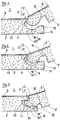
- the floor elements are provided with male joining members on a first edge, while a second edge of the floor elements is provided with a female joining member, whereby the male joining member is provided with a tongue and a lower side groove while the female joining member is provided with a groove and a cheek, the cheek being provided with a lip.
- the floor elements are intended to mainly be joined together by tilting the floor element to be joined with an already installed floor element or a row of already installed floor elements, with the male joining member of the floor element angled downwards, and the first edge is allowed to be mainly parallel to the second edge of the already installed floor element or elements.
- the tongue of the tilted floor element is inserted into the groove of the female joining member of the already installed floor element or elements, whereby the tilted floor element is turned downwards, with its lower edge as a pivot axis, so that the lip eventually snaps or falls into the lower side groove where the decorative upper layer of the floor elements are mainly parallel.
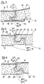
- the floor elements, on a third edge, are provided with a male vertical assembly joining member, while a fourth edge is provided with female vertical assembly joining member, the fourth edge being arranged on a side opposite to the third edge.
- the male vertical assembly joining members are provided with mainly vertical lower cheek surfaces arranged parallel to the closest edge, which lower cheek surfaces are intended to interact with mainly vertical upper cheek surfaces arranged on the female vertical assembly joining members so that two joined adjacent floor elements are locked against each other in a horizontal direction.
- Two adjacent edges of a floor element, at the same time, and in the same turning motion, can be joined with a floor element adjacent to the first edge and a floor element adjacent to the third or fourth edge.
- the male vertical assembly joining member is provided with a plurality of hooks intended to interact with matching undercuts arranged on the female vertical assembly joining member, and the snapping hooks and matching undercuts, by being provided with mainly horizontal locking surfaces, limit the vertical movement between two joined adjacent floor elements.
- the force needed to overcome the static friction along the joint between two completely assembled male and female joining members is preferably larger than 10N per meter of joint length, suitably larger than 100N per meter of joint length.
- the joint between a third and a fourth edge of two joined floor elements preferably comprises contact surfaces which are constituted by the horizontal locking surfaces of the under cuts and hooks, the mainly vertical upper cheek surfaces and lower cheek surfaces as well as upper mating surfaces.
- the joint between two joined floor elements suitably also comprises cavities.
- the flooring material including the floor boards above is most suited when installing floors where it isn't desired to use glue. It is, however, possible to use glue or twin-faced adhesive tape in order to make the installation irreversibly permanent.
- the glue or tape is then suitably applied on, or in connection to, possible cavities or faces below the upper mating surfaces.
Description
- The present invention relates to a flooring material according to the preamble of
claim 1, comprising sheet-shaped floor elements which are joined by means of joining members. Such flooring material is known fromWO 01/02669 - Prefabricated floor boards provided with tongue and groove at the edges are quite common nowadays. These can be installed by the average handy man as they are very easy to install. Such floors can, for example, be constituted of solid wood, fibre board or particle board. These are most often provided with a surface layer such as lacquer, or some kind of laminate. The boards are most often installed by being glued via tongue and groove. The most common types of tongue and groove are however burdened with the disadvantage to form gaps of varying width between the floor boards in cases where the installer hasn't been thorough enough. Dirt will easily collect in such gaps. Moisture will furthermore enter the gaps which will cause the core to expand in cases where it is made of wood, fiber board or particle board, which usually is the case. The expansion will cause the surface layer to rise closest to the edges of the joint which radically reduces the useful life of the floor since the surface layer will be exposed to an exceptional wear. Different types of tensioning devices, forcing the floor boards together during installation can be used to avoid such gaps. This operation is however more or less awkward. It is therefore desirable to achieve a joint which is self-guiding and thereby automatically finds the correct position. Such a joint would also be possible to utilize in floors where no glue is to be used.
- Such a joint is known through
WO 94/26999 - According to
WO 94/26999 -
WO 00/47841 - It is also known through
WO 97/47834 WO 94/26999 WO 97/47834 - It is, through the present invention, made possible to solve the above mentioned problems whereby a floor element which can be assembled without having to be slid along already assembled floor elements has been achieved. It is thereby made possible to achieve tighter joints.
- The invention is defined in the appended claims.
- Accordingly, the invention relates to a flooring material comprising sheet-shaped floor elements with a mainly square or rectangular shape, which floor elements are provided with edges, a lower side and an upper decorative layer, whereby the floor elements are intended to be joined by means of joining members. The floor elements are provided with male joining members on a first edge, while a second edge of the floor elements is provided with a female joining member, whereby the male joining member is provided with a tongue and a lower side groove while the female joining member is provided with a groove and a cheek, the cheek being provided with a lip. The floor elements are intended to mainly be joined together by tilting the floor element to be joined with an already installed floor element or a row of already installed floor elements, with the male joining member of the floor element angled downwards, and the first edge is allowed to be mainly parallel to the second edge of the already installed floor element or elements. The tongue of the tilted floor element is inserted into the groove of the female joining member of the already installed floor element or elements, whereby the tilted floor element is turned downwards, with its lower edge as a pivot axis, so that the lip eventually snaps or falls into the lower side groove where the decorative upper layer of the floor elements are mainly parallel.
- The floor elements, on a third edge, are provided with a male vertical assembly joining member, while a fourth edge is provided with female vertical assembly joining member, the fourth edge being arranged on a side opposite to the third edge. The male vertical assembly joining members are provided with mainly vertical lower cheek surfaces arranged parallel to the closest edge, which lower cheek surfaces are intended to interact with mainly vertical upper cheek surfaces arranged on the female vertical assembly joining members so that two joined adjacent floor elements are locked against each other in a horizontal direction. Two adjacent edges of a floor element, at the same time, and in the same turning motion, can be joined with a floor element adjacent to the first edge and a floor element adjacent to the third or fourth edge. The male vertical assembly joining member is provided with a plurality of hooks intended to interact with matching undercuts arranged on the female vertical assembly joining member, and the snapping hooks and matching undercuts, by being provided with mainly horizontal locking surfaces, limit the vertical movement between two joined adjacent floor elements.
- The force needed to overcome the static friction along the joint between two completely assembled male and female joining members is preferably larger than 10N per meter of joint length, suitably larger than 100N per meter of joint length.
- The joint between a third and a fourth edge of two joined floor elements preferably comprises contact surfaces which are constituted by the horizontal locking surfaces of the under cuts and hooks, the mainly vertical upper cheek surfaces and lower cheek surfaces as well as upper mating surfaces.
- The joint between two joined floor elements suitably also comprises cavities.
- The flooring material including the floor boards above is most suited when installing floors where it isn't desired to use glue. It is, however, possible to use glue or twin-faced adhesive tape in order to make the installation irreversibly permanent. The glue or tape is then suitably applied on, or in connection to, possible cavities or faces below the upper mating surfaces.
- The invention is described further in connection to enclosed figures showing different embodiments of a flooring material whereby,
-
figure 1 shows, in cross-section, a first and asecond edge -
figure 2 shows, in cross-section, a second embodiment of a first and asecond edge -
figure 3 shows, in cross-section, a third embodiment of a first and asecond edge -
figure 4 shows, in cross-section, a fourth embodiment of a first and asecond edge -
figure 5 shows, in cross-section, a third and afourth edge -
figure 6 shows, in cross-section, a second embodiment of a third and afourth edge -
figure 7 shows, in cross-section, a third embodiment of a third and afourth edge -
figure 8 shows, in cross-section, a fourth embodiment of a third and afourth edge assembly joining profile 30, during joining.
Accordingly
The embodiment shown in
The embodiment shown in
The embodiment shown in
The male vertical
The joint between a third and a
The joint between two joined
The embodiment shown in
The embodiment shown in
The embodiment shown in
The female vertical
Two
The
The invention is not limited by the embodiments shown since they can be varied within the scope of the invention as defined in the appended claims.
Claims (7)
- Flooring material comprising sheet-shaped floor elements (1) with a mainly square or rectangular shape, which floor elements (1) are provided with edges (2), a lower side (5) and an upper decorative layer (3), whereby the floor elements (1) are intended to be joined by means of joining members (10), wherein- the floor elements (1) are provided with male joining members (10I) on a first edge (2I), while a second edge (2II) of the floor elements (1) is provided with a female joining member (10II), whereby the male joining member (10I) is provided with a tongue (11) and a lower side (5) groove (12) while the female joining member (10II) is provided with a groove (13) and a cheek (14), the cheek (14) being provided with a lip (15), whereby the floor elements (1) are intended to mainly be joined together by tilting the floor element (1) to be joined with an already installed floor element (1) or a row of already installed floor elements (1), with the male joining member (10I) of the floor element (1) angled downwards, and that the first edge (2I) is allowed to be mainly parallel to the second edge (2II) of the already installed floor element (1) or elements (1), whereby the tongue (11) of the tilted floor element (1) is inserted into the groove (13) of the female joining member (10II) of the already installed floor element (1) or elements (1), whereby the tilted floor element (1) is turned downwards, with its lower edge as a pivot axis, so that the lip (15) eventually snaps or falls into the lower side (5) groove (12) where the decorative upper layer (3) of the floor elements (1) are mainly parallel;- the floor elements (1), on a third edge (2III), are provided with a male vertical assembly joining member (10III), while a fourth edge (2IV) is provided with female vertical assembly joining member (10IV), the fourth edge (2IV) being arranged on a side opposite to the third edge (2III), wherein the male vertical assembly joining members (10III) are provided with mainly vertical lower cheek surfaces (21) arranged parallel to the closest edge (2), which lower cheek surfaces (21) are intended to interact with mainly vertical upper cheek surfaces (22) arranged on the female vertical assembly joining members so that two joined adjacent floor elements (1) are locked against each other in a horizontal direction, and- two adjacent edges (2) of a floor element (1), at the same time, and in the same turning motion, can be joined with a floor element (1) adjacent to the first edge (2I) and a floor element adjacent to the third or fourth edge (2III and 2IV, respectively), characterized in that the male vertical assembly joining member (10III) is provided with a plurality of snapping hooks (23) intended to interact with matching undercuts (24) arranged on the female vertical assembly joining member, (10IV) and in that said snapping hooks (23) and matching undercuts (24), by being provided with mainly horizontal locking surfaces, limit the vertical movement between two joined adjacent floor elements (1).
- Floor material according to claim 1, characterized in that the joint between a third and a fourth edge (2III and 2IV respectively) of two joined floor elements (1) comprises contact surfaces which are constituted by the mainly horizontal locking surfaces of the undercuts (24) and hooks (23), the mainly vertical upper cheek surfaces (22) and lower cheek surfaces as well as upper mating surfaces (25).
- Floor material according to any of the preceding claims, characterized in that said floor elements comprise a core material and that said hooks (23) and undercuts (24) are formed in the material of the core.
- Floor material according to any of the preceding claims, characterized in that a lower side (5) recess is formed at said fourth edge (2IV) so that the bottom side of said lower cheek (21) is recessed from said lower side (5).
- Flooring material according to any of the preceding claims, characterized in that the force needed to overcome the static friction along the joint between two completely assembled male and female joining members (10I and 10II respectively) is larger than 10N per meter of joint length, preferably larger than 100N per meter of joint length.
- Flooring material according to any of the preceding claims, characterized in that the joint between two joined floor elements (1) also comprises cavities (6).
- Flooring material according to any of the preceding claims, characterized in that the floor elements (1) have a core comprised of particles or fiber of wood bonded with resin or glue.
Applications Claiming Priority (3)
| Application Number | Priority Date | Filing Date | Title |
|---|---|---|---|
| SE0001149A SE518184C2 (en) | 2000-03-31 | 2000-03-31 | Floor covering material comprising disc-shaped floor elements which are joined together by means of interconnecting means |
| EP08166656.2A EP2009195B1 (en) | 2000-03-31 | 2001-02-14 | A flooring material comprising sheet-shaped floor elements which are joined by means of joining members |
| EP01906461A EP1276941B1 (en) | 2000-03-31 | 2001-02-14 | A flooring material comprising sheet-shaped floor elements which are joinable by means of joining members |
Related Parent Applications (3)
| Application Number | Title | Priority Date | Filing Date |
|---|---|---|---|
| EP01906461A Division EP1276941B1 (en) | 2000-03-31 | 2001-02-14 | A flooring material comprising sheet-shaped floor elements which are joinable by means of joining members |
| EP08166656.2A Division EP2009195B1 (en) | 2000-03-31 | 2001-02-14 | A flooring material comprising sheet-shaped floor elements which are joined by means of joining members |
| EP08166656.2A Division-Into EP2009195B1 (en) | 2000-03-31 | 2001-02-14 | A flooring material comprising sheet-shaped floor elements which are joined by means of joining members |
Publications (3)
| Publication Number | Publication Date |
|---|---|
| EP2813636A2 EP2813636A2 (en) | 2014-12-17 |
| EP2813636A3 EP2813636A3 (en) | 2015-03-25 |
| EP2813636B1 true EP2813636B1 (en) | 2017-12-27 |
Family
ID=51867945
Family Applications (8)
| Application Number | Title | Priority Date | Filing Date |
|---|---|---|---|
| EP14169350.7A Expired - Lifetime EP2813637B1 (en) | 2000-03-31 | 2001-02-14 | A flooring material of sheet-shaped floor elements joined with joining members. |
| EP14169293.9A Ceased EP2813635A3 (en) | 2000-03-31 | 2001-02-14 | A flooring material of sheet-shaped floor elements joined with joining members. |
| EP14169440.6A Withdrawn EP2813640A3 (en) | 2000-03-31 | 2001-02-14 | A flooring material of sheet-shaped floor elements joined with joining members |
| EP14169158.4A Expired - Lifetime EP2813634B1 (en) | 2000-03-31 | 2001-02-14 | A flooring material of sheet-shaped floor elements joined with joining members |
| EP14169472.9A Withdrawn EP2813641A3 (en) | 2000-03-31 | 2001-02-14 | Method for installing a flooring material of sheet-shaped floor elements |
| EP14169399.4A Expired - Lifetime EP2813638B1 (en) | 2000-03-31 | 2001-02-14 | A flooring material of sheet-shaped floor elements joined with joining members |
| EP14169330.9A Expired - Lifetime EP2813636B1 (en) | 2000-03-31 | 2001-02-14 | A flooring material of sheet-shaped floor elements joined with joining members. |
| EP14169430.7A Expired - Lifetime EP2813639B1 (en) | 2000-03-31 | 2001-02-14 | A flooring material of sheet-shaped floor elements joined with joining members |
Family Applications Before (6)
| Application Number | Title | Priority Date | Filing Date |
|---|---|---|---|
| EP14169350.7A Expired - Lifetime EP2813637B1 (en) | 2000-03-31 | 2001-02-14 | A flooring material of sheet-shaped floor elements joined with joining members. |
| EP14169293.9A Ceased EP2813635A3 (en) | 2000-03-31 | 2001-02-14 | A flooring material of sheet-shaped floor elements joined with joining members. |
| EP14169440.6A Withdrawn EP2813640A3 (en) | 2000-03-31 | 2001-02-14 | A flooring material of sheet-shaped floor elements joined with joining members |
| EP14169158.4A Expired - Lifetime EP2813634B1 (en) | 2000-03-31 | 2001-02-14 | A flooring material of sheet-shaped floor elements joined with joining members |
| EP14169472.9A Withdrawn EP2813641A3 (en) | 2000-03-31 | 2001-02-14 | Method for installing a flooring material of sheet-shaped floor elements |
| EP14169399.4A Expired - Lifetime EP2813638B1 (en) | 2000-03-31 | 2001-02-14 | A flooring material of sheet-shaped floor elements joined with joining members |
Family Applications After (1)
| Application Number | Title | Priority Date | Filing Date |
|---|---|---|---|
| EP14169430.7A Expired - Lifetime EP2813639B1 (en) | 2000-03-31 | 2001-02-14 | A flooring material of sheet-shaped floor elements joined with joining members |
Country Status (5)
| Country | Link |
|---|---|
| EP (8) | EP2813637B1 (en) |
| DE (6) | DE14169132T1 (en) |
| DK (1) | DK2009195T3 (en) |
| ES (5) | ES2523115T1 (en) |
| PT (1) | PT2009195E (en) |
Families Citing this family (1)
| Publication number | Priority date | Publication date | Assignee | Title |
|---|---|---|---|---|
| FR3089534B1 (en) * | 2018-12-07 | 2023-03-03 | Gerflor | PANEL WITH VERTICAL ASSEMBLY FOR THE REALIZATION OF A CLADDING |
Family Cites Families (8)
| Publication number | Priority date | Publication date | Assignee | Title |
|---|---|---|---|---|
| DE2238660A1 (en) * | 1972-08-05 | 1974-02-07 | Heinrich Hebgen | FORMAL JOINT CONNECTION OF PANEL-SHAPED COMPONENTS WITHOUT SEPARATE CONNECTING ELEMENTS |
| SE9301595L (en) * | 1993-05-10 | 1994-10-17 | Tony Pervan | Grout for thin liquid hard floors |
| BE1010487A6 (en) | 1996-06-11 | 1998-10-06 | Unilin Beheer Bv | FLOOR COATING CONSISTING OF HARD FLOOR PANELS AND METHOD FOR MANUFACTURING SUCH FLOOR PANELS. |
| SE512290C2 (en) * | 1998-06-03 | 2000-02-28 | Valinge Aluminium Ab | Locking system for mechanical joining of floorboards and floorboard provided with the locking system |
| SE515789C2 (en) * | 1999-02-10 | 2001-10-08 | Perstorp Flooring Ab | Floor covering material comprising floor elements which are intended to be joined vertically |
| IT1311220B1 (en) * | 1999-04-20 | 2002-03-04 | Patt Srl | SLAT FLOOR AND METHOD FOR ITS INSTALLATION |
| EP2312087B1 (en) * | 1999-06-30 | 2018-03-28 | Akzenta Paneele + Profile GmbH | Panel fastening system and panel with fastening system |
| DE10001076C1 (en) * | 2000-01-13 | 2001-10-04 | Huelsta Werke Huels Kg | Panel element to construct floor covering; has groove and spring on opposite longitudinal sides and has groove and tongue on opposite end faces, to connect and secure adjacent panel elements |
-
2001
- 2001-02-14 ES ES13160294.8T patent/ES2523115T1/en active Pending
- 2001-02-14 DE DE14169132.9T patent/DE14169132T1/en active Pending
- 2001-02-14 ES ES14169158.4T patent/ES2646014T3/en not_active Expired - Lifetime
- 2001-02-14 PT PT81666562T patent/PT2009195E/en unknown
- 2001-02-14 EP EP14169350.7A patent/EP2813637B1/en not_active Expired - Lifetime
- 2001-02-14 EP EP14169293.9A patent/EP2813635A3/en not_active Ceased
- 2001-02-14 DE DE14169350.7T patent/DE14169350T1/en active Pending
- 2001-02-14 EP EP14169440.6A patent/EP2813640A3/en not_active Withdrawn
- 2001-02-14 ES ES14169330.9T patent/ES2660502T3/en not_active Expired - Lifetime
- 2001-02-14 EP EP14169158.4A patent/EP2813634B1/en not_active Expired - Lifetime
- 2001-02-14 DE DE14169472.9T patent/DE14169472T1/en active Pending
- 2001-02-14 EP EP14169472.9A patent/EP2813641A3/en not_active Withdrawn
- 2001-02-14 DK DK08166656.2T patent/DK2009195T3/en active
- 2001-02-14 DE DE14169158.4T patent/DE14169158T1/en active Pending
- 2001-02-14 EP EP14169399.4A patent/EP2813638B1/en not_active Expired - Lifetime
- 2001-02-14 ES ES14169430T patent/ES2769548T3/en not_active Expired - Lifetime
- 2001-02-14 ES ES08166656.2T patent/ES2543164T3/en not_active Expired - Lifetime
- 2001-02-14 DE DE13160294.8T patent/DE13160294T1/en active Pending
- 2001-02-14 EP EP14169330.9A patent/EP2813636B1/en not_active Expired - Lifetime
- 2001-02-14 DE DE08166656.2T patent/DE08166656T1/en active Pending
- 2001-02-14 EP EP14169430.7A patent/EP2813639B1/en not_active Expired - Lifetime
Non-Patent Citations (1)
| Title |
|---|
| None * |
Also Published As
| Publication number | Publication date |
|---|---|
| EP2813638A3 (en) | 2015-09-02 |
| EP2813637A3 (en) | 2015-09-02 |
| DE14169472T1 (en) | 2015-06-11 |
| EP2813639A2 (en) | 2014-12-17 |
| DE14169158T1 (en) | 2015-06-11 |
| EP2813639B1 (en) | 2019-11-13 |
| EP2813638B1 (en) | 2020-04-08 |
| ES2523115T1 (en) | 2014-11-21 |
| EP2813640A3 (en) | 2015-09-02 |
| DE14169132T1 (en) | 2015-06-03 |
| DE13160294T1 (en) | 2015-01-08 |
| DE08166656T1 (en) | 2015-04-02 |
| PT2009195E (en) | 2015-09-14 |
| ES2543164T3 (en) | 2015-08-17 |
| EP2813634A3 (en) | 2015-03-25 |
| EP2813634B1 (en) | 2017-08-16 |
| EP2813635A2 (en) | 2014-12-17 |
| EP2813637B1 (en) | 2020-04-08 |
| ES2646014T3 (en) | 2017-12-11 |
| EP2813640A2 (en) | 2014-12-17 |
| EP2813637A2 (en) | 2014-12-17 |
| ES2769548T3 (en) | 2020-06-26 |
| EP2813636A3 (en) | 2015-03-25 |
| ES2660502T3 (en) | 2018-03-22 |
| EP2813641A3 (en) | 2016-04-06 |
| EP2813641A2 (en) | 2014-12-17 |
| EP2813638A2 (en) | 2014-12-17 |
| EP2813635A3 (en) | 2015-03-25 |
| DK2009195T3 (en) | 2015-06-22 |
| EP2813639A3 (en) | 2015-09-02 |
| EP2813634A2 (en) | 2014-12-17 |
| DE14169350T1 (en) | 2015-06-03 |
| EP2813636A2 (en) | 2014-12-17 |
Similar Documents
| Publication | Publication Date | Title |
|---|---|---|
| EP1276941B1 (en) | A flooring material comprising sheet-shaped floor elements which are joinable by means of joining members | |
| AU2001234285A1 (en) | A flooring material comprising sheet-shaped floor elements which are joined by means of joining members | |
| EP2813636B1 (en) | A flooring material of sheet-shaped floor elements joined with joining members. |
Legal Events
| Date | Code | Title | Description |
|---|---|---|---|
| 17P | Request for examination filed |
Effective date: 20140521 |
|
| AC | Divisional application: reference to earlier application |
Ref document number: 2009195 Country of ref document: EP Kind code of ref document: P Ref document number: 1276941 Country of ref document: EP Kind code of ref document: P |
|
| AK | Designated contracting states |
Kind code of ref document: A2 Designated state(s): AT BE CH CY DE DK ES FI FR GB GR IE IT LI LU MC NL PT SE TR |
|
| AX | Request for extension of the european patent |
Extension state: LT LV RO |
|
| PUAI | Public reference made under article 153(3) epc to a published international application that has entered the european phase |
Free format text: ORIGINAL CODE: 0009012 |
|
| PUAL | Search report despatched |
Free format text: ORIGINAL CODE: 0009013 |
|
| AK | Designated contracting states |
Kind code of ref document: A3 Designated state(s): AT BE CH CY DE DK ES FI FR GB GR IE IT LI LU MC NL PT SE TR |
|
| AX | Request for extension of the european patent |
Extension state: LT LV RO |
|
| RIC1 | Information provided on ipc code assigned before grant |
Ipc: E04F 15/04 20060101ALN20150219BHEP Ipc: E04F 15/02 20060101AFI20150219BHEP |
|
| R17P | Request for examination filed (corrected) |
Effective date: 20150424 |
|
| RAX | Requested extension states of the european patent have changed |
Extension state: LV Payment date: 20150424 Extension state: LT Payment date: 20150424 Extension state: RO Payment date: 20150424 |
|
| RBV | Designated contracting states (corrected) |
Designated state(s): AT BE CH CY DE DK ES FI FR GB GR IE IT LI LU MC NL PT SE TR |
|
| GRAP | Despatch of communication of intention to grant a patent |
Free format text: ORIGINAL CODE: EPIDOSNIGR1 |
|
| RIC1 | Information provided on ipc code assigned before grant |
Ipc: E04F 15/02 20060101AFI20170131BHEP Ipc: E04F 15/04 20060101ALN20170131BHEP |
|
| INTG | Intention to grant announced |
Effective date: 20170301 |
|
| GRAJ | Information related to disapproval of communication of intention to grant by the applicant or resumption of examination proceedings by the epo deleted |
Free format text: ORIGINAL CODE: EPIDOSDIGR1 |
|
| INTC | Intention to grant announced (deleted) | ||
| GRAP | Despatch of communication of intention to grant a patent |
Free format text: ORIGINAL CODE: EPIDOSNIGR1 |
|
| RIC1 | Information provided on ipc code assigned before grant |
Ipc: E04F 15/04 20060101ALN20170712BHEP Ipc: E04F 15/02 20060101AFI20170712BHEP |
|
| INTG | Intention to grant announced |
Effective date: 20170817 |
|
| GRAS | Grant fee paid |
Free format text: ORIGINAL CODE: EPIDOSNIGR3 |
|
| GRAA | (expected) grant |
Free format text: ORIGINAL CODE: 0009210 |
|
| AC | Divisional application: reference to earlier application |
Ref document number: 2009195 Country of ref document: EP Kind code of ref document: P Ref document number: 1276941 Country of ref document: EP Kind code of ref document: P |
|
| AK | Designated contracting states |
Kind code of ref document: B1 Designated state(s): AT BE CH CY DE DK ES FI FR GB GR IE IT LI LU MC NL PT SE TR |
|
| AX | Request for extension of the european patent |
Extension state: LT LV RO |
|
| REG | Reference to a national code |
Ref country code: GB Ref legal event code: FG4D |
|
| REG | Reference to a national code |
Ref country code: CH Ref legal event code: EP |
|
| REG | Reference to a national code |
Ref country code: AT Ref legal event code: REF Ref document number: 958432 Country of ref document: AT Kind code of ref document: T Effective date: 20180115 |
|
| REG | Reference to a national code |
Ref country code: IE Ref legal event code: FG4D |
|
| REG | Reference to a national code |
Ref country code: DE Ref legal event code: R096 Ref document number: 60150723 Country of ref document: DE |
|
| REG | Reference to a national code |
Ref country code: FR Ref legal event code: PLFP Year of fee payment: 18 |
|
| REG | Reference to a national code |
Ref country code: ES Ref legal event code: FG2A Ref document number: 2660502 Country of ref document: ES Kind code of ref document: T3 Effective date: 20180322 |
|
| PG25 | Lapsed in a contracting state [announced via postgrant information from national office to epo] |
Ref country code: FI Free format text: LAPSE BECAUSE OF FAILURE TO SUBMIT A TRANSLATION OF THE DESCRIPTION OR TO PAY THE FEE WITHIN THE PRESCRIBED TIME-LIMIT Effective date: 20171227 |
|
| REG | Reference to a national code |
Ref country code: NL Ref legal event code: MP Effective date: 20171227 |
|
| REG | Reference to a national code |
Ref country code: LT Ref legal event code: MG9D |
|
| REG | Reference to a national code |
Ref country code: AT Ref legal event code: MK05 Ref document number: 958432 Country of ref document: AT Kind code of ref document: T Effective date: 20171227 |
|
| PG25 | Lapsed in a contracting state [announced via postgrant information from national office to epo] |
Ref country code: GR Free format text: LAPSE BECAUSE OF FAILURE TO SUBMIT A TRANSLATION OF THE DESCRIPTION OR TO PAY THE FEE WITHIN THE PRESCRIBED TIME-LIMIT Effective date: 20180328 |
|
| PG25 | Lapsed in a contracting state [announced via postgrant information from national office to epo] |
Ref country code: NL Free format text: LAPSE BECAUSE OF FAILURE TO SUBMIT A TRANSLATION OF THE DESCRIPTION OR TO PAY THE FEE WITHIN THE PRESCRIBED TIME-LIMIT Effective date: 20171227 |
|
| PG25 | Lapsed in a contracting state [announced via postgrant information from national office to epo] |
Ref country code: CY Free format text: LAPSE BECAUSE OF FAILURE TO SUBMIT A TRANSLATION OF THE DESCRIPTION OR TO PAY THE FEE WITHIN THE PRESCRIBED TIME-LIMIT Effective date: 20171227 |
|
| PG25 | Lapsed in a contracting state [announced via postgrant information from national office to epo] |
Ref country code: AT Free format text: LAPSE BECAUSE OF FAILURE TO SUBMIT A TRANSLATION OF THE DESCRIPTION OR TO PAY THE FEE WITHIN THE PRESCRIBED TIME-LIMIT Effective date: 20171227 Ref country code: IT Free format text: LAPSE BECAUSE OF FAILURE TO SUBMIT A TRANSLATION OF THE DESCRIPTION OR TO PAY THE FEE WITHIN THE PRESCRIBED TIME-LIMIT Effective date: 20171227 |
|
| REG | Reference to a national code |
Ref country code: CH Ref legal event code: PL |
|
| PG25 | Lapsed in a contracting state [announced via postgrant information from national office to epo] |
Ref country code: MC Free format text: LAPSE BECAUSE OF FAILURE TO SUBMIT A TRANSLATION OF THE DESCRIPTION OR TO PAY THE FEE WITHIN THE PRESCRIBED TIME-LIMIT Effective date: 20171227 |
|
| REG | Reference to a national code |
Ref country code: DE Ref legal event code: R097 Ref document number: 60150723 Country of ref document: DE |
|
| PLBE | No opposition filed within time limit |
Free format text: ORIGINAL CODE: 0009261 |
|
| STAA | Information on the status of an ep patent application or granted ep patent |
Free format text: STATUS: NO OPPOSITION FILED WITHIN TIME LIMIT |
|
| REG | Reference to a national code |
Ref country code: IE Ref legal event code: MM4A |
|
| REG | Reference to a national code |
Ref country code: BE Ref legal event code: MM Effective date: 20180228 |
|
| PG25 | Lapsed in a contracting state [announced via postgrant information from national office to epo] |
Ref country code: LU Free format text: LAPSE BECAUSE OF NON-PAYMENT OF DUE FEES Effective date: 20180214 Ref country code: DK Free format text: LAPSE BECAUSE OF FAILURE TO SUBMIT A TRANSLATION OF THE DESCRIPTION OR TO PAY THE FEE WITHIN THE PRESCRIBED TIME-LIMIT Effective date: 20171227 Ref country code: LI Free format text: LAPSE BECAUSE OF NON-PAYMENT OF DUE FEES Effective date: 20180228 Ref country code: CH Free format text: LAPSE BECAUSE OF NON-PAYMENT OF DUE FEES Effective date: 20180228 |
|
| 26N | No opposition filed |
Effective date: 20180928 |
|
| PG25 | Lapsed in a contracting state [announced via postgrant information from national office to epo] |
Ref country code: IE Free format text: LAPSE BECAUSE OF NON-PAYMENT OF DUE FEES Effective date: 20180214 |
|
| PG25 | Lapsed in a contracting state [announced via postgrant information from national office to epo] |
Ref country code: BE Free format text: LAPSE BECAUSE OF NON-PAYMENT OF DUE FEES Effective date: 20180228 |
|
| REG | Reference to a national code |
Ref country code: ES Ref legal event code: PC2A Owner name: UNILIN NORDIC AB Effective date: 20200130 |
|
| REG | Reference to a national code |
Ref country code: DE Ref legal event code: R082 Ref document number: 60150723 Country of ref document: DE Representative=s name: MANITZ FINSTERWALD PATENT- UND RECHTSANWALTSPA, DE Ref country code: DE Ref legal event code: R081 Ref document number: 60150723 Country of ref document: DE Owner name: UNILIN NORDIC AB, SE Free format text: FORMER OWNER: PERGO (EUROPE) AB, TRELLEBORG, SE |
|
| PGFP | Annual fee paid to national office [announced via postgrant information from national office to epo] |
Ref country code: ES Payment date: 20200302 Year of fee payment: 20 Ref country code: DE Payment date: 20200227 Year of fee payment: 20 Ref country code: GB Payment date: 20200227 Year of fee payment: 20 |
|
| PG25 | Lapsed in a contracting state [announced via postgrant information from national office to epo] |
Ref country code: PT Free format text: LAPSE BECAUSE OF FAILURE TO SUBMIT A TRANSLATION OF THE DESCRIPTION OR TO PAY THE FEE WITHIN THE PRESCRIBED TIME-LIMIT Effective date: 20171227 |
|
| PG25 | Lapsed in a contracting state [announced via postgrant information from national office to epo] |
Ref country code: SE Free format text: LAPSE BECAUSE OF FAILURE TO SUBMIT A TRANSLATION OF THE DESCRIPTION OR TO PAY THE FEE WITHIN THE PRESCRIBED TIME-LIMIT Effective date: 20171227 |
|
| PGFP | Annual fee paid to national office [announced via postgrant information from national office to epo] |
Ref country code: TR Payment date: 20200128 Year of fee payment: 20 Ref country code: FR Payment date: 20200225 Year of fee payment: 20 |
|
| REG | Reference to a national code |
Ref country code: DE Ref legal event code: R071 Ref document number: 60150723 Country of ref document: DE |
|
| REG | Reference to a national code |
Ref country code: GB Ref legal event code: PE20 Expiry date: 20210213 |
|
| PG25 | Lapsed in a contracting state [announced via postgrant information from national office to epo] |
Ref country code: GB Free format text: LAPSE BECAUSE OF EXPIRATION OF PROTECTION Effective date: 20210213 |
|
| REG | Reference to a national code |
Ref country code: ES Ref legal event code: FD2A Effective date: 20220128 |
|
| PG25 | Lapsed in a contracting state [announced via postgrant information from national office to epo] |
Ref country code: ES Free format text: LAPSE BECAUSE OF EXPIRATION OF PROTECTION Effective date: 20210215 |
|
| PG25 | Lapsed in a contracting state [announced via postgrant information from national office to epo] |
Ref country code: TR Free format text: LAPSE BECAUSE OF NON-PAYMENT OF DUE FEES Effective date: 20210214 |