EP2813412A1 - Connection mechanism and infant care equipment having the connection mechanism - Google Patents
Connection mechanism and infant care equipment having the connection mechanism Download PDFInfo
- Publication number
- EP2813412A1 EP2813412A1 EP14171886.6A EP14171886A EP2813412A1 EP 2813412 A1 EP2813412 A1 EP 2813412A1 EP 14171886 A EP14171886 A EP 14171886A EP 2813412 A1 EP2813412 A1 EP 2813412A1
- Authority
- EP
- European Patent Office
- Prior art keywords
- base
- latch
- connection mechanism
- operating
- operating part
- Prior art date
- Legal status (The legal status is an assumption and is not a legal conclusion. Google has not performed a legal analysis and makes no representation as to the accuracy of the status listed.)
- Granted
Links
Images


Classifications
-
- B—PERFORMING OPERATIONS; TRANSPORTING
- B62—LAND VEHICLES FOR TRAVELLING OTHERWISE THAN ON RAILS
- B62B—HAND-PROPELLED VEHICLES, e.g. HAND CARTS OR PERAMBULATORS; SLEDGES
- B62B7/00—Carriages for children; Perambulators, e.g. dolls' perambulators
- B62B7/04—Carriages for children; Perambulators, e.g. dolls' perambulators having more than one wheel axis; Steering devices therefor
- B62B7/14—Carriages for children; Perambulators, e.g. dolls' perambulators having more than one wheel axis; Steering devices therefor with detachable or rotatably-mounted body
- B62B7/142—Means for securing the body to the frame
-
- B—PERFORMING OPERATIONS; TRANSPORTING
- B60—VEHICLES IN GENERAL
- B60N—SEATS SPECIALLY ADAPTED FOR VEHICLES; VEHICLE PASSENGER ACCOMMODATION NOT OTHERWISE PROVIDED FOR
- B60N2/00—Seats specially adapted for vehicles; Arrangement or mounting of seats in vehicles
- B60N2/24—Seats specially adapted for vehicles; Arrangement or mounting of seats in vehicles for particular purposes or particular vehicles
- B60N2/26—Seats specially adapted for vehicles; Arrangement or mounting of seats in vehicles for particular purposes or particular vehicles for children
- B60N2/28—Seats readily mountable on, and dismountable from, existing seats or other parts of the vehicle
-
- B—PERFORMING OPERATIONS; TRANSPORTING
- B62—LAND VEHICLES FOR TRAVELLING OTHERWISE THAN ON RAILS
- B62B—HAND-PROPELLED VEHICLES, e.g. HAND CARTS OR PERAMBULATORS; SLEDGES
- B62B2205/00—Hand-propelled vehicles or sledges being foldable or dismountable when not in use
- B62B2205/20—Catches; Locking or releasing an articulation
- B62B2205/22—Catches; Locking or releasing an articulation remotely controlled, e.g. from the handlebar
-
- B—PERFORMING OPERATIONS; TRANSPORTING
- B62—LAND VEHICLES FOR TRAVELLING OTHERWISE THAN ON RAILS
- B62B—HAND-PROPELLED VEHICLES, e.g. HAND CARTS OR PERAMBULATORS; SLEDGES
- B62B2205/00—Hand-propelled vehicles or sledges being foldable or dismountable when not in use
- B62B2205/20—Catches; Locking or releasing an articulation
- B62B2205/24—Catches; Locking or releasing an articulation to hold in the folded position
-
- Y—GENERAL TAGGING OF NEW TECHNOLOGICAL DEVELOPMENTS; GENERAL TAGGING OF CROSS-SECTIONAL TECHNOLOGIES SPANNING OVER SEVERAL SECTIONS OF THE IPC; TECHNICAL SUBJECTS COVERED BY FORMER USPC CROSS-REFERENCE ART COLLECTIONS [XRACs] AND DIGESTS
- Y10—TECHNICAL SUBJECTS COVERED BY FORMER USPC
- Y10T—TECHNICAL SUBJECTS COVERED BY FORMER US CLASSIFICATION
- Y10T403/00—Joints and connections
- Y10T403/59—Manually releaseable latch type
- Y10T403/591—Manually releaseable latch type having operating mechanism
- Y10T403/593—Remotely actuated
-
- Y—GENERAL TAGGING OF NEW TECHNOLOGICAL DEVELOPMENTS; GENERAL TAGGING OF CROSS-SECTIONAL TECHNOLOGIES SPANNING OVER SEVERAL SECTIONS OF THE IPC; TECHNICAL SUBJECTS COVERED BY FORMER USPC CROSS-REFERENCE ART COLLECTIONS [XRACs] AND DIGESTS
- Y10—TECHNICAL SUBJECTS COVERED BY FORMER USPC
- Y10T—TECHNICAL SUBJECTS COVERED BY FORMER US CLASSIFICATION
- Y10T403/00—Joints and connections
- Y10T403/59—Manually releaseable latch type
- Y10T403/599—Spring biased manipulator
-
- Y—GENERAL TAGGING OF NEW TECHNOLOGICAL DEVELOPMENTS; GENERAL TAGGING OF CROSS-SECTIONAL TECHNOLOGIES SPANNING OVER SEVERAL SECTIONS OF THE IPC; TECHNICAL SUBJECTS COVERED BY FORMER USPC CROSS-REFERENCE ART COLLECTIONS [XRACs] AND DIGESTS
- Y10—TECHNICAL SUBJECTS COVERED BY FORMER USPC
- Y10T—TECHNICAL SUBJECTS COVERED BY FORMER US CLASSIFICATION
- Y10T403/00—Joints and connections
- Y10T403/60—Biased catch or latch
- Y10T403/602—Biased catch or latch by separate spring
Definitions
- the invention relates to a connection mechanism and an infant care equipment according to the pre-characterizing clauses of claims 1 and 20.
- An infant stroller is an infant carrier designed for people to carry infants conveniently.
- Various infant strollers are available on the market.
- Most strollers are designed in foldable structures. These strollers provide much convenience to users when going out with infants.
- the stroller is provided with a seat for sitting an infant thereon.
- the seat is fixed on the stroller frame and not detachable or adjustable.
- Such design cannot satisfy customers' requirements.
- these seats are not so comfortable and cannot offer infants better sleeping conditions. Therefore, such seat design has a certain limitation.
- people also design some infant strollers having a crib for infants to sleep thereon.
- the above two kinds of infant strollers can be used cooperatively in different conditions for infants, but using several infant strollers is uneconomical and brings much loading to normal families.
- cribs In addition to the infant strollers, the above problems also appear on cribs, high chairs, infant safety seats and other infant carriers.
- a crib its crib body is usually fixedly connected to its frame, so the crib body cannot be detached alone when the crib body needs to be replaced.
- an infant safety seat its main body is fixedly connected to its base, so the main body and the base cannot be departed conveniently when the infant safety seat is required to be used forward or backward, leading to much inconvenience in daily use.
- connection mechanism which provides convenient installation and detachment and firm connection and is reliable and safe in use, and an infant care equipment having the connection mechanism.
- connection mechanism for detachably installing a carrier device to a supporting device and includes two bases, a latch, and an operating component.
- the two bases are fixed on the supporting device and the carrier device respectively.
- the two bases are detachably connected with each other.
- the latch and the operating component are disposed on one of the base.
- the operating component is operably connected to the latch. The operating component selectively drives the latch to move to a locking position so that the two bases are locked with each other, or drives the latch to move to an unlocking position so that the two bases are unlocked from each other.
- FIG. 1 and FIG. 2 illustrate an infant care equipment 200 according to the invention.
- the infant care equipment 200 is an infant stroller but not limited thereto.
- the infant care equipment 200 includes a carrier device 201, a supporting device 202, and two connection mechanisms 100.
- the connection mechanism 100 is used for detachably installing the carrier device 201 to the supporting device 202.
- the connection mechanisms 100 are disposed symmetrically at two sides of each of the carrier device 201 and the supporting device 202.
- the carrier device 201 can be installed forwards or backwards on the supporting device 202.
- the connection mechanism 100 includes a first base 1, a second base 2, a latch 3, and an operating component 400.
- the first base 1 is fixed on the supporting device 202.
- the second base 2 is fixed on the carrier device 201 and detachably connected to the first base 1.
- the latch 3 is movably disposed on the second base 2 and corresponds to the first base 1.
- the operating component 400 is disposed on the second base 2 and operably connected to the latch 3. The operating component 400 selectively drives the latch 3 to move to a locking position so that the second base 2 is locked to the first base 1, or drives the latch 3 to move to an unlocking position so that the second base 2 is unlocked from the first base 1.
- the connection mechanism 100 of the embodiment includes the first base 1, the second base 2, the latch 3, and the operating component 400.
- the first base 1 includes a first base body 11 and a blocking part 12.
- the first base body 11 has a recess 111.
- the blocking part 12 is formed on an inner side wall of the recess 111.
- the second base 2 includes a second base body 21 and a protrusive block 22.
- the protrusive block 22 is formed on the second base body 21 and detachably accommodated in the recess 111.
- the protrusive block 22 has a first sliding slot 221 and a second sliding slot 222.
- the latch 3 is slidably disposed in the first sliding slot 221.
- the latch 3 has a guiding portion 31 corresponding to the blocking part 12 in the installation direction.
- the guiding portion 31 shrinks gradually in a direction toward the locking position.
- the bottom surface of the guiding portion 31 is an oblique surface.
- the second base 2 slides downward during the engagement of the second base 2 with the first base 1, so the disposition of the guiding portion 31 makes the latch 3 interact with the blocking part 12 during the locking of the latch 3, so that the latch 3 can automatically retract into the first sliding slot 221 during the downward sliding of the second base 2.
- the protrusive block 22 of the second base 2 can be totally engaged in the recess 111 of the first base 1 smoothly.
- the structure is simple; the operating is convenient.
- the operating component 400 includes a first operating part 4, a second operating part 5, a transmission part 6, and a first elastic part 7.
- the first operating part 4 includes a first operating body 410.
- the first operating body 410 of the first operating part 4 is movably disposed on a first portion of the second base 2 and connected to the latch 3.
- the first operating body 410 of the first operating part 4 selectively drives the latch 3 to move to the locking position, or drives the latch 3 to move to the unlocking position.
- the guiding portion 31 of the latch 3 protrudes outside the protrusive block 22 and abuts against the blocking part 12.
- the first operating part 4 has a first slanted slot 41 having a first inclined surface 411; that is, the first operating body 410 of the first operating part 4 has the first slanted slot 41 having the first inclined surface 411.
- the extension direction of the first slanted slot 41 slants to the movement direction of the first operating part 4.
- the first inclined surface 411 is driven to abut against the latch 3 so that the movement direction of the first operating body 410 of the first operating part 4 crosses with the movement direction of the latch 3.
- the movement direction of the first operating part 4 is perpendicular to the movement direction of the latch 3.
- the latch 3 includes a latch body 32 and a pin body 33.
- the guiding portion 31 is formed at an outside end of the latch body 32.
- the pin body 33 is fixedly connected to the latch body 32, movably accommodated in the first slanted slot 41, and driven to abut against the first inclined surface 411.
- the pin body 33 performs the effect of connecting the latch body 32 with the first operating body 410 of the first operating part 4 and sliding in the first slanted slot 41, so that the pin body 33 cooperates with the first slanted slot 41 to limit the movement direction of the latch body 32.
- the first elastic part 7 elastically abuts against between the second base 2 and the first operating body 410 of the first operating part 4 so that the first operating part 4 has a tendency to drive the latch 3 to move to the locking position.
- the first elastic part 7 is a compression spring.
- the latch 3 can automatically move back to its original position by a resilient force provided by the first elastic part 7, so that the steps of the operating can be reduced and the installation and detachment of the connection mechanism is more convenient and quick.
- the second operating part 5 is movably disposed on a second portion of the second base 2. The second portion is far away from the first portion.
- the transmission part 6 is connected between the first operating body 410 of the first operating part 4 and the second operating part 5.
- the transmission part 6 is a steel wire in a tight state so as to transmit an external force applied to the second operating part 5 by a user; however, the invention is not limited thereto.
- the second operating part 5 moves and drives the first operating part 4 through the transmission part 6.
- the second portion is far away from the first portion, the user still can remotely manipulate the second operating part 5 to control the movement of the latch 3.
- the protrusive block 22 is accommodated in the recess 111.
- the bottom surface of the protrusive block 22 abuts against the inner bottom wall of the recess 111.
- the first elastic part 7 abuts against the first operating part 4 so that the latch 3 reaches out and keeps located at the locking position where the latch 3 abuts against the blocking part 12. Accordingly, the second base 2 is locked to the first base 1, and the carrier device 202 is installed to the supporting device 201.
- the second operating part 5 can be driven by hand pressing or by electric power so that the second operating part 5 drives the first operating part 4 through the transmission part 6, and the first operating part 4 moves horizontally.
- the first operating part 4 moves the latch 3 through the first inclined surface 411 so that the latch 3 retracts back and moves to the unlocking position.
- the latch 3 also compresses the first elastic part 7.
- the latch 3 is disengaged from the blocking part 12 so that the second base 2 is unlocked from the first base 1.
- the second operating part 5 is to be released so that the first elastic part 7 is restored to release elastic potential energy. Accordingly, the first elastic part 7 drives the latch 3 through the first operating part 4 so that the latch 3 abuts against the blocking part 12 leading to the second base 2 being locked to the first base 1.
- the first base 1 is detachably connected to the second base 2.
- the latch 3 can be driven to move to the locking position or the unlocking position by the operating component 400.
- the movement direction of the latch 3 is perpendicular to the sliding direction of the second base 2 relative to the first base 1.
- the connection mechanism 100 is very firm, safe and reliable in use.
- the second base 2 can be installed to or detached from the first base 1 by operating the operating component 400. Therefore, the control is simple; the installation and detachment is very convenient.
- a transmission part 6' of the second embodiment is but not limited to a plate or rod with a fixed shape.
- the transmission part 6' is fixedly connected to the first operating part 4 and the second operating part 5.
- the first elastic part 7 is disposed at a side of the transmission part 6' .
- One end of the first elastic part 7 abuts against the first operating part 4; the other end of the first elastic part 7 abuts against the second base 2.
- the first elastic part 7 abuts against the transmission part 6' so that the first operating part 4 keeps the latch 3 located at the locking position.
- the second operating part 5 can be manipulated to move upward so that the transmission part 6' moves vertically to drive the first operating part 4 to move upward.
- the first operating part 4 drives the latch 3 to move toward the unlocking position and to compress the first elastic part 7.
- the latch 3 is disengaged from the blocking part 12.
- the second operating part 5 can be released so that the first elastic part 7 releases elastic potential energy to make the latch 3 abut against the blocking part 12 leading to the second base 2 being locked on the first base 1.
- a connection mechanism 100 of this embodiment includes a first base 1, a second base 2, a latch 3', and an operating component 400'.
- the first base 1 includes a first base body 11 and a blocking part 12.
- the first base body has a recess 111.
- the blocking part 12 is formed on an inner side wall of the recess 111.
- the second base 2 includes a second base body 21 and a protrusive block 22.
- the protrusive block 22 is formed on the second base body 21 and detachably accommodated in the recess 111.
- the protrusive block 22 has a first sliding slot 221 and a second sliding slot 222.
- the latch 3' is slidably disposed in the first sliding slot 221.
- the latch 3' includes a latch body 32'.
- a guiding portion 31 is formed at an outside end of the latch body 32'.
- the operating component 400' includes a first operating part 4', a second operating part 5', a transmission part 6', and a first elastic part 7'.
- the first portion is a little far away from the second portion.
- the first operating part 4' includes a first operating body 410'.
- An end of a first operating body 410' is fixedly connected to an inside end of the latch body 32' of the latch 3' , or the first operating body 410' and the latch 3' are formed integrally in one piece.
- the first operating body 410' has a first long slot 41' and an accommodating recess 42' accommodating the first elastic part 7' .
- the second base 2 further includes a rod body 23.
- the rod body 23 is inserted in the first long slot 41' so that the first operating part 4' can move on the second base 2.
- One end of the transmission part 6' is fixedly connected to another end of the first operating part 4', or the transmission part 6' and the first operating part 4' are formed integrally in one piece.
- the second operating part 5' is fixedly connected to the other end of the transmission part 6', or the second operating part 5' and the transmission part 6' are formed integrally in one piece.
- the first operating part 4', the second operating part 5', the transmission part 6' , and the latch 3' are formed integrally in one piece; however, the invention is not limited thereto.
- the movement direction of the first operating part 4', the second operating part 5', the transmission part 6', and the latch 3' is parallel to the extension direction of the first long slot 41'.
- the first elastic part 7' is disposed in the accommodating recess 42' and elastically abuts against and between the rod body 23 of the second base 2 and the first operating body 410' of the first operating part 4', so that the first operating part 4' has a tendency to drive the latch 3' to move to the locking position.
- the first elastic part 7' is a compression spring.
- the second operating part 5' can be driven by hand drawing or by electric power so that the second operating part 5' moves the first operating part 4' through the transmission part 6' .
- the first operating part 4' moves and drives the latch 3' to move.
- the latch 3' retracts in the first sliding slot 221 and drives the first operating part 4' to compress the first elastic part 7'.
- the latch 3' is disengaged from the blocking part 12 so that the second base 2 is unlocked from the first base 1.
- the second operating part 5' When re-locking is required, the second operating part 5' is to be released so that the first elastic part 7' is restored under the resilient force to move the first operating part 4' to drive the latch 3' to protrude out the first sliding slot 221 and abut against the blocking part 12. Accordingly, the second base 2 and the first base 1 are locked with each other.
- a connection mechanism 100 of this embodiment includes a first base 1, a second base 2, a latch 3, and an operating component 400.
- the second base 2 is but not limited to a crib box.
- the operating component 400 includes a first operating part 4, a second operating part 5', a transmission part 6', and a first elastic part 7.
- the second operating part 5' includes a pivot connection portion 51' and a driving portion 52'.
- the pivot connection portion 51' is pivotally connected to the second base 2.
- the driving portion 52' is connected to the pivot connection portion 51' and has a second inclined surface 521'.
- the transmission part 6' includes a driven portion 61' and a transmission portion 62'.
- the driven portion 61' is slidably disposed on the second base 2 and driven to abut against the second inclined surface 521'.
- the sliding direction of the driven portion 61' crosses with the extension direction of the second inclined surface 521'. Specifically, the sliding direction of the driven portion 61' slants to the extension direction of the second inclined surface 521'.
- the transmission portion 62' is connected between the first operating body 410 of the first operating part 4 and the driven portion 61'.
- the transmission portion 62' is a steel wire.
- the pivot connection portion 51' pivots to drive the driving portion 52' so that the second inclined surface 521' abuts against the driven portion 61' to drive first operating part 4 through the transmission portion 62'.
- the driving portion 52' can be driven by pressing so that the driving portion 52' rotates due to the pivotal connection of the pivot connection portion 51'
- the second inclined surface 521' moves upward to push the driven portion 61' to move horizontally left on the second base 2.
- the driven portion 61' drives the first operating part 4 through the transmission portion 62' so that the first operating part 4 moves on the first base 1.
- the first inclined surface 411 of the first slanted slot 41 of the first operating part 4 drives the pin body 33 of the latch 3 to move, so that the latch body 32 of the latch 3 is disengaged from the blocking part 12 and compresses the first elastic part 7.
- the second base 2 is unlocked from the first base 1.
- the driving portion 52' is to be released so that the driven portion 61' is no longer confined by the second inclined surface 521' and capable of sliding horizontally right on the second base 2.
- the first inclined surface 411 of the first slanted slot 41 abuts against the pin body 33 of the latch 3, so that the latch 3 moves and the latch body 32 of the latch 3 abuts against blocking part 12 leading to the second base 2 being locked to the first base 1.
- a connection mechanism 100 of this embodiment includes a first base 1, a second base 2, a latch 3, and an operating component 400".
- the operating component 400" includes a first operating part 4", a second operating part 5", a transmission part 6", a second elastic part 8, and a third elastic part 9.
- the first operating part 4" is movably disposed on a first portion of the second base 2 and connected to the latch 3.
- the first operating part 4" includes a first operating body 410".
- the first operating body 410" has a first slanted slot 41".
- the first slanted slot 41" has a first inclined surface 411".
- the first slanted slot 41" is structurally designed in an open type, but it can be designed in a semi-open type or a close type as the above embodiments.
- the movement direction of the first inclined surface 411" of the first slanted slot 41" of the first operating body 410" crosses with the movement direction of the latch 3.
- the second operating part 5" is movably disposed on a second portion of the second base 2.
- the transmission part 6" is connected between the first operating part 4" and the second operating part 5".
- the second operating part 5" moves and drives the first operating part 4" through the transmission part 6".
- the second elastic part 8 elastically abuts against and between the second base 2 and the latch body 32 of the latch 3 so that the latch body 32 of the latch 3 has a tendency to move to the locking position.
- the latch body 32 of the latch 3 has a hole 34.
- the second elastic part 8 is accommodated in the hole 34.
- One end of the second elastic part 8 abuts against the latch body 32 of the latch 3; the other end of the second elastic part 8 abuts against the second base 2.
- the pin body 33 of the latch 3 cooperates with the first inclined surface 411" so that the first operating part 4" drives the latch 3 to move in the first sliding slot 221.
- the whole pin body 33 can be accommodated in the first slanted slot 41". If the first slanted slot 41" is designed in a semi-open type or a close type as the above embodiments, the pin body 33 is partially inserted into the first slanted slot 41".
- the second operating part 5" includes a pivot connection portion 51" and a driving portion 52".
- the pivot connection portion 51" is pivotally connected to the second base 2.
- the driving portion 52" is connected to the pivot connection portion 51" and has a second inclined surface 521". Concretely, the driving portion 52" has a second slanted slot 522" having the second inclined surface 521".
- the transmission part 6" includes a driven portion 61" and a transmission portion 62".
- the driven portion 61" is slidably disposed on the second base 2, inserted in the second slanted slot 522", and driven to abut against the second inclined surface 521".
- the driven portion 61" is a rod part.
- the transmission portion 62" is connected between the first operating body 410" of the first operating part 4" and the driven portion 61".
- the transmission portion 62" is a steel wire.
- the sliding direction of the driven portion 62" crosses with the extension direction of the second inclined surface 521". Concretely, the sliding direction of the driven portion 61" slants to the extension direction of the second inclined surface 521".
- the third elastic part 9 elastically abuts against between the second base 2 and the driving portion 52" of the second operating part 5" so that the second operating part 5" has a has a tendency to move back to an initial status driving the first operating part 4". Concretely, one end of the third elastic part 9 abuts against the second base 2; the other end of the third elastic part 9 abuts against the driving portion 52".
- the driving portion 52" can be driven by pressing so that the driving portion 52" rotates due to the pivotal connection of the pivot connection portion 51".
- the second inclined surface 521" moves upward to push the driven portion 61" to horizontally move right in the second slanted slot 522".
- the driven portion 61" moves right in the horizontal direction.
- the driven portion 61" drives the first operating body 410" of the first operating part 4" through the transmission portion 62" so that the first operating body 410" moves on the first base 1.
- the first inclined surface 411" of the first slanted slot 41" of the first operating body 410" of the first operating part 4" drives the pin body 33 of the latch 3 to move so that the latch body 32 of the latch 3 is disengaged from the blocking part 12 and compresses the second elastic part 8.
- the second base 2 is unlocked from the first base 1.
- the driving portion 52" is to be released so that the latch body 32 of the latch 3 abuts against the blocking part 12 under the resilient force by the second elastic part 8 leading to the second base 2 being locked to the first base 1.
Landscapes
- Engineering & Computer Science (AREA)
- Transportation (AREA)
- Mechanical Engineering (AREA)
- Chemical & Material Sciences (AREA)
- Combustion & Propulsion (AREA)
- Health & Medical Sciences (AREA)
- Child & Adolescent Psychology (AREA)
- General Health & Medical Sciences (AREA)
- Aviation & Aerospace Engineering (AREA)
- Casings For Electric Apparatus (AREA)
- Carriages For Children, Sleds, And Other Hand-Operated Vehicles (AREA)
- Ladders (AREA)
- Public Health (AREA)
- Toys (AREA)
- Mutual Connection Of Rods And Tubes (AREA)
Abstract
Description
- The invention relates to a connection mechanism and an infant care equipment according to the pre-characterizing clauses of
claims 1 and 20. - An infant stroller is an infant carrier designed for people to carry infants conveniently. Various infant strollers are available on the market. Most strollers are designed in foldable structures. These strollers provide much convenience to users when going out with infants. However, the stroller is provided with a seat for sitting an infant thereon. The seat is fixed on the stroller frame and not detachable or adjustable. Hence, such design cannot satisfy customers' requirements. In addition, when an infant is deeply asleep, it is dangerous for the infant to sit on the seat. Furthermore, these seats are not so comfortable and cannot offer infants better sleeping conditions. Therefore, such seat design has a certain limitation. According to this, people also design some infant strollers having a crib for infants to sleep thereon. The above two kinds of infant strollers can be used cooperatively in different conditions for infants, but using several infant strollers is uneconomical and brings much loading to normal families.
- In addition to the infant strollers, the above problems also appear on cribs, high chairs, infant safety seats and other infant carriers. For example, in a crib, its crib body is usually fixedly connected to its frame, so the crib body cannot be detached alone when the crib body needs to be replaced. In an infant safety seat, its main body is fixedly connected to its base, so the main body and the base cannot be departed conveniently when the infant safety seat is required to be used forward or backward, leading to much inconvenience in daily use.
- For solving the above problems, we may design the carrier and the frame in the cribs, high chairs and infant safety seats in a detachable form, so that we may form different infant strollers by replacing different carriers onto the frame. Such design needs a detachable connection mechanism. However, the installation and detachment of current connection mechanism is much troublesome; the connection thereof is unreliable and infirm.
- This in mind, the present invention aims at providing a connection mechanism, which provides convenient installation and detachment and firm connection and is reliable and safe in use, and an infant care equipment having the connection mechanism.
- This is achieved by a joint device and an infant care equipment according to
claims 1 and 20. The dependent claims pertain to corresponding further developments and improvements. - As will be seen more clearly from the detailed description following below, according to an embodiment, the connection mechanism is provided for detachably installing a carrier device to a supporting device and includes two bases, a latch, and an operating component. The two bases are fixed on the supporting device and the carrier device respectively. The two bases are detachably connected with each other. The latch and the operating component are disposed on one of the base. The operating component is operably connected to the latch. The operating component selectively drives the latch to move to a locking position so that the two bases are locked with each other, or drives the latch to move to an unlocking position so that the two bases are unlocked from each other.
- In the following, the invention is further illustrated by way of example, taking reference to the accompanying drawing. Thereof:
-
FIG. 1 is a perspective diagram illustrating an assembly of a carrier device forward installed to a supporting device through a connection mechanism of a first embodiment according to the invention, -
FIG. 2 is a perspective diagram illustrating an assembly of the carrier device backward installed to the supporting device through the connection mechanism of the first embodiment according to the invention, -
FIG. 3 is an exploded view of the connection mechanism for detaching the carrier device from the supporting device in the first embodiment according to the invention, -
FIG. 4 is a perspective diagram illustrating an assembly of partial components of the connection mechanism which are disposed on the carrier device in the first embodiment according to the invention, -
FIG. 5 is a perspective diagram illustrating an exploded view of the partial components of the connection mechanism which are disposed on the carrier device in the first embodiment according to the invention, -
FIG. 6 is sectional diagram illustrating an assembly of the carrier device installed to the supporting device through the connection mechanism of the first embodiment according to the invention, -
FIG. 7 is a perspective diagram illustrating an assembly of a carrier device for installing to a supporting device through a connection mechanism of a second embodiment according to the invention, -
FIG. 8 is a perspective diagram illustrating an assembly of partial components of the connection mechanism of the second embodiment according to the invention, -
FIG. 9 is a perspective diagram illustrating an exploded view of the partial components of the connection mechanism of the second embodiment according to the invention, -
FIG. 10 is a perspective diagram illustrating an exploded view of a carrier device being detached from a supporting device through a connection mechanism of a third embodiment, according to the invention, -
FIG. 11 is a sectional diagram illustrating partial components of the connection mechanism which are disposed on the carrier device in the third embodiment according to the invention, -
FIG. 12 is a side-view diagram illustrating partial components of a connection mechanism which are disposed on a carrier device in a fourth embodiment according to the invention, -
FIG. 13 is a perspective diagram illustrating an assembly of the partial components of the connection mechanism which are disposed on the carrier device in the fourth embodiment according to the invention, -
FIG. 14 is another perspective diagram illustrating the assembly of the partial components of the connection mechanism which are disposed on the carrier device in the fourth embodiment according to the invention, -
FIG. 15 is a sectional diagram illustrating the assembly of the partial components of the connection mechanism which are disposed on the carrier device in the fourth embodiment according to the invention, -
FIG. 16 is a sectional diagram illustrating the assembly of partial components of a connection mechanism which are disposed on a carrier device in a fifth embodiment according to the invention, -
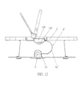
FIG. 17 is a perspective diagram illustrating an exploded view of the partial components of the connection mechanism which are disposed on the carrier device in the fifth embodiment according to the invention, -
FIG. 18 is a perspective diagram illustrating an assembly of the partial components of the connection mechanism which are disposed on the carrier device in the fifth embodiment according to the invention, and -
FIG. 19 is an exploded view of the connection mechanism for detaching the carrier device from a supporting device in the fifth embodiment according to the invention. - A first embodiment according to the invention is described first of all, as shown by
FIG. 1 andFIG. 2 .FIG. 1 andFIG. 2 illustrate aninfant care equipment 200 according to the invention. In the embodiment, for example, theinfant care equipment 200 is an infant stroller but not limited thereto. Theinfant care equipment 200 includes acarrier device 201, a supportingdevice 202, and twoconnection mechanisms 100. Theconnection mechanism 100 is used for detachably installing thecarrier device 201 to the supportingdevice 202. Theconnection mechanisms 100 are disposed symmetrically at two sides of each of thecarrier device 201 and the supportingdevice 202. Thecarrier device 201 can be installed forwards or backwards on the supportingdevice 202. Theconnection mechanism 100 includes afirst base 1, asecond base 2, alatch 3, and anoperating component 400. Thefirst base 1 is fixed on the supportingdevice 202. Thesecond base 2 is fixed on thecarrier device 201 and detachably connected to thefirst base 1. Thelatch 3 is movably disposed on thesecond base 2 and corresponds to thefirst base 1. Theoperating component 400 is disposed on thesecond base 2 and operably connected to thelatch 3. Theoperating component 400 selectively drives thelatch 3 to move to a locking position so that thesecond base 2 is locked to thefirst base 1, or drives thelatch 3 to move to an unlocking position so that thesecond base 2 is unlocked from thefirst base 1. - Please refer to
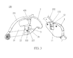
FIG. 3 . Theconnection mechanism 100 of the embodiment includes thefirst base 1, thesecond base 2, thelatch 3, and theoperating component 400. Thefirst base 1 includes afirst base body 11 and a blockingpart 12. Thefirst base body 11 has arecess 111. The blockingpart 12 is formed on an inner side wall of therecess 111. Thesecond base 2 includes asecond base body 21 and aprotrusive block 22. Theprotrusive block 22 is formed on thesecond base body 21 and detachably accommodated in therecess 111. By the cooperation of theprotrusive block 22 with therecess 111, thefirst base 1 and thesecond base 2 can slide relatively only in a vertical direction, which is conducive to locking or unlocking of thefirst base 1 and thesecond base 2 by theoperating component 400. Theprotrusive block 22 has a first slidingslot 221 and a second slidingslot 222. Thelatch 3 is slidably disposed in the first slidingslot 221. By the blockingpart 12 sliding in the second slidingslot 222, thesecond base 2 is installed to thefirst base 1 in an installation direction. Thelatch 3 has a guidingportion 31 corresponding to the blockingpart 12 in the installation direction. The guidingportion 31 shrinks gradually in a direction toward the locking position. Concretely, the bottom surface of the guidingportion 31 is an oblique surface. Thesecond base 2 slides downward during the engagement of thesecond base 2 with thefirst base 1, so the disposition of the guidingportion 31 makes thelatch 3 interact with the blockingpart 12 during the locking of thelatch 3, so that thelatch 3 can automatically retract into the first slidingslot 221 during the downward sliding of thesecond base 2. Thereby, theprotrusive block 22 of thesecond base 2 can be totally engaged in therecess 111 of thefirst base 1 smoothly. The structure is simple; the operating is convenient. - Please refer to
FIGS. 4 through 6 . Theoperating component 400 includes afirst operating part 4, asecond operating part 5, atransmission part 6, and a firstelastic part 7. Thefirst operating part 4 includes afirst operating body 410. Thefirst operating body 410 of thefirst operating part 4 is movably disposed on a first portion of thesecond base 2 and connected to thelatch 3. Thefirst operating body 410 of thefirst operating part 4 selectively drives thelatch 3 to move to the locking position, or drives thelatch 3 to move to the unlocking position. When in the locking position, the guidingportion 31 of thelatch 3 protrudes outside theprotrusive block 22 and abuts against the blockingpart 12. When in the unlocking position, the guidingportion 31 of thelatch 3 retracts in theprotrusive block 22 and disengages from the blockingpart 12. Thefirst operating part 4 has a first slantedslot 41 having a firstinclined surface 411; that is, thefirst operating body 410 of thefirst operating part 4 has the first slantedslot 41 having the firstinclined surface 411. The extension direction of the first slantedslot 41 slants to the movement direction of thefirst operating part 4. Thereby, the firstinclined surface 411 is driven to abut against thelatch 3 so that the movement direction of thefirst operating body 410 of thefirst operating part 4 crosses with the movement direction of thelatch 3. In the embodiment, the movement direction of thefirst operating part 4 is perpendicular to the movement direction of thelatch 3. A longitudinal movement of thefirst operating part 4 can be transferred a transverse movement of thelatch 3 through the firstinclined surface 411, so that thelatch 3 can move in the first slidingslot 221 back and forth. Thelatch 3 includes alatch body 32 and apin body 33. The guidingportion 31 is formed at an outside end of thelatch body 32. Thepin body 33 is fixedly connected to thelatch body 32, movably accommodated in the first slantedslot 41, and driven to abut against the firstinclined surface 411. Thepin body 33 performs the effect of connecting thelatch body 32 with thefirst operating body 410 of thefirst operating part 4 and sliding in the first slantedslot 41, so that thepin body 33 cooperates with the first slantedslot 41 to limit the movement direction of thelatch body 32. The firstelastic part 7 elastically abuts against between thesecond base 2 and thefirst operating body 410 of thefirst operating part 4 so that thefirst operating part 4 has a tendency to drive thelatch 3 to move to the locking position. The firstelastic part 7 is a compression spring. Thelatch 3 can automatically move back to its original position by a resilient force provided by the firstelastic part 7, so that the steps of the operating can be reduced and the installation and detachment of the connection mechanism is more convenient and quick. Thesecond operating part 5 is movably disposed on a second portion of thesecond base 2. The second portion is far away from the first portion. Thetransmission part 6 is connected between thefirst operating body 410 of thefirst operating part 4 and thesecond operating part 5. Thetransmission part 6 is a steel wire in a tight state so as to transmit an external force applied to thesecond operating part 5 by a user; however, the invention is not limited thereto. Therein, thesecond operating part 5 moves and drives thefirst operating part 4 through thetransmission part 6. Although the second portion is far away from the first portion, the user still can remotely manipulate thesecond operating part 5 to control the movement of thelatch 3. - Please refer to
FIGS. 3 through 6 together. When thelatch 3 of theconnection mechanism 100 of the embodiment is in the locking position, theprotrusive block 22 is accommodated in therecess 111. The bottom surface of theprotrusive block 22 abuts against the inner bottom wall of therecess 111. The firstelastic part 7 abuts against thefirst operating part 4 so that thelatch 3 reaches out and keeps located at the locking position where thelatch 3 abuts against the blockingpart 12. Accordingly, thesecond base 2 is locked to thefirst base 1, and thecarrier device 202 is installed to the supportingdevice 201. If it is required to detach thecarrier device 202 from the supportingdevice 201, thesecond operating part 5 can be driven by hand pressing or by electric power so that thesecond operating part 5 drives thefirst operating part 4 through thetransmission part 6, and thefirst operating part 4 moves horizontally. When moving horizontally, thefirst operating part 4 moves thelatch 3 through the firstinclined surface 411 so that thelatch 3 retracts back and moves to the unlocking position. During the moving of thelatch 3 to the unlocking position, thelatch 3 also compresses the firstelastic part 7. At the moment, thelatch 3 is disengaged from the blockingpart 12 so that thesecond base 2 is unlocked from thefirst base 1. If re-locking is required, thesecond operating part 5 is to be released so that the firstelastic part 7 is restored to release elastic potential energy. Accordingly, the firstelastic part 7 drives thelatch 3 through thefirst operating part 4 so that thelatch 3 abuts against the blockingpart 12 leading to thesecond base 2 being locked to thefirst base 1. - In the first embodiment of the present invention, the
first base 1 is detachably connected to thesecond base 2. Thelatch 3 can be driven to move to the locking position or the unlocking position by theoperating component 400. Therein, the movement direction of thelatch 3 is perpendicular to the sliding direction of thesecond base 2 relative to thefirst base 1. Thereby, when thelatch 3 is located at the locking position, the purpose of locking thesecond base 2 with thefirst base 1 can be achieved; when thelatch 3 is located at the unlocking position, the purpose of unlocking thesecond base 2 from thefirst base 1 can be achieved. Theconnection mechanism 100 is very firm, safe and reliable in use. Thesecond base 2 can be installed to or detached from thefirst base 1 by operating theoperating component 400. Therefore, the control is simple; the installation and detachment is very convenient. - The invention is not limited to the above embodiment and can also be applied to other embodiment. The following will describe a second embodiment according to the invention. As shown by
FIGS. 7 through 9 , the structure of the second embodiment is substantially similar to the first embodiment; similar component notations indicate similar components. One of differences between the two embodiments is the transmission part and the transmission mechanism thereof. A transmission part 6' of the second embodiment is but not limited to a plate or rod with a fixed shape. The transmission part 6' is fixedly connected to thefirst operating part 4 and thesecond operating part 5. The firstelastic part 7 is disposed at a side of the transmission part 6' . One end of the firstelastic part 7 abuts against thefirst operating part 4; the other end of the firstelastic part 7 abuts against thesecond base 2. When thelatch 3 is located at the locking position, the firstelastic part 7 abuts against the transmission part 6' so that thefirst operating part 4 keeps thelatch 3 located at the locking position. When unlocking is required, thesecond operating part 5 can be manipulated to move upward so that the transmission part 6' moves vertically to drive thefirst operating part 4 to move upward. Thefirst operating part 4 drives thelatch 3 to move toward the unlocking position and to compress the firstelastic part 7. As in the unlocking position, thelatch 3 is disengaged from the blockingpart 12. When locking is required, thelatch 3 has to be moved to the locking position again, thesecond operating part 5 can be released so that the firstelastic part 7 releases elastic potential energy to make thelatch 3 abut against the blockingpart 12 leading to thesecond base 2 being locked on thefirst base 1. - The invention is not limited to the above embodiment and can also be applied to other embodiments. The following will describe a third embodiment according to the invention. Please refer to
FIG. 10 andFIG. 11 . The third embodiment is substantially similar in structure to the above embodiments; similar component notations indicate similar components. One of differences between the third embodiment and the above embodiments is the connection structure and the linkage mechanism of the operating component with the latch. Aconnection mechanism 100 of this embodiment includes afirst base 1, asecond base 2, a latch 3', and an operating component 400'. Thefirst base 1 includes afirst base body 11 and a blockingpart 12. The first base body has arecess 111. The blockingpart 12 is formed on an inner side wall of therecess 111. Thesecond base 2 includes asecond base body 21 and aprotrusive block 22. Theprotrusive block 22 is formed on thesecond base body 21 and detachably accommodated in therecess 111. Theprotrusive block 22 has a first slidingslot 221 and a second slidingslot 222. The latch 3' is slidably disposed in the first slidingslot 221. The latch 3' includes a latch body 32'. A guidingportion 31 is formed at an outside end of the latch body 32'. - Please refer to
FIG. 11 . The operating component 400' includes a first operating part 4', a second operating part 5', a transmission part 6', and a first elastic part 7'. In this embodiment, the first portion is a little far away from the second portion. The first operating part 4' includes a first operating body 410'. An end of a first operating body 410' is fixedly connected to an inside end of the latch body 32' of the latch 3' , or the first operating body 410' and the latch 3' are formed integrally in one piece. The first operating body 410' has a first long slot 41' and an accommodating recess 42' accommodating the first elastic part 7' . Thesecond base 2 further includes arod body 23. Therod body 23 is inserted in the first long slot 41' so that the first operating part 4' can move on thesecond base 2. One end of the transmission part 6' is fixedly connected to another end of the first operating part 4', or the transmission part 6' and the first operating part 4' are formed integrally in one piece. The second operating part 5' is fixedly connected to the other end of the transmission part 6', or the second operating part 5' and the transmission part 6' are formed integrally in one piece. Substantially, the first operating part 4', the second operating part 5', the transmission part 6' , and the latch 3' are formed integrally in one piece; however, the invention is not limited thereto. The movement direction of the first operating part 4', the second operating part 5', the transmission part 6', and the latch 3' is parallel to the extension direction of the first long slot 41'. The first elastic part 7' is disposed in the accommodating recess 42' and elastically abuts against and between therod body 23 of thesecond base 2 and the first operating body 410' of the first operating part 4', so that the first operating part 4' has a tendency to drive the latch 3' to move to the locking position. The first elastic part 7' is a compression spring. - Please refer to
FIG. 10 andFIG. 11 together. If it is required to unlock thefirst base 1 and thesecond base 2, the second operating part 5' can be driven by hand drawing or by electric power so that the second operating part 5' moves the first operating part 4' through the transmission part 6' . The first operating part 4' moves and drives the latch 3' to move. The latch 3' retracts in the first slidingslot 221 and drives the first operating part 4' to compress the first elastic part 7'. At the moment, the latch 3' is disengaged from the blockingpart 12 so that thesecond base 2 is unlocked from thefirst base 1. When re-locking is required, the second operating part 5' is to be released so that the first elastic part 7' is restored under the resilient force to move the first operating part 4' to drive the latch 3' to protrude out the first slidingslot 221 and abut against the blockingpart 12. Accordingly, thesecond base 2 and thefirst base 1 are locked with each other. - The invention is not limited to the above embodiment and can also be applied to other embodiments. The following will describe a fourth embodiment according to the invention. The fourth embodiment is substantially similar in structure to the above embodiments; similar component notations indicate similar components. One of differences between the fourth embodiment and the above embodiments is the structure of the operating component and the linkage mechanism thereof. As shown by
FIGS. 12 through 15 , aconnection mechanism 100 of this embodiment includes afirst base 1, asecond base 2, alatch 3, and anoperating component 400. In the embodiment, for example, thesecond base 2 is but not limited to a crib box. Theoperating component 400 includes afirst operating part 4, a second operating part 5', a transmission part 6', and a firstelastic part 7. - As shown by
FIG. 15 , the second operating part 5' includes a pivot connection portion 51' and a driving portion 52'. The pivot connection portion 51' is pivotally connected to thesecond base 2. The driving portion 52' is connected to the pivot connection portion 51' and has a second inclined surface 521'. The transmission part 6' includes a driven portion 61' and a transmission portion 62'. The driven portion 61' is slidably disposed on thesecond base 2 and driven to abut against the second inclined surface 521'. The sliding direction of the driven portion 61' crosses with the extension direction of the second inclined surface 521'. Specifically, the sliding direction of the driven portion 61' slants to the extension direction of the second inclined surface 521'. The transmission portion 62' is connected between thefirst operating body 410 of thefirst operating part 4 and the driven portion 61'. The transmission portion 62' is a steel wire. The pivot connection portion 51' pivots to drive the driving portion 52' so that the second inclined surface 521' abuts against the driven portion 61' to drive first operatingpart 4 through the transmission portion 62'. - Please refer to
FIGS. 12 through 15 together. When it is required to unlock thefirst base 1 and thesecond base 2, the driving portion 52' can be driven by pressing so that the driving portion 52' rotates due to the pivotal connection of the pivot connection portion 51' The second inclined surface 521' moves upward to push the driven portion 61' to move horizontally left on thesecond base 2. The driven portion 61' drives thefirst operating part 4 through the transmission portion 62' so that thefirst operating part 4 moves on thefirst base 1. The firstinclined surface 411 of the first slantedslot 41 of thefirst operating part 4 drives thepin body 33 of thelatch 3 to move, so that thelatch body 32 of thelatch 3 is disengaged from the blockingpart 12 and compresses the firstelastic part 7. At the moment, thesecond base 2 is unlocked from thefirst base 1. When re-locking is required, the driving portion 52' is to be released so that the driven portion 61' is no longer confined by the second inclined surface 521' and capable of sliding horizontally right on thesecond base 2. At the moment, under the resilient force by the firstelastic part 7, the firstinclined surface 411 of the first slantedslot 41 abuts against thepin body 33 of thelatch 3, so that thelatch 3 moves and thelatch body 32 of thelatch 3 abuts against blockingpart 12 leading to thesecond base 2 being locked to thefirst base 1. - The invention is not limited to the above embodiment and can also be applied to other embodiments. The following will describe a fifth embodiment according to the invention. The fifth embodiment is substantially similar in structure to the above embodiments; similar component notations indicate similar components. One of differences between the fifth embodiment and the above embodiments is the structure and the linkage mechanism of the operating component and the latch. Please refer to
FIGS. 16 through 19 . Aconnection mechanism 100 of this embodiment includes afirst base 1, asecond base 2, alatch 3, and anoperating component 400". Theoperating component 400" includes afirst operating part 4", asecond operating part 5", atransmission part 6", a secondelastic part 8, and a thirdelastic part 9. Thefirst operating part 4" is movably disposed on a first portion of thesecond base 2 and connected to thelatch 3. Thefirst operating part 4" includes afirst operating body 410". Thefirst operating body 410" has a first slantedslot 41". The firstslanted slot 41" has a firstinclined surface 411". In the embodiment, the first slantedslot 41" is structurally designed in an open type, but it can be designed in a semi-open type or a close type as the above embodiments. The movement direction of the firstinclined surface 411" of the first slantedslot 41" of thefirst operating body 410" crosses with the movement direction of thelatch 3. Thesecond operating part 5" is movably disposed on a second portion of thesecond base 2. Thetransmission part 6" is connected between thefirst operating part 4" and thesecond operating part 5". Therein, thesecond operating part 5" moves and drives thefirst operating part 4" through thetransmission part 6". The secondelastic part 8 elastically abuts against and between thesecond base 2 and thelatch body 32 of thelatch 3 so that thelatch body 32 of thelatch 3 has a tendency to move to the locking position. Concretely, thelatch body 32 of thelatch 3 has ahole 34. The secondelastic part 8 is accommodated in thehole 34. One end of the secondelastic part 8 abuts against thelatch body 32 of thelatch 3; the other end of the secondelastic part 8 abuts against thesecond base 2. Thepin body 33 of thelatch 3 cooperates with the firstinclined surface 411" so that thefirst operating part 4" drives thelatch 3 to move in the first slidingslot 221. In the embodiment, because the first slantedslot 41" is structurally designed in an open type, thewhole pin body 33 can be accommodated in the first slantedslot 41". If the first slantedslot 41" is designed in a semi-open type or a close type as the above embodiments, thepin body 33 is partially inserted into the first slantedslot 41". - Please refer to
FIG. 16 again. Thesecond operating part 5" includes apivot connection portion 51" and a drivingportion 52". Thepivot connection portion 51" is pivotally connected to thesecond base 2. The drivingportion 52" is connected to thepivot connection portion 51" and has a secondinclined surface 521". Concretely, the drivingportion 52" has a secondslanted slot 522" having the secondinclined surface 521". Thetransmission part 6" includes a drivenportion 61" and atransmission portion 62". The drivenportion 61" is slidably disposed on thesecond base 2, inserted in the secondslanted slot 522", and driven to abut against the secondinclined surface 521". In the embodiment, the drivenportion 61" is a rod part. Thetransmission portion 62" is connected between thefirst operating body 410" of thefirst operating part 4" and the drivenportion 61". In the embodiment, thetransmission portion 62" is a steel wire. The sliding direction of the drivenportion 62" crosses with the extension direction of the secondinclined surface 521". Concretely, the sliding direction of the drivenportion 61" slants to the extension direction of the secondinclined surface 521". The thirdelastic part 9 elastically abuts against between thesecond base 2 and the drivingportion 52" of thesecond operating part 5" so that thesecond operating part 5" has a has a tendency to move back to an initial status driving thefirst operating part 4". Concretely, one end of the thirdelastic part 9 abuts against thesecond base 2; the other end of the thirdelastic part 9 abuts against the drivingportion 52". - Please refer to
FIGS. 16 through 19 together. If it is required to unlock thesecond base 2 and thefirst base 1, the drivingportion 52" can be driven by pressing so that the drivingportion 52" rotates due to the pivotal connection of thepivot connection portion 51". The secondinclined surface 521" moves upward to push the drivenportion 61" to horizontally move right in the secondslanted slot 522". At the moment, the drivenportion 61" moves right in the horizontal direction. During the movement of the drivenportion 61", the drivenportion 61" drives thefirst operating body 410" of thefirst operating part 4" through thetransmission portion 62" so that thefirst operating body 410" moves on thefirst base 1. The firstinclined surface 411" of the first slantedslot 41" of thefirst operating body 410" of thefirst operating part 4" drives thepin body 33 of thelatch 3 to move so that thelatch body 32 of thelatch 3 is disengaged from the blockingpart 12 and compresses the secondelastic part 8. At the moment, thesecond base 2 is unlocked from thefirst base 1. When re-locking is required, the drivingportion 52" is to be released so that thelatch body 32 of thelatch 3 abuts against the blockingpart 12 under the resilient force by the secondelastic part 8 leading to thesecond base 2 being locked to thefirst base 1.
Claims (20)
- A connection mechanism (100) for detachably installing a carrier device (201) to a supporting device (202), characterized by comprisinge:a first base (1) fixed on the supporting device (202);a second base (2) fixed on the carrier device (201) and detachably connected to the first base (1);a latch (3) movably disposed on the second base (2), the latch (3) corresponding to the first base (1); andan operating component (400) disposed on the second base (2) and operably connected to the latch (3), the operating component (400) selectively driving the latch (3) to move to a locking position so that the second base (2) is locked to the first base (1), or driving the latch (3) to move to an unlocking position so that the second base (2) is unlocked from the first base (1).
- The connection mechanism (100) of claim 1, characterized in that the first base (1) comprises a first base body (11) and a blocking part (12), the first base body (11) has a recess (111), the blocking part (12) is formed on an inner side wall of the recess (111), the second base (2) comprises a second base body (21) and a protrusive block (22), the protrusive block (22) is formed on the second base body (21) and detachably accommodated in the recess (111), and when the protrusive block (22) is accommodated in the recess (111), a bottom surface of the protrusive block (22) abuts against an inner bottom wall of the recess (111), and the operating component (400) drives the latch (3) to move to the locking position so that the latch (3) abuts against the blocking part (12) leading to the second base (2) being locked to the first base (1).
- The connection mechanism (100) of claim 2, characterized in that the second base (2) is installed to the first base (1) in an installation direction, and the latch (3) has a guiding portion (31) corresponding to the blocking part (12) in the installation direction.
- The connection mechanism (100) of claim 3, characterized in that the guiding portion (31) shrinks gradually in a direction toward the locking position.
- The connection mechanism (100) of claim 1, characterized in that the operating component (400) comprises a first operating part (4) movably disposed on a first portion of the second base (2) and connected to the latch (3), and the first operating part (4) selectively drives the latch (3) to move to the locking position or drives the latch (3) to move to the unlocking position.
- The connection mechanism (100) of claim 5, characterized in that a movement direction of the first operating part (4) crosses with a movement direction of the latch (3).
- The connection mechanism (100) of claim 6, characterized in that the movement direction of the first operating part (4) is perpendicular to the movement direction of the latch(3).
- The connection mechanism (100) of claim 6, characterized in that the first operating part (4) has a first inclined surface (411) driven to abut against the latch (3) so that the movement direction of the first operating part (4) crosses with the movement direction of the latch (3).
- The connection mechanism (100) of claim 8, characterized in that the first operating part (4) comprises a first operating body (410) having a first slanted slot (41) thereon forming the first inclined surface (411), the latch (3) comprises a latch body (32) and a pin body (33), and the pin body (33) is connected to the latch body (32), movably accommodated in the first slanted slot (41), and driven to abut against the first inclined surface (411).
- The connection mechanism (100) of claim 5, characterized in that a movement direction of the first operating part (4) is parallel to a movement direction of the latch (3).
- The connection mechanism (100) of claim 10, characterized in that the first operating part (4') comprises a first operating body (410') having a first long slot (41'), the second base (2) comprises a rod body (23) accommodated in the first long slot (41') so that the first operating part (4') is capable of moving on the second base (2), and the movement direction of the first operating part (4') and the movement direction of the latch (3') are parallel to an extension direction of the first long slot (41').
- The connection mechanism (100) of claim 5, characterized in that the operating component (400) comprises a first elastic part (7) elastically abutting against between the second base (2) and the first operating part (4) so that the first operating part (4) has a tendency to drive the latch (3) to move to the locking position.
- The connection mechanism (100) of claim 5, characterized in that the operating component (400") comprises a second elastic part (8) elastically abutting against between the second base (2) and the latch (3) so that the latch (3) has a tendency to move to the locking position.
- The connection mechanism (100) of claim 5, characterized in that the operating component (400) comprises a second operating part (5) and a transmission part (6), the second operating part (5) is movably disposed on a second portion of the second base (2), the second portion is far away from the first portion, the transmission part (6) is connected between the first operating part (4) and the second operating part (5), and the second operating part (5) moves to drive the first operating part (4) through the transmission part (6).
- The connection mechanism (100) of claim 14, characterized in that the second operating part (5') comprises a pivot connection portion (51') and a driving portion (52'), the pivot connection portion (51') is pivotally connected to the second base (2), the driving portion (52') is connected to the pivot connection (51') portion and has a second inclined surface (521'), the transmission part (6') comprises a driven portion (61') and a transmission portion (62'), the driven portion (61') is slidably disposed on the second base (2) and driven to abut against the second inclined surface (521'), the transmission portion (62') is connected between the first operating part (4) and the driven portion (61'), and the pivot connection portion (51') pivots to drive the driving portion (52') to pivot so that the second inclined surface (521') abuts against the driven portion (61') to drive the first operating part (4) through the transmission portion (62').
- The connection mechanism (100) of claim 15, characterized in that a sliding direction of the driven portion (61') crosses with an extension direction of the second inclined surface (521').
- The connection mechanism (100) of claim 16, characterized in that the sliding direction of the driven portion (61') slants to the extension direction of the second inclined surface (521').
- The connection mechanism (100) of claim 15, characterized in that the driving portion (52") has a second slanted slot (522") thereon forming the second inclined surface (521"), and the driven portion (61") is a rod part which is movably accommodated in the second slanted slot (522") and driven to abut against the second inclined surface (521").
- The connection mechanism (100) of claim 14, characterized in that the operating component (400") comprises a third elastic part (9) elastically abutting against between the second base (2) and the second operating part (5") so that the second operating part (5") has a tendency to move back to an initial status driving the first operating part (4").
- An infant care equipment (200) comprising a carrier device (201) and a supporting device (202), the infant care equipment (200) characterized by further comprising any connection mechanism (100) of claims 1 to 19, the connection mechanism (100) being used for detachably installing the carrier device (201) to the supporting device (202).
Priority Applications (1)
| Application Number | Priority Date | Filing Date | Title |
|---|---|---|---|
| EP18180324.8A EP3403900B1 (en) | 2013-06-13 | 2014-06-11 | Connection mechanism and infant care equipment having the connection mechanism |
Applications Claiming Priority (1)
| Application Number | Priority Date | Filing Date | Title |
|---|---|---|---|
| CN201310233667.1A CN104228921B (en) | 2013-06-13 | 2013-06-13 | Connecting device and infant care equipment with same |
Related Child Applications (2)
| Application Number | Title | Priority Date | Filing Date |
|---|---|---|---|
| EP18180324.8A Division EP3403900B1 (en) | 2013-06-13 | 2014-06-11 | Connection mechanism and infant care equipment having the connection mechanism |
| EP18180324.8A Division-Into EP3403900B1 (en) | 2013-06-13 | 2014-06-11 | Connection mechanism and infant care equipment having the connection mechanism |
Publications (2)
| Publication Number | Publication Date |
|---|---|
| EP2813412A1 true EP2813412A1 (en) | 2014-12-17 |
| EP2813412B1 EP2813412B1 (en) | 2018-10-24 |
Family
ID=50927971
Family Applications (2)
| Application Number | Title | Priority Date | Filing Date |
|---|---|---|---|
| EP14171886.6A Active EP2813412B1 (en) | 2013-06-13 | 2014-06-11 | Connection mechanism and infant care equipment having the connection mechanism |
| EP18180324.8A Active EP3403900B1 (en) | 2013-06-13 | 2014-06-11 | Connection mechanism and infant care equipment having the connection mechanism |
Family Applications After (1)
| Application Number | Title | Priority Date | Filing Date |
|---|---|---|---|
| EP18180324.8A Active EP3403900B1 (en) | 2013-06-13 | 2014-06-11 | Connection mechanism and infant care equipment having the connection mechanism |
Country Status (4)
| Country | Link |
|---|---|
| US (1) | US9840168B2 (en) |
| EP (2) | EP2813412B1 (en) |
| CN (2) | CN104228921B (en) |
| TW (1) | TWI569999B (en) |
Families Citing this family (29)
| Publication number | Priority date | Publication date | Assignee | Title |
|---|---|---|---|---|
| US9944305B2 (en) * | 2008-12-04 | 2018-04-17 | Baby Jogger, LLC | Removable seat attachment for a stroller |
| US11577771B2 (en) * | 2008-12-04 | 2023-02-14 | Baby Jogger, LLC | Removable seat attachment for a stroller |
| GB201420312D0 (en) * | 2014-11-14 | 2014-12-31 | Silver Cross Holdings Ltd | Carrier Mounting |
| CN205478737U (en) * | 2016-03-22 | 2016-08-17 | 明门香港股份有限公司 | Connecting structure and infant bearing device with same |
| US10960913B2 (en) | 2016-07-27 | 2021-03-30 | Kolcraft Enterprises, Inc. | Foldable strollers and related methods |
| CN109715473B (en) | 2016-07-27 | 2022-03-04 | 考可拉夫特公司 | Stroller with removable seat and related method |
| US10994763B2 (en) * | 2016-07-27 | 2021-05-04 | Kolcraft Enterprises, Inc. | Foldable strollers with removeable seats and related methods |
| CN108454688B (en) * | 2017-02-21 | 2023-09-12 | 珠海阳光儿童用品有限公司 | Locking mechanism and stroller |
| CN106965841A (en) * | 2017-03-19 | 2017-07-21 | 张新 | The multi-functional equipment of double suspensions and device for transporting children |
| CN106891927A (en) * | 2017-03-19 | 2017-06-27 | 张新 | For the multi-functional equipment and device of transporting children |
| CN106904203A (en) * | 2017-03-19 | 2017-06-30 | 张新 | For double suspensions of transporting children equipment capable of reversing and device |
| CN106891963A (en) * | 2017-03-19 | 2017-06-27 | 张新 | For the equipment and device of double suspensions of transporting children |
| CN106904200A (en) * | 2017-03-19 | 2017-06-30 | 张新 | For the multi-functional equipment of double suspensions and device of transporting children |
| CN106891932A (en) * | 2017-03-19 | 2017-06-27 | 张新 | For the multi-functional equipment of double suspensions and device of transporting children |
| CN106891931A (en) * | 2017-03-19 | 2017-06-27 | 张新 | For the multi-functional equipment of many suspensions and device of transporting children |
| CN106891928A (en) * | 2017-03-19 | 2017-06-27 | 张新 | For the multi-functional equipment and device of transporting children |
| CN106882224A (en) * | 2017-03-19 | 2017-06-23 | 张新 | For the multi-functional equipment of double suspensions and device of transporting children |
| CN109689472B (en) | 2017-07-27 | 2021-10-08 | 考可拉夫特公司 | frame for stroller |
| WO2020232651A1 (en) * | 2019-05-22 | 2020-11-26 | 深圳市喜德盛自行车股份有限公司 | Baby carriage seat packet |
| CN116424415A (en) * | 2019-12-13 | 2023-07-14 | 明门瑞士股份有限公司 | stroller |
| CN113302788A (en) * | 2020-07-07 | 2021-08-24 | 深圳市大疆创新科技有限公司 | Housing structure, battery, electronic device and movable platform |
| CN119058800A (en) * | 2020-10-09 | 2024-12-03 | 明门(中国)幼童用品有限公司 | Mounting components, mounting assemblies and carriers |
| CN118744668A (en) | 2020-10-20 | 2024-10-08 | 宝钜瑞士股份有限公司 | Car seat base structure |
| CN114532798A (en) | 2020-11-26 | 2022-05-27 | 明门瑞士股份有限公司 | Clamping structure |
| CN114715252A (en) * | 2021-01-04 | 2022-07-08 | 明门瑞士股份有限公司 | Frame locking mechanism and handcart with same |
| CN114802407A (en) * | 2021-01-28 | 2022-07-29 | 明门瑞士股份有限公司 | Fixing device, and passenger device and carrier device using the same |
| CN118596959A (en) * | 2021-01-29 | 2024-09-06 | 宝钜瑞士股份有限公司 | Baby Carrier |
| CN115520263A (en) | 2021-06-25 | 2022-12-27 | 明门(中国)幼童用品有限公司 | Baby carriage and basket clamping mechanism |
| CN114852157B (en) * | 2022-04-21 | 2024-05-03 | 福建欧仕儿童用品股份有限公司 | Cart convertible into automobile safety seat base |
Citations (9)
| Publication number | Priority date | Publication date | Assignee | Title |
|---|---|---|---|---|
| DE20016909U1 (en) * | 2000-09-30 | 2001-01-25 | Fa. Joh. Georg Hartan, 96242 Sonnefeld | Baby or doll stroller |
| EP1818239A1 (en) * | 2006-02-14 | 2007-08-15 | Jane, S.A. | A device for fitting seats and the like to the chassis of prams |
| US20080303232A1 (en) * | 2007-06-06 | 2008-12-11 | Shun-Min Chen | Stroller and seat assembly mechanism for a stroller |
| EP2108566A1 (en) * | 2008-04-09 | 2009-10-14 | Maxi Miliaan B.V. | Assembly comprising a chassis and a child seat being detachably connectable to the chassis, such a chassis as well as such a child seat |
| WO2010040644A1 (en) * | 2008-10-10 | 2010-04-15 | Scs (London) Limited | Apparatus and method |
| US20100244408A1 (en) * | 2009-03-24 | 2010-09-30 | Graco Children's Products Inc. | Foldable Stroller and Fold Interlock Mechanism |
| US20110278810A1 (en) * | 2010-05-13 | 2011-11-17 | Nuna International B.V. | Latch device for coupling a carrier to a stroller frame |
| CN202294915U (en) * | 2011-10-11 | 2012-07-04 | 明门香港股份有限公司 | Children's barrow |
| US20120267925A1 (en) * | 2004-05-17 | 2012-10-25 | Orbit Baby, Inc. | Modular child restraint system |
Family Cites Families (12)
| Publication number | Priority date | Publication date | Assignee | Title |
|---|---|---|---|---|
| US5718439A (en) * | 1996-05-31 | 1998-02-17 | Wang; Frank | Stroller with detachable seat member |
| US5820144A (en) * | 1996-05-31 | 1998-10-13 | Wang; Frank | Stroller with shock absorbing device for mounting a seat member on a stroller frame |
| US5947555A (en) * | 1996-11-22 | 1999-09-07 | Kolcraft Enterprises, Inc. | Infant seat and stroller coupling system |
| DE19914528A1 (en) * | 1999-03-30 | 2000-10-12 | Link Treasure Ltd | Connecting device for push-chair (stroller) seat, with two bars on either side of frame for locking seat unit, normally locked but movable to release position |
| CN100395135C (en) * | 2002-09-12 | 2008-06-18 | 株式会社东仁技研 | Multipurpose Child Vehicle Seat |
| CN2712756Y (en) * | 2004-07-02 | 2005-07-27 | 好孩子儿童用品有限公司 | Children's vehicle with fixing device for automobile seat |
| CN101367343A (en) * | 2007-08-13 | 2009-02-18 | 好孩子儿童用品有限公司 | Combination of car seat and stroller |
| CN101934810B (en) * | 2009-06-30 | 2013-01-23 | 明门实业股份有限公司 | Baby carriage and bracket adjusting device |
| CN102530047B (en) * | 2010-12-20 | 2013-11-27 | 明门香港股份有限公司 | baby carrier |
| CN102616266A (en) * | 2011-02-01 | 2012-08-01 | 明门香港股份有限公司 | Baby bearing device and baby carriage |
| CN102991560B (en) * | 2011-09-08 | 2016-01-13 | 明门香港股份有限公司 | Baby carriage frame and shank rest device thereof |
| CN202345738U (en) * | 2011-09-22 | 2012-07-25 | 明门香港股份有限公司 | Children's barrow |
-
2013
- 2013-06-13 CN CN201310233667.1A patent/CN104228921B/en active Active
- 2013-06-13 CN CN201610339787.3A patent/CN105966447B/en active Active
-
2014
- 2014-06-09 US US14/298,978 patent/US9840168B2/en active Active
- 2014-06-09 TW TW103119929A patent/TWI569999B/en active
- 2014-06-11 EP EP14171886.6A patent/EP2813412B1/en active Active
- 2014-06-11 EP EP18180324.8A patent/EP3403900B1/en active Active
Patent Citations (9)
| Publication number | Priority date | Publication date | Assignee | Title |
|---|---|---|---|---|
| DE20016909U1 (en) * | 2000-09-30 | 2001-01-25 | Fa. Joh. Georg Hartan, 96242 Sonnefeld | Baby or doll stroller |
| US20120267925A1 (en) * | 2004-05-17 | 2012-10-25 | Orbit Baby, Inc. | Modular child restraint system |
| EP1818239A1 (en) * | 2006-02-14 | 2007-08-15 | Jane, S.A. | A device for fitting seats and the like to the chassis of prams |
| US20080303232A1 (en) * | 2007-06-06 | 2008-12-11 | Shun-Min Chen | Stroller and seat assembly mechanism for a stroller |
| EP2108566A1 (en) * | 2008-04-09 | 2009-10-14 | Maxi Miliaan B.V. | Assembly comprising a chassis and a child seat being detachably connectable to the chassis, such a chassis as well as such a child seat |
| WO2010040644A1 (en) * | 2008-10-10 | 2010-04-15 | Scs (London) Limited | Apparatus and method |
| US20100244408A1 (en) * | 2009-03-24 | 2010-09-30 | Graco Children's Products Inc. | Foldable Stroller and Fold Interlock Mechanism |
| US20110278810A1 (en) * | 2010-05-13 | 2011-11-17 | Nuna International B.V. | Latch device for coupling a carrier to a stroller frame |
| CN202294915U (en) * | 2011-10-11 | 2012-07-04 | 明门香港股份有限公司 | Children's barrow |
Also Published As
| Publication number | Publication date |
|---|---|
| US9840168B2 (en) | 2017-12-12 |
| CN105966447B (en) | 2018-02-09 |
| TWI569999B (en) | 2017-02-11 |
| EP3403900A1 (en) | 2018-11-21 |
| CN104228921B (en) | 2016-09-14 |
| TW201446574A (en) | 2014-12-16 |
| CN104228921A (en) | 2014-12-24 |
| EP2813412B1 (en) | 2018-10-24 |
| CN105966447A (en) | 2016-09-28 |
| EP3403900B1 (en) | 2020-01-08 |
| US20140369744A1 (en) | 2014-12-18 |
Similar Documents
| Publication | Publication Date | Title |
|---|---|---|
| EP2813412B1 (en) | Connection mechanism and infant care equipment having the connection mechanism | |
| US8287044B2 (en) | Highchair | |
| US11993301B2 (en) | Unlocking device with pause function | |
| US8256833B2 (en) | Child chair having engaging assembly for seat | |
| CN104223845B (en) | Child seat that can be converted into various states of use | |
| US11039694B2 (en) | Child tray assembly and multi-function high chair | |
| CN201665233U (en) | Buckling mechanism of baby safety seat | |
| EP2937262A2 (en) | Baby stroller seat | |
| FR2982469A1 (en) | CHANGING SET AND BABY PARK EQUIPPED WITH A CHANGING TABLE | |
| US11912172B2 (en) | Infant carrier releasing structure, infant carrier and infant safety seat | |
| EP3708462B1 (en) | A carriage frame folding device that can be unlocked along with the folding of the seat | |
| TWI815267B (en) | Child stroller apparatus | |
| US9326618B2 (en) | Lower leg rest adjusting device and infant carrier therewith | |
| CN114379431A (en) | Base structure of automobile safety seat | |
| US20250380824A1 (en) | Fixing device and passenger device as well as carrying device using the same | |
| CN201646448U (en) | child car seat | |
| CN211196326U (en) | Stroller Frames and Strollers | |
| CN112519867A (en) | Unlocking device with pause function | |
| WO2018113320A1 (en) | Chair capable of being used as bed | |
| CN215971222U (en) | Children car safety seat pocket and children car safety seat | |
| CN209852398U (en) | Baby carriage | |
| CN220996495U (en) | Baby carrier with detachable seat | |
| CN220562796U (en) | A kind of dinner plate and children's stroller | |
| TWI919291B (en) | Seat-bed dual-purpose support switching mechanism for bearing device, and bearing device | |
| CN201849518U (en) | Seat device and baby stroller with same |
Legal Events
| Date | Code | Title | Description |
|---|---|---|---|
| 17P | Request for examination filed |
Effective date: 20140611 |
|
| AK | Designated contracting states |
Kind code of ref document: A1 Designated state(s): AL AT BE BG CH CY CZ DE DK EE ES FI FR GB GR HR HU IE IS IT LI LT LU LV MC MK MT NL NO PL PT RO RS SE SI SK SM TR |
|
| AX | Request for extension of the european patent |
Extension state: BA ME |
|
| PUAI | Public reference made under article 153(3) epc to a published international application that has entered the european phase |
Free format text: ORIGINAL CODE: 0009012 |
|
| R17P | Request for examination filed (corrected) |
Effective date: 20150527 |
|
| RBV | Designated contracting states (corrected) |
Designated state(s): AL AT BE BG CH CY CZ DE DK EE ES FI FR GB GR HR HU IE IS IT LI LT LU LV MC MK MT NL NO PL PT RO RS SE SI SK SM TR |
|
| STAA | Information on the status of an ep patent application or granted ep patent |
Free format text: STATUS: EXAMINATION IS IN PROGRESS |
|
| 17Q | First examination report despatched |
Effective date: 20171129 |
|
| RAP1 | Party data changed (applicant data changed or rights of an application transferred) |
Owner name: WONDERLAND SWITZERLAND AG |
|
| GRAP | Despatch of communication of intention to grant a patent |
Free format text: ORIGINAL CODE: EPIDOSNIGR1 |
|
| STAA | Information on the status of an ep patent application or granted ep patent |
Free format text: STATUS: GRANT OF PATENT IS INTENDED |
|
| INTG | Intention to grant announced |
Effective date: 20180726 |
|
| RIN1 | Information on inventor provided before grant (corrected) |
Inventor name: YI, ZE-HUA Inventor name: ZHU, WANQUAN Inventor name: ZHONG, ZHI-REN |
|
| GRAS | Grant fee paid |
Free format text: ORIGINAL CODE: EPIDOSNIGR3 |
|
| GRAA | (expected) grant |
Free format text: ORIGINAL CODE: 0009210 |
|
| STAA | Information on the status of an ep patent application or granted ep patent |
Free format text: STATUS: THE PATENT HAS BEEN GRANTED |
|
| AK | Designated contracting states |
Kind code of ref document: B1 Designated state(s): AL AT BE BG CH CY CZ DE DK EE ES FI FR GB GR HR HU IE IS IT LI LT LU LV MC MK MT NL NO PL PT RO RS SE SI SK SM TR |
|
| REG | Reference to a national code |
Ref country code: CH Ref legal event code: EP |
|
| REG | Reference to a national code |
Ref country code: IE Ref legal event code: FG4D |
|
| REG | Reference to a national code |
Ref country code: CH Ref legal event code: NV Representative=s name: E. BLUM AND CO. AG PATENT- UND MARKENANWAELTE , CH Ref country code: AT Ref legal event code: REF Ref document number: 1056326 Country of ref document: AT Kind code of ref document: T Effective date: 20181115 |
|
| REG | Reference to a national code |
Ref country code: DE Ref legal event code: R096 Ref document number: 602014034518 Country of ref document: DE |
|
| REG | Reference to a national code |
Ref country code: NL Ref legal event code: FP |
|
| REG | Reference to a national code |
Ref country code: LT Ref legal event code: MG4D |
|
| REG | Reference to a national code |
Ref country code: AT Ref legal event code: MK05 Ref document number: 1056326 Country of ref document: AT Kind code of ref document: T Effective date: 20181024 |
|
| PG25 | Lapsed in a contracting state [announced via postgrant information from national office to epo] |
Ref country code: ES Free format text: LAPSE BECAUSE OF FAILURE TO SUBMIT A TRANSLATION OF THE DESCRIPTION OR TO PAY THE FEE WITHIN THE PRESCRIBED TIME-LIMIT Effective date: 20181024 Ref country code: NO Free format text: LAPSE BECAUSE OF FAILURE TO SUBMIT A TRANSLATION OF THE DESCRIPTION OR TO PAY THE FEE WITHIN THE PRESCRIBED TIME-LIMIT Effective date: 20190124 Ref country code: AT Free format text: LAPSE BECAUSE OF FAILURE TO SUBMIT A TRANSLATION OF THE DESCRIPTION OR TO PAY THE FEE WITHIN THE PRESCRIBED TIME-LIMIT Effective date: 20181024 Ref country code: IS Free format text: LAPSE BECAUSE OF FAILURE TO SUBMIT A TRANSLATION OF THE DESCRIPTION OR TO PAY THE FEE WITHIN THE PRESCRIBED TIME-LIMIT Effective date: 20190224 Ref country code: FI Free format text: LAPSE BECAUSE OF FAILURE TO SUBMIT A TRANSLATION OF THE DESCRIPTION OR TO PAY THE FEE WITHIN THE PRESCRIBED TIME-LIMIT Effective date: 20181024 Ref country code: BG Free format text: LAPSE BECAUSE OF FAILURE TO SUBMIT A TRANSLATION OF THE DESCRIPTION OR TO PAY THE FEE WITHIN THE PRESCRIBED TIME-LIMIT Effective date: 20190124 Ref country code: LT Free format text: LAPSE BECAUSE OF FAILURE TO SUBMIT A TRANSLATION OF THE DESCRIPTION OR TO PAY THE FEE WITHIN THE PRESCRIBED TIME-LIMIT Effective date: 20181024 Ref country code: HR Free format text: LAPSE BECAUSE OF FAILURE TO SUBMIT A TRANSLATION OF THE DESCRIPTION OR TO PAY THE FEE WITHIN THE PRESCRIBED TIME-LIMIT Effective date: 20181024 Ref country code: PL Free format text: LAPSE BECAUSE OF FAILURE TO SUBMIT A TRANSLATION OF THE DESCRIPTION OR TO PAY THE FEE WITHIN THE PRESCRIBED TIME-LIMIT Effective date: 20181024 Ref country code: LV Free format text: LAPSE BECAUSE OF FAILURE TO SUBMIT A TRANSLATION OF THE DESCRIPTION OR TO PAY THE FEE WITHIN THE PRESCRIBED TIME-LIMIT Effective date: 20181024 |
|
| PG25 | Lapsed in a contracting state [announced via postgrant information from national office to epo] |
Ref country code: RS Free format text: LAPSE BECAUSE OF FAILURE TO SUBMIT A TRANSLATION OF THE DESCRIPTION OR TO PAY THE FEE WITHIN THE PRESCRIBED TIME-LIMIT Effective date: 20181024 Ref country code: AL Free format text: LAPSE BECAUSE OF FAILURE TO SUBMIT A TRANSLATION OF THE DESCRIPTION OR TO PAY THE FEE WITHIN THE PRESCRIBED TIME-LIMIT Effective date: 20181024 Ref country code: SE Free format text: LAPSE BECAUSE OF FAILURE TO SUBMIT A TRANSLATION OF THE DESCRIPTION OR TO PAY THE FEE WITHIN THE PRESCRIBED TIME-LIMIT Effective date: 20181024 Ref country code: PT Free format text: LAPSE BECAUSE OF FAILURE TO SUBMIT A TRANSLATION OF THE DESCRIPTION OR TO PAY THE FEE WITHIN THE PRESCRIBED TIME-LIMIT Effective date: 20190224 Ref country code: GR Free format text: LAPSE BECAUSE OF FAILURE TO SUBMIT A TRANSLATION OF THE DESCRIPTION OR TO PAY THE FEE WITHIN THE PRESCRIBED TIME-LIMIT Effective date: 20190125 |
|
| REG | Reference to a national code |
Ref country code: DE Ref legal event code: R097 Ref document number: 602014034518 Country of ref document: DE |
|
| PG25 | Lapsed in a contracting state [announced via postgrant information from national office to epo] |
Ref country code: DK Free format text: LAPSE BECAUSE OF FAILURE TO SUBMIT A TRANSLATION OF THE DESCRIPTION OR TO PAY THE FEE WITHIN THE PRESCRIBED TIME-LIMIT Effective date: 20181024 Ref country code: IT Free format text: LAPSE BECAUSE OF FAILURE TO SUBMIT A TRANSLATION OF THE DESCRIPTION OR TO PAY THE FEE WITHIN THE PRESCRIBED TIME-LIMIT Effective date: 20181024 Ref country code: CZ Free format text: LAPSE BECAUSE OF FAILURE TO SUBMIT A TRANSLATION OF THE DESCRIPTION OR TO PAY THE FEE WITHIN THE PRESCRIBED TIME-LIMIT Effective date: 20181024 |
|
| PG25 | Lapsed in a contracting state [announced via postgrant information from national office to epo] |
Ref country code: RO Free format text: LAPSE BECAUSE OF FAILURE TO SUBMIT A TRANSLATION OF THE DESCRIPTION OR TO PAY THE FEE WITHIN THE PRESCRIBED TIME-LIMIT Effective date: 20181024 Ref country code: EE Free format text: LAPSE BECAUSE OF FAILURE TO SUBMIT A TRANSLATION OF THE DESCRIPTION OR TO PAY THE FEE WITHIN THE PRESCRIBED TIME-LIMIT Effective date: 20181024 Ref country code: SM Free format text: LAPSE BECAUSE OF FAILURE TO SUBMIT A TRANSLATION OF THE DESCRIPTION OR TO PAY THE FEE WITHIN THE PRESCRIBED TIME-LIMIT Effective date: 20181024 Ref country code: SK Free format text: LAPSE BECAUSE OF FAILURE TO SUBMIT A TRANSLATION OF THE DESCRIPTION OR TO PAY THE FEE WITHIN THE PRESCRIBED TIME-LIMIT Effective date: 20181024 |
|
| PLBE | No opposition filed within time limit |
Free format text: ORIGINAL CODE: 0009261 |
|
| STAA | Information on the status of an ep patent application or granted ep patent |
Free format text: STATUS: NO OPPOSITION FILED WITHIN TIME LIMIT |
|
| 26N | No opposition filed |
Effective date: 20190725 |
|
| PG25 | Lapsed in a contracting state [announced via postgrant information from national office to epo] |
Ref country code: SI Free format text: LAPSE BECAUSE OF FAILURE TO SUBMIT A TRANSLATION OF THE DESCRIPTION OR TO PAY THE FEE WITHIN THE PRESCRIBED TIME-LIMIT Effective date: 20181024 |
|
| PG25 | Lapsed in a contracting state [announced via postgrant information from national office to epo] |
Ref country code: MC Free format text: LAPSE BECAUSE OF FAILURE TO SUBMIT A TRANSLATION OF THE DESCRIPTION OR TO PAY THE FEE WITHIN THE PRESCRIBED TIME-LIMIT Effective date: 20181024 |
|
| REG | Reference to a national code |
Ref country code: BE Ref legal event code: MM Effective date: 20190630 |
|
| PG25 | Lapsed in a contracting state [announced via postgrant information from national office to epo] |
Ref country code: TR Free format text: LAPSE BECAUSE OF FAILURE TO SUBMIT A TRANSLATION OF THE DESCRIPTION OR TO PAY THE FEE WITHIN THE PRESCRIBED TIME-LIMIT Effective date: 20181024 |
|
| PG25 | Lapsed in a contracting state [announced via postgrant information from national office to epo] |
Ref country code: IE Free format text: LAPSE BECAUSE OF NON-PAYMENT OF DUE FEES Effective date: 20190611 |
|
| PG25 | Lapsed in a contracting state [announced via postgrant information from national office to epo] |
Ref country code: LU Free format text: LAPSE BECAUSE OF NON-PAYMENT OF DUE FEES Effective date: 20190611 Ref country code: BE Free format text: LAPSE BECAUSE OF NON-PAYMENT OF DUE FEES Effective date: 20190630 |
|
| PG25 | Lapsed in a contracting state [announced via postgrant information from national office to epo] |
Ref country code: CY Free format text: LAPSE BECAUSE OF FAILURE TO SUBMIT A TRANSLATION OF THE DESCRIPTION OR TO PAY THE FEE WITHIN THE PRESCRIBED TIME-LIMIT Effective date: 20181024 |
|
| PG25 | Lapsed in a contracting state [announced via postgrant information from national office to epo] |
Ref country code: HU Free format text: LAPSE BECAUSE OF FAILURE TO SUBMIT A TRANSLATION OF THE DESCRIPTION OR TO PAY THE FEE WITHIN THE PRESCRIBED TIME-LIMIT; INVALID AB INITIO Effective date: 20140611 Ref country code: MT Free format text: LAPSE BECAUSE OF FAILURE TO SUBMIT A TRANSLATION OF THE DESCRIPTION OR TO PAY THE FEE WITHIN THE PRESCRIBED TIME-LIMIT Effective date: 20181024 |
|
| PG25 | Lapsed in a contracting state [announced via postgrant information from national office to epo] |
Ref country code: MK Free format text: LAPSE BECAUSE OF FAILURE TO SUBMIT A TRANSLATION OF THE DESCRIPTION OR TO PAY THE FEE WITHIN THE PRESCRIBED TIME-LIMIT Effective date: 20181024 |
|
| P01 | Opt-out of the competence of the unified patent court (upc) registered |
Effective date: 20230522 |
|
| PGFP | Annual fee paid to national office [announced via postgrant information from national office to epo] |
Ref country code: DE Payment date: 20250326 Year of fee payment: 12 |
|
| PGFP | Annual fee paid to national office [announced via postgrant information from national office to epo] |
Ref country code: GB Payment date: 20250402 Year of fee payment: 12 |
|
| PGFP | Annual fee paid to national office [announced via postgrant information from national office to epo] |
Ref country code: NL Payment date: 20250624 Year of fee payment: 12 |
|
| PGFP | Annual fee paid to national office [announced via postgrant information from national office to epo] |
Ref country code: CH Payment date: 20250701 Year of fee payment: 12 |
|
| PGFP | Annual fee paid to national office [announced via postgrant information from national office to epo] |
Ref country code: FR Payment date: 20260224 Year of fee payment: 13 |