EP2813383A1 - Vehicle air-conditioning unit and vehicle - Google Patents
Vehicle air-conditioning unit and vehicle Download PDFInfo
- Publication number
- EP2813383A1 EP2813383A1 EP13738117.4A EP13738117A EP2813383A1 EP 2813383 A1 EP2813383 A1 EP 2813383A1 EP 13738117 A EP13738117 A EP 13738117A EP 2813383 A1 EP2813383 A1 EP 2813383A1
- Authority
- EP
- European Patent Office
- Prior art keywords
- protecting
- vehicle
- air
- case
- conditioning unit
- Prior art date
- Legal status (The legal status is an assumption and is not a legal conclusion. Google has not performed a legal analysis and makes no representation as to the accuracy of the status listed.)
- Granted
Links
Images




Classifications
-
- B—PERFORMING OPERATIONS; TRANSPORTING
- B60—VEHICLES IN GENERAL
- B60H—ARRANGEMENTS OF HEATING, COOLING, VENTILATING OR OTHER AIR-TREATING DEVICES SPECIALLY ADAPTED FOR PASSENGER OR GOODS SPACES OF VEHICLES
- B60H1/00—Heating, cooling or ventilating devices
- B60H1/00507—Details, e.g. mounting arrangements, desaeration devices
- B60H1/00514—Details of air conditioning housings
- B60H1/00521—Mounting or fastening of components in housings, e.g. heat exchangers, fans, electronic regulators
-
- B—PERFORMING OPERATIONS; TRANSPORTING
- B60—VEHICLES IN GENERAL
- B60H—ARRANGEMENTS OF HEATING, COOLING, VENTILATING OR OTHER AIR-TREATING DEVICES SPECIALLY ADAPTED FOR PASSENGER OR GOODS SPACES OF VEHICLES
- B60H1/00—Heating, cooling or ventilating devices
- B60H1/00507—Details, e.g. mounting arrangements, desaeration devices
- B60H1/00592—Add-on devices, e.g. heat/cooling boxes, compartment dividers, upgrade sets
-
- B—PERFORMING OPERATIONS; TRANSPORTING
- B60—VEHICLES IN GENERAL
- B60H—ARRANGEMENTS OF HEATING, COOLING, VENTILATING OR OTHER AIR-TREATING DEVICES SPECIALLY ADAPTED FOR PASSENGER OR GOODS SPACES OF VEHICLES
- B60H1/00—Heating, cooling or ventilating devices
- B60H1/22—Heating, cooling or ventilating devices the heat source being other than the propulsion plant
-
- B—PERFORMING OPERATIONS; TRANSPORTING
- B60—VEHICLES IN GENERAL
- B60H—ARRANGEMENTS OF HEATING, COOLING, VENTILATING OR OTHER AIR-TREATING DEVICES SPECIALLY ADAPTED FOR PASSENGER OR GOODS SPACES OF VEHICLES
- B60H1/00—Heating, cooling or ventilating devices
- B60H1/22—Heating, cooling or ventilating devices the heat source being other than the propulsion plant
- B60H1/2215—Heating, cooling or ventilating devices the heat source being other than the propulsion plant the heat being derived from electric heaters
- B60H1/2225—Heating, cooling or ventilating devices the heat source being other than the propulsion plant the heat being derived from electric heaters arrangements of electric heaters for heating air
-
- F—MECHANICAL ENGINEERING; LIGHTING; HEATING; WEAPONS; BLASTING
- F24—HEATING; RANGES; VENTILATING
- F24H—FLUID HEATERS, e.g. WATER OR AIR HEATERS, HAVING HEAT-GENERATING MEANS, e.g. HEAT PUMPS, IN GENERAL
- F24H9/00—Details
- F24H9/18—Arrangement or mounting of grates or heating means
- F24H9/1854—Arrangement or mounting of grates or heating means for air heaters
- F24H9/1863—Arrangement or mounting of electric heating means
-
- B—PERFORMING OPERATIONS; TRANSPORTING
- B60—VEHICLES IN GENERAL
- B60H—ARRANGEMENTS OF HEATING, COOLING, VENTILATING OR OTHER AIR-TREATING DEVICES SPECIALLY ADAPTED FOR PASSENGER OR GOODS SPACES OF VEHICLES
- B60H1/00—Heating, cooling or ventilating devices
- B60H1/22—Heating, cooling or ventilating devices the heat source being other than the propulsion plant
- B60H2001/2268—Constructional features
- B60H2001/2287—Integration into a vehicle HVAC system or vehicle dashboard
Definitions
- the present invention relates to a vehicle air-conditioning unit configured to be capable of preventing collateral damage that may happen when savers who save passengers of a vehicle after a collision or the like or handlers who perform handling after the collision of the vehicle touch high-voltage components of an electric instrument when the electric instrument such as an electric heating apparatus, a dust collecting apparatus using a high voltage, or an ozone generating apparatus using a high voltage is stored in a case, and a vehicle provided with the vehicle air-conditioning unit.
- an electric heating apparatus such as a PTC heater is stored in a case of a vehicle air-conditioning unit instead of or in association with a heating heat exchanger using warm water such as a heater core, for example as described in PTL
- a dust collecting apparatus and an ozone generating apparatus using a high voltage are stored in a case of the vehicle air-conditioning unit as described, for example, in PTL 2 and PTL 3 in order to collect dust contained in air taken from the outside into the vehicle air-conditioning unit by an air blower or to remove odor of the air taken thereto.
- High-voltage components are generally provided in a case in order to cause a heat generator to generate heat in the electric heating apparatus described in PTL 1, for causing corona discharge in the dust collecting apparatus described in PTL 2, and for generating ozone in the ozone generating apparatus described in PTL 3.
- the air-conditioning unit mounted on the vehicle also has an impact, so that a case formed of resin which constitutes an outer shell of the air-conditioning unit may be broken or deformed and, depending on the degree of the impact, the case may be fractured. Simultaneously with the breakage or deformation of the vehicle air-conditioning unit in this manner, the electric heating apparatus, the dust collecting apparatus, and the ozone generating apparatus stored in the case of the air-conditioning unit may also be damaged.
- a vehicle air-conditioning unit configured to be capable of preventing high-voltage components which constitute an electric instrument stored in a case which corresponding to an outer shell of the vehicle air-conditioning unit from being exposed to the outside, dropping out, or scattering from the case even when the case has a significant impact and a vehicle provided with such a vehicle air-conditioning unit.
- a vehicle air-conditioning unit is a vehicle air-conditioning unit in which air is introduced from an outside into a case and air-conditioned air is fed into a cabin with an air blower, and including an electric instrument having high-voltage components and being stored in a case, and is characterized by including a protecting structure configured to prevent the electric instrument from scattering (Claim 1).
- the electric instrument provided with the high-voltage components include an electric heating apparatus such as a PTC heater, a dust collecting apparatus using a high voltage, and an ozone generating apparatus using a high voltage.
- Examples of the vehicle air-conditioning unit include a center installation fully-integrated type and a center installation semi-integrated type.
- the case in which the electric instrument provided with the high-voltage components are stored includes the protecting structure configured to prevent the electric instrument from scattering, even when the case is broken or deformed, the electric instrument is prevented from dropping out, scattering or being exposed from the case because the protecting structure configured to protect the electric instrument provided with the high-voltage components is provided separately from the case.
- the vehicle air-conditioning unit of the present invention is characterized in that the protecting structure is arranged outside the case (Claim 2). Accordingly, the protecting structure may be mounted after the manufacture of the case, and may be mounted easily in a direction in which dropping out, scatter, or exposure of the electric instrument out of the case is supposed.
- the vehicle air-conditioning unit of the present invention is characterized in that the protecting structure is formed of a conductive material, and is provided with an earth circuit mounted thereon (Claim 3). Accordingly, an electric circuit for grounding of the electric instrument may be provided via the protecting structure, so that the safety of passengers, savers for the passengers, and handlers may be enhanced.
- the vehicle air-conditioning unit of the present invention is characterized in that the protecting structure is formed of a plate-shaped member (Claim 4).
- each of protecting members is formed of a plate-shaped member. Accordingly, contact of fingers of the passengers, the savers for the passengers, the handlers, and the like to the high-voltage components of the electric instrument is prevented by itself, so that a collateral damage caused by contact of the passenger, the saver for the passengers, the handlers, and the like with the high-voltage components of the electric instrument is prevented.
- the vehicle air-conditioning unit of the present invention is characterized in that the protecting structure is formed of a flexible member (Claim 5).
- each of protecting members is formed of a flexible material.
- the flexible material includes elastic synthetic resin materials such as wires or rubbers. Accordingly, even when the protecting structure has a significant impact, the impact can be absorbed, so that the protecting structure is prevented from becoming damaged by the impact exerted to the vehicle.
- the vehicle air-conditioning unit is characterized in that the protecting structure is composed of any one of a lower side protecting member arranged on a lower side of the electric instrument in a vehicle vertical direction, a rear side protecting member arranged on a rear side of the electric instrument in a vehicle fore-and-aft direction, a left side protecting member arranged on a left side of the electric instrument in a vehicle lateral direction, and a right side protecting member arranged on a right side of the electric instrument (Claim 6).
- the protecting structure is composed of any one of a lower side protecting member arranged on a lower side of the electric instrument in a vehicle vertical direction, a rear side protecting member arranged on a rear side of the electric instrument in a vehicle fore-and-aft direction, a left side protecting member arranged on a left side of the electric instrument in a vehicle lateral direction, and a right side protecting member arranged on a right side of the electric instrument (Claim 6).
- the protecting structure is composed of any one of a lower
- the protecting structure is arranged on a side opposite to a side of the vehicle where an impact is applied with respect to the electric instrument, even when the protecting structure is composed of any one of the lower side protecting member, the right side protecting member, the left side protecting member, or the rear side protecting member, the electric instrument is prevented from dropping out, scattering, or exposed from the case.
- the vehicle air-conditioning unit is characterized in that the protecting structure is composed of at least two or more of the lower side protecting member arranged on a lower side of the electric instrument in a vehicle vertical direction, the rear side protecting member arranged on a rear side of the electric instrument in a vehicle fore-and-aft direction, the left side protecting member arranged on a left side of the electric instrument in a vehicle lateral direction, and the right side protecting member arranged on a right side of the electric instrument, and in that a plurality of the protecting members are formed by being integrally coupled. (Claim 7).
- Examples of coupling of the plurality of protecting members include coupling of the two adjacent protecting members such as the lower side protecting member and the rear side protecting member, or the lower side protecting member and the right side protecting member, coupling of three protecting members such as the lower side protecting member, the right side protecting member, and the left side protecting member, or coupling of four protecting members such as the lower side protecting member, the right side protecting member, the left side protecting member, and the rear side protecting member.
- the surface of the protecting structure that protects the electric instrument is increased by configuring the protecting structure with two or more of the lower side protecting member, the right side protecting member, the left side protecting member, and the rear side protecting member, even when the case is broken or deformed due to an impact on the vehicle, the electric instrument is prevented from dropping out, scattering, or exposed from the case further reliably.
- the protecting structure is formed by coupling four protecting members, namely, the lower side protecting member, the right side protecting member, the left side protect ing member, and the rear side protect ing member, even when not only a bottom portion, but also the entire or a major part of the case are broken or deformed by the impact exerted to the vehicle from the front in the vehicle traveling direction, the high-voltage components of the electric instrument are prevented from scattering rearward of the vehicle traveling direction.
- the protecting structure formed by coupling the four protecting members namely, the lower side protecting member, the right side protecting member, the left side protecting member, and the rear side protecting member has a certain extent of strength as a frame-shaped structure when a material having relatively high rigidity is used for the respective protecting members because the respective protecting members are integrally coupled, whereby a possibility that one of the both side surfaces of the protecting structure in the vehicle lateral direction is opened due to the impact exerted to the vehicle is avoided, so that scatter or exposure of the electric instrument may be prevented further reliably.
- the vehicle air-conditioning unit of the present invention is characterized in that the protecting structure is formed by mounting the lower side protecting member, the rear side protecting member, the left side protecting member, and the right side protecting member respectively to the case, and then coupling the four protecting members to each other, the case is formed with projections on two or more surfaces of four surfaces thereof opposing four surf aces of the protecting structure, the protecting structure is provided with through holes at positions corresponding to the projections, the projections and the through holes are fitted to each other when the four protecting members are mounted on the case, and a length from a distal end of one of the projections to a distal end of the other projection is longer than a length between opening edges of the two through holes to which the two projections are fitted (Claim 8) . Accordingly, unintentional removal of the protecting members in a case where a user of the vehicle does maintenance by him/herself is prevented.
- the vehicle includes the vehicle air-conditioning unit according to Claim 1 to Claim 8 (Claim 9). Accordingly, a vehicle capable of preventing the high-voltage components which constitute the electric instrument stored in a case from dropping out, or scattering, or being exposed to the outside from the case even when the case which constitutes an outer shell of the air-conditioning unit has a significant impact is provided.
- the case in which the electric instrument provided with the high-voltage components is stored includes the protecting structure configured to prevent the electric instrument from scattering, even when the case is broken or deformed, the electric instrument may be prevented from dropping out, or scattering from the case because the protecting structure configured to protect the electric instrument provided with the high-voltage components is provided separately from the case.
- the protecting structure since the protecting structure is arranged outside of the case, the protecting structure may be mounted after the manufacture of the case, and may be mounted easily in the direction in which dropping out, scatter, or exposure of the electric instrument out of the case is supposed.
- the electric circuit for grounding of the electric instrument may be provided via the protecting structure, so that the safety of the passengers, the savers for the passengers, and the handlers may be enhanced.
- the protecting structure even when the protecting structure has a significant impact, the impact can be absorbed, so that the protecting structure may be prevented from becoming damaged by the impact exerted to the vehicle.
- the protecting member by arranging the protecting member on a side opposite to a side of the vehicle where an impact is applied with respect to the electric instrument, even when the protecting structure is composed of one of the lower side protecting member, the right side protecting member, the left side protecting member, or the rear side protecting member, the electric instrument may be prevented from dropping out, scattering, or exposed from the case.
- the surface of the protecting structure that protects the electric instrument is increased by configuring the protecting structure with two or more of the lower side protecting member, the right side protecting member, the left side protecting member, and the rear side protecting member, even when the case is broken or deformed due to an impact on the vehicle, the electric instrument is prevented from dropping out, scattering, or exposed from the case further reliably.
- the protecting structure is formed by coupling four protecting members, namely, the lower side protecting member, the right side protecting member, the left side protect ing member, and the rear side protect ing member, even when not only a bottom portion, but also the entire or a major part of the case are broken or deformed by the impact exerted to the vehicle from the front in the traveling direction, the high-voltage components of the electric instrument may be prevented from scattering rearward of the vehicle traveling direction.
- the protecting structure formed by coupling the four protecting members namely, the lower side protecting member, the right side protecting member, the left side protecting member, and the rear side protecting member has a certain extent of strength as a frame-shaped structure when a material having relatively high rigidity is used for the respective protecting members because the respective protecting members are integrally coupled, whereby a possibility that one of the both side surfaces of the protecting structure in the vehicle lateral direction is opened due to the impact exerted to the vehicle is avoided, so that scatter or exposure of the electric instrument may be prevented further reliably.
- a vehicle capable of preventing the high-voltage components which constitute the electric instrument stored in a case from dropping out, or scattering, or being exposed to the outside from the case even when the case which constitutes an outer shell of the air-conditioning unit has a significant impact may be provided.
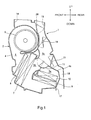
- FIG. 1 to Fig. 4 An example of a vehicle air-conditioning unit 1 according to the present invention is illustrated in Fig. 1 to Fig. 4 .
- the vehicle air-conditioning unit 1 is of a vertical center installation fully-integrated type to be mounted on a center console portion of a vehicle, for example.
- the vehicle air-conditioning unit 1 is arranged on a cabin side of a partitioning plate which partitions an engine room defined in the front of a vehicle traveling direction and the cabin, and basically includes an air conditioning unit body 2 and an intake portion 3.
- the air conditioning unit body 2 stores an air blower 6 for feeding air from the intake portion 3 to a downstream side, a cooling heat exchanger 7 such as an evaporator configured to cool the air fed from the air blower 6, an air filter 8 arranged on an upstream side of the cooling heat exchanger 7, two types of heaters 9, 10 for re-heating the air cooled by the cooling heat exchanger 7, and an air mix door 11 configured to adjust the ratio of air to be fed to the heaters 9, 10 and air to be bypassed in an air flow channel 5 formed in a case 4.
- a dust collecting apparatus using a high voltage, or an ozone generating apparatus using a high voltage may be used although illustration is omitted.
- the air blower 6 in this embodiment includes a fan referred to as a centrifugal multi-blade fan (sirocco fan), and a motor configured to drive the fan, and the motor is arranged by forming an opening portion formed in the case 4 so as to open in a vehicle lateral direction and being inserted on its side therefrom with a drive shaft of the motor extending along the lateral direction of the vehicle.
- a centrifugal multi-blade fan centrifugal multi-blade fan
- the air filter 8 and the cooling heat exchanger 7 are arranged so that all the air introduced from the air blower 6 passes therethrough in the air flow channel 5.
- the cooling heat exchanger 7 is formed, for example, by stacking corrugated fins and tubes alternately by a plurality of layers, includes a tank at a longitudinal end of the tube, and constitutes a freezing cycle by being joined with other air-conditioning apparatuses, which are not illustrated, via piping.
- the air blower 6 is arranged above the cooling heat exchanger 7.
- the heaters 9, 10 arranged on the downstream side of the cooling heat exchanger 7 are a warm water heater 9 located at a position closer to the cooling heat exchanger 7 on the downstream side of the air flow channel 5, and an electric heater 10 located at a position farther from the cooling heat exchanger 7 on the downstream side of the air flow channel 5.
- the warm water heater 9 is formed for example, by stacking the corrugated fins and tubes alternately by a plurality of layers and includes a tank at a longitudinal end of the tube.
- the electric heater 10 is, for example, a PTC heater or the like, and an example of the configuration thereof will be described with reference to Fig. 5 .
- the electric heater 10 illustrated in Fig. 5 includes a heating portion 101 having a heating element 104 arranged between corrugated fins 102 and corrugated fins 103, and a box portion 105 in which high-voltage components for causing the heating element to generate heat are stored, and further includes a cord 106 for supplying electric power to the high-voltage components stored in the box portion 105.
- the heating element 104 is, for example, a PTC semiconductor.
- the air conditioning unit body 2 is provided with a warm air flow channel 5a where the air re-heated by the heaters 9, 10 passes as part of the air flow channel 5 on an upper side in the vehicle vertical direction, which corresponds to the downstream side of the heaters 9, 10, and a cold air flow channel 5b formed on the upper side of the heaters 9, 10 in the vehicle vertical direction and the front side in the vehicle traveling direction on the downstream side of the cooling heat exchanger 7 in the case 4.
- the air mix door 11 is arranged at a joint portion between the warm air flow channel 5a and the cold air flow channel 5b to adjust the ratio between cold air and warm air fed to an air mix chamber 5c on the downstream side of the warm air flow channel 5a and the cold air flow channel 5b.
- the air mix door 11 used in this embodiment is a rotary door.
- a defrost ejection opening 14, a center vent ejection opening 15, side vent ejection openings 16, 16, and a foot ejection opening 17 are opened as needed in the case 4 on the downstream side of the air mix chamber 5c in the air flow channel 5 of the air conditioning unit body 2.
- an air guide channel 18 configured to guide air from the downstream side of the heaters 9, 10 to the foot ejection opening 17 is formed, and the air guide channel 18 is partitioned from a portion where the heaters 9, 10 are stored by a partitioning wall 4a.
- An ejection mode switching door 19 configured to adjust the flow rate of the air directed toward the defrost ejection opening 14 and the vent ejection openings 15, 16 is arranged on the downstream side and the upper side of the air mix chamber 5c of the air flow channel 5 in the vehicle vertical direction
- an ejection mode switching door 20 configured to adjust the rate between the flow rate of the air fed from the defrost ejection opening 14 and the flow rate of the air fed from the vent ejection openings 15, 16 is arranged on the downstream side and the upper side in the vehicle vertical direction of the ejection mode switching door 19.
- the ejection mode switching door 19 is of a butterfly type, and the ejection mode switching door 20 is of a type referred to as a cantilevered, or a flag type. It is true that the arrangement and the type of the ejection mode switching doors 19, 20 are not limited to those illustrated in the drawing and, for example, a defrost ejection mode switching door and a vent ejecting mode switching door may be arranged in the vicinity of respective opening ends of the defrost ejection opening 14 and the vent ejection openings 15, 16.
- An ejection mode switching door 21 configured to adjust the flow rate of the air fed from the foot ejection opening is arranged on the upstream side of the air guide channel 18. In this embodiment, the ejection mode switching door 21 is a butterfly type.
- the intake portion 3 is configured to feed air to the air blower 6 of the air conditioning unit body 2 provided in parallel, and includes an outside air introducing port and an inside air introducing port formed in the case, and an inside-outside air switching door for selecting the outside air introducing port and the inside air introducing port as needed stored in the case.
- a protecting structure 25 is arranged outside the case 4 in a state of surrounding the lower side in the vehicle vertical direction, the both sides in the vehicle lateral direction, and the rear side in the vehicle traveling direction of the electric heater 10.
- the protecting structure 25 in this embodiment includes a lower side protecting member 26, a rear side protecting member 27, a left side protecting member 28, and a right side protecting member 29 as illustrated in Fig. 6 , and the respective protecting members 26, 27, 28, 29 have a plate shape.
- the materials used for the respective protecting members 26, 27, 28, 29 are flexible materials having elasticity (for example, rubber, elastomer), or metals (for example, aluminum alloy, iron, copper, stainless steel) and the like, and from the viewpoint of preventing the protecting structure 25 from being removed accidentally from the case 4 as described later, materials having a certain level of rigidity such as metals are preferable.
- the materials used for the respective protecting members 26, 27, 28, 29 are preferably materials having conductivity.
- the protecting structure 25 When the protecting structure 25 is formed by assembling the protecting members 26, 27, 28, 29, the protecting structure 25 has four surfaces, namely, a lower side surface in the vehicle vertical direction composed of the lower side protecting member 26, a rear side surface in the vehicle traveling direction composed of the rear side protecting member 27, a left side surface in the vehicle lateral direction composed of the left side protecting member 28, and a right side surface in the vehicle lateral direction composed of the right side protecting member 29, and the both side surfaces in the vehicle lateral direction of the protecting structure 25 is in a state of being coupled not only by the rear side surface in the vehicle traveling direction but also by the lower side surface in the vehicle vertical direction.
- the protecting structure 25 even though the vehicle collides and the air-conditioning unit body 2 of the vehicle air-conditioning unit 1 has an impact, the protecting structure 25 exists outside the case 4 of the air-conditioning unit body 2. Therefore, even though the case 4 is broken or deformed, the high-voltage components are prevented from dropping out (down), scattering, and exposed from the case.
- the protecting structure 25 includes the lower side protecting member 26 arranged on the lower side in the case 4 in the vehicle vertical direction, even though the protecting structure 25 has an impact, the left side protecting member 28 and the right side protecting member 29 do not open rearward or forward in the vehicle traveling direction. Therefore, even though the case 4 is broken or deformed, the electric heater 10 is prevented from dropping downward of the vehicle from the case 4 because the lower side protecting member 26 exists.
- the electric heater 10 even though the electric heater 10 is broken by itself and the high-voltage components are exposed from the box portion 105, the electric heater 10 by itself stays within a range surrounded by the protecting structure 25, so that the savers for the passengers, the handlers or the like are prevented from coming into contact with the high-voltage components provided on the electric heater 10 with their fingers or the like. Furthermore, even though the case 4 is completely fragmented and the electric heater 10 and the protecting structure 25 drop out from the position of the vehicle air-conditioning unit 1, since the electric heater 10 is surrounded by the protecting structure 25, which is a frame member, the savers for the passengers or the handlers or the like are prevented from coming into contact with the high-voltage components provided on the electric heater 10 with their fingers or the like.
- the protecting structure 25, however, is not limited to the mode including four protecting members, namely, the lower side protecting member 26, the rear side protecting member 27, the left side protecting member 28, and the right side protecting member 29 as described above.
- a configuration including only one of the lower side protecting member 26, the rear side protecting member 27, the left side protecting member 28, and the right side protecting member 29 illustrated in Fig. 6 a configuration including two protecting members out of the lower side protecting member 26, the rear side protecting member 27, the left side protecting member 28, and the right side protecting member 29 illustrated in Fig.
- the protecting structure 25 is composed of only one protecting member, two protecting members, or three protecting members, by arranging the protecting member on a side opposite to a side of the vehicle where an impact is applied with respect to the electric instrument, the electric instrument is prevented from dropping out, scattering, or exposed from the case.
- the earth circuit 46 is mounted as described above.
- the earth circuit 46 in the mode of the protecting structure 25 having the four protecting members 26, 27, 28, 29 will be described with reference to Fig. 6 and
- the earth circuit 46 illustrated in Fig. 6 and Fig. 7 includes a harness-type earth member 48 configured to couple the electric heater 10 such as a PTC heater and a vehicle body 47 having conductivity such as a metal (the shape of the vehicle body 47 itself is not illustrated), a harness type earth member 49 configured to couple the electric heater 10 and the lower side protecting member 26, a bracket-type earth member 50 configured to couple the rear side protecting member 27 and a cross car beam 56 illustrated only in Fig. 7 , and a harness type earth member 51 configured to couple the rear side protecting member 27 and the vehicle body 47.
- Conductive members are used for the earth members 48, 49, 50, and 51, respectively.
- the earth member 48 is connected at one end thereof to the electric heater 10 and, in this example, is drawn out from between the lower side protecting member 26 and the rear side protecting member 27 to the outer side than the protecting members 26, 27. Furthermore the earth member is provided so as to be drawn along an outer side surface of the rear side protecting member 27 and directed toward the vehicle body 47. By coupling the other end to the vehicle body 47 via a coupler, which is not illustrated, the electric heater 10 and the vehicle body 47 are electrically connected.
- the earth member 48 may be drawn integrally with a power source cable 55 of the electric heater 10.
- the earth member 49 is connected at one end thereof to the electric heater 10 and, in this example, is drawn out from an opening or a gap formed in the the lower side protecting member 26 to the outer side than the lower side protecting member 26.
- the electric heater 10 and the lower side protecting member 26, which is part of the protecting structure 25 are electrically connected.
- the earth member 50 is shaped by bending a metallic plate, and is fixed to the rear side protecting member 27.
- the cross car beam 56 via a coupler, which is not illustrated, the rear side protecting member 27, which is part of the protecting structure 25 and the vehicle body 47 are electrically and mechanically connected.
- the earth member 50 may be manufactured by shaping part of the rear side protecting member 27 as needed.
- the earth member 51 is coupled at one end thereof to the rear side protecting member 27 via a coupler 53 such as a bolt or a screw and, in this example, is provided so as to be drawn together with the earth member 48 on the outside surface of the rear side protecting member 27 and directed toward the vehicle body 47. Then, by coupling the other end to the vehicle body 47 via a coupler, which is not illustrated, the rear side protecting member 27, which is part of the protecting structure 25, and the vehicle body 47 are electrically connected.
- a coupler 53 such as a bolt or a screw
- the electric heater 10 since the electric heater 10 is connected not only with the vehicle body 47 via the earth member 48, but also with the protecting structure 25 via the earth member 49, the function of the earth may be secured even though an electric joint of either one of the earth members is disconnected by an impact caused by a collision of the vehicle.
- the protecting structure 25 is connected not only with the vehicle body 47 via the earth member 50, but also with the vehicle body 47 via the earth member 51, even though an electric joint of either one of the earth members is disconnected by an impact caused by a collision of the vehicle, the function of the earth may be secured.
- the protecting structure 25 including four protecting members 26, 27, 28, 29 by mounting on the case 4 while coupling the protecting members 26, 27, 28, 29 with respect to each other will be described below.
- the protecting member 27 After the protecting member 27 ( second protecting member) has mounted on the case 4, the protecting member 27 is fixed to the case 4 with fastening a screw 31. After the protecting member 28 (third protecting member) has mounted on the case 4, the protecting member 28 is fixed to the case 4 by fastening a screw 31. Then, after the protecting member 29 (fourth protecting member) has mounted on the case 4, the protecting member 29 is fixed to the case 4 by fastening a screw 31. Then, The protecting member 27 and the protecting member 28 are fastened with a fastening bolt 32 illustrated in Fig. 8 , and the protecting member 27 and the protecting member 29 are also fastened with the fastening bolt 32 illustrated in Fig. 8 , so that the protecting member 27 and the protecting members 28, 29 are firmly coupled.
- the protecting member 26 (first protecting member) has mounted on the case 4 from the outer side (lower side) than the protecting members 28, 29, the protecting member 26 and the protecting members 28, 29 are fastened with the fastening bolt 32 illustrated in Fig. 8 , so that the protecting member 26 is fixed to the case 4 via the protecting members 28, 29. Accordingly, the protecting members 26, 27, 28, 29 are mounted to the case 4 while being coupled with each other via the screw 31 and the fastening bolt 32, whereby the protecting structure 25 is formed.
- a groove portion 34 of a head portion 33 of the fastening bolt 32 is preferably formed to have a special shape instead of a groove portion for a cross-slot screwdriver or a groove portion for a flat-blade screwdriver which are normally used. Accordingly, unintentional removal of the protecting members 26, 27, 28, 29 by the user of the vehicle is prevented.
- a structure which can reliably prevent the unintentional removal of the protecting members 26, 27, 28, 29 of the protecting structure 25, which includes the four protecting members 26, 27, 28, 29, a structure illustrated in Fig. 9 and Fig. 10 is used in this embodiment.
- a projecting portion 36 is provided on a surface 41 of the case 4 where the protecting member 28 is mounted
- a projecting portion 37 is provided on a surface 42 of the case 4 where the protecting member 29 is mounted
- a through hole 43 is formed in the protecting member 28 at a position corresponding to the projecting portion 36
- a through hole 44 is formed in the protectingmember 29 at a position corresponding to the projecting portion 37.
- a length L1 from a distal end of the projecting portion 36 of the case 4 in a projecting direction to a distal end of the projecting portion 37 of the case in the projecting direction is set to be larger than a length L2 from an outer surface of the protecting member 28 to an outer surface of the protecting member 29 when the protecting members 26, 27, 28, 29 are assembled to form the protecting structure 25.
- the protecting structure 25 is formed by assembling the protecting members 26, 27, 28, 29 after the through hole 43 of the protecting member 28 has fitted on the projecting portion 36 of the case 4 to mount the protecting member 28 on the case 4, and the through hole 44 of the protecting member 29 has fitted on the projecting portion 37 of the case 4 to mount the protecting member 29 on the case 4, since the through holes 43, 44 of the protecting members 28, 29 are not disconnected from the projecting portions 36, 37 of the case 4, unintentional removal of the protecting structure 25 (protecting members 26, 27, 28, 29) is reliably prevented.
- the electric instrument which is an object to be prevented from being touched by the savers or the handlers by the protecting structure 25 has been described as the electric heater 10 provided with the high-voltage components as an example.
- the invention is not limited thereto, and when the dust collecting apparatus or the ozone generating apparatus using the high voltage is used instead of the air filter 8, the dust collecting apparatus and the ozone generating apparatus are also considered to be the object.
- the protecting structure 25 which is not illustrated, by arranging the protecting member also on the upper side surface of the case 4 in the vehicle vertical direction and coupling the same with the protecting members 26, 27, 28, 29, an increase in strength as the frame member, and an increase in reliability of prevention of scatter of the electric instrument are achieved.
- the earth member 50 has been described as being formed by bending and shaping the metallic plate as an example.
- a harness having conductivity may be used instead.
- the type of the vehicle air-conditioning unit 1 is not limited to the vertical installation fully-integrated type illustrated in Fig. 1 , and a semi-integrated type vehicle air-conditioning unit, which is not illustrated, in which the air blower 6 is offset in the vehicle lateral direction is also applicable.
Landscapes
- Engineering & Computer Science (AREA)
- Physics & Mathematics (AREA)
- Thermal Sciences (AREA)
- Mechanical Engineering (AREA)
- Chemical & Material Sciences (AREA)
- Combustion & Propulsion (AREA)
- General Engineering & Computer Science (AREA)
- Air-Conditioning For Vehicles (AREA)
- Instrument Panels (AREA)
Abstract
Description
- The present invention relates to a vehicle air-conditioning unit configured to be capable of preventing collateral damage that may happen when savers who save passengers of a vehicle after a collision or the like or handlers who perform handling after the collision of the vehicle touch high-voltage components of an electric instrument when the electric instrument such as an electric heating apparatus, a dust collecting apparatus using a high voltage, or an ozone generating apparatus using a high voltage is stored in a case, and a vehicle provided with the vehicle air-conditioning unit.
- In recent years, electric vehicles (EV) and hybrid vehicles are generally used. In such electric vehicles and hybrid vehicles, an electric heating apparatus such as a PTC heater is stored in a case of a vehicle air-conditioning unit instead of or in association with a heating heat exchanger using warm water such as a heater core, for example as described in PTL
- Also, there is a case where a dust collecting apparatus and an ozone generating apparatus using a high voltage are stored in a case of the vehicle air-conditioning unit as described, for example, in
PTL 2 andPTL 3 in order to collect dust contained in air taken from the outside into the vehicle air-conditioning unit by an air blower or to remove odor of the air taken thereto. - High-voltage components are generally provided in a case in order to cause a heat generator to generate heat in the electric heating apparatus described in
PTL 1, for causing corona discharge in the dust collecting apparatus described inPTL 2, and for generating ozone in the ozone generating apparatus described inPTL 3. -
- PTL 1:
JP-A-2000-272332 - PTL 2:
JP-A-2005-334765 - PTL 3:
JP-A-10-76842 - When a vehicle has an impact due to a collision or the like with another vehicle or a construction or the like such as a utility pole, the air-conditioning unit mounted on the vehicle also has an impact, so that a case formed of resin which constitutes an outer shell of the air-conditioning unit may be broken or deformed and, depending on the degree of the impact, the case may be fractured. Simultaneously with the breakage or deformation of the vehicle air-conditioning unit in this manner, the electric heating apparatus, the dust collecting apparatus, and the ozone generating apparatus stored in the case of the air-conditioning unit may also be damaged.
- At this time, high-voltage components that the electric heating apparatus or the like has in the case may be exposed to the outside of the case of the vehicle air-conditioning unit, dropped out from the case, or even disperse in the periphery while maintaining an energized state. Therefore, prevention of a collateral damage that may occur when savers for passengers or handlers touch the high-voltage components in the energized state, which are exposed to the outside of the case, dropped out from the case, or scattered in all directions with their fingers needs to be considered from the safety point of view.
- Accordingly, it is an object of the present invention to provide a vehicle air-conditioning unit configured to be capable of preventing high-voltage components which constitute an electric instrument stored in a case which corresponding to an outer shell of the vehicle air-conditioning unit from being exposed to the outside, dropping out, or scattering from the case even when the case has a significant impact and a vehicle provided with such a vehicle air-conditioning unit.
- A vehicle air-conditioning unit according to the present invention is a vehicle air-conditioning unit in which air is introduced from an outside into a case and air-conditioned air is fed into a cabin with an air blower, and including an electric instrument having high-voltage components and being stored in a case, and is characterized by including a protecting structure configured to prevent the electric instrument from scattering (Claim 1). Here, examples of the electric instrument provided with the high-voltage components include an electric heating apparatus such as a PTC heater, a dust collecting apparatus using a high voltage, and an ozone generating apparatus using a high voltage. Examples of the vehicle air-conditioning unit include a center installation fully-integrated type and a center installation semi-integrated type.
- Accordingly, since the case in which the electric instrument provided with the high-voltage components are stored includes the protecting structure configured to prevent the electric instrument from scattering, even when the case is broken or deformed, the electric instrument is prevented from dropping out, scattering or being exposed from the case because the protecting structure configured to protect the electric instrument provided with the high-voltage components is provided separately from the case.
- The vehicle air-conditioning unit of the present invention is characterized in that the protecting structure is arranged outside the case (Claim 2). Accordingly, the protecting structure may be mounted after the manufacture of the case, and may be mounted easily in a direction in which dropping out, scatter, or exposure of the electric instrument out of the case is supposed.
- The vehicle air-conditioning unit of the present invention is characterized in that the protecting structure is formed of a conductive material, and is provided with an earth circuit mounted thereon (Claim 3). Accordingly, an electric circuit for grounding of the electric instrument may be provided via the protecting structure, so that the safety of passengers, savers for the passengers, and handlers may be enhanced.
- The vehicle air-conditioning unit of the present invention is characterized in that the protecting structure is formed of a plate-shaped member (Claim 4). In other words, each of protecting members is formed of a plate-shaped member. Accordingly, contact of fingers of the passengers, the savers for the passengers, the handlers, and the like to the high-voltage components of the electric instrument is prevented by itself, so that a collateral damage caused by contact of the passenger, the saver for the passengers, the handlers, and the like with the high-voltage components of the electric instrument is prevented.
- The vehicle air-conditioning unit of the present invention is characterized in that the protecting structure is formed of a flexible member (Claim 5). In other words, each of protecting members is formed of a flexible material. The flexible material includes elastic synthetic resin materials such as wires or rubbers. Accordingly, even when the protecting structure has a significant impact, the impact can be absorbed, so that the protecting structure is prevented from becoming damaged by the impact exerted to the vehicle.
- The vehicle air-conditioning unit according to the present invention is characterized in that the protecting structure is composed of any one of a lower side protecting member arranged on a lower side of the electric instrument in a vehicle vertical direction, a rear side protecting member arranged on a rear side of the electric instrument in a vehicle fore-and-aft direction, a left side protecting member arranged on a left side of the electric instrument in a vehicle lateral direction, and a right side protecting member arranged on a right side of the electric instrument (Claim 6). In other words, only the lower side protecting member, the rear side protecting member, the left side protecting member, or the right side protecting member may be used as the protecting structure.
- Accordingly, by arranging the protecting structure on a side opposite to a side of the vehicle where an impact is applied with respect to the electric instrument, even when the protecting structure is composed of any one of the lower side protecting member, the right side protecting member, the left side protecting member, or the rear side protecting member, the electric instrument is prevented from dropping out, scattering, or exposed from the case.
- The vehicle air-conditioning unit according to the present invention is characterized in that the protecting structure is composed of at least two or more of the lower side protecting member arranged on a lower side of the electric instrument in a vehicle vertical direction, the rear side protecting member arranged on a rear side of the electric instrument in a vehicle fore-and-aft direction, the left side protecting member arranged on a left side of the electric instrument in a vehicle lateral direction, and the right side protecting member arranged on a right side of the electric instrument, and in that a plurality of the protecting members are formed by being integrally coupled. (Claim 7). Examples of coupling of the plurality of protecting members include coupling of the two adjacent protecting members such as the lower side protecting member and the rear side protecting member, or the lower side protecting member and the right side protecting member, coupling of three protecting members such as the lower side protecting member, the right side protecting member, and the left side protecting member, or coupling of four protecting members such as the lower side protecting member, the right side protecting member, the left side protecting member, and the rear side protecting member.
- In this manner, since the surface of the protecting structure that protects the electric instrument is increased by configuring the protecting structure with two or more of the lower side protecting member, the right side protecting member, the left side protecting member, and the rear side protecting member, even when the case is broken or deformed due to an impact on the vehicle, the electric instrument is prevented from dropping out, scattering, or exposed from the case further reliably.
- In particular, in a case where the protecting structure is formed by coupling four protecting members, namely, the lower side protecting member, the right side protecting member, the left side protect ing member, and the rear side protect ing member, even when not only a bottom portion, but also the entire or a major part of the case are broken or deformed by the impact exerted to the vehicle from the front in the vehicle traveling direction, the high-voltage components of the electric instrument are prevented from scattering rearward of the vehicle traveling direction. The protecting structure formed by coupling the four protecting members, namely, the lower side protecting member, the right side protecting member, the left side protecting member, and the rear side protecting member has a certain extent of strength as a frame-shaped structure when a material having relatively high rigidity is used for the respective protecting members because the respective protecting members are integrally coupled, whereby a possibility that one of the both side surfaces of the protecting structure in the vehicle lateral direction is opened due to the impact exerted to the vehicle is avoided, so that scatter or exposure of the electric instrument may be prevented further reliably.
- The vehicle air-conditioning unit of the present invention is characterized in that the protecting structure is formed by mounting the lower side protecting member, the rear side protecting member, the left side protecting member, and the right side protecting member respectively to the case, and then coupling the four protecting members to each other, the case is formed with projections on two or more surfaces of four surfaces thereof opposing four surf aces of the protecting structure, the protecting structure is provided with through holes at positions corresponding to the projections, the projections and the through holes are fitted to each other when the four protecting members are mounted on the case, and a length from a distal end of one of the projections to a distal end of the other projection is longer than a length between opening edges of the two through holes to which the two projections are fitted (Claim 8) . Accordingly, unintentional removal of the protecting members in a case where a user of the vehicle does maintenance by him/herself is prevented.
- The vehicle includes the vehicle air-conditioning unit according to
Claim 1 to Claim 8 (Claim 9). Accordingly, a vehicle capable of preventing the high-voltage components which constitute the electric instrument stored in a case from dropping out, or scattering, or being exposed to the outside from the case even when the case which constitutes an outer shell of the air-conditioning unit has a significant impact is provided. - As described above, according to the invention described in
Claim 1 toClaim 9, since the case in which the electric instrument provided with the high-voltage components is stored includes the protecting structure configured to prevent the electric instrument from scattering, even when the case is broken or deformed, the electric instrument may be prevented from dropping out, or scattering from the case because the protecting structure configured to protect the electric instrument provided with the high-voltage components is provided separately from the case. - In particular, according to the invention described in
Claim 2, since the protecting structure is arranged outside of the case, the protecting structure may be mounted after the manufacture of the case, and may be mounted easily in the direction in which dropping out, scatter, or exposure of the electric instrument out of the case is supposed. - In particular, according to the invention described in
Claim 3, the electric circuit for grounding of the electric instrument may be provided via the protecting structure, so that the safety of the passengers, the savers for the passengers, and the handlers may be enhanced. - In particular, according to the invention described in
Claim 4, contact of the passengers, the savers for the passengers, and the handlers with the high-voltage components with their fingers may be prevented further effectively and further reliably. - In particular, according to the invention described in
Claim 5, even when the protecting structure has a significant impact, the impact can be absorbed, so that the protecting structure may be prevented from becoming damaged by the impact exerted to the vehicle. - In particular, according to the invention described in
Claim 6, by arranging the protecting member on a side opposite to a side of the vehicle where an impact is applied with respect to the electric instrument, even when the protecting structure is composed of one of the lower side protecting member, the right side protecting member, the left side protecting member, or the rear side protecting member, the electric instrument may be prevented from dropping out, scattering, or exposed from the case. - In particular, according to the invention described in
Claim 7, since the surface of the protecting structure that protects the electric instrument is increased by configuring the protecting structure with two or more of the lower side protecting member, the right side protecting member, the left side protecting member, and the rear side protecting member, even when the case is broken or deformed due to an impact on the vehicle, the electric instrument is prevented from dropping out, scattering, or exposed from the case further reliably. - In addition, in a case where the protecting structure is formed by coupling four protecting members, namely, the lower side protecting member, the right side protecting member, the left side protect ing member, and the rear side protect ing member, even when not only a bottom portion, but also the entire or a major part of the case are broken or deformed by the impact exerted to the vehicle from the front in the traveling direction, the high-voltage components of the electric instrument may be prevented from scattering rearward of the vehicle traveling direction. The protecting structure formed by coupling the four protecting members, namely, the lower side protecting member, the right side protecting member, the left side protecting member, and the rear side protecting member has a certain extent of strength as a frame-shaped structure when a material having relatively high rigidity is used for the respective protecting members because the respective protecting members are integrally coupled, whereby a possibility that one of the both side surfaces of the protecting structure in the vehicle lateral direction is opened due to the impact exerted to the vehicle is avoided, so that scatter or exposure of the electric instrument may be prevented further reliably.
- In particular, according to the invention described in
Claim 8, unintentional removal of the protecting structure in a case where a user of the vehicle does maintenance by him/herself may be prevented. - In particular, according to the invention described in
Claim 9, a vehicle capable of preventing the high-voltage components which constitute the electric instrument stored in a case from dropping out, or scattering, or being exposed to the outside from the case even when the case which constitutes an outer shell of the air-conditioning unit has a significant impact may be provided. -
- [
Fig. 1] Fig. 1 is a cross-sectional view illustrating a schematic configuration of an air conditioning unit body of a vehicle air-conditioning unit of a center installation fully-integrated type as an example of the vehicle air-conditioning unit of the present invention. - [
Fig. 2] Fig. 2 is an explanatory drawing illustrating positions of storage of a protecting structure and an electric heater in a state of viewing the vehicle air-conditioning unit described above from the rear on the obliquely left side in a vehicle traveling direction. - [
Fig. 3] Fig. 3 is an explanatory drawing illustrating positions of storage of the protecting structure and the electric heater in a state of viewing the vehicle air-conditioning unit described above from the rear on the obliquely right side in the vehicle traveling direction. - [
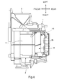
Fig. 4] Fig. 4 is an explanatory drawing illustrating positions of storage of the protecting structure and the electric heater in a state of viewing the vehicle air-conditioning unit described above from below in a vehicle vertical direction. - [
Fig. 5] Fig. 5 is an explanatory drawing illustrating an example of the electric heater stored in a case of the vehicle air-conditioning unit. - [
Fig. 6] Fig. 6 is an explanatory drawing illustrating structures of respective protecting members in a lower side portion of the vehicle air-conditioning unit described above, and a state in which the respective protecting members are mounted on the case to form the protecting structure. - [
Fig. 7] Fig. 7A illustrates a state in which an earth circuit is mounted on the protecting structure, andFig. 7B is a schematic drawing of the earth circuit. - [
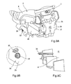
Fig. 8] Fig. 8A is a schematic drawing illustrating a state in which the protecting members are coupled to each other via a coupler, andFig. 8B is an explanatory drawing illustrating specifically a structure of a groove portion at a distal end of the coupler for coupling the protecting members to each other. - [
Fig. 9] Fig. 9A is an explanatory drawing illustrating a structure for mounting the protecting member to the case on the lower side portion of the vehicle air-conditioning unit described above,Fig. 9B is an explanatory drawing illustrating a state in which a projecting portion of the protecting member is inserted into a through hole of the case, andFig. 9C is an explanatory drawing illustrating a form of the projecting portion formed on the protecting member. - [
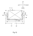
Fig. 10] Fig. 10 is a schematic drawing illustrating the fact that the length between the distal ends of the projecting portions of the case is longer than a length between outer surfaces of the protecting members. - Hereinafter, embodiments of the present invention will be described with reference to attached drawings.
- An example of a vehicle air-
conditioning unit 1 according to the present invention is illustrated inFig. 1 to Fig. 4 . The vehicle air-conditioning unit 1 is of a vertical center installation fully-integrated type to be mounted on a center console portion of a vehicle, for example. The vehicle air-conditioning unit 1 is arranged on a cabin side of a partitioning plate which partitions an engine room defined in the front of a vehicle traveling direction and the cabin, and basically includes an airconditioning unit body 2 and anintake portion 3. - The air
conditioning unit body 2 stores anair blower 6 for feeding air from theintake portion 3 to a downstream side, acooling heat exchanger 7 such as an evaporator configured to cool the air fed from theair blower 6, anair filter 8 arranged on an upstream side of thecooling heat exchanger 7, two types ofheaters cooling heat exchanger 7, and anair mix door 11 configured to adjust the ratio of air to be fed to theheaters air flow channel 5 formed in acase 4. Instead of theair filter 8, a dust collecting apparatus using a high voltage, or an ozone generating apparatus using a high voltage may be used although illustration is omitted. - The
air blower 6 in this embodiment includes a fan referred to as a centrifugal multi-blade fan (sirocco fan), and a motor configured to drive the fan, and the motor is arranged by forming an opening portion formed in thecase 4 so as to open in a vehicle lateral direction and being inserted on its side therefrom with a drive shaft of the motor extending along the lateral direction of the vehicle. - The
air filter 8 and thecooling heat exchanger 7 are arranged so that all the air introduced from theair blower 6 passes therethrough in theair flow channel 5. Thecooling heat exchanger 7 is formed, for example, by stacking corrugated fins and tubes alternately by a plurality of layers, includes a tank at a longitudinal end of the tube, and constitutes a freezing cycle by being joined with other air-conditioning apparatuses, which are not illustrated, via piping. In this embodiment, theair blower 6 is arranged above thecooling heat exchanger 7. - The
heaters cooling heat exchanger 7 are awarm water heater 9 located at a position closer to thecooling heat exchanger 7 on the downstream side of theair flow channel 5, and anelectric heater 10 located at a position farther from thecooling heat exchanger 7 on the downstream side of theair flow channel 5. Thewarm water heater 9 is formed for example, by stacking the corrugated fins and tubes alternately by a plurality of layers and includes a tank at a longitudinal end of the tube. - The
electric heater 10 is, for example, a PTC heater or the like, and an example of the configuration thereof will be described with reference toFig. 5 . Theelectric heater 10 illustrated inFig. 5 includes aheating portion 101 having aheating element 104 arranged betweencorrugated fins 102 andcorrugated fins 103, and abox portion 105 in which high-voltage components for causing the heating element to generate heat are stored, and further includes acord 106 for supplying electric power to the high-voltage components stored in thebox portion 105. Theheating element 104 is, for example, a PTC semiconductor. - In addition, the air
conditioning unit body 2 is provided with a warmair flow channel 5a where the air re-heated by theheaters air flow channel 5 on an upper side in the vehicle vertical direction, which corresponds to the downstream side of theheaters air flow channel 5b formed on the upper side of theheaters cooling heat exchanger 7 in thecase 4. Theair mix door 11 is arranged at a joint portion between the warmair flow channel 5a and the coldair flow channel 5b to adjust the ratio between cold air and warm air fed to anair mix chamber 5c on the downstream side of the warmair flow channel 5a and the coldair flow channel 5b. Theair mix door 11 used in this embodiment is a rotary door. - Furthermore, a defrost ejection opening 14, a center vent ejection opening 15, side
vent ejection openings case 4 on the downstream side of theair mix chamber 5c in theair flow channel 5 of the airconditioning unit body 2. In this embodiment, anair guide channel 18 configured to guide air from the downstream side of theheaters air guide channel 18 is partitioned from a portion where theheaters partitioning wall 4a. - An ejection
mode switching door 19 configured to adjust the flow rate of the air directed toward the defrost ejection opening 14 and thevent ejection openings air mix chamber 5c of theair flow channel 5 in the vehicle vertical direction, and an ejectionmode switching door 20 configured to adjust the rate between the flow rate of the air fed from the defrost ejection opening 14 and the flow rate of the air fed from thevent ejection openings mode switching door 19. In this embodiment, the ejectionmode switching door 19 is of a butterfly type, and the ejectionmode switching door 20 is of a type referred to as a cantilevered, or a flag type. It is true that the arrangement and the type of the ejectionmode switching doors vent ejection openings mode switching door 21 configured to adjust the flow rate of the air fed from the foot ejection opening is arranged on the upstream side of theair guide channel 18. In this embodiment, the ejectionmode switching door 21 is a butterfly type. - The
intake portion 3 is configured to feed air to theair blower 6 of the airconditioning unit body 2 provided in parallel, and includes an outside air introducing port and an inside air introducing port formed in the case, and an inside-outside air switching door for selecting the outside air introducing port and the inside air introducing port as needed stored in the case. - As illustrated in
Fig. 2 to Fig. 4 , in the vehicle air-conditioning unit 1 in this embodiment, a protectingstructure 25 is arranged outside thecase 4 in a state of surrounding the lower side in the vehicle vertical direction, the both sides in the vehicle lateral direction, and the rear side in the vehicle traveling direction of theelectric heater 10. - The protecting
structure 25 in this embodiment includes a lowerside protecting member 26, a rearside protecting member 27, a leftside protecting member 28, and a rightside protecting member 29 as illustrated inFig. 6 , and the respective protectingmembers members structure 25 from being removed accidentally from thecase 4 as described later, materials having a certain level of rigidity such as metals are preferable. For the reliable protection of the passengers, the savers for the passengers, and the handlers, mounting of anearth circuit 46 as described later on the protectingstructure 25 is conceivable. In this case, the materials used for the respective protectingmembers - When the protecting
structure 25 is formed by assembling the protectingmembers structure 25 has four surfaces, namely, a lower side surface in the vehicle vertical direction composed of the lowerside protecting member 26, a rear side surface in the vehicle traveling direction composed of the rearside protecting member 27, a left side surface in the vehicle lateral direction composed of the leftside protecting member 28, and a right side surface in the vehicle lateral direction composed of the rightside protecting member 29, and the both side surfaces in the vehicle lateral direction of the protectingstructure 25 is in a state of being coupled not only by the rear side surface in the vehicle traveling direction but also by the lower side surface in the vehicle vertical direction. - According to the configuration of the protecting
structure 25 as described above, even though the vehicle collides and the air-conditioning unit body 2 of the vehicle air-conditioning unit 1 has an impact, the protectingstructure 25 exists outside thecase 4 of the air-conditioning unit body 2. Therefore, even though thecase 4 is broken or deformed, the high-voltage components are prevented from dropping out (down), scattering, and exposed from the case. - In particular, since the protecting
structure 25 includes the lowerside protecting member 26 arranged on the lower side in thecase 4 in the vehicle vertical direction, even though the protectingstructure 25 has an impact, the leftside protecting member 28 and the rightside protecting member 29 do not open rearward or forward in the vehicle traveling direction. Therefore, even though thecase 4 is broken or deformed, theelectric heater 10 is prevented from dropping downward of the vehicle from thecase 4 because the lowerside protecting member 26 exists. Therefore, even though theelectric heater 10 is broken by itself and the high-voltage components are exposed from thebox portion 105, theelectric heater 10 by itself stays within a range surrounded by the protectingstructure 25, so that the savers for the passengers, the handlers or the like are prevented from coming into contact with the high-voltage components provided on theelectric heater 10 with their fingers or the like. Furthermore, even though thecase 4 is completely fragmented and theelectric heater 10 and the protectingstructure 25 drop out from the position of the vehicle air-conditioning unit 1, since theelectric heater 10 is surrounded by the protectingstructure 25, which is a frame member, the savers for the passengers or the handlers or the like are prevented from coming into contact with the high-voltage components provided on theelectric heater 10 with their fingers or the like. - The protecting
structure 25, however, is not limited to the mode including four protecting members, namely, the lowerside protecting member 26, the rearside protecting member 27, the leftside protecting member 28, and the rightside protecting member 29 as described above. In other words, a configuration including only one of the lowerside protecting member 26, the rearside protecting member 27, the leftside protecting member 28, and the rightside protecting member 29 illustrated inFig. 6 , a configuration including two protecting members out of the lowerside protecting member 26, the rearside protecting member 27, the leftside protecting member 28, and the rightside protecting member 29 illustrated inFig. 6 (for example, a combination of the lowerside protecting member 26 and the rear side protecting member 27), or a configuration including three protecting members out of the lowerside protecting member 26, the rearside protecting member 27, the leftside protecting member 28, and the rightside protecting member 29 illustrated inFig. 6 (for example, a combination of the lowerside protecting member 26, the leftside protecting member 28, and the right side protecting member 29) are applicable. - In this manner even when the protecting
structure 25 is composed of only one protecting member, two protecting members, or three protecting members, by arranging the protecting member on a side opposite to a side of the vehicle where an impact is applied with respect to the electric instrument, the electric instrument is prevented from dropping out, scattering, or exposed from the case. - In the case where the protecting
structure 25 is formed of a material having conductivity, theearth circuit 46 is mounted as described above. Theearth circuit 46 in the mode of the protectingstructure 25 having the four protectingmembers Fig. 6 and -
Fig. 7 . - The
earth circuit 46 illustrated inFig. 6 andFig. 7 includes a harness-type earth member 48 configured to couple theelectric heater 10 such as a PTC heater and avehicle body 47 having conductivity such as a metal (the shape of thevehicle body 47 itself is not illustrated), a harnesstype earth member 49 configured to couple theelectric heater 10 and the lowerside protecting member 26, a bracket-type earth member 50 configured to couple the rearside protecting member 27 and across car beam 56 illustrated only inFig. 7 , and a harnesstype earth member 51 configured to couple the rearside protecting member 27 and thevehicle body 47. Conductive members are used for theearth members - The
earth member 48 is connected at one end thereof to theelectric heater 10 and, in this example, is drawn out from between the lowerside protecting member 26 and the rearside protecting member 27 to the outer side than the protectingmembers side protecting member 27 and directed toward thevehicle body 47. By coupling the other end to thevehicle body 47 via a coupler, which is not illustrated, theelectric heater 10 and thevehicle body 47 are electrically connected. Theearth member 48 may be drawn integrally with apower source cable 55 of theelectric heater 10. Theearth member 49 is connected at one end thereof to theelectric heater 10 and, in this example, is drawn out from an opening or a gap formed in the the lowerside protecting member 26 to the outer side than the lowerside protecting member 26. Then, by coupling the other end to the lowerside protecting member 26 via acoupler 52 such as a bolt or a screw, theelectric heater 10 and the lowerside protecting member 26, which is part of the protectingstructure 25 are electrically connected. Theearth member 50 is shaped by bending a metallic plate, and is fixed to the rearside protecting member 27. Then, by coupling to thecross car beam 56 via a coupler, which is not illustrated, the rearside protecting member 27, which is part of the protectingstructure 25 and thevehicle body 47 are electrically and mechanically connected. Theearth member 50, however, may be manufactured by shaping part of the rearside protecting member 27 as needed. Theearth member 51 is coupled at one end thereof to the rearside protecting member 27 via acoupler 53 such as a bolt or a screw and, in this example, is provided so as to be drawn together with theearth member 48 on the outside surface of the rearside protecting member 27 and directed toward thevehicle body 47. Then, by coupling the other end to thevehicle body 47 via a coupler, which is not illustrated, the rearside protecting member 27, which is part of the protectingstructure 25, and thevehicle body 47 are electrically connected. - Accordingly, since the
electric heater 10 is connected not only with thevehicle body 47 via theearth member 48, but also with the protectingstructure 25 via theearth member 49, the function of the earth may be secured even though an electric joint of either one of the earth members is disconnected by an impact caused by a collision of the vehicle. - The protecting
structure 25 is connected not only with thevehicle body 47 via theearth member 50, but also with thevehicle body 47 via theearth member 51, even though an electric joint of either one of the earth members is disconnected by an impact caused by a collision of the vehicle, the function of the earth may be secured. - In this manner, since a plurality of earth circuits are provided respectively on the
electric heater 10 and the protectingstructure 25, collateral damage of the passengers, the savers for the passengers, and the handlers may be prevented reliably. - Subsequently, a procedure to form the protecting
structure 25 including four protectingmembers case 4 while coupling the protectingmembers - After the protecting member 27 ( second protecting member) has mounted on the
case 4, the protectingmember 27 is fixed to thecase 4 with fastening ascrew 31. After the protecting member 28 (third protecting member) has mounted on thecase 4, the protectingmember 28 is fixed to thecase 4 by fastening ascrew 31. Then, after the protecting member 29 (fourth protecting member) has mounted on thecase 4, the protectingmember 29 is fixed to thecase 4 by fastening ascrew 31. Then, The protectingmember 27 and the protectingmember 28 are fastened with afastening bolt 32 illustrated inFig. 8 , and the protectingmember 27 and the protectingmember 29 are also fastened with thefastening bolt 32 illustrated inFig. 8 , so that the protectingmember 27 and the protectingmembers case 4 from the outer side (lower side) than the protectingmembers member 26 and the protectingmembers fastening bolt 32 illustrated inFig. 8 , so that the protectingmember 26 is fixed to thecase 4 via the protectingmembers members case 4 while being coupled with each other via thescrew 31 and thefastening bolt 32, whereby the protectingstructure 25 is formed. - A
groove portion 34 of ahead portion 33 of thefastening bolt 32 is preferably formed to have a special shape instead of a groove portion for a cross-slot screwdriver or a groove portion for a flat-blade screwdriver which are normally used. Accordingly, unintentional removal of the protectingmembers - Furthermore, as a structure which can reliably prevent the unintentional removal of the protecting
members structure 25, which includes the four protectingmembers Fig. 9 andFig. 10 is used in this embodiment. - In other words, a projecting
portion 36 is provided on asurface 41 of thecase 4 where the protectingmember 28 is mounted, a projectingportion 37 is provided on asurface 42 of thecase 4 where the protectingmember 29 is mounted, and a throughhole 43 is formed in the protectingmember 28 at a position corresponding to the projectingportion 36, and a throughhole 44 is formed in theprotectingmember 29 at a position corresponding to the projectingportion 37. A length L1 from a distal end of the projectingportion 36 of thecase 4 in a projecting direction to a distal end of the projectingportion 37 of the case in the projecting direction is set to be larger than a length L2 from an outer surface of the protectingmember 28 to an outer surface of the protectingmember 29 when the protectingmembers structure 25. - Accordingly, in the case where the protecting
structure 25 is formed by assembling the protectingmembers hole 43 of the protectingmember 28 has fitted on the projectingportion 36 of thecase 4 to mount the protectingmember 28 on thecase 4, and the throughhole 44 of the protectingmember 29 has fitted on the projectingportion 37 of thecase 4 to mount the protectingmember 29 on thecase 4, since the throughholes members portions case 4, unintentional removal of the protecting structure 25 (protectingmembers - By fitting the through
holes portions members case 4 is also achieved. - With the configuration described above, the electric instrument which is an object to be prevented from being touched by the savers or the handlers by the protecting
structure 25 has been described as theelectric heater 10 provided with the high-voltage components as an example. However, the invention is not limited thereto, and when the dust collecting apparatus or the ozone generating apparatus using the high voltage is used instead of theair filter 8, the dust collecting apparatus and the ozone generating apparatus are also considered to be the object. - By forming the protecting
structure 25, which is not illustrated, by arranging the protecting member also on the upper side surface of thecase 4 in the vehicle vertical direction and coupling the same with the protectingmembers - Furthermore, the
earth member 50 has been described as being formed by bending and shaping the metallic plate as an example. However, a harness having conductivity may be used instead. - Finally, the type of the vehicle air-
conditioning unit 1 is not limited to the vertical installation fully-integrated type illustrated inFig. 1 , and a semi-integrated type vehicle air-conditioning unit, which is not illustrated, in which theair blower 6 is offset in the vehicle lateral direction is also applicable. -
- 1
- vehicle air-conditioning unit
- 2
- air conditioning unit body
- 4
- case
- 5
- air flow channel
- 6
- air blower
- 10
- electric heater
- 25
- protecting structure
- 26
- lower side protecting member
- 27
- rear side protecting member
- 28
- left side protecting member
- 29
- right side protecting member
- 36
- projecting portion
- 37
- projecting portion
- 43
- through hole
- 44
- through hole
- 46
- earth circuit
- 105
- box portion of electric heater
Claims (9)
- A vehicle air-conditioning unit in which air is introduced from an outside into a case and air-conditioned air is fed into a cabin with an air blower, and including an electric instrument having high-voltage components and being stored in the case comprising:a protecting structure configured to prevent the electric instrument from scattering.
- The vehicle air-conditioning unit according to Claim 1, wherein the protecting structure is arranged outside the case.
- The vehicle air-conditioning unit according to Claim 1 or Claim 2, wherein the protecting structure is formed of a conductive material, and is provided with an earth circuit mounted thereon.
- The vehicle air-conditioning unit according to any one of Claim 1 to Claim 3, wherein the protecting structure is formed of a plate-shaped member.
- The vehicle air-conditioning unit according to any one of Claim 1 to Claim 3, wherein the protecting structure is formed of a flexible member.
- The vehicle air-conditioning unit according to any one of Claim 1 to Claim 5, wherein the protecting structure is composed of any one of a lower side protecting member arranged on a lower side of the electric instrument in a vehicle vertical direction, a rear side protecting member arranged on a rear side of the electric instrument in a vehicle fore-and-aft direction, a left side protecting member arranged on a left side of the electric instrument in a vehicle lateral direction, and a right side protecting member arranged on a right side of the electric instrument.
- The vehicle air-conditioning unit according to any one of Claim 1 to Claim 5, wherein the protecting structure is composed of at least two or more of a lower side protecting member arranged on a lower side of the electric instrument in a vehicle vertical direction, a rear side protecting member arranged on a rear side of the electric instrument in a vehicle fore-and-aft direction, a left side protecting member arranged on a left side of the electric instrument in a vehicle lateral direction, and a right side protecting member arranged on a right side of the electric instrument, and wherein a plurality of the protecting members are formed by being integrally coupled.
- The vehicle air-conditioning unit according to Claim 7, wherein the protecting structure is formed by mounting the lower side protecting member, the rear side protecting member, the left side protecting member, and the right side protecting member respectively to the case, and then coupling the four protecting members to each other,
the case is formed with projections on two or more surfaces of four surfaces thereof opposing four surf aces of the protecting structure,
the protecting structure is provided with through holes at positions corresponding to the projections, the projections and the through holes are fitted to each other when the four protecting members are mounted on the case, and
a length from a distal end of one of the projections to a distal end of the other projection is longer than a length between opening edges of the two through holes to which the two projections are fitted. - A vehicle comprising the vehicle air-conditioning unit according to Claim 1 to Claim 8.
Applications Claiming Priority (2)
| Application Number | Priority Date | Filing Date | Title |
|---|---|---|---|
| JP2012010185 | 2012-01-20 | ||
| PCT/JP2013/050647 WO2013108774A1 (en) | 2012-01-20 | 2013-01-16 | Vehicle air-conditioning unit and vehicle |
Publications (3)
| Publication Number | Publication Date |
|---|---|
| EP2813383A1 true EP2813383A1 (en) | 2014-12-17 |
| EP2813383A4 EP2813383A4 (en) | 2016-06-22 |
| EP2813383B1 EP2813383B1 (en) | 2018-10-03 |
Family
ID=48799199
Family Applications (1)
| Application Number | Title | Priority Date | Filing Date |
|---|---|---|---|
| EP13738117.4A Active EP2813383B1 (en) | 2012-01-20 | 2013-01-16 | Vehicle air-conditioning unit and vehicle |
Country Status (7)
| Country | Link |
|---|---|
| US (1) | US9321324B2 (en) |
| EP (1) | EP2813383B1 (en) |
| JP (1) | JP5866698B2 (en) |
| CN (1) | CN104039571B (en) |
| BR (1) | BR112014017912B8 (en) |
| ES (1) | ES2703394T3 (en) |
| WO (1) | WO2013108774A1 (en) |
Families Citing this family (9)
| Publication number | Priority date | Publication date | Assignee | Title |
|---|---|---|---|---|
| CN104470740B (en) * | 2012-07-09 | 2016-08-17 | 汉拿伟世通空调有限公司 | vehicle heater |
| CN109334394A (en) * | 2015-01-06 | 2019-02-15 | 翰昂汽车零部件有限公司 | Air supply device for vehicle air conditioning system including electrostatic precipitator and control method thereof |
| DE102016000385A1 (en) * | 2016-01-15 | 2017-07-20 | Paragon Ag | Device for separating ultrafine particles (UFP) from a flow of air flowing in motor vehicle ventilation and air conditioning systems |
| JP6609853B2 (en) * | 2016-12-27 | 2019-11-27 | 本田技研工業株式会社 | Vehicle air-conditioning unit mounting structure |
| US10882378B2 (en) * | 2017-08-18 | 2021-01-05 | Zhejiang CFMOTO Power Co., Ltd. | ATV air heat exchanger with mounting structure and linkage |
| KR102401277B1 (en) * | 2017-09-25 | 2022-05-25 | 한온시스템 주식회사 | Air conditioner for vehicle |
| JP7221886B2 (en) | 2020-01-17 | 2023-02-14 | トヨタ自動車株式会社 | electric vehicle |
| CN111503034B (en) * | 2020-05-28 | 2025-10-28 | 深圳市百越汽车科技有限公司 | A new blower without negative terminal |
| FR3158151B1 (en) * | 2024-01-08 | 2026-01-23 | Valeo Systemes Thermiques | Multifunctional support for a thermal management module |
Family Cites Families (20)
| Publication number | Priority date | Publication date | Assignee | Title |
|---|---|---|---|---|
| US3469073A (en) * | 1964-06-22 | 1969-09-23 | Gen Motors Corp | Electrical system |
| US3424263A (en) * | 1966-09-28 | 1969-01-28 | Enoch Black | Safety steering column |
| JPS625406Y2 (en) * | 1980-01-24 | 1987-02-06 | ||
| EP0492786A3 (en) * | 1990-12-24 | 1993-11-18 | Ford Motor Co | Reversible attachment of members using dielectric heating |
| JPH07108816A (en) * | 1993-10-15 | 1995-04-25 | Matsushita Electric Ind Co Ltd | Air conditioner for vehicle |
| DE19607122A1 (en) * | 1996-02-26 | 1997-08-28 | Suetrak Transportkaelte | Heating device |
| JP3700275B2 (en) * | 1996-08-27 | 2005-09-28 | 株式会社デンソー | Resin molded products for vehicles |
| JP3382789B2 (en) | 1996-09-05 | 2003-03-04 | 三菱重工業株式会社 | Vehicle air conditioner |
| JP2000272332A (en) | 1999-03-24 | 2000-10-03 | Bosch Automotive Systems Corp | Air conditioner for automobile |
| JP2001001751A (en) | 1999-06-24 | 2001-01-09 | Denso Corp | Air conditioner |
| JP2004142587A (en) * | 2002-10-24 | 2004-05-20 | Mitsubishi Heavy Ind Ltd | Vehicle air conditioner |
| WO2005021334A1 (en) * | 2003-08-25 | 2005-03-10 | Cascade Engineering, Inc. | Dashmat with component bridge |
| JP4382511B2 (en) * | 2004-02-05 | 2009-12-16 | パイオニア株式会社 | Conduction device |
| JP4075831B2 (en) * | 2004-03-24 | 2008-04-16 | 株式会社デンソー | Air conditioner for vehicles |
| JP2005334765A (en) | 2004-05-26 | 2005-12-08 | Denso Corp | Air cleaner |
| DE102005032251A1 (en) * | 2005-07-09 | 2007-01-18 | Deere & Company, Moline | Housing of an air conditioner |
| JP5173374B2 (en) * | 2007-11-28 | 2013-04-03 | 三菱重工業株式会社 | Electric compressor for in-vehicle air conditioner |
| DE102009057870B4 (en) * | 2009-12-11 | 2025-08-14 | Mahle International Gmbh | Automotive air conditioning |
| CN101913314B (en) * | 2010-07-30 | 2012-05-23 | 奇瑞汽车股份有限公司 | Air conditioning system of electric automobile and control method thereof |
| JP2012144173A (en) * | 2011-01-13 | 2012-08-02 | Calsonic Kansei Corp | Air conditioner for vehicle |
-
2013
- 2013-01-16 WO PCT/JP2013/050647 patent/WO2013108774A1/en not_active Ceased
- 2013-01-16 BR BR112014017912A patent/BR112014017912B8/en active IP Right Grant
- 2013-01-16 EP EP13738117.4A patent/EP2813383B1/en active Active
- 2013-01-16 US US14/372,904 patent/US9321324B2/en active Active
- 2013-01-16 CN CN201380004875.2A patent/CN104039571B/en active Active
- 2013-01-16 JP JP2013554302A patent/JP5866698B2/en active Active
- 2013-01-16 ES ES13738117T patent/ES2703394T3/en active Active
Also Published As
| Publication number | Publication date |
|---|---|
| JPWO2013108774A1 (en) | 2015-05-11 |
| EP2813383B1 (en) | 2018-10-03 |
| EP2813383A4 (en) | 2016-06-22 |
| BR112014017912B8 (en) | 2022-06-14 |
| WO2013108774A1 (en) | 2013-07-25 |
| ES2703394T3 (en) | 2019-03-08 |
| BR112014017912A8 (en) | 2021-03-09 |
| US9321324B2 (en) | 2016-04-26 |
| US20150027799A1 (en) | 2015-01-29 |
| CN104039571A (en) | 2014-09-10 |
| JP5866698B2 (en) | 2016-02-17 |
| CN104039571B (en) | 2017-04-26 |
| BR112014017912B1 (en) | 2022-03-29 |
Similar Documents
| Publication | Publication Date | Title |
|---|---|---|
| US9321324B2 (en) | Vehicle air-conditioning unit and vehicle | |
| US9054399B2 (en) | Cooling device of vehicle battery | |
| JP4363350B2 (en) | Secondary battery cooling structure | |
| US8261861B2 (en) | Cooling apparatus for a hybrid vehicle | |
| US9016069B2 (en) | Condensate water removing apparatus for vehicle air conditioners | |
| JP6107938B2 (en) | Arrangement structure of heat generating electrical parts in automobile | |
| CN100501159C (en) | Piping structure of electric compressor | |
| CN112109590B (en) | Cooling mechanism for vehicles | |
| US11548362B2 (en) | Vehicle battery unit | |
| JP5930251B2 (en) | Battery pack ventilation structure | |
| US10840571B2 (en) | Motor vehicle with a cooled unit area arranged inside the motor vehicle body | |
| CN108574066A (en) | Fuel cell car | |
| US11945281B2 (en) | Vehicle front-arrangement structure and vehicle equipped with vehicle front-arrangement structure | |
| US11309599B2 (en) | Cooling structure of vehicle battery unit | |
| US20170110774A1 (en) | Battery unit | |
| CN108237867A (en) | The air-conditioning unit installation portion structure of vehicle | |
| JP2014139057A (en) | Vehicle electric-component mounting device | |
| CN117691235A (en) | Cooling structure of battery pack | |
| CN203876555U (en) | Battery pack mounting structure | |
| WO2014162887A1 (en) | Arrangement structure of electric power converter in automobile |
Legal Events
| Date | Code | Title | Description |
|---|---|---|---|
| PUAI | Public reference made under article 153(3) epc to a published international application that has entered the european phase |
Free format text: ORIGINAL CODE: 0009012 |
|
| 17P | Request for examination filed |
Effective date: 20140715 |
|
| AK | Designated contracting states |
Kind code of ref document: A1 Designated state(s): AL AT BE BG CH CY CZ DE DK EE ES FI FR GB GR HR HU IE IS IT LI LT LU LV MC MK MT NL NO PL PT RO RS SE SI SK SM TR |
|
| AX | Request for extension of the european patent |
Extension state: BA ME |
|
| DAX | Request for extension of the european patent (deleted) | ||
| RIC1 | Information provided on ipc code assigned before grant |
Ipc: B60H 1/22 20060101ALI20160512BHEP Ipc: B60H 1/00 20060101AFI20160512BHEP Ipc: F24H 9/18 20060101ALI20160512BHEP |
|
| RA4 | Supplementary search report drawn up and despatched (corrected) |
Effective date: 20160520 |
|
| GRAP | Despatch of communication of intention to grant a patent |
Free format text: ORIGINAL CODE: EPIDOSNIGR1 |
|
| STAA | Information on the status of an ep patent application or granted ep patent |
Free format text: STATUS: GRANT OF PATENT IS INTENDED |
|
| RIC1 | Information provided on ipc code assigned before grant |
Ipc: B60H 1/00 20060101AFI20180413BHEP Ipc: F24H 9/18 20060101ALI20180413BHEP Ipc: B60H 1/22 20060101ALI20180413BHEP |
|
| INTG | Intention to grant announced |
Effective date: 20180508 |
|
| RIN1 | Information on inventor provided before grant (corrected) |
Inventor name: ARAI, FUJIO Inventor name: FURUTANI, TAKUYA Inventor name: UEHARA, TAKAFUMI Inventor name: OMI, HIRONORI |
|
| GRAS | Grant fee paid |
Free format text: ORIGINAL CODE: EPIDOSNIGR3 |
|
| GRAA | (expected) grant |
Free format text: ORIGINAL CODE: 0009210 |
|
| STAA | Information on the status of an ep patent application or granted ep patent |
Free format text: STATUS: THE PATENT HAS BEEN GRANTED |
|
| AK | Designated contracting states |
Kind code of ref document: B1 Designated state(s): AL AT BE BG CH CY CZ DE DK EE ES FI FR GB GR HR HU IE IS IT LI LT LU LV MC MK MT NL NO PL PT RO RS SE SI SK SM TR |
|
| REG | Reference to a national code |
Ref country code: GB Ref legal event code: FG4D |
|
| REG | Reference to a national code |
Ref country code: CH Ref legal event code: EP Ref country code: AT Ref legal event code: REF Ref document number: 1048206 Country of ref document: AT Kind code of ref document: T Effective date: 20181015 |
|
| REG | Reference to a national code |
Ref country code: DE Ref legal event code: R096 Ref document number: 602013044475 Country of ref document: DE Ref country code: IE Ref legal event code: FG4D |
|
| REG | Reference to a national code |
Ref country code: NL Ref legal event code: MP Effective date: 20181003 |
|
| REG | Reference to a national code |
Ref country code: LT Ref legal event code: MG4D |
|
| REG | Reference to a national code |
Ref country code: ES Ref legal event code: FG2A Ref document number: 2703394 Country of ref document: ES Kind code of ref document: T3 Effective date: 20190308 |
|
| REG | Reference to a national code |
Ref country code: AT Ref legal event code: MK05 Ref document number: 1048206 Country of ref document: AT Kind code of ref document: T Effective date: 20181003 |
|
| PG25 | Lapsed in a contracting state [announced via postgrant information from national office to epo] |
Ref country code: NL Free format text: LAPSE BECAUSE OF FAILURE TO SUBMIT A TRANSLATION OF THE DESCRIPTION OR TO PAY THE FEE WITHIN THE PRESCRIBED TIME-LIMIT Effective date: 20181003 |
|
| PG25 | Lapsed in a contracting state [announced via postgrant information from national office to epo] |
Ref country code: CZ Free format text: LAPSE BECAUSE OF FAILURE TO SUBMIT A TRANSLATION OF THE DESCRIPTION OR TO PAY THE FEE WITHIN THE PRESCRIBED TIME-LIMIT Effective date: 20181003 Ref country code: LT Free format text: LAPSE BECAUSE OF FAILURE TO SUBMIT A TRANSLATION OF THE DESCRIPTION OR TO PAY THE FEE WITHIN THE PRESCRIBED TIME-LIMIT Effective date: 20181003 Ref country code: BG Free format text: LAPSE BECAUSE OF FAILURE TO SUBMIT A TRANSLATION OF THE DESCRIPTION OR TO PAY THE FEE WITHIN THE PRESCRIBED TIME-LIMIT Effective date: 20190103 Ref country code: NO Free format text: LAPSE BECAUSE OF FAILURE TO SUBMIT A TRANSLATION OF THE DESCRIPTION OR TO PAY THE FEE WITHIN THE PRESCRIBED TIME-LIMIT Effective date: 20190103 Ref country code: PL Free format text: LAPSE BECAUSE OF FAILURE TO SUBMIT A TRANSLATION OF THE DESCRIPTION OR TO PAY THE FEE WITHIN THE PRESCRIBED TIME-LIMIT Effective date: 20181003 Ref country code: HR Free format text: LAPSE BECAUSE OF FAILURE TO SUBMIT A TRANSLATION OF THE DESCRIPTION OR TO PAY THE FEE WITHIN THE PRESCRIBED TIME-LIMIT Effective date: 20181003 Ref country code: IS Free format text: LAPSE BECAUSE OF FAILURE TO SUBMIT A TRANSLATION OF THE DESCRIPTION OR TO PAY THE FEE WITHIN THE PRESCRIBED TIME-LIMIT Effective date: 20190203 Ref country code: AT Free format text: LAPSE BECAUSE OF FAILURE TO SUBMIT A TRANSLATION OF THE DESCRIPTION OR TO PAY THE FEE WITHIN THE PRESCRIBED TIME-LIMIT Effective date: 20181003 Ref country code: LV Free format text: LAPSE BECAUSE OF FAILURE TO SUBMIT A TRANSLATION OF THE DESCRIPTION OR TO PAY THE FEE WITHIN THE PRESCRIBED TIME-LIMIT Effective date: 20181003 Ref country code: FI Free format text: LAPSE BECAUSE OF FAILURE TO SUBMIT A TRANSLATION OF THE DESCRIPTION OR TO PAY THE FEE WITHIN THE PRESCRIBED TIME-LIMIT Effective date: 20181003 |
|
| PG25 | Lapsed in a contracting state [announced via postgrant information from national office to epo] |
Ref country code: SE Free format text: LAPSE BECAUSE OF FAILURE TO SUBMIT A TRANSLATION OF THE DESCRIPTION OR TO PAY THE FEE WITHIN THE PRESCRIBED TIME-LIMIT Effective date: 20181003 Ref country code: GR Free format text: LAPSE BECAUSE OF FAILURE TO SUBMIT A TRANSLATION OF THE DESCRIPTION OR TO PAY THE FEE WITHIN THE PRESCRIBED TIME-LIMIT Effective date: 20190104 Ref country code: AL Free format text: LAPSE BECAUSE OF FAILURE TO SUBMIT A TRANSLATION OF THE DESCRIPTION OR TO PAY THE FEE WITHIN THE PRESCRIBED TIME-LIMIT Effective date: 20181003 Ref country code: RS Free format text: LAPSE BECAUSE OF FAILURE TO SUBMIT A TRANSLATION OF THE DESCRIPTION OR TO PAY THE FEE WITHIN THE PRESCRIBED TIME-LIMIT Effective date: 20181003 Ref country code: PT Free format text: LAPSE BECAUSE OF FAILURE TO SUBMIT A TRANSLATION OF THE DESCRIPTION OR TO PAY THE FEE WITHIN THE PRESCRIBED TIME-LIMIT Effective date: 20190203 |
|
| REG | Reference to a national code |
Ref country code: DE Ref legal event code: R097 Ref document number: 602013044475 Country of ref document: DE |
|
| PG25 | Lapsed in a contracting state [announced via postgrant information from national office to epo] |
Ref country code: DK Free format text: LAPSE BECAUSE OF FAILURE TO SUBMIT A TRANSLATION OF THE DESCRIPTION OR TO PAY THE FEE WITHIN THE PRESCRIBED TIME-LIMIT Effective date: 20181003 Ref country code: IT Free format text: LAPSE BECAUSE OF FAILURE TO SUBMIT A TRANSLATION OF THE DESCRIPTION OR TO PAY THE FEE WITHIN THE PRESCRIBED TIME-LIMIT Effective date: 20181003 |
|
| PLBE | No opposition filed within time limit |
Free format text: ORIGINAL CODE: 0009261 |
|
| STAA | Information on the status of an ep patent application or granted ep patent |
Free format text: STATUS: NO OPPOSITION FILED WITHIN TIME LIMIT |
|
| PG25 | Lapsed in a contracting state [announced via postgrant information from national office to epo] |
Ref country code: RO Free format text: LAPSE BECAUSE OF FAILURE TO SUBMIT A TRANSLATION OF THE DESCRIPTION OR TO PAY THE FEE WITHIN THE PRESCRIBED TIME-LIMIT Effective date: 20181003 Ref country code: SK Free format text: LAPSE BECAUSE OF FAILURE TO SUBMIT A TRANSLATION OF THE DESCRIPTION OR TO PAY THE FEE WITHIN THE PRESCRIBED TIME-LIMIT Effective date: 20181003 Ref country code: MC Free format text: LAPSE BECAUSE OF FAILURE TO SUBMIT A TRANSLATION OF THE DESCRIPTION OR TO PAY THE FEE WITHIN THE PRESCRIBED TIME-LIMIT Effective date: 20181003 Ref country code: EE Free format text: LAPSE BECAUSE OF FAILURE TO SUBMIT A TRANSLATION OF THE DESCRIPTION OR TO PAY THE FEE WITHIN THE PRESCRIBED TIME-LIMIT Effective date: 20181003 Ref country code: SM Free format text: LAPSE BECAUSE OF FAILURE TO SUBMIT A TRANSLATION OF THE DESCRIPTION OR TO PAY THE FEE WITHIN THE PRESCRIBED TIME-LIMIT Effective date: 20181003 |
|
| REG | Reference to a national code |
Ref country code: CH Ref legal event code: PL |
|
| 26N | No opposition filed |
Effective date: 20190704 |
|
| PG25 | Lapsed in a contracting state [announced via postgrant information from national office to epo] |
Ref country code: LU Free format text: LAPSE BECAUSE OF NON-PAYMENT OF DUE FEES Effective date: 20190116 |
|
| REG | Reference to a national code |
Ref country code: BE Ref legal event code: MM Effective date: 20190131 |
|
| REG | Reference to a national code |
Ref country code: IE Ref legal event code: MM4A |
|
| PG25 | Lapsed in a contracting state [announced via postgrant information from national office to epo] |
Ref country code: SI Free format text: LAPSE BECAUSE OF FAILURE TO SUBMIT A TRANSLATION OF THE DESCRIPTION OR TO PAY THE FEE WITHIN THE PRESCRIBED TIME-LIMIT Effective date: 20181003 |
|
| PG25 | Lapsed in a contracting state [announced via postgrant information from national office to epo] |
Ref country code: BE Free format text: LAPSE BECAUSE OF NON-PAYMENT OF DUE FEES Effective date: 20190131 |
|
| PG25 | Lapsed in a contracting state [announced via postgrant information from national office to epo] |
Ref country code: CH Free format text: LAPSE BECAUSE OF NON-PAYMENT OF DUE FEES Effective date: 20190131 Ref country code: LI Free format text: LAPSE BECAUSE OF NON-PAYMENT OF DUE FEES Effective date: 20190131 |
|
| PG25 | Lapsed in a contracting state [announced via postgrant information from national office to epo] |
Ref country code: IE Free format text: LAPSE BECAUSE OF NON-PAYMENT OF DUE FEES Effective date: 20190116 |
|
| PG25 | Lapsed in a contracting state [announced via postgrant information from national office to epo] |
Ref country code: TR Free format text: LAPSE BECAUSE OF FAILURE TO SUBMIT A TRANSLATION OF THE DESCRIPTION OR TO PAY THE FEE WITHIN THE PRESCRIBED TIME-LIMIT Effective date: 20181003 |
|
| PG25 | Lapsed in a contracting state [announced via postgrant information from national office to epo] |
Ref country code: MT Free format text: LAPSE BECAUSE OF NON-PAYMENT OF DUE FEES Effective date: 20190116 |
|
| PG25 | Lapsed in a contracting state [announced via postgrant information from national office to epo] |
Ref country code: CY Free format text: LAPSE BECAUSE OF FAILURE TO SUBMIT A TRANSLATION OF THE DESCRIPTION OR TO PAY THE FEE WITHIN THE PRESCRIBED TIME-LIMIT Effective date: 20181003 |
|
| PG25 | Lapsed in a contracting state [announced via postgrant information from national office to epo] |
Ref country code: HU Free format text: LAPSE BECAUSE OF FAILURE TO SUBMIT A TRANSLATION OF THE DESCRIPTION OR TO PAY THE FEE WITHIN THE PRESCRIBED TIME-LIMIT; INVALID AB INITIO Effective date: 20130116 |
|
| PG25 | Lapsed in a contracting state [announced via postgrant information from national office to epo] |
Ref country code: MK Free format text: LAPSE BECAUSE OF FAILURE TO SUBMIT A TRANSLATION OF THE DESCRIPTION OR TO PAY THE FEE WITHIN THE PRESCRIBED TIME-LIMIT Effective date: 20181003 |
|
| PGFP | Annual fee paid to national office [announced via postgrant information from national office to epo] |
Ref country code: GB Payment date: 20260127 Year of fee payment: 14 |
|
| PGFP | Annual fee paid to national office [announced via postgrant information from national office to epo] |
Ref country code: ES Payment date: 20260209 Year of fee payment: 14 |
|
| PGFP | Annual fee paid to national office [announced via postgrant information from national office to epo] |
Ref country code: DE Payment date: 20260114 Year of fee payment: 14 |
|
| PGFP | Annual fee paid to national office [announced via postgrant information from national office to epo] |
Ref country code: FR Payment date: 20260128 Year of fee payment: 14 |