EP2813378A1 - Tire wear state estimation system and method - Google Patents
Tire wear state estimation system and method Download PDFInfo
- Publication number
- EP2813378A1 EP2813378A1 EP14171347.9A EP14171347A EP2813378A1 EP 2813378 A1 EP2813378 A1 EP 2813378A1 EP 14171347 A EP14171347 A EP 14171347A EP 2813378 A1 EP2813378 A1 EP 2813378A1
- Authority
- EP
- European Patent Office
- Prior art keywords
- tire
- vertical mode
- wear state
- frequency
- data
- Prior art date
- Legal status (The legal status is an assumption and is not a legal conclusion. Google has not performed a legal analysis and makes no representation as to the accuracy of the status listed.)
- Granted
Links
Images


Classifications
-
- B—PERFORMING OPERATIONS; TRANSPORTING
- B60—VEHICLES IN GENERAL
- B60C—VEHICLE TYRES; TYRE INFLATION; TYRE CHANGING; CONNECTING VALVES TO INFLATABLE ELASTIC BODIES IN GENERAL; DEVICES OR ARRANGEMENTS RELATED TO TYRES
- B60C23/00—Devices for measuring, signalling, controlling, or distributing tyre pressure or temperature, specially adapted for mounting on vehicles; Arrangement of tyre inflating devices on vehicles, e.g. of pumps or of tanks; Tyre cooling arrangements
- B60C23/02—Signalling devices actuated by tyre pressure
- B60C23/04—Signalling devices actuated by tyre pressure mounted on the wheel or tyre
-
- B—PERFORMING OPERATIONS; TRANSPORTING
- B60—VEHICLES IN GENERAL
- B60C—VEHICLE TYRES; TYRE INFLATION; TYRE CHANGING; CONNECTING VALVES TO INFLATABLE ELASTIC BODIES IN GENERAL; DEVICES OR ARRANGEMENTS RELATED TO TYRES
- B60C11/00—Tyre tread bands; Tread patterns; Anti-skid inserts
- B60C11/24—Wear-indicating arrangements
- B60C11/246—Tread wear monitoring systems
-
- B—PERFORMING OPERATIONS; TRANSPORTING
- B60—VEHICLES IN GENERAL
- B60C—VEHICLE TYRES; TYRE INFLATION; TYRE CHANGING; CONNECTING VALVES TO INFLATABLE ELASTIC BODIES IN GENERAL; DEVICES OR ARRANGEMENTS RELATED TO TYRES
- B60C11/00—Tyre tread bands; Tread patterns; Anti-skid inserts
- B60C11/24—Wear-indicating arrangements
-
- B—PERFORMING OPERATIONS; TRANSPORTING
- B60—VEHICLES IN GENERAL
- B60C—VEHICLE TYRES; TYRE INFLATION; TYRE CHANGING; CONNECTING VALVES TO INFLATABLE ELASTIC BODIES IN GENERAL; DEVICES OR ARRANGEMENTS RELATED TO TYRES
- B60C23/00—Devices for measuring, signalling, controlling, or distributing tyre pressure or temperature, specially adapted for mounting on vehicles; Arrangement of tyre inflating devices on vehicles, e.g. of pumps or of tanks; Tyre cooling arrangements
- B60C23/02—Signalling devices actuated by tyre pressure
- B60C23/04—Signalling devices actuated by tyre pressure mounted on the wheel or tyre
- B60C23/0408—Signalling devices actuated by tyre pressure mounted on the wheel or tyre transmitting the signals by non-mechanical means from the wheel or tyre to a vehicle body mounted receiver
-
- B—PERFORMING OPERATIONS; TRANSPORTING
- B60—VEHICLES IN GENERAL
- B60C—VEHICLE TYRES; TYRE INFLATION; TYRE CHANGING; CONNECTING VALVES TO INFLATABLE ELASTIC BODIES IN GENERAL; DEVICES OR ARRANGEMENTS RELATED TO TYRES
- B60C23/00—Devices for measuring, signalling, controlling, or distributing tyre pressure or temperature, specially adapted for mounting on vehicles; Arrangement of tyre inflating devices on vehicles, e.g. of pumps or of tanks; Tyre cooling arrangements
- B60C23/02—Signalling devices actuated by tyre pressure
- B60C23/04—Signalling devices actuated by tyre pressure mounted on the wheel or tyre
- B60C23/0486—Signalling devices actuated by tyre pressure mounted on the wheel or tyre comprising additional sensors in the wheel or tyre mounted monitoring device, e.g. movement sensors, microphones or earth magnetic field sensors
- B60C23/0488—Movement sensor, e.g. for sensing angular speed, acceleration or centripetal force
-
- B—PERFORMING OPERATIONS; TRANSPORTING
- B60—VEHICLES IN GENERAL
- B60C—VEHICLE TYRES; TYRE INFLATION; TYRE CHANGING; CONNECTING VALVES TO INFLATABLE ELASTIC BODIES IN GENERAL; DEVICES OR ARRANGEMENTS RELATED TO TYRES
- B60C23/00—Devices for measuring, signalling, controlling, or distributing tyre pressure or temperature, specially adapted for mounting on vehicles; Arrangement of tyre inflating devices on vehicles, e.g. of pumps or of tanks; Tyre cooling arrangements
- B60C23/06—Signalling devices actuated by deformation of the tyre, e.g. tyre mounted deformation sensors or indirect determination of tyre deformation based on wheel speed, wheel-centre to ground distance or inclination of wheel axle
- B60C23/064—Signalling devices actuated by deformation of the tyre, e.g. tyre mounted deformation sensors or indirect determination of tyre deformation based on wheel speed, wheel-centre to ground distance or inclination of wheel axle comprising tyre mounted deformation sensors, e.g. to determine road contact area
-
- G—PHYSICS
- G01—MEASURING; TESTING
- G01M—TESTING STATIC OR DYNAMIC BALANCE OF MACHINES OR STRUCTURES; TESTING OF STRUCTURES OR APPARATUS, NOT OTHERWISE PROVIDED FOR
- G01M17/00—Testing of vehicles
- G01M17/007—Wheeled or endless-tracked vehicles
- G01M17/02—Tyres
Definitions
- the invention relates generally to tire monitoring systems for collecting measured tire parameter data during vehicle operation and, more particularly, to a system and method for estimating tire wear state based upon such measurements.
- Vehicle-mounted tires may be monitored by tire pressure monitoring systems (TPMS) which measure tire parameters such as pressure and temperature during vehicle operation.
- TPMS tire pressure monitoring systems
- Data from TPMS tire-equipped systems is used to ascertain the status of a tire based on measured tire parameters and alert the driver of conditions, such as low tire pressure or leakage, which may require remedial maintenance.
- Sensors within each tire are either installed at a pre-cure stage of tire manufacture or in a post-cure assembly to the tire.
- tire wear state is important considerations for vehicle operation and safety. It is accordingly further desirable to measure tire wear state and communicate wear state to vehicle systems such as braking and stability control systems in conjunction with the measured tire parameters of pressure and temperature.
- the invention relates to a system in accordance with claim 1 and to a method in accordance with claim 7.
- a tire wear state estimation system includes a tire pressure measuring device affixed to a vehicle tire for measuring tire inflation pressure and generating tire inflation pressure data; tire vertical mode measuring means for measuring tire vertical mode frequency and generating tire vertical mode frequency data; and tire identification means for generating tire-specific frequency mode coefficients using tire-specific identification data.
- a tire wear estimation is made based upon the tire inflation pressure data, the vertical mode frequency data, and the tire-specific frequency mode coefficients.
- the tire-mounted pressure measuring device is operative to measure a tire cavity pressure and transmit the tire inflation pressure data from the tire cavity pressure measurement and the tire-specific identification data is stored within and accessible from the tire-mounted pressure measuring device.
- the tire-specific frequency mode coefficients are generated by either using on-vehicle or in-tire measurement of a tire vertical mode frequency, effected respectively from either a wheel-mounted accelerometer or a tire crown-mounted accelerometer.
- the tire wear state estimation system uses a correlation model between the tire wear state and the tire vertical mode frequency wherein the correlation model employs a recursive least squares algorithm based on a polynomial model capturing a dependency between a wear state of the tire, the tire inflation pressure data, and the tire vertical mode frequency.
- ANN Artificial Neural Network
- ANN neural networks are non-linear statistical data modeling tools used to model complex relationships between inputs and outputs or to find patterns in data.
- Axial and “axially” means lines or directions that are parallel to the axis of rotation of the tire.
- CAN bus is an abbreviation for controller area network.
- “Circumferential” means lines or directions extending along the perimeter of the surface of the annular tread perpendicular to the axial direction.
- “Footprint” means the contact patch or area of contact created by the tire tread with a flat surface as the tire rotates or rolls.
- Inboard side means the side of the tire nearest the vehicle when the tire is mounted on a wheel and the wheel is mounted on the vehicle.
- Kalman Filter is a set of mathematical equations that implement a predictor-corrector type estimator that is optimal in the sense that it minimizes the estimated error covariance when some presumed conditions are met.
- “Lateral” means an axial direction.
- “Lateral edges” means a line tangent to the axially outermost tread contact patch or footprint as measured under normal load and tire inflation, the lines being parallel to the equatorial centerplane.
- “Luenberger Observer” is a state observer or estimation model.
- a “state observer” is a system that provide an estimate of the internal state of a given real system, from measurements of the input and output of the real system. It is typically computer-implemented, and provides the basis of many practical applications.
- MSE is an abbreviation for Mean square error, the error between and a measured signal and an estimated signal which the Kalman Filter minimizes.
- Net contact area means the total area of ground contacting tread elements between the lateral edges around the entire circumference of the tread divided by the gross area of the entire tread between the lateral edges.
- Outboard side means the side of the tire farthest away from the vehicle when the tire is mounted on a wheel and the wheel is mounted on the vehicle.
- Piezoelectric Film Sensor a device in the form of a film body that uses the piezoelectric effect actuated by a bending of the film body to measure pressure, acceleration, strain or force by converting them to an electrical charge.
- PSD Power Spectral Density (a technical name synonymous with FFT (Fast Fourier Transform).
- Ring and radially means directions radially toward or away from the axis of rotation of the tire.
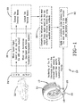
- a tire tread wear estimation system 10 is shown based on spectral analysis of the tire vertical vibration signal. Such a system is useful in advising a vehicle owner on when to change tires and may be used to provide a driver with information on the interrelation between the state of tire tread wear and other factors such as road condition. Tire properties generally change as a function of tire wear. Accordingly, an estimate of tire tread wear level may be used as one input for tire state estimation.
- Tires (a representative one) 12 mounted to a vehicle 22 include ground-engaging tread regions 14 that wear over time.
- the tires 12 enclose a tire cavity 18 by means of a tire innerliner 16.
- a tire pressure monitoring system module (TPMS) 20 may be affixed to the tire innerliner 16.
- the module 20 stores tire ID information from which tire specific construction data may be identified.
- the system 10 employs a tire wear state estimation algorithm uses signals 26 available on a CAN bus (controller area network) 24 of vehicle 22.
- the signals may include wheel speed signals, useful as an input for an ABS (anti-lock braking system) and/or a wheel hub acceleration signal, on vehicles equipped with an active suspension management system.
- mode extractions 28 are made, extracting torsional modes, and from the wheel hub acceleration signal, extracting tire vertical modes.
- An evaluation 30 is then conducted of the tire vertical modes to correlate the influence of the tire wear state (depth level of the tire tread 14) on the tire vertical mode by using spectral analysis methods.
- Application 32 of a correlation model is made between the tire wear state and the tire vertical mode using the tire specific models developed from TPMS-facilitated tire identification information.
- a wheel hop mode exits around 10 Hz (not shown in the graph) as the rim and the belt rotating the experimental tire move up and down together.
- the next vertical mode, the tire vertical mode exists around 80 Hz as illustrated by peak 100; in this vertical belt mode the belt moves up and down but the rim does not move as much.
- the wheel hop vertical mode depends mainly on suspension spring properties supporting the test wheel and tire and the overall tire stiffness.
- Inflation pressure affects the vertical stiffness of a tire; tread depth affects belt mass (m); vertical load affects impact force; rotational velocity affects impact force and stiffness; and road roughness affects input excitation.
- the graphs 34, 36, 38, 40 shown respectively in FIGS. 3A, 3B , 4A , 4B show experimentally how different operating conditions influence the resonance frequencies of the tire. Cleated wheel tests were performed on a fixed spindle machine. Cleat inputs are known to introduce torsional and vertical excitations in a tire while the spindle machine controls tire load and rolling speed. The road roughness effects are captured by using cleats of different sizes and the inflation pressure was manually changed prior to each test. The wear dependencies were captured by using tires with different levels of non-skid depth.
- a hub force measurement was made on a tire using the cleated wheel test and from the hub force measurement, tire vibration modes were determined by means of an FFT (Fast Fourier Transform) analysis.
- FFT Fast Fourier Transform
- the FFT analysis conventionally used as a signal processing tool, yields tire vibration modes including the vertical mode represented in the subject graphs.
- FFT is an algorithmic tool which operates by decomposing an N point time domain signal into N time domain signals each composed of a single point. The second step is to calculate the N frequency spectra corresponding to these N time domain signals. Lastly, the N spectra are synthesized into a single frequency spectrum.
- the vertical modes at the tested inflation pressure were found to be, respectively 80, 84, and 85 Hz.
- the results indicate that changes in signal amplitude and its spectral content are moderately high as a result of tire inflation variance.
- FIG. 4B shows test results of the tire under a range of loads on a wheel having cleats of 5 mm.
- the graph 40 summarizes speed dependency and shows that a change in the tire rolling speed influences the signal amplitude but changes in the signal spectral content are reasonably low. A more significant change in the spectral content at higher speeds can occur where the centrifugal stiffening effect on the tire becomes a dominant factor.
- FIG. 6 the dependency of the vertical mode frequency FFT-Fz is graphically shown in graph 46 for a tire at full tread, half tread and no tread.
- tire wear state dependencies create the highest vertical mode divergencies.
- the relatively high tire wear state dependencies provide the verification and basis for the development of a tire wear state estimation algorithm pursuant to the invention.
- FIG. 8 the goodness of fit of the tread wear estimation model is shown by graph 54.
- a polynomial model (second-order in pressure and first-order in tread depth) were found to give a good fit.
- the tire wear state is derived from a model 58 capturing the dependencies between the tire wear state, inflation pressure and the tire vertical mode frequency.
- Inflation pressure of the tire 12 and tire ID information 56 is obtained from the TPMS module 20 mounted to the tire.
- the Model Coefficients are tire-construction specific and are ascertained by the tire identification obtained from TPMS stored data.
- a recursive least squares (RLS) estimate of the tire wear state can be made using the tire inflation pressure, tire ID (to use the correct model coefficients) and the tire vertical mode frequency information.
- the sensors and data stored within TPMS module 20 is used to obtain pressure and tire ID information.
- the measurement of tire vertical mode on the vehicle is derived from either a wheel-mounted accelerometer or a tire crown-mounted accelerometer by using a spectral analysis methods.
- the RLS Estimation Algorithm (with forgetting factor) provides a method to iteratively update the unknown parameter at each sampling time to minimize the sum of the squares of the modeling error using the past data contained within the regression vector.
- the following is the model capturing the dependency between the tire wear state, inflation pressure and the tire vertical mode frequency:
- Tire Vertical Mode Frequency p00 + p10*pressure + p01*tread depth + p20*pressure ⁇ 2 + p11*pressure*tread depth
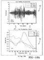
- FIGS. 10A through C estimation performance using the recursive least squares (RLS) estimation algorithm (with forgetting factor) is shown graphically by tire vertical mode [Hz] and corresponding tread depth (estimation) graphs.
- FIG. 10A graphs 60, 62 are for a new tire;
- FIG. 10B graphs 64, 66 for a half-worn tire;
- FIG. 10C graphs 68, 70 for a fully worn tire.
- the subject method for tire wear estimation may utilize either an on-vehicle measurement of the tire vertical mode or an in-tire measurement of the tire vertical mode, or both for the purpose of cross-validation.
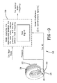
- FIG. 14 shows in block level diagram the on-vehicle algorithm implementation using vehicle measurement of the tire vertical mode.
- the vehicle 22 provides by CAN bus vehicle speed, load and throttle position used to detect the tire free rolling condition to a tire wear state estimation model 80, represented graphically in FIG. 13 .
- a tire wear state estimation model 80 also obtained from the vehicle is the hub vertical acceleration signal from which through spectral analysis the tire vertical mode frequency is obtained.
- the tire vertical mode frequency is likewise input into the tire wear state estimation model 80.
- inflation pressure and tire ID data is obtained from the TPMS module 20 and input into the tire wear state estimation model.
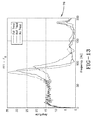
- FIG. 13 shows the model for full tread, half-tread, and no tread results in graph 76.
- a second approach to measurement of the tire vertical mode envisions an in-tire measurement.
- An accelerometer is mounted in the crown region (tread 14) of the tire 12.
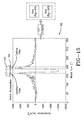
- a vertical acceleration signal is obtained as represented by graph 82 of FIG. 15 , the leading and trailing edges of which being identified.
- the tire vertical mode is extracted using FFT analysis technique common in the field of signal processing. Load dependence and pressure dependence studies in the frequency domain are shown graphically in FIGS. 16A and 16B by graphs 84, 86, respectively.
- FIG. 17 on-vehicle algorithm implementation system for in-tire measurement of the tire vertical mode is shown in block diagram.
- the vehicle 22 provides by CAN bus 24 the vehicle speed, load and throttle position as input into the tire wear state estimation model shown graphically in FIG. 13 .
- the TPMS (including an accelerometer) module 20 provides inflation pressure, tire ID data and a radial acceleration signal from a crown mounted accelerometer. From a spectral analysis of the radial acceleration signal, as explained above, the tire vertical mode frequency is obtained and input to the tire wear state estimation model ( FIG. 13 ). An estimated tire wear state can thus be obtained.
- FIG. 18A shows graphs 92, 94 depicting raw hub vertical acceleration signals for new, half worn and fully worn tires and the hub acceleration signal for the three tire conditions.
- FIG. 18B shows the detrended (corrected) hub acceleration signal 96 for the three tire conditions and peak fit hub acceleration signals 98 for the three tire conditions derived therefrom.
- the peak fit approach indicates a close fit between the graphs in all tire conditions.
- the subject tread wear estimation system utilizes a novel algorithm to estimate the tire wear state.
- Tire wear state is recursively estimated by using a RLS algorithm formulated based on a polynomial model which captures the dependencies between the tire wear state, inflation pressure and the tire vertical mode frequency.
- the model inputs for the RLS algorithm include: tire inflation pressure, tire ID (required for using the correct tire specific model coefficients) and the tire vertical mode frequency.
- the tire inflation pressure and tire ID information is available from a tire attached TPMS module.
- Information about the tire vertical mode frequency can be obtained by using one of the following methods:
Abstract
Description
- The invention relates generally to tire monitoring systems for collecting measured tire parameter data during vehicle operation and, more particularly, to a system and method for estimating tire wear state based upon such measurements.
- Vehicle-mounted tires may be monitored by tire pressure monitoring systems (TPMS) which measure tire parameters such as pressure and temperature during vehicle operation. Data from TPMS tire-equipped systems is used to ascertain the status of a tire based on measured tire parameters and alert the driver of conditions, such as low tire pressure or leakage, which may require remedial maintenance. Sensors within each tire are either installed at a pre-cure stage of tire manufacture or in a post-cure assembly to the tire.
- Other factors such as tire wear state are important considerations for vehicle operation and safety. It is accordingly further desirable to measure tire wear state and communicate wear state to vehicle systems such as braking and stability control systems in conjunction with the measured tire parameters of pressure and temperature.
- The invention relates to a system in accordance with
claim 1 and to a method in accordance withclaim 7. - Dependent claims refer to preferred embodiments of the invention.
- According to one preferred aspect of the invention, a tire wear state estimation system includes a tire pressure measuring device affixed to a vehicle tire for measuring tire inflation pressure and generating tire inflation pressure data; tire vertical mode measuring means for measuring tire vertical mode frequency and generating tire vertical mode frequency data; and tire identification means for generating tire-specific frequency mode coefficients using tire-specific identification data. A tire wear estimation is made based upon the tire inflation pressure data, the vertical mode frequency data, and the tire-specific frequency mode coefficients.
- In another preferred aspect, the tire-mounted pressure measuring device is operative to measure a tire cavity pressure and transmit the tire inflation pressure data from the tire cavity pressure measurement and the tire-specific identification data is stored within and accessible from the tire-mounted pressure measuring device.
- Pursuant to another preferred aspect of the invention, the tire-specific frequency mode coefficients are generated by either using on-vehicle or in-tire measurement of a tire vertical mode frequency, effected respectively from either a wheel-mounted accelerometer or a tire crown-mounted accelerometer.
- The tire wear state estimation system, in another preferred aspect, uses a correlation model between the tire wear state and the tire vertical mode frequency wherein the correlation model employs a recursive least squares algorithm based on a polynomial model capturing a dependency between a wear state of the tire, the tire inflation pressure data, and the tire vertical mode frequency.
- "ANN" or "Artificial Neural Network" is an adaptive tool for non-linear statistical data modeling that changes its structure based on external or internal information that flows through a network during a learning phase. ANN neural networks are non-linear statistical data modeling tools used to model complex relationships between inputs and outputs or to find patterns in data.
- "Axial" and "axially" means lines or directions that are parallel to the axis of rotation of the tire.
- "CAN bus" is an abbreviation for controller area network.
- "Circumferential" means lines or directions extending along the perimeter of the surface of the annular tread perpendicular to the axial direction.
- "Footprint" means the contact patch or area of contact created by the tire tread with a flat surface as the tire rotates or rolls.
- "Inboard side" means the side of the tire nearest the vehicle when the tire is mounted on a wheel and the wheel is mounted on the vehicle.
- "Kalman Filter" is a set of mathematical equations that implement a predictor-corrector type estimator that is optimal in the sense that it minimizes the estimated error covariance when some presumed conditions are met.
- "Lateral" means an axial direction.
- "Lateral edges" means a line tangent to the axially outermost tread contact patch or footprint as measured under normal load and tire inflation, the lines being parallel to the equatorial centerplane.
- "Luenberger Observer" is a state observer or estimation model. A "state observer" is a system that provide an estimate of the internal state of a given real system, from measurements of the input and output of the real system. It is typically computer-implemented, and provides the basis of many practical applications.
- "MSE" is an abbreviation for Mean square error, the error between and a measured signal and an estimated signal which the Kalman Filter minimizes.
- "Net contact area" means the total area of ground contacting tread elements between the lateral edges around the entire circumference of the tread divided by the gross area of the entire tread between the lateral edges.
- "Outboard side" means the side of the tire farthest away from the vehicle when the tire is mounted on a wheel and the wheel is mounted on the vehicle.
- "Piezoelectric Film Sensor" a device in the form of a film body that uses the piezoelectric effect actuated by a bending of the film body to measure pressure, acceleration, strain or force by converting them to an electrical charge.
- "PSD" is Power Spectral Density (a technical name synonymous with FFT (Fast Fourier Transform).
- "Radial" and "radially" means directions radially toward or away from the axis of rotation of the tire.
- The invention will be described by way of example and with reference to the accompanying drawings in which:
-
FIG. 1 is a tread wear state estimation system schematic diagram. -
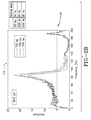
FIG. 2A is a frequency graph showing an amplitude vs. frequency comparison of the vertical mode at three loading levels and at a tire inflation pressure of 32 psi (1 psi = 6894.8 Pascal). -
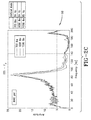
FIG. 2B is a frequency graph showing amplitude vs. frequency comparison of the vertical mode of a tire inflated to 36 psi (1 psi = 6894.8 Pascal) at three loading levels. -
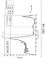
FIG. 2C is a frequency vs. amplitude graph showing the vertical mode of a tire inflated to 40 psi (1 psi = 6894.8 Pascal) at the referenced three loading levels. -
FIG. 3A is a frequency vs. amplitude graph showing the vertical mode at a tire loading of 700 pounds (1 pound = 0.4536 kg) on a tire comparing two tire cleat sizes. -
FIG. 3B is a frequency vs. amplitude graph showing the vertical mode at a tire loading of 1300 pounds (1 pound = 0.4536 kg) on a tire comparing two tire cleat sizes. -
FIG. 4A is a summary frequency vs. vertical mode amplitude graph for a tire cleat of 3mm size at three different tire loading levels. -
FIG. 4B is a summary frequency vs. vertical mode amplitude graph for a tire cleat of 5mm size at three different tire loading levels. -
FIG 5 is a set of graphs showing frequency vs. vertical mode amplitude for a tire inflated to 40 psi and 32 psi (1 psi = 6894.8 Pascal), comparing the experimental results attained at four different vehicle speeds. -
FIG. 6 is a comparison graph of vertical mode frequency vs. amplitude for full, half and no tread conditions and showing sensitivity of the vertical mode in tabular form. -
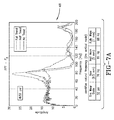
FIG. 7A is a graph similar toFIG. 6 at a tire inflation of 32 psi (1 psi = 6894.8 Pascal) and showing in table form the identified tire vertical mode frequency for the three tire wear states. -
FIG. 7B is a graph and table similar toFIG. 7A for a tire inflated to 36 psi (1 psi = 6894.8 Pascal). -
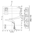
FIG. 7C is a graph and table similar toFIG. 7A for a tire inflated to 40 psi (1 psi = 6894.8 Pascal). -
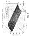
FIG. 8 is a three dimensional graph showing the "goodness" of model fit, showing tire vertical mode frequency vs. tread depth and pressure. -
FIG. 9 is a block diagram of the tire wear state system. -
FIG. 10A are graphs showing estimator performance for a new tire at a speed of 60 mph (1 mph = 1.609 km/h) and inflation pressure of 36 psi (1 psi = 6894.8 Pascal). -
FIG. 10B are graphs showing estimator performance for a half-worn tire. -
FIG. 10C are the graphs showing estimator performance for a fully worn tire. -
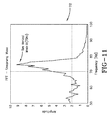
FIG. 11 is a graph showing successful extraction of the tire vertical mode from the vertical accelerations signal of a hub mounted accelerometer. -
FIG. 12 is a surface effect graph of FFT for Unsprung Mass condition on concrete at 40 mph (1 mph = 1.609 km/h). -
FIG. 13 is a comparative graph of FFT-Fz showing amplitude vs. frequency for full tread, half tread and no tread conditions. -
FIG. 14 is a block level diagram of the tire wear system using On Vehicle Algorithm Implementation and Vehicle Measurement of the Tire Vertical Mode. -
FIG. 15 is a graph showing a second approach to tire vertical mode determination, using the vertical acceleration signal of a crown mounted accelerometer. -
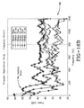
FIG. 16A is a graph showing the results of a load dependence study in the frequency domain showing the tire vertical mode for three load levels in power [db] vs. frequency. -
FIG. 16B is a graph showing the results of a pressure dependence Study in the Frequency Domain for a tire travelling at 30, 45, 65 mph (1 mph = 1.609 km/h) and at inflation levels of 32 and 35 psi (1 psi = 6894.8 Pascal). -
FIG. 17 is a block level diagram of On Vehicle Algorithm Implementation using In-tire Measurement of the Tire Vehicle Mode. -
FIG. 18A shows graphs indicating the raw signal of hub vertical acceleration for a new, half worn and fully worn tire and the FFT Hub Acceleration signal in the frequency domain. -
FIG. 18B are graphs showing the detrended FFT Hub Acceleration Signal for a new, half worn and fully worn tire and the peak fit graph of the acceleration signal graph. - Referring to
FIG. 1 , a tire tread wearestimation system 10 is shown based on spectral analysis of the tire vertical vibration signal. Such a system is useful in advising a vehicle owner on when to change tires and may be used to provide a driver with information on the interrelation between the state of tire tread wear and other factors such as road condition. Tire properties generally change as a function of tire wear. Accordingly, an estimate of tire tread wear level may be used as one input for tire state estimation. - Tires (a representative one) 12 mounted to a
vehicle 22 include ground-engagingtread regions 14 that wear over time. Thetires 12 enclose atire cavity 18 by means of atire innerliner 16. A tire pressure monitoring system module (TPMS) 20 may be affixed to thetire innerliner 16. Themodule 20 stores tire ID information from which tire specific construction data may be identified. - The
system 10 employs a tire wear state estimation algorithm usessignals 26 available on a CAN bus (controller area network) 24 ofvehicle 22. The signals may include wheel speed signals, useful as an input for an ABS (anti-lock braking system) and/or a wheel hub acceleration signal, on vehicles equipped with an active suspension management system. From the wheel speed signal,mode extractions 28 are made, extracting torsional modes, and from the wheel hub acceleration signal, extracting tire vertical modes. Anevaluation 30 is then conducted of the tire vertical modes to correlate the influence of the tire wear state (depth level of the tire tread 14) on the tire vertical mode by using spectral analysis methods.Application 32 of a correlation model is made between the tire wear state and the tire vertical mode using the tire specific models developed from TPMS-facilitated tire identification information. - With reference to
FIG. 2A , the tire vertical vibration mode FFT-FZ of a vibrating tire is examined. Experimental results are illustrated graphically ingraph 28 of amplitude vs. frequency (Hz) of the vibrating tire having an inflation of 32 psi (1 psi = 6894.8 Pascal) for three loadings: 700, 1000 and 1,300 pounds (1 pound = 0.4536 kg). A wheel hop mode exits around 10 Hz (not shown in the graph) as the rim and the belt rotating the experimental tire move up and down together. The next vertical mode, the tire vertical mode, exists around 80 Hz as illustrated bypeak 100; in this vertical belt mode the belt moves up and down but the rim does not move as much. The tire vertical tire vertical mode detected experimentally at the three loadings is shown in the associated table ofFIG. 2A ; for 700 pounds (1 pound = 0.4536 kg) a vertical mode at 80 Hz; for 1000 pounds (1 pound = 0.4536 kg) a vertical mode at 84 Hz, and for 1300 pounds (1 pound = 0.4536 kg) a vertical load at 85 Hz. The wheel hop vertical mode depends mainly on suspension spring properties supporting the test wheel and tire and the overall tire stiffness. -
FIGS. 2B and2C respectively show for comparison purposes a testing of a rotating suspended tire and wheel assembly bygraphs 
where "k" is the tire carcass, inflation pressure dependent and m is the mass of the tire belt and tread mass. The dependence of tire wear (reduction in mass of the tread) and tire vertical mode of a rotating tire forms the basis for a correlation model between the tire wear state and the tire vertical mode frequency. - Apart from tire inflation pressure and tread mass, other factors were determined which influence tire vertical mode frequency. Those other factors include tire load, rolling speed and road roughness level (smooth versus rough or very rough). Inflation pressure affects the vertical stiffness of a tire; tread depth affects belt mass (m); vertical load affects impact force; rotational velocity affects impact force and stiffness; and road roughness affects input excitation. The
graphs FIGS. 3A, 3B ,4A ,4B show experimentally how different operating conditions influence the resonance frequencies of the tire. Cleated wheel tests were performed on a fixed spindle machine. Cleat inputs are known to introduce torsional and vertical excitations in a tire while the spindle machine controls tire load and rolling speed. The road roughness effects are captured by using cleats of different sizes and the inflation pressure was manually changed prior to each test. The wear dependencies were captured by using tires with different levels of non-skid depth. - A hub force measurement was made on a tire using the cleated wheel test and from the hub force measurement, tire vibration modes were determined by means of an FFT (Fast Fourier Transform) analysis. The FFT analysis, conventionally used as a signal processing tool, yields tire vibration modes including the vertical mode represented in the subject graphs. As used herein, FFT is an algorithmic tool which operates by decomposing an N point time domain signal into N time domain signals each composed of a single point. The second step is to calculate the N frequency spectra corresponding to these N time domain signals. Lastly, the N spectra are synthesized into a single frequency spectrum.
- In
FIG. 3A , cleats of 3mm and 5mm were used and the vertical mode FFT-Fz determined for a load of 700 pounds (1 pound = 0.4536 kg). InFIG. 3B , for the same two cleat sizes, thegraph 36 at a tire loading of 1300 pounds (1 pound = 0.4536 kg) is shown. As reflected in thegraphs - Tire inflation dependencies were also tested as reflected in test results of
FIGS. 4A and4B .FIG. 4A shows the test results 38 for a tire on a cleated wheel with cleat size of 3 mm for inflation pressures of 32, 36, and 40 psi (1 psi = 6894.8 Pascal). The vertical modes at the tested inflation pressure were found to be, respectively 80, 84, and 85 Hz. The results indicate that changes in signal amplitude and its spectral content are moderately high as a result of tire inflation variance. -
FIG. 4B shows test results of the tire under a range of loads on a wheel having cleats of 5 mm. Thegraph 40 summarizes speed dependency and shows that a change in the tire rolling speed influences the signal amplitude but changes in the signal spectral content are reasonably low. A more significant change in the spectral content at higher speeds can occur where the centrifugal stiffening effect on the tire becomes a dominant factor. -
FIG. 5 summarizes graphically withgraphs - In
FIG. 6 , the dependency of the vertical mode frequency FFT-Fz is graphically shown ingraph 46 for a tire at full tread, half tread and no tread. As seen by the differing vertical mode computations in the table, tire wear state dependencies create the highest vertical mode divergencies. The relatively high tire wear state dependencies provide the verification and basis for the development of a tire wear state estimation algorithm pursuant to the invention. -
Graphs FIGS. 7A through C , respectively, show test results indicative of tread wear state dependencies for a test tire at respective inflation levels of 32, 36, and 40 psi (1 psi = 6894.8 Pascal). The graphs and their tabular summaries indicate that the trends (tread wear dependencies) are consistent across all inflation pressure conditions. - In
FIG. 8 , the goodness of fit of the tread wear estimation model is shown bygraph 54. The model fit is compared against experimental data and with the fit yielding a correlation coefficient (r) =0.988. Validation of the model is thus indicated. A polynomial model (second-order in pressure and first-order in tread depth) were found to give a good fit. - Referring to
FIG. 9 , a tire-based flow chart model implementation is shown. The tire wear state is derived from amodel 58 capturing the dependencies between the tire wear state, inflation pressure and the tire vertical mode frequency. Inflation pressure of thetire 12 and tire ID information 56 is obtained from theTPMS module 20 mounted to the tire. The Model Coefficients are tire-construction specific and are ascertained by the tire identification obtained from TPMS stored data. For a given tire construction, a recursive least squares (RLS) estimate of the tire wear state can be made using the tire inflation pressure, tire ID (to use the correct model coefficients) and the tire vertical mode frequency information. The sensors and data stored withinTPMS module 20 is used to obtain pressure and tire ID information. The measurement of tire vertical mode on the vehicle is derived from either a wheel-mounted accelerometer or a tire crown-mounted accelerometer by using a spectral analysis methods. - The RLS Estimation Algorithm (with forgetting factor) provides a method to iteratively update the unknown parameter at each sampling time to minimize the sum of the squares of the modeling error using the past data contained within the regression vector. The following is the model capturing the dependency between the tire wear state, inflation pressure and the tire vertical mode frequency:
- Tire Vertical Mode Frequency = p00 + p10*pressure + p01*tread depth + p20*pressure^2 + p11*pressure*tread depth
- Model Coefficients (with 95 percent confidence bounds):
- p00
- = -35.94 (-171.6, 99.72)
- p10
- = 6.586 (-0.9712, 14.14)
- p01
- = -2.31 (-5.37, 0.7512)
- p20
- = -0.08333 (-0.1881, 0.02144)
- p11
- = 0.01786 (-0.06682, 0.1025)
- The above equation can be rewritten into a standard parameter identification form as follows:

- Where:


θ = Tread depth (unknown - to be estimated) - The procedure for solving the RLS problem is as follows:
- Step 0: Initialize the unknown parameter θ(0) and the covariance matrix P(0); set the forgetting factor λ.
- Step 1: Measure the system output y(t) and compute the regression vector ϕ(t).
- Step 2: Calculate the identification error e(t):

- Step 3: Calculate the gain k(t):

- Step 4: Calculate the covariance matrix:

- Step 5: Update the unknown parameter:

- Step 6:
Repeat Steps 1 through 5 for each time step. - Referring to
FIGS. 10A through C , estimation performance using the recursive least squares (RLS) estimation algorithm (with forgetting factor) is shown graphically by tire vertical mode [Hz] and corresponding tread depth (estimation) graphs.FIG. 10A graphs FIG. 10B graphs FIG. 10C graphs - The subject method for tire wear estimation may utilize either an on-vehicle measurement of the tire vertical mode or an in-tire measurement of the tire vertical mode, or both for the purpose of cross-validation. For on-vehicle measurement, the vertical mode is extracted from the vertical acceleration signal of a hub-mounted accelerometer. Hub-mounted accelerometers are commercially available and are used as part of vehicle suspension management systems. From tests conducted on various surfaces, it was found that the tire vertical mode was successfully detected under all the test conditions. For example,
graph 74 ofFIG. 12 shows the vertical mode from an accelerometer measurement conducted on a tire travelling on concrete at 40 mph (1 mph = 1.609 km/h). The amplitude of 9.208 and frequency [Hz] 74.38 were measured. Similar testing was conducted on an impact strip at a travel speed of 25 mph (1 mph = 1.609 km/h) and a pothole at 10 mph (1 mph = 1.609 km/h). The test results all verified the extracting vertical mode from a hub-mounted accelerometer for the purpose of tread wear estimation pursuant to the subject methodology. -
FIG. 14 shows in block level diagram the on-vehicle algorithm implementation using vehicle measurement of the tire vertical mode. Thevehicle 22 provides by CAN bus vehicle speed, load and throttle position used to detect the tire free rolling condition to a tire wearstate estimation model 80, represented graphically inFIG. 13 . Also obtained from the vehicle is the hub vertical acceleration signal from which through spectral analysis the tire vertical mode frequency is obtained. The tire vertical mode frequency is likewise input into the tire wearstate estimation model 80. From thetire 12, inflation pressure and tire ID data is obtained from theTPMS module 20 and input into the tire wear state estimation model.FIG. 13 shows the model for full tread, half-tread, and no tread results ingraph 76. - A second approach to measurement of the tire vertical mode envisions an in-tire measurement. An accelerometer is mounted in the crown region (tread 14) of the
tire 12. From the sensor, a vertical acceleration signal is obtained as represented bygraph 82 ofFIG. 15 , the leading and trailing edges of which being identified. From the vertical acceleration signal, the tire vertical mode is extracted using FFT analysis technique common in the field of signal processing. Load dependence and pressure dependence studies in the frequency domain are shown graphically inFIGS. 16A and16B bygraphs FIG. 16A , the tire vertical mode is identified for loading of 1300, 1500 and 1800 pounds (1 pound = 0.4536 kg). InFIG. 16B , pressure dependence results summarized ingraph 86 are form speeds of 30, 45 and 65 mph (1 mph = 1.609 km/h) and inflation pressures of 32 and 35 psi (1 psi = 6894.8 Pascal). The results verify the efficacy of using a tire-based accelerometer sensor to identify the tire vertical mode. - In
FIG. 17 , on-vehicle algorithm implementation system for in-tire measurement of the tire vertical mode is shown in block diagram. Thevehicle 22 provides byCAN bus 24 the vehicle speed, load and throttle position as input into the tire wear state estimation model shown graphically inFIG. 13 . From thetire 12, the TPMS (including an accelerometer)module 20 provides inflation pressure, tire ID data and a radial acceleration signal from a crown mounted accelerometer. From a spectral analysis of the radial acceleration signal, as explained above, the tire vertical mode frequency is obtained and input to the tire wear state estimation model (FIG. 13 ). An estimated tire wear state can thus be obtained. -
FIG. 18A showsgraphs FIG. 18B shows the detrended (corrected)hub acceleration signal 96 for the three tire conditions and peak fit hub acceleration signals 98 for the three tire conditions derived therefrom. The peak fit approach indicates a close fit between the graphs in all tire conditions. - From the foregoing, it will be appreciated the subject tread wear estimation system utilizes a novel algorithm to estimate the tire wear state. Tire wear state is recursively estimated by using a RLS algorithm formulated based on a polynomial model which captures the dependencies between the tire wear state, inflation pressure and the tire vertical mode frequency. The model inputs for the RLS algorithm include: tire inflation pressure, tire ID (required for using the correct tire specific model coefficients) and the tire vertical mode frequency. The tire inflation pressure and tire ID information is available from a tire attached TPMS module. Information about the tire vertical mode frequency can be obtained by using one of the following methods:
- Approach 1: Using on-vehicle measurement of the tire vertical mode, i.e. extract the tire vertical mode frequency from the vertical acceleration signal of a hub (wheel) mounted accelerometer.
- Approach 2: In-tire measure of the tire vertical mode, i.e. extract the tire vertical mode frequency from the vertical acceleration signal of a crown mounted accelerometer.
- Both approaches may be employed for cross-validation of results. The application of the real-time RLS algorithm in achieving the desired tread wear estimation and accurate estimation results were experimentally validated.
Claims (12)
- A tire wear state estimation system comprising:at least one tire for supporting a vehicle;tire pressure measuring means affixed to the at least one tire for measuring tire inflation pressure and for generating tire inflation pressure data;tire vertical mode measuring means for measuring tire vertical mode frequency and for generating tire vertical mode frequency data;tire identification means for generating tire-specific frequency mode coefficients using tire-specific identification data; andtire wear estimation means for calculating an estimation of a tire wear state based upon the tire inflation pressure data, the vertical mode frequency data, and the tire-specific frequency mode coefficients.
- The tire wear state estimation system of claim 1, wherein the tire pressure measuring means comprises a tire-mounted pressure measuring device operative to measure a tire cavity pressure and to transmit the tire inflation pressure data from the tire cavity pressure measurement.
- The tire wear state estimation system of claim 1 or 2, wherein the tire identification means comprises tire-specific identification data stored within and accessible from the tire-mounted pressure measuring device.
- The tire wear state estimation system of at least one of the previous claims comprising a wheel-mounted accelerometer or a tire crown-mounted accelerometer for measuring the tire vertical mode frequency from said wheel-mounted accelerometer or said tire crown-mounted accelerometer.
- The tire wear state estimation system of at least one of the previous claims, wherein the tire wear estimation means comprises a correlation model between the tire wear state and the tire vertical mode frequency.
- The tire wear state estimation system in accordance with at least one of the previous claims comprising:a tire-mounted pressure measuring device affixed to the at least one tire operative to measure a tire cavity pressure and to transmit tire inflation pressure data from the tire cavity pressure measurement;tire-specific identification data stored within and accessible from the tire-mounted pressure measuring device; andsaid tire identification means for generating tire-specific frequency mode coefficients using the tire-specific identification data and on-vehicle or in-tire measurement of a tire vertical mode frequency.
- A method of tire wear state estimation, the method comprising:affixing a tire pressure measuring device to a vehicle-supporting tire;measuring a tire cavity inflation pressure using the pressure measuring device and generating tire inflation pressure data;measuring tire vertical mode frequency and generating tire vertical mode frequency data;generating tire-specific frequency mode coefficients using tire-specific identification data; andcalculating an estimation of a tire wear state based upon the tire inflation pressure data, the vertical mode frequency data, and the tire-specific frequency mode coefficients.
- The method of claim 7, further comprising generating the tire-specific frequency mode coefficients using on-vehicle or in-tire measurement of a tire vertical mode frequency.
- The method of claim 7 or 8, further comprising measuring the tire vertical mode frequency from a wheel-mounted accelerometer or a tire crown-mounted accelerometer.
- The method of at least one of the previous claims 7 to 9 wherein calculating an estimation of the tire wear state comprises employing a correlation model between the tire wear state and the tire vertical mode frequency.
- The method of claim 10, further comprising configuring the correlation model to comprise a recursive least squares algorithm based on a polynomial model capturing a dependency between the tire wear state, the tire inflation pressure data, and the tire vertical mode frequency.
- The tire wear state estimation system of at least one of the previous claims, wherein the tire-specific frequency mode coefficients are generated by the tire identification means using on-vehicle or in-tire measurement of a tire vertical mode frequency.
Applications Claiming Priority (1)
| Application Number | Priority Date | Filing Date | Title |
|---|---|---|---|
| US13/917,691 US9050864B2 (en) | 2013-06-14 | 2013-06-14 | Tire wear state estimation system and method |
Publications (2)
| Publication Number | Publication Date |
|---|---|
| EP2813378A1 true EP2813378A1 (en) | 2014-12-17 |
| EP2813378B1 EP2813378B1 (en) | 2016-12-21 |
Family
ID=50942049
Family Applications (1)
| Application Number | Title | Priority Date | Filing Date |
|---|---|---|---|
| EP14171347.9A Active EP2813378B1 (en) | 2013-06-14 | 2014-06-05 | Tire wear state estimation system and method |
Country Status (2)
| Country | Link |
|---|---|
| US (1) | US9050864B2 (en) |
| EP (1) | EP2813378B1 (en) |
Cited By (12)
| Publication number | Priority date | Publication date | Assignee | Title |
|---|---|---|---|---|
| EP3088219A1 (en) * | 2015-04-29 | 2016-11-02 | The Goodyear Tire & Rubber Company | Tire sensor-based mileage tracking system and method |
| GB2539270A (en) * | 2015-06-12 | 2016-12-14 | Jaguar Land Rover Ltd | Control system, vehicle and method |
| GB2539272A (en) * | 2015-06-12 | 2016-12-14 | Jaguar Land Rover Ltd | Control system, vehicle and method |
| EP3210799A1 (en) * | 2016-02-26 | 2017-08-30 | The Goodyear Tire & Rubber Company | Tire wear estimation system and method |
| EP3330106A1 (en) * | 2016-12-05 | 2018-06-06 | The Goodyear Tire & Rubber Company | Indirect tire pressure and wear state estimation system and method |
| CN108146161A (en) * | 2016-12-05 | 2018-06-12 | 固特异轮胎和橡胶公司 | Wheel Imbalance Detection System And Method |
| EP3378679A1 (en) * | 2017-03-23 | 2018-09-26 | The Goodyear Tire & Rubber Company | Model based tire wear estimation system and method |
| IT201800007884A1 (en) * | 2018-08-06 | 2020-02-06 | Bridgestone Europe Nv Sa | SYSTEM AND METHOD FOR MONITORING THE CONSUMPTION OF TREAD |
| US10603962B2 (en) | 2017-06-29 | 2020-03-31 | The Goodyear Tire & Rubber Company | Tire wear state estimation system and method |
| EP3666554A1 (en) * | 2018-12-11 | 2020-06-17 | The Goodyear Tire & Rubber Company | Tire wear state estimation system and method |
| WO2022144939A1 (en) * | 2020-12-30 | 2022-07-07 | Pirelli Tyre S.P.A. | Method for monitoring a status of a tyre |
| US11498371B2 (en) | 2018-12-12 | 2022-11-15 | The Goodyear Tire & Rubber Company | Tire data information system |
Families Citing this family (34)
| Publication number | Priority date | Publication date | Assignee | Title |
|---|---|---|---|---|
| US9259976B2 (en) * | 2013-08-12 | 2016-02-16 | The Goodyear Tire & Rubber Company | Torsional mode tire wear state estimation system and method |
| US9290069B2 (en) * | 2014-02-03 | 2016-03-22 | The Goodyear Tire & Rubber Company | Tire innerliner-based parameter estimation system and method |
| US9442045B2 (en) | 2014-04-03 | 2016-09-13 | The Goodyear Tire & Rubber Company | Model-based longitudinal stiffness estimation system and method |
| US9751533B2 (en) | 2014-04-03 | 2017-09-05 | The Goodyear Tire & Rubber Company | Road surface friction and surface type estimation system and method |
| US9434409B2 (en) * | 2014-04-03 | 2016-09-06 | The Goodyear Tire & Rubber Company | Tire lateral force model with temperature adaptation and method |
| US9963132B2 (en) | 2014-11-10 | 2018-05-08 | The Goodyear Tire & Rubber Company | Tire sensor-based vehicle control system optimization and method |
| US10245906B2 (en) | 2014-11-11 | 2019-04-02 | The Goodyear Tire & Rubber Company | Tire wear compensated load estimation system and method |
| US9739689B2 (en) | 2014-11-21 | 2017-08-22 | The Goodyear Tire & Rubber Company | Tire cornering stiffness estimation system and method |
| US20160161373A1 (en) | 2014-12-03 | 2016-06-09 | The Goodyear Tire & Rubber Company | Tire lift-off propensity predictive system and method |
| US9963146B2 (en) | 2014-12-03 | 2018-05-08 | The Goodyear Tire & Rubber Company | Tire lift-off propensity predictive system and method |
| US9650053B2 (en) | 2014-12-03 | 2017-05-16 | The Goodyear Tire & Rubber Company | Slip ratio point optimization system and method for vehicle control |
| GB2533658A (en) * | 2014-12-22 | 2016-06-29 | Continental Automotive Gmbh | Method and system for determining a wheel load acting on a tire of a vehicle |
| US9821611B2 (en) * | 2015-10-21 | 2017-11-21 | The Goodyear Tire & Rubber Company | Indirect tire wear state estimation system |
| US9878721B2 (en) | 2015-11-11 | 2018-01-30 | The Goodyear Tire & Rubber Company | Tire sensor-based robust mileage tracking system and method |
| JP6682369B2 (en) * | 2016-06-09 | 2020-04-15 | 株式会社ブリヂストン | Tire deterioration condition prediction method |
| CN106198058B (en) * | 2016-08-03 | 2017-04-19 | 东南大学 | Real-time vertical wheel impact force measurement method based on tire pressure monitoring |
| BR112019006959A2 (en) | 2016-10-05 | 2019-07-02 | Solera Holdings Inc | vehicle tire monitoring systems and methods |
| HUE054879T2 (en) * | 2016-12-06 | 2021-10-28 | Pieper Joerg | Method and device for determining the wear of a tire |
| KR102616222B1 (en) * | 2016-12-22 | 2023-12-21 | 에스케이플래닛 주식회사 | Tire abrasion confirmation system, method thereof and computer readable medium having computer program recorded thereon |
| DE102017201519B4 (en) | 2017-01-31 | 2019-04-04 | Ford Global Technologies, Llc | A method and system for determining a wear condition of at least one tire |
| US20180290501A1 (en) * | 2017-04-07 | 2018-10-11 | GM Global Technology Operations LLC | Methods and apparatus for determining remaining life of a tire based on road vibration data and tire tread groove depth |
| CN110239561B (en) * | 2018-03-07 | 2022-08-05 | 奥迪股份公司 | Driving assistance system and method |
| JP2020032990A (en) * | 2018-08-31 | 2020-03-05 | 株式会社ブリヂストン | Tire wear detection method and tire wear detection device |
| JP7180354B2 (en) * | 2018-12-14 | 2022-11-30 | 株式会社Soken | Tire wear detector |
| CN116890577A (en) * | 2019-04-01 | 2023-10-17 | 普利司通美国轮胎运营有限责任公司 | System and method for vehicle tire performance modeling and feedback |
| JP7367404B2 (en) * | 2019-09-04 | 2023-10-24 | 株式会社Soken | tire equipment |
| JP7368181B2 (en) * | 2019-10-29 | 2023-10-24 | Toyo Tire株式会社 | Wear amount estimation system and calculation model generation system |
| CN111121821A (en) * | 2019-12-23 | 2020-05-08 | 广州赛特智能科技有限公司 | Auxiliary inertial navigation system and method thereof |
| CN110962512A (en) * | 2019-12-24 | 2020-04-07 | 深圳供电局有限公司 | Intelligent monitoring system for automobile tire |
| US11458784B2 (en) | 2020-03-25 | 2022-10-04 | Ford Global Technologies, Llc | Methods and apparatus to determine tire tread depth |
| US20220063347A1 (en) | 2020-08-26 | 2022-03-03 | The Goodyear Tire & Rubber Company | Tire wear state estimation system |
| CN112113504B (en) * | 2020-09-18 | 2023-01-31 | 深圳市道通科技股份有限公司 | Brake disc wear diagnosis method and wear diagnosis system |
| KR102541932B1 (en) * | 2020-11-10 | 2023-06-12 | 금호타이어 주식회사 | Tire monitoring system and tire monitoring method using the same |
| EP4015250A1 (en) * | 2020-12-15 | 2022-06-22 | Tata Consultancy Services Limited | System and method for real-time health prediction of tires |
Citations (3)
| Publication number | Priority date | Publication date | Assignee | Title |
|---|---|---|---|---|
| DE19716586C1 (en) * | 1997-04-21 | 1998-08-06 | Continental Ag | Tyre wear measuring method for moving vehicle |
| EP2172760A1 (en) * | 2007-07-11 | 2010-04-07 | Kabushiki Kaisha Bridgestone | Method for detecting abrasion of tire and device for detecting abrasion of tire |
| EP2301769A1 (en) * | 2008-06-25 | 2011-03-30 | Kabushiki Kaisha Bridgestone | Method for estimating tire wear and device for estimating tire wear |
Family Cites Families (11)
| Publication number | Priority date | Publication date | Assignee | Title |
|---|---|---|---|---|
| WO2003031990A1 (en) * | 2001-10-05 | 2003-04-17 | Continental Teves Ag & Co. Ohg | Device for combined detection of axle acceleration and wheel rotational speed, and method for determining pressure |
| EP1457388B1 (en) * | 2001-12-21 | 2015-01-21 | Kabushiki Kaisha Bridgestone | Method and apparatus for estimating road surface state and tire running state |
| DE10218781A1 (en) * | 2002-04-26 | 2003-11-13 | Tuev Automotive Gmbh | Pneumatic tire mountable on a rim, sensor network, revolution measuring unit and vehicle monitoring system |
| CA2543437A1 (en) | 2003-10-24 | 2005-05-12 | Pirelli Pneumatici S.P.A. | Method and system for determining a cornering angle of a tyre during the running of a vehicle |
| JP4680532B2 (en) | 2004-06-02 | 2011-05-11 | 株式会社ブリヂストン | Method and apparatus for estimating dynamic state of tire |
| DE602004012903T2 (en) | 2004-09-29 | 2009-04-09 | Pirelli Tyre S.P.A. | METHOD AND SYSTEM FOR DETERMINING THE SCROLLING ANGLE OF A TIRE WHILE DRIVING A VEHICLE |
| JP5121445B2 (en) | 2005-03-24 | 2013-01-16 | 株式会社ブリヂストン | Estimation method of tire slip angle |
| DE102008056664A1 (en) * | 2007-12-10 | 2009-06-18 | Continental Teves Ag & Co. Ohg | Method for indirect tire pressure monitoring and tire pressure monitoring system |
| IT1393072B1 (en) | 2008-10-24 | 2012-04-11 | Pirelli | METHOD AND SYSTEM FOR REPORTING A CONDITION OF AQUAPLANO OF A TIRE ASSEMBLED ON A VEHICLE |
| DE112009005342B4 (en) | 2009-11-04 | 2019-06-27 | Nira Dynamics Ab | Classification of the road surface |
| DE102010050634A1 (en) * | 2010-11-05 | 2012-05-10 | Wabco Gmbh | A control system for a vehicle control system and method for determining tire conditions of vehicle tires |
-
2013
- 2013-06-14 US US13/917,691 patent/US9050864B2/en active Active
-
2014
- 2014-06-05 EP EP14171347.9A patent/EP2813378B1/en active Active
Patent Citations (3)
| Publication number | Priority date | Publication date | Assignee | Title |
|---|---|---|---|---|
| DE19716586C1 (en) * | 1997-04-21 | 1998-08-06 | Continental Ag | Tyre wear measuring method for moving vehicle |
| EP2172760A1 (en) * | 2007-07-11 | 2010-04-07 | Kabushiki Kaisha Bridgestone | Method for detecting abrasion of tire and device for detecting abrasion of tire |
| EP2301769A1 (en) * | 2008-06-25 | 2011-03-30 | Kabushiki Kaisha Bridgestone | Method for estimating tire wear and device for estimating tire wear |
Cited By (18)
| Publication number | Priority date | Publication date | Assignee | Title |
|---|---|---|---|---|
| EP3088219A1 (en) * | 2015-04-29 | 2016-11-02 | The Goodyear Tire & Rubber Company | Tire sensor-based mileage tracking system and method |
| GB2539270B (en) * | 2015-06-12 | 2019-01-23 | Jaguar Land Rover Ltd | Control system, vehicle and method |
| GB2539270A (en) * | 2015-06-12 | 2016-12-14 | Jaguar Land Rover Ltd | Control system, vehicle and method |
| GB2539272A (en) * | 2015-06-12 | 2016-12-14 | Jaguar Land Rover Ltd | Control system, vehicle and method |
| EP3210799A1 (en) * | 2016-02-26 | 2017-08-30 | The Goodyear Tire & Rubber Company | Tire wear estimation system and method |
| US10406866B2 (en) | 2016-02-26 | 2019-09-10 | The Goodyear Tire & Rubber Company | Tire sensor for a tire monitoring system |
| EP3330106A1 (en) * | 2016-12-05 | 2018-06-06 | The Goodyear Tire & Rubber Company | Indirect tire pressure and wear state estimation system and method |
| CN108146161A (en) * | 2016-12-05 | 2018-06-12 | 固特异轮胎和橡胶公司 | Wheel Imbalance Detection System And Method |
| EP3378679A1 (en) * | 2017-03-23 | 2018-09-26 | The Goodyear Tire & Rubber Company | Model based tire wear estimation system and method |
| EP3378679B1 (en) | 2017-03-23 | 2021-07-28 | The Goodyear Tire & Rubber Company | Model based tire wear estimation system and method |
| US10603962B2 (en) | 2017-06-29 | 2020-03-31 | The Goodyear Tire & Rubber Company | Tire wear state estimation system and method |
| IT201800007884A1 (en) * | 2018-08-06 | 2020-02-06 | Bridgestone Europe Nv Sa | SYSTEM AND METHOD FOR MONITORING THE CONSUMPTION OF TREAD |
| WO2020031022A1 (en) * | 2018-08-06 | 2020-02-13 | Bridgestone Europe Nv/Sa | Tread wear monitoring system and method |
| US11458777B2 (en) | 2018-08-06 | 2022-10-04 | Bridgestone Europe N.V./S.A. | Tread wear monitoring system and method |
| EP3666554A1 (en) * | 2018-12-11 | 2020-06-17 | The Goodyear Tire & Rubber Company | Tire wear state estimation system and method |
| US11644386B2 (en) | 2018-12-11 | 2023-05-09 | The Goodyear Tire & Rubber Company | Tire wear state estimation system and method |
| US11498371B2 (en) | 2018-12-12 | 2022-11-15 | The Goodyear Tire & Rubber Company | Tire data information system |
| WO2022144939A1 (en) * | 2020-12-30 | 2022-07-07 | Pirelli Tyre S.P.A. | Method for monitoring a status of a tyre |
Also Published As
| Publication number | Publication date |
|---|---|
| US20140366618A1 (en) | 2014-12-18 |
| US9050864B2 (en) | 2015-06-09 |
| EP2813378B1 (en) | 2016-12-21 |
Similar Documents
| Publication | Publication Date | Title |
|---|---|---|
| EP2813378B1 (en) | Tire wear state estimation system and method | |
| EP2837510B1 (en) | Torsional mode tire wear state estimation system and method | |
| EP3330106B1 (en) | Indirect tire pressure and wear state estimation system and method | |
| US10603962B2 (en) | Tire wear state estimation system and method | |
| US9874496B2 (en) | Tire suspension fusion system for estimation of tire deflection and tire load | |
| US9821611B2 (en) | Indirect tire wear state estimation system | |
| US8844346B1 (en) | Tire load estimation system using road profile adaptive filtering | |
| EP2705963B1 (en) | Tire sidewall load estimation system and method | |
| US9739689B2 (en) | Tire cornering stiffness estimation system and method | |
| US9610810B1 (en) | Method of tire state estimation through wheel speed signal feature extraction | |
| US20140114558A1 (en) | Vehicle weight and center of gravity estimation system and method | |
| US8494704B2 (en) | Tire pressure classification based tire pressure monitoring | |
| US10048170B2 (en) | Vehicle loading condition detection system and method | |
| US20100013616A1 (en) | Apparatus and method for detecting decrease in tire air pressure and program for detecting decrease in tire air pressure | |
| CN108146161B (en) | Wheel imbalance detection system and method | |
| EP3159189B1 (en) | Indirect tire wear state estimation system and method of tire state estimation through wheel speed signal feature extraction | |
| US9522578B1 (en) | Robust system and method for auto-location of tire-based sensors | |
| JP5464580B2 (en) | Tire resonance frequency decompression sensitivity estimation apparatus and method, and tire resonance frequency decompression sensitivity estimation program |
Legal Events
| Date | Code | Title | Description |
|---|---|---|---|
| 17P | Request for examination filed |
Effective date: 20140605 |
|
| AK | Designated contracting states |
Kind code of ref document: A1 Designated state(s): AL AT BE BG CH CY CZ DE DK EE ES FI FR GB GR HR HU IE IS IT LI LT LU LV MC MK MT NL NO PL PT RO RS SE SI SK SM TR |
|
| AX | Request for extension of the european patent |
Extension state: BA ME |
|
| PUAI | Public reference made under article 153(3) epc to a published international application that has entered the european phase |
Free format text: ORIGINAL CODE: 0009012 |
|
| R17P | Request for examination filed (corrected) |
Effective date: 20150617 |
|
| RBV | Designated contracting states (corrected) |
Designated state(s): AL AT BE BG CH CY CZ DE DK EE ES FI FR GB GR HR HU IE IS IT LI LT LU LV MC MK MT NL NO PL PT RO RS SE SI SK SM TR |
|
| GRAP | Despatch of communication of intention to grant a patent |
Free format text: ORIGINAL CODE: EPIDOSNIGR1 |
|
| INTG | Intention to grant announced |
Effective date: 20160506 |
|
| GRAP | Despatch of communication of intention to grant a patent |
Free format text: ORIGINAL CODE: EPIDOSNIGR1 |
|
| INTG | Intention to grant announced |
Effective date: 20160726 |
|
| GRAS | Grant fee paid |
Free format text: ORIGINAL CODE: EPIDOSNIGR3 |
|
| GRAA | (expected) grant |
Free format text: ORIGINAL CODE: 0009210 |
|
| AK | Designated contracting states |
Kind code of ref document: B1 Designated state(s): AL AT BE BG CH CY CZ DE DK EE ES FI FR GB GR HR HU IE IS IT LI LT LU LV MC MK MT NL NO PL PT RO RS SE SI SK SM TR |
|
| REG | Reference to a national code |
Ref country code: GB Ref legal event code: FG4D |
|
| REG | Reference to a national code |
Ref country code: CH Ref legal event code: EP |
|
| REG | Reference to a national code |
Ref country code: IE Ref legal event code: FG4D |
|
| REG | Reference to a national code |
Ref country code: AT Ref legal event code: REF Ref document number: 855141 Country of ref document: AT Kind code of ref document: T Effective date: 20170115 |
|
| REG | Reference to a national code |
Ref country code: DE Ref legal event code: R096 Ref document number: 602014005592 Country of ref document: DE |
|
| PG25 | Lapsed in a contracting state [announced via postgrant information from national office to epo] |
Ref country code: LV Free format text: LAPSE BECAUSE OF FAILURE TO SUBMIT A TRANSLATION OF THE DESCRIPTION OR TO PAY THE FEE WITHIN THE PRESCRIBED TIME-LIMIT Effective date: 20161221 |
|
| REG | Reference to a national code |
Ref country code: LT Ref legal event code: MG4D |
|
| REG | Reference to a national code |
Ref country code: NL Ref legal event code: MP Effective date: 20161221 |
|
| PG25 | Lapsed in a contracting state [announced via postgrant information from national office to epo] |
Ref country code: LT Free format text: LAPSE BECAUSE OF FAILURE TO SUBMIT A TRANSLATION OF THE DESCRIPTION OR TO PAY THE FEE WITHIN THE PRESCRIBED TIME-LIMIT Effective date: 20161221 Ref country code: SE Free format text: LAPSE BECAUSE OF FAILURE TO SUBMIT A TRANSLATION OF THE DESCRIPTION OR TO PAY THE FEE WITHIN THE PRESCRIBED TIME-LIMIT Effective date: 20161221 Ref country code: NO Free format text: LAPSE BECAUSE OF FAILURE TO SUBMIT A TRANSLATION OF THE DESCRIPTION OR TO PAY THE FEE WITHIN THE PRESCRIBED TIME-LIMIT Effective date: 20170321 Ref country code: GR Free format text: LAPSE BECAUSE OF FAILURE TO SUBMIT A TRANSLATION OF THE DESCRIPTION OR TO PAY THE FEE WITHIN THE PRESCRIBED TIME-LIMIT Effective date: 20170322 |
|
| REG | Reference to a national code |
Ref country code: AT Ref legal event code: MK05 Ref document number: 855141 Country of ref document: AT Kind code of ref document: T Effective date: 20161221 |
|
| REG | Reference to a national code |
Ref country code: FR Ref legal event code: PLFP Year of fee payment: 4 |
|
| PG25 | Lapsed in a contracting state [announced via postgrant information from national office to epo] |
Ref country code: RS Free format text: LAPSE BECAUSE OF FAILURE TO SUBMIT A TRANSLATION OF THE DESCRIPTION OR TO PAY THE FEE WITHIN THE PRESCRIBED TIME-LIMIT Effective date: 20161221 Ref country code: HR Free format text: LAPSE BECAUSE OF FAILURE TO SUBMIT A TRANSLATION OF THE DESCRIPTION OR TO PAY THE FEE WITHIN THE PRESCRIBED TIME-LIMIT Effective date: 20161221 Ref country code: FI Free format text: LAPSE BECAUSE OF FAILURE TO SUBMIT A TRANSLATION OF THE DESCRIPTION OR TO PAY THE FEE WITHIN THE PRESCRIBED TIME-LIMIT Effective date: 20161221 |
|
| PG25 | Lapsed in a contracting state [announced via postgrant information from national office to epo] |
Ref country code: NL Free format text: LAPSE BECAUSE OF FAILURE TO SUBMIT A TRANSLATION OF THE DESCRIPTION OR TO PAY THE FEE WITHIN THE PRESCRIBED TIME-LIMIT Effective date: 20161221 |
|
| PG25 | Lapsed in a contracting state [announced via postgrant information from national office to epo] |
Ref country code: RO Free format text: LAPSE BECAUSE OF FAILURE TO SUBMIT A TRANSLATION OF THE DESCRIPTION OR TO PAY THE FEE WITHIN THE PRESCRIBED TIME-LIMIT Effective date: 20161221 Ref country code: SK Free format text: LAPSE BECAUSE OF FAILURE TO SUBMIT A TRANSLATION OF THE DESCRIPTION OR TO PAY THE FEE WITHIN THE PRESCRIBED TIME-LIMIT Effective date: 20161221 Ref country code: CZ Free format text: LAPSE BECAUSE OF FAILURE TO SUBMIT A TRANSLATION OF THE DESCRIPTION OR TO PAY THE FEE WITHIN THE PRESCRIBED TIME-LIMIT Effective date: 20161221 Ref country code: IS Free format text: LAPSE BECAUSE OF FAILURE TO SUBMIT A TRANSLATION OF THE DESCRIPTION OR TO PAY THE FEE WITHIN THE PRESCRIBED TIME-LIMIT Effective date: 20170421 Ref country code: EE Free format text: LAPSE BECAUSE OF FAILURE TO SUBMIT A TRANSLATION OF THE DESCRIPTION OR TO PAY THE FEE WITHIN THE PRESCRIBED TIME-LIMIT Effective date: 20161221 |
|
| PG25 | Lapsed in a contracting state [announced via postgrant information from national office to epo] |
Ref country code: SM Free format text: LAPSE BECAUSE OF FAILURE TO SUBMIT A TRANSLATION OF THE DESCRIPTION OR TO PAY THE FEE WITHIN THE PRESCRIBED TIME-LIMIT Effective date: 20161221 Ref country code: PL Free format text: LAPSE BECAUSE OF FAILURE TO SUBMIT A TRANSLATION OF THE DESCRIPTION OR TO PAY THE FEE WITHIN THE PRESCRIBED TIME-LIMIT Effective date: 20161221 Ref country code: BG Free format text: LAPSE BECAUSE OF FAILURE TO SUBMIT A TRANSLATION OF THE DESCRIPTION OR TO PAY THE FEE WITHIN THE PRESCRIBED TIME-LIMIT Effective date: 20170321 Ref country code: PT Free format text: LAPSE BECAUSE OF FAILURE TO SUBMIT A TRANSLATION OF THE DESCRIPTION OR TO PAY THE FEE WITHIN THE PRESCRIBED TIME-LIMIT Effective date: 20170421 Ref country code: ES Free format text: LAPSE BECAUSE OF FAILURE TO SUBMIT A TRANSLATION OF THE DESCRIPTION OR TO PAY THE FEE WITHIN THE PRESCRIBED TIME-LIMIT Effective date: 20161221 Ref country code: BE Free format text: LAPSE BECAUSE OF FAILURE TO SUBMIT A TRANSLATION OF THE DESCRIPTION OR TO PAY THE FEE WITHIN THE PRESCRIBED TIME-LIMIT Effective date: 20161221 Ref country code: AT Free format text: LAPSE BECAUSE OF FAILURE TO SUBMIT A TRANSLATION OF THE DESCRIPTION OR TO PAY THE FEE WITHIN THE PRESCRIBED TIME-LIMIT Effective date: 20161221 |
|
| REG | Reference to a national code |
Ref country code: DE Ref legal event code: R097 Ref document number: 602014005592 Country of ref document: DE |
|
| PLBE | No opposition filed within time limit |
Free format text: ORIGINAL CODE: 0009261 |
|
| STAA | Information on the status of an ep patent application or granted ep patent |
Free format text: STATUS: NO OPPOSITION FILED WITHIN TIME LIMIT |
|
| 26N | No opposition filed |
Effective date: 20170922 |
|
| PG25 | Lapsed in a contracting state [announced via postgrant information from national office to epo] |
Ref country code: DK Free format text: LAPSE BECAUSE OF FAILURE TO SUBMIT A TRANSLATION OF THE DESCRIPTION OR TO PAY THE FEE WITHIN THE PRESCRIBED TIME-LIMIT Effective date: 20161221 |
|
| PG25 | Lapsed in a contracting state [announced via postgrant information from national office to epo] |
Ref country code: MC Free format text: LAPSE BECAUSE OF FAILURE TO SUBMIT A TRANSLATION OF THE DESCRIPTION OR TO PAY THE FEE WITHIN THE PRESCRIBED TIME-LIMIT Effective date: 20161221 |
|
| REG | Reference to a national code |
Ref country code: CH Ref legal event code: PL |
|
| PG25 | Lapsed in a contracting state [announced via postgrant information from national office to epo] |
Ref country code: SI Free format text: LAPSE BECAUSE OF FAILURE TO SUBMIT A TRANSLATION OF THE DESCRIPTION OR TO PAY THE FEE WITHIN THE PRESCRIBED TIME-LIMIT Effective date: 20161221 |
|
| REG | Reference to a national code |
Ref country code: IE Ref legal event code: MM4A |
|
| PG25 | Lapsed in a contracting state [announced via postgrant information from national office to epo] |
Ref country code: IE Free format text: LAPSE BECAUSE OF NON-PAYMENT OF DUE FEES Effective date: 20170605 Ref country code: LU Free format text: LAPSE BECAUSE OF NON-PAYMENT OF DUE FEES Effective date: 20170605 Ref country code: LI Free format text: LAPSE BECAUSE OF NON-PAYMENT OF DUE FEES Effective date: 20170630 Ref country code: CH Free format text: LAPSE BECAUSE OF NON-PAYMENT OF DUE FEES Effective date: 20170630 |
|
| REG | Reference to a national code |
Ref country code: FR Ref legal event code: PLFP Year of fee payment: 5 |
|
| PG25 | Lapsed in a contracting state [announced via postgrant information from national office to epo] |
Ref country code: MT Free format text: LAPSE BECAUSE OF NON-PAYMENT OF DUE FEES Effective date: 20170605 |
|
| GBPC | Gb: european patent ceased through non-payment of renewal fee |
Effective date: 20180605 |
|
| PG25 | Lapsed in a contracting state [announced via postgrant information from national office to epo] |
Ref country code: GB Free format text: LAPSE BECAUSE OF NON-PAYMENT OF DUE FEES Effective date: 20180605 |
|
| PG25 | Lapsed in a contracting state [announced via postgrant information from national office to epo] |
Ref country code: HU Free format text: LAPSE BECAUSE OF FAILURE TO SUBMIT A TRANSLATION OF THE DESCRIPTION OR TO PAY THE FEE WITHIN THE PRESCRIBED TIME-LIMIT; INVALID AB INITIO Effective date: 20140605 |
|
| PG25 | Lapsed in a contracting state [announced via postgrant information from national office to epo] |
Ref country code: CY Free format text: LAPSE BECAUSE OF FAILURE TO SUBMIT A TRANSLATION OF THE DESCRIPTION OR TO PAY THE FEE WITHIN THE PRESCRIBED TIME-LIMIT Effective date: 20161221 |
|
| PG25 | Lapsed in a contracting state [announced via postgrant information from national office to epo] |
Ref country code: MK Free format text: LAPSE BECAUSE OF FAILURE TO SUBMIT A TRANSLATION OF THE DESCRIPTION OR TO PAY THE FEE WITHIN THE PRESCRIBED TIME-LIMIT Effective date: 20161221 |
|
| PG25 | Lapsed in a contracting state [announced via postgrant information from national office to epo] |
Ref country code: TR Free format text: LAPSE BECAUSE OF FAILURE TO SUBMIT A TRANSLATION OF THE DESCRIPTION OR TO PAY THE FEE WITHIN THE PRESCRIBED TIME-LIMIT Effective date: 20161221 |
|
| PG25 | Lapsed in a contracting state [announced via postgrant information from national office to epo] |
Ref country code: AL Free format text: LAPSE BECAUSE OF FAILURE TO SUBMIT A TRANSLATION OF THE DESCRIPTION OR TO PAY THE FEE WITHIN THE PRESCRIBED TIME-LIMIT Effective date: 20161221 |
|
| REG | Reference to a national code |
Ref country code: FR Ref legal event code: PLFP Year of fee payment: 10 |
|
| PGFP | Annual fee paid to national office [announced via postgrant information from national office to epo] |
Ref country code: IT Payment date: 20230510 Year of fee payment: 10 Ref country code: FR Payment date: 20230411 Year of fee payment: 10 Ref country code: DE Payment date: 20230412 Year of fee payment: 10 |