EP2813312A1 - Apparatus for interchanging welding tips of spot welding gun - Google Patents
Apparatus for interchanging welding tips of spot welding gun Download PDFInfo
- Publication number
- EP2813312A1 EP2813312A1 EP12882379.6A EP12882379A EP2813312A1 EP 2813312 A1 EP2813312 A1 EP 2813312A1 EP 12882379 A EP12882379 A EP 12882379A EP 2813312 A1 EP2813312 A1 EP 2813312A1
- Authority
- EP
- European Patent Office
- Prior art keywords
- tip
- unit
- combined
- pair
- welding
- Prior art date
- Legal status (The legal status is an assumption and is not a legal conclusion. Google has not performed a legal analysis and makes no representation as to the accuracy of the status listed.)
- Granted
Links
- 238000003466 welding Methods 0.000 title claims abstract description 171
- 230000004308 accommodation Effects 0.000 claims description 42
- 238000003780 insertion Methods 0.000 claims description 28
- 230000037431 insertion Effects 0.000 claims description 28
- 238000012546 transfer Methods 0.000 claims description 19
- 238000003860 storage Methods 0.000 claims description 14
- 238000012937 correction Methods 0.000 claims description 10
- 230000002265 prevention Effects 0.000 claims description 7
- 238000010586 diagram Methods 0.000 description 9
- 238000007796 conventional method Methods 0.000 description 3
- 238000004519 manufacturing process Methods 0.000 description 3
- 239000000126 substance Substances 0.000 description 3
- 238000010438 heat treatment Methods 0.000 description 2
- 238000000034 method Methods 0.000 description 2
- 238000010276 construction Methods 0.000 description 1
- 238000005520 cutting process Methods 0.000 description 1
- 230000000694 effects Effects 0.000 description 1
- 238000002844 melting Methods 0.000 description 1
- 230000008018 melting Effects 0.000 description 1
- 239000000843 powder Substances 0.000 description 1
Images






Classifications
-
- B—PERFORMING OPERATIONS; TRANSPORTING
- B23—MACHINE TOOLS; METAL-WORKING NOT OTHERWISE PROVIDED FOR
- B23P—METAL-WORKING NOT OTHERWISE PROVIDED FOR; COMBINED OPERATIONS; UNIVERSAL MACHINE TOOLS
- B23P6/00—Restoring or reconditioning objects
-
- B—PERFORMING OPERATIONS; TRANSPORTING
- B23—MACHINE TOOLS; METAL-WORKING NOT OTHERWISE PROVIDED FOR
- B23K—SOLDERING OR UNSOLDERING; WELDING; CLADDING OR PLATING BY SOLDERING OR WELDING; CUTTING BY APPLYING HEAT LOCALLY, e.g. FLAME CUTTING; WORKING BY LASER BEAM
- B23K11/00—Resistance welding; Severing by resistance heating
- B23K11/10—Spot welding; Stitch welding
- B23K11/11—Spot welding
-
- B—PERFORMING OPERATIONS; TRANSPORTING
- B23—MACHINE TOOLS; METAL-WORKING NOT OTHERWISE PROVIDED FOR
- B23K—SOLDERING OR UNSOLDERING; WELDING; CLADDING OR PLATING BY SOLDERING OR WELDING; CUTTING BY APPLYING HEAT LOCALLY, e.g. FLAME CUTTING; WORKING BY LASER BEAM
- B23K11/00—Resistance welding; Severing by resistance heating
- B23K11/30—Features relating to electrodes
- B23K11/3072—Devices for exchanging or removing electrodes or electrode tips
-
- B—PERFORMING OPERATIONS; TRANSPORTING
- B23—MACHINE TOOLS; METAL-WORKING NOT OTHERWISE PROVIDED FOR
- B23K—SOLDERING OR UNSOLDERING; WELDING; CLADDING OR PLATING BY SOLDERING OR WELDING; CUTTING BY APPLYING HEAT LOCALLY, e.g. FLAME CUTTING; WORKING BY LASER BEAM
- B23K11/00—Resistance welding; Severing by resistance heating
- B23K11/30—Features relating to electrodes
-
- B—PERFORMING OPERATIONS; TRANSPORTING
- B23—MACHINE TOOLS; METAL-WORKING NOT OTHERWISE PROVIDED FOR
- B23K—SOLDERING OR UNSOLDERING; WELDING; CLADDING OR PLATING BY SOLDERING OR WELDING; CUTTING BY APPLYING HEAT LOCALLY, e.g. FLAME CUTTING; WORKING BY LASER BEAM
- B23K11/00—Resistance welding; Severing by resistance heating
- B23K11/36—Auxiliary equipment
-
- B—PERFORMING OPERATIONS; TRANSPORTING
- B23—MACHINE TOOLS; METAL-WORKING NOT OTHERWISE PROVIDED FOR
- B23Q—DETAILS, COMPONENTS, OR ACCESSORIES FOR MACHINE TOOLS, e.g. ARRANGEMENTS FOR COPYING OR CONTROLLING; MACHINE TOOLS IN GENERAL CHARACTERISED BY THE CONSTRUCTION OF PARTICULAR DETAILS OR COMPONENTS; COMBINATIONS OR ASSOCIATIONS OF METAL-WORKING MACHINES, NOT DIRECTED TO A PARTICULAR RESULT
- B23Q3/00—Devices holding, supporting, or positioning work or tools, of a kind normally removable from the machine
- B23Q3/155—Arrangements for automatic insertion or removal of tools, e.g. combined with manual handling
-
- Y—GENERAL TAGGING OF NEW TECHNOLOGICAL DEVELOPMENTS; GENERAL TAGGING OF CROSS-SECTIONAL TECHNOLOGIES SPANNING OVER SEVERAL SECTIONS OF THE IPC; TECHNICAL SUBJECTS COVERED BY FORMER USPC CROSS-REFERENCE ART COLLECTIONS [XRACs] AND DIGESTS
- Y10—TECHNICAL SUBJECTS COVERED BY FORMER USPC
- Y10T—TECHNICAL SUBJECTS COVERED BY FORMER US CLASSIFICATION
- Y10T29/00—Metal working
- Y10T29/53—Means to assemble or disassemble
- Y10T29/5313—Means to assemble electrical device
Definitions
- the present invention relates to an apparatus for replacing the welding tip of a spot welding gun. More particularly, the present invention relates to an apparatus for replacing the welding tip of a spot welding gun, which is capable of automatically replacing the welding tip of a spot welding gun.
- spot welding in which a welding part has high stability is chiefly used because the heating time is very short and working speed is fast compared to other welding and residual stress or deformation is small due to a narrow heating range.
- Spot welding is welding in which point bonding is performed on a sheet without perforating a hole in the sheet, such as a riveted joint, by generating melting in contact parts using the generation of heat according to electric resistance and bonding the contact parts using pressure.
- spot welding is performed using a robot on which a welding gun is mounted.
- the welding gun includes a body installed through the medium of a frame combined with a robot arm and configured to have a timer, a contactor, a transformer, etc. for welding embedded, a shank 1 installed to face the bottom of the body and the top of the arm rotatably installed in the body by a hinge shaft, and a welding tip (or a tip) 2 that is attached to the end of the shank 1 and at which welding is performed.
- FIG. 1 is a diagram illustrating a conventional method of changing the tip of a robot welding gun.
- the tip is changed using a tool as illustrated in FIG. 1 .
- a worker drives a safety device before entering a vehicle body product line, stops the operation of the welding robot, and separates the tip 2 from the shank 1 of the welding gun of the robot using a pipe wrench or a tip-dedicated tool. Furthermore, a worker mounts a new tip using the tool, checks the new tip, drives the robot, and checks the state of the new tip.
- tip change workability is different depending on the location of the welding gun of the robot, it is inconvenient to move the welding gun to a place where a task is easy before replacing a tip. As a result, there is a disadvantage in that the working time is increased.
- the prior art is problematic in that welding quality is deteriorated because the tip of the shank combined with the tip is deformed by external force that is generated when the tip is separated from the shank of the welding gun of the robot using a tool.
- an object of the present invention is to provide an apparatus for replacing the welding tip of a spot welding gun, which is capable of improving workability and productivity and preventing a safety accident by automatically replacing the welding tip of a spot welding gun.
- an apparatus for replacing the welding tip of a spot welding gun which is configured to include a post frame on a top surface of which a connection plate is provided; tip removal means combined with one side of the post frame at a specific location of the one side; and tip setting means combined with a top surface of the connection plate.
- Tip supply means for supplying the welding tip to the tip setting means is installed on top of the tip setting means.
- the tip supply means is configured to include a body having a tip storage unit formed therein in the height direction thereof; an opening formed at a specific location of the bottom of the body in such a way as to communicate with the tip storage unit; an opening and closing lever that is rotatably hinged and combined with an incision part formed at the bottom of the body from the opening in the length direction and that opens and closes the opening; and covers combined with both sides of the body.
- At least one location setting block spaced apart from the opening and closing lever at a specific distance is provided at the bottom of the body.
- the tip setting means is configured to include a body combined with the top surface of the connection plate; a tip accommodation unit formed within the body in the height direction of the body; a tip input hole formed at a specific location of the top surface of the body in such a way as to communicate with the tip accommodation unit; and covers combined with both sides of the body.
- the body is combined with the top surface of the connection plate in such a way as to reciprocate in the width direction of the connection plate by an equalizer member provided on the top surface of the connection plate.
- the equalizer member is configured to include a pair of fixation plates installed on the top surface of the connection plate with the body interposed between the pair of fixation plates; shafts inserted into respective through holes, spaced apart from each other at a specific distance, in the width direction of the shafts under the body in such a way as to penetrate the through holes and each configured to have both ends combined with the pair of fixation plates; and coil springs that are placed between the body and the fixation plates and that apply elastic force to the body.
- the tip removal means is configured to include a main body combined with a specific location on one side of the post frame in a length direction; a cylinder installed at the bottom of the main body; and a tip removal unit combined with one end of the cylinder and placed to slide and move within the main body.
- the main body is configured to include a vertical unit combined with the one side of the post frame; a horizontal unit that is horizontally protruded and formed under the vertical unit and that has a through hole formed at the central part of the horizontal unit; a body including first and second extension units that are spaced apart from each other at a specific distance, protruded, and formed in the length direction of the body on one side of the vertical unit and that include a first through hole and a second through hole, respectively, at the centers of the first and second extension units; a setting block that is combined with the vertical unit so that the setting block is placed between the first and the second extension units and that includes a pair of stoppers on both sides of the setting block; and a cover combined with the body.
- a tip collection tank is combined with one side of the cover.
- the tip removal unit is configured to include a body that includes space therein and incision parts that are formed on the outside of the body and that communicate with the space in the circumferential direction of the body; a pair of guides having respective U-shaped grooves formed on upper parts of the guides and combined with guide grooves formed in the length direction of the body on left and right sides of the body in such a way as to slide and move; a guide block that is placed within the space the body and has both sides combined with and fixed to the respective one sides of the pair of guides; and a spring having one end supported by a flange unit that is provided on an outer circumference surface of an extension unit extended and formed under the body and the other end supported by a guide ring that is inserted into a cylinder rod provided in the cylinder.
- a pair of guide projections is downward slantly protruded and formed on both sides of an inside of incision parts that belong to the incision parts and that are formed at a front and rear of the body.
- the tip setting means is configured to include a body including a tip accommodation unit formed in the height direction of the body, a tip input hole formed at a specific location on a top surface of the body in such a way as to communicate with the tip accommodation unit, and covers combined with both sides of the body; a tip transfer unit having one end combined with the bottom of the body and the other end combined with the top surface of the connection plate; and a tip fixation unit that is combined with one side of the tip transfer unit and that fixes the welding tip 20 transferred by the tip transfer unit.
- the tip transfer unit is configured to include a base that is combined with the top surface of the connection plate and that includes a pair of guide grooves formed on a top surface of the base in the length direction of the base and an extension unit upwardly protruded and formed from one side of the pair of guide grooves; a pair of slide bars inserted into the pair of guide grooves in such a way as to slide and move; a guide block combined with one side of the base; and a cylinder that is combined with the other side of the base and that moves the pair of slide bars along the pair of guide grooves in a sliding way.
- the tip fixation unit is configured to include a fixation block including a first fixation unit on a top surface of which a first insertion groove into which any one of the pair of slide bars is able to be inserted is formed and a second fixation unit combined with the first fixation unit on one side of the first fixation unit in such a way as to cross the first fixation unit and configured to have a second insertion groove into which another side bar is inserted formed at the bottom of the second fixation unit; a location setting member that is installed on one side of an inside of each of the first insertion groove and the second insertion groove and that corrects the location of the welding tip transferred to the first insertion groove and the second insertion groove by the pair of slide bars; and a location correction member installed at each of a first through hole and a second through hole formed at specific locations of the bottom of the first fixation unit and a top of the second fixation unit in such a way as to communicate with the first insertion groove and the second insertion groove.
- An incision part is formed at a specific location on the lower part of the tip accommodation unit that faces the tip input hole, and a finger stop that selectively supplies the tip transfer unit with the welding tip received in the tip accommodation unit is rotatably installed in the incision part.
- a miss-input prevention bracket that prevents the welding tip from being input to the tip accommodation unit through the tip input hole when the input direction of the welding tip supplied to the tip accommodation unit through the tip input hole is reversed is installed on one side of the tip input hole.
- Tip dressing means is installed on one side of the post frame.
- Dressing sensors that check a dressing state of the welding tip by measuring a color of the welding tip dressed by the tip dressing means are provided at specific locations on a top surface of the tip dressing means.
- FIG. 1 is a diagram illustrating a conventional method for replacing the tip of a robot welding gun
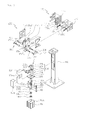
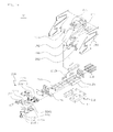
- FIG. 2 is a perspective view of an apparatus for replacing the welding tip of a spot welding gun in accordance with a first embodiment of the present invention
- FIG. 3 is an exploded perspective view of the apparatus for replacing the welding tip of a spot welding gun illustrated in FIG. 2
- FIG. 4 is an exploded perspective view of tip removal means illustrated in FIG. 2
- FIG. 5 is an exploded perspective view of tip setting means illustrated in FIG. 2
- FIG. 6 is a diagram schematically illustrating the state in which the apparatus for replacing the welding tip of a spot welding gun in accordance with the first embodiment of the present invention is used
- FIG. 7 is a diagram schematically illustrating an operation of removing, by the removal means, a welding tip in accordance with the first embodiment of the present invention.
- the apparatus 100 for replacing the welding tip of a spot welding gun 100 in accordance with the first embodiment of the present invention is configured to include a post frame 110, tip removal means 120, and tip setting means 150.
- a connection plate 112 is provided on top of the post frame 110.
- the tip removal means 120 is combined with one side of the post frame 110, and removes a welding tip 20 combined with the tip of the shank 12 of a spot welding gun 10.
- such tip removal means 120 is configured to include a main body 122 combined with one side of the post frame 110 at a specific location thereof in a length direction, a cylinder 146 installed at the bottom of the main body 122, and a tip removal unit 136 combined with one end of the cylinder 146 and placed to slide and move within the main body 122.
- the main body 122 is configured to include a vertical unit 124 combined with one side of the post frame 110, a horizontal unit 126 that is horizontally protruded and formed under the vertical unit 124 and that has a through hole 126a formed at a central part thereof, a body 130 including first and second extension units 128, 129 that are spaced apart from each other at a specific distance, protruded, and formed in a length direction on one side of the vertical unit 124 and that include a first through hole 128a and a second through hole 129a, respectively, at the centers of the first and second extension units, a setting block 132 that is combined with the vertical unit 124 so that the setting block 132 is placed between the first and the second extension units 128, 129 and that comprises a pair of stoppers 132a on both sides of the setting block 132, and a cover 134 combined with the body 130.
- the setting block 132 limits the location of the welding tip 20 that is removed from the tip of the shank 12 of the spot welding gun 10 by the tip removal unit 136 to be described later.
- the stoppers 132a prevent a body 138 that makes the tip removal unit 136 to slide and move within the main body 122 146 from being rotated by the cylinder.
- the pair of stoppers 132a provided on both sides of the setting block 132 limits the distance that the pair of guides 140 goes up and down, and fixes the tip of the shank 12 of the spot welding gun 10 to a 'U'-shaped groove 140a formed at the top of a pair of guides 140.
- An incision part 134a is formed at a specific location of the central part of the cover 134.
- the incision part 134a is combined with the tip of the shank 12 of the spot welding gun 10, and provides space in which the tip of the shank 12 of the spot welding gun 10 may be inserted into the tip removal means 120 so that the welding tip 20 can be removed by the tip removal means 120. Accordingly, the welding tip 20 removed from the tip of the shank 12 of the spot welding gun 10 by the tip removal means 120 is received in a tip collection tank 135 installed on one side of the cover 134.
- the tip removal unit 136 is configured to include the body 138, the pair of guides 140, a guide block 142, and a spring 144.
- the body 138 includes space therein and includes a plurality of incision parts 138a that is formed on the outside of the body and that communicates with the space in a circumferential direction thereof.
- a pair of guide projections 138b is downward slantly protruded and formed on both sides of the inside of incision parts 138a that belong to the plurality of incision parts 138a and that are formed at the front and rear of the body 138 on the basis of the drawing.
- the pair of guide projections 138b enables the welding tip 20, combined with the tip of the shank 12 of the spot welding gun 10, to be removed from the tip of the shank when the body 138 is raised by the cylinder 146 in the state in which the tip of the shank 12 of the spot welding gun 10 combined with the welding tip 20 is inserted and fixed between the stoppers 132a and the 'U' -shaped groove 140a formed at the top of the pair of guides 140 over the incision parts 138a formed on the right and left faces of the body 138.
- the pair of guides 140 is combined with guide grooves 139 formed in the length direction of the body 138 on the left and right sides of the body 138 in such a way as to slide and move.
- the 'U' -shaped groove 140a is formed at the top of the pair of guides 140.
- the guide block 142 is placed within the body 138, and has both sides combined with and fixed to respective one sides of the pair of guides 140.
- the spring 144 has one end supported by a flange unit 138d that is formed in the outer circumference surface of an extension unit 138c extended and formed under the body 138 and has the other end configured to be supported by a guide ring 146b that is inserted into a cylinder rod 146a provided in the cylinder 146, thus applying elastic force to the pair of guides 140.
- the tip setting means 150 functions to combine the welding tip 20 with the tip of the shank 12 of the spot welding gun 10.
- the tip setting means 150 is configured to include a body 152 combined with a top surface of the connection plate 112, a tip accommodation unit 154 formed within the body 152 in the height direction of the body 152, a tip input hole 156 formed at a specific location of the top surface of the body 152 in such a way as to communicate with the tip accommodation unit 154, and covers 158 combined with both sides of the body 152.
- the tip accommodation unit 154 is formed in a form, such as an 'S', 'M', or 'W' shape.
- the tip accommodation unit 154 preferably is configured so that the welding tip 20 input through the tip input hole 156 can be moved from the top of the tip accommodation unit 154 to the bottom due to its own weight.
- the body 152 is combined in such a way as to reciprocate in the width direction of the connection plate 112 by an equalizer member 160 that is provided on a top surface of the connection plate 112. In such a case, an error that may occur when the tip of the shank 12 of the spot welding gun 10 is inserted into the lower part of the tip accommodation unit 154 and thus the welding tip 20 is combined with the tip of the shank 12 is corrected.
- Such an equalizer member 160 is configured to include a pair of fixation plates 162 installed on a top surface of the connection plate 112 with the body 152 interposed between the pair of fixation plates 162, shafts 164 inserted into respective through holes 152a spaced apart from each other at a specific distance in a width direction thereof under the body 152 in such a way as to penetrate the through holes 152a and each configured to have both ends combined with the pair of fixation plates 162, and coil springs 166 that are placed between the body 152 and the fixation plates 162 and that apply elastic force to the body 152.
- alien substance prevention covers for preventing an alien substance from being attached to the coil springs 166 may be installed outside the coil springs 166.
- the alien substance prevention cover preferably is made in a bellow type that corresponds to the shape of the coil spring 166.
- miss-input prevention bracket 156a is installed on one side of the input hole 156.
- the miss-input prevention bracket 156a prevents the welding tip 20 from being input to the tip accommodation unit 154 through the tip input hole 156 when the input direction of a welding tip supplied to the tip accommodation unit 154 through the tip input hole 156 is reversed.
- tip supply means 170 for supplying the welding tip 20 to the tip setting means 150 is installed on top of the tip setting means 150.
- such tip supply means 170 is configured to include a body 172 having a tip storage unit 172a formed therein in a height direction thereof, an opening 174 formed at a specific location of the bottom of the body 172 in such a way as to communicate with the tip storage unit 172a, an opening and closing lever 178 that is rotatably hinged and combined with an incision part 176 formed at the bottom of the body 172 from the opening 174 in the length direction and that opens and closes the opening 174, and covers 179 combined with both sides of the body 172.
- the tip storage unit 172a is configured to have a shape, such as an 'S', 'M', or 'W' shape.
- the tip storage unit 172a preferably is configured so that the welding tip 20 input through the opening 174 can be moved from the top of the tip storage unit 172a to the bottom due to its own weight.
- a spring 178a is provided between the bottom of the incision part 176 and the opening and closing lever 178.
- the spring 178a applies elastic force to the opening and closing lever 178 so that the opening and closing lever 178 may be elastically and rotatably moved.
- At least one location setting block 180 is provided at the bottom of the body 172 and is spaced apart from the opening and closing lever 178 at a specific distance.
- the location setting block 180 provides guidance to the tip supply means 170 so that it is precisely combined with a top surface of the tip setting means 150.
- the location setting block 180 provided at the bottom of the body 172 of the tip supply means 170 is seated in a seating groove 152b provided to face the input hole 156 formed at the top surface of the tip setting means 150.
- the opening and closing lever 178 has one end brought in contact with a top surface of the body 152 of the tip setting means 150 and the other end inserted into accommodation grooves 153 formed between the input hole 156 and the seating grooves 152b that are formed at the top surface of the body 152 of the tip setting means 150.
- the opening and closing lever 178 when one end of the opening and closing lever 178 comes in contact with the top surface of the body 152 of the tip setting means 150, the other end of the opening and closing lever 178 is inserted into the accommodation grooves 153 formed between the input hole 156 and the seating groove 152b that are formed at the top surface of the body 152 of the tip setting means 150. Accordingly, the closed input hole 156 is opened by the opening and closing lever 178, and thus the welding tip is smoothly supplied from the tip supply means 170 to the tip setting means 150.
- tip dressing means 250 capable of dressing the welding tip 20 combined with the tip of the shank 12 of the spot welding gun 10 is installed on one side of the post frame 110.
- the tip dressing means 250 is a known art, and a detailed description thereof is omitted.
- a dressing support 252 for accommodating the cutting powder of the welding tip 20 dressed by the tip dressing means 250 preferably is provided at the lower part of the tip dressing means 250.
- dressing sensors 260 for checking the dressing state of the welding tip 20 by measuring the color of the welding tip 20 dressed by the tip dressing means 250 are provided at specific locations on a top surface of the tip dressing means 250.
- a color analysis sensor preferably is used.
- Such a dressing sensor 260 determines that the dressing state of the welding tip 20 is normal if the color of the dressed face of the welding tip 20 is yellow, and determines that the dressing state of the welding tip 20 is poor if the color of the dressed face of the welding tip 20 is black.
- a method of checking the dressing state of the welding tip 20 includes dressing the welding tip 20, moving the spot welding gun 10 to the dressing sensors 260 so that the welding tip 20 combined with the tip of the shank 12 is placed at the dressing sensors 260, and then sensing the dressed face of the welding tip 20.
- the opening and closing lever 178 that closes the opening 174 formed to communicate with the tip storage unit 172a so that the welding tip 20 is stored in the tip storage unit 172a formed within the body 172 of the tip supply means 170 in a height direction is rotatably moved.
- the welding tip 20 is supplied through the opening 174 so that it is stored in the tip storage unit 172a and the tip supply means 170 is combined with the top of the tip setting means 150, the welding tip 20 stored in the tip storage unit 172a is supplied to the tip accommodation unit 154 of the tip setting means 150.
- the welding tip 20 combined with the tip of the shank 12 is removed by moving the tip of the shank 12 of the spot welding gun 10 through the tip removal means 120.
- the welding tip 20 combined with the tip of the shank 12 of the spot welding gun 10 is removed from the tip of the shank 12 by the guide projections 138b that are downward slantly protruded and formed on both sides of the inside of the incision parts 138a formed at the front and rear of the body 138.
- the welding tip 20 is removed from the tip of the shank 12, when the spot welding gun 10 is moved to the tip setting means 150 and the tip of the shank 12 is inserted into the lower part of the tip accommodation unit 154, the welding tip 20 received in the tip accommodation unit 154 is combined with the tip of the shank 12, thereby completing the replacement of the welding tip 20.
- the apparatus for replacing the welding tip of the spot welding gun in accordance with the first embodiment of the present invention has advantages in that workability and productivity can be improved and a safety accident can be prevented because the welding tip of the spot welding gun is automatically replaced.
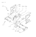
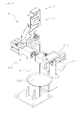
- FIG. 8 is a perspective view of an apparatus for replacing the welding tip of a spot welding gun in accordance with a second embodiment of the present invention
- FIG. 9 is an exploded perspective view of the apparatus for replacing the welding tip of a spot welding gun illustrated in FIG. 8
- FIG. 10 is an exploded perspective view of tip setting means illustrated in FIG. 8
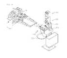
- FIG. 11 is a diagram schematically illustrating the state in which the apparatus for replacing the welding tip of a spot welding gun in accordance with the second embodiment of the present invention is used.
- the apparatus 100 for replacing the welding tip of a spot welding gun in accordance with the second embodiment of the present invention illustrated in FIGS. 8 to 11 is almost the same as the first embodiment illustrated in FIGS. 2 to 7 except that the tip setting means 190 combined with the connection plate 112 provided at a top surface of the post frame 110.
- the tip setting means 190 of the apparatus 100 for replacing the welding tip of a spot welding gun in accordance with the second embodiment of the present invention is configured to include a body 192, a tip transfer unit 210, and a tip fixation unit 220.
- the body 192 includes a tip accommodation unit 194 formed in the height direction of the body, a tip input hole 196 formed at a specific location on a top surface of the body in such a way as to communicate with the tip accommodation unit 194, and covers 198 combined with both sides of the body.
- the tip accommodation unit 194 is configured in a shape, such as an 'S', 'M', or 'W' shape.
- the tip accommodation unit 194 preferably is configured so that the welding tip 20 input through the tip input hole 196 can be moved from the top of the tip accommodation unit 194 to the bottom due to its own weight.
- an incision part 200 is formed at a specific location on the lower part of the tip accommodation unit 194 that faces the tip input hole 196.
- a finger stop 202 for selectively supplying the tip transfer unit 210 with the welding tip received in the tip accommodation unit 194 is rotatably installed in the incision part 200.
- a miss-input prevention bracket 196a for preventing the welding tip 20 from being input to the tip accommodation unit 194 through the tip input hole 196 when the input direction of the welding tip 20 supplied to the tip accommodation unit 194 through the tip input hole 196 is reversed is installed on one side of the tip input hole 196.
- the tip transfer unit 210 has one end combined with the bottom of the body 192 and the other end combined with a top surface of the connection plate 112.
- Such a tip transfer unit 210 is configured to include a base 212, a pair of slide bars 214, a guide block 216, and a cylinder 218.
- the base 212 is combined with a top surface of the connection plate 112.
- the base 212 includes a pair of guide grooves 212a formed on a top surface of the base in the length direction thereof and an extension unit 212b upwardly protruded and formed from one side of the pair of guide grooves 212a.
- the pair of slide bars 214 is inserted into the pair of guide grooves 212a in such a way as to slide and move, and transfers the welding tip, discharged from the tip accommodation unit 194 of the body 192, to the tip fixation unit 220.
- the guide block 216 is combined with one side of the base 212, and changes the direction of the welding tip 20 discharged from the tip accommodation unit 194 of the body 192. That is, the guide block 216 changes the direction of the welding tip 20 so that both ends of the welding tip 20 discharged from the tip accommodation unit 194 with both ends being horizontally placed stand up straight in a vertical direction and that the welding tip 20 is placed at the tip of the pair of slide bars 214.
- the cylinder 218 is combined with the other side of the base 212, and transfers driving power to the pair of slide bars 214 so that they slide and move along the pair of guide grooves 212a.
- the tip fixation unit 220 is combined with one side of the tip transfer unit 210, and fixes the welding tip 20 transferred by the tip transfer unit 210 so that the welding tip 20 is combined with the tip of the shank 12 of the spot welding gun 10.
- Such a tip fixation unit 220 is configured to include a fixation block 222, a location setting member 228, and a location correction member 234.
- the fixation block 222 includes a first fixation unit 224 on a top surface of which a first insertion groove 224a into which any one of the pair of slide bars 214 may be inserted is formed and a second fixation unit 226 combined with the first fixation unit 224 on one side of the first fixation unit 224 in such a way as to cross the first fixation unit 224 and configured to have a second insertion groove (not illustrated) into which another side bar 214 is inserted formed at the bottom of the second fixation unit 226.
- the location setting member 228 is installed on one side of the inside of each of the first insertion groove 224a and the second insertion groove, and corrects the location of the welding tip that is transferred to the first insertion groove 224a and the second insertion groove by the pair of slide bars 214.
- Such a location setting member 228 is configured to include a pair of location setting blocks 230 inserted into and installed at the first insertion groove 224a and the second insertion groove and springs 232 that have one ends supported by the insides of the first insertion groove 224a and the second insertion groove and the other ends supported by the respective ends of the pair of location setting blocks 230 and that apply elastic force to the pair of location setting blocks 230.
- the location correction member 234 is installed at each of a first through hole (not illustrated) and a second through hole 226b formed at specific locations of the bottom of the first fixation unit 224 and the top of the second fixation unit 226 in such a way as to communicate with the first insertion groove 224a and the second insertion groove.
- Such a location correction member 234 is configured to include a pair of location correction blocks 236 inserted into the first through hole and the second through hole 226b, respectively, a pair of control nuts 238 screwed to the first through hole and the second through hole 226b, and a spring 240 that has one end supported by the ends of the pair of location correction blocks 236 and the other end supported by the ends of the pair of control nuts 238 and that applies elastic force to the pair of location correction blocks 236.
- the pair of control nuts 238 controls the elastic force applied to the pair of location correction blocks 236 through the spring 240.
- the present invention is directed to an apparatus for replacing the welding tip of a spot welding gun. More particularly, the present invention may be used for an apparatus for replacing the welding tip of a spot welding gun, which is capable of automatically replacing the welding tip of a spot welding gun.
Landscapes
- Engineering & Computer Science (AREA)
- Mechanical Engineering (AREA)
- Resistance Welding (AREA)
- Electric Connection Of Electric Components To Printed Circuits (AREA)
- Coating Apparatus (AREA)
Abstract
Description
- The present invention relates to an apparatus for replacing the welding tip of a spot welding gun. More particularly, the present invention relates to an apparatus for replacing the welding tip of a spot welding gun, which is capable of automatically replacing the welding tip of a spot welding gun.
- In general, in quantity production for a specific product as in a vehicle product line, spot welding in which a welding part has high stability is chiefly used because the heating time is very short and working speed is fast compared to other welding and residual stress or deformation is small due to a narrow heating range.
- Spot welding is welding in which point bonding is performed on a sheet without perforating a hole in the sheet, such as a riveted joint, by generating melting in contact parts using the generation of heat according to electric resistance and bonding the contact parts using pressure.
- In general, spot welding is performed using a robot on which a welding gun is mounted. The welding gun includes a body installed through the medium of a frame combined with a robot arm and configured to have a timer, a contactor, a transformer, etc. for welding embedded, a shank 1 installed to face the bottom of the body and the top of the arm rotatably installed in the body by a hinge shaft, and a welding tip (or a tip) 2 that is attached to the end of the shank 1 and at which welding is performed.
-
FIG. 1 is a diagram illustrating a conventional method of changing the tip of a robot welding gun. - In order to change the tip of a welding robot used in a current vehicle body manufacturing plant for vehicles, the tip is changed using a tool as illustrated in
FIG. 1 . - To this end, a worker drives a safety device before entering a vehicle body product line, stops the operation of the welding robot, and separates the
tip 2 from the shank 1 of the welding gun of the robot using a pipe wrench or a tip-dedicated tool. Furthermore, a worker mounts a new tip using the tool, checks the new tip, drives the robot, and checks the state of the new tip. - When such a tip change task is performed, the time taken to replace a tip is relatively long because a worker enters the manufacturing line and directly changes the tip in a non-operation time. Furthermore, although safety conditions are thoroughly observed, there may be a problem in that a big accident is caused because another worker drives a robot, resulting in a safety problem.
- Furthermore, since tip change workability is different depending on the location of the welding gun of the robot, it is inconvenient to move the welding gun to a place where a task is easy before replacing a tip. As a result, there is a disadvantage in that the working time is increased.
- Furthermore, if a tip needs to be replaced when a vehicle body product line is driven, the operation must be stopped while a worker replaces the tip. Accordingly, there are problems in that productivity is reduced due to non-operation factors and personal expenses attributable to working hours are increased.
- Furthermore, the prior art is problematic in that welding quality is deteriorated because the tip of the shank combined with the tip is deformed by external force that is generated when the tip is separated from the shank of the welding gun of the robot using a tool.
- Accordingly, the present invention has been made to solve the problems, and an object of the present invention is to provide an apparatus for replacing the welding tip of a spot welding gun, which is capable of improving workability and productivity and preventing a safety accident by automatically replacing the welding tip of a spot welding gun.
- In order to achieve the above and other objects of the present invention, in accordance with an embodiment of the present invention, there is provided an apparatus for replacing the welding tip of a spot welding gun, which is configured to include a post frame on a top surface of which a connection plate is provided; tip removal means combined with one side of the post frame at a specific location of the one side; and tip setting means combined with a top surface of the connection plate.
- Tip supply means for supplying the welding tip to the tip setting means is installed on top of the tip setting means.
- The tip supply means is configured to include a body having a tip storage unit formed therein in the height direction thereof; an opening formed at a specific location of the bottom of the body in such a way as to communicate with the tip storage unit; an opening and closing lever that is rotatably hinged and combined with an incision part formed at the bottom of the body from the opening in the length direction and that opens and closes the opening; and covers combined with both sides of the body.
- At least one location setting block spaced apart from the opening and closing lever at a specific distance is provided at the bottom of the body.
- The tip setting means is configured to include a body combined with the top surface of the connection plate; a tip accommodation unit formed within the body in the height direction of the body; a tip input hole formed at a specific location of the top surface of the body in such a way as to communicate with the tip accommodation unit; and covers combined with both sides of the body.
- The body is combined with the top surface of the connection plate in such a way as to reciprocate in the width direction of the connection plate by an equalizer member provided on the top surface of the connection plate.
- The equalizer member is configured to include a pair of fixation plates installed on the top surface of the connection plate with the body interposed between the pair of fixation plates; shafts inserted into respective through holes, spaced apart from each other at a specific distance, in the width direction of the shafts under the body in such a way as to penetrate the through holes and each configured to have both ends combined with the pair of fixation plates; and coil springs that are placed between the body and the fixation plates and that apply elastic force to the body.
- The tip removal means is configured to include a main body combined with a specific location on one side of the post frame in a length direction; a cylinder installed at the bottom of the main body; and a tip removal unit combined with one end of the cylinder and placed to slide and move within the main body.
- The main body is configured to include a vertical unit combined with the one side of the post frame; a horizontal unit that is horizontally protruded and formed under the vertical unit and that has a through hole formed at the central part of the horizontal unit; a body including first and second extension units that are spaced apart from each other at a specific distance, protruded, and formed in the length direction of the body on one side of the vertical unit and that include a first through hole and a second through hole, respectively, at the centers of the first and second extension units; a setting block that is combined with the vertical unit so that the setting block is placed between the first and the second extension units and that includes a pair of stoppers on both sides of the setting block; and a cover combined with the body.
- A tip collection tank is combined with one side of the cover.
- The tip removal unit is configured to include a body that includes space therein and incision parts that are formed on the outside of the body and that communicate with the space in the circumferential direction of the body; a pair of guides having respective U-shaped grooves formed on upper parts of the guides and combined with guide grooves formed in the length direction of the body on left and right sides of the body in such a way as to slide and move; a guide block that is placed within the space the body and has both sides combined with and fixed to the respective one sides of the pair of guides; and a spring having one end supported by a flange unit that is provided on an outer circumference surface of an extension unit extended and formed under the body and the other end supported by a guide ring that is inserted into a cylinder rod provided in the cylinder.
- A pair of guide projections is downward slantly protruded and formed on both sides of an inside of incision parts that belong to the incision parts and that are formed at a front and rear of the body.
- The tip setting means is configured to include a body including a tip accommodation unit formed in the height direction of the body, a tip input hole formed at a specific location on a top surface of the body in such a way as to communicate with the tip accommodation unit, and covers combined with both sides of the body; a tip transfer unit having one end combined with the bottom of the body and the other end combined with the top surface of the connection plate; and a tip fixation unit that is combined with one side of the tip transfer unit and that fixes the
welding tip 20 transferred by the tip transfer unit. - The tip transfer unit is configured to include a base that is combined with the top surface of the connection plate and that includes a pair of guide grooves formed on a top surface of the base in the length direction of the base and an extension unit upwardly protruded and formed from one side of the pair of guide grooves; a pair of slide bars inserted into the pair of guide grooves in such a way as to slide and move; a guide block combined with one side of the base; and a cylinder that is combined with the other side of the base and that moves the pair of slide bars along the pair of guide grooves in a sliding way.
- The tip fixation unit is configured to include a fixation block including a first fixation unit on a top surface of which a first insertion groove into which any one of the pair of slide bars is able to be inserted is formed and a second fixation unit combined with the first fixation unit on one side of the first fixation unit in such a way as to cross the first fixation unit and configured to have a second insertion groove into which another side bar is inserted formed at the bottom of the second fixation unit; a location setting member that is installed on one side of an inside of each of the first insertion groove and the second insertion groove and that corrects the location of the welding tip transferred to the first insertion groove and the second insertion groove by the pair of slide bars; and a location correction member installed at each of a first through hole and a second through hole formed at specific locations of the bottom of the first fixation unit and a top of the second fixation unit in such a way as to communicate with the first insertion groove and the second insertion groove.
- An incision part is formed at a specific location on the lower part of the tip accommodation unit that faces the tip input hole, and a finger stop that selectively supplies the tip transfer unit with the welding tip received in the tip accommodation unit is rotatably installed in the incision part.
- A miss-input prevention bracket that prevents the welding tip from being input to the tip accommodation unit through the tip input hole when the input direction of the welding tip supplied to the tip accommodation unit through the tip input hole is reversed is installed on one side of the tip input hole.
- Tip dressing means is installed on one side of the post frame.
- Dressing sensors that check a dressing state of the welding tip by measuring a color of the welding tip dressed by the tip dressing means are provided at specific locations on a top surface of the tip dressing means.
- In accordance with the present invention having the aforementioned construction, there are advantages in that workability and productivity can be improved and a safety accident can be prevented because the welding tip of a spot welding gun can be automatically replaced.
-
-
FIG. 1 is a diagram illustrating a conventional method for replacing the tip of a robot welding gun. -
FIG. 2 is a perspective view of an apparatus for replacing the welding tip of a spot welding gun in accordance with a first embodiment of the present invention. -
FIG. 3 is an exploded perspective view of the apparatus for replacing the welding tip of a spot welding gun illustrated inFIG. 2 . -
FIG. 4 is an exploded perspective view of tip removal means illustrated inFIG. 2 . -
FIG. 5 is an exploded perspective view of tip setting means illustrated inFIG. 2 . -
FIG. 6 is a diagram schematically illustrating the state in which the apparatus for replacing the welding tip of a spot welding gun in accordance with the first embodiment of the present invention is used. -
FIG. 7 is a diagram schematically illustrating an operation of removing, by the removal means, a welding tip in accordance with the first embodiment of the present invention. -
FIG. 8 is a perspective view of an apparatus for replacing the welding tip of a spot welding gun in accordance with a second embodiment of the present invention. -
FIG. 9 is an exploded perspective view of the apparatus for replacing the welding tip of a spot welding gun illustrated inFIG. 8 . -
FIG. 10 is an exploded perspective view of tip setting means illustrated inFIG. 8 . -
FIG. 11 is a diagram schematically illustrating the state in which the apparatus for replacing the welding tip of a spot welding gun in accordance with the second embodiment of the present invention is used. -
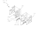
FIG. 12 is an exploded perspective view of tip supply means in accordance with the first and the second embodiments of the present invention. -
- 110:
- post frame
- 112:
- connection plate
- 120:
- tip removal means
- 135:
- tip collection tank
- 136:
- tip removal unit
- 150:
- tip setting means
- 160:
- equalizer member
- 170:
- tip supply means
- 180:
- location setting block
- 190:
- tip setting means
- 210:
- tip transfer unit
- 220:
- tip fixation unit
- 228:
- location correction member
- 234:
- location setting member
- Hereinafter, preferred embodiments of the present invention are described in more detail with reference to the accompanying drawings. The thickness of lines and the size of elements illustrated in the drawings may have been enlarged for the clarity of descriptions and for convenience' sake.
- Furthermore, terms to be described later are defined by taking into consideration the functions of the embodiments of the present invention, and may be different according to the operator's intention or usage. Accordingly, the terms should be defined based on the overall contents of the specification.
-
FIG. 1 is a diagram illustrating a conventional method for replacing the tip of a robot welding gun,FIG. 2 is a perspective view of an apparatus for replacing the welding tip of a spot welding gun in accordance with a first embodiment of the present invention,FIG. 3 is an exploded perspective view of the apparatus for replacing the welding tip of a spot welding gun illustrated inFIG. 2 ,FIG. 4 is an exploded perspective view of tip removal means illustrated inFIG. 2 ,FIG. 5 is an exploded perspective view of tip setting means illustrated inFIG. 2 ,FIG. 6 is a diagram schematically illustrating the state in which the apparatus for replacing the welding tip of a spot welding gun in accordance with the first embodiment of the present invention is used, andFIG. 7 is a diagram schematically illustrating an operation of removing, by the removal means, a welding tip in accordance with the first embodiment of the present invention. - Referring to
FIGS. 2 to 7 , theapparatus 100 for replacing the welding tip of aspot welding gun 100 in accordance with the first embodiment of the present invention is configured to include apost frame 110, tip removal means 120, and tip setting means 150. - A
connection plate 112 is provided on top of thepost frame 110. - The tip removal means 120 is combined with one side of the
post frame 110, and removes awelding tip 20 combined with the tip of theshank 12 of aspot welding gun 10. - Referring to
FIG. 4 , such tip removal means 120 is configured to include amain body 122 combined with one side of thepost frame 110 at a specific location thereof in a length direction, acylinder 146 installed at the bottom of themain body 122, and a tip removal unit 136 combined with one end of thecylinder 146 and placed to slide and move within themain body 122. - The
main body 122 is configured to include avertical unit 124 combined with one side of thepost frame 110, ahorizontal unit 126 that is horizontally protruded and formed under thevertical unit 124 and that has a throughhole 126a formed at a central part thereof, abody 130 including first andsecond extension units vertical unit 124 and that include a first throughhole 128a and a second throughhole 129a, respectively, at the centers of the first and second extension units, asetting block 132 that is combined with thevertical unit 124 so that thesetting block 132 is placed between the first and thesecond extension units stoppers 132a on both sides of thesetting block 132, and acover 134 combined with thebody 130. - In this case, the
setting block 132 limits the location of thewelding tip 20 that is removed from the tip of theshank 12 of thespot welding gun 10 by the tip removal unit 136 to be described later. Thestoppers 132a prevent abody 138 that makes the tip removal unit 136 to slide and move within themain body 122 146 from being rotated by the cylinder. - Furthermore, the pair of
stoppers 132a provided on both sides of thesetting block 132 limits the distance that the pair ofguides 140 goes up and down, and fixes the tip of theshank 12 of thespot welding gun 10 to a 'U'-shapedgroove 140a formed at the top of a pair ofguides 140. - An
incision part 134a is formed at a specific location of the central part of thecover 134. Theincision part 134a is combined with the tip of theshank 12 of thespot welding gun 10, and provides space in which the tip of theshank 12 of thespot welding gun 10 may be inserted into the tip removal means 120 so that thewelding tip 20 can be removed by the tip removal means 120. Accordingly, thewelding tip 20 removed from the tip of theshank 12 of thespot welding gun 10 by the tip removal means 120 is received in atip collection tank 135 installed on one side of thecover 134. - The tip removal unit 136 is configured to include the
body 138, the pair ofguides 140, aguide block 142, and aspring 144. - The
body 138 includes space therein and includes a plurality ofincision parts 138a that is formed on the outside of the body and that communicates with the space in a circumferential direction thereof. - In this case, a pair of
guide projections 138b is downward slantly protruded and formed on both sides of the inside ofincision parts 138a that belong to the plurality ofincision parts 138a and that are formed at the front and rear of thebody 138 on the basis of the drawing. - The pair of
guide projections 138b enables thewelding tip 20, combined with the tip of theshank 12 of thespot welding gun 10, to be removed from the tip of the shank when thebody 138 is raised by thecylinder 146 in the state in which the tip of theshank 12 of thespot welding gun 10 combined with thewelding tip 20 is inserted and fixed between thestoppers 132a and the 'U' -shapedgroove 140a formed at the top of the pair ofguides 140 over theincision parts 138a formed on the right and left faces of thebody 138. - The pair of
guides 140 is combined withguide grooves 139 formed in the length direction of thebody 138 on the left and right sides of thebody 138 in such a way as to slide and move. The 'U' -shapedgroove 140a is formed at the top of the pair ofguides 140. - The
guide block 142 is placed within thebody 138, and has both sides combined with and fixed to respective one sides of the pair ofguides 140. - The
spring 144 has one end supported by aflange unit 138d that is formed in the outer circumference surface of anextension unit 138c extended and formed under thebody 138 and has the other end configured to be supported by aguide ring 146b that is inserted into acylinder rod 146a provided in thecylinder 146, thus applying elastic force to the pair ofguides 140. - Referring to
FIG. 5 , the tip setting means 150 functions to combine thewelding tip 20 with the tip of theshank 12 of thespot welding gun 10. The tip setting means 150 is configured to include abody 152 combined with a top surface of theconnection plate 112, atip accommodation unit 154 formed within thebody 152 in the height direction of thebody 152, atip input hole 156 formed at a specific location of the top surface of thebody 152 in such a way as to communicate with thetip accommodation unit 154, and covers 158 combined with both sides of thebody 152. - In this case, the
tip accommodation unit 154 is formed in a form, such as an 'S', 'M', or 'W' shape. Thetip accommodation unit 154 preferably is configured so that thewelding tip 20 input through thetip input hole 156 can be moved from the top of thetip accommodation unit 154 to the bottom due to its own weight. - Furthermore, the
body 152 is combined in such a way as to reciprocate in the width direction of theconnection plate 112 by anequalizer member 160 that is provided on a top surface of theconnection plate 112. In such a case, an error that may occur when the tip of theshank 12 of thespot welding gun 10 is inserted into the lower part of thetip accommodation unit 154 and thus thewelding tip 20 is combined with the tip of theshank 12 is corrected. - Such an
equalizer member 160 is configured to include a pair offixation plates 162 installed on a top surface of theconnection plate 112 with thebody 152 interposed between the pair offixation plates 162,shafts 164 inserted into respective throughholes 152a spaced apart from each other at a specific distance in a width direction thereof under thebody 152 in such a way as to penetrate the throughholes 152a and each configured to have both ends combined with the pair offixation plates 162, andcoil springs 166 that are placed between thebody 152 and thefixation plates 162 and that apply elastic force to thebody 152. - In this case, alien substance prevention covers (not illustrated) for preventing an alien substance from being attached to the coil springs 166 may be installed outside the coil springs 166. The alien substance prevention cover preferably is made in a bellow type that corresponds to the shape of the
coil spring 166. - Furthermore, a miss-
input prevention bracket 156a is installed on one side of theinput hole 156. The miss-input prevention bracket 156a prevents thewelding tip 20 from being input to thetip accommodation unit 154 through thetip input hole 156 when the input direction of a welding tip supplied to thetip accommodation unit 154 through thetip input hole 156 is reversed. - Moreover, tip supply means 170 for supplying the
welding tip 20 to the tip setting means 150 is installed on top of the tip setting means 150. - Referring to
FIG. 12 , such tip supply means 170 is configured to include abody 172 having atip storage unit 172a formed therein in a height direction thereof, anopening 174 formed at a specific location of the bottom of thebody 172 in such a way as to communicate with thetip storage unit 172a, an opening and closinglever 178 that is rotatably hinged and combined with anincision part 176 formed at the bottom of thebody 172 from theopening 174 in the length direction and that opens and closes theopening 174, and covers 179 combined with both sides of thebody 172. - In this case, the
tip storage unit 172a is configured to have a shape, such as an 'S', 'M', or 'W' shape. Thetip storage unit 172a preferably is configured so that thewelding tip 20 input through theopening 174 can be moved from the top of thetip storage unit 172a to the bottom due to its own weight. - In this case, a
spring 178a is provided between the bottom of theincision part 176 and the opening and closinglever 178. Thespring 178a applies elastic force to the opening and closinglever 178 so that the opening and closinglever 178 may be elastically and rotatably moved. - Moreover, at least one
location setting block 180 is provided at the bottom of thebody 172 and is spaced apart from the opening and closinglever 178 at a specific distance. Thelocation setting block 180 provides guidance to the tip supply means 170 so that it is precisely combined with a top surface of the tip setting means 150. - That is, when the tip supply means 170 is combined with the top surface of the tip setting means 150 so that the
welding tip 20 received in thetip storage unit 172a of the tip supply means 170 is supplied to thetip accommodation unit 154 of the tip setting means 150, the location setting block 180 provided at the bottom of thebody 172 of the tip supply means 170 is seated in aseating groove 152b provided to face theinput hole 156 formed at the top surface of the tip setting means 150. - At the same time, the opening and closing
lever 178 has one end brought in contact with a top surface of thebody 152 of the tip setting means 150 and the other end inserted intoaccommodation grooves 153 formed between theinput hole 156 and theseating grooves 152b that are formed at the top surface of thebody 152 of the tip setting means 150. - That is, when one end of the opening and closing
lever 178 comes in contact with the top surface of thebody 152 of the tip setting means 150, the other end of the opening and closinglever 178 is inserted into theaccommodation grooves 153 formed between theinput hole 156 and theseating groove 152b that are formed at the top surface of thebody 152 of the tip setting means 150. Accordingly, theclosed input hole 156 is opened by the opening and closinglever 178, and thus the welding tip is smoothly supplied from the tip supply means 170 to the tip setting means 150. - Meanwhile, tip dressing means 250 capable of dressing the
welding tip 20 combined with the tip of theshank 12 of thespot welding gun 10 is installed on one side of thepost frame 110. The tip dressing means 250 is a known art, and a detailed description thereof is omitted. - Moreover, a
dressing support 252 for accommodating the cutting powder of thewelding tip 20 dressed by the tip dressing means 250 preferably is provided at the lower part of the tip dressing means 250. - Furthermore, dressing
sensors 260 for checking the dressing state of thewelding tip 20 by measuring the color of thewelding tip 20 dressed by the tip dressing means 250 are provided at specific locations on a top surface of the tip dressing means 250. A color analysis sensor preferably is used. - Such a
dressing sensor 260 determines that the dressing state of thewelding tip 20 is normal if the color of the dressed face of thewelding tip 20 is yellow, and determines that the dressing state of thewelding tip 20 is poor if the color of the dressed face of thewelding tip 20 is black. A method of checking the dressing state of thewelding tip 20 includes dressing thewelding tip 20, moving thespot welding gun 10 to the dressingsensors 260 so that thewelding tip 20 combined with the tip of theshank 12 is placed at the dressingsensors 260, and then sensing the dressed face of thewelding tip 20. - The operation of the apparatus for replacing the welding tip of a spot welding gun according to the first embodiment of the present invention is described below.
- First, the opening and closing
lever 178 that closes theopening 174 formed to communicate with thetip storage unit 172a so that thewelding tip 20 is stored in thetip storage unit 172a formed within thebody 172 of the tip supply means 170 in a height direction is rotatably moved. Next, when thewelding tip 20 is supplied through theopening 174 so that it is stored in thetip storage unit 172a and the tip supply means 170 is combined with the top of the tip setting means 150, thewelding tip 20 stored in thetip storage unit 172a is supplied to thetip accommodation unit 154 of the tip setting means 150. - Thereafter, the
welding tip 20 combined with the tip of theshank 12 is removed by moving the tip of theshank 12 of thespot welding gun 10 through the tip removal means 120. - In this case, in a process of removing, by the tip removal means 120, the
welding tip 20 combined with the tip of theshank 12 of thespot welding gun 10, as illustrated inFIG. 7 , when the tip of theshank 12 of thespot welding gun 10 with which thewelding tip 20 is combined is inserted into the top of theincision parts 138a formed on the left and right faces of thebody 138 of the tip removal unit 136, the pair ofguides 140 combined with the left and right faces of thebody 138 in such a way as to slide and move are raised. At the same time, the tip of theshank 12 with which the welding tip is combined is fixed between the 'U'-shapedgroove 140a and thestoppers 132a formed on top of the pair ofguides 140. - Thereafter, when the
body 138 of the tip removal unit 136 is raised by the operation of thecylinder 146, thewelding tip 20 combined with the tip of theshank 12 of thespot welding gun 10 is removed from the tip of theshank 12 by theguide projections 138b that are downward slantly protruded and formed on both sides of the inside of theincision parts 138a formed at the front and rear of thebody 138. - Thereafter, after the
welding tip 20 is removed from the tip of theshank 12, when thespot welding gun 10 is moved to the tip setting means 150 and the tip of theshank 12 is inserted into the lower part of thetip accommodation unit 154, thewelding tip 20 received in thetip accommodation unit 154 is combined with the tip of theshank 12, thereby completing the replacement of thewelding tip 20. - Accordingly, the apparatus for replacing the welding tip of the spot welding gun in accordance with the first embodiment of the present invention has advantages in that workability and productivity can be improved and a safety accident can be prevented because the welding tip of the spot welding gun is automatically replaced.
-
FIG. 8 is a perspective view of an apparatus for replacing the welding tip of a spot welding gun in accordance with a second embodiment of the present invention,FIG. 9 is an exploded perspective view of the apparatus for replacing the welding tip of a spot welding gun illustrated inFIG. 8 ,FIG. 10 is an exploded perspective view of tip setting means illustrated inFIG. 8 , andFIG. 11 is a diagram schematically illustrating the state in which the apparatus for replacing the welding tip of a spot welding gun in accordance with the second embodiment of the present invention is used. - The
apparatus 100 for replacing the welding tip of a spot welding gun in accordance with the second embodiment of the present invention illustrated inFIGS. 8 to 11 is almost the same as the first embodiment illustrated inFIGS. 2 to 7 except that the tip setting means 190 combined with theconnection plate 112 provided at a top surface of thepost frame 110. - Accordingly, redundant descriptions are omitted.
- Referring to
FIGS. 8 to 11 , the tip setting means 190 of theapparatus 100 for replacing the welding tip of a spot welding gun in accordance with the second embodiment of the present invention is configured to include abody 192, atip transfer unit 210, and atip fixation unit 220. - The
body 192 includes atip accommodation unit 194 formed in the height direction of the body, atip input hole 196 formed at a specific location on a top surface of the body in such a way as to communicate with thetip accommodation unit 194, and covers 198 combined with both sides of the body. - In this case, the
tip accommodation unit 194 is configured in a shape, such as an 'S', 'M', or 'W' shape. Thetip accommodation unit 194 preferably is configured so that thewelding tip 20 input through thetip input hole 196 can be moved from the top of thetip accommodation unit 194 to the bottom due to its own weight. - Furthermore, an
incision part 200 is formed at a specific location on the lower part of thetip accommodation unit 194 that faces thetip input hole 196. Afinger stop 202 for selectively supplying thetip transfer unit 210 with the welding tip received in thetip accommodation unit 194 is rotatably installed in theincision part 200. - Moreover, a miss-
input prevention bracket 196a for preventing thewelding tip 20 from being input to thetip accommodation unit 194 through thetip input hole 196 when the input direction of thewelding tip 20 supplied to thetip accommodation unit 194 through thetip input hole 196 is reversed is installed on one side of thetip input hole 196. - The
tip transfer unit 210 has one end combined with the bottom of thebody 192 and the other end combined with a top surface of theconnection plate 112. - Such a
tip transfer unit 210 is configured to include abase 212, a pair of slide bars 214, aguide block 216, and acylinder 218. - The
base 212 is combined with a top surface of theconnection plate 112. Thebase 212 includes a pair ofguide grooves 212a formed on a top surface of the base in the length direction thereof and anextension unit 212b upwardly protruded and formed from one side of the pair ofguide grooves 212a. - The pair of slide bars 214 is inserted into the pair of
guide grooves 212a in such a way as to slide and move, and transfers the welding tip, discharged from thetip accommodation unit 194 of thebody 192, to thetip fixation unit 220. - The
guide block 216 is combined with one side of thebase 212, and changes the direction of thewelding tip 20 discharged from thetip accommodation unit 194 of thebody 192. That is, the guide block 216 changes the direction of thewelding tip 20 so that both ends of thewelding tip 20 discharged from thetip accommodation unit 194 with both ends being horizontally placed stand up straight in a vertical direction and that thewelding tip 20 is placed at the tip of the pair of slide bars 214. - The
cylinder 218 is combined with the other side of thebase 212, and transfers driving power to the pair of slide bars 214 so that they slide and move along the pair ofguide grooves 212a. - The
tip fixation unit 220 is combined with one side of thetip transfer unit 210, and fixes thewelding tip 20 transferred by thetip transfer unit 210 so that thewelding tip 20 is combined with the tip of theshank 12 of thespot welding gun 10. - Such a
tip fixation unit 220 is configured to include a fixation block 222, alocation setting member 228, and alocation correction member 234. - The fixation block 222 includes a
first fixation unit 224 on a top surface of which afirst insertion groove 224a into which any one of the pair of slide bars 214 may be inserted is formed and asecond fixation unit 226 combined with thefirst fixation unit 224 on one side of thefirst fixation unit 224 in such a way as to cross thefirst fixation unit 224 and configured to have a second insertion groove (not illustrated) into which anotherside bar 214 is inserted formed at the bottom of thesecond fixation unit 226. - The
location setting member 228 is installed on one side of the inside of each of thefirst insertion groove 224a and the second insertion groove, and corrects the location of the welding tip that is transferred to thefirst insertion groove 224a and the second insertion groove by the pair of slide bars 214. - Such a
location setting member 228 is configured to include a pair of location setting blocks 230 inserted into and installed at thefirst insertion groove 224a and the second insertion groove and springs 232 that have one ends supported by the insides of thefirst insertion groove 224a and the second insertion groove and the other ends supported by the respective ends of the pair of location setting blocks 230 and that apply elastic force to the pair of location setting blocks 230. - The
location correction member 234 is installed at each of a first through hole (not illustrated) and a second throughhole 226b formed at specific locations of the bottom of thefirst fixation unit 224 and the top of thesecond fixation unit 226 in such a way as to communicate with thefirst insertion groove 224a and the second insertion groove. - Such a
location correction member 234 is configured to include a pair of location correction blocks 236 inserted into the first through hole and the second throughhole 226b, respectively, a pair ofcontrol nuts 238 screwed to the first through hole and the second throughhole 226b, and aspring 240 that has one end supported by the ends of the pair of location correction blocks 236 and the other end supported by the ends of the pair ofcontrol nuts 238 and that applies elastic force to the pair of location correction blocks 236. - In this case, the pair of
control nuts 238 controls the elastic force applied to the pair of location correction blocks 236 through thespring 240. - Although the preferred embodiments of the present invention have been described above, those skilled in the art will appreciate that the present invention may be modified and changed in various ways without departing from the technical spirit and scope of the present invention.
- The present invention is directed to an apparatus for replacing the welding tip of a spot welding gun. More particularly, the present invention may be used for an apparatus for replacing the welding tip of a spot welding gun, which is capable of automatically replacing the welding tip of a spot welding gun.
Claims (19)
- An apparatus for replacing a welding tip of a spot welding gun, comprising:a post frame on a top surface of which a connection plate is provided;tip removal means combined with one side of the post frame at a specific location of the one side; andtip setting means combined with a top surface of the connection plate.
- The apparatus of claim 1, wherein tip supply means for supplying the welding tip to the tip setting means is installed on top of the tip setting means.
- The apparatus of claim 2, wherein the tip supply means is configured to comprise:a body having a tip storage unit formed therein in a height direction thereof;an opening formed at a specific location of a bottom of the body in such a way as to communicate with the tip storage unit;an opening and closing lever that is rotatably hinged and combined with an incision part formed at the bottom of the body from the opening in a length direction and that opens and closes the opening; andcovers combined with both sides of the body.
- The apparatus of claim 3, wherein at least one location setting block spaced apart from the opening and closing lever at a specific distance is provided at the bottom of the body.
- The apparatus of claim 1, wherein the tip setting means is configured to comprise:a body combined with the top surface of the connection plate;a tip accommodation unit formed within the body in a height direction of the body;a tip input hole formed at a specific location of the top surface of the body in such a way as to communicate with the tip accommodation unit; andcovers combined with both sides of the body.
- The apparatus of claim 5, wherein the body is combined with the top surface of the connection plate in such a way as to reciprocate in a width direction of the connection plate by an equalizer member provided on the top surface of the connection plate.
- The apparatus of claim 6, wherein the equalizer member is configured to comprise:a pair of fixation plates installed on the top surface of the connection plate with the body interposed between the pair of fixation plates;shafts inserted into respective through holes, spaced apart from each other at a specific distance, in a width direction of the shafts under the body in such a way as to penetrate the through holes and each configured to have both ends combined with the pair of fixation plates; andcoil springs that are placed between the body and the fixation plates and that apply elastic force to the body.
- The apparatus of claim 1, wherein the tip removal means is configured to comprise:a main body combined with a specific location on one side of the post frame in a length direction;a cylinder installed at a bottom of the main body; anda tip removal unit combined with one end of the cylinder and placed to slide and move within the main body.
- The apparatus of claim 8, wherein the main body is configured to comprise:a body comprising a vertical unit combined with the one side of the post frame, a horizontal unit that is horizontally protruded and formed under the vertical unit and that has a through hole formed at a central part of the horizontal unit, and first and second extension units that are spaced apart from each other at a specific distance, protruded, and formed in a length direction of the body on one side of the vertical unit and that comprise a first through hole and a second through hole, respectively, at centers of the first and second extension units;a setting block that is combined with the vertical unit so that the setting block is placed between the first and the second extension units and that comprises a pair of stoppers on both sides of the setting block; anda cover combined with the body.
- The apparatus of claim 9, wherein a tip collection tank is combined with one side of the cover.
- The apparatus of claim 8, wherein the tip removal unit is configured to comprise:a body that comprises space therein and incision parts that are formed on an outside of the body and that communicate with the space in a circumferential direction of the body;a pair of guides having respective U-shaped grooves formed on upper parts of the guides and combined with guide grooves formed in a length direction of the body on left and right sides of the body in such a way as to slide and move;a guide block that is placed within the space of the body and has both sides combined with and fixed to respective one sides of the pair of guides; anda spring having one end supported by a flange unit that is provided on an outer circumference surface of an extension unit extended and formed under the body and the other end supported by a guide ring that is inserted into a cylinder rod provided in the cylinder.
- The apparatus of claim 11, wherein a pair of guide projections is downward slantly protruded and formed on both sides of an inside of incision parts that belong to the incision parts and that are formed at a front and rear of the body.
- The apparatus of claim 1, wherein the tip setting means is configured to comprise:a body comprising a tip accommodation unit formed in a height direction of the body, a tip input hole formed at a specific location on a top surface of the body in such a way as to communicate with the tip accommodation unit, and covers combined with both sides of the body;a tip transfer unit having one end combined with a bottom of the body and the other end combined with the top surface of the connection plate; anda tip fixation unit that is combined with one side of the tip transfer unit and that fixes the welding tip transferred by the tip transfer unit.
- The apparatus of claim 13, wherein the tip transfer unit is configured to comprise:a base that is combined with the top surface of the connection plate and that comprises a pair of guide grooves formed on a top surface of the base in a length direction of the base and an extension unit upwardly protruded and formed from one side of the pair of guide grooves;a pair of slide bars inserted into the pair of guide grooves in such a way as to slide and move;a guide block combined with one side of the base; anda cylinder that is combined with the other side of the base and that moves the pair of slide bars along the pair of guide grooves in a sliding way.
- The apparatus of claim 14, wherein the tip fixation unit is configured to comprise:a fixation block comprising a first fixation unit on a top surface of which a first insertion groove into which any one of the pair of slide bars is able to be inserted is formed and a second fixation unit combined with the first fixation unit on one side of the first fixation unit in such a way as to cross the first fixation unit and configured to have a second insertion groove into which another side bar is inserted formed at a bottom of the second fixation unit;a location setting member that is installed on one side of an inside of each of the first insertion groove and the second insertion groove and that corrects a location of the welding tip transferred to the first insertion groove and the second insertion groove by the pair of slide bars; anda location correction member installed at each of a first through hole and a second through hole formed at specific locations of a bottom of the first fixation unit and a top of the second fixation unit in such a way as to communicate with the first insertion groove and the second insertion groove.
- The apparatus of claim 14, wherein:an incision part is formed at a specific location on a lower part of the tip accommodation unit that faces the tip input hole, anda finger stop that selectively supplies the tip transfer unit with the welding tip received in the tip accommodation unit is rotatably installed in the incision part.
- The apparatus of claim 5 or 14, wherein a miss-input prevention bracket that prevents the welding tip from being input to the tip accommodation unit through the tip input hole when an input direction of the welding tip supplied to the tip accommodation unit through the tip input hole is reversed is installed on one side of the tip input hole.
- The apparatus of claim 1, wherein tip dressing means is installed on one side of the post frame.
- The apparatus of claim 18, wherein dressing sensors that check a dressing state of the welding tip by measuring a color of the welding tip dressed by the tip dressing means are provided at specific locations on a top surface of the tip dressing means.
Applications Claiming Priority (2)
| Application Number | Priority Date | Filing Date | Title |
|---|---|---|---|
| KR1020120083701A KR101216192B1 (en) | 2012-07-31 | 2012-07-31 | Apparatus for changing welding tip of a spot welding gun |
| PCT/KR2012/010111 WO2014021510A1 (en) | 2012-07-31 | 2012-11-27 | Apparatus for interchanging welding tips of spot welding gun |
Publications (3)
| Publication Number | Publication Date |
|---|---|
| EP2813312A1 true EP2813312A1 (en) | 2014-12-17 |
| EP2813312A4 EP2813312A4 (en) | 2015-12-09 |
| EP2813312B1 EP2813312B1 (en) | 2017-09-20 |
Family
ID=47908369
Family Applications (1)
| Application Number | Title | Priority Date | Filing Date |
|---|---|---|---|
| EP12882379.6A Not-in-force EP2813312B1 (en) | 2012-07-31 | 2012-11-27 | Apparatus for interchanging welding tips of spot welding gun |
Country Status (7)
| Country | Link |
|---|---|
| US (1) | US9908204B2 (en) |
| EP (1) | EP2813312B1 (en) |
| KR (1) | KR101216192B1 (en) |
| CN (1) | CN104220207B (en) |
| BR (1) | BR112014022565B1 (en) |
| RU (1) | RU2607501C2 (en) |
| WO (1) | WO2014021510A1 (en) |
Cited By (1)
| Publication number | Priority date | Publication date | Assignee | Title |
|---|---|---|---|---|
| WO2017018958A1 (en) * | 2015-07-27 | 2017-02-02 | Ford Otomotiv Sanayi A. S. | Robot gun tip changing station |
Families Citing this family (20)
| Publication number | Priority date | Publication date | Assignee | Title |
|---|---|---|---|---|
| KR20130098635A (en) * | 2012-02-28 | 2013-09-05 | 삼성전자주식회사 | Capillary exchange system of semiconductor wire bond |
| KR101310291B1 (en) | 2013-02-13 | 2013-09-24 | 이승해 | Welding tip changer |
| KR101556982B1 (en) * | 2013-12-30 | 2015-10-05 | 주식회사 성우하이텍 | Welding tip change apparatus for spot welding |
| KR101556983B1 (en) * | 2013-12-30 | 2015-10-05 | 주식회사 성우하이텍 | Welding tip change apparatus for spot welding |
| KR101472981B1 (en) * | 2014-05-19 | 2014-12-15 | 최광술 | Apparatus to change welding tips of a welder |
| WO2015178643A1 (en) * | 2014-05-19 | 2015-11-26 | 최광술 | Apparatus for replacing welding tip of welder and apparatus for supplying same |
| CA3204299A1 (en) * | 2014-07-04 | 2016-01-07 | Nasarc Technologies, Inc. | Welding torch maintenance center |
| JP6655923B2 (en) * | 2015-06-09 | 2020-03-04 | 株式会社チップマン | Rotary exchange device for welding torch |
| KR20170013709A (en) | 2015-07-28 | 2017-02-07 | 한국티앤엠(주) | Automatic welding tip exchange device for easy Removing the tip and checking |
| KR20170013716A (en) | 2015-07-28 | 2017-02-07 | 한국티앤엠(주) | Welding Tips steady-state checking device |
| KR101672363B1 (en) | 2015-09-07 | 2016-11-03 | 한국티앤엠(주) | Automatic welding tip cartridge filling device |
| JP7084318B2 (en) * | 2016-05-20 | 2022-06-14 | ナサーク テクノロジーズ インコーポレイテッド | Motion control methods and systems for servicing weld torches |
| KR101847803B1 (en) * | 2016-07-04 | 2018-04-23 | (주)호원 | Pedestal spot welding apparatus |
| US20210252630A1 (en) | 2018-06-12 | 2021-08-19 | Doben Limited | Integrated electrode maintenance for robotic welding cell |
| CA3023116A1 (en) | 2018-11-05 | 2020-05-05 | Nasarc Technologies Inc. | System and method for servicing welding torches |
| JP7306900B2 (en) * | 2019-07-11 | 2023-07-11 | 株式会社Subaru | Welding gun and welding method |
| EP3766621A1 (en) * | 2019-07-15 | 2021-01-20 | Lutz Precision, K.S. | Device for turning and stripping off an electrode cap from an electrode cap holder and stripping device |
| CN112872669A (en) * | 2021-01-22 | 2021-06-01 | 温州市飞马特科技有限公司 | Rotary replacing device for welding gun |
| US11969814B2 (en) * | 2021-08-19 | 2024-04-30 | Toyota Motor Engineering & Manufacturing North America, Inc. | Systems and methods for automated tip transfer |
| CN113814539B (en) * | 2021-10-20 | 2023-10-27 | 江苏扬光机械制造有限公司 | A self-maintenance welding gun detection and loading system |
Family Cites Families (60)
| Publication number | Priority date | Publication date | Assignee | Title |
|---|---|---|---|---|
| US1633593A (en) * | 1925-11-05 | 1927-06-28 | Fort William Paper Co Ltd | Core-tip-removing machine |
| US2473772A (en) * | 1945-03-02 | 1949-06-21 | Vang Alfred | Electric stored energy resistance welding system |
| US2476187A (en) * | 1946-02-27 | 1949-07-12 | Progressive Welder Company | Welding mechanism |
| US2795688A (en) * | 1955-08-19 | 1957-06-11 | Sr David John Mccaffrey | Welding electrode tip |
| US2890888A (en) * | 1956-10-02 | 1959-06-16 | Union Mfg Co | Chuck with pivoted jaws |
| US3148264A (en) * | 1961-08-11 | 1964-09-08 | Sippican Corp | Preset, interchangeable welding heads |
| US3562482A (en) * | 1968-07-16 | 1971-02-09 | Northern Electric Co | Self-aligning electrode tip holder |
| SU1324799A1 (en) * | 1985-10-05 | 1987-07-23 | Запорожский Проектно-Конструкторский И Технологический Институт | Robotic unit for resistance spot welding |
| US4794221A (en) * | 1986-11-26 | 1988-12-27 | Toyota Jidosha Kabushiki Kaisha | Apparatus and method for exchanging electrode chips used for resistance welding |
| JPH0686021B2 (en) * | 1988-02-04 | 1994-11-02 | 本田技研工業株式会社 | Welding gun electrode tip changer |
| US4969247A (en) * | 1990-01-08 | 1990-11-13 | Chrysler Corporation | Cryogenic electrode replacement |
| US5065932A (en) * | 1990-09-24 | 1991-11-19 | International Business Machines Corporation | Solder placement nozzle with inert cover gas and inert gas bleed |
| US5073692A (en) * | 1990-11-13 | 1991-12-17 | Jackson Donald T | Automatic welding electrode cap changer |
| SU1757820A1 (en) * | 1990-12-04 | 1992-08-30 | Научно-исследовательский институт электронных вычислительных машин | Electrode stripper for spot welding machine |
| US5123808A (en) * | 1991-01-25 | 1992-06-23 | Amp Incorporated | Apparatus for loading connectors into connector applicators |
| US5386092A (en) * | 1991-11-04 | 1995-01-31 | Unitek Equipment Inc. | Fast response weld head |
| FR2685235B1 (en) * | 1991-12-20 | 1995-08-11 | Aro | POINT RESISTANCE WELDING ELECTRODE; CONTACT END FOR SUCH AN ELECTRODE; MACHINE FOR EXCHANGING THESE ENDS. |
| US5495663A (en) * | 1993-06-04 | 1996-03-05 | Saito; Akihiro | Apparatus for removing an electrode chip from a shank of a resistance welding machine |
| JP3119421B2 (en) * | 1995-02-09 | 2000-12-18 | 矢崎総業株式会社 | Applicator for terminal crimping machine |
| US5603857A (en) * | 1995-02-24 | 1997-02-18 | Assembly Technologies International, Inc. | Handheld electric heater for removing or replacing surface-mounted integrated circuits from a circuit board |
| JP3020861U (en) * | 1995-07-22 | 1996-02-06 | 株式会社キョクトー | Vibration release device for electrode tip for resistance welding |
| RU2095214C1 (en) * | 1995-10-24 | 1997-11-10 | Открытое акционерное общество "ГАЗ" | Spot welder electrode remover |
| JP3024473U (en) * | 1995-11-09 | 1996-05-21 | 利晃 島田 | Electrode tip removal mechanism for spot welding |
| US5750952A (en) * | 1995-12-05 | 1998-05-12 | Weld Technology Industries, L.L.C. | Welding gun with anti-rotation cylinder and internal proximity switch |
| JPH10241473A (en) * | 1997-02-26 | 1998-09-11 | Harness Sogo Gijutsu Kenkyusho:Kk | Manufacturing method of automotive wire harness |
| DE29710142U1 (en) * | 1997-06-11 | 1997-08-14 | DWT GmbH, 45881 Gelsenkirchen | Device for the fully automatic changing of electrode caps on spot welding robots |
| JP3587684B2 (en) * | 1997-06-27 | 2004-11-10 | 利晃 島田 | Electrode tip loosening device for spot welding |
| US6708396B2 (en) * | 1999-07-19 | 2004-03-23 | International Communication Manufacturing Corp. | Universal crimping tool |
| US7096573B2 (en) * | 1999-07-19 | 2006-08-29 | Holliday Randall A | Compression hand tool for cable |
| SE9904790D0 (en) * | 1999-12-22 | 1999-12-22 | Bo Sundstroem | Device at welding robot |
| JP4772219B2 (en) * | 2001-06-27 | 2011-09-14 | 富士重工業株式会社 | Chip dresser for chip dresser |
| KR100380102B1 (en) * | 2001-07-12 | 2003-04-11 | 현대자동차주식회사 | Device for changing tip of spot welding robot |
| US6667454B2 (en) * | 2002-04-29 | 2003-12-23 | Robtex Inc. | Apparatus and method for separating and replacing a cap from a shank of a tip of a welding electrode |
| JP3725129B2 (en) * | 2003-02-25 | 2005-12-07 | ファナック株式会社 | Automatic tool tip changer for robot |
| JP4518758B2 (en) * | 2003-07-23 | 2010-08-04 | Obara株式会社 | Stationary electrode tip removal device |
| JP4159943B2 (en) * | 2003-07-30 | 2008-10-01 | Obara株式会社 | Stationary electrode chip take-out device |
| JP4085951B2 (en) * | 2003-10-17 | 2008-05-14 | 株式会社豊田自動織機 | Chip changer |
| EP1729910A4 (en) * | 2004-03-25 | 2009-04-29 | Illinois Tool Works | Apparatus and method for automated servicing of a welding torch |
| JP4412653B2 (en) * | 2004-06-15 | 2010-02-10 | 新光機器株式会社 | Cap chip removal device |
| WO2005123321A1 (en) | 2004-06-15 | 2005-12-29 | Shinkokiki Co., Ltd. | Cap tip removing device of welding machine |
| US7120997B2 (en) * | 2004-07-30 | 2006-10-17 | Andrew Corporation | Connector axial compression tool |
| US7823271B2 (en) * | 2005-02-11 | 2010-11-02 | John Mezzalingua Associates, Inc. | Connector compression tool |
| DE102005035915B3 (en) * | 2005-07-28 | 2006-08-17 | Kaeseler, Werner, Dipl.-Ing. | Spot welding machine cap change assembly has two opposing jaws both with approximately parallel grip surfaces |
| US7690101B2 (en) * | 2006-03-31 | 2010-04-06 | Medtronic, Inc. | Apparatus for sealing a feedthrough assembly |
| DE102007007100A1 (en) * | 2006-09-14 | 2008-03-27 | Pro-Tecnica Industrievertretungen GbR (vertretungsberechtigter Gesellschafter Attilio, Rivo, 86159 Augsburg) | Electrode cap changing system for welding robot or welding automatic machine, comprises a separation head, by which the electrode cap of welding tongs is detachable and which has a reception for the electrode cap |
| BRPI0718980B1 (en) * | 2006-11-21 | 2015-08-18 | Shinkokiki Co Ltd | Oscillating Type Electrode Chip Replacement Device |
| KR100829476B1 (en) * | 2007-05-25 | 2008-05-16 | 주식회사 엠에스 오토텍 | Straightness inspection device of spot welding robot gun |
| US7624613B2 (en) * | 2007-07-20 | 2009-12-01 | Cheng Uei Precision Industry Co., Ltd. | Terminal crimping machine |
| US7921549B2 (en) * | 2007-09-10 | 2011-04-12 | John Mezzalingua Associates, Inc. | Tool and method for connecting a connector to a coaxial cable |
| WO2009034598A1 (en) * | 2007-09-10 | 2009-03-19 | Shinkokiki Co., Ltd. | Electrode tip magazine for spot welding machine |
| US7963514B2 (en) * | 2007-09-27 | 2011-06-21 | Cheng Uei Precision Industry Co., Ltd. | Rotating machine |
| US8847100B2 (en) * | 2008-01-08 | 2014-09-30 | Fanuc America Corporation | Weld cap and tip inspection method and apparatus |
| US20090289040A1 (en) * | 2008-05-21 | 2009-11-26 | Scott Boyd | Method and Device for Measuring Resistance Spot Welding Electrode Tips While Connected to a Robotic Welder |
| KR101033891B1 (en) * | 2008-08-25 | 2011-05-11 | 현대자동차주식회사 | Auto welding tip exchange system |
| US8001679B2 (en) * | 2009-01-21 | 2011-08-23 | Pct International, Inc. | Compression tool with adjustable pushing length |
| DE102009058937B3 (en) * | 2009-12-17 | 2011-05-19 | Schweißtechnik Bräuer GmbH | Magazine for electrode caps |
| US8686312B2 (en) * | 2011-03-25 | 2014-04-01 | Toyota Motor Engineering & Manufacturing North America, Inc. | Weld cap changing tools |
| DE102012020854B4 (en) * | 2012-10-24 | 2020-12-31 | Bräuer Systemtechnik GmbH | Device for filling magazines for electrode caps |
| KR101310291B1 (en) * | 2013-02-13 | 2013-09-24 | 이승해 | Welding tip changer |
| US9616517B2 (en) * | 2013-06-25 | 2017-04-11 | Honda Motor Co., Ltd. | Removable welding tip assembly |
-
2012
- 2012-07-31 KR KR1020120083701A patent/KR101216192B1/en active Active
- 2012-11-27 US US14/377,930 patent/US9908204B2/en not_active Expired - Fee Related
- 2012-11-27 CN CN201280071449.6A patent/CN104220207B/en not_active Expired - Fee Related
- 2012-11-27 BR BR112014022565-6A patent/BR112014022565B1/en not_active IP Right Cessation
- 2012-11-27 EP EP12882379.6A patent/EP2813312B1/en not_active Not-in-force
- 2012-11-27 WO PCT/KR2012/010111 patent/WO2014021510A1/en not_active Ceased
- 2012-11-27 RU RU2014139963A patent/RU2607501C2/en active
Cited By (1)
| Publication number | Priority date | Publication date | Assignee | Title |
|---|---|---|---|---|
| WO2017018958A1 (en) * | 2015-07-27 | 2017-02-02 | Ford Otomotiv Sanayi A. S. | Robot gun tip changing station |
Also Published As
| Publication number | Publication date |
|---|---|
| WO2014021510A1 (en) | 2014-02-06 |
| RU2014139963A (en) | 2016-09-20 |
| CN104220207B (en) | 2017-03-15 |
| US9908204B2 (en) | 2018-03-06 |
| CN104220207A (en) | 2014-12-17 |
| RU2607501C2 (en) | 2017-01-10 |
| KR101216192B1 (en) | 2012-12-28 |
| EP2813312A4 (en) | 2015-12-09 |
| US20150020382A1 (en) | 2015-01-22 |
| EP2813312B1 (en) | 2017-09-20 |
| BR112014022565B1 (en) | 2019-03-26 |
Similar Documents
| Publication | Publication Date | Title |
|---|---|---|
| EP2813312B1 (en) | Apparatus for interchanging welding tips of spot welding gun | |
| US9744626B2 (en) | Apparatus for changing welding tip | |
| KR101033891B1 (en) | Auto welding tip exchange system | |
| CN102139406A (en) | Correction Method and device for position offset of welding electrode | |
| JP2020049546A (en) | Welding chip supply device of welder | |
| CN104169037A (en) | Device for filling cartridges for electrode caps | |
| JP5223283B2 (en) | Chip dress state monitoring method, monitoring device, and spot welding system | |
| EP2722125B1 (en) | Projection welding gun for fixing a workpiece, such as a bush, on a surface of a sheet member, and welding plant comprising it | |
| CN110475939B (en) | Cutting device for cutting structure and cutting method for cutting structure | |
| CN107073637B (en) | End cap removal device | |
| US9656342B2 (en) | Apparatus for replacing welding tip for spot welding | |
| KR101658843B1 (en) | Welding tip removing device for spot welding | |
| KR20120050683A (en) | Unloading device of work and operating method thereof | |
| CN204262581U (en) | A kind of welding electrode automatic supplier | |
| KR20150078483A (en) | Welding tip change apparatus for spot welding | |
| KR20170013709A (en) | Automatic welding tip exchange device for easy Removing the tip and checking | |
| BR112020025320B1 (en) | SOLDERING STATION AND METHOD OF OPERATING A SOLDERING STATION | |
| CN208289049U (en) | A kind of drilling machine equipped with clamping device | |
| CN110328470A (en) | A kind of wlding more new equipment of movable type | |
| KR101615617B1 (en) | Procecessing device for automobile shock absorber | |
| KR20150078481A (en) | Welding tip change apparatus for spot welding | |
| CN107891611B (en) | Full-automatic ball valve welding machine and process thereof | |
| EP2151295A1 (en) | Welding head test stand for testing a welding head of a robot | |
| JP2014018822A (en) | Tool exchange method, and device | |
| KR20150078783A (en) | Welding tip change apparatus for spot welding |
Legal Events
| Date | Code | Title | Description |
|---|---|---|---|
| PUAI | Public reference made under article 153(3) epc to a published international application that has entered the european phase |
Free format text: ORIGINAL CODE: 0009012 |
|
| 17P | Request for examination filed |
Effective date: 20140912 |
|
| AK | Designated contracting states |
Kind code of ref document: A1 Designated state(s): AL AT BE BG CH CY CZ DE DK EE ES FI FR GB GR HR HU IE IS IT LI LT LU LV MC MK MT NL NO PL PT RO RS SE SI SK SM TR |
|
| AX | Request for extension of the european patent |
Extension state: BA ME |
|
| DAX | Request for extension of the european patent (deleted) | ||
| RA4 | Supplementary search report drawn up and despatched (corrected) |
Effective date: 20151109 |
|
| RIC1 | Information provided on ipc code assigned before grant |
Ipc: B23K 11/11 20060101AFI20151103BHEP Ipc: B23K 11/36 20060101ALI20151103BHEP Ipc: B23K 11/30 20060101ALI20151103BHEP |
|
| 17Q | First examination report despatched |
Effective date: 20160915 |
|
| GRAP | Despatch of communication of intention to grant a patent |
Free format text: ORIGINAL CODE: EPIDOSNIGR1 |
|
| INTG | Intention to grant announced |
Effective date: 20170405 |
|
| GRAS | Grant fee paid |
Free format text: ORIGINAL CODE: EPIDOSNIGR3 |
|
| GRAA | (expected) grant |
Free format text: ORIGINAL CODE: 0009210 |
|
| AK | Designated contracting states |
Kind code of ref document: B1 Designated state(s): AL AT BE BG CH CY CZ DE DK EE ES FI FR GB GR HR HU IE IS IT LI LT LU LV MC MK MT NL NO PL PT RO RS SE SI SK SM TR |
|
| REG | Reference to a national code |
Ref country code: GB Ref legal event code: FG4D |
|
| REG | Reference to a national code |
Ref country code: CH Ref legal event code: EP |
|
| REG | Reference to a national code |
Ref country code: AT Ref legal event code: REF Ref document number: 929772 Country of ref document: AT Kind code of ref document: T Effective date: 20171015 |
|
| REG | Reference to a national code |
Ref country code: IE Ref legal event code: FG4D |
|
| REG | Reference to a national code |
Ref country code: DE Ref legal event code: R096 Ref document number: 602012037686 Country of ref document: DE |
|
| REG | Reference to a national code |
Ref country code: FR Ref legal event code: PLFP Year of fee payment: 6 |
|
| REG | Reference to a national code |
Ref country code: NL Ref legal event code: MP Effective date: 20170920 |
|
| PG25 | Lapsed in a contracting state [announced via postgrant information from national office to epo] |
Ref country code: LT Free format text: LAPSE BECAUSE OF FAILURE TO SUBMIT A TRANSLATION OF THE DESCRIPTION OR TO PAY THE FEE WITHIN THE PRESCRIBED TIME-LIMIT Effective date: 20170920 Ref country code: HR Free format text: LAPSE BECAUSE OF FAILURE TO SUBMIT A TRANSLATION OF THE DESCRIPTION OR TO PAY THE FEE WITHIN THE PRESCRIBED TIME-LIMIT Effective date: 20170920 Ref country code: FI Free format text: LAPSE BECAUSE OF FAILURE TO SUBMIT A TRANSLATION OF THE DESCRIPTION OR TO PAY THE FEE WITHIN THE PRESCRIBED TIME-LIMIT Effective date: 20170920 Ref country code: NO Free format text: LAPSE BECAUSE OF FAILURE TO SUBMIT A TRANSLATION OF THE DESCRIPTION OR TO PAY THE FEE WITHIN THE PRESCRIBED TIME-LIMIT Effective date: 20171220 Ref country code: SE Free format text: LAPSE BECAUSE OF FAILURE TO SUBMIT A TRANSLATION OF THE DESCRIPTION OR TO PAY THE FEE WITHIN THE PRESCRIBED TIME-LIMIT Effective date: 20170920 |
|
| REG | Reference to a national code |
Ref country code: LT Ref legal event code: MG4D |
|
| REG | Reference to a national code |
Ref country code: AT Ref legal event code: MK05 Ref document number: 929772 Country of ref document: AT Kind code of ref document: T Effective date: 20170920 |
|
| PG25 | Lapsed in a contracting state [announced via postgrant information from national office to epo] |
Ref country code: BG Free format text: LAPSE BECAUSE OF FAILURE TO SUBMIT A TRANSLATION OF THE DESCRIPTION OR TO PAY THE FEE WITHIN THE PRESCRIBED TIME-LIMIT Effective date: 20171220 Ref country code: GR Free format text: LAPSE BECAUSE OF FAILURE TO SUBMIT A TRANSLATION OF THE DESCRIPTION OR TO PAY THE FEE WITHIN THE PRESCRIBED TIME-LIMIT Effective date: 20171221 Ref country code: LV Free format text: LAPSE BECAUSE OF FAILURE TO SUBMIT A TRANSLATION OF THE DESCRIPTION OR TO PAY THE FEE WITHIN THE PRESCRIBED TIME-LIMIT Effective date: 20170920 Ref country code: RS Free format text: LAPSE BECAUSE OF FAILURE TO SUBMIT A TRANSLATION OF THE DESCRIPTION OR TO PAY THE FEE WITHIN THE PRESCRIBED TIME-LIMIT Effective date: 20170920 |
|
| PG25 | Lapsed in a contracting state [announced via postgrant information from national office to epo] |
Ref country code: NL Free format text: LAPSE BECAUSE OF FAILURE TO SUBMIT A TRANSLATION OF THE DESCRIPTION OR TO PAY THE FEE WITHIN THE PRESCRIBED TIME-LIMIT Effective date: 20170920 |
|
| PG25 | Lapsed in a contracting state [announced via postgrant information from national office to epo] |
Ref country code: ES Free format text: LAPSE BECAUSE OF FAILURE TO SUBMIT A TRANSLATION OF THE DESCRIPTION OR TO PAY THE FEE WITHIN THE PRESCRIBED TIME-LIMIT Effective date: 20170920 Ref country code: RO Free format text: LAPSE BECAUSE OF FAILURE TO SUBMIT A TRANSLATION OF THE DESCRIPTION OR TO PAY THE FEE WITHIN THE PRESCRIBED TIME-LIMIT Effective date: 20170920 Ref country code: PL Free format text: LAPSE BECAUSE OF FAILURE TO SUBMIT A TRANSLATION OF THE DESCRIPTION OR TO PAY THE FEE WITHIN THE PRESCRIBED TIME-LIMIT Effective date: 20170920 |
|
| PG25 | Lapsed in a contracting state [announced via postgrant information from national office to epo] |
Ref country code: IT Free format text: LAPSE BECAUSE OF FAILURE TO SUBMIT A TRANSLATION OF THE DESCRIPTION OR TO PAY THE FEE WITHIN THE PRESCRIBED TIME-LIMIT Effective date: 20170920 Ref country code: SM Free format text: LAPSE BECAUSE OF FAILURE TO SUBMIT A TRANSLATION OF THE DESCRIPTION OR TO PAY THE FEE WITHIN THE PRESCRIBED TIME-LIMIT Effective date: 20170920 Ref country code: AT Free format text: LAPSE BECAUSE OF FAILURE TO SUBMIT A TRANSLATION OF THE DESCRIPTION OR TO PAY THE FEE WITHIN THE PRESCRIBED TIME-LIMIT Effective date: 20170920 Ref country code: EE Free format text: LAPSE BECAUSE OF FAILURE TO SUBMIT A TRANSLATION OF THE DESCRIPTION OR TO PAY THE FEE WITHIN THE PRESCRIBED TIME-LIMIT Effective date: 20170920 Ref country code: SK Free format text: LAPSE BECAUSE OF FAILURE TO SUBMIT A TRANSLATION OF THE DESCRIPTION OR TO PAY THE FEE WITHIN THE PRESCRIBED TIME-LIMIT Effective date: 20170920 Ref country code: IS Free format text: LAPSE BECAUSE OF FAILURE TO SUBMIT A TRANSLATION OF THE DESCRIPTION OR TO PAY THE FEE WITHIN THE PRESCRIBED TIME-LIMIT Effective date: 20180120 |
|
| REG | Reference to a national code |
Ref country code: DE Ref legal event code: R097 Ref document number: 602012037686 Country of ref document: DE |
|
| PG25 | Lapsed in a contracting state [announced via postgrant information from national office to epo] |
Ref country code: MC Free format text: LAPSE BECAUSE OF FAILURE TO SUBMIT A TRANSLATION OF THE DESCRIPTION OR TO PAY THE FEE WITHIN THE PRESCRIBED TIME-LIMIT Effective date: 20170920 |
|
| PLBE | No opposition filed within time limit |
Free format text: ORIGINAL CODE: 0009261 |
|
| STAA | Information on the status of an ep patent application or granted ep patent |
Free format text: STATUS: NO OPPOSITION FILED WITHIN TIME LIMIT |
|
| PG25 | Lapsed in a contracting state [announced via postgrant information from national office to epo] |
Ref country code: LI Free format text: LAPSE BECAUSE OF NON-PAYMENT OF DUE FEES Effective date: 20171130 Ref country code: DK Free format text: LAPSE BECAUSE OF FAILURE TO SUBMIT A TRANSLATION OF THE DESCRIPTION OR TO PAY THE FEE WITHIN THE PRESCRIBED TIME-LIMIT Effective date: 20170920 Ref country code: CH Free format text: LAPSE BECAUSE OF NON-PAYMENT OF DUE FEES Effective date: 20171130 |
|
| 26N | No opposition filed |
Effective date: 20180621 |
|
| GBPC | Gb: european patent ceased through non-payment of renewal fee |
Effective date: 20171220 |
|
| PG25 | Lapsed in a contracting state [announced via postgrant information from national office to epo] |
Ref country code: LU Free format text: LAPSE BECAUSE OF NON-PAYMENT OF DUE FEES Effective date: 20171127 |
|
| REG | Reference to a national code |
Ref country code: BE Ref legal event code: MM Effective date: 20171130 |
|
| REG | Reference to a national code |
Ref country code: IE Ref legal event code: MM4A |
|
| PG25 | Lapsed in a contracting state [announced via postgrant information from national office to epo] |
Ref country code: MT Free format text: LAPSE BECAUSE OF NON-PAYMENT OF DUE FEES Effective date: 20171127 |
|
| PG25 | Lapsed in a contracting state [announced via postgrant information from national office to epo] |
Ref country code: IE Free format text: LAPSE BECAUSE OF NON-PAYMENT OF DUE FEES Effective date: 20171127 |
|
| PG25 | Lapsed in a contracting state [announced via postgrant information from national office to epo] |
Ref country code: SI Free format text: LAPSE BECAUSE OF FAILURE TO SUBMIT A TRANSLATION OF THE DESCRIPTION OR TO PAY THE FEE WITHIN THE PRESCRIBED TIME-LIMIT Effective date: 20170920 Ref country code: GB Free format text: LAPSE BECAUSE OF NON-PAYMENT OF DUE FEES Effective date: 20171220 Ref country code: BE Free format text: LAPSE BECAUSE OF NON-PAYMENT OF DUE FEES Effective date: 20171130 |
|
| PGFP | Annual fee paid to national office [announced via postgrant information from national office to epo] |
Ref country code: FR Payment date: 20181123 Year of fee payment: 7 Ref country code: TR Payment date: 20181114 Year of fee payment: 7 |
|
| PG25 | Lapsed in a contracting state [announced via postgrant information from national office to epo] |
Ref country code: HU Free format text: LAPSE BECAUSE OF FAILURE TO SUBMIT A TRANSLATION OF THE DESCRIPTION OR TO PAY THE FEE WITHIN THE PRESCRIBED TIME-LIMIT; INVALID AB INITIO Effective date: 20121127 |
|
| PG25 | Lapsed in a contracting state [announced via postgrant information from national office to epo] |
Ref country code: CY Free format text: LAPSE BECAUSE OF FAILURE TO SUBMIT A TRANSLATION OF THE DESCRIPTION OR TO PAY THE FEE WITHIN THE PRESCRIBED TIME-LIMIT Effective date: 20170920 |
|
| PG25 | Lapsed in a contracting state [announced via postgrant information from national office to epo] |
Ref country code: MK Free format text: LAPSE BECAUSE OF FAILURE TO SUBMIT A TRANSLATION OF THE DESCRIPTION OR TO PAY THE FEE WITHIN THE PRESCRIBED TIME-LIMIT Effective date: 20170920 |
|
| PG25 | Lapsed in a contracting state [announced via postgrant information from national office to epo] |
Ref country code: PT Free format text: LAPSE BECAUSE OF FAILURE TO SUBMIT A TRANSLATION OF THE DESCRIPTION OR TO PAY THE FEE WITHIN THE PRESCRIBED TIME-LIMIT Effective date: 20170920 |
|
| PG25 | Lapsed in a contracting state [announced via postgrant information from national office to epo] |
Ref country code: AL Free format text: LAPSE BECAUSE OF FAILURE TO SUBMIT A TRANSLATION OF THE DESCRIPTION OR TO PAY THE FEE WITHIN THE PRESCRIBED TIME-LIMIT Effective date: 20170920 |
|
| PG25 | Lapsed in a contracting state [announced via postgrant information from national office to epo] |
Ref country code: FR Free format text: LAPSE BECAUSE OF NON-PAYMENT OF DUE FEES Effective date: 20191130 |
|
| PGFP | Annual fee paid to national office [announced via postgrant information from national office to epo] |
Ref country code: CZ Payment date: 20211126 Year of fee payment: 10 Ref country code: DE Payment date: 20211118 Year of fee payment: 10 |
|
| PG25 | Lapsed in a contracting state [announced via postgrant information from national office to epo] |
Ref country code: TR Free format text: LAPSE BECAUSE OF NON-PAYMENT OF DUE FEES Effective date: 20191127 |
|
| REG | Reference to a national code |
Ref country code: DE Ref legal event code: R119 Ref document number: 602012037686 Country of ref document: DE |
|
| PG25 | Lapsed in a contracting state [announced via postgrant information from national office to epo] |
Ref country code: CZ Free format text: LAPSE BECAUSE OF NON-PAYMENT OF DUE FEES Effective date: 20221127 |
|
| PG25 | Lapsed in a contracting state [announced via postgrant information from national office to epo] |
Ref country code: DE Free format text: LAPSE BECAUSE OF NON-PAYMENT OF DUE FEES Effective date: 20230601 |