EP2813292A1 - Showerhead with detachable top cover - Google Patents
Showerhead with detachable top cover Download PDFInfo
- Publication number
- EP2813292A1 EP2813292A1 EP13747198.3A EP13747198A EP2813292A1 EP 2813292 A1 EP2813292 A1 EP 2813292A1 EP 13747198 A EP13747198 A EP 13747198A EP 2813292 A1 EP2813292 A1 EP 2813292A1
- Authority
- EP
- European Patent Office
- Prior art keywords
- disposed
- top cover
- groove
- outer ring
- lock
- Prior art date
- Legal status (The legal status is an assumption and is not a legal conclusion. Google has not performed a legal analysis and makes no representation as to the accuracy of the status listed.)
- Granted
Links
Images






Classifications
-
- B—PERFORMING OPERATIONS; TRANSPORTING
- B05—SPRAYING OR ATOMISING IN GENERAL; APPLYING FLUENT MATERIALS TO SURFACES, IN GENERAL
- B05B—SPRAYING APPARATUS; ATOMISING APPARATUS; NOZZLES
- B05B1/00—Nozzles, spray heads or other outlets, with or without auxiliary devices such as valves, heating means
- B05B1/14—Nozzles, spray heads or other outlets, with or without auxiliary devices such as valves, heating means with multiple outlet openings; with strainers in or outside the outlet opening
- B05B1/16—Nozzles, spray heads or other outlets, with or without auxiliary devices such as valves, heating means with multiple outlet openings; with strainers in or outside the outlet opening having selectively- effective outlets
- B05B1/1627—Nozzles, spray heads or other outlets, with or without auxiliary devices such as valves, heating means with multiple outlet openings; with strainers in or outside the outlet opening having selectively- effective outlets with a selecting mechanism comprising a gate valve, a sliding valve or a cock
- B05B1/1636—Nozzles, spray heads or other outlets, with or without auxiliary devices such as valves, heating means with multiple outlet openings; with strainers in or outside the outlet opening having selectively- effective outlets with a selecting mechanism comprising a gate valve, a sliding valve or a cock by relative rotative movement of the valve elements
- B05B1/1645—Nozzles, spray heads or other outlets, with or without auxiliary devices such as valves, heating means with multiple outlet openings; with strainers in or outside the outlet opening having selectively- effective outlets with a selecting mechanism comprising a gate valve, a sliding valve or a cock by relative rotative movement of the valve elements the outlets being rotated during selection
- B05B1/1654—Nozzles, spray heads or other outlets, with or without auxiliary devices such as valves, heating means with multiple outlet openings; with strainers in or outside the outlet opening having selectively- effective outlets with a selecting mechanism comprising a gate valve, a sliding valve or a cock by relative rotative movement of the valve elements the outlets being rotated during selection about an axis parallel to the liquid passage in the stationary valve element
-
- B—PERFORMING OPERATIONS; TRANSPORTING
- B05—SPRAYING OR ATOMISING IN GENERAL; APPLYING FLUENT MATERIALS TO SURFACES, IN GENERAL
- B05B—SPRAYING APPARATUS; ATOMISING APPARATUS; NOZZLES
- B05B1/00—Nozzles, spray heads or other outlets, with or without auxiliary devices such as valves, heating means
- B05B1/14—Nozzles, spray heads or other outlets, with or without auxiliary devices such as valves, heating means with multiple outlet openings; with strainers in or outside the outlet opening
- B05B1/18—Roses; Shower heads
-
- B—PERFORMING OPERATIONS; TRANSPORTING
- B05—SPRAYING OR ATOMISING IN GENERAL; APPLYING FLUENT MATERIALS TO SURFACES, IN GENERAL
- B05B—SPRAYING APPARATUS; ATOMISING APPARATUS; NOZZLES
- B05B1/00—Nozzles, spray heads or other outlets, with or without auxiliary devices such as valves, heating means
- B05B1/14—Nozzles, spray heads or other outlets, with or without auxiliary devices such as valves, heating means with multiple outlet openings; with strainers in or outside the outlet opening
- B05B1/18—Roses; Shower heads
- B05B1/185—Roses; Shower heads characterised by their outlet element; Mounting arrangements therefor
-
- B—PERFORMING OPERATIONS; TRANSPORTING
- B05—SPRAYING OR ATOMISING IN GENERAL; APPLYING FLUENT MATERIALS TO SURFACES, IN GENERAL
- B05B—SPRAYING APPARATUS; ATOMISING APPARATUS; NOZZLES
- B05B15/00—Details of spraying plant or spraying apparatus not otherwise provided for; Accessories
- B05B15/60—Arrangements for mounting, supporting or holding spraying apparatus
-
- B—PERFORMING OPERATIONS; TRANSPORTING
- B05—SPRAYING OR ATOMISING IN GENERAL; APPLYING FLUENT MATERIALS TO SURFACES, IN GENERAL
- B05B—SPRAYING APPARATUS; ATOMISING APPARATUS; NOZZLES
- B05B15/00—Details of spraying plant or spraying apparatus not otherwise provided for; Accessories
- B05B15/50—Arrangements for cleaning; Arrangements for preventing deposits, drying-out or blockage; Arrangements for detecting improper discharge caused by the presence of foreign matter
Definitions
- the present invention relates to a shower head, especially to a shower head with a detachable top cover.
- Existing shower head usually comprises a main body unit, a water diversion body rotatably disposed inside the main body unit and a top cover rotatably assembled to the main body unit, the water diversion body and the top cover are relatively fixed, so that the top cover, when rotating, drives the water diversion body to rotate with respect to the main body unit, the water diversion body rotates with respect to the main body unit so as to switch the waterways.
- the top cover is secured to the main body unit by screws, in other case, the top cover is locked to the main body unit by a non-detachable way, so that the existing technology has below disadvantage: it needs special tools to assemble and disassemble the top cover, resulting in inconvenient.
- the present invention is provided with a shower head with a detachable top cover, which overcomes the disadvantage of the existing shower head.
- the internal revolution surface (213) of the outer ring (210) is protruded with at least a pair of projects (240), a lock groove (241) is formed between the two projects (240); the outside of the top cover is protruded with a lock base (320), the lock base (320) and the lock groove (241) cooperate to form the detachable lock catch component (500).
- the outer ring (210) is disposed with at least a pair of first breaches (251), the part of the outer ring (210) between the pair of first breaches (251) forms a first floating piece (250); one project (2401) is disposed in the first floating piece (250) near to the internal side of the first breach (251), the other project (2402) is disposed in the remaining part of the outer ring (210) near to the internal side of the first breach (251).
- the water diversion body (200) is further disposed with an inner ring (220) and a water diversion component (230), the outer ring (210) and the inner ring (220) are concentrically disposed with internal and are concentrically fixed outside the water diversion component (230), the outer ring (210) and the inner ring (220) extend out of the water diversion component (230) axially.
- the water diversion component (230) is disposed with a plurality of diversion water holes (231) respectively connected to the outlet cavities, the diversion water holes (231) are corresponding to the inlet waterway (700).
- the top cover (300) is disposed with an outer wall (303), the outer wall (303) is coupled to a clearance between the outer ring (210) and the inner ring (220).
- the main body unit (100) is disposed with a middle shaft (110), the water diversion body (200) is disposed with a throughout hole (260), the throughout hole (260) is coupled to rotatably sleeve on the middle shaft (110) in sealing way.
- the main body unit (100) comprises with a main body (120), the main body (120) is disposed with a concave cavity (121), the water diversion body (200) is rotatably assembled inside the concave cavity (121).
- the top cover (300) is disposed with an outer wall (303), the projection base (310) is disposed outside the outer wall (303); the outer wall (303) is disposed with two second breaches (305), a second floating piece (340) is formed between the two second breaches (305), the lock base (320) is disposed in the second floating piece (340).
- the internal revolution surface (213) of the outer ring (210) is concaved with a lock groove (241); the outside of the top cover (300) is disposed with a lock base (320), the lock base (320) and the lock groove (241) cooperate to form the detachable lock catch component (500).
- the top cover (300) is disposed with an outer wall (303), the projection base (310) is disposed outside the outer wall (303); the outer wall (303) is disposed with two second breaches (305), a second floating piece (340) is formed between the two second breaches (305), the lock base (320) is disposed in the second floating piece (340).
- the internal revolution surface (213) of the outer ring (210) is concaved with a lock groove (241); the outside of the top cover (300) is protruded with an elastic clamp spring (400), the elastic clamp spring (400) and the lock groove (241) cooperate to form the detachable lock catch component (500).
- the top cover (300) is disposed with an outer wall (303), the outer wall (303) is disposed with two second breaches (305), a second floating piece (340) is formed between the two second breaches (305), the second floating piece (340) is disposed with a T-shape groove (342), the elastic clamp spring (400) is disposed inside the T-shape groove (342), the lock end (410) thereof extends out of the T-shape groove.
- a shower head with a detachable top cover comprising a main body unit (100) with an inlet waterway (700) connected to a water resource, a fixed base (800) connected to the main body unit (100) and a top cover (300), wherein:
- the internal revolution surface (213) of the outer ring (210) is disposed with a lock groove (241), the projection base (310) and the lock groove (241) cooperate to form the detachable lock groove component (500).
- a shower head with a detachable top cover comprises a main body unit 100 with an inlet waterway 700 connected to the water resource, a water diversion body 200 rotatably disposed inside the main body unit 100 and a top cover 300.
- the main body unit 100 comprises a main body 120, which is comprises a head portion and a handle portion of one step shaping, the bottom surface of the head portion is concaved with a cavity 121, one end of the inlet waterway 700 is disposed at the end of the handle portion, and is connected to a water resource pipe by a joint 130, the other end is connected to the cavity 121.
- the center of the bottom of the cavity 121 is disposed with a middle shaft 110.
- a fixed base 160 is fixed inside the cavity 121, the fixed base 160 and the water diversion body 200 cooperate and form a close cavity connected to the inlet waterway 700, and the water diversion body 200 and the fixed base 160 are rotatably assembled together in a sealing way.
- the water diversion body 200 is rotatably assembled inside the cavity 121 of the main body unit 100.
- the water diversion body 200 is disposed with a throughout hole 260, which is coupled to rotatably sleeve on the middle shaft 100 in sealing way, with a spacer 140 and a screw 150, the water diversion body 200 is rotatably assembled inside the cavity 121 of the main body unit 100.
- This embodiment is applied with spacer and screw, but not limited to this, as needed, other structures, like ring groove and projection lock, are available.
- the water diversion body 200 comprises a water diversion component 230 and an outer ring 210 fixed outside the water diversion component 230, the outer ring 210 is disposed with a protruding portion out protruding out of the water diversion component 230 axially, the protruding portion of the outer ring 210 is disposed with an internal revolution surface 213, the internal revolution surface is disposed with an assembly groove 214, the assembly groove 214 comprises an in-out groove 211 connected to the external end face of the outer ring 210 and a lateral groove 212 extending laterally from the internal port of the in-out groove 211, the assembly groove 214 is L shaped.
- the water diversion component 230 is further disposed with an inner ring 220, the outer ring 210 and the inner ring 220 are spaced arranged concentrically and fixed outside the water diversion component 230, the outer ring 210 and the inner ring 220 are axially extending out of the water diversion component 230, an annular space is formed between the inner ring 220 and the outer ring 210.
- the top cover 300 comprises a cover piece and an outer wall 303 fixed outside the cover piece, the outer wall 303 is disposed with an extending portion extending out of the cover piece, the external revolution surface 301 of the extending portion is protruded with a projection base 310, the projection base 310 is coupled to the assembly groove 214, so that the projection base 310 is available to pass through the in-out groove into the lateral groove, so that the projection base 310 is available to separate from the assembly groove 214 from the lateral groove to the in-out groove.
- the outer wall is coupled to a clearance between the outer ring 210 and the inner ring 220.
- the top cover 300 is disposed with a shifting button 330.
- a detachable lock catch component 500 is disposed between the outer ring 210 of the water diversion body 200 and the top cover 300 to limit the relative rotation therebetween, so that the projection base 310 is kept in the lateral groove when it is entered to the lateral groove from the in-out groove, thus the water diversion body 200 is fixed to the top cover 300 in sealing way, after the lock catch component 500 is released, rotating the top cover 300 so that the project base 310 can enter to the in-out groove from the lateral groove, then separate from the assembly groove 214 through the in-out groove.
- the internal revolution surface of the outer ring 210 is protruded with at least a pair of projects 240, a lock groove 241 is formed between the two projects 240; the outside of the top cover 300 is protruded with a lock base 320, the lock base 320 and the lock groove 241 cooperate to form the detachable lock catch component 500.
- the outer ring 210 is disposed with at least a pair of first breaches 251, the part of the outer ring 210 between the pair of first breaches 251 forms a first floating piece 250; one project 2401 is disposed in the first floating piece 250 near to the internal side of the first breach 251, the other project 2402 is disposed in the remaining part of the outer ring 210 near to the internal side of the first breach 251.
- the first floating piece 250 is elastic, thus making a lock catch component 500 with strong elasticity between the lock groove 241 and the lock base 320. But as needed, it can be designed without the first floating piece, but applied with a self deformation of a lock groove and a lock base to realize a lock catch.
- the top cover 300 is disposed with an outer wall 303, the projection base is disposed outside the outer wall; the outer wall is disposed with two second breaches 305, a second floating piece 340 is formed between the two second breaches 305, the lock base 320 is disposed in the second floating piece 340.
- the water diversion body 200 and the top cover 300 are assembled together in sealing way and form a plurality of outlet cavities 600 corresponding to a plurality of outlet functions, the water diversion body 200 and the main body unit 100 relatively rotate so that the plurality of outlet cavities 600 are switched to connect to the inlet waterway 700.
- the switching is applied with such structure: the water diversion component 230 is disposed with a plurality of diversion holes connected to the outlet cavity, the diversion water holes are corresponding to the inlet waterway, when the water diversion component 230 and the top cover 300 rotate with respect to the main body unit 100, the diversion water holes are switched to connect to the inlet waterway, the switching can be applied with existing technology, so that it is not further described here, but not limited to this kind of switching, other rotation switching methods are available.
- the lock base 320 is disposed between two projects, the lock base 320 is dis-rotatable in the limit of the two projects 240, the lock catch component 500 is in lock, so that the projection base is kept in the end of the lateral groove and the top cover and the water diversion body are fixed together in sealing way.
- the lock base 320 works on one project 240 to make it deformed, so that the lock base 320 separates from the two projects, resulting in the lock catch component 500 released, so that the projection base is available inside the in-out groove, and it can separate from the assembly groove through the in-out groove.
- the lock base 320 and the lock groove 241 cooperate to form the detachable lock catch component.
- the outer ring 210 is disposed with at least a pair of first breaches 251, the part of the outer ring 210 between the pair of first breaches 251 forms a first floating piece 250, one project 240 is disposed in the internal side of the first floating piece 250, the other side is disposed in the remaining part 252 of the outer ring 210 corresponding to the first breachs251.
- the second embodiment as figured in fig.12 , the difference of this embodiment from the first embodiment is the lock catch component 500.
- the internal revolution surface 213 of the outer ring 210 is concaved with a lock groove 241; the outside of the top cover 300 is disposed with a lock base 320, the lock base 320 and the lock groove 241 cooperate to form the detachable lock catch component 500.
- the top cover 300 is disposed with an outer wall 303, the projection base 310 is disposed outside the outer wall 303; the outer wall 303 is disposed with two second breaches 305, a second floating piece 340 is formed between the two second breaches 305, the lock base 320 is disposed in the second floating piece 340 (as figured in fig.2 ).
- the third embodiment as figured in fig. 13 , the difference of this embodiment from the first embodiment is the lock catch component 500.
- the internal revolution surface 213 of the outer ring 210 is concaved with a lock groove 241; the outside of the top cover 300 is protruded with an elastic clamp spring 400, the elastic clamp spring 400 and the lock groove 241 cooperate to form the detachable lock catch component 500.
- the top cover 300 is disposed with an outer wall 303, the outer wall 303 is disposed with two second breaches 305, a second floating piece 340 is formed between the two second breaches 305, the second floating piece 340 is disposed with a T-shape groove 342, the elastic clamp spring 400 is disposed inside the T-shape groove 342, the lock end 410 thereof extends out of the T-shape groove.
- the shower head has single outlet function, it comprises a main body unit 100 with an inlet waterway 700 connected to a water resource, a fixed base 800 and a top cover 300, the fixed base 800 is fixed inside the main body unit 100 by screws 150, a sealing ring 900 is disposed between the fixed base 800 and the main body unit 100.
- the fixed base 800 is disposed with an outer ring 210, the outer ring 210 is disposed with an internal revolution surface 213, the internal revolution surface 213 is disposed with an assembly groove 214, the assembly groove 214 comprises an in-out groove 211 leading to the external end face of the outer ring 210 and a lateral groove 212 laterally extending from the internal port of the in-out groove 211, the top cover 300 is disposed with an external revolution surface 301, the external revolution surface 301 is protruded with a projection base 310, the projection base 310 is coupled to the assembly groove 214, so that the projection base 310 is available to pass through the in-out groove 211 into the lateral groove 212, so that the projection base 310 is available to separate from the assembly groove 214 from the lateral groove 212 into the in-out groove 211 (refer to fig.4 and fig.5 );
- a detachable lock catch component 500 is disposed between the outer ring 210 of the fixed base 800 and the top cover 300 to limit the relative rotation therebetween; the fixed base 800 and the top cover 300 are assembled together in sealing way and form an outlet cavity 600.
- the internal revolution surface 213 of the outer ring 210 is disposed with a lock groove 241, the projection base 310 and the lock groove 241 cooperate to form the detachable lock groove component 500.
- This embodiment can be applied with a lock catch component like the second embodiment or the third embodiment.
- the present invention is provided with a shower head with a detachable top cover, a detachable lock catch component is disposed between the outer wall of the water diversion body (or a fixed base) and the top cover to limit the relative rotation thereof, the top cover of the shower head is convenient to assemble and disassemble, it is convenient to use, thus having a well industrial applicability.
Landscapes
- Bathtubs, Showers, And Their Attachments (AREA)
- Nozzles (AREA)
Abstract
Description
- The present invention relates to a shower head, especially to a shower head with a detachable top cover.
- Existing shower head usually comprises a main body unit, a water diversion body rotatably disposed inside the main body unit and a top cover rotatably assembled to the main body unit, the water diversion body and the top cover are relatively fixed, so that the top cover, when rotating, drives the water diversion body to rotate with respect to the main body unit, the water diversion body rotates with respect to the main body unit so as to switch the waterways. The top cover is secured to the main body unit by screws, in other case, the top cover is locked to the main body unit by a non-detachable way, so that the existing technology has below disadvantage: it needs special tools to assemble and disassemble the top cover, resulting in inconvenient.
- The present invention is provided with a shower head with a detachable top cover, which overcomes the disadvantage of the existing shower head.
- The technical proposal of the present invention to solve the technical problems is as below:
- A shower head with a detachable top cover, comprising a main body unit (100) with an inlet waterway (700) connected to a water resource, a water diversion body (200) rotatably assembled inside the main body unit (100) and a top cover (300);
- the water diversion body (200) is disposed with an outer ring (210), the outer ring (210) is disposed with an internal revolution surface (213), the internal revolution surface (213) is disposed with an assembly groove (214), the assembly groove (214) comprises an in-out groove (211) leading to the external end face of the outer ring (210) and a lateral groove (212) laterally extending from the internal port of the in-out groove (211), the top cover (300) is disposed with an external revolution surface (301), the external revolution surface (301) is protruded with a projection base (310), the projection base (310) is coupled to the assembly groove (214), so that the projection base (310) is available to pass through the in-out groove (211) into the lateral groove (212), so that the projection base (310) is available to separate from the assembly groove (214) from the lateral groove (212) into the in-out groove (211);
- a detachable lock catch component (500) is disposed between the outer ring (210) of the water diversion body (200) and the top cover (300) to limit the relative rotation therebetween;
- the water diversion body (200) and the top cover (300) are assembled together in sealing way and form a plurality of outlet cavities (600) corresponding to different outlet functions, the water diversion body (200) and the main body unit (100) relatively rotate so that the plurality of outlet cavities (600) are switched to connect to the inlet waterway (700).
- In another preferred embodiment, the internal revolution surface (213) of the outer ring (210) is protruded with at least a pair of projects (240), a lock groove (241) is formed between the two projects (240); the outside of the top cover is protruded with a lock base (320), the lock base (320) and the lock groove (241) cooperate to form the detachable lock catch component (500).
- In another preferred embodiment, the outer ring (210) is disposed with at least a pair of first breaches (251), the part of the outer ring (210) between the pair of first breaches (251) forms a first floating piece (250); one project (2401) is disposed in the first floating piece (250) near to the internal side of the first breach (251), the other project (2402) is disposed in the remaining part of the outer ring (210) near to the internal side of the first breach (251).
- In another preferred embodiment, the water diversion body (200) is further disposed with an inner ring (220) and a water diversion component (230), the outer ring (210) and the inner ring (220) are concentrically disposed with internal and are concentrically fixed outside the water diversion component (230), the outer ring (210) and the inner ring (220) extend out of the water diversion component (230) axially.
- In another preferred embodiment, the water diversion component (230) is disposed with a plurality of diversion water holes (231) respectively connected to the outlet cavities, the diversion water holes (231) are corresponding to the inlet waterway (700).
- In another preferred embodiment, the top cover (300) is disposed with an outer wall (303), the outer wall (303) is coupled to a clearance between the outer ring (210) and the inner ring (220).
- In another preferred embodiment, the main body unit (100) is disposed with a middle shaft (110), the water diversion body (200) is disposed with a throughout hole (260), the throughout hole (260) is coupled to rotatably sleeve on the middle shaft (110) in sealing way.
- In another preferred embodiment, the main body unit (100) comprises with a main body (120), the main body (120) is disposed with a concave cavity (121), the water diversion body (200) is rotatably assembled inside the concave cavity (121).
- In another preferred embodiment, the top cover (300) is disposed with an outer wall (303), the projection base (310) is disposed outside the outer wall (303); the outer wall (303) is disposed with two second breaches (305), a second floating piece (340) is formed between the two second breaches (305), the lock base (320) is disposed in the second floating piece (340).
- In another preferred embodiment, the internal revolution surface (213) of the outer ring (210) is concaved with a lock groove (241); the outside of the top cover (300) is disposed with a lock base (320), the lock base (320) and the lock groove (241) cooperate to form the detachable lock catch component (500).
- In another preferred embodiment, the top cover (300) is disposed with an outer wall (303), the projection base (310) is disposed outside the outer wall (303); the outer wall (303) is disposed with two second breaches (305), a second floating piece (340) is formed between the two second breaches (305), the lock base (320) is disposed in the second floating piece (340).
- In another preferred embodiment, the internal revolution surface (213) of the outer ring (210) is concaved with a lock groove (241); the outside of the top cover (300) is protruded with an elastic clamp spring (400), the elastic clamp spring (400) and the lock groove (241) cooperate to form the detachable lock catch component (500).
- In another preferred embodiment, the top cover (300) is disposed with an outer wall (303), the outer wall (303) is disposed with two second breaches (305), a second floating piece (340) is formed between the two second breaches (305), the second floating piece (340) is disposed with a T-shape groove (342), the elastic clamp spring (400) is disposed inside the T-shape groove (342), the lock end (410) thereof extends out of the T-shape groove.
- A shower head with a detachable top cover, comprising a main body unit (100) with an inlet waterway (700) connected to a water resource, a fixed base (800) connected to the main body unit (100) and a top cover (300), wherein:
- the fixed base (800) is disposed with an outer ring (210), the outer ring (210) is disposed with an internal revolution surface (213), the internal revolution surface (213) is disposed with an assembly groove (214), the assembly groove (214) comprises an in-out groove (211) leading to the external end face of the outer ring (210) and a lateral groove (212) laterally extending from the internal port of the in-out groove (211), the top cover (300) is disposed with an external revolution surface (301), the external revolution surface (301) is protruded with a projection base (310), the projection base (310) is coupled to the assembly groove (214), so that the projection base (310) is available to pass through the in-out groove (211) into the lateral groove (212), so that the projection base (310) is available to separate from the assembly groove (214) from the lateral groove (212) into the in-out groove (211);
- a detachable lock catch component (500) is disposed between the outer ring (210) of the fixed base (800) and the top cover (300) to limit the relative rotation therebetween;
- the fixed base (800) and the top cover (300) are assembled together in sealing way and form an outlet cavity (600).
- In another preferred embodiment, the internal revolution surface (213) of the outer ring (210) is disposed with a lock groove (241), the projection base (310) and the lock groove (241) cooperate to form the detachable lock groove component (500).
- Compared to the existing technology, the technical proposal of the present invention has advantages as below:
- 1. The present invention with waterways switch function is convenient to assemble and disassemble, a user can assemble or disassemble it without any special tools on his own, besides, it is convenient for easier cleaning and changing.
- 2. The lock groove and the lock base cooperate to form a lock catch component, it is simple structural and is easy to assemble and disassemble.
- 3. The outer ring is disposed with a first floating piece, the project is disposed in the first floating piece, the elasticity is strong enough; the outer wall is disposed with a second floating piece, the lock base is disposed in the second floating piece, the elasticity is strong enough.
- 4. With the outer ring and the inner ring, the present invention is convenient to assemble and disassemble, the top cover and the water diversion body are assembled with high strength.
- The present invention will be further described with the drawings and the embodiment.
-
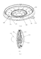
Fig.1 illustrates a schematic diagram of a shower head of a first embodiment of the present invention. -
Fig.2 illustrates a first schematic and exploded diagram of the shower head of the first embodiment of the present invention. -
Fig.3 illustrates a second schematic and exploded diagram of the shower head of the first embodiment of the present invention. -
Fig.4 illustrates a first schematic diagram of a water diversion body of the first embodiment of the present invention. -
Fig. 5 illustrates a second schematic diagram of the water diversion body of the first embodiment of the present invention. -
Fig.6 illustrates a schematic diagram of a top cover of the first embodiment of the present invention. -
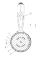
Fig.7 illustrates a sectional view of B-B section of the first embodiment of the present invention. -
Fig.8 illustrates a sectional view of C-C section of the first embodiment of the present invention. -
Fig.9 illustrates a sectional view of A-A section of the first embodiment of the present invention. -
Fig 10 illustrates a left view of the shower head of the first embodiment of the present invention. -
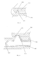
Fig.11 illustrates a sectional view of D-D section offig. 10 , when the shower head is locked and assembled. -
Fig. 12 illustrates a sectional view of D-D section offig.10 , when the shower head is disassembled. -
Fig. 13 illustrates the structure of a lock catch of a second embodiment of the present invention. -
Fig.14 illustrates the structure of a lock catch of a third embodiment of the present invention. -
Fig. 15 illustrates a schematic and exploded diagram of a fourth embodiment of the present invention. -
Fig. 16 illustrates a sectional view of B-B section of the fourth embodiment of the present invention. -
Fig.17 illustrates a sectional view of A-A section of the fourth embodiment of the present invention. - The first embodiment: please refer to
figs 1-12 , a shower head with a detachable top cover comprises amain body unit 100 with aninlet waterway 700 connected to the water resource, awater diversion body 200 rotatably disposed inside themain body unit 100 and atop cover 300. - The
main body unit 100 comprises amain body 120, which is comprises a head portion and a handle portion of one step shaping, the bottom surface of the head portion is concaved with acavity 121, one end of theinlet waterway 700 is disposed at the end of the handle portion, and is connected to a water resource pipe by ajoint 130, the other end is connected to thecavity 121. The center of the bottom of thecavity 121 is disposed with amiddle shaft 110. To ensure the sealing performance, afixed base 160 is fixed inside thecavity 121, thefixed base 160 and thewater diversion body 200 cooperate and form a close cavity connected to theinlet waterway 700, and thewater diversion body 200 and thefixed base 160 are rotatably assembled together in a sealing way. - The
water diversion body 200 is rotatably assembled inside thecavity 121 of themain body unit 100. in this embodiment, thewater diversion body 200 is disposed with a throughouthole 260, which is coupled to rotatably sleeve on themiddle shaft 100 in sealing way, with aspacer 140 and ascrew 150, thewater diversion body 200 is rotatably assembled inside thecavity 121 of themain body unit 100. This embodiment is applied with spacer and screw, but not limited to this, as needed, other structures, like ring groove and projection lock, are available. In this embodiment, thewater diversion body 200 comprises awater diversion component 230 and anouter ring 210 fixed outside thewater diversion component 230, theouter ring 210 is disposed with a protruding portion out protruding out of thewater diversion component 230 axially, the protruding portion of theouter ring 210 is disposed with aninternal revolution surface 213, the internal revolution surface is disposed with anassembly groove 214, theassembly groove 214 comprises an in-outgroove 211 connected to the external end face of theouter ring 210 and alateral groove 212 extending laterally from the internal port of the in-outgroove 211, theassembly groove 214 is L shaped. Preferred, thewater diversion component 230 is further disposed with aninner ring 220, theouter ring 210 and theinner ring 220 are spaced arranged concentrically and fixed outside thewater diversion component 230, theouter ring 210 and theinner ring 220 are axially extending out of thewater diversion component 230, an annular space is formed between theinner ring 220 and theouter ring 210. - The
top cover 300 comprises a cover piece and anouter wall 303 fixed outside the cover piece, theouter wall 303 is disposed with an extending portion extending out of the cover piece, theexternal revolution surface 301 of the extending portion is protruded with aprojection base 310, theprojection base 310 is coupled to theassembly groove 214, so that theprojection base 310 is available to pass through the in-out groove into the lateral groove, so that theprojection base 310 is available to separate from theassembly groove 214 from the lateral groove to the in-out groove. The outer wall is coupled to a clearance between theouter ring 210 and theinner ring 220. Preferred, thetop cover 300 is disposed with ashifting button 330. - In addition, a detachable
lock catch component 500 is disposed between theouter ring 210 of thewater diversion body 200 and thetop cover 300 to limit the relative rotation therebetween, so that theprojection base 310 is kept in the lateral groove when it is entered to the lateral groove from the in-out groove, thus thewater diversion body 200 is fixed to thetop cover 300 in sealing way, after thelock catch component 500 is released, rotating thetop cover 300 so that theproject base 310 can enter to the in-out groove from the lateral groove, then separate from theassembly groove 214 through the in-out groove. - In this embodiment, the internal revolution surface of the
outer ring 210 is protruded with at least a pair ofprojects 240, alock groove 241 is formed between the twoprojects 240; the outside of thetop cover 300 is protruded with alock base 320, thelock base 320 and thelock groove 241 cooperate to form the detachablelock catch component 500. In this embodiment, theouter ring 210 is disposed with at least a pair offirst breaches 251, the part of theouter ring 210 between the pair offirst breaches 251 forms a first floatingpiece 250; oneproject 2401 is disposed in the first floatingpiece 250 near to the internal side of thefirst breach 251, theother project 2402 is disposed in the remaining part of theouter ring 210 near to the internal side of thefirst breach 251. - In this embodiment, as the project is disposed in the first floating
piece 250, the first floatingpiece 250 is elastic, thus making alock catch component 500 with strong elasticity between thelock groove 241 and thelock base 320. But as needed, it can be designed without the first floating piece, but applied with a self deformation of a lock groove and a lock base to realize a lock catch. Preferred, thetop cover 300 is disposed with anouter wall 303, the projection base is disposed outside the outer wall; the outer wall is disposed with twosecond breaches 305, a second floatingpiece 340 is formed between the twosecond breaches 305, thelock base 320 is disposed in the second floatingpiece 340. - The
water diversion body 200 and thetop cover 300 are assembled together in sealing way and form a plurality ofoutlet cavities 600 corresponding to a plurality of outlet functions, thewater diversion body 200 and themain body unit 100 relatively rotate so that the plurality ofoutlet cavities 600 are switched to connect to theinlet waterway 700. In this embodiment, the switching is applied with such structure: thewater diversion component 230 is disposed with a plurality of diversion holes connected to the outlet cavity, the diversion water holes are corresponding to the inlet waterway, when thewater diversion component 230 and thetop cover 300 rotate with respect to themain body unit 100, the diversion water holes are switched to connect to the inlet waterway, the switching can be applied with existing technology, so that it is not further described here, but not limited to this kind of switching, other rotation switching methods are available. - As needed, it is preferred to disposed guiding in the projection base or project of the top cover for convenience to assemble and disassemble, please refer to
fig. 10 andfig. 11 , thelock base 320 is disposed between two projects, thelock base 320 is dis-rotatable in the limit of the twoprojects 240, thelock catch component 500 is in lock, so that the projection base is kept in the end of the lateral groove and the top cover and the water diversion body are fixed together in sealing way. To disassemble, please refer tofig.10 andfig.12 , turn in clockwise direction, thelock base 320 works on oneproject 240 to make it deformed, so that thelock base 320 separates from the two projects, resulting in thelock catch component 500 released, so that the projection base is available inside the in-out groove, and it can separate from the assembly groove through the in-out groove. Thelock base 320 and thelock groove 241 cooperate to form the detachable lock catch component. - In this embodiment, the
outer ring 210 is disposed with at least a pair offirst breaches 251, the part of theouter ring 210 between the pair offirst breaches 251 forms a first floatingpiece 250, oneproject 240 is disposed in the internal side of the first floatingpiece 250, the other side is disposed in the remainingpart 252 of theouter ring 210 corresponding to the first breachs251. - The second embodiment, as figured in
fig.12 , the difference of this embodiment from the first embodiment is thelock catch component 500. in the second embodiment, theinternal revolution surface 213 of theouter ring 210 is concaved with alock groove 241; the outside of thetop cover 300 is disposed with alock base 320, thelock base 320 and thelock groove 241 cooperate to form the detachablelock catch component 500. - The
top cover 300 is disposed with anouter wall 303, theprojection base 310 is disposed outside theouter wall 303; theouter wall 303 is disposed with twosecond breaches 305, a second floatingpiece 340 is formed between the twosecond breaches 305, thelock base 320 is disposed in the second floating piece 340 (as figured infig.2 ). - The third embodiment, as figured in
fig. 13 , the difference of this embodiment from the first embodiment is thelock catch component 500. in the shower head of the third embodiment, theinternal revolution surface 213 of theouter ring 210 is concaved with alock groove 241; the outside of thetop cover 300 is protruded with anelastic clamp spring 400, theelastic clamp spring 400 and thelock groove 241 cooperate to form the detachablelock catch component 500. - The
top cover 300 is disposed with anouter wall 303, theouter wall 303 is disposed with twosecond breaches 305, a second floatingpiece 340 is formed between the twosecond breaches 305, the second floatingpiece 340 is disposed with a T-shape groove 342, theelastic clamp spring 400 is disposed inside the T-shape groove 342, thelock end 410 thereof extends out of the T-shape groove. - The fourth embodiment, as figured in
figs 14-16 , the difference of this embodiment from the first embodiment is that, in this embodiment, the shower head has single outlet function, it comprises amain body unit 100 with aninlet waterway 700 connected to a water resource, a fixedbase 800 and atop cover 300, the fixedbase 800 is fixed inside themain body unit 100 byscrews 150, a sealingring 900 is disposed between the fixedbase 800 and themain body unit 100. - The fixed
base 800 is disposed with anouter ring 210, theouter ring 210 is disposed with aninternal revolution surface 213, theinternal revolution surface 213 is disposed with anassembly groove 214, theassembly groove 214 comprises an in-outgroove 211 leading to the external end face of theouter ring 210 and alateral groove 212 laterally extending from the internal port of the in-outgroove 211, thetop cover 300 is disposed with anexternal revolution surface 301, theexternal revolution surface 301 is protruded with aprojection base 310, theprojection base 310 is coupled to theassembly groove 214, so that theprojection base 310 is available to pass through the in-outgroove 211 into thelateral groove 212, so that theprojection base 310 is available to separate from theassembly groove 214 from thelateral groove 212 into the in-out groove 211 (refer tofig.4 and fig.5 ); - A detachable
lock catch component 500 is disposed between theouter ring 210 of the fixedbase 800 and thetop cover 300 to limit the relative rotation therebetween;
the fixedbase 800 and thetop cover 300 are assembled together in sealing way and form anoutlet cavity 600. - The
internal revolution surface 213 of theouter ring 210 is disposed with alock groove 241, theprojection base 310 and thelock groove 241 cooperate to form the detachablelock groove component 500. - This embodiment can be applied with a lock catch component like the second embodiment or the third embodiment.
- Although the present invention has been described with reference to the preferred embodiments thereof for carrying out the patent for invention, it is apparent to those skilled in the art that a variety of modifications and changes may be made without departing from the scope of the patent for invention which is intended to be defined by the appended claims.
- The present invention is provided with a shower head with a detachable top cover, a detachable lock catch component is disposed between the outer wall of the water diversion body (or a fixed base) and the top cover to limit the relative rotation thereof, the top cover of the shower head is convenient to assemble and disassemble, it is convenient to use, thus having a well industrial applicability.
Claims (15)
- A shower head with a detachable top cover, comprising a main body unit (100) with an inlet waterway (700) connected to a water resource, a water diversion body (200) rotatably assembled inside the main body unit (100) and a top cover (300), wherein:the water diversion body (200) is disposed with an outer ring (210), the outer ring (210) is disposed with an internal revolution surface (213), the internal revolution surface (213) is disposed with an assembly groove (214), the assembly groove (214) comprises an in-out groove (211) leading to the external end face of the outer ring (210) and a lateral groove (212) laterally extending from the internal port of the in-out groove (211), the top cover (300) is disposed with an external revolution surface (301), the external revolution surface (301) is protruded with a projection base (310), the projection base (310) is coupled to the assembly groove (214), so that the projection base (310) is available to pass through the in-out groove (211) into the lateral groove (212), so that the projection base (310) is available to separate from the assembly groove (214) from the lateral groove (212) into the in-out groove (211);a detachable lock catch component (500) is disposed between the outer ring (210) of the water diversion body (200) and the top cover (300) to limit the relative rotation therebetween;the water diversion body (200) and the top cover (300) are assembled together in sealing way and form a plurality of outlet cavities (600) corresponding to different outlet functions, the water diversion body (200) and the main body unit (100) relatively rotate so that the plurality of outlet cavities (600) are switched to connect to the inlet waterway (700).
- The shower head with a detachable top cover according to claim 1, wherein the internal revolution surface (213) of the outer ring (210) is protruded with at least a pair of projects (240), a lock groove (241) is formed between the two projects (240); the outside of the top cover is protruded with a lock base (320), the lock base (320) and the lock groove (241) cooperate to form the detachable lock catch component (500).
- The shower head with a detachable top cover according to claim 2, wherein the outer ring (210) is disposed with at least a pair of first breaches (251), the part of the outer ring (210) between the pair of first breaches (251) forms a first floating piece (250); one project (2401) is disposed in the first floating piece (250) near to the internal side of the first breach (251), the other project (2402) is disposed in the remaining part of the outer ring (210) near to the internal side of the first breach (251).
- The shower head with a detachable top cover according to claim 1, claim 2 or claim 3, wherein the water diversion body (200) is further disposed with an inner ring (220) and a water diversion component (230), the outer ring (210) and the inner ring (220) are concentrically disposed with internal and are concentrically fixed outside the water diversion component (230), the outer ring (210) and the inner ring (220) extend out of the water diversion component (230) axially.
- The shower head with a detachable top cover according to claim 4, wherein the water diversion component (230) is disposed with a plurality of diversion water holes (231) respectively connected to the outlet cavities, the diversion water holes (231) are corresponding to the inlet waterway (700).
- The shower head with a detachable top cover according to claim 4, wherein the top cover (300) is disposed with an outer wall (303), the outer wall (303) is coupled to a clearance between the outer ring (210) and the inner ring (220).
- The shower head with a detachable top cover according to claim 1, claim 2 or claim 3, wherein the main body unit (100) is disposed with a middle shaft (110), the water diversion body (200) is disposed with a throughout hole (260), the throughout hole (260) is coupled to rotatably sleeve on the middle shaft (110) in sealing way.
- The shower head with a detachable top cover according to claim 1, claim 2 or claim 3, wherein the main body unit (100) comprises with a main body (120), the main body (120) is disposed with a concave cavity (121), the water diversion body (200) is rotatably assembled inside the concave cavity (121).
- The shower head with a detachable top cover according to claim 2 or claim 3, wherein the top cover (300) is disposed with an outer wall (303), the projection base (310) is disposed outside the outer wall (303); the outer wall (303) is disposed with two second breaches (305), a second floating piece (340) is formed between the two second breaches (305), the lock base (320) is disposed in the second floating piece (340).
- The shower head with a detachable top cover according to claim 1, wherein the internal revolution surface (213) of the outer ring (210) is concaved with a lock groove (241); the outside of the top cover (300) is disposed with a lock base (320), the lock base (320) and the lock groove (241) cooperate to form the detachable lock catch component (500).
- The shower head with a detachable top cover according to claim 10, wherein the top cover (300) is disposed with an outer wall (303), the projection base (310) is disposed outside the outer wall (303); the outer wall (303) is disposed with two second breaches (305), a second floating piece (340) is formed between the two second breaches (305), the lock base (320) is disposed in the second floating piece (340).
- The shower head with a detachable top cover according to claim 1, wherein the internal revolution surface (213) of the outer ring (210) is concaved with a lock groove (241); the outside of the top cover (300) is protruded with an elastic clamp spring (400), the elastic clamp spring (400) and the lock groove (241) cooperate to form the detachable lock catch component (500).
- The shower head with a detachable top cover according to claim 12, wherein the top cover (300) is disposed with an outer wall (303), the outer wall (303) is disposed with two second breaches (305), a second floating piece (340) is formed between the two second breaches (305), the second floating piece (340) is disposed with a T-shape groove (342), the elastic clamp spring (400) is disposed inside the T-shape groove (342), the lock end (410) thereof extends out of the T-shape groove.
- A shower head with a detachable top cover, comprising a main body unit (100) with an inlet waterway (700) connected to a water resource, a fixed base (800) connected to the main body unit (100) and a top cover (300), wherein:the fixed base (800) is disposed with an outer ring (210), the outer ring (210) is disposed with an internal revolution surface (213), the internal revolution surface (213) is disposed with an assembly groove (214), the assembly groove (214) comprises an in-out groove (211) leading to the external end face of the outer ring (210) and a lateral groove (212) laterally extending from the internal port of the in-out groove (211), the top cover (300) is disposed with an external revolution surface (301), the external revolution surface (301) is protruded with a projection base (310), the projection base (310) is coupled to the assembly groove (214), so that the projection base (310) is available to pass through the in-out groove (211) into the lateral groove (212), so that the projection base (310) is available to separate from the assembly groove (214) from the lateral groove (212) into the in-out groove (211);a detachable lock catch component (500) is disposed between the outer ring (210) of the fixed base (800) and the top cover (300) to limit the relative rotation therebetween;the fixed base (800) and the top cover (300) are assembled together in sealing way and form an outlet cavity (600).
- The shower head with a detachable top cove according to claim 14, wherein the internal revolution surface (213) of the outer ring (210) is disposed with a lock groove (241), the projection base (310) and the lock groove (241) cooperate to form the detachable lock groove component (500).
Applications Claiming Priority (3)
| Application Number | Priority Date | Filing Date | Title |
|---|---|---|---|
| CN 201220044280 CN202516711U (en) | 2012-02-10 | 2012-02-10 | Detachable surface cover shower head |
| CN201210031170.7A CN103240198B (en) | 2012-02-10 | 2012-02-10 | Can dismountable cover gondola water faucet |
| PCT/CN2013/071447 WO2013117160A1 (en) | 2012-02-10 | 2013-02-06 | Showerhead with detachable top cover |
Publications (3)
| Publication Number | Publication Date |
|---|---|
| EP2813292A1 true EP2813292A1 (en) | 2014-12-17 |
| EP2813292A4 EP2813292A4 (en) | 2015-10-21 |
| EP2813292B1 EP2813292B1 (en) | 2019-01-16 |
Family
ID=48946914
Family Applications (1)
| Application Number | Title | Priority Date | Filing Date |
|---|---|---|---|
| EP13747198.3A Not-in-force EP2813292B1 (en) | 2012-02-10 | 2013-02-06 | Showerhead with detachable top cover |
Country Status (2)
| Country | Link |
|---|---|
| EP (1) | EP2813292B1 (en) |
| WO (1) | WO2013117160A1 (en) |
Cited By (2)
| Publication number | Priority date | Publication date | Assignee | Title |
|---|---|---|---|---|
| EP3248689A1 (en) * | 2016-05-23 | 2017-11-29 | Globe Union Industrial Corp. | Spray head |
| JP2018154980A (en) * | 2017-03-16 | 2018-10-04 | 株式会社タカギ | Faucet equipment |
Families Citing this family (4)
| Publication number | Priority date | Publication date | Assignee | Title |
|---|---|---|---|---|
| CN202951581U (en) * | 2012-12-04 | 2013-05-29 | 恺霖卫浴科技(厦门)有限公司 | Shower head with detachable surface cover |
| CN110772114B (en) * | 2018-07-30 | 2024-12-13 | 武汉苏泊尔炊具有限公司 | Pot cover, cooking utensil and pressure cooker including the pot cover |
| CN109909082A (en) * | 2019-03-01 | 2019-06-21 | 厦门建霖健康家居股份有限公司 | A quick detachable shower device |
| CN115597144B (en) * | 2022-10-10 | 2025-10-28 | 安徽美博智能科技有限公司 | An accessory for a detachable protective clothing cooling interface |
Family Cites Families (9)
| Publication number | Priority date | Publication date | Assignee | Title |
|---|---|---|---|---|
| GB2311474B (en) * | 1996-03-27 | 1999-10-13 | Caradon Mira Ltd | Improvements in or relating to shower fitttings |
| US6715699B1 (en) * | 1999-04-08 | 2004-04-06 | Masco Corporation | Showerhead engine assembly |
| CN2552605Y (en) * | 2002-03-28 | 2003-05-28 | 林夏斌 | Dismounting spraying-cap shower nozzle |
| DE10307073B4 (en) * | 2003-02-19 | 2009-05-07 | Grohe Ag | shower |
| US7766260B2 (en) * | 2008-02-12 | 2010-08-03 | Wen-Yi Lin | Showerhead |
| CN201168657Y (en) * | 2008-03-16 | 2008-12-24 | 周汉琴 | Fast dismounting and easy-to-clean showerhead |
| CN102527528B (en) * | 2010-12-31 | 2014-03-12 | 厦门松霖科技有限公司 | Dismounting device for sprinkler |
| CN102527556A (en) * | 2012-01-19 | 2012-07-04 | 厦门松霖科技有限公司 | Shower head with demountable surface lid |
| CN202516711U (en) * | 2012-02-10 | 2012-11-07 | 厦门松霖科技有限公司 | Detachable surface cover shower head |
-
2013
- 2013-02-06 WO PCT/CN2013/071447 patent/WO2013117160A1/en not_active Ceased
- 2013-02-06 EP EP13747198.3A patent/EP2813292B1/en not_active Not-in-force
Cited By (2)
| Publication number | Priority date | Publication date | Assignee | Title |
|---|---|---|---|---|
| EP3248689A1 (en) * | 2016-05-23 | 2017-11-29 | Globe Union Industrial Corp. | Spray head |
| JP2018154980A (en) * | 2017-03-16 | 2018-10-04 | 株式会社タカギ | Faucet equipment |
Also Published As
| Publication number | Publication date |
|---|---|
| EP2813292B1 (en) | 2019-01-16 |
| WO2013117160A1 (en) | 2013-08-15 |
| EP2813292A4 (en) | 2015-10-21 |
Similar Documents
| Publication | Publication Date | Title |
|---|---|---|
| US10449558B2 (en) | Handheld pet spray wand | |
| US8790511B2 (en) | Water filtering device | |
| US9470334B2 (en) | Flow adjusting device with a button | |
| EP3053655B1 (en) | A multifunctional shower head | |
| US8607662B2 (en) | Wall-mounted faucet control components | |
| EP2813292B1 (en) | Showerhead with detachable top cover | |
| US10322420B2 (en) | Pressing waterway switch device and shower head | |
| GB2563951A (en) | Flow control component and shower | |
| US11369981B2 (en) | Water outflow control assembly, shower head and shower head assembly method | |
| US10781578B2 (en) | Water separator with shower seat | |
| US9175780B2 (en) | Button switch three-way valve | |
| US8739831B2 (en) | Self-reset valve | |
| US9238236B2 (en) | Waterway switch valve set and a shower head using same | |
| CN202516711U (en) | Detachable surface cover shower head | |
| CN102527556A (en) | Shower head with demountable surface lid | |
| US20130062439A1 (en) | Seesaw control shower | |
| CN104148202A (en) | Detachable shower head | |
| US9573142B2 (en) | Handle rotating switch shower head | |
| EP2848314B1 (en) | Valve group switched by push button and shower head using the valve group | |
| CN113145332B (en) | Water outlet device | |
| US9446419B2 (en) | Rotary switch outlet mechanism | |
| CN217463290U (en) | Faucet with simplified structure | |
| CN201866326U (en) | Straight-through switching valve | |
| US20190143359A1 (en) | Sound producing member adapted to press at any angle, press-switching water discharging mechanism and shower head | |
| CN213039880U (en) | Faucet handle mounting structure and double-handle conjoined faucet thereof |
Legal Events
| Date | Code | Title | Description |
|---|---|---|---|
| PUAI | Public reference made under article 153(3) epc to a published international application that has entered the european phase |
Free format text: ORIGINAL CODE: 0009012 |
|
| 17P | Request for examination filed |
Effective date: 20140910 |
|
| AK | Designated contracting states |
Kind code of ref document: A1 Designated state(s): AL AT BE BG CH CY CZ DE DK EE ES FI FR GB GR HR HU IE IS IT LI LT LU LV MC MK MT NL NO PL PT RO RS SE SI SK SM TR |
|
| AX | Request for extension of the european patent |
Extension state: BA ME |
|
| DAX | Request for extension of the european patent (deleted) | ||
| RA4 | Supplementary search report drawn up and despatched (corrected) |
Effective date: 20150918 |
|
| RIC1 | Information provided on ipc code assigned before grant |
Ipc: B05B 1/12 20060101ALI20150914BHEP Ipc: B05B 1/16 20060101AFI20150914BHEP Ipc: B05B 15/02 20060101ALN20150914BHEP Ipc: B05B 15/06 20060101ALI20150914BHEP Ipc: B05B 1/18 20060101ALI20150914BHEP |
|
| RIN1 | Information on inventor provided before grant (corrected) |
Inventor name: LUO, SHUIYUAN Inventor name: ZHOU, HUASONG Inventor name: CAO, YONGBIN Inventor name: CAO, BIN |
|
| 17Q | First examination report despatched |
Effective date: 20161013 |
|
| STAA | Information on the status of an ep patent application or granted ep patent |
Free format text: STATUS: EXAMINATION IS IN PROGRESS |
|
| RAP1 | Party data changed (applicant data changed or rights of an application transferred) |
Owner name: XIAMEN SOLEX HIGH-TECH INDUSTRIES CO., LTD. Owner name: ZHOU, HUASONG |
|
| RAP1 | Party data changed (applicant data changed or rights of an application transferred) |
Owner name: XIAMEN SOLEX HIGH-TECH INDUSTRIES CO., LTD. |
|
| RAP1 | Party data changed (applicant data changed or rights of an application transferred) |
Owner name: XIAMEN SOLEX HIGH-TECH INDUSTRIES CO., LTD. |
|
| RIC1 | Information provided on ipc code assigned before grant |
Ipc: B05B 1/18 20060101ALI20180517BHEP Ipc: B05B 15/60 20180101ALI20180517BHEP Ipc: B05B 1/12 20060101ALI20180517BHEP Ipc: B05B 1/16 20060101AFI20180517BHEP |
|
| GRAP | Despatch of communication of intention to grant a patent |
Free format text: ORIGINAL CODE: EPIDOSNIGR1 |
|
| STAA | Information on the status of an ep patent application or granted ep patent |
Free format text: STATUS: GRANT OF PATENT IS INTENDED |
|
| INTG | Intention to grant announced |
Effective date: 20180622 |
|
| GRAS | Grant fee paid |
Free format text: ORIGINAL CODE: EPIDOSNIGR3 |
|
| GRAA | (expected) grant |
Free format text: ORIGINAL CODE: 0009210 |
|
| STAA | Information on the status of an ep patent application or granted ep patent |
Free format text: STATUS: THE PATENT HAS BEEN GRANTED |
|
| AK | Designated contracting states |
Kind code of ref document: B1 Designated state(s): AL AT BE BG CH CY CZ DE DK EE ES FI FR GB GR HR HU IE IS IT LI LT LU LV MC MK MT NL NO PL PT RO RS SE SI SK SM TR |
|
| REG | Reference to a national code |
Ref country code: GB Ref legal event code: FG4D |
|
| REG | Reference to a national code |
Ref country code: CH Ref legal event code: EP |
|
| REG | Reference to a national code |
Ref country code: IE Ref legal event code: FG4D |
|
| REG | Reference to a national code |
Ref country code: DE Ref legal event code: R096 Ref document number: 602013049898 Country of ref document: DE |
|
| REG | Reference to a national code |
Ref country code: AT Ref legal event code: REF Ref document number: 1089291 Country of ref document: AT Kind code of ref document: T Effective date: 20190215 |
|
| REG | Reference to a national code |
Ref country code: NL Ref legal event code: MP Effective date: 20190116 |
|
| REG | Reference to a national code |
Ref country code: LT Ref legal event code: MG4D |
|
| PG25 | Lapsed in a contracting state [announced via postgrant information from national office to epo] |
Ref country code: NL Free format text: LAPSE BECAUSE OF FAILURE TO SUBMIT A TRANSLATION OF THE DESCRIPTION OR TO PAY THE FEE WITHIN THE PRESCRIBED TIME-LIMIT Effective date: 20190116 |
|
| REG | Reference to a national code |
Ref country code: AT Ref legal event code: MK05 Ref document number: 1089291 Country of ref document: AT Kind code of ref document: T Effective date: 20190116 |
|
| PG25 | Lapsed in a contracting state [announced via postgrant information from national office to epo] |
Ref country code: ES Free format text: LAPSE BECAUSE OF FAILURE TO SUBMIT A TRANSLATION OF THE DESCRIPTION OR TO PAY THE FEE WITHIN THE PRESCRIBED TIME-LIMIT Effective date: 20190116 Ref country code: PL Free format text: LAPSE BECAUSE OF FAILURE TO SUBMIT A TRANSLATION OF THE DESCRIPTION OR TO PAY THE FEE WITHIN THE PRESCRIBED TIME-LIMIT Effective date: 20190116 Ref country code: LT Free format text: LAPSE BECAUSE OF FAILURE TO SUBMIT A TRANSLATION OF THE DESCRIPTION OR TO PAY THE FEE WITHIN THE PRESCRIBED TIME-LIMIT Effective date: 20190116 Ref country code: FI Free format text: LAPSE BECAUSE OF FAILURE TO SUBMIT A TRANSLATION OF THE DESCRIPTION OR TO PAY THE FEE WITHIN THE PRESCRIBED TIME-LIMIT Effective date: 20190116 Ref country code: NO Free format text: LAPSE BECAUSE OF FAILURE TO SUBMIT A TRANSLATION OF THE DESCRIPTION OR TO PAY THE FEE WITHIN THE PRESCRIBED TIME-LIMIT Effective date: 20190416 Ref country code: PT Free format text: LAPSE BECAUSE OF FAILURE TO SUBMIT A TRANSLATION OF THE DESCRIPTION OR TO PAY THE FEE WITHIN THE PRESCRIBED TIME-LIMIT Effective date: 20190516 Ref country code: SE Free format text: LAPSE BECAUSE OF FAILURE TO SUBMIT A TRANSLATION OF THE DESCRIPTION OR TO PAY THE FEE WITHIN THE PRESCRIBED TIME-LIMIT Effective date: 20190116 |
|
| PG25 | Lapsed in a contracting state [announced via postgrant information from national office to epo] |
Ref country code: GR Free format text: LAPSE BECAUSE OF FAILURE TO SUBMIT A TRANSLATION OF THE DESCRIPTION OR TO PAY THE FEE WITHIN THE PRESCRIBED TIME-LIMIT Effective date: 20190417 Ref country code: BG Free format text: LAPSE BECAUSE OF FAILURE TO SUBMIT A TRANSLATION OF THE DESCRIPTION OR TO PAY THE FEE WITHIN THE PRESCRIBED TIME-LIMIT Effective date: 20190416 Ref country code: HR Free format text: LAPSE BECAUSE OF FAILURE TO SUBMIT A TRANSLATION OF THE DESCRIPTION OR TO PAY THE FEE WITHIN THE PRESCRIBED TIME-LIMIT Effective date: 20190116 Ref country code: IS Free format text: LAPSE BECAUSE OF FAILURE TO SUBMIT A TRANSLATION OF THE DESCRIPTION OR TO PAY THE FEE WITHIN THE PRESCRIBED TIME-LIMIT Effective date: 20190516 Ref country code: LV Free format text: LAPSE BECAUSE OF FAILURE TO SUBMIT A TRANSLATION OF THE DESCRIPTION OR TO PAY THE FEE WITHIN THE PRESCRIBED TIME-LIMIT Effective date: 20190116 Ref country code: RS Free format text: LAPSE BECAUSE OF FAILURE TO SUBMIT A TRANSLATION OF THE DESCRIPTION OR TO PAY THE FEE WITHIN THE PRESCRIBED TIME-LIMIT Effective date: 20190116 |
|
| REG | Reference to a national code |
Ref country code: CH Ref legal event code: PL |
|
| REG | Reference to a national code |
Ref country code: DE Ref legal event code: R097 Ref document number: 602013049898 Country of ref document: DE |
|
| PG25 | Lapsed in a contracting state [announced via postgrant information from national office to epo] |
Ref country code: RO Free format text: LAPSE BECAUSE OF FAILURE TO SUBMIT A TRANSLATION OF THE DESCRIPTION OR TO PAY THE FEE WITHIN THE PRESCRIBED TIME-LIMIT Effective date: 20190116 Ref country code: SK Free format text: LAPSE BECAUSE OF FAILURE TO SUBMIT A TRANSLATION OF THE DESCRIPTION OR TO PAY THE FEE WITHIN THE PRESCRIBED TIME-LIMIT Effective date: 20190116 Ref country code: CZ Free format text: LAPSE BECAUSE OF FAILURE TO SUBMIT A TRANSLATION OF THE DESCRIPTION OR TO PAY THE FEE WITHIN THE PRESCRIBED TIME-LIMIT Effective date: 20190116 Ref country code: LU Free format text: LAPSE BECAUSE OF NON-PAYMENT OF DUE FEES Effective date: 20190206 Ref country code: MC Free format text: LAPSE BECAUSE OF FAILURE TO SUBMIT A TRANSLATION OF THE DESCRIPTION OR TO PAY THE FEE WITHIN THE PRESCRIBED TIME-LIMIT Effective date: 20190116 Ref country code: AL Free format text: LAPSE BECAUSE OF FAILURE TO SUBMIT A TRANSLATION OF THE DESCRIPTION OR TO PAY THE FEE WITHIN THE PRESCRIBED TIME-LIMIT Effective date: 20190116 Ref country code: EE Free format text: LAPSE BECAUSE OF FAILURE TO SUBMIT A TRANSLATION OF THE DESCRIPTION OR TO PAY THE FEE WITHIN THE PRESCRIBED TIME-LIMIT Effective date: 20190116 Ref country code: IT Free format text: LAPSE BECAUSE OF FAILURE TO SUBMIT A TRANSLATION OF THE DESCRIPTION OR TO PAY THE FEE WITHIN THE PRESCRIBED TIME-LIMIT Effective date: 20190116 Ref country code: AT Free format text: LAPSE BECAUSE OF FAILURE TO SUBMIT A TRANSLATION OF THE DESCRIPTION OR TO PAY THE FEE WITHIN THE PRESCRIBED TIME-LIMIT Effective date: 20190116 Ref country code: DK Free format text: LAPSE BECAUSE OF FAILURE TO SUBMIT A TRANSLATION OF THE DESCRIPTION OR TO PAY THE FEE WITHIN THE PRESCRIBED TIME-LIMIT Effective date: 20190116 |
|
| REG | Reference to a national code |
Ref country code: BE Ref legal event code: MM Effective date: 20190228 |
|
| PLBE | No opposition filed within time limit |
Free format text: ORIGINAL CODE: 0009261 |
|
| STAA | Information on the status of an ep patent application or granted ep patent |
Free format text: STATUS: NO OPPOSITION FILED WITHIN TIME LIMIT |
|
| REG | Reference to a national code |
Ref country code: IE Ref legal event code: MM4A |
|
| PG25 | Lapsed in a contracting state [announced via postgrant information from national office to epo] |
Ref country code: SM Free format text: LAPSE BECAUSE OF FAILURE TO SUBMIT A TRANSLATION OF THE DESCRIPTION OR TO PAY THE FEE WITHIN THE PRESCRIBED TIME-LIMIT Effective date: 20190116 |
|
| 26N | No opposition filed |
Effective date: 20191017 |
|
| PG25 | Lapsed in a contracting state [announced via postgrant information from national office to epo] |
Ref country code: CH Free format text: LAPSE BECAUSE OF NON-PAYMENT OF DUE FEES Effective date: 20190228 Ref country code: LI Free format text: LAPSE BECAUSE OF NON-PAYMENT OF DUE FEES Effective date: 20190228 |
|
| PG25 | Lapsed in a contracting state [announced via postgrant information from national office to epo] |
Ref country code: IE Free format text: LAPSE BECAUSE OF NON-PAYMENT OF DUE FEES Effective date: 20190206 |
|
| PG25 | Lapsed in a contracting state [announced via postgrant information from national office to epo] |
Ref country code: BE Free format text: LAPSE BECAUSE OF NON-PAYMENT OF DUE FEES Effective date: 20190228 Ref country code: SI Free format text: LAPSE BECAUSE OF FAILURE TO SUBMIT A TRANSLATION OF THE DESCRIPTION OR TO PAY THE FEE WITHIN THE PRESCRIBED TIME-LIMIT Effective date: 20190116 |
|
| PG25 | Lapsed in a contracting state [announced via postgrant information from national office to epo] |
Ref country code: TR Free format text: LAPSE BECAUSE OF FAILURE TO SUBMIT A TRANSLATION OF THE DESCRIPTION OR TO PAY THE FEE WITHIN THE PRESCRIBED TIME-LIMIT Effective date: 20190116 |
|
| PG25 | Lapsed in a contracting state [announced via postgrant information from national office to epo] |
Ref country code: MT Free format text: LAPSE BECAUSE OF NON-PAYMENT OF DUE FEES Effective date: 20190206 |
|
| PG25 | Lapsed in a contracting state [announced via postgrant information from national office to epo] |
Ref country code: CY Free format text: LAPSE BECAUSE OF FAILURE TO SUBMIT A TRANSLATION OF THE DESCRIPTION OR TO PAY THE FEE WITHIN THE PRESCRIBED TIME-LIMIT Effective date: 20190116 |
|
| PG25 | Lapsed in a contracting state [announced via postgrant information from national office to epo] |
Ref country code: HU Free format text: LAPSE BECAUSE OF FAILURE TO SUBMIT A TRANSLATION OF THE DESCRIPTION OR TO PAY THE FEE WITHIN THE PRESCRIBED TIME-LIMIT; INVALID AB INITIO Effective date: 20130206 |
|
| PG25 | Lapsed in a contracting state [announced via postgrant information from national office to epo] |
Ref country code: MK Free format text: LAPSE BECAUSE OF FAILURE TO SUBMIT A TRANSLATION OF THE DESCRIPTION OR TO PAY THE FEE WITHIN THE PRESCRIBED TIME-LIMIT Effective date: 20190116 |
|
| PGFP | Annual fee paid to national office [announced via postgrant information from national office to epo] |
Ref country code: FR Payment date: 20230217 Year of fee payment: 11 |
|
| PGFP | Annual fee paid to national office [announced via postgrant information from national office to epo] |
Ref country code: GB Payment date: 20230221 Year of fee payment: 11 Ref country code: DE Payment date: 20221222 Year of fee payment: 11 |
|
| REG | Reference to a national code |
Ref country code: DE Ref legal event code: R119 Ref document number: 602013049898 Country of ref document: DE |
|
| GBPC | Gb: european patent ceased through non-payment of renewal fee |
Effective date: 20240206 |
|
| PG25 | Lapsed in a contracting state [announced via postgrant information from national office to epo] |
Ref country code: DE Free format text: LAPSE BECAUSE OF NON-PAYMENT OF DUE FEES Effective date: 20240903 |
|
| PG25 | Lapsed in a contracting state [announced via postgrant information from national office to epo] |
Ref country code: GB Free format text: LAPSE BECAUSE OF NON-PAYMENT OF DUE FEES Effective date: 20240206 |
|
| PG25 | Lapsed in a contracting state [announced via postgrant information from national office to epo] |
Ref country code: FR Free format text: LAPSE BECAUSE OF NON-PAYMENT OF DUE FEES Effective date: 20240229 |
|
| PG25 | Lapsed in a contracting state [announced via postgrant information from national office to epo] |
Ref country code: GB Free format text: LAPSE BECAUSE OF NON-PAYMENT OF DUE FEES Effective date: 20240206 Ref country code: FR Free format text: LAPSE BECAUSE OF NON-PAYMENT OF DUE FEES Effective date: 20240229 Ref country code: DE Free format text: LAPSE BECAUSE OF NON-PAYMENT OF DUE FEES Effective date: 20240903 |