EP2812889B1 - Systeme et procede de surveillance de portail par detection des entrees et sorties - Google Patents
Systeme et procede de surveillance de portail par detection des entrees et sorties Download PDFInfo
- Publication number
- EP2812889B1 EP2812889B1 EP13701698.6A EP13701698A EP2812889B1 EP 2812889 B1 EP2812889 B1 EP 2812889B1 EP 13701698 A EP13701698 A EP 13701698A EP 2812889 B1 EP2812889 B1 EP 2812889B1
- Authority
- EP
- European Patent Office
- Prior art keywords
- portal
- area
- scene
- video
- foreground objects
- Prior art date
- Legal status (The legal status is an assumption and is not a legal conclusion. Google has not performed a legal analysis and makes no representation as to the accuracy of the status listed.)
- Active
Links
- 238000000034 method Methods 0.000 title claims description 20
- 238000012544 monitoring process Methods 0.000 title claims description 20
- 239000013598 vector Substances 0.000 claims description 10
- 238000010586 diagram Methods 0.000 description 8
- 230000009471 action Effects 0.000 description 4
- 230000000875 corresponding effect Effects 0.000 description 4
- 230000008569 process Effects 0.000 description 4
- 230000008859 change Effects 0.000 description 3
- 230000000694 effects Effects 0.000 description 2
- 238000013459 approach Methods 0.000 description 1
- 238000010276 construction Methods 0.000 description 1
- 230000002596 correlated effect Effects 0.000 description 1
- 230000003993 interaction Effects 0.000 description 1
- 230000004044 response Effects 0.000 description 1
- 230000011218 segmentation Effects 0.000 description 1
- 230000001960 triggered effect Effects 0.000 description 1
Images


Classifications
-
- H—ELECTRICITY
- H04—ELECTRIC COMMUNICATION TECHNIQUE
- H04N—PICTORIAL COMMUNICATION, e.g. TELEVISION
- H04N7/00—Television systems
- H04N7/18—Closed-circuit television [CCTV] systems, i.e. systems in which the video signal is not broadcast
- H04N7/188—Capturing isolated or intermittent images triggered by the occurrence of a predetermined event, e.g. an object reaching a predetermined position
-
- G—PHYSICS
- G08—SIGNALLING
- G08B—SIGNALLING OR CALLING SYSTEMS; ORDER TELEGRAPHS; ALARM SYSTEMS
- G08B13/00—Burglar, theft or intruder alarms
- G08B13/18—Actuation by interference with heat, light, or radiation of shorter wavelength; Actuation by intruding sources of heat, light, or radiation of shorter wavelength
- G08B13/189—Actuation by interference with heat, light, or radiation of shorter wavelength; Actuation by intruding sources of heat, light, or radiation of shorter wavelength using passive radiation detection systems
- G08B13/194—Actuation by interference with heat, light, or radiation of shorter wavelength; Actuation by intruding sources of heat, light, or radiation of shorter wavelength using passive radiation detection systems using image scanning and comparing systems
- G08B13/196—Actuation by interference with heat, light, or radiation of shorter wavelength; Actuation by intruding sources of heat, light, or radiation of shorter wavelength using passive radiation detection systems using image scanning and comparing systems using television cameras
- G08B13/19602—Image analysis to detect motion of the intruder, e.g. by frame subtraction
Definitions
- Video systems used for surveillance are becoming increasingly common. They can be used to monitor buildings and rooms within buildings. The video systems can also be used monitor public areas such as parks or public spaces in and around buildings. In some cases they are used to catch illegal activity. In other cases, they are used to monitor usage such as shopping patterns in a retail store or traffic levels on public roadways, or detect events that would require the intervention of emergency response personnel.
- the video systems can further store metadata with the video data generated by the cameras so that operators can later search through the mountains of video data for events of interest in the archived video data. Examples of events of interest can include individuals entering a secure entryway or the theft of equipment or goods. Other uses are monitoring buildings and rooms within buildings to enable energy savings when building spaces are not being utilized.
- tripwires The specific technique for determining whether or not tripwires have been crossed relies on an assumption that the tripwires that are created on the screen are assumed to be at ground level in the displayed two-dimensional image. The top and bottom portions of foreground objects are then monitored to determine whether or not the bottoms of the objects overlap with the tripwire. When this occurs, these tripwire events are recorded.
- Such video analytic systems provide capabilities such as logging when people or other objects cross the tripwire. Often such systems will maintain statistics concerning the probability the individual in fact crossed the tripwire, and the systems may even take and send a snapshot of the video when such an event is detected.
- US5969755 A discloses a method to provide automatic content-based video indexing from object motion, in which moving objects in video from a surveillance camera are detected in the video sequence using motion segmentation methods and then tracked by an object tracker.
- the present invention concerns a video analytics system that can detect subjects when they are entering and/or exiting from an area being monitored, such as a room.
- the system enables a user to define a portal, such as doorway of the area being monitored, e.g., room.
- the system then monitors the movement of foreground objects in the area being monitored. Objects that appear only in the portal are classified as passing by the portal, e.g., doorway. Objects that initially appear in the portal and then are detected moving within the area being monitored are classified as having entered the area being monitored via the portal. Objects that are in the area being monitored and then disappear within the portal are classified as having exited the area being monitored via the portal.
- the system further has provisions for generating real-time alerts and performing forensic searches.
- the portal is defined and a video analysis system initially determines the background of a camera view and then proceeds to monitor foreground objects. It determines whether foreground objects have entered or exited the area being monitored and then generates alerts to the user.
- system can provide the user with a forensic search capability in which the portal is defined and then previously captured video is searched to determine whether or not foreground objects had previously entered or exited the area being monitored via the portal.
- the invention features a method for monitoring a portal of an area being monitored with a video analysis system.
- the method comprises enabling definition of a portal area of a background model of a scene as a portal, the portal area being a rectangular or other two dimensional area surrounded and within a remainder of the scene, and then monitoring movement of foreground objects against the background model.
- Foreground objects which, when they first appear within the scene, first appear within the portal area of the scene and then move out of the portal area and remain in the scene, are classified as entering the area being monitored via the portal.
- the system enables the definition of the portal area by an operator using a graphical user interface to identify the portal within the scene.
- the definition of the portal area is performed automatically by the system by analyzing video data to identify portals through which foreground objects enter and exit area being monitored.
- movement of the foreground objects is tracked between frames of the video data and vectors generated indicating movement of the foreground objects.
- This information is preferably stored as metadata.
- the foreground objects When the foreground objects first appear within the portal area and then disappear within the portal area, they are preferably classified as passing by the portal. Corresponding metadata are generated but the objects are not classified as having entered the area being monitored unless they appear in the scene but outside the area of the portal.
- the invention features method for monitoring a portal of an area being monitored with a video analysis system.
- This method also comprises enabling definition of a portal area of a background model of a scene as a portal, the portal area being a rectangular or other two dimensional area surrounded and within a remainder of the scene, and then monitoring movement of foreground objects against the background model.
- Foreground objects are classified as exiting the area being monitored when they are present in the scene but outside the portal area and then pass into the portal area and then disappear from the scene within the portal area.
- the invention can be characterized as a video monitoring and analysis system.
- This system comprises at least one video camera generating video data of a scene of an area being monitored and a video data and metadata archive that stores the video data from the at least one video camera.
- a video analysis system receives video data from the at least one video camera and analyzes the video data. It provides for the definition of a portal area of a background model of the scene of an area being monitored as a portal, the portal area being a rectangular or other two dimensional area surrounded and within a remainder of the scene, and then monitors movement of foreground objects against the background model. Metadata are generated and stored with the video data indicating that the foreground objects have entered the area being monitored when the foreground objects first appear within the scene within the portal area and then move out of the portal area and remain in the scene.
- the invention can be characterized as a video monitoring and analysis system.
- This system comprises at least one video camera generating video data of a scene of an area being monitored and a video data and metadata archive that stores the video data from the at least one video camera.
- a video analysis system receives video data from the at least one video camera and analyzes the video data. It provides for the definition of a portal area of a background model of the scene of an area being monitored as a portal, the portal area being a rectangular or other two dimensional area surrounded and within a remainder of the scene, and then monitors movement of foreground objects against the background model. Metadata are generated and stored with the video data indicating that the foreground objects have exited the area being monitored when the foreground objects are present in the scene but outside the portal area and then pass into the portal area and then disappear from the scene while in the portal area.
- the system then further provides for real-time alerts and forensic searches.
- real-time alerts can be generated based upon or triggered by individuals entering or leaving the area being monitored, such as a room being monitored by the system.
- the system enables later forensic searches to identify when individuals entered or left the area being monitored. Further, the corresponding video data are accessed to allow the operator to identify those individuals and possibly take further action.
- Figs. 1A , B, and C illustrate the architecture of video recording and analysis systems 100 to which the present invention is relevant.
- the video recording and analysis system 100 generally comprises a number of video cameras 110.
- the current system can handle and process the video data feeds from up to 128 separate video cameras 110.
- the network 104 can be a private network, such as the local area network provided in a building. In other embodiments, the network 104 can include a combination of private networks and even public networks so that the video feeds from the video cameras 110 can be transmitted to the network video recorder system 112 enabling the recording and analysis of video in remote locations.
- the network video recorder 112 stores the video data and any metadata in a video data and metadata archive 114.
- this data archive 114 includes both a video store 116 that includes the raw video data from the cameras 110 and a metadata store 118 that includes metadata that are generated for the associated video.
- the video data generated by the cameras 110 is analyzed by an analysis system 115.
- This analysis system generates the metadata from the video data, which metadata are stored in the metadata store 118 in the video data and metadata archive 114.
- the analysis system 115 is implemented with the network video recorder 112.
- the video data from the video cameras 110 are received over the network 104 at the video recorder 112.
- the analysis system 115 can be either a process that runs on the network video recorder 112 or a separate system that is deployed on an interface to the network video recorder system 112.
- the analysis system 115 is part of each of separate video cameras 110.
- the metadata are generated locally at each of the video cameras 110.
- the video data with the metadata are then transmitted over the network 104 to the network video recorder 112, which then stores the video data and the metadata in the archive 114.
- Fig. 1C illustrates still another example.
- the analysis system 115 is a separate system that processes video data preferably by accessing the video data in the video data and metadata archive 114.
- the video data generated by each of the cameras 110 is stored to the archive 114 by the network video recorder 112. Then, the analysis system 115 accesses that video data from the archive 114 generates the metadata and then stores the metadata back into the metadata store 118 of the archive 114.
- all of the video data generated by the video cameras 110 are stored in the video store 116.
- video data are only stored when the analysis system 115, upon analyzing that video, decides that an event of interest, for example, has occurred and that the video should then be stored.
- the video data stored in the video store 116 and the associated metadata stored in the metadata store 118 is correlated to each other via timestamps stored with the metadata that correlate to the video data from the particular video camera 110 and the event detected in the video data that gave rise to the metadata 118.
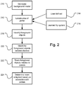
- Fig. 2 illustrates how the video data from each of the video cameras 110 is analyzed by the analysis system 115.
- the network video analysis system 112 first analyzes the video data from each of the video cameras 110 to generate a background model for the scenes that are being observed by each of the video cameras of the respective areas being monitored.
- the background model represents the stationary portion of the scene that is being monitored by each video camera. This is the portion of the scene that does not change from frame to frame.
- Each pixel in the captured scene is averaged over time in order to generate an image of the scene, for example a room, that contains only the portions of the scene that do not change or change only very slowly.
- any portals for example doorways, in the scene from the area being monitored are identified in step 212.
- portals are identified by an operator in step 214 that observes the scene and then using a graphical user interface of the analysis system 115 identifies a two dimensional area within the scene's two dimensional image that represents a portal. This is an area of the scene through which objects, such as individuals, can enter and leave the area being monitored, such as a room.
- the analysis system 115 automatically identifies these portals in step 216. This is accomplished by analyzing the video data from the scene over time to determine regions in the scene that represent portals through which individuals or other objects can enter or leave the area being monitored.
- the analysis system 115 monitors successive frames of the video data from each of the cameras to identify foreground objects. Foreground objects are identified by comparing the current video data to the background model. Generally, foreground objects are regions of the scene where it differs from the background model, although in some instances, if these foreground objects are stationary for long periods in the video data, then they will become part of the background model and lose their status as a foreground object.
- the video data are then analyzed between successive frames in step 220. This is performed in order to track how the foreground objects move within the scene. In this way, individuals can be tracked over time as they move within the scene.
- the foreground objects are identified with bounding boxes and stored as metadata as they move within a scene.
- Vectors characterizing the movement of the foreground objects through the scene are preferably further stored with the video data as metadata.
- these foreground objects are further tracked relative to portals, such as doorways, in the area being monitored. In this way, their interaction with portals is used to determine whether or not the foreground objects, e.g., individuals, have entered or left the area being monitored, for example.
- portals such as doorways
- metadata is further stored with the video data as these foreground objects enter and leave the scene so that their movements are recorded and are accessed for later analysis.
- alerts are generated in real time so that alerts can be generated to security personnel, for example, in the case where an unauthorized individual has entered a secure area being monitored by the video cameras 110.
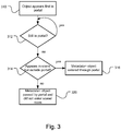
- Fig. 3 illustrates how the analysis system 115 determines that a foreground object, such as an individual, has entered the scene being monitored, a room for example.
- step 310 the analysis system 115 monitors the scene and specifically the video data from the video cameras 110 for foreground objects that first appear in the portal, such as a doorway.
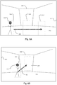
- the scene 512 is contained in the video data from a video camera 110 that is located in an area being monitored, such as a room.
- a portal or doorway 516 is defined.
- this portal 516 is a generally rectangle or other two dimensional area of the scene 512.
- An individual 510 constitutes a foreground object.
- the analysis system 115 tracks this individual by drawing a bounding box 514 around the individual. In this example, the foreground object box 514 has first appeared within the area of the portal 516.
- the analysis system 115 monitors the foreground object 514 to determine whether or not it has stayed within the portal 516. So long as it stays entirely within the portal, the analysis system 115 continues to track the foreground object 514 but does not conclude that it has entered the area being monitored, such as the room.
- step 3144 it also checks to determine whether the foreground object 514 appears in the scene but outside the portal 516.
- FIG. 4B This scenario is illustrated in Fig. 4B .
- the foreground object 514 in one frame moves to position 514' in a subsequent frame.
- the analysis system 115 monitors the movement of this foreground object 514 between these frames and generates a vector 520 that represents the movement of the foreground object 514, in this example the individual 510, between successive frames and over time. If the individual continues on this path indicated by vector 520, then it will pass out of the scene, but did not enter the area being monitored. In this way, the metadata generated by the analysis system 115 and stored in the metadata store 118 in association with this video data will simply be that an individual passed by portal 516.
- the analysis system concludes that the foreground object has merely passed-by the portal and has not entered the area being monitored.
- This situation is illustrated in Fig. 4C showing the foreground object 514"continuing to pass by the portal 516 such that part of the individual's body 510 is obscured by the portal 516, on one hand, yet no part of the individual's body 510 is ever outside the area if portal 516, on the other.
- the analysis system 115 when the analysis system 115 concludes that the foreground object 514 has disappeared within the portal 516, then the analysis system 115 generates metadata for this video data that a foreground object has passed by the portal in step 320.
- the analysis system 115 also monitors whether the foreground object 514 appears within the scene but outside the portal. This scenario is illustrated in Fig. 4A . In an earlier frame, the individual is identified as foreground object 514. But then in a later frame, the foreground object is determined to be at position 514'. The analysis system 115 generates a vector 520 and stores this vector with the metadata of the video data to represent the movement of the foreground object 514 between successive frames and thus its movement over time.
- This movement in the illustrated example, is further recorded as a foreground object 514 or individual 510 as entering the area being monitored.
- the foreground object is first identified within the portal 516 and then located in this scene but outside the portal at a later point in time, see 514' of Fig. 4A . It is thus determined to have entered the monitored area via this portal.
- the analysis system 115 generates metadata in conjunction with the video data in step 316 to note that the foreground object 514 has entered the room.
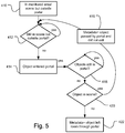
- Fig. 5 illustrates the process by which the analysis system 115 concludes that a foreground object, such as an individual, has left the area of interest, such as a room 512.
- the analysis system 115 tracks foreground objects 514 that are within the room 512 but not entirely within the portal 516. These foreground objects are recorded and metadata are stored to the video data and metadata archive 114 to indicate that the foreground objects, such as individuals, are currently within the room 512 in step 412. As the foreground objects move within the room, their position is tracked and corresponding vectors indicating their movement are stored as metadata to the metadata store 118.
- Fig. 6A This is illustrated in Fig. 6A .
- the foreground object moves from position 514 to 514' to 514" over time.
- the vector 520 is generated and stored as metadata to indicate the foreground object's movement within the room 512.
- the foreground objects are also monitored to determine whether they enter the area of the portal 516, in step 414.
- the analysis system 115 determines that they have entered the portal in step 414, the analysis system 115 then monitors the foreground objects to determine whether they stay within the portal 516, or not, in step 418.
- the objects 514 are determined to have entered the area of the portal, see 514', then to have left the area of the portal, see 514", but are still detected within the scene as determined in step 420.
- metadata are generated in step 416 that the foreground object passed by the portal 516.
- FIG. 6B The situation in which the foreground object disappears within the portal 516 is illustrated in Fig. 6B .
- the foreground object 514 moves from the room to the area of the portal as indicated by position 514'. In this position, the foreground object 514' is within the portal 516.
- the analysis system 115 concludes that the individual 510 has left the room 512 via the portal 516.
- step 422 metadata are generated indicating that the foreground object 514 left the area of interest via the portal and this metadata are stored to the metadata store 118 along with the corresponding video, which is stored in the video store 116.
Landscapes
- Engineering & Computer Science (AREA)
- Multimedia (AREA)
- Signal Processing (AREA)
- Closed-Circuit Television Systems (AREA)
- Image Analysis (AREA)
Claims (14)
- Procédé de surveillance d'un portail d'une zone surveillée avec un système d'analyse vidéo comprenant :l'activation de la définition d'une zone de portail d'un modèle d'arrière-plan d'une scène en tant que portail, la zone de portail étant une zone rectangulaire ou une autre zone bidimensionnelle entourée et située dans un reste de la scène ;la surveillance du mouvement des objets d'avant-plan par rapport au modèle d'arrière-plan ; etle classement des objets de premier plan qui, lorsqu'ils apparaissent pour la première fois dans la scène, apparaissent dans la zone du portail de la scène, puis sortent de la zone du portail et restent dans la scène comme entrant dans la zone surveillée.
- Procédé de surveillance d'un portail d'une zone surveillée à l'aide d'un système d'analyse vidéo, comprenant :l'activation de la définition d'une zone de portail d'un modèle d'arrière-plan d'une scène en tant que portail ;la surveillance du mouvement des objets d'avant-plan par rapport au modèle d'arrière-plan, la zone du portail étant une zone rectangulaire ou une autre zone bidimensionnelle entourée et située dans le reste de la scène ; etle classement des objets de premier plan présents dans la scène mais en dehors de la zone du portail, qui passent ensuite dans la zone du portail et disparaissent ensuite de la scène à l'intérieur de la zone du portail, comme sortant de la zone surveillée.
- Procédé selon la revendication 1 ou 2, l'activation de la définition de la zone de portail comprenant un opérateur utilisant une interface utilisateur graphique pour identifier le portail à l'intérieur de la scène.
- Procédé selon la revendication 1 ou 2, l'activation de la définition de la zone du portail comprenant l'analyse de données vidéo pour identifier des portails par lesquels les objets de premier plan entrent et sortent de la zone surveillée.
- Procédé selon la revendication 1 ou 2, la surveillance du mouvement des objets d'avant-plan comprenant le suivi des objets d'avant-plan entre les images des données vidéo et la génération de vecteurs indiquant le mouvement des objets d'avant-plan.
- Procédé selon la revendication 1 ou 2, comprenant en outre le classement des objets d'avant-plan qui passent dans la zone du portail et ensuite hors de la zone du portail mais restent dans la scène comme se déplaçant dans la zone surveillée.
- Procédé selon la revendication 1 ou 2, comprenant en outre le classement des objets d'avant-plan qui apparaissent d'abord dans la zone du portail et qui disparaissent ensuite dans la zone du portail en passant par le portail.
- Système de surveillance et d'analyse vidéo comprenant :au moins une caméra vidéo générant des données vidéo d'une scène d'une zone surveillée ;une archive de données vidéo et de métadonnées qui stocke les données vidéo provenant de la ou des caméras vidéo ; etun système d'analyse vidéo qui reçoit des données vidéo de l'au moins une caméra vidéo et analyse les données vidéo, le système d'analyse vidéo activant la définition d'une zone de portail d'un modèle d'arrière-plan de la scène comme un portail, la zone de portail étant une zone rectangulaire ou une autre zone bidimensionnelle entourée et située dans un reste de la scène, puis la surveillance de mouvement des objets d'avant-plan par rapport au modèle d'arrière-plan, et la génération et le stockage de métadonnées dans les archives de données et de métadonnées vidéo indiquant que les objets d'avant-plan sont entrés dans la zone surveillée lorsque les objets d'avant-plan apparaissent pour la première fois dans la scène à l'intérieur de la zone de portail, puis qu'ils sortent de la zone de portail et restent dans la scène.
- Système de surveillance et d'analyse vidéo comprenant :au moins une caméra vidéo générant des données vidéo d'une scène d'une zone surveillée ;une archive de données vidéo et de métadonnées qui stocke les données vidéo provenant de l'au moins une caméra vidéo ; etun système d'analyse vidéo qui reçoit des données vidéo de l'au moins une caméra vidéo et les analyse, le système d'analyse vidéo activant la définition d'une zone de portail d'un modèle d'arrière-plan de la scène comme un portail, la zone de portail étant une zone rectangulaire ou une autre zone bidimensionnelle entourée et située dans un reste de la scène, puis la surveillance du mouvement des objets d'avant-plan par rapport au modèle d'arrière-plan, et la génération et le stockage de métadonnées dans les archives de données vidéo et de métadonnées indiquant que les objets d'avant-plan ont quitté la zone surveillée lorsque les objets d'avant-plan sont présents dans la scène mais en dehors de la zone de portail, puis passent dans la zone de portail et disparaissent ensuite de la scène lorsqu'ils sont dans la zone de portail.
- Système selon la revendication 8 ou 9, le système d'analyse vidéo activant la définition de la zone de portail par un opérateur utilisant une interface utilisateur graphique pour identifier le portail à l'intérieur de la scène.
- Système selon la revendication 8 ou 9, le système d'analyse vidéo analysant les données vidéo provenant d'au moins une caméra vidéo pour identifier les portails par lesquels les objets d'avant-plan entrent et sortent de la zone surveillée.
- Système selon la revendication 8 ou 9, le système d'analyse vidéo suivant les objets d'avant-plan entre les images des données vidéo et générant des vecteurs indiquant le mouvement des objets d'avant-plan dans la scène.
- Système selon la revendication 8 ou 9, le système d'analyse vidéo classant les objets d'avant-plan qui apparaissent d'abord dans la zone de portail et disparaissent ensuite dans la zone de portail comme passant par le portail.
- Système selon la revendication 13, le système d'analyse vidéo générant des métadonnées indiquant que les objets d'avant-plan sont passés par le portail.
Applications Claiming Priority (2)
| Application Number | Priority Date | Filing Date | Title |
|---|---|---|---|
| US13/367,770 US11470285B2 (en) | 2012-02-07 | 2012-02-07 | Method and system for monitoring portal to detect entry and exit |
| PCT/US2013/021742 WO2013119364A1 (fr) | 2012-02-07 | 2013-01-16 | Procédé et système de surveillance d'un portail afin de détecter une entrée et une sortie |
Publications (2)
| Publication Number | Publication Date |
|---|---|
| EP2812889A1 EP2812889A1 (fr) | 2014-12-17 |
| EP2812889B1 true EP2812889B1 (fr) | 2020-11-25 |
Family
ID=47624426
Family Applications (1)
| Application Number | Title | Priority Date | Filing Date |
|---|---|---|---|
| EP13701698.6A Active EP2812889B1 (fr) | 2012-02-07 | 2013-01-16 | Systeme et procede de surveillance de portail par detection des entrees et sorties |
Country Status (3)
| Country | Link |
|---|---|
| US (1) | US11470285B2 (fr) |
| EP (1) | EP2812889B1 (fr) |
| WO (1) | WO2013119364A1 (fr) |
Families Citing this family (5)
| Publication number | Priority date | Publication date | Assignee | Title |
|---|---|---|---|---|
| US10645345B2 (en) * | 2012-07-03 | 2020-05-05 | Verint Americas Inc. | System and method of video capture and search optimization |
| US10217120B1 (en) | 2015-04-21 | 2019-02-26 | Videomining Corporation | Method and system for in-store shopper behavior analysis with multi-modal sensor fusion |
| CN106027931B (zh) * | 2016-04-14 | 2018-03-16 | 平安科技(深圳)有限公司 | 视频录制方法及服务器 |
| JP7250440B2 (ja) * | 2018-05-31 | 2023-04-03 | キヤノン株式会社 | 撮影装置、情報処理装置、情報処理方法、およびプログラム |
| JP7342606B2 (ja) * | 2019-10-23 | 2023-09-12 | 日本電気株式会社 | 情報処理装置、アクセス制御方法及びアクセス制御プログラム |
Family Cites Families (23)
| Publication number | Priority date | Publication date | Assignee | Title |
|---|---|---|---|---|
| US5969755A (en) * | 1996-02-05 | 1999-10-19 | Texas Instruments Incorporated | Motion based event detection system and method |
| US8564661B2 (en) * | 2000-10-24 | 2013-10-22 | Objectvideo, Inc. | Video analytic rule detection system and method |
| US6441734B1 (en) | 2000-12-12 | 2002-08-27 | Koninklijke Philips Electronics N.V. | Intruder detection through trajectory analysis in monitoring and surveillance systems |
| US6625310B2 (en) | 2001-03-23 | 2003-09-23 | Diamondback Vision, Inc. | Video segmentation using statistical pixel modeling |
| US7424175B2 (en) | 2001-03-23 | 2008-09-09 | Objectvideo, Inc. | Video segmentation using statistical pixel modeling |
| US6696945B1 (en) * | 2001-10-09 | 2004-02-24 | Diamondback Vision, Inc. | Video tripwire |
| US6970083B2 (en) | 2001-10-09 | 2005-11-29 | Objectvideo, Inc. | Video tripwire |
| WO2004045215A1 (fr) * | 2002-11-12 | 2004-05-27 | Intellivid Corporation | Procede et systeme pour la localisation et la surveillance de comportement d'objets multiples se deplaçant a travers une pluralite de champ de vision |
| US7280673B2 (en) | 2003-10-10 | 2007-10-09 | Intellivid Corporation | System and method for searching for changes in surveillance video |
| US7148912B2 (en) | 2003-11-17 | 2006-12-12 | Vidient Systems, Inc. | Video surveillance system in which trajectory hypothesis spawning allows for trajectory splitting and/or merging |
| US20050104959A1 (en) | 2003-11-17 | 2005-05-19 | Mei Han | Video surveillance system with trajectory hypothesis scoring based on at least one non-spatial parameter |
| US7127083B2 (en) | 2003-11-17 | 2006-10-24 | Vidient Systems, Inc. | Video surveillance system with object detection and probability scoring based on object class |
| US7088846B2 (en) | 2003-11-17 | 2006-08-08 | Vidient Systems, Inc. | Video surveillance system that detects predefined behaviors based on predetermined patterns of movement through zones |
| US7136507B2 (en) | 2003-11-17 | 2006-11-14 | Vidient Systems, Inc. | Video surveillance system with rule-based reasoning and multiple-hypothesis scoring |
| US7646401B2 (en) | 2004-01-30 | 2010-01-12 | ObjectVideo, Inc | Video-based passback event detection |
| US7613324B2 (en) | 2005-06-24 | 2009-11-03 | ObjectVideo, Inc | Detection of change in posture in video |
| GB0709329D0 (en) * | 2007-05-15 | 2007-06-20 | Ipsotek Ltd | Data processing apparatus |
| US8401229B2 (en) | 2007-09-04 | 2013-03-19 | Objectvideo, Inc. | Stationary target detection by exploiting changes in background model |
| JP5004845B2 (ja) * | 2008-03-26 | 2012-08-22 | キヤノン株式会社 | 監視端末装置およびその表示処理方法,プログラム,メモリ |
| US8358834B2 (en) * | 2009-08-18 | 2013-01-22 | Behavioral Recognition Systems | Background model for complex and dynamic scenes |
| US8218819B2 (en) * | 2009-09-01 | 2012-07-10 | Behavioral Recognition Systems, Inc. | Foreground object detection in a video surveillance system |
| AU2009251048B2 (en) * | 2009-12-18 | 2013-12-19 | Canon Kabushiki Kaisha | Background image and mask estimation for accurate shift-estimation for video object detection in presence of misalignment |
| US8743205B2 (en) * | 2011-08-10 | 2014-06-03 | Nice Systems Ltd. | System and method for semantic video content analysis |
-
2012
- 2012-02-07 US US13/367,770 patent/US11470285B2/en active Active
-
2013
- 2013-01-16 EP EP13701698.6A patent/EP2812889B1/fr active Active
- 2013-01-16 WO PCT/US2013/021742 patent/WO2013119364A1/fr active Application Filing
Non-Patent Citations (1)
| Title |
|---|
| None * |
Also Published As
| Publication number | Publication date |
|---|---|
| US20130201338A1 (en) | 2013-08-08 |
| EP2812889A1 (fr) | 2014-12-17 |
| WO2013119364A1 (fr) | 2013-08-15 |
| US11470285B2 (en) | 2022-10-11 |
Similar Documents
| Publication | Publication Date | Title |
|---|---|---|
| Elharrouss et al. | A review of video surveillance systems | |
| CA2541437C (fr) | Systeme et procede de recherche de changements dans une video de surveillance | |
| US7646401B2 (en) | Video-based passback event detection | |
| CA2545535C (fr) | Fil declencheur video | |
| US10019877B2 (en) | Apparatus and methods for the semi-automatic tracking and examining of an object or an event in a monitored site | |
| CA2601477C (fr) | Selection de cameras et suivi d'objets intelligents | |
| EP2966852B1 (fr) | Procédé, dispositif, et système de vidéo surveillance | |
| US20080074496A1 (en) | Video analytics for banking business process monitoring | |
| Trivedi et al. | Distributed interactive video arrays for event capture and enhanced situational awareness | |
| US20050157169A1 (en) | Object blocking zones to reduce false alarms in video surveillance systems | |
| EP2812889B1 (fr) | Systeme et procede de surveillance de portail par detection des entrees et sorties | |
| KR20070101401A (ko) | 비디오 프리미티브를 사용하는 비디오 감시 시스템 | |
| Alshammari et al. | Intelligent multi-camera video surveillance system for smart city applications | |
| Zabłocki et al. | Intelligent video surveillance systems for public spaces–a survey | |
| KR101964683B1 (ko) | 스마트 영상처리장치 및 그 장치의 구동방법 | |
| KR101019384B1 (ko) | 전방위 카메라 및 팬/틸트/줌 카메라를 이용한 무인 감시 장치 및 방법 | |
| CN104980653A (zh) | 视频监控系统中的照相机参数更新的系统和方法 | |
| CA2460426A1 (fr) | Fil-piege video | |
| Fuentes et al. | Tracking-based event detection for CCTV systems | |
| US20220366575A1 (en) | Method and system for gathering information of an object moving in an area of interest | |
| Davies et al. | A progress review of intelligent CCTV surveillance systems | |
| US20180211113A1 (en) | System and method for detecting potential drive-up drug deal activity via trajectory-based analysis | |
| Valera et al. | A review of the state-of-the-art in distributed surveillance systems | |
| KR101516672B1 (ko) | 스마터 비디오 컨트롤 센터를 활용하는 영상 감지 방법 및 이를 이용한 영상 감지 시스템 | |
| Monari et al. | A knowledge-based camera selection approach for object tracking in large sensor networks |
Legal Events
| Date | Code | Title | Description |
|---|---|---|---|
| PUAI | Public reference made under article 153(3) epc to a published international application that has entered the european phase |
Free format text: ORIGINAL CODE: 0009012 |
|
| 17P | Request for examination filed |
Effective date: 20140729 |
|
| AK | Designated contracting states |
Kind code of ref document: A1 Designated state(s): AL AT BE BG CH CY CZ DE DK EE ES FI FR GB GR HR HU IE IS IT LI LT LU LV MC MK MT NL NO PL PT RO RS SE SI SK SM TR |
|
| AX | Request for extension of the european patent |
Extension state: BA ME |
|
| RIN1 | Information on inventor provided before grant (corrected) |
Inventor name: BUEHLER, CHRISTOPHER J. Inventor name: WESTMACOTT, IAN |
|
| DAX | Request for extension of the european patent (deleted) | ||
| STAA | Information on the status of an ep patent application or granted ep patent |
Free format text: STATUS: EXAMINATION IS IN PROGRESS |
|
| 17Q | First examination report despatched |
Effective date: 20170622 |
|
| GRAP | Despatch of communication of intention to grant a patent |
Free format text: ORIGINAL CODE: EPIDOSNIGR1 |
|
| STAA | Information on the status of an ep patent application or granted ep patent |
Free format text: STATUS: GRANT OF PATENT IS INTENDED |
|
| INTG | Intention to grant announced |
Effective date: 20200619 |
|
| GRAS | Grant fee paid |
Free format text: ORIGINAL CODE: EPIDOSNIGR3 |
|
| GRAA | (expected) grant |
Free format text: ORIGINAL CODE: 0009210 |
|
| STAA | Information on the status of an ep patent application or granted ep patent |
Free format text: STATUS: THE PATENT HAS BEEN GRANTED |
|
| AK | Designated contracting states |
Kind code of ref document: B1 Designated state(s): AL AT BE BG CH CY CZ DE DK EE ES FI FR GB GR HR HU IE IS IT LI LT LU LV MC MK MT NL NO PL PT RO RS SE SI SK SM TR |
|
| REG | Reference to a national code |
Ref country code: GB Ref legal event code: FG4D |
|
| REG | Reference to a national code |
Ref country code: CH Ref legal event code: EP |
|
| REG | Reference to a national code |
Ref country code: AT Ref legal event code: REF Ref document number: 1339188 Country of ref document: AT Kind code of ref document: T Effective date: 20201215 |
|
| REG | Reference to a national code |
Ref country code: DE Ref legal event code: R096 Ref document number: 602013074272 Country of ref document: DE |
|
| REG | Reference to a national code |
Ref country code: IE Ref legal event code: FG4D |
|
| REG | Reference to a national code |
Ref country code: AT Ref legal event code: MK05 Ref document number: 1339188 Country of ref document: AT Kind code of ref document: T Effective date: 20201125 |
|
| REG | Reference to a national code |
Ref country code: NL Ref legal event code: MP Effective date: 20201125 |
|
| PG25 | Lapsed in a contracting state [announced via postgrant information from national office to epo] |
Ref country code: FI Free format text: LAPSE BECAUSE OF FAILURE TO SUBMIT A TRANSLATION OF THE DESCRIPTION OR TO PAY THE FEE WITHIN THE PRESCRIBED TIME-LIMIT Effective date: 20201125 Ref country code: RS Free format text: LAPSE BECAUSE OF FAILURE TO SUBMIT A TRANSLATION OF THE DESCRIPTION OR TO PAY THE FEE WITHIN THE PRESCRIBED TIME-LIMIT Effective date: 20201125 Ref country code: PT Free format text: LAPSE BECAUSE OF FAILURE TO SUBMIT A TRANSLATION OF THE DESCRIPTION OR TO PAY THE FEE WITHIN THE PRESCRIBED TIME-LIMIT Effective date: 20210325 Ref country code: NO Free format text: LAPSE BECAUSE OF FAILURE TO SUBMIT A TRANSLATION OF THE DESCRIPTION OR TO PAY THE FEE WITHIN THE PRESCRIBED TIME-LIMIT Effective date: 20210225 Ref country code: GR Free format text: LAPSE BECAUSE OF FAILURE TO SUBMIT A TRANSLATION OF THE DESCRIPTION OR TO PAY THE FEE WITHIN THE PRESCRIBED TIME-LIMIT Effective date: 20210226 |
|
| PG25 | Lapsed in a contracting state [announced via postgrant information from national office to epo] |
Ref country code: IS Free format text: LAPSE BECAUSE OF FAILURE TO SUBMIT A TRANSLATION OF THE DESCRIPTION OR TO PAY THE FEE WITHIN THE PRESCRIBED TIME-LIMIT Effective date: 20210325 Ref country code: SE Free format text: LAPSE BECAUSE OF FAILURE TO SUBMIT A TRANSLATION OF THE DESCRIPTION OR TO PAY THE FEE WITHIN THE PRESCRIBED TIME-LIMIT Effective date: 20201125 Ref country code: PL Free format text: LAPSE BECAUSE OF FAILURE TO SUBMIT A TRANSLATION OF THE DESCRIPTION OR TO PAY THE FEE WITHIN THE PRESCRIBED TIME-LIMIT Effective date: 20201125 Ref country code: LV Free format text: LAPSE BECAUSE OF FAILURE TO SUBMIT A TRANSLATION OF THE DESCRIPTION OR TO PAY THE FEE WITHIN THE PRESCRIBED TIME-LIMIT Effective date: 20201125 Ref country code: AT Free format text: LAPSE BECAUSE OF FAILURE TO SUBMIT A TRANSLATION OF THE DESCRIPTION OR TO PAY THE FEE WITHIN THE PRESCRIBED TIME-LIMIT Effective date: 20201125 Ref country code: BG Free format text: LAPSE BECAUSE OF FAILURE TO SUBMIT A TRANSLATION OF THE DESCRIPTION OR TO PAY THE FEE WITHIN THE PRESCRIBED TIME-LIMIT Effective date: 20210225 |
|
| REG | Reference to a national code |
Ref country code: LT Ref legal event code: MG9D |
|
| PG25 | Lapsed in a contracting state [announced via postgrant information from national office to epo] |
Ref country code: HR Free format text: LAPSE BECAUSE OF FAILURE TO SUBMIT A TRANSLATION OF THE DESCRIPTION OR TO PAY THE FEE WITHIN THE PRESCRIBED TIME-LIMIT Effective date: 20201125 |
|
| PG25 | Lapsed in a contracting state [announced via postgrant information from national office to epo] |
Ref country code: RO Free format text: LAPSE BECAUSE OF FAILURE TO SUBMIT A TRANSLATION OF THE DESCRIPTION OR TO PAY THE FEE WITHIN THE PRESCRIBED TIME-LIMIT Effective date: 20201125 Ref country code: SK Free format text: LAPSE BECAUSE OF FAILURE TO SUBMIT A TRANSLATION OF THE DESCRIPTION OR TO PAY THE FEE WITHIN THE PRESCRIBED TIME-LIMIT Effective date: 20201125 Ref country code: LT Free format text: LAPSE BECAUSE OF FAILURE TO SUBMIT A TRANSLATION OF THE DESCRIPTION OR TO PAY THE FEE WITHIN THE PRESCRIBED TIME-LIMIT Effective date: 20201125 Ref country code: SM Free format text: LAPSE BECAUSE OF FAILURE TO SUBMIT A TRANSLATION OF THE DESCRIPTION OR TO PAY THE FEE WITHIN THE PRESCRIBED TIME-LIMIT Effective date: 20201125 Ref country code: EE Free format text: LAPSE BECAUSE OF FAILURE TO SUBMIT A TRANSLATION OF THE DESCRIPTION OR TO PAY THE FEE WITHIN THE PRESCRIBED TIME-LIMIT Effective date: 20201125 Ref country code: CZ Free format text: LAPSE BECAUSE OF FAILURE TO SUBMIT A TRANSLATION OF THE DESCRIPTION OR TO PAY THE FEE WITHIN THE PRESCRIBED TIME-LIMIT Effective date: 20201125 |
|
| REG | Reference to a national code |
Ref country code: DE Ref legal event code: R097 Ref document number: 602013074272 Country of ref document: DE |
|
| PG25 | Lapsed in a contracting state [announced via postgrant information from national office to epo] |
Ref country code: MC Free format text: LAPSE BECAUSE OF FAILURE TO SUBMIT A TRANSLATION OF THE DESCRIPTION OR TO PAY THE FEE WITHIN THE PRESCRIBED TIME-LIMIT Effective date: 20201125 Ref country code: DK Free format text: LAPSE BECAUSE OF FAILURE TO SUBMIT A TRANSLATION OF THE DESCRIPTION OR TO PAY THE FEE WITHIN THE PRESCRIBED TIME-LIMIT Effective date: 20201125 |
|
| REG | Reference to a national code |
Ref country code: CH Ref legal event code: PL |
|
| PG25 | Lapsed in a contracting state [announced via postgrant information from national office to epo] |
Ref country code: LU Free format text: LAPSE BECAUSE OF NON-PAYMENT OF DUE FEES Effective date: 20210116 |
|
| PLBE | No opposition filed within time limit |
Free format text: ORIGINAL CODE: 0009261 |
|
| STAA | Information on the status of an ep patent application or granted ep patent |
Free format text: STATUS: NO OPPOSITION FILED WITHIN TIME LIMIT |
|
| REG | Reference to a national code |
Ref country code: BE Ref legal event code: MM Effective date: 20210131 |
|
| PG25 | Lapsed in a contracting state [announced via postgrant information from national office to epo] |
Ref country code: NL Free format text: LAPSE BECAUSE OF FAILURE TO SUBMIT A TRANSLATION OF THE DESCRIPTION OR TO PAY THE FEE WITHIN THE PRESCRIBED TIME-LIMIT Effective date: 20201125 Ref country code: IT Free format text: LAPSE BECAUSE OF FAILURE TO SUBMIT A TRANSLATION OF THE DESCRIPTION OR TO PAY THE FEE WITHIN THE PRESCRIBED TIME-LIMIT Effective date: 20201125 Ref country code: AL Free format text: LAPSE BECAUSE OF FAILURE TO SUBMIT A TRANSLATION OF THE DESCRIPTION OR TO PAY THE FEE WITHIN THE PRESCRIBED TIME-LIMIT Effective date: 20201125 |
|
| 26N | No opposition filed |
Effective date: 20210826 |
|
| PG25 | Lapsed in a contracting state [announced via postgrant information from national office to epo] |
Ref country code: SI Free format text: LAPSE BECAUSE OF FAILURE TO SUBMIT A TRANSLATION OF THE DESCRIPTION OR TO PAY THE FEE WITHIN THE PRESCRIBED TIME-LIMIT Effective date: 20201125 Ref country code: LI Free format text: LAPSE BECAUSE OF NON-PAYMENT OF DUE FEES Effective date: 20210131 Ref country code: CH Free format text: LAPSE BECAUSE OF NON-PAYMENT OF DUE FEES Effective date: 20210131 Ref country code: ES Free format text: LAPSE BECAUSE OF FAILURE TO SUBMIT A TRANSLATION OF THE DESCRIPTION OR TO PAY THE FEE WITHIN THE PRESCRIBED TIME-LIMIT Effective date: 20201125 |
|
| PG25 | Lapsed in a contracting state [announced via postgrant information from national office to epo] |
Ref country code: IE Free format text: LAPSE BECAUSE OF NON-PAYMENT OF DUE FEES Effective date: 20210116 |
|
| PG25 | Lapsed in a contracting state [announced via postgrant information from national office to epo] |
Ref country code: IS Free format text: LAPSE BECAUSE OF FAILURE TO SUBMIT A TRANSLATION OF THE DESCRIPTION OR TO PAY THE FEE WITHIN THE PRESCRIBED TIME-LIMIT Effective date: 20210325 |
|
| PG25 | Lapsed in a contracting state [announced via postgrant information from national office to epo] |
Ref country code: BE Free format text: LAPSE BECAUSE OF NON-PAYMENT OF DUE FEES Effective date: 20210131 |
|
| PG25 | Lapsed in a contracting state [announced via postgrant information from national office to epo] |
Ref country code: HU Free format text: LAPSE BECAUSE OF FAILURE TO SUBMIT A TRANSLATION OF THE DESCRIPTION OR TO PAY THE FEE WITHIN THE PRESCRIBED TIME-LIMIT; INVALID AB INITIO Effective date: 20130116 |
|
| PG25 | Lapsed in a contracting state [announced via postgrant information from national office to epo] |
Ref country code: CY Free format text: LAPSE BECAUSE OF FAILURE TO SUBMIT A TRANSLATION OF THE DESCRIPTION OR TO PAY THE FEE WITHIN THE PRESCRIBED TIME-LIMIT Effective date: 20201125 |
|
| PG25 | Lapsed in a contracting state [announced via postgrant information from national office to epo] |
Ref country code: MK Free format text: LAPSE BECAUSE OF FAILURE TO SUBMIT A TRANSLATION OF THE DESCRIPTION OR TO PAY THE FEE WITHIN THE PRESCRIBED TIME-LIMIT Effective date: 20201125 |
|
| PGFP | Annual fee paid to national office [announced via postgrant information from national office to epo] |
Ref country code: DE Payment date: 20240129 Year of fee payment: 12 Ref country code: GB Payment date: 20240123 Year of fee payment: 12 |
|
| PGFP | Annual fee paid to national office [announced via postgrant information from national office to epo] |
Ref country code: FR Payment date: 20240125 Year of fee payment: 12 |
|
| PG25 | Lapsed in a contracting state [announced via postgrant information from national office to epo] |
Ref country code: TR Free format text: LAPSE BECAUSE OF FAILURE TO SUBMIT A TRANSLATION OF THE DESCRIPTION OR TO PAY THE FEE WITHIN THE PRESCRIBED TIME-LIMIT Effective date: 20201125 |