EP2812670B1 - Method of modeling permeation of a multilayer polymer structure to solvents - Google Patents
Method of modeling permeation of a multilayer polymer structure to solvents Download PDFInfo
- Publication number
- EP2812670B1 EP2812670B1 EP13706626.2A EP13706626A EP2812670B1 EP 2812670 B1 EP2812670 B1 EP 2812670B1 EP 13706626 A EP13706626 A EP 13706626A EP 2812670 B1 EP2812670 B1 EP 2812670B1
- Authority
- EP
- European Patent Office
- Prior art keywords
- composition
- monolayer
- compounds
- solvent mixture
- multilayer structure
- Prior art date
- Legal status (The legal status is an assumption and is not a legal conclusion. Google has not performed a legal analysis and makes no representation as to the accuracy of the status listed.)
- Active
Links
Images

Classifications
-
- B—PERFORMING OPERATIONS; TRANSPORTING
- B01—PHYSICAL OR CHEMICAL PROCESSES OR APPARATUS IN GENERAL
- B01D—SEPARATION
- B01D65/00—Accessories or auxiliary operations, in general, for separation processes or apparatus using semi-permeable membranes
- B01D65/10—Testing of membranes or membrane apparatus; Detecting or repairing leaks
-
- G—PHYSICS
- G01—MEASURING; TESTING
- G01N—INVESTIGATING OR ANALYSING MATERIALS BY DETERMINING THEIR CHEMICAL OR PHYSICAL PROPERTIES
- G01N15/00—Investigating characteristics of particles; Investigating permeability, pore-volume or surface-area of porous materials
- G01N15/08—Investigating permeability, pore-volume, or surface area of porous materials
- G01N15/082—Investigating permeability by forcing a fluid through a sample
-
- B—PERFORMING OPERATIONS; TRANSPORTING
- B01—PHYSICAL OR CHEMICAL PROCESSES OR APPARATUS IN GENERAL
- B01D—SEPARATION
- B01D69/00—Semi-permeable membranes for separation processes or apparatus characterised by their form, structure or properties; Manufacturing processes specially adapted therefor
- B01D69/12—Composite membranes; Ultra-thin membranes
- B01D69/1216—Three or more layers
-
- B—PERFORMING OPERATIONS; TRANSPORTING
- B01—PHYSICAL OR CHEMICAL PROCESSES OR APPARATUS IN GENERAL
- B01D—SEPARATION
- B01D71/00—Semi-permeable membranes for separation processes or apparatus characterised by the material; Manufacturing processes specially adapted therefor
- B01D71/06—Organic material
- B01D71/26—Polyalkenes
- B01D71/261—Polyethylene
-
- B—PERFORMING OPERATIONS; TRANSPORTING
- B01—PHYSICAL OR CHEMICAL PROCESSES OR APPARATUS IN GENERAL
- B01D—SEPARATION
- B01D71/00—Semi-permeable membranes for separation processes or apparatus characterised by the material; Manufacturing processes specially adapted therefor
- B01D71/06—Organic material
- B01D71/38—Polyalkenylalcohols; Polyalkenylesters; Polyalkenylethers; Polyalkenylaldehydes; Polyalkenylketones; Polyalkenylacetals; Polyalkenylketals
-
- G—PHYSICS
- G01—MEASURING; TESTING
- G01N—INVESTIGATING OR ANALYSING MATERIALS BY DETERMINING THEIR CHEMICAL OR PHYSICAL PROPERTIES
- G01N15/00—Investigating characteristics of particles; Investigating permeability, pore-volume or surface-area of porous materials
- G01N15/08—Investigating permeability, pore-volume, or surface area of porous materials
- G01N2015/0866—Sorption
Definitions
- the present invention relates to the field of permeation to solvent mixtures of a multilayer polymeric structure.
- permeation is meant the transport of a fluid, such as a mixture of solvents, through a membrane. More specifically, it is the amount of each of the components of a solvent mixture, passing through a multilayer polymer structure.
- the invention relates to a permeation modeling method for solvent mixtures of a multilayer polymer structure, in particular for gasolines and more particularly for gasolines of the fuel type.
- the invention finally relates to a computer program implementing the modeling method.
- a container in particular a fuel tank, comprising a multilayer polymer structure whose permeation is modeled according to the modeling method, is furthermore described.
- containers or tanks used for storing or transporting chemicals were made of metal. These metal parts are gradually replaced by monolayer plastic materials, lighter, easier to implement, for making tanks with complex geometries, not sensitive to corrosion.
- these single-layer plastic tanks no longer comply with emission regulations, and plastic solutions need to be developed with greater performance in terms of barrier properties than single-layer solutions.
- One way used industrially today is the multilayer plastic structure combining different carefully chosen materials, in order to increase the barrier properties of said structure.
- the transport sector is constantly seeking to lighten vehicles, to reduce their emissions and their energy consumption.
- these lightweight materials must meet the strictest sealing standards.
- the polymer wall of a fuel tank must have good barrier properties to limit the mass transfer of fuels into the environment.
- the word barrier is used in the description to describe barrier materials to essences.
- the tank wall is formed in particular of a multilayer polymer structure, each layers acting as a barrier for at least one of the fuel compounds.
- a gasoline is a mixture of aromatic, aliphatic compounds and an oxygenated compound, very often alcohol.
- polymers are not barriers to all compounds in a gasoline and all polymers are not barriers to the same compounds in a gasoline.
- polyethylene for example, is a barrier to alcohol, but not to toluene, which is an aromatic compound constituting gasoline.
- the key materials used in the barrier structures are characterized by low levels of swelling when they are brought into contact with the species, and by reduced mobility of the small scattering molecules in the polymer matrix. This imposes very long equilibrium delays for industrial multilayer tank structures, typically of the order of the year. Moreover, the experimental study of these phenomena requires the accumulation of numerous measurements. These considerations led the applicant to perform these characterizations from much thinner films than those implemented in the tank walls. Indeed, each time the thickness of a film is halved, its half sorption / desorption time is approximately divided by four and the flux of material is amplified by a factor of two. The experimental measurements are very time consuming since they last on average from 1 to 3 months for gasoline lines 1 mm thick and at least one year for tanks with a minimum thickness of 3 mm.
- the invention therefore aims to remedy at least one of the disadvantages of the prior art.
- the invention aims in particular to make it possible to model the behavior a gasoline in a multilayer polymer structure to validate or not, simply, quickly and efficiently a tank structure.
- the subject of the invention is a method for producing a model for permeation to solvent mixtures of a multilayer polymeric structure with n monolayers (n ⁇ 2), according to the statement of independent claim 1.
- the solvent mixture is a gasoline comprising a mixture of at least two compounds chosen from an oxygenated compound (a), an aliphatic compound (b) and an aromatic compound (c), in different proportions. More particularly, the gasoline comprises a mixture of at least one oxygenated compound (a), an aliphatic compound (b) and an aromatic compound (c), in different proportions.
- the modeling of the gas permeation of a multilayer structure thus makes it possible to predict all the partial flows of the various solvents (ethanol, isooctane and toluene) through multilayer structures which consist of several layers of polymers of natures and of different thicknesses.
- the modeling process therefore makes it possible to optimize reservoir structures from calculations and saves time, and therefore money, on the design of the tanks.
- the method also makes it possible, on the one hand, to optimize the thickness of the different layers of the structure and secondly, the stacking order of the materials constituting the different layers of the multilayer structure.
- a container which does not form part of the present invention, is made in a multilayer polymer structure whose permeation to solvent mixtures is modeled by means of the modeling method described above.
- the invention also relates to a computer program comprising program code instructions for the execution of the steps of the modeling method described above, when said program is executed by a processor.
- the term essence designates a mixture of solvents comprising at least two compounds chosen from an oxygenated compound (a), an aliphatic compound (b) and an aromatic compound (c), in different proportions.
- it can be a perfume or a fuel.
- a fuel composed of aromatic hydrocarbons, aliphatic hydrocarbons and an oxygenated compound.
- a so-called model gasoline is used. It is composed of toluene (of formula C 7 H 8 , representing the aromatics), of isooctane (of formula C 8 H 18 , representing the aliphatics) and of ethanol (of formula C 2 H 6 O, representing the oxygenated compound ).
- toluene of formula C 7 H 8 , representing the aromatics
- isooctane of formula C 8 H 18
- ethanol of formula C 2 H 6 O
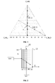
- the figure 1 represents a ternary diagram corresponding to different mixtures of these three compounds used in different compositions of model species.
- this diagram are represented two specific straight lines called conjugation straight line of ethanol, referenced DC1, and conjugation straight line of toluene, referenced DC2.
- the conjugation line of ethanol, DC1 corresponds to an equivolumic composition of toluene and isooctane in which the percentage by volume of ethanol varies from 0 to 100%. This conjugation line makes it possible to evaluate the impact of the addition of oxygen compounds on the fuel tanks.
- conjugation line of toluene corresponds to an equivolumic composition of ethanol and isooctane, in which the percentage by volume of toluene varies between 0 and 100%.
- conjugation lines have a point of intersection I which makes it possible to check the coherence of the experimental values obtained for these two lines.
- gasoline compositions E1 to Ey are chosen, for example between 5 and 10 different compositions, preferably between 6 and 8, along at least one of the two conjugation lines, for example along the conjugation line of ethanol DC1.
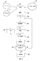
- the permeability of a monolayer polymer membrane 10 is essentially based on the "sorption-diffusion" model, as illustrated in FIG. figure 2 .
- a first measurement consists in measuring the SORP sorption on the upstream face 11 of the membrane 10, that is to say the face in direct contact with the liquid mixture L.
- the membrane 10 selectively swells against the liquid mixture The adjacent.
- the selectivity is due to the affinity of the material forming the membrane with the various compounds present in the liquid mixture L. This means that the composition of the liquid entering the upstream face 11 of the membrane 10 is generally very different from that of the mixture.
- a second measurement is to measure the diffusion DIFF, that is to say the amount of material that diffuses from the upstream face 11 to the downstream face 12 of the membrane 10.
- the DIFF diffusion is kinetic.
- the first named material is the one that is in contact with the liquid mixture.
- the binder layer is upstream, in contact with the liquid mixture, and the EVOH is downstream.
- FIG. 3 represents a block diagram of the modeling method according to the invention.
- Steps 10, 11, 12, and 13 Input Data and Initialization of the Calculation
- the modeling is based on experimental measurements of sorption and diffusion made, at 50 ° C, on each of the monolayers constituting the multilayer structure, for the whole range of compositions of the ternary system ethanol / isooctane / toluene.
- step 10 for each of the E1 to Ey model gasoline compositions chosen (step 10 ), preliminary experimental measurements of sorption and diffusion are carried out on polymer monolayers, with a thickness of between 25 and 200 ⁇ m, falling within the constitution of the multilayer structure ( STRUCT 11 ) for which the calculation of permeability to gasolines must be carried out.
- these measurements make it possible to know the behavior of each of the solvents of the gasoline in each of the polymer materials of the multilayer structure, taken in isolation.
- the swelling of a monolayer polymer by solvents can be considered as a thermodynamic equilibrium between two different phases.
- the dry polymer which is in contact with the solvents, creates a chemical potential gradient. This difference in chemical potential acts as a driving force to ensure the transfer of material and the penetration of solvent molecules into the polymer material.
- a stationary state is established with the presence of a constant amount of solvent in the polymer. From the point of view of thermodynamics, this equilibrium results in an equality of the chemical potentials of the different solvents in the liquid phase, that is to say in the model gasoline, and in the solid phase, that is to say say the swollen polymer.
- the measurement of sorption then consists in determining the overall swelling and the partial swellings of the polymer in a thermodynamically equilibrium liquid, which corresponds to obtaining a constant mass for the swollen polymer.
- This sorption measurement is carried out for each of the solvents of each of the gasoline compositions chosen E1 to Ey in step 10.
- the polymer of The formation of a monolayer is immersed in each E1 gasoline composition at Ey and swollen polymer mass measurements are made to constant mass, which may take several months.
- the partial swellings relative to each component of the gasoline after the desorption of the solvents for each gasoline composition are then measured, the quantification being carried out by gas chromatography.
- Diffusion for its part, is an irreversible transport phenomenon that results in a migration of chemical species in a medium from areas of greater chemical potential to those with lower chemical potential. This phenomenon is for example described by the first law of Fick which states that the diffusion flux is proportional to the concentration gradient.
- the diffusion measurement consists of measuring, under steady state conditions, partial flows of each solvent for each E1 model gasoline composition with Ey migrating in time through a monolayer of polymer, that is to say the amount of a compound passing through the monolayer per unit of time and surface. This measurement is advantageously carried out by means of a permeameter coupled to a gas chromatograph for on-line analysis of the permeate.
- the experimental measurements thus produced then constitute input data DE (step 13) for the method for modeling the permeation of a multilayer structure.
- Sorption measurements are carried out to determine the composition of the swollen polymer at 50 ° C., for different model gasoline compositions corresponding to at least one of the two conjugation straight lines of ethanol. or toluene.
- the activities of the various solvents in the swollen polymer are then calculated from the sorption measurements made to determine the composition of a swollen polymer at 50 ° C. These calculations are performed using the UNIQUAC model applied to quaternary systems (ethanol / isooctane / toluene / swollen polymer).
- the binary polymer / solvent interaction parameters of the UNIQUAC model are finally adjusted so that the results of the modeling and the results of the measurements converge and thus obtain an optimized thermodynamic law of optimized sorption (12) for each monolayer.
- the generalization of the model is then possible and the calculation of the activities of the three solvents in an inflated polymer can be carried out when the composition of the swollen polymer is known.
- DIFF diffusion laws step 12
- Measuring the partial flows of each compound of the gasoline composition through each monolayer makes it possible to obtain, for each monolayer, a model that gives a kinetic distribution law for each compound.
- the concentrations of the three solvents upstream of the structure that is to say at the entry of the first monolayer of the multilayer structure, are known and fixed by the experimental data.
- the concentrations downstream that is to say at the exit of the last monolayer of the multilayer structure, are always considered equal to zero.
- the boundary conditions upstream and downstream of the multilayer structure are thus defined for the numerical calculation of the partial flows.
- n monolayers can be formally considered as a succession of (n-1) bilayers, each bilayer comprising an upstream monolayer A and a downstream monolayer B, the predictive calculations for a multilayer structure are made. according to a repetition of calculations on the different bilayer involved.
- Steps 14 to 21 treatment for each composition E1 to Ey (possibly be carried out indifferently in parallel or in series),
- the next step 14 of the modeling method consists of initializing the concentration profiles in the multilayer structure.
- the multilayer structure is discretized in space and time.
- the discretization of the multilayer structure in space is schematized on the figure 4 .
- the multilayer structure, of thickness e is virtually cut into sufficiently numerous elementary slices, so as to account for the variations of the quantities in each slice. This cutting is performed according to the thickness e of the structure, which corresponds to the direction of transfer of the three solvents.
- the number X of elementary slices is for example between 45 and 55 for each monolayer of polymer. It is for example set at 50 for each monolayer of polymer.
- c n of constitution of the multilayer structure, has a thickness, respectively e1 ... e n , which is specific.
- the number of monolayers constituting the multilayer structure is for example limited to 7. However, this number may naturally be higher depending on the nature of the multilayer structure to be studied.
- each monolayer is centered in the first and last elementary slices which make it possible to account for the entry and the exit of each monolayer.
- the last elementary slice of the upstream layer A and the first elementary slice of the downstream layer B are overlapping.
- the actual thickness e of the multilayer structure is between the center of the first elementary slice and the center of the last elementary slice of the structure.
- the thicknesses ⁇ (i) of each elementary slice are recalculated according to a monodirectional expansion rule.
- the swelling of the structure is considered to be monodirectional. It takes place in the same direction as the migration of solvent species from the model gasoline.
- the expansion of the thickness of the slices, induced by the swelling of the polymer is calculated by virtue of an Expan expansion coefficient (i) which depends on the volume of the solvent V 1 absorbed in the polymer and on the volume V 0 of the dry polymer.
- the swelling phenomenon tends to reduce concentration gradients due to the increased thickness of the membrane. After having calculated the thickness of an elementary slice ⁇ (i) of swollen polymer, it is then possible to estimate the concentration gradient of each solvent accordingly in each elementary slice.
- an increment of the time dt makes it possible to calculate a material balance in each elementary slice of the structure. This material balance then makes it possible to estimate concentration profiles of each of the solvents in the multilayer structure.
- the next step 15 of the modeling process is to calculate the partial streams.
- the first law of Fick according to which the flux of diffusion is proportional to the gradient of concentration.
- the first law of Fick is applied for each so-called “mixed" slice, that is to say for each slice composed of two neighboring half-slices, of thickness referenced ⁇ m (i) on the figure 4 , to calculate the partial streams of diffusion across each slice interface. The calculation is made from the local concentration values and the thickness of each slice previously calculated in step 14.
- account is also taken of partial convection flows. Knowing that the total measured partial flow is equal to the sum of the partial diffusion flows and the partial convection flows, the partial convection flows are deduced from the calculated local concentrations and the measured overall partial flow. In this case, an iterative calculation is performed to take into account the convection flows. This calculation is continued until the variation of the partial flows becomes negligible.
- the next step 16 is to perform a treatment at the interface between each monolayer of polymer involved in the constitution of the multilayer polymer structure.
- two kinds of limitations to transfer to the interface can generally be distinguished.
- the example of a bilayer film, comprising an upstream monolayer A and a downstream monolayer B, is described below.
- the first limitation concerns the case where the downstream monolayer B is more permeable to a species than the upstream monolayer A.
- the concentration profile of this species in the upstream monolayer A will become steep to respond to the depletion created by the downstream monolayer B.
- the evacuation is then faster than the feeding, so no species accumulation occurs at the interface.
- the concentration of this species in the downstream monolayer B will therefore be low. Consequently, the activity profile is also discontinuous because no equilibrium is established at the interface, and the transfer is controlled solely by the upstream diffusion laws, which corresponds to a kinetic limitation.
- the second limitation concerns the case where, symmetrically, the downstream monolayer B has a greater barrier effect than the upstream monolayer A for a given species.
- the concentration profile of this species in the upstream monolayer A will flatten out to allow an equal flow on both sides of the interface.
- an accumulation of material then occurs in the upstream monolayer A.
- This accumulation of material is nevertheless limited by the sorption thermodynamics, which sets the maximum limit of the concentrations of each solvent for each polymer for the activities in question. This maximum theoretical limit can be calculated by considering a thermodynamic equilibrium at the interface. This equilibrium translates into equal activity for all species on both sides of the interface. In this case, the activity profiles are therefore continuous over the entire bilayer.
- the limiting factor is then the ceiling of sorption which is fixed by the thermodynamic properties. This particular case therefore corresponds to a thermodynamic limitation.
- the concentration profiles through a multilayer structure are discontinuous at the interfaces between the different monolayers.
- the profile differs according to the properties of each polymer and of each solvent considered.
- To be able to calculate such a concentration profile it is assumed that there is a continuity of activity of each species in the stationary regime in the case of equilibrium at the interface.
- the sorption ceilings for each downstream monolayer B are estimated by assuming a thermodynamic equilibrium between the two adjacent slices.
- a known sorption model such as the UNIQUAC model for example.
- step 17 a material balance is then carried out by applying the second law of Fick which concerns the variation of the concentration in time and in space.
- This calculation step makes it possible to change the local concentration of each solvent of the gasoline composition considered in each elementary slice, and therefore the concentration profile in the multilayer structure, as a function of time.
- the concentration profiles and the partial flows are modified at each incrementation of the time dt, by applying slice material budgets to the whole of the multilayer structure.
- the concentration variation is calculated from a time increment dt and the partial flow balance. It must be limited by choosing a time increment adapted to ensure the convergence of the calculation, when the monolayers in particular have very different permeabilities. In fact, the most permeable material strongly contributes to limiting the rate of change of concentration profiles in the least permeable materials by imposing low values to the increment of time dt. This results in an increase which can be very important in the calculation time necessary to reach a steady state.
- This way of discretizing the multilayer structure over time generally makes it possible to avoid the problems of divergence of the calculation. In this way, the material balances in each layer remain consistent, i.e., the output flow is equal to the input flow, while accelerating profiling in the least permeable materials.
- Step 19 After adjusting the increment of time dt and establishing the variation of the local concentrations, the time is incremented by dt.
- Step 20 The PROF concentration profiles of each model gasoline compound in the multilayer structure are updated, and the corresponding thicknesses of the elementary slices are adjusted taking into account the unidirectional swelling of the multilayer structure.
- Step 21 A test is performed to check whether the calculated partial flows are conservative throughout the structure, ie if the flux variations are very small at any point in the structure. In fact, the flow variation must be less than 1/1000 of the overall flow. As soon as the flows are identical at any point in the structure, the calculations are complete, otherwise the calculation loops back to the first step of the estimation of the diffusion flows and the convection flows (step 15). The calculation is also adapted according to the error obtained on the flow conservation criterion. When the system reaches the steady state, the concentration profiles and the partial flows are stored.
- an error function is calculated by comparing the calculated and experimental flows.
- the calculation ends and the optimized parameters are saved as well as the concentration profiles, the partial flows and the various characteristics of the studied system.
- the modeling thus carried out makes it possible to optimize a multilayer polymer structure for a reservoir from the calculations. It saves a lot of time, and therefore money, in the design of tanks. Typically, a calculation requires 1 day while measurements take more than a year for industrial fuel tanks. In addition, this modeling also makes it possible to define a stacking order of the different materials and to adjust their thicknesses. Finally, thanks to the modeling, it is possible to be interested in new materials and to design new structures not envisaged until now.
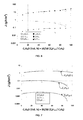
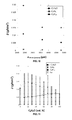
- a material transfer modeling was carried out on a bilayer structure and the results of the modeling were compared with the values measured experimentally on this same bilayer structure. The results of these comparisons are represented on the curves of the figure 5 .
- the bilayer structure is a film comprising a layer of binder 9 ⁇ m thick and a layer of HDPE (high density polyethylene) 24 microns thick. The essence is on the side of the upstream layer, that is to say the binder layer.
- the binder used is maleic anhydride grafted LLDPE, in other words it is linear low density polyethylene grafted maleic anhydride, LLDPE being the acronym for "Linear Low-Density PolyEthylene".
- a gasoline composition when a gasoline composition comprises 10% ethanol, it comprises 45% of isooctane and 45% of toluene. Similarly, when another gasoline composition comprises 60% ethanol, it comprises 20% iso-octane and 20% toluene.
- the partial flows of the various gasoline compounds were measured and modeled for a temperature of 50 ° C. Empty symbols correspond to the measurements, while the curves with the full symbols correspond to the calculations.
- the multilayer structure more specifically comprises the following layers: HDPE (High-density polyethylene) / Binder (maleic anhydride grafted LLDPE / EVOH (Poly (Ethylene-co-vinyl alcohol)) / Binder / HDPE Calculated on the other hand at 50 ° C, with a gasoline model E20 comprising 20% ethanol, 40% iso octane and 40% toluene by volume.
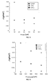
- the Figure 8 shows the evolution of the partial flows of the different solvents of the E20 gasoline as a function of the thickness of the EVOH layer. It is found that the toluene flux decreases rapidly when the thickness of this polymer, placed in the middle of the structure, increases. The flow of iso octane is less influenced because it is already extremely low. However, it is interesting to note that the flow of ethanol seems on the contrary to increase with the thickness of EVOH in the multilayer. In summary, increasing the thickness of the EVOH layer makes it possible to significantly reduce hydrocarbon fluxes, to the detriment of the overall barrier effect on ethanol.
- the Figures 9 and 10 show the influence of the thickness of the HDPE layers respectively downstream and upstream of the structure.
- increasing the thickness of one or other of these HDPE layers makes it possible to reduce the partial flows of ethanol and toluene, whereas the effect is less clear on the flow of the iso-octane already extremely low for the multilayer structure considered.
- the permeability reduction effect is greater if the thickness of the upstream layer of HDPE increases compared to that of the downstream layer.
- the upstream layer of HDPE is in direct contact with the model fuel mixture, it plays a protective role for the following layers, including EVOH.
- the downstream layer of HDPE its role is less because it comes after two layers of polymers with strongly antagonistic effects.
- compositions of model gasoline vary greatly on the international scale according to the producers and the legislations.
- the share of additives from biological pathways, such as bio-ethanol, can wait up to 80% even 100% in some countries such as Brazil. Therefore, it is important to ensure that with such a wide variety of fuels, the barrier effect of tanks for fuel remains sufficient to meet international environmental standards.
- the predictions were made for a film of 5 layers HDPE / Binder / EVOH / Binder / HDPE with the respective thicknesses 2400/100/100/100/1000 in microns for each of the layers.
- the compositions of the fuel model mixtures are those based on the conjugation straight line of ethanol, that is to say on gasoline models containing increasing ethanol content contents ranging from 0 to 100% and proportions equivalents of isooctane and toluene.
- the Figure 11 allows to evaluate the influence of the composition of this model essence on the partial and global flows J Tot .
- the iso- octane flux is always much lower than the fluxes of the two other solvents and does not show any significant variation over the range of compositions. studied.
- the flow of ethanol meanwhile, is almost constant up to a content of 50% ethanol, and then increases slightly for even more enriched mixtures of alcohol.
- the role of the upstream layer of HDPE appears very important to limit the flux of this polar compound.
- the compound most influenced by a change in composition of model gasoline is toluene.
- the Figure 11 shows that the flow of toluene goes through a maximum for a low ethanol content (about 10%) and then decreases sharply when the alcohol content increases.
- the studied film is thus composed of 5 layers EVOH / Binder / HDPE / Binder / EVOH, with respective thicknesses of each of the layers of 50/100/500/100/50 in microns, whose permeability was simulated for a model mixture of ethanol / isooctane / toluene fuels of 20/40/40 volume composition.
- this arrangement of the different layers does not appear realistic for an industrial application due in particular to the high sensitivity to moisture of the EVOH. Nevertheless, the study of this arrangement makes it possible to give a comparison with the inverse arrangement widely used in the industry. The results of this comparison are summarized in Table I below.
- the overall permeability is increased by 40% when the EVOH is placed on both outer sides due to a partial flow of ethanol about twice higher.
- this multilayer with the inverted arrangement provides a better barrier effect vis-à-vis the hydrocarbons.
- the modeling method according to the invention thus makes it possible to predict all the partial flows of the various solvents (ethanol, isooctane and toluene) through multilayer structures which consist of several layers of polymers of different natures and thicknesses. .
- the method also makes it possible to optimize, on the one hand, the thickness of the various layers of the structure and, on the other hand, the stacking order of the materials constituting the different layers of the multilayer structure.
- reservoir structures can be modeled quickly from these calculations, to best meet environmental standards.
- this modeling method is advantageously implemented by means of a computer program, comprising program code instructions for executing the steps of the method, the program being itself executed by a processor.
Landscapes
- Chemical & Material Sciences (AREA)
- Chemical Kinetics & Catalysis (AREA)
- Biochemistry (AREA)
- Health & Medical Sciences (AREA)
- Life Sciences & Earth Sciences (AREA)
- Analytical Chemistry (AREA)
- Physics & Mathematics (AREA)
- General Health & Medical Sciences (AREA)
- General Physics & Mathematics (AREA)
- Immunology (AREA)
- Pathology (AREA)
- Dispersion Chemistry (AREA)
- Laminated Bodies (AREA)
Description
La présente invention concerne le domaine de la perméation aux mélanges de solvants d'une structure polymère multicouche. Par perméation on entend le transport d'un fluide, tel qu'un mélange de solvants, au travers d'une membrane. Plus précisément, il s'agit de la quantité de chacun des composants d'un mélange de solvants, traversant une structure polymère multicouche.The present invention relates to the field of permeation to solvent mixtures of a multilayer polymeric structure. By permeation is meant the transport of a fluid, such as a mixture of solvents, through a membrane. More specifically, it is the amount of each of the components of a solvent mixture, passing through a multilayer polymer structure.
Plus particulièrement, l'invention se rapporte à un procédé de modélisation de perméation aux mélanges de solvants d'une structure polymère multicouche, notamment aux essences et plus particulièrement aux essences de type carburants. L'invention se rapporte enfin à un programme d'ordinateur mettant en oeuvre le procédé de modélisation.More particularly, the invention relates to a permeation modeling method for solvent mixtures of a multilayer polymer structure, in particular for gasolines and more particularly for gasolines of the fuel type. The invention finally relates to a computer program implementing the modeling method.
Un récipient, en particulier un réservoir de carburant, comprenant une structure polymère multicouche dont la perméation est modélisée selon le procédé de modélisation, est par ailleurs décrit.A container, in particular a fuel tank, comprising a multilayer polymer structure whose permeation is modeled according to the modeling method, is furthermore described.
Historiquement, les conteneurs ou les réservoirs utilisés pour le stockage ou le transport de produits chimiques étaient fabriqués en métal. Ces pièces en métal sont progressivement remplacées par des matériaux plastiques monocouches, plus légers, plus faciles à mettre en oeuvre, permettant de réaliser des réservoirs aux géométries complexes, non sensibles à la corrosion. Toutefois ces réservoirs plastiques monocouches ne satisfont plus à la réglementation des émissions et il convient donc de développer des solutions plastiques plus performances en termes de propriétés barrières que les solutions monocouches. Une voie utilisée industriellement aujourd'hui est la structure plastique multicouche alliant différents matériaux judicieusement choisis, afin d'augmenter les propriétés barrières de ladite structure. Le secteur du transport notamment cherche constamment à alléger les véhicules, pour diminuer leurs émissions et leur consommation énergétique. Cependant, ces matériaux légers doivent répondre aux normes d'étanchéité les plus strictes. De ce fait, la paroi polymère d'un réservoir de carburant doit avoir de bonnes propriétés barrières pour limiter le transfert massique des carburants dans l'environnement. Le mot barrière est utilisé dans la description pour décrire des matériaux barrières aux essences. Pour jouer au mieux son rôle de barrière, la paroi du réservoir est notamment formée d'une structure polymère multicouche, chacune des couches jouant un rôle de barrière pour l'un au moins des composés du carburant.Historically, containers or tanks used for storing or transporting chemicals were made of metal. These metal parts are gradually replaced by monolayer plastic materials, lighter, easier to implement, for making tanks with complex geometries, not sensitive to corrosion. However, these single-layer plastic tanks no longer comply with emission regulations, and plastic solutions need to be developed with greater performance in terms of barrier properties than single-layer solutions. One way used industrially today is the multilayer plastic structure combining different carefully chosen materials, in order to increase the barrier properties of said structure. In particular, the transport sector is constantly seeking to lighten vehicles, to reduce their emissions and their energy consumption. However, these lightweight materials must meet the strictest sealing standards. As a result, the polymer wall of a fuel tank must have good barrier properties to limit the mass transfer of fuels into the environment. The word barrier is used in the description to describe barrier materials to essences. To best play its role of barrier, the tank wall is formed in particular of a multilayer polymer structure, each layers acting as a barrier for at least one of the fuel compounds.
Les normes environnementales sont de plus en plus drastiques pour réduire au maximum les émissions d'hydrocarbures dans l'environnement. Ainsi, la norme Européenne Euro V, en vigueur depuis septembre 2009, limite l'émission à 2,0 g par test, un test pouvant durer jusqu'à 36 heures. La norme Américaine PZEV (acronyme anglais pour « Partial Zero Emission Vehicle ») limite les émissions à 0,35 g par test de 3 jours pour le véhicule entier. Par conséquent, dans ce contexte, il faut optimiser les parois des réservoirs de carburants, en optimisant leur perméation aux essences, afin de limiter au maximum toute perte de carburant dans l'environnement.Environmental standards are becoming increasingly stringent to minimize hydrocarbon emissions into the environment. For example, the European Euro V standard, in force since September 2009, limits the emission to 2.0 g per test, a test that can last up to 36 hours. The American PZEV standard limits emissions to 0.35 g per 3-day test for the entire vehicle. Therefore, in this context, it is necessary to optimize the walls of the fuel tanks, optimizing their permeation to gasoline, in order to minimize any loss of fuel in the environment.
Une essence est un mélange de composés aromatiques, aliphatiques et d'un composé oxygéné, très souvent de l'alcool. Or les polymères ne sont pas barrières à tous les composés contenus dans une essence et tous les polymères ne sont pas barrières aux mêmes composés contenus dans une essence. Ainsi, le polyéthylène par exemple fait barrière à l'alcool, mais pas au toluène, qui est un composé aromatique constituant de l'essence.A gasoline is a mixture of aromatic, aliphatic compounds and an oxygenated compound, very often alcohol. But polymers are not barriers to all compounds in a gasoline and all polymers are not barriers to the same compounds in a gasoline. Thus, polyethylene, for example, is a barrier to alcohol, but not to toluene, which is an aromatic compound constituting gasoline.
Les matériaux clés utilisés dans les structures barrières se caractérisent par de faibles niveaux de gonflement lorsqu'ils sont mis au contact des essences, et par une mobilité réduite des petites molécules diffusantes dans la matrice polymère. Ceci impose des délais de mise en équilibre très longs pour les structures industrielles de réservoir multicouches, typiquement de l'ordre de l'année. De plus, l'étude expérimentale de ces phénomènes nécessite d'accumuler de nombreuses mesures. Ces considérations ont conduit la demanderesse à réaliser ces caractérisations à partir de films beaucoup plus minces que ceux qui sont mis en oeuvre dans les parois de réservoirs. En effet, chaque fois que l'épaisseur d'un film est divisée par deux, son délai de demi sorption/désorption est approximativement divisé par quatre et le flux de matière est amplifié par un facteur deux. Les mesures expérimentales restent très consommatrices de temps puisqu'elles durent en moyenne de 1 à 3 mois pour des lignes essence d'1 mm d'épaisseur et au moins un an pour des réservoirs d'épaisseur minimum de 3 mm.The key materials used in the barrier structures are characterized by low levels of swelling when they are brought into contact with the species, and by reduced mobility of the small scattering molecules in the polymer matrix. This imposes very long equilibrium delays for industrial multilayer tank structures, typically of the order of the year. Moreover, the experimental study of these phenomena requires the accumulation of numerous measurements. These considerations led the applicant to perform these characterizations from much thinner films than those implemented in the tank walls. Indeed, each time the thickness of a film is halved, its half sorption / desorption time is approximately divided by four and the flux of material is amplified by a factor of two. The experimental measurements are very time consuming since they last on average from 1 to 3 months for
Au vu du temps extrêmement long pour obtenir des mesures permettant de valider ou non des structures polymères multicouches en vue de la réalisation de la paroi d'un réservoir, il est apparu nécessaire de développer des modèles pour faire une pré-sélection des structures utilisables qui répondent aux normes. Une telle modélisation permet de valider des structures en 1 jour lorsque les expérimentations mettent plusieurs mois.In view of the extremely long time required to obtain measurements that make it possible to validate or not multi-layer polymeric structures with a view to achieving the tank wall, it became necessary to develop models to pre-select usable structures that meet the standards. Such a modelization makes it possible to validate structures in 1 day when the experiments put several months.
Il existe des modèles pour prédire la perméabilité à travers des structures multicouches, mais ces modèles sont réalisés dans le cadre de l'étude de la perméabilité aux gaz simples, tels que le dioxyde de carbone CO2, l'oxygène O2, ou l'azote N2, ou encore à la vapeur d'eau. Ces modèles permettent par exemple de prédire la durée de conservation des aliments en estimant la perméabilité à l'oxygène d'une membrane multicouche entourant les aliments. En revanche ces modèles ne permettent pas de prédire la perméabilité de structures multicouches à une essence. En effet, une essence est un mélange de solvants et la composition de l'essence varie dans l'épaisseur de la structure multicouche en fonction de la nature et de l'épaisseur de la couche traversée. Différents paramètres doivent donc être pris en compte comme par exemple les interactions du type essence / polymère (sorption), la résistance à l'interface entre deux couches polymères et la diffusion de l'essence, et de chacun de ses constituants, dans chaque couche.There are models for predicting permeability through multilayer structures, but these models are realized as part of the study of the permeability to simple gases, such as carbon dioxide CO 2 , oxygen O 2 , or carbon dioxide. nitrogen N 2 or steam. These models allow, for example, to predict the shelf life of foods by estimating the oxygen permeability of a multilayer membrane surrounding foods. On the other hand, these models do not make it possible to predict the permeability of multilayer structures to a gasoline. Indeed, a gasoline is a mixture of solvents and the composition of the gasoline varies in the thickness of the multilayer structure depending on the nature and thickness of the layer passed through. Different parameters must therefore be taken into account, such as the interactions of the gasoline / polymer (sorption) type, the resistance at the interface between two polymer layers and the diffusion of the gasoline, and of each of its constituents, in each layer. .
A partir de lois de diffusion (Loi de Fick à titre d'exemple) et de lois de sorption (Modèle Uniquac à titre d'exemple), définies pour chaque monocouche, on prévoit le comportement de structures multicouches, associant des matériaux différents, et on valide ainsi ou non des structures de réservoirs vis-à-vis des normes environnementales de plus en plus sévères.From diffusion laws (Fick's law by way of example) and from sorption laws (Uniquac model by way of example), defined for each monolayer, the behavior of multilayer structures, associating different materials, is predicted. it validates or not tank structures vis-à-vis environmental standards increasingly severe.
On connait également par le document intitulé « Modeling of fuel permeation in multilayer automotive plastic fuel tanks », publié en avril 2011 par Messieurs Benrabah, Thibault et DiRaddo, un procédé de modélisation de la perméation aux essences de matériaux multicouches, type réservoirs, mais les hypothèses retenues dans ce procédé sont très limitatives, ne s'appliquent pas à l'ensemble des couches des réservoirs décrits et ne permettent pas en conséquence d'obtenir un résultat fiable.Also known by the document entitled "Modeling of fuel permeation multilayer automotive plastic fuel tanks", published in April 2011 by Messrs. Benrabah, Thibault and DiRaddo, a method for modeling the permeation of species of multilayer materials, reservoirs type, but the Assumptions made in this process are very limiting, do not apply to all the layers of the tanks described and therefore do not allow to obtain a reliable result.
L'invention a donc pour but de remédier à au moins un des inconvénients de l'art antérieur. L'invention vise notamment à permettre de modéliser le comportement d'une essence dans une structure polymère multicouche afin de valider ou non, de manière simple, rapide et efficace une structure de réservoir.The invention therefore aims to remedy at least one of the disadvantages of the prior art. The invention aims in particular to make it possible to model the behavior a gasoline in a multilayer polymer structure to validate or not, simply, quickly and efficiently a tank structure.
A cet effet, l'invention a pour objet un procédé de réalisation d'un modèle de perméation aux mélanges de solvants d'une structure polymère multicouche à n monocouches (n≥2), selon l'énoncé de la revendication indépendante 1.To this end, the subject of the invention is a method for producing a model for permeation to solvent mixtures of a multilayer polymeric structure with n monolayers (n≥2), according to the statement of
Selon une autre caractéristique, le mélange de solvants est une essence comprenant un mélange d'au moins deux composés choisis parmi un composé oxygéné (a), un composé aliphatique (b) et un composé aromatique (c), dans des proportions différentes. Plus particulièrement, l'essence comprend un mélange d'au moins un composé oxygéné (a), un composé aliphatique (b) et un composé aromatique (c), dans des proportions différentes.According to another characteristic, the solvent mixture is a gasoline comprising a mixture of at least two compounds chosen from an oxygenated compound (a), an aliphatic compound (b) and an aromatic compound (c), in different proportions. More particularly, the gasoline comprises a mixture of at least one oxygenated compound (a), an aliphatic compound (b) and an aromatic compound (c), in different proportions.
La modélisation de la perméation aux essences d'une structure multicouches permet ainsi de prédire l'ensemble des flux partiels des différents solvants (éthanol, iso-octane et toluène) à travers des structures multicouches qui se composent de plusieurs couches de polymères de natures et d'épaisseurs différentes. Le procédé de modélisation permet donc d'optimiser des structures de réservoir à partir de calculs et permet de gagner du temps, et donc de l'argent, sur la conception des réservoirs. Le procédé permet en outre d'optimiser d'une part l'épaisseur des différentes couches de la structure et d'autre part, l'ordre d'empilement des matériaux constituant les différentes couches de la structure multicouches.The modeling of the gas permeation of a multilayer structure thus makes it possible to predict all the partial flows of the various solvents (ethanol, isooctane and toluene) through multilayer structures which consist of several layers of polymers of natures and of different thicknesses. The modeling process therefore makes it possible to optimize reservoir structures from calculations and saves time, and therefore money, on the design of the tanks. The method also makes it possible, on the one hand, to optimize the thickness of the different layers of the structure and secondly, the stacking order of the materials constituting the different layers of the multilayer structure.
Selon d'autres caractéristiques optionnelles du procédé :
- préalablement à l'étape 2c.1. d'estimation des flux partiels, une étape d'initialisation consiste à calculer, à partir des valeurs de sorption en entrée et en sortie de la structure multicouche, des activités correspondantes de chacun des composés de ladite composition de mélange de solvants en entrée et sortie de ladite structure, puis à créer un profil linéaire d'activité pour chacun des solvants de l'entrée à la sortie de la structure puis, à partir de ce profil d'activité, estimer des concentrations locales de chacun des composés de ladite composition de mélange de solvants dans chaque tranche de ladite structure multicouche, ainsi que l'épaisseur des tranches élémentaires en tenant compte d'un gonflement monodirectionnel de ladite structure multicouche,
- l'étape 2c.1. d'estimation des flux partiels consiste à estimer d'une part des flux de diffusion, à partir des concentrations locales de chacun des composés de ladite composition de mélange de solvants dans chaque tranche élémentaire, et d'autre part des flux de convection, à partir des flux partiels mesurés à l'étape 2a et des concentrations locales de chacun des composés de ladite composition de mélange de solvants dans chaque tranche élémentaire,
- le traitement à l'interface entre deux monocouches de matériaux polymère différents de l'étape 2c.2 se base sur le fait qu'il y a égalité des flux entre deux monocouches adjacentes et que la concentration de chacun des composés à l'entrée de la monocouche aval B ne peut dépasser le plafond de sorption,
- le plafond de sorption est calculé à partir des activités de chacun des composés de ladite composition de mélange de solvants, en supposant qu'il y a continuité d'activité entre la dernière tranche d'une monocouche amont A en chevauchement avec une première tranche d'une monocouche aval B,
- chaque composition d'essence E1 à Ey comprend un taux volumique (%) de l'un des composés (a) qui varie d'une composition à l'autre, tandis que les autres composés (b, c) présentent une proportion volumique identique,
- chaque composition d'essence comprend un mélange de plusieurs composés (a, b, c) choisis parmi l'éthanol (a), l'iso-octane (b), et le toluène (c),
- prior to step 2c.1. of partial flow estimation, an initialization step consists of calculating, from the input sorption values and at the outlet of the multilayer structure, corresponding activities of each of the compounds of said solvent mixture composition entering and leaving said structure, and then creating a linear profile of activity for each of the solvents from the inlet to the outlet of the structure then, from this activity profile, estimate local concentrations of each of the compounds of said solvent mixture composition in each slice of said multilayer structure, as well as the thickness of the elementary slices taking into account the a monodirectional swelling of said multilayer structure,
- step 2c.1. estimation of the partial flows consists in estimating on the one hand diffusion fluxes, from the local concentrations of each of the compounds of said solvent mixture composition in each elementary slice, and on the other hand convection flows, on the other hand from the partial flows measured in step 2a and the local concentrations of each of the compounds of said solvent mixture composition in each elementary slice,
- the treatment at the interface between two monolayers of different polymer materials from step 2c.2 is based on the fact that there is equality of flux between two adjacent monolayers and that the concentration of each of the compounds at the inlet of the downstream monolayer B can not exceed the sorption ceiling,
- the sorption ceiling is calculated from the activities of each of the compounds of said solvent mixture composition, assuming that there is continuity of activity between the last slice of an upstream monolayer A overlapping with a first slice of a downstream monolayer B,
- each gasoline composition E1 to Ey comprises a volume ratio (%) of one of the compounds (a) which varies from one composition to another, while the other compounds (b, c) have an identical volume proportion ,
- each gasoline composition comprises a mixture of several compounds (a, b, c) chosen from ethanol (a), iso-octane (b), and toluene (c),
Un récipient, qui ne fait pas partie de la présente invention, est réalisé dans une structure polymère multicouche dont la perméation aux mélanges de solvants est modélisée grâce au procédé de modélisation ci-dessus décrit.A container, which does not form part of the present invention, is made in a multilayer polymer structure whose permeation to solvent mixtures is modeled by means of the modeling method described above.
Enfin, selon l'énoncé de la revendication indépendante 11, l'invention se rapporte aussi à un programme d'ordinateur comprenant des instructions de code de programme pour l'exécution des étapes du procédé de modélisation ci-dessus décrit, lorsque ledit programme est exécuté par un processeur.Finally, according to the statement of the
D'autres particularités et avantages de l'invention apparaîtront à la lecture de la description qui est faite ci-après et qui est donnée à titre d'exemple illustratif et non limitatif, en regard des figures qui représentent :
- la
figure 1 , un schéma d'un diagramme ternaire correspondant à des mélanges de solvants utilisés dans des compositions d'essences modèles, - la
figure 2 , un schéma représentant un modèle de « sorption-diffusion » sur lequel repose la perméabilité d'une structure polymère monocouche, - la
figure 3 , un schéma de principe d'un procédé de modélisation selon l'invention, - la
figure 4 , un schéma de principe d'une structure multicouche virtuellement découpée en tranches élémentaires pour permettre un calcul numérique fin utilisé dans le procédé de modélisation selon l'invention, - la
figure 5 , des courbes représentant les flux partiels, mesurés et calculés, des différents composés d'une essence à différentes compositions dans une structure bicouche donnée, - la
figure 6 , des courbes représentant les flux partiels, mesurés et calculés, des différents composés d'une essence à différentes compositions dans une autre structure bicouche, - la
figure 7 , des courbes représentant les flux partiels, mesurés et calculés, des différents composés d'une essence à différentes compositions dans une autre structure tri-couche, - la
figure 8 , des courbes représentant les flux partiels calculés des différents composés d'une essence en fonction de l'épaisseur de la couche disposée au milieu d'une structure tricouche, - la
figure 9 , des courbes représentant les flux partiels calculés des différents composés d'une essence en fonction de l'épaisseur de la dernière couche de la même structure tricouche que lafigure 8 , - la
figure 10 des courbes représentant les flux partiels calculés des différents composés d'une essence en fonction de l'épaisseur de la première couche de la même structure tricouche que lafigure 8 , - la
figure 11 des courbes représentant les flux partiels calculés des différents composés d'une essence en fonction de la proportion volumique de composé oxygéné dans la composition d'essence, dans une structure 5 couches.
- the
figure 1 , a diagram of a ternary diagram corresponding to solvent mixtures used in model gasoline compositions, - the
figure 2 , a diagram representing a "sorption-diffusion" model on which the permeability of a monolayer polymer structure rests, - the
figure 3 , a block diagram of a modeling method according to the invention, - the
figure 4 a schematic diagram of a multilayer structure virtually divided into elementary slices to allow a fine numerical calculation used in the modeling method according to the invention, - the
figure 5 , curves representing the partial flows, measured and calculated, of the different compounds of a species with different compositions in a given bilayer structure, - the
figure 6 , curves representing the partial flows, measured and calculated, of the different compounds of a gasoline with different compositions in another bilayer structure, - the
figure 7 , curves representing the partial flows, measured and calculated, of the different compounds of a gasoline with different compositions in another tri-layer structure, - the
figure 8 curves representing the calculated partial flows of the different compounds of a gasoline as a function of the thickness of the layer disposed in the middle of a trilayer structure, - the
figure 9 , curves representing the calculated partial flows of the different compounds of a species according to the thickness of the last layer of the same three-layer structure as thefigure 8 , - the
figure 10 curves representing the calculated partial flows of the different compounds of a species according to the thickness of the first layer of the same three-layer structure as thefigure 8 , - the
figure 11 curves representing the calculated partial flows of the different compounds of a gasoline as a function of the volume proportion of oxygenated compound in the gasoline composition, in a 5-layer structure.
Dans la suite de la description, le terme essence désigne un mélange de solvants comprenant au moins deux composés choisis parmi un composé oxygéné (a), un composé aliphatique (b) et un composé aromatique (c), dans des proportions différentes. A titre d'exemple ce peut être un parfum ou un carburant.In the remainder of the description, the term essence designates a mixture of solvents comprising at least two compounds chosen from an oxygenated compound (a), an aliphatic compound (b) and an aromatic compound (c), in different proportions. For example, it can be a perfume or a fuel.
Dans l'exemple décrit ci-après il s'agit d'un carburant composé d'hydrocarbures aromatiques, d'hydrocarbures aliphatiques et d'un composé oxygéné. Dans le cas présent, une essence dite modèle est utilisée. Elle est composée de toluène (de formule C7H8, représentant les aromatiques), d'isooctane (de formule C8H18, représentant les aliphatiques) et d'éthanol (de formule C2H6O, représentant le composé oxygéné). Toutefois, l'invention ne se limite pas à ces composés.In the example described hereinafter, it is a fuel composed of aromatic hydrocarbons, aliphatic hydrocarbons and an oxygenated compound. In this case, a so-called model gasoline is used. It is composed of toluene (of formula C 7 H 8 , representing the aromatics), of isooctane (of formula C 8 H 18 , representing the aliphatics) and of ethanol (of formula C 2 H 6 O, representing the oxygenated compound ). However, the invention is not limited to these compounds.
La
Pour les besoins de la modélisation, on choisit plusieurs compositions d'essence différentes E1 à Ey, par exemple entre 5 et 10 compositions différentes, de préférence entre 6 et 8, le long d'au moins une des deux droites de conjugaison, par exemple le long de la droite de conjugaison de l'éthanol DC1.For the purposes of modeling, several different gasoline compositions E1 to Ey are chosen, for example between 5 and 10 different compositions, preferably between 6 and 8, along at least one of the two conjugation lines, for example along the conjugation line of ethanol DC1.
La perméabilité d'une membrane polymère monocouche 10 repose essentiellement sur le modèle « sorption-diffusion », tel qu'illustré sur la
Par convention, pour toutes les structures multicouches, le premier matériau nommé est celui qui se trouve au contact du mélange liquide. Par exemple, dans le cas d'une structure bicouche dénommée « Liant/EVOH », la couche de liant se trouve à l'amont, au contact du mélange liquide, et l'EVOH est à l'aval.By convention, for all multilayer structures, the first named material is the one that is in contact with the liquid mixture. For example, in the case of a bilayer structure called "Binder / EVOH", the binder layer is upstream, in contact with the liquid mixture, and the EVOH is downstream.
Pour pouvoir modéliser la perméabilité à une essence d'une structure multicouche, il faut connaître le comportement en sorption et en diffusion de chacun des composés de l'essence dans chaque polymère de constitution de la structure multicouches. C'est pourquoi, la modélisation repose sur des mesures expérimentales de sorption et de diffusion faites, à 50 °C, sur chacune des monocouches de constitution de la structure multicouche, pour toute la gamme de compositions du système ternaire ethanol/ iso-octane/toluène.To be able to model the permeability to an essence of a multilayer structure, it is necessary to know the sorption and diffusion behavior of each of the compounds of the essence in each polymer of constitution of the multilayer structure. Therefore, the modeling is based on experimental measurements of sorption and diffusion made, at 50 ° C, on each of the monolayers constituting the multilayer structure, for the whole range of compositions of the ternary system ethanol / isooctane / toluene.
A cette fin, pour chacune des compositions d'essence modèle E1 à Ey choisies (étape 10), des mesures expérimentales préalables de sorption et de diffusion sont réalisées sur des monocouches de polymère, d'épaisseur comprise entre 25 et 200 µm, entrant dans la constitution de la structure multicouche (STRUCT 11) pour laquelle le calcul de perméabilité aux essences doit être effectué. Ainsi, ces mesures permettent de connaître le comportement de chacun des solvants de l'essence dans chacun des matériaux polymère de la structure multicouche, pris isolément.For this purpose, for each of the E1 to Ey model gasoline compositions chosen ( step 10 ), preliminary experimental measurements of sorption and diffusion are carried out on polymer monolayers, with a thickness of between 25 and 200 μm, falling within the constitution of the multilayer structure ( STRUCT 11 ) for which the calculation of permeability to gasolines must be carried out. Thus, these measurements make it possible to know the behavior of each of the solvents of the gasoline in each of the polymer materials of the multilayer structure, taken in isolation.
Le gonflement d'un polymère monocouche par des solvants peut être considéré comme un équilibre thermodynamique entre deux phases différentes. Le polymère sec, qui est au contact des solvants, crée un gradient de potentiel chimique. Cette différence de potentiel chimique joue le rôle de force motrice pour assurer le transfert de matière et la pénétration des molécules de solvants dans le matériau polymère. Suite au régime transitoire, un état stationnaire s'établit avec la présence d'une quantité de solvant constante dans le polymère. Du point de vue de la thermodynamique, cet équilibre se traduit par une égalité des potentiels chimiques des différents solvants dans la phase liquide, c'est-à-dire dans l'essence modèle, et dans la phase solide, c'est-à-dire le polymère gonflé.The swelling of a monolayer polymer by solvents can be considered as a thermodynamic equilibrium between two different phases. The dry polymer, which is in contact with the solvents, creates a chemical potential gradient. This difference in chemical potential acts as a driving force to ensure the transfer of material and the penetration of solvent molecules into the polymer material. Following the transient state, a stationary state is established with the presence of a constant amount of solvent in the polymer. From the point of view of thermodynamics, this equilibrium results in an equality of the chemical potentials of the different solvents in the liquid phase, that is to say in the model gasoline, and in the solid phase, that is to say say the swollen polymer.
La mesure de sorption consiste alors, à déterminer le gonflement global et les gonflements partiels du polymère dans un liquide à l'équilibre thermodynamique, ce qui correspond à l'obtention d'une masse constante pour le polymère gonflé. Cette mesure de sorption est réalisée pour chacun des solvants de chacune des compositions d'essence choisies E1 à Ey à l'étape 10. Pour cela, le polymère de constitution d'une monocouche est immergé dans chaque composition d'essence E1 à Ey et des mesures de masse de polymère gonflé sont effectuées jusqu'à masse constante, ce qui peut prendre plusieurs mois. On mesure ensuite les gonflements partiels relatifs à chaque constituant de l'essence après la désorption des solvants pour chaque composition d'essence, la quantification étant réalisée par chromatographie en phase gazeuse.The measurement of sorption then consists in determining the overall swelling and the partial swellings of the polymer in a thermodynamically equilibrium liquid, which corresponds to obtaining a constant mass for the swollen polymer. This sorption measurement is carried out for each of the solvents of each of the gasoline compositions chosen E1 to Ey in
La diffusion, quant à elle, est un phénomène de transport irréversible qui se traduit par une migration d'espèces chimiques dans un milieu des zones de plus grand potentiel chimique vers celles de plus faible potentiel chimique. Ce phénomène est par exemple décrit par la première loi de Fick qui énonce que le flux de diffusion est proportionnel au gradient de concentration. La mesure de diffusion consiste à mesurer en régime stationnaire des flux partiels de chaque solvant pour chaque composition d'essence modèle E1 à Ey migrant dans le temps à travers une monocouche de polymère, c'est-à-dire la quantité d'un composé passant à travers la monocouche par unité de temps et de surface. Cette mesure est avantageusement réalisée au moyen d'un perméamètre couplé à un chromatographe en phase gazeuse pour l'analyse en ligne du perméat.Diffusion, for its part, is an irreversible transport phenomenon that results in a migration of chemical species in a medium from areas of greater chemical potential to those with lower chemical potential. This phenomenon is for example described by the first law of Fick which states that the diffusion flux is proportional to the concentration gradient. The diffusion measurement consists of measuring, under steady state conditions, partial flows of each solvent for each E1 model gasoline composition with Ey migrating in time through a monolayer of polymer, that is to say the amount of a compound passing through the monolayer per unit of time and surface. This measurement is advantageously carried out by means of a permeameter coupled to a gas chromatograph for on-line analysis of the permeate.
Les mesures expérimentales ainsi réalisées constituent alors des données d'entrée D.E (étape 13) pour le procédé de modélisation de la perméation d'une structure multicouche.The experimental measurements thus produced then constitute input data DE (step 13) for the method for modeling the permeation of a multilayer structure.
Par ailleurs, pour mettre en oeuvre le procédé de modélisation, il faut en outre disposer des lois de sorption SORP (étape 12) qui permettent de relier les activités des trois solvants aux concentrations mesurées à l'équilibre de sorption pour chaque matériau polymère. Pour pouvoir modéliser les équilibres de sorption, il faut connaître les activités des différents solvants dans les mélanges modèles de carburants utilisés. Le calcul des activités de l'éthanol, de l'iso-octane et du toluène de chaque composition d'essence modèle est effectué à 50°C, température choisie pour les mesures de sorption. Ce calcul est réalisé sur la base du modèle connu sous le nom d'UNIQUAC (UNlversal QUAsi Chemical theory) appliqué aux mélanges ternaires liquides correspondants. Des mesures de sorption sont effectuées pour déterminer la composition du polymère gonflé à 50°C, pour différentes compositions d'essences modèles correspondant à au moins l'une des deux droites de conjugaison de l'éthanol ou du toluène. Les activités des différents solvants dans le polymère gonflé sont ensuite calculées à partir des mesures de sorption effectuées pour déterminer la composition d'un polymère gonflé à 50°C. Ces calculs sont réalisés à l'aide du modèle UNIQUAC appliqué aux systèmes quaternaires (éthanol/iso-octane/toluène/polymère gonflé). Les paramètres d'interaction binaire polymère/ solvant du modèle UNIQUAC sont finalement ajustés pour que les résultats de la modélisation et les résultats des mesures convergent et obtenir ainsi une loi thermodynamique de sorption optimisée (12) pour chaque monocouche. La généralisation du modèle est alors possible et le calcul des activités des trois solvants dans un polymère gonflé peut être réalisé lorsque la composition du polymère gonflé est connue.Furthermore, to implement the modeling method, it is also necessary to have SORP sorption laws ( step 12 ) which make it possible to relate the activities of the three solvents to the concentrations measured at the equilibrium of sorption for each polymer material. To be able to model the sorption equilibrium, it is necessary to know the activities of the different solvents in the model mixtures of fuels used. Calculation of the activities of the ethanol, isooctane and toluene of each model gasoline composition is carried out at 50 ° C., the temperature chosen for the sorption measurements. This calculation is carried out on the basis of the model known under the name UNIQUAC (UNlversal QUAsi Chemical theory) applied to the corresponding liquid ternary mixtures. Sorption measurements are carried out to determine the composition of the swollen polymer at 50 ° C., for different model gasoline compositions corresponding to at least one of the two conjugation straight lines of ethanol. or toluene. The activities of the various solvents in the swollen polymer are then calculated from the sorption measurements made to determine the composition of a swollen polymer at 50 ° C. These calculations are performed using the UNIQUAC model applied to quaternary systems (ethanol / isooctane / toluene / swollen polymer). The binary polymer / solvent interaction parameters of the UNIQUAC model are finally adjusted so that the results of the modeling and the results of the measurements converge and thus obtain an optimized thermodynamic law of optimized sorption (12) for each monolayer. The generalization of the model is then possible and the calculation of the activities of the three solvents in an inflated polymer can be carried out when the composition of the swollen polymer is known.
Enfin, pour la mise en oeuvre du procédé de modélisation, il faut également disposer des lois de diffusion DIFF (étape 12) pour rendre compte de la variation des coefficients de diffusion de ces solvants en fonction de leur concentration locale dans chaque matériau polymère considéré. La mesure des flux partiels de chaque composé de la composition d'essence à travers chaque monocouche permet d'obtenir, pour chaque monocouche, un modèle qui donne une loi cinétique de diffusion pour chaque composé.Finally, for the implementation of the modeling method, it is also necessary to have DIFF diffusion laws (step 12) to account for the variation of the diffusion coefficients of these solvents as a function of their local concentration in each polymer material considered. Measuring the partial flows of each compound of the gasoline composition through each monolayer makes it possible to obtain, for each monolayer, a model that gives a kinetic distribution law for each compound.
Grâce à la mesure des équilibres de sorption pour les différents polymères, les concentrations des trois solvants en amont de la structure, c'est-à-dire à l'entrée de la première monocouche de la structure multicouche, est connue et fixée par les données expérimentales. Les concentrations en aval, c'est-à-dire à la sortie de la dernière monocouche de la structure multicouche, sont toujours considérées égales à zéro. On définit ainsi les conditions aux limites à l'amont et à l'aval de la structure multicouche pour le calcul numérique des flux partiels.By measuring the sorption equilibrium for the various polymers, the concentrations of the three solvents upstream of the structure, that is to say at the entry of the first monolayer of the multilayer structure, are known and fixed by the experimental data. The concentrations downstream, that is to say at the exit of the last monolayer of the multilayer structure, are always considered equal to zero. The boundary conditions upstream and downstream of the multilayer structure are thus defined for the numerical calculation of the partial flows.
Enfin, partant du principe qu'une structure multicouche à n monocouches peut être formellement considérée comme une succession de (n-1) bicouches, chaque bicouche comprenant une monocouche amont A et une monocouche aval B, les calculs prédictifs pour une structure multicouche sont réalisés selon une répétition de calculs sur les différentes bicouches impliquées.Finally, assuming that a multilayer structure with n monolayers can be formally considered as a succession of (n-1) bilayers, each bilayer comprising an upstream monolayer A and a downstream monolayer B, the predictive calculations for a multilayer structure are made. according to a repetition of calculations on the different bilayer involved.
Après avoir collecté toutes les données d'entrée D.E à prendre en compte pour la modélisation, l'étape suivante 14 du procédé de modélisation consiste à initialiser les profils de concentration dans la structure multicouche. Pour cela, la structure multicouche est discrétisée dans l'espace et dans le temps. La discrétisation de la structure multicouche dans l'espace est schématisée sur la
Les interfaces de chaque monocouche sont centrées dans les première et dernière tranches élémentaires qui permettent de rendre compte de l'entrée et de la sortie de chaque monocouche. A chaque interface entre deux monocouches de polymère adjacentes, la dernière tranche élémentaire de la couche amont A et la première tranche élémentaire de la couche aval B sont en chevauchement. Pour assurer la continuité des flux, les flux entrants et sortants qui correspondent à ces deux tranches en chevauchement sont maintenus égaux. L'épaisseur e réelle de la structure multicouche est comprise entre le centre de la première tranche élémentaire et le centre de la dernière tranche élémentaire de la structure. Une fois les compositions d'entrée et de sortie connues, les activités correspondantes sont également calculées en utilisant un modèle connu, tel que le modèle UNIQUAC par exemple. Ensuite, des profils linéaires d'activité sont créés pour chacun des solvants considérés de l'entrée à la sortie, de manière continue à travers toutes les monocouches composant la structure multicouche. Les concentrations locales Ci de chaque solvant de la composition d'essence modèle sont ensuite calculées pour chaque tranche, à partir des profils d'activité ainsi créés.The interfaces of each monolayer are centered in the first and last elementary slices which make it possible to account for the entry and the exit of each monolayer. At each interface between two adjacent polymer monolayers, the last elementary slice of the upstream layer A and the first elementary slice of the downstream layer B are overlapping. To ensure flow continuity, incoming and outgoing flows that correspond to these two overlapping slices are kept equal. The actual thickness e of the multilayer structure is between the center of the first elementary slice and the center of the last elementary slice of the structure. Once the input and output compositions are known, the corresponding activities are also calculated using a known model, such as the UNIQUAC model for example. Then, linear activity profiles are created for each of the considered solvents from the inlet to the outlet, continuously through all the monolayers composing the multilayer structure. The local concentrations Ci of each solvent of the model gasoline composition are then calculated for each slice, from the activity profiles thus created.
Compte tenu des concentrations locales, les épaisseurs ε(i) de chaque tranche élémentaire sont recalculées selon une règle d'expansion monodirectionnelle. Le gonflement de la structure est considéré comme étant monodirectionnel. Il a lieu dans la même direction que la migration des espèces de solvant de l'essence modèle. L'expansion de l'épaisseur des tranches, induite par le gonflement du polymère, est calculée grâce à un coefficient d'expansion Expan (i) qui dépend du volume dVi de solvant absorbé dans le polymère, et du volume V0 du polymère sec. L'épaisseur d'une tranche élémentaire ε(i), prenant en compte le gonflement, devient : ε(i)= ε0(i)×Expan(i), où ε0(i) représente l'épaisseur d'une tranche i de polymère sec. Le phénomène de gonflement tend à réduire les gradients de concentration en raison de l'augmentation de l'épaisseur de la membrane. Après avoir calculé l'épaisseur d'une tranche élémentaire ε(i) de polymère gonflé, il est ensuite possible d'estimer le gradient de concentrations de chaque solvant en conséquence dans chaque tranche élémentaire.Given the local concentrations, the thicknesses ε (i) of each elementary slice are recalculated according to a monodirectional expansion rule. The swelling of the structure is considered to be monodirectional. It takes place in the same direction as the migration of solvent species from the model gasoline. The expansion of the thickness of the slices, induced by the swelling of the polymer, is calculated by virtue of an Expan expansion coefficient (i) which depends on the volume of the
Concernant la discrétisation en temps, un incrément du temps dt permet de calculer un bilan de matière dans chaque tranche élémentaire de la structure. Ce bilan de matière permet ensuite d'estimer des profils de concentration de chacun des solvants dans la structure multicouche.With respect to discretization in time, an increment of the time dt makes it possible to calculate a material balance in each elementary slice of the structure. This material balance then makes it possible to estimate concentration profiles of each of the solvents in the multilayer structure.
A partir des concentrations locales de chacun des solvants, calculées à l'étape 14, l'étape suivante 15 du procédé de modélisation consiste à calculer les flux partiels. Ainsi, pour calculer les flux partiels de diffusion, on applique la première loi de Fick, selon laquelle le flux de diffusion est proportionnel au gradient de concentration. La première loi de Fick est appliquée pour chaque tranche dite « mixte », c'est-à-dire pour chaque tranche composée de deux demi-tranches voisines, d'épaisseur référencée εm(i) sur la
De manière avantageuse, il est en outre tenu compte des flux partiels de convection. Sachant que le flux partiel global mesuré est égal à la somme des flux partiels de diffusion et des flux partiels de convection, les flux partiels de convection sont déduits des concentrations locales calculées et du flux partiel global mesuré. Dans ce cas, un calcul itératif est réalisé pour la prise en compte des flux de convection. Ce calcul est poursuivi jusqu'à ce que la variation des flux partiels devienne négligeable.Advantageously, account is also taken of partial convection flows. Knowing that the total measured partial flow is equal to the sum of the partial diffusion flows and the partial convection flows, the partial convection flows are deduced from the calculated local concentrations and the measured overall partial flow. In this case, an iterative calculation is performed to take into account the convection flows. This calculation is continued until the variation of the partial flows becomes negligible.
L'étape 16 suivante consiste à effectuer un traitement à l'interface entre chaque monocouche de polymère entrant dans la constitution de la structure polymère multicouche. Selon les différentes configurations du film multicouche, on peut en général distinguer deux sortes de limitations au transfert à l'interface. Pour illustrer ces deux sortes de limitation au transfert, l'exemple d'un film bicouche, comprenant une monocouche amont A et une monocouche aval B, est décrit ci-après. The
La première limitation concerne le cas où la monocouche aval B est plus perméable à une espèce que la monocouche amont A. Dans ce cas, le profil de concentration de cette espèce dans la monocouche amont A va devenir pentu pour répondre à l'épuisement créé par la monocouche aval B. L'évacuation est alors plus rapide que l'alimentation, donc aucune accumulation d'espèce ne se produit à l'interface. La concentration de cette espèce dans la monocouche aval B sera donc faible. Par conséquent, le profil de l'activité est aussi discontinu, car aucun équilibre ne s'établit à l'interface, et le transfert est contrôlé uniquement par les lois de diffusion amont, ce qui correspond à une limitation cinétique.The first limitation concerns the case where the downstream monolayer B is more permeable to a species than the upstream monolayer A. In this case, the concentration profile of this species in the upstream monolayer A will become steep to respond to the depletion created by the downstream monolayer B. The evacuation is then faster than the feeding, so no species accumulation occurs at the interface. The concentration of this species in the downstream monolayer B will therefore be low. Consequently, the activity profile is also discontinuous because no equilibrium is established at the interface, and the transfer is controlled solely by the upstream diffusion laws, which corresponds to a kinetic limitation.
La deuxième limitation concerne le cas où, de façon symétrique, la monocouche aval B présente un effet barrière plus important que la monocouche amont A pour une espèce donnée. Dans ce cas, le profil de concentration de cette espèce dans la monocouche amont A va s'aplatir pour permettre une égalité des flux de part et d'autre de l'interface. Le gradient de concentration diminuant, une accumulation de matière se produit alors dans la monocouche amont A. Cette accumulation de matière est néanmoins limitée par la thermodynamique de sorption, qui fixe la limite maximale des concentrations de chaque solvant pour chaque polymère pour les activités considérées. Cette limite théorique maximale peut être calculée en considérant un équilibre thermodynamique à l'interface. Cet équilibre se traduit par une égalité de l'activité pour l'ensemble des espèces de part et d'autre de l'interface. Dans ce cas, les profils des activités sont donc continus sur l'ensemble de la bicouche. Contrairement au cas précédent, le facteur limitant est alors le plafond de sorption qui est fixé par les propriétés thermodynamiques. Ce cas particulier correspond donc à une limitation thermodynamique.The second limitation concerns the case where, symmetrically, the downstream monolayer B has a greater barrier effect than the upstream monolayer A for a given species. In this case, the concentration profile of this species in the upstream monolayer A will flatten out to allow an equal flow on both sides of the interface. As the concentration gradient decreases, an accumulation of material then occurs in the upstream monolayer A. This accumulation of material is nevertheless limited by the sorption thermodynamics, which sets the maximum limit of the concentrations of each solvent for each polymer for the activities in question. This maximum theoretical limit can be calculated by considering a thermodynamic equilibrium at the interface. This equilibrium translates into equal activity for all species on both sides of the interface. In this case, the activity profiles are therefore continuous over the entire bilayer. Unlike the previous case, the limiting factor is then the ceiling of sorption which is fixed by the thermodynamic properties. This particular case therefore corresponds to a thermodynamic limitation.
Les profils de concentration à travers une structure multicouche sont discontinus au niveau des interfaces entre les différentes monocouches. Le profil diffère selon les propriétés de chaque polymère et de chaque solvant considéré. Pour pouvoir calculer un tel profil de concentrations, on admet qu'il y a une continuité de l'activité de chaque espèce en régime stationnaire dans le cas d'un équilibre à l'interface. Ensuite, les plafonds de sorption pour chaque monocouche aval B sont estimés en supposant un équilibre thermodynamique entre les deux tranches voisines. Pour réaliser le calcul des activités de chaque solvant dans le polymère à l'interface aval de la monocouche amont A, il faut donc faire appel à un modèle connu de sorption, tel que le modèle UNIQUAC par exemple. Une fois ces activités connues et en considérant leur continuité dans le cas d'un équilibre à l'interface, il devient possible, au moyen d'un calcul inverse, de calculer la composition de l'essence entrant à l'amont de la monocouche aval B suivante.The concentration profiles through a multilayer structure are discontinuous at the interfaces between the different monolayers. The profile differs according to the properties of each polymer and of each solvent considered. To be able to calculate such a concentration profile, it is assumed that there is a continuity of activity of each species in the stationary regime in the case of equilibrium at the interface. Then, the sorption ceilings for each downstream monolayer B are estimated by assuming a thermodynamic equilibrium between the two adjacent slices. To carry out the calculation of the activities of each solvent in the polymer at the downstream interface of the upstream monolayer A, it is therefore necessary to use a known sorption model, such as the UNIQUAC model for example. Once these activities are known and considering their continuity in the case of an equilibrium at the interface, it becomes possible, by means of an inverse calculation, to calculate the composition of the gasoline entering upstream of the monolayer. downstream B next.
Une évaluation de la composition de l'essence modèle E1 à Ey considérée est donc faite à l'entrée de chaque monocouche. Si cette composition dépasse le plafond thermodynamique initialement calculé, elle est alors limitée à la valeur de ce plafond.An evaluation of the composition of the gasoline model E1 to Ey considered is therefore made at the entrance of each monolayer. If this composition exceeds the thermodynamic ceiling initially calculated, it is then limited to the value of this ceiling.
A l'étape 17, un bilan de matière est ensuite réalisé en appliquant la seconde loi de Fick qui concerne la variation de la concentration dans le temps et dans l'espace. Cette étape de calcul permet de faire évoluer la concentration locale de chaque solvant de la composition d'essence considérée dans chaque tranche élémentaire, et donc le profil de concentration dans la structure multicouche, en fonction du temps. Les profils de concentration et les flux partiels sont modifiés à chaque incrémentation du temps dt, en appliquant des bilans de matière de tranche en tranche sur l'ensemble de la structure multicouche. In step 17 , a material balance is then carried out by applying the second law of Fick which concerns the variation of the concentration in time and in space. This calculation step makes it possible to change the local concentration of each solvent of the gasoline composition considered in each elementary slice, and therefore the concentration profile in the multilayer structure, as a function of time. The concentration profiles and the partial flows are modified at each incrementation of the time dt, by applying slice material budgets to the whole of the multilayer structure.
La variation de concentration est calculée à partir d'un incrément de temps dt et du bilan des flux partiels. Elle doit être limitée en choisissant un incrément de temps adapté pour assurer la convergence du calcul, lorsque les monocouches présentent notamment des perméabilités très différentes. En fait, le matériau le plus perméable contribue fortement à limiter la vitesse de modification des profils de concentration dans les matériaux les moins perméables en imposant de faibles valeurs à l'incrément de temps dt. Ceci se traduit par une augmentation qui peut être très importante de la durée de calcul nécessaire pour atteindre un régime permanent.The concentration variation is calculated from a time increment dt and the partial flow balance. It must be limited by choosing a time increment adapted to ensure the convergence of the calculation, when the monolayers in particular have very different permeabilities. In fact, the most permeable material strongly contributes to limiting the rate of change of concentration profiles in the least permeable materials by imposing low values to the increment of time dt. This results in an increase which can be very important in the calculation time necessary to reach a steady state.
Etape 18 : l'incrément de temps dt est ajusté de façon automatique pour que la plus grande variation relative de concentration dC/C dans chaque monocouche ne dépasse pas une valeur identique dans toute la structure. Si la variation relative de concentration dC/C dépasse cette limite, l'incrément du temps dt est augmenté (nouveau dt = ancien dt*1.01), sinon il est diminué par un facteur 0.8 par exemple. Cette façon de discrétiser la structure multicouche dans le temps permet généralement d'éviter les problèmes de divergence du calcul. De cette façon, les bilans de matière dans chaque couche restent cohérents, c'est-à-dire que le flux de sortie est égal au flux d'entrée, tout en accélérant l'établissement des profils dans les matériaux les moins perméables. Step 18: The increment of time dt is adjusted automatically so that the largest relative variation of concentration dC / C in each monolayer does not exceed an identical value throughout the structure. If the relative variation of concentration dC / C exceeds this limit, the increment of time dt is increased (new dt = old dt * 1.01), otherwise it is decreased by a factor 0.8 for example. This way of discretizing the multilayer structure over time generally makes it possible to avoid the problems of divergence of the calculation. In this way, the material balances in each layer remain consistent, i.e., the output flow is equal to the input flow, while accelerating profiling in the least permeable materials.
Etape 19 : Après l'ajustement de l'incrément de temps dt et l'établissement de la variation des concentrations locales, le temps est incrémenté de dt. Step 19 : After adjusting the increment of time dt and establishing the variation of the local concentrations, the time is incremented by dt.
Etape 20 : Les profils de concentrations PROF de chaque composé de l'essence modèle dans la structure multicouche sont mis à jour, et les épaisseurs correspondantes des tranches élémentaires sont ajustées en tenant compte du gonflement monodirectionnel de la structure multicouche. Step 20 : The PROF concentration profiles of each model gasoline compound in the multilayer structure are updated, and the corresponding thicknesses of the elementary slices are adjusted taking into account the unidirectional swelling of the multilayer structure.
Etape 21 : Un test est effectué pour vérifier si les flux partiels calculés sont conservatifs à travers toute la structure, c'est-à-dire si les variations de flux sont très faibles en tout point de la structure. En fait, la variation de flux doit être inférieure à 1/1000 du flux global. Dès que les flux sont identiques en tout point de la structure, les calculs se terminent, sinon le calcul reboucle à la première étape de l'estimation des flux de diffusion et des flux de convection (étape 15). Le calcul est par ailleurs adapté en fonction de l'erreur obtenue sur le critère de conservation des flux. Lorsque le système atteint le régime stationnaire, les profils de concentration et les flux partiels sont mémorisés. Step 21: A test is performed to check whether the calculated partial flows are conservative throughout the structure, ie if the flux variations are very small at any point in the structure. In fact, the flow variation must be less than 1/1000 of the overall flow. As soon as the flows are identical at any point in the structure, the calculations are complete, otherwise the calculation loops back to the first step of the estimation of the diffusion flows and the convection flows (step 15). The calculation is also adapted according to the error obtained on the flow conservation criterion. When the system reaches the steady state, the concentration profiles and the partial flows are stored.
Bien entendu, le même calcul est réalisé pour les données expérimentales (sorption + flux partiels), correspondant à chaque composition E1 à Ey d'essence modèleOf course, the same calculation is made for the experimental data (sorption + partial flows), corresponding to each composition E1 to Ey of model gasoline
Une fois le calcul réalisé pour toutes les données expérimentales, une fonction d'erreur est calculée en comparant les flux calculés et expérimentaux. Quand la fonction d'erreur ne s'améliore plus, le calcul se termine et les paramètres optimisés sont sauvegardés ainsi que les profils de concentration, les flux partiels et les différentes caractéristiques du système étudié.Once the calculation is done for all the experimental data, an error function is calculated by comparing the calculated and experimental flows. When the error function no longer improves, the calculation ends and the optimized parameters are saved as well as the concentration profiles, the partial flows and the various characteristics of the studied system.
La modélisation ainsi réalisée permet d'optimiser une structure polymère multicouche pour réservoir à partir des calculs. Elle permet de gagner beaucoup de temps, et donc d'argent, dans la conception des réservoirs. Typiquement, un calcul nécessite 1 journée alors que les mesures prennent plus d'un an pour les réservoirs pour carburants industriels. De plus, cette modélisation permet en outre de définir un ordre d'empilement des différents matériaux et d'ajuster leurs épaisseurs. Enfin, grâce à la modélisation, il est possible de s'intéresser à de nouveaux matériaux et de concevoir de nouvelles structures non envisagées jusqu'à présent.The modeling thus carried out makes it possible to optimize a multilayer polymer structure for a reservoir from the calculations. It saves a lot of time, and therefore money, in the design of tanks. Typically, a calculation requires 1 day while measurements take more than a year for industrial fuel tanks. In addition, this modeling also makes it possible to define a stacking order of the different materials and to adjust their thicknesses. Finally, thanks to the modeling, it is possible to be interested in new materials and to design new structures not envisaged until now.
Une modélisation de transfert de matière a été réalisée sur une structure bicouche et les résultats de la modélisation ont été comparés aux valeurs mesurées expérimentalement sur cette même structure bicouche. Les résultats de ces comparaisons sont représentés sur les courbes de la
La structure bicouche est un film comprenant une couche de liant de 9 µm d'épaisseur et une couche de PEHD (Polyéthylène haute densité) de 24 µm d'épaisseur. L'essence se trouve du côté de la couche amont, c'est-à-dire de la couche de liant. Le liant utilisé est du LLDPE greffé anhydride maléique, autrement dit il s'agit de polyéthylène à basse densité linéaire greffé anhydride maléique, LLDPE étant l'acronyme anglais pour « Linear Low-Density PolyEthylene ». Les mesures et la modélisation ont été réalisées pour différentes compositions d'essence. Typiquement, on a fait varier le taux volumique (%) d'éthanol de 0 à 100%, tout en conservant une proportion volumique identique entre les deux autres hydrocarbures, l'iso-octane et le toluène. Ainsi, lorsqu'une composition d'essence comprend 10% d'ethanol, elle comprend 45% d'iso-octane et 45% de toluène. De même, lorsqu'une autre composition d'essence comprend 60% d'éthanol, elle comprend 20% d'iso-octane et 20% de toluène. Les flux partiels des différents composés de l'essence ont été mesurés et modélisés pour une température de 50°C. Les symboles vides correspondent aux mesures, alors que les courbes avec les symboles pleins correspondent aux calculs.The bilayer structure is a film comprising a layer of binder 9 μm thick and a layer of HDPE (high density polyethylene) 24 microns thick. The essence is on the side of the upstream layer, that is to say the binder layer. The binder used is maleic anhydride grafted LLDPE, in other words it is linear low density polyethylene grafted maleic anhydride, LLDPE being the acronym for "Linear Low-Density PolyEthylene". Measurements and modeling were performed for different gasoline compositions. Typically, the volume content (%) of ethanol was varied from 0 to 100%, while maintaining an identical volume proportion between the two other hydrocarbons, isooctane and toluene. Thus, when a gasoline composition comprises 10% ethanol, it comprises 45% of isooctane and 45% of toluene. Similarly, when another gasoline composition comprises 60% ethanol, it comprises 20% iso-octane and 20% toluene. The partial flows of the various gasoline compounds were measured and modeled for a temperature of 50 ° C. Empty symbols correspond to the measurements, while the curves with the full symbols correspond to the calculations.
On constate un très bon accord entre le calcul et les mesures sur toute la gamme de composition de l'essence.There is a very good agreement between the calculation and the measurements over the entire composition range of the gasoline.
La même modélisation a été réalisée pour un autre film bicouche comprenant une couche amont, en contact avec l'essence, d'un EVOH (Poly(Ethylène-co-vinyl alcool)) de 25 µm d'épaisseur et une couche aval de liant de 10 µm d'épaisseur. Tout comme dans l'exemple précédent, le liant utilisé est du LLDPE greffé anhydride maléique. Les résultats de ces comparaisons sont représentés sur les courbes de la
Dans ce cas aussi on constate un très bon accord entre le calcul (symboles pleins) et les mesures (symboles vides) sur toute la gamme de composition de l'essence.In this case, too, there is a very good agreement between the calculation (solid symbols) and the measurements (empty symbols) on the whole composition range of the gasoline.
La même modélisation a été réalisée pour un autre film tricouche comprenant une couche amont, en contact avec l'essence, de PEHD (Polyéthylène haute densité) de 25 µm d'épaisseur, une couche de liant (LLDPE greffé anhydride maléique) de 11 µm d'épaisseur et une couche d'un EVOH (Poly(Ethylène-co-vinyl alcool)) de 10 µm d'épaisseur. Les résultats de ces comparaisons sont représentés sur les courbes de la
Dans ce cas aussi on constate un très bon accord entre le calcul (courbes) et les mesures (symboles vides) sur toute la gamme de composition de l'essence.In this case, too, there is a very good agreement between the calculation (curves) and the measurements (empty symbols) over the entire composition range of the gasoline.
L'influence de l'épaisseur de chacune des monocouches, entrant dans la constitution d'une structure multicouche, sur la perméabilité globale de cette structure, a été modélisée.The influence of the thickness of each of the monolayers involved in the constitution of a multilayer structure on the overall permeability of this structure was modeled.
Les calculs ont été réalisés pour une structure constituée de 5 couches, en faisant varier l'épaisseur de chacune des couches de façon indépendante. La structure multicouche comprend plus précisément les couches suivantes : PEHD (polyéthylène haute densité) / Liant (LLDPE greffé anhydride maléique / EVOH (Poly(Ethylène-co-vinyl alcool)) / Liant / PEHD. Les calculs sont d'autre part réalisés à 50°C, avec un modèle d'essence E20, comprenant 20% éthanol, 40% iso-octane et 40% toluène en volume.The calculations were made for a structure consisting of 5 layers, varying the thickness of each of the layers independently. The multilayer structure more specifically comprises the following layers: HDPE (High-density polyethylene) / Binder (maleic anhydride grafted LLDPE / EVOH (Poly (Ethylene-co-vinyl alcohol)) / Binder / HDPE Calculated on the other hand at 50 ° C, with a gasoline model E20 comprising 20% ethanol, 40% iso octane and 40% toluene by volume.
La
Les
L'étude de l'influence de la composition de l'essence modèle sur les perméabilités des structures multicouches est très importante sur le plan pratique. En effet, à l'heure actuelle, les compositions des essences varient beaucoup à l'échelle internationale selon les producteurs et les législations. La part des additifs issus de voies biologiques, comme le bio-éthanol, peut attendre jusqu'à 80% même 100% dans certains pays comme le Brésil. Par conséquent, il est important de bien s'assurer qu'avec une si grande diversité des carburants, l'effet barrière des réservoirs pour carburants reste suffisant pour répondre aux normes environnementales internationales.The study of the influence of the composition of model gasoline on the permeabilities of multilayer structures is very important in practical terms. In fact, at the present time, the compositions of the species vary greatly on the international scale according to the producers and the legislations. The share of additives from biological pathways, such as bio-ethanol, can wait up to 80% even 100% in some countries such as Brazil. Therefore, it is important to ensure that with such a wide variety of fuels, the barrier effect of tanks for fuel remains sufficient to meet international environmental standards.
Dans cet objectif, les prédictions ont été réalisées pour un film de 5 couches PEHD/Liant/EVOH/Liant/PEHD avec les épaisseurs respectives 2400/100/100/100/1000 en microns pour chacune des couches. Les compositions des mélanges modèles de carburants sont celles basées sur la droite de conjugaison de l'éthanol, c'est-à-dire sur des modèles d'essence contenant des teneurs volumiques croissantes en éthanol et variant de 0 à 100% et des proportions équivolumiques d'iso-octane et de toluène.For this purpose, the predictions were made for a film of 5 layers HDPE / Binder / EVOH / Binder / HDPE with the respective thicknesses 2400/100/100/100/1000 in microns for each of the layers. The compositions of the fuel model mixtures are those based on the conjugation straight line of ethanol, that is to say on gasoline models containing increasing ethanol content contents ranging from 0 to 100% and proportions equivalents of isooctane and toluene.
La
En ce qui concerne les flux partiels, quelle que soit la teneur en éthanol de l'essence étudiée, le flux d'iso-octane est toujours très inférieur aux flux des deux autres solvants et ne présente pas de variation significative sur la plage de compositions étudiées. Le flux d'éthanol, quant à lui, est quasiment constant jusqu'à une teneur de 50% en éthanol, puis il augmente légèrement pour des mélanges encore plus enrichis en alcool. Ici, le rôle de la couche amont de PEHD apparaît donc très important pour limiter le flux de ce composé polaire. Finalement, le composé de loin le plus influencé par un changement de composition de l'essence modèle est le toluène. La
Si on s'intéresse aux perméabilités globales, elles restent faibles pour les deux compositions extrêmes (0% et 100% éthanol). Cependant, en introduisant seulement 10% d'éthanol dans l'essence, la perméabilité globale est presque doublée à cause de la diminution de l'effet barrière de la couche d'EVOH, puis elle reste à un niveau quasi-stable (environ 0.04g/h/m2) pour une large plage de composition. En conclusion, d'après les résultats de simulation, la présence d'éthanol peut dégrader les performances barrières d'un film multicouche PEHD/Liant/EVOH/Liant/PEHD, mais la dégradation reste limitée à une augmentation de perméabilité par un facteur voisin de 2.If we look at global permeabilities, they remain low for the two extreme compositions (0% and 100% ethanol). However, by introducing only 10% ethanol into the gasoline, the overall permeability is almost doubled because of the lowering of the barrier effect of the EVOH layer, and then it remains at an almost stable level (about 0.04 g / h / m 2 ) for a wide range of composition. In conclusion, from the simulation results, the presence of ethanol can degrade the barrier performance of a multilayer film HDPE / Binder / EVOH / Binder / HDPE, but the degradation remains limited to an increase in permeability by a factor close to 2.
Une dernière étude a porté sur l'influence de l'organisation des couches, dans l'objectif de pouvoir optimiser la disposition des différentes couches pour conduire à des perméabilités les plus faibles possibles. Jusqu'à présent, les structures multicouches testées, dans l'industrie ou en laboratoire, ont presque toutes la même structure, avec deux couches de PEHD sur les côtés et une couche d'EVOH au centre. A titre comparatif, les flux ont été calculés pour un agencement inversé des différentes couches.A last study focused on the influence of the organization of the layers, in order to be able to optimize the arrangement of the different layers to lead to the lowest possible permeabilities. So far, the multilayer structures tested, in industry or laboratory, have almost all the same structure, with two layers of HDPE on the sides and a layer of EVOH in the center. For comparison, the flows were calculated for an inverted arrangement of the different layers.
Le film étudié est donc composé de 5 couches EVOH/Liant/PEHD/Liant/EVOH, avec des épaisseurs respectives de chacune des couches de 50/100/500/100/50 en microns, dont la perméabilité a été simulée pour un mélange modèle de carburants éthanol/iso-octane/toluène de composition volumique 20/40/40. Il est à noter que cet agencement des différentes couches n'apparaît pas réaliste pour une application industrielle en raison notamment de la forte sensibilité à l'humidité de l'EVOH. Néanmoins, l'étude de cet agencement permet de donner une comparaison avec l'agencement inverse très utilisé dans l'industrie. Les résultats de cette comparaison sont synthétisés dans le tableau I ci-dessous.
En comparant les deux structures multicouches ayant des agencements inversés mais la même épaisseur pour chaque couche, la perméabilité globale est augmentée de 40% lorsque l'EVOH est placé sur les deux côtés externes en raison d'un flux partiel d'éthanol environ deux fois plus élevé. Cependant, cette multicouche à l'agencement inversé offre un meilleur effet barrière vis-à-vis des hydrocarbures.By comparing the two multilayer structures having inverted arrangements but the same thickness for each layer, the overall permeability is increased by 40% when the EVOH is placed on both outer sides due to a partial flow of ethanol about twice higher. However, this multilayer with the inverted arrangement provides a better barrier effect vis-à-vis the hydrocarbons.
Le procédé de modélisation selon l'invention permet donc de prédire l'ensemble des flux partiels des différents solvants (éthanol, iso-octane et toluène) à travers des structures multicouches qui se composent de plusieurs couches de polymères de natures et d'épaisseurs différentes. Le procédé permet en outre d'optimiser d'une part l'épaisseur des différentes couches de la structure et d'autre part, l'ordre d'empilement des matériaux constituant les différentes couches de la structure multicouches. Ainsi des structures de réservoir peuvent être modélisées rapidement à partir de ces calculs, pour répondre au mieux aux normes environnementales.The modeling method according to the invention thus makes it possible to predict all the partial flows of the various solvents (ethanol, isooctane and toluene) through multilayer structures which consist of several layers of polymers of different natures and thicknesses. . The method also makes it possible to optimize, on the one hand, the thickness of the various layers of the structure and, on the other hand, the stacking order of the materials constituting the different layers of the multilayer structure. Thus reservoir structures can be modeled quickly from these calculations, to best meet environmental standards.
Enfin, ce procédé de modélisation est avantageusement mis en oeuvre au moyen d'un programme d'ordinateur, comprenant des instructions de code de programme pour l'exécution des étapes du procédé, le programme étant lui-même exécuté par un processeur.Finally, this modeling method is advantageously implemented by means of a computer program, comprising program code instructions for executing the steps of the method, the program being itself executed by a processor.
Claims (11)
- A method of modeling the permeation of mixtures of solvents through a multilayer polymer structure with n monolayers (c1, ..., cn) (n≥2), said method being characterized mainly in that it comprises carrying out the following steps:1) selecting several initial compositions of solvent mixture E1 to Ey, each composition of solvent mixture comprising a mixture of at least two compounds selected from an oxygen-containing compound (a), an aliphatic compound (b) and an aromatic compound (c), in various proportions,2) for each composition of solvent mixture E1 to Ey, carrying out the following steps:a. for each monolayer (c1, ..., cn) included in the constitution of the multilayer structure, carrying out:- a sorption measurement consisting of measuring an amount of each compound (a, b, c), of said composition of solvent mixture, absorbed by said monolayers (c1, ..., cn), thus obtaining a model corresponding to the thermodynamic law of sorption of said layers (c1, ..., cn),- measurement of diffusion, by measuring partial fluxes, of each compound (a, b, c) of said composition of solvent mixture through said monolayers (c1, ..., cn), thus obtaining a model corresponding to the kinetic law of diffusion of said layers (c1, ..., cn),b.discretizing said multilayer structure in space and time, the discretization in space consisting of cutting up, virtually, each monolayers (c1, ..., cn) of the multilayer structure into X elementary slices, and then regarding said multilayer structure with n monolayers (c1, ..., cn) as a succession of (n-1) bilayers, each bilayer comprising an upstream monolayer A and a downstream monolayer B,c. based on the data measured for each monolayer in step 2.a:c.1. estimating partial fluxes (Ji) of each of the compounds (a,b,c) of said composition of solvent mixture between each elementary slice of said multilayer structure,c.2. at the interface between each upstream monolayer A and downstream monolayer B of said multilayer structure, estimating on the one hand a maximal sorption ceiling of said downstream monolayer B and on the other hand the composition of solvent mixture at inlet of said downstream monolayer B, said composition being limited to said estimated maximal sorption ceiling,c.3. performing a mass balance from slice to slice as a function of time, so as to obtain a concentration profile (Ci) of each compound of said composition (a, b, c) of solvent mixture in said multilayer structure as a function of time,c.4. adjusting the profile of concentrations (Ci), the profile of partial fluxes (Ji) and the thicknesses ε(i) of the elementary slices, taking into account monodirectional swelling of the structure,c.5. repeating steps c1 to c4 until the partial fluxes (Ji) are conservative at every point of the structure, i.e. until the flux variations be very weak on each point of the structured. once the partial fluxes (Ji) are conservative, storing the concentration profiles and the partial fluxes (Ji) obtained.
- The method as claimed in claim 1, characterized in that the solvent mixture is an essence comprising a mixture of at least two compounds selected from an oxygen-containing compound (a), an aliphatic compound (b) and an aromatic compound (c), in various proportions.
- The method as claimed in claim 2, characterized in that the essence comprises a mixture of at least one oxygen-containing compound (a), an aliphatic compound (b) and an aromatic compound (c), in various proportions.
- The method as claimed in one of claims 1 to 3, characterized in that prior to step 2c.1. for estimating the partial fluxes (Ji), an initialization step consists of calculating, from the values of sorption at inlet and outlet of the multilayer structure, corresponding activities of each of the compounds (a, b, c) of said composition of solvent mixture at inlet and outlet of said structure, and then creating a linear activity profile for each of the solvents from inlet to outlet of the structure and then, based on this activity profile, estimating local concentrations (Ci) of each of the compounds (a, b, c) of said composition of solvent mixture in each slice of said multilayer structure, as well as the thickness ε(i) of the elementary slices, taking into account monodirectional swelling of said multilayer structure.
- The method as claimed in one of claims 1 to 3, characterized in that step 2c.1. of estimating the partial fluxes (Ji) consists of estimating on the one hand diffusion fluxes, from the local concentrations (Ci) of each of the compounds (a, b, c) of said composition of solvent mixture in each elementary slice, and on the other hand convection fluxes, from the partial fluxes measured in step 2a and the local concentrations (Ci) of each of the compounds (a, b, c) of said composition of solvent mixture in each elementary slice.
- The method as claimed in one of claims 1 to 3, characterized in that the treatment at the interface between two monolayers of polymer materials different from step 2c.2 is based on the fact that there is equality of the flows between two adjacent monolayers and that the concentration of each of the compounds (a, b, c) at inlet of the downstream monolayer B cannot exceed the sorption ceiling.
- The method as claimed in one of the preceding claims, characterized in that the sorption ceiling is calculated from the activities of each of the compounds (a, b, c) of said composition of solvent mixture, on the assumption that there is continuity of activity between the last slice of an upstream monolayer A overlapping with a first slice of a downstream monolayer B.
- The method as claimed in one of the preceding claims, characterized in that each essence composition E1 to Ey comprises a proportion by volume (%) of one of the compounds (a) that varies from one composition to another, whereas the other compounds (b, c) have an identical proportion by volume.
- The method as claimed in one of the preceding claims, characterized in that the number of compositions of essence is between 5 and 10.
- The method as claimed in one of the preceding claims, characterized in that each essence composition comprises a mixture of several compounds (a, b, c) selected from ethanol (a), iso-octane (b), and toluene (c).
- A computer program comprising program code instructions for executing the steps of the method of modeling as claimed in one of claims 1 to 10, when said program is executed by a processor.
Applications Claiming Priority (2)
| Application Number | Priority Date | Filing Date | Title |
|---|---|---|---|
| FR1251083A FR2986616B1 (en) | 2012-02-06 | 2012-02-06 | METHOD FOR MODELING PERMEATION TO THE ESSENCES OF A MULTILAYER POLYMER STRUCTURE |
| PCT/FR2013/050229 WO2013117845A1 (en) | 2012-02-06 | 2013-02-04 | Method of modelling permeation to essences of a multilayer polymer structure |
Publications (2)
| Publication Number | Publication Date |
|---|---|
| EP2812670A1 EP2812670A1 (en) | 2014-12-17 |
| EP2812670B1 true EP2812670B1 (en) | 2015-10-14 |
Family
ID=47754815
Family Applications (1)
| Application Number | Title | Priority Date | Filing Date |
|---|---|---|---|
| EP13706626.2A Active EP2812670B1 (en) | 2012-02-06 | 2013-02-04 | Method of modeling permeation of a multilayer polymer structure to solvents |
Country Status (7)
| Country | Link |
|---|---|
| US (1) | US10161846B2 (en) |
| EP (1) | EP2812670B1 (en) |
| JP (1) | JP6165176B2 (en) |
| KR (1) | KR102024411B1 (en) |
| CN (1) | CN104395726B (en) |
| FR (1) | FR2986616B1 (en) |
| WO (1) | WO2013117845A1 (en) |
Families Citing this family (4)
| Publication number | Priority date | Publication date | Assignee | Title |
|---|---|---|---|---|
| KR102070488B1 (en) * | 2017-08-17 | 2020-01-28 | 주식회사 엘지화학 | Analysis mehtod for diffusion coefficient of solvent molecules comprised in polymeric materials |
| KR102895232B1 (en) * | 2019-04-25 | 2025-12-03 | 현대자동차주식회사 | molecular dynamics simulation based polymer membrane gas permeability evaluation method |
| KR102894832B1 (en) * | 2021-02-19 | 2025-12-02 | 주식회사 엘지화학 | Method for predicting phase separation quality of polymeric separation membrane |
| CN119935847A (en) * | 2025-04-08 | 2025-05-06 | 卡本科技集团股份有限公司 | A method for testing the penetration performance of water-based resin emulsion |
Family Cites Families (15)
| Publication number | Priority date | Publication date | Assignee | Title |
|---|---|---|---|---|
| DE68928668T2 (en) * | 1988-02-04 | 1998-11-26 | Ppg Industries, Inc., Pittsburgh, Pa. | Barrier coatings |
| US5698303A (en) * | 1988-03-14 | 1997-12-16 | Nextec Applications, Inc. | Controlling the porosity and permeation of a web |
| US5643997A (en) | 1990-08-10 | 1997-07-01 | Showa Denko K.K. | Polyethylenic resin composition |
| ES2206147T3 (en) * | 1999-03-16 | 2004-05-16 | Atofina | MULTI-PIPE BASED ON POLYAMIDS FOR THE TRANSPORTATION OF GASOLINE. |
| EP1122060A1 (en) | 2000-02-07 | 2001-08-08 | Atofina | Multilayer structure and tank consisting of this structure, which has a barrier layer in direct contact with the fluid contained |
| US6577515B2 (en) | 2001-03-02 | 2003-06-10 | Advanced Micro Devices, Inc. | Asymmetric power supply including a fast response converter |
| EP1314759B1 (en) | 2001-11-23 | 2006-07-05 | Arkema | Tube made of a vulcanised elastomer comprising polyamide and EVOH barrier layers |
| JP4275453B2 (en) | 2003-05-02 | 2009-06-10 | 日本圧着端子製造株式会社 | Electrical connector |
| FR2871727A1 (en) | 2004-06-18 | 2005-12-23 | Arkema Sa | MULTILAYER STRUCTURE HAVING LAYER BASED ON POLYAMIDE AND HDPE |
| US20060008604A1 (en) | 2004-06-18 | 2006-01-12 | Jean-Jacques Flat | Multilayer structure having a layer based on polyamide and on HDPE |
| FR2871726A1 (en) | 2004-06-18 | 2005-12-23 | Arkema Sa | Structure, useful in devices (e.g. pipes) to transfer/store fluids, comprises first layer of polyethylene, binding layer, second layer of ethylene vinyl alcohol and third layer comprising polyamide, polyethylene and modifying agent |
| KR20070080269A (en) * | 2006-02-07 | 2007-08-10 | 이문권 | Computer Modeling Using Free Curves |
| PL2025718T3 (en) * | 2006-05-31 | 2017-07-31 | Mitsubishi Gas Chemical Company, Inc. | Composition of polyamide resin |
| US20090220718A1 (en) * | 2008-02-29 | 2009-09-03 | Kuraray Co. Ltd. | Fuel container |
| KR101148819B1 (en) * | 2009-09-24 | 2012-05-24 | 정은숙 | Qualitative and quantitative calculations device of compound and calculation method thereof |
-
2012
- 2012-02-06 FR FR1251083A patent/FR2986616B1/en not_active Expired - Fee Related
-
2013
- 2013-02-04 KR KR1020147025161A patent/KR102024411B1/en active Active
- 2013-02-04 CN CN201380018743.5A patent/CN104395726B/en active Active
- 2013-02-04 US US14/376,954 patent/US10161846B2/en active Active
- 2013-02-04 EP EP13706626.2A patent/EP2812670B1/en active Active
- 2013-02-04 JP JP2014555293A patent/JP6165176B2/en active Active
- 2013-02-04 WO PCT/FR2013/050229 patent/WO2013117845A1/en not_active Ceased
Also Published As
| Publication number | Publication date |
|---|---|
| FR2986616B1 (en) | 2014-11-21 |
| KR20140119815A (en) | 2014-10-10 |
| US20150000379A1 (en) | 2015-01-01 |
| US10161846B2 (en) | 2018-12-25 |
| CN104395726A (en) | 2015-03-04 |
| EP2812670A1 (en) | 2014-12-17 |
| WO2013117845A1 (en) | 2013-08-15 |
| CN104395726B (en) | 2017-05-31 |
| JP6165176B2 (en) | 2017-07-19 |
| JP2015506481A (en) | 2015-03-02 |
| FR2986616A1 (en) | 2013-08-09 |
| KR102024411B1 (en) | 2019-09-23 |
Similar Documents
| Publication | Publication Date | Title |
|---|---|---|
| EP2812670B1 (en) | Method of modeling permeation of a multilayer polymer structure to solvents | |
| Balaguer et al. | Mass transport properties of gliadin films: Effect of cross-linking degree, relative humidity, and temperature | |
| Mohammed et al. | Molecular insights on the interfacial and transport properties of supercritical CO2/brine/crude oil ternary system | |
| Müller-Buschbaum et al. | Influence of blend composition on phase separation and dewetting of thin polymer blend films | |
| Li et al. | Cubic-plus-association equation of state for asphaltene precipitation in live oils | |
| EP1462605B1 (en) | Method of modelling a hydrocarbon mixture by subdividing it in pseudocomponents | |
| Balik | On the extraction of diffusion coefficients from gravimetric data for sorption of small molecules by polymer thin films | |
| EP2682736B1 (en) | Method and device for measuring permeation | |
| FR2811760A1 (en) | METHOD FOR MODELING MOVEMENTS OF FLUIDS IN A POROUS MEDIUM TAKING ACCOUNT OF HYSTERESIS EFFECTS | |
| Fatemi et al. | Recovery mechanisms and relative permeability for gas/oil systems at near-miscible conditions: effects of immobile water saturation, wettability, hysteresis, and permeability | |
| Araki et al. | Water permeation in polymeric membranes: Mechanism and synthetic strategy for water-inhibiting functional polymers | |
| Zhang et al. | Inorganic/organic micro-double-network ion gel-based composite membrane with enhanced mechanical strength and CO2 permeance | |
| Kubica et al. | Correlation between Cohesive Energy Density, Fractional Free Volume, and Gas Transport Properties of Poly (ethylene‐co‐vinyl acetate) Materials | |
| Shojaei et al. | Mixing and mass transfer in multicontact miscible displacements | |
| Ochi et al. | An experimental investigation of formation damage induced by PWRI in unconsolidated sands | |
| Ashbaugh et al. | Alkane adsorption at the water− vapor interface | |
| CA3215803A1 (en) | Method for characterising the presence of polymers and/or quantifying polymers in a porous medium | |
| Li et al. | Characterization of interfacial micro‐structures of explosive‐binder composites by gas permeation | |
| Bijeljic et al. | Effect of composition on waterblocking for multicomponent gasfloods | |
| Zhao et al. | Permeability of EVOH Barrier Material Used in Automotive applications: metrology development for model fuel mixtures | |
| EP2277016B1 (en) | Verfahren und einrichtung zur bestimmung einer durchflussmessgrösse eines fluides | |
| Janes et al. | Decoupling energetic modifications to diffusion from free volume in polymer/nanoparticle composites | |
| Shojaei et al. | Experimental and modeling study of multicontact miscible displacements | |
| Heinrich et al. | Characterization of thin protein films through scanning angle reflectometry | |
| Dal-Cin et al. | Gas separation transport modeling for PDMS coatings on PEI-PEG IPN membranes |
Legal Events
| Date | Code | Title | Description |
|---|---|---|---|
| PUAI | Public reference made under article 153(3) epc to a published international application that has entered the european phase |
Free format text: ORIGINAL CODE: 0009012 |
|
| 17P | Request for examination filed |
Effective date: 20140804 |
|
| AK | Designated contracting states |
Kind code of ref document: A1 Designated state(s): AL AT BE BG CH CY CZ DE DK EE ES FI FR GB GR HR HU IE IS IT LI LT LU LV MC MK MT NL NO PL PT RO RS SE SI SK SM TR |
|
| AX | Request for extension of the european patent |
Extension state: BA ME |
|
| RIN1 | Information on inventor provided before grant (corrected) |
Inventor name: BRULET, BENOIT Inventor name: JONQUIERES, ANNE Inventor name: ZHAO, JING Inventor name: CLEMENT, ROBERT |
|
| DAX | Request for extension of the european patent (deleted) | ||
| GRAP | Despatch of communication of intention to grant a patent |
Free format text: ORIGINAL CODE: EPIDOSNIGR1 |
|
| RIC1 | Information provided on ipc code assigned before grant |
Ipc: B01D 71/38 20060101ALI20150513BHEP Ipc: B01D 65/10 20060101ALI20150513BHEP Ipc: B01D 69/12 20060101ALI20150513BHEP Ipc: B01D 71/26 20060101ALI20150513BHEP Ipc: G01N 15/08 20060101AFI20150513BHEP |
|
| INTG | Intention to grant announced |
Effective date: 20150608 |
|
| GRAS | Grant fee paid |
Free format text: ORIGINAL CODE: EPIDOSNIGR3 |
|
| GRAA | (expected) grant |
Free format text: ORIGINAL CODE: 0009210 |
|
| AK | Designated contracting states |
Kind code of ref document: B1 Designated state(s): AL AT BE BG CH CY CZ DE DK EE ES FI FR GB GR HR HU IE IS IT LI LT LU LV MC MK MT NL NO PL PT RO RS SE SI SK SM TR |
|
| REG | Reference to a national code |
Ref country code: GB Ref legal event code: FG4D Free format text: NOT ENGLISH |
|
| REG | Reference to a national code |
Ref country code: AT Ref legal event code: REF Ref document number: 755505 Country of ref document: AT Kind code of ref document: T Effective date: 20151015 Ref country code: CH Ref legal event code: EP |
|
| REG | Reference to a national code |
Ref country code: NL Ref legal event code: MP Effective date: 20151014 |
|
| REG | Reference to a national code |
Ref country code: IE Ref legal event code: FG4D Free format text: LANGUAGE OF EP DOCUMENT: FRENCH |
|
| REG | Reference to a national code |
Ref country code: DE Ref legal event code: R096 Ref document number: 602013003478 Country of ref document: DE |
|
| REG | Reference to a national code |
Ref country code: FR Ref legal event code: PLFP Year of fee payment: 4 |
|
| REG | Reference to a national code |
Ref country code: LT Ref legal event code: MG4D |
|
| REG | Reference to a national code |
Ref country code: AT Ref legal event code: MK05 Ref document number: 755505 Country of ref document: AT Kind code of ref document: T Effective date: 20151014 |
|
| PG25 | Lapsed in a contracting state [announced via postgrant information from national office to epo] |
Ref country code: HR Free format text: LAPSE BECAUSE OF FAILURE TO SUBMIT A TRANSLATION OF THE DESCRIPTION OR TO PAY THE FEE WITHIN THE PRESCRIBED TIME-LIMIT Effective date: 20151014 Ref country code: LT Free format text: LAPSE BECAUSE OF FAILURE TO SUBMIT A TRANSLATION OF THE DESCRIPTION OR TO PAY THE FEE WITHIN THE PRESCRIBED TIME-LIMIT Effective date: 20151014 Ref country code: IS Free format text: LAPSE BECAUSE OF FAILURE TO SUBMIT A TRANSLATION OF THE DESCRIPTION OR TO PAY THE FEE WITHIN THE PRESCRIBED TIME-LIMIT Effective date: 20160214 Ref country code: ES Free format text: LAPSE BECAUSE OF FAILURE TO SUBMIT A TRANSLATION OF THE DESCRIPTION OR TO PAY THE FEE WITHIN THE PRESCRIBED TIME-LIMIT Effective date: 20151014 Ref country code: NL Free format text: LAPSE BECAUSE OF FAILURE TO SUBMIT A TRANSLATION OF THE DESCRIPTION OR TO PAY THE FEE WITHIN THE PRESCRIBED TIME-LIMIT Effective date: 20151014 Ref country code: IT Free format text: LAPSE BECAUSE OF FAILURE TO SUBMIT A TRANSLATION OF THE DESCRIPTION OR TO PAY THE FEE WITHIN THE PRESCRIBED TIME-LIMIT Effective date: 20151014 Ref country code: NO Free format text: LAPSE BECAUSE OF FAILURE TO SUBMIT A TRANSLATION OF THE DESCRIPTION OR TO PAY THE FEE WITHIN THE PRESCRIBED TIME-LIMIT Effective date: 20160114 |
|
| PG25 | Lapsed in a contracting state [announced via postgrant information from national office to epo] |
Ref country code: SE Free format text: LAPSE BECAUSE OF FAILURE TO SUBMIT A TRANSLATION OF THE DESCRIPTION OR TO PAY THE FEE WITHIN THE PRESCRIBED TIME-LIMIT Effective date: 20151014 Ref country code: GR Free format text: LAPSE BECAUSE OF FAILURE TO SUBMIT A TRANSLATION OF THE DESCRIPTION OR TO PAY THE FEE WITHIN THE PRESCRIBED TIME-LIMIT Effective date: 20160115 Ref country code: RS Free format text: LAPSE BECAUSE OF FAILURE TO SUBMIT A TRANSLATION OF THE DESCRIPTION OR TO PAY THE FEE WITHIN THE PRESCRIBED TIME-LIMIT Effective date: 20151014 Ref country code: PT Free format text: LAPSE BECAUSE OF FAILURE TO SUBMIT A TRANSLATION OF THE DESCRIPTION OR TO PAY THE FEE WITHIN THE PRESCRIBED TIME-LIMIT Effective date: 20160215 Ref country code: LV Free format text: LAPSE BECAUSE OF FAILURE TO SUBMIT A TRANSLATION OF THE DESCRIPTION OR TO PAY THE FEE WITHIN THE PRESCRIBED TIME-LIMIT Effective date: 20151014 Ref country code: BE Free format text: LAPSE BECAUSE OF NON-PAYMENT OF DUE FEES Effective date: 20160229 Ref country code: PL Free format text: LAPSE BECAUSE OF FAILURE TO SUBMIT A TRANSLATION OF THE DESCRIPTION OR TO PAY THE FEE WITHIN THE PRESCRIBED TIME-LIMIT Effective date: 20151014 Ref country code: FI Free format text: LAPSE BECAUSE OF FAILURE TO SUBMIT A TRANSLATION OF THE DESCRIPTION OR TO PAY THE FEE WITHIN THE PRESCRIBED TIME-LIMIT Effective date: 20151014 Ref country code: AT Free format text: LAPSE BECAUSE OF FAILURE TO SUBMIT A TRANSLATION OF THE DESCRIPTION OR TO PAY THE FEE WITHIN THE PRESCRIBED TIME-LIMIT Effective date: 20151014 |
|
| REG | Reference to a national code |
Ref country code: DE Ref legal event code: R097 Ref document number: 602013003478 Country of ref document: DE |
|
| PG25 | Lapsed in a contracting state [announced via postgrant information from national office to epo] |
Ref country code: CZ Free format text: LAPSE BECAUSE OF FAILURE TO SUBMIT A TRANSLATION OF THE DESCRIPTION OR TO PAY THE FEE WITHIN THE PRESCRIBED TIME-LIMIT Effective date: 20151014 |
|
| PLBE | No opposition filed within time limit |
Free format text: ORIGINAL CODE: 0009261 |
|
| STAA | Information on the status of an ep patent application or granted ep patent |
Free format text: STATUS: NO OPPOSITION FILED WITHIN TIME LIMIT |
|
| PG25 | Lapsed in a contracting state [announced via postgrant information from national office to epo] |
Ref country code: SK Free format text: LAPSE BECAUSE OF FAILURE TO SUBMIT A TRANSLATION OF THE DESCRIPTION OR TO PAY THE FEE WITHIN THE PRESCRIBED TIME-LIMIT Effective date: 20151014 Ref country code: RO Free format text: LAPSE BECAUSE OF FAILURE TO SUBMIT A TRANSLATION OF THE DESCRIPTION OR TO PAY THE FEE WITHIN THE PRESCRIBED TIME-LIMIT Effective date: 20151014 Ref country code: DK Free format text: LAPSE BECAUSE OF FAILURE TO SUBMIT A TRANSLATION OF THE DESCRIPTION OR TO PAY THE FEE WITHIN THE PRESCRIBED TIME-LIMIT Effective date: 20151014 Ref country code: EE Free format text: LAPSE BECAUSE OF FAILURE TO SUBMIT A TRANSLATION OF THE DESCRIPTION OR TO PAY THE FEE WITHIN THE PRESCRIBED TIME-LIMIT Effective date: 20151014 Ref country code: SM Free format text: LAPSE BECAUSE OF FAILURE TO SUBMIT A TRANSLATION OF THE DESCRIPTION OR TO PAY THE FEE WITHIN THE PRESCRIBED TIME-LIMIT Effective date: 20151014 |
|
| 26N | No opposition filed |
Effective date: 20160715 |
|
| PG25 | Lapsed in a contracting state [announced via postgrant information from national office to epo] |
Ref country code: LU Free format text: LAPSE BECAUSE OF FAILURE TO SUBMIT A TRANSLATION OF THE DESCRIPTION OR TO PAY THE FEE WITHIN THE PRESCRIBED TIME-LIMIT Effective date: 20160204 Ref country code: MC Free format text: LAPSE BECAUSE OF FAILURE TO SUBMIT A TRANSLATION OF THE DESCRIPTION OR TO PAY THE FEE WITHIN THE PRESCRIBED TIME-LIMIT Effective date: 20151014 |
|
| REG | Reference to a national code |
Ref country code: CH Ref legal event code: PL |
|
| PG25 | Lapsed in a contracting state [announced via postgrant information from national office to epo] |
Ref country code: LI Free format text: LAPSE BECAUSE OF NON-PAYMENT OF DUE FEES Effective date: 20160229 Ref country code: CH Free format text: LAPSE BECAUSE OF NON-PAYMENT OF DUE FEES Effective date: 20160229 |
|
| PG25 | Lapsed in a contracting state [announced via postgrant information from national office to epo] |
Ref country code: SI Free format text: LAPSE BECAUSE OF FAILURE TO SUBMIT A TRANSLATION OF THE DESCRIPTION OR TO PAY THE FEE WITHIN THE PRESCRIBED TIME-LIMIT Effective date: 20151014 |
|
| REG | Reference to a national code |
Ref country code: IE Ref legal event code: MM4A |
|
| REG | Reference to a national code |
Ref country code: FR Ref legal event code: PLFP Year of fee payment: 5 |
|
| PG25 | Lapsed in a contracting state [announced via postgrant information from national office to epo] |
Ref country code: IE Free format text: LAPSE BECAUSE OF NON-PAYMENT OF DUE FEES Effective date: 20160204 |
|
| PG25 | Lapsed in a contracting state [announced via postgrant information from national office to epo] |
Ref country code: MT Free format text: LAPSE BECAUSE OF FAILURE TO SUBMIT A TRANSLATION OF THE DESCRIPTION OR TO PAY THE FEE WITHIN THE PRESCRIBED TIME-LIMIT Effective date: 20151014 |
|
| GBPC | Gb: european patent ceased through non-payment of renewal fee |
Effective date: 20170204 |
|
| REG | Reference to a national code |
Ref country code: FR Ref legal event code: PLFP Year of fee payment: 6 |
|
| PG25 | Lapsed in a contracting state [announced via postgrant information from national office to epo] |
Ref country code: GB Free format text: LAPSE BECAUSE OF NON-PAYMENT OF DUE FEES Effective date: 20170204 |
|
| PG25 | Lapsed in a contracting state [announced via postgrant information from national office to epo] |
Ref country code: HU Free format text: LAPSE BECAUSE OF FAILURE TO SUBMIT A TRANSLATION OF THE DESCRIPTION OR TO PAY THE FEE WITHIN THE PRESCRIBED TIME-LIMIT; INVALID AB INITIO Effective date: 20130204 |
|
| PG25 | Lapsed in a contracting state [announced via postgrant information from national office to epo] |
Ref country code: MK Free format text: LAPSE BECAUSE OF FAILURE TO SUBMIT A TRANSLATION OF THE DESCRIPTION OR TO PAY THE FEE WITHIN THE PRESCRIBED TIME-LIMIT Effective date: 20151014 Ref country code: CY Free format text: LAPSE BECAUSE OF FAILURE TO SUBMIT A TRANSLATION OF THE DESCRIPTION OR TO PAY THE FEE WITHIN THE PRESCRIBED TIME-LIMIT Effective date: 20151014 |
|
| PG25 | Lapsed in a contracting state [announced via postgrant information from national office to epo] |
Ref country code: BG Free format text: LAPSE BECAUSE OF FAILURE TO SUBMIT A TRANSLATION OF THE DESCRIPTION OR TO PAY THE FEE WITHIN THE PRESCRIBED TIME-LIMIT Effective date: 20151014 |
|
| PG25 | Lapsed in a contracting state [announced via postgrant information from national office to epo] |
Ref country code: TR Free format text: LAPSE BECAUSE OF FAILURE TO SUBMIT A TRANSLATION OF THE DESCRIPTION OR TO PAY THE FEE WITHIN THE PRESCRIBED TIME-LIMIT Effective date: 20151014 Ref country code: AL Free format text: LAPSE BECAUSE OF FAILURE TO SUBMIT A TRANSLATION OF THE DESCRIPTION OR TO PAY THE FEE WITHIN THE PRESCRIBED TIME-LIMIT Effective date: 20151014 |
|
| REG | Reference to a national code |
Ref country code: DE Ref legal event code: R081 Ref document number: 602013003478 Country of ref document: DE Owner name: ARKEMA FRANCE, FR Free format text: FORMER OWNERS: ARKEMA FRANCE, COLOMBES, FR; CENTRE NATIONAL DE LA RECHERCHE SCIENTIFIQUE, 75016 PARIS, FR; UNIVERSITE DE LORRAINE, NANCY, FR Ref country code: DE Ref legal event code: R081 Ref document number: 602013003478 Country of ref document: DE Owner name: CENTRE NATIONAL DE LA RECHERCHE SCIENTIFIQUE, FR Free format text: FORMER OWNERS: ARKEMA FRANCE, COLOMBES, FR; CENTRE NATIONAL DE LA RECHERCHE SCIENTIFIQUE, 75016 PARIS, FR; UNIVERSITE DE LORRAINE, NANCY, FR Ref country code: DE Ref legal event code: R081 Ref document number: 602013003478 Country of ref document: DE Owner name: UNIVERSITE DE LORRAINE, FR Free format text: FORMER OWNERS: ARKEMA FRANCE, COLOMBES, FR; CENTRE NATIONAL DE LA RECHERCHE SCIENTIFIQUE, 75016 PARIS, FR; UNIVERSITE DE LORRAINE, NANCY, FR |
|
| PGFP | Annual fee paid to national office [announced via postgrant information from national office to epo] |
Ref country code: FR Payment date: 20251231 Year of fee payment: 14 |
|
| PGFP | Annual fee paid to national office [announced via postgrant information from national office to epo] |
Ref country code: DE Payment date: 20251230 Year of fee payment: 14 |