EP2812656B1 - Visualization of references during induction thermography - Google Patents
Visualization of references during induction thermography Download PDFInfo
- Publication number
- EP2812656B1 EP2812656B1 EP13730512.4A EP13730512A EP2812656B1 EP 2812656 B1 EP2812656 B1 EP 2812656B1 EP 13730512 A EP13730512 A EP 13730512A EP 2812656 B1 EP2812656 B1 EP 2812656B1
- Authority
- EP
- European Patent Office
- Prior art keywords
- measurement
- inductor
- test specimen
- evaluation
- carried out
- Prior art date
- Legal status (The legal status is an assumption and is not a legal conclusion. Google has not performed a legal analysis and makes no representation as to the accuracy of the status listed.)
- Not-in-force
Links
Images


Classifications
-
- G—PHYSICS
- G01—MEASURING; TESTING
- G01N—INVESTIGATING OR ANALYSING MATERIALS BY DETERMINING THEIR CHEMICAL OR PHYSICAL PROPERTIES
- G01N25/00—Investigating or analyzing materials by the use of thermal means
- G01N25/72—Investigating presence of flaws
-
- G—PHYSICS
- G01—MEASURING; TESTING
- G01N—INVESTIGATING OR ANALYSING MATERIALS BY DETERMINING THEIR CHEMICAL OR PHYSICAL PROPERTIES
- G01N21/00—Investigating or analysing materials by the use of optical means, i.e. using sub-millimetre waves, infrared, visible or ultraviolet light
- G01N21/84—Systems specially adapted for particular applications
- G01N21/88—Investigating the presence of flaws or contamination
- G01N21/8806—Specially adapted optical and illumination features
-
- G—PHYSICS
- G01—MEASURING; TESTING
- G01N—INVESTIGATING OR ANALYSING MATERIALS BY DETERMINING THEIR CHEMICAL OR PHYSICAL PROPERTIES
- G01N21/00—Investigating or analysing materials by the use of optical means, i.e. using sub-millimetre waves, infrared, visible or ultraviolet light
- G01N21/84—Systems specially adapted for particular applications
- G01N21/88—Investigating the presence of flaws or contamination
- G01N21/8851—Scan or image signal processing specially adapted therefor, e.g. for scan signal adjustment, for detecting different kinds of defects, for compensating for structures, markings, edges
- G01N2021/8854—Grading and classifying of flaws
- G01N2021/8877—Proximity analysis, local statistics
-
- G—PHYSICS
- G01—MEASURING; TESTING
- G01N—INVESTIGATING OR ANALYSING MATERIALS BY DETERMINING THEIR CHEMICAL OR PHYSICAL PROPERTIES
- G01N21/00—Investigating or analysing materials by the use of optical means, i.e. using sub-millimetre waves, infrared, visible or ultraviolet light
- G01N21/84—Systems specially adapted for particular applications
- G01N21/88—Investigating the presence of flaws or contamination
- G01N21/8851—Scan or image signal processing specially adapted therefor, e.g. for scan signal adjustment, for detecting different kinds of defects, for compensating for structures, markings, edges
- G01N2021/8887—Scan or image signal processing specially adapted therefor, e.g. for scan signal adjustment, for detecting different kinds of defects, for compensating for structures, markings, edges based on image processing techniques
- G01N2021/8893—Scan or image signal processing specially adapted therefor, e.g. for scan signal adjustment, for detecting different kinds of defects, for compensating for structures, markings, edges based on image processing techniques providing a video image and a processed signal for helping visual decision
-
- G—PHYSICS
- G01—MEASURING; TESTING
- G01N—INVESTIGATING OR ANALYSING MATERIALS BY DETERMINING THEIR CHEMICAL OR PHYSICAL PROPERTIES
- G01N2201/00—Features of devices classified in G01N21/00
- G01N2201/12—Circuits of general importance; Signal processing
Definitions
- the invention relates to a method and a device for induction thermography for nondestructive material examination.
- a test head also referred to as an inductor
- the magnetic field resulting from the current flowing in the test head generates an electrical induction current in the test part to be examined. This leads by Ohmic losses to a heating of the test piece.
- the heat distribution resulting in the test part can in turn be detected by means of an infrared camera. If the test piece contains defects, such as cracks, the induced current must flow around them or over the existing contact points. This process causes a local current density and consequent heating at these locations to be increased. Cracks are visible in the infrared image.
- the WO 2011/098162 A1 discloses an arrangement for the evaluation of a test object by means of active thermography with at least one energy source for at least partial heating of the test object, a first camera for recording at least one thermographic test image of the at least partially heated test object, a measuring and projection unit with a second camera for determining Three-dimensional surface coordinates of the test object by means of distance measurement, a projector for congruent projection of the adapted based on the three-dimensional surface data of the test object thermographic test image on the test object, and a corresponding method.
- the error detection probability is maximized. It should be by means of an examination of a test part, all defects of a certain kind, such as cracks, from a Error detection probability is defined here as a statement representing probability curve, with which the probabilities of the material error detection as a function of the size of the material error and all relevant measurement parameters are described.
- the measurement parameters can be known and / or set directly or indirectly. Measuring parameters are, in particular, the distance between the inductor and the test part, the size of the induction region in the test part and the direction of the induction current flow.
- So-called Propability of Detection (POD) curves are used, which represent the probability of detection depending on the defect size and taking into account all significant measurement parameters.
- the measurement parameters are either known or can be influenced directly or indirectly.
- a statement can be made as to which minimum size a defect must have in order to be detected with sufficient accuracy.
- this statement is only correct if all restrictions of a measurement are considered. If, for example, the inductor is held too far away from the test piece by the test person, the measuring parameters change and the statement loses its validity.
- the object is achieved by a method according to the main claim and a device according to the independent claim.
- a method of scanning induction thermography for nondestructive material examination of a test piece wherein during a manual measurement by a test person relative positioning of the test piece and an infrared camera infrared image recording infrared camera and generating an electrical induction current in the test piece generating inductor to each other is performed.
- An evaluation carried out by means of a computer takes place of at least one of the recorded data Infrared images and projecting by means of a projector device on the surface of the test part in each case one of a result of the evaluation corresponding hint for the test person.
- an apparatus for scanning induction thermography for nondestructive material examination of a test piece wherein during a manual measurement by a test person the test piece and an infrared infrared imaging infrared camera recording and generating an electrical induction current in the test part inducer are relatively positioned relative to each other, a means evaluation of at least one of the recorded infrared images and a projection onto the surface of the test part by means of a projector device are carried out in each case for the test person corresponding to a result of the evaluation.
- a system which assists the test person during or after a measurement by projecting important information directly onto the test piece.
- the aim is to give the test person during or directly after the measurement a feedback in the form of a projection on the test piece, which gives the test person an indication of whether the measurement is carried out correctly with respect to the error detection probability, in particular.
- the measurement result of a manual non-automated induction thermography with respect to the material defect detection and also with respect to the probability of error detection depends very much on the test person (so-called human aspect).
- information from infrared images is used to evaluate material defects and estimate the probability of error in order to assist the test person during or after the measurement and to reduce the influence of the so-called human aspect as much as possible.
- an indication during or after the measurement can indicate whether the measurement with respect to a required error detection probability taking into account measurement parameters is or will be performed correctly. It has been recognized that the following effect can affect the probability of error detection, namely the distance between the inductor and the test piece.
- Another measurement parameter results from the fact that the induced current preferably flows in the vicinity of the inductor or the test head, so that errors can only be detected in a certain area around the inductor. This area can be called a measuring area. If the entire test piece or a larger area is to be examined, the measurement must be repeated several times with appropriate displacement of the test head. Another important finding is that due to the direction of the current flow, it is best to detect defects that are perpendicular to the current flow or to the inductor.
- the computer device can determine the maximum error detection curves dependent on the size of a material defect to be detected, taking into account the measurement parameters, that is to say the properties under which the measurement takes place determine possible error detection probability of the measurement.
- the computer device can perform the evaluation of at least one of the recorded infrared images for the calculation of the measurement parameters of the measurement.
- the evaluation of the infrared image of the test part can be performed without inductor for the calculation of measurement parameters.
- the evaluation of a captured before the induction of the induction current infrared image of the positioned inductor and the test part can be performed to calculate measurement parameters.
- the evaluation of an amplitude image generated by means of pulse-phase analysis of the infrared images recorded during the measurement can be carried out for the calculation of measurement parameters.
- the evaluation of a phase image generated by means of pulse-phase analysis of the infrared images taken during the measurement can be carried out for the calculation of measurement parameters.
- the measurement parameters may be the distance between the inductor and the test piece, the measuring range of the inductor and / or the orientation of the inductor relative to the test piece.
- color-coded areas can be projected onto the test piece in order to indicate that in the respective color areas material defects extending in certain directions have become or became a maximum error probability.
- the orientation of the inductor can be changed and a further measurement can be carried out, wherein in addition further perpendicular to the changed orientation of the inductor extending lines and other color-coded surfaces can be projected onto the test piece.
- an indication can be displayed during or after the measurement, if, when the geometry of the inductor is known, its position relative to the test part and all measurement parameters, the measurement parameters of the measurement are or have been set correctly.
- an indication can indicate the measuring range of the inductor as a function of its relative position to the test part as a colored area on the test part.
- an indication during or after the measurement can indicate the correctness of the distance between the inductor and the test part by means of a specific color of the colored area.
- the same measuring ranges of measurements with different orientations of the inductor can be displayed overlapping.
- an indication may indicate information about the quality of the positioning of the inductor.
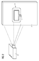
- FIG. 1 shows a first embodiment of a hint according to the invention.
- FIG. 1 shows a projector device 9, which projects on the surface of a test piece 7 resulting from an evaluation hint 11 for the test person on the surface of the test piece 7.
- an inductor 1 is shown in relative position to the test part 7.
- the note 11 according to FIG. 1 is a red field which was projected below the inductor 1 on the test piece 7. The color red indicates to the test person that the inductor 1 is not yet correctly positioned relative to the test piece 7.
- the hint 11 additionally comprises two arrows, one in the x-direction and a z-direction indicating to the examiner how to move the inductor 1 relative to the test piece 7 to achieve a correct relative position.
- the measurement Before an actual measurement, a decision must be made as to which region of the test part 7 the measurement should be performed. Since the geometry of the inductor 1 and its position relative to the test part 7 and all measurement parameters are known, the area around the inductor 1, in which the induction effect comes about, depending on the position of the inductor 1 to the test part 7 can be determined. The position of the inductor 1 relative to the test piece 7 can be determined, for example, by means of a position sensor attached to the inductor 1.
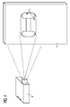
- FIG. 2 shows a second embodiment of a hint according to the invention.
- the inductor 1 has been moved relative to the test part 7 by the test person in accordance with the arrow specifications in the x-direction and z-direction relative to the test part 7.
- the colored field below the inductor 1 now has the color green.
- FIG. 2 shows, for example, a measuring range in which the induction effect comes about. This specific area is projected on the test piece 7 as a green area before the measurement, because now the distance between the inductor 1 and the test piece 7 is correct.
- the measuring position of the inductor 1 relative to the test piece 7 is reached. The measurement can begin.
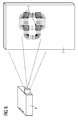
- FIG. 4 shows a fourth embodiment of a hint 11 according to the invention FIG. 4 of the FIG. 3 however, with the difference that after the measurement, color-coded areas are projected onto the examined area, depending on the setting. Even with such a representation according to FIG. 4 can be concluded on the orientation of defects and the area in which they are detectable.
- FIG. 5 shows how the examiner moves the inductor 1 within the same geometry range and moves the projection. This can be a good guess take place, which area of the test part 7 is examined.
- the inductor 1 is rotated 90 degrees by the operator with an activated positioning aid and positioned so that the green surface of the positioning aid partially overlaps with the results of the first measurement.
- the error detection probability increases at the intersection areas, since defects can be made visible regardless of their orientation.
- FIGS. 6 and 7 show further embodiments according to the invention hints 11 for the case of a measurement and an adjoining further measurement. Overlap areas of both measurements are marked green in the projection, both in the line setting and in the area setting. Subsequently, further areas of the test object can be selected and checked. In addition, the inspector may be required to project information about the quality of the positioning of the inductor 1 or a quality of the relative positioning in order to enable a consistent series test of the test parts 7. In this way, the test person can move the inductor 1, for example, until a uniform stored optimum position is reached. In this way it is ensured that with each test part 7 of the series, the inductor 1 is positioned at a same relative position.
- test part 7 For all further measurements, information is displayed cumulatively. If the test person changes the orientation of the inductor 1 during further measurements, for example by 90 degrees, the lines are projected for all measurements. They provide an indication as to which directions of crack have already been covered by measurements already taken with the assumed error detection probability. For further measurements, alternatively or cumulatively, new regions of the test part 7 can be covered with the inductor 1. Information and instructions 11 can be used, for example, as numbers, letters, color fields, Lines or arbitrary symbols can be projected onto the object.
- the invention proposes a method and a device for scanning non-destructive material inspection of a test piece 7, with which the quality of a manual measurement by a test person can be effectively improved. For this purpose, an evaluation of recorded infrared images and the projection of information corresponding to the evaluation 11 are carried out on the test part 7 for the test person.
Description
Die Erfindung betrifft ein Verfahren und eine Vorrichtung zur Induktionsthermografie zur zerstörungsfreien Materialuntersuchung.The invention relates to a method and a device for induction thermography for nondestructive material examination.
Während einer Untersuchung mittels Induktionsthermografie wird ein Prüfkopf, der ebenso als Induktor bezeichnet wird, über einem Prüfling beziehungsweise über ein Prüfteil positioniert. Das aus dem in dem Prüfkopf fließenden Strom resultierende Magnetfeld erzeugt in dem zu untersuchenden Prüfteil einen elektrischen Induktionsstrom. Dieser führt durch Ohmsche Verluste zu einer Erwärmung des Prüfteils. Die in dem Prüfteil resultierende Wärmeverteilung kann wiederum mittels einer Infrarotkamera detektiert werden. Enthält das Prüfteil Defekte, wie es beispielsweise Risse sind, muss der induzierte Strom um diese herum oder über die vorhandenen Berührstellen fließen. Dieser Vorgang führt dazu, dass eine lokale Stromdichte und daraus folgend eine Erwärmung an diesen Stellen erhöht wird. Im Infrarotbild sind damit Risse erkennbar.During an induction thermography study, a test head, also referred to as an inductor, is positioned over a specimen or over a specimen. The magnetic field resulting from the current flowing in the test head generates an electrical induction current in the test part to be examined. This leads by Ohmic losses to a heating of the test piece. The heat distribution resulting in the test part can in turn be detected by means of an infrared camera. If the test piece contains defects, such as cracks, the induced current must flow around them or over the existing contact points. This process causes a local current density and consequent heating at these locations to be increased. Cracks are visible in the infrared image.
Die
Es ist Aufgabe der vorliegenden Erfindung ein Verfahren und eine Vorrichtung der Induktionsthermografie eines Prüfteils anzugeben, mit denen Materialfehler bei nicht automatisierten Messvorgängen mit einer maximalen Fehlerauffindwahrscheinlichkeit erfasst werden. Es sollen alle Materialfehler bestimmter Art, ab einer definierten und bestimmten Größe, im gesamten Prüfteil beziehungsweise in einem bestimmten Bereich des Prüfteils reproduzierbar gefunden werden können.It is the object of the present invention to specify a method and a device for induction thermography of a test part with which material errors in non-automated measuring processes with a maximum probability of error detection are detected. All material defects of a certain kind, starting with a defined and determined size, should be able to be found reproducibly in the entire test piece or in a specific area of the test piece.
Es soll gewährleistet sein, dass die Fehlerauffindwahrscheinlichkeit maximiert wird. Es sollen mittels einer Untersuchung eines Prüfteils, alle Defekte bestimmter Art, wie es beispielsweise Risse sind, ab einer Fehlerauffindwahrscheinlichkeit ist hier als Wahrscheinlichkeitskurve dargestellte Aussage definiert, mit der Wahrscheinlichkeiten der Materialfehlererfassung in Abhängigkeit von der Größe des Materialfehlers und allen relevanten Messparametern beschrieben werden. Die Messparameter können bekannt und/oder direkt oder indirekt eingestellt werden. Messparameter sind insbesondere der Abstand zwischen Induktor und Prüfteil, Größe des Induktionsbereichs im Prüfteil und Richtung des Induktionsstromflusses.It should be ensured that the error detection probability is maximized. It should be by means of an examination of a test part, all defects of a certain kind, such as cracks, from a Error detection probability is defined here as a statement representing probability curve, with which the probabilities of the material error detection as a function of the size of the material error and all relevant measurement parameters are described. The measurement parameters can be known and / or set directly or indirectly. Measuring parameters are, in particular, the distance between the inductor and the test part, the size of the induction region in the test part and the direction of the induction current flow.
Es werden so genannte Fehlerauffindwahrscheinlichkeitskurven (Propability of Detection/POD-Kurven) verwendet, die in Abhängigkeit von der Defektgröße und mit Berücksichtigung aller bedeutenden Messparameter, die Wahrscheinlichkeit der Detektion darstellen. Die Messparameter sind entweder bekannt oder können direkt beziehungsweise indirekt beeinflusst werden. Es kann also eine Aussage getroffen werden, welche minimale Größe ein Defekt aufweisen muss, um mit hinreichender Genauigkeit detektiert zu werden. Diese Aussage ist aber lediglich dann richtig, wenn alle Einschränkungen einer Messung berücksichtigt werden. Wird beispielsweise der Induktor zu weit entfernt von dem Prüfteil durch die Prüfperson gehalten, verändern sich die Messparameter und die Aussage verliert Ihre Gültigkeit.So-called Propability of Detection (POD) curves are used, which represent the probability of detection depending on the defect size and taking into account all significant measurement parameters. The measurement parameters are either known or can be influenced directly or indirectly. Thus, a statement can be made as to which minimum size a defect must have in order to be detected with sufficient accuracy. However, this statement is only correct if all restrictions of a measurement are considered. If, for example, the inductor is held too far away from the test piece by the test person, the measuring parameters change and the statement loses its validity.
Die Aufgabe wird durch ein Verfahren gemäß dem Hauptanspruch und eine Vorrichtung gemäß dem Nebenanspruch gelöst.The object is achieved by a method according to the main claim and a device according to the independent claim.
Gemäß einem ersten Aspekt wird ein Verfahren der scannenden Induktionsthermografie zur zerstörungsfreien Materialuntersuchung eines Prüfteils vorgeschlagen, wobei während einer manuellen Messung durch eine Prüfperson ein Relativpositionieren des Prüfteils und eines eine Infrarotbilder aufzeichnende Infrarotkamera aufweisenden und einen elektrischen Induktionsstrom im Prüfteil erzeugenden Induktors zueinander ausgeführt wird. Es erfolgen eine mittels einer Rechnereinrichtung ausgeführte Auswertung mindestens eines der aufgezeichneten Infrarotbilder und ein mittels einer Projektoreinrichtung auf die Oberfläche des Prüfteils erfolgendes Projizieren jeweils eines einem Ergebnis der Auswertung entsprechenden Hinweises für die Prüfperson.According to a first aspect, there is provided a method of scanning induction thermography for nondestructive material examination of a test piece, wherein during a manual measurement by a test person relative positioning of the test piece and an infrared camera infrared image recording infrared camera and generating an electrical induction current in the test piece generating inductor to each other is performed. An evaluation carried out by means of a computer takes place of at least one of the recorded data Infrared images and projecting by means of a projector device on the surface of the test part in each case one of a result of the evaluation corresponding hint for the test person.
Gemäß einem zweiten Aspekt wird eine Vorrichtung zur scannenden Induktionsthermografie zur zerstörungsfreien Materialuntersuchung eines Prüfteils vorgeschlagen, wobei während einer manuellen Messung durch eine Prüfperson das Prüfteil und ein eine Infrarotbilder aufzeichnende Infrarotkamera aufweisenden und einen elektrischen Induktionsstrom im Prüfteil erzeugender Induktor zueinander relativ positioniert werden, wobei eine mittels einer Rechnereinrichtung ausgeführte Auswertung mindestens eines der aufgezeichneten Infrarotbilder und ein mittels einer Projektoreinrichtung auf die Oberfläche des Prüfteils erfolgendes Projizieren jeweils eines einem Ergebnis der Auswertung entsprechenden Hinweises für die Prüfperson ausgeführt werden.According to a second aspect, an apparatus for scanning induction thermography for nondestructive material examination of a test piece is proposed, wherein during a manual measurement by a test person the test piece and an infrared infrared imaging infrared camera recording and generating an electrical induction current in the test part inducer are relatively positioned relative to each other, a means evaluation of at least one of the recorded infrared images and a projection onto the surface of the test part by means of a projector device are carried out in each case for the test person corresponding to a result of the evaluation.
Es wird also ein System vorgeschlagen, das die Prüfperson während oder nach einer Messung unterstützt, indem wichtige Hinweise direkt auf das Prüfteil projiziert werden. Ziel ist es, der Prüfperson während oder direkt nach der Messung ein Feedback in Form einer Projektion auf das Prüfteil zu geben, das der Prüfperson einen Hinweis darauf gibt, ob die Messung hinsichtlich insbesondere der Fehlerauffindwahrscheinlichkeit, korrekt durchgeführt wird oder wurde. Es ist erkannt worden, dass das Messergebnis einer manuellen nicht automatisierten Induktionsthermografie hinsichtlich der Materialfehlererfassung und ebenso hinsichtlich der Fehlerauffindwahrscheinlichkeit sehr stark von der Prüfperson abhängt (sogenannter menschlicher Aspekt). Erfindungsgemäß werden Informationen aus Infrarotbildern zur Bewertung von Materialfehlern und Abschätzung der Fehlerauffindwahrscheinlichkeit verwendet, um die Prüfperson während oder nach der Messung zu unterstützen und den Einfluss des sogenannten menschlichen Aspektes so weit wie möglich zu verringern.Thus, a system is proposed which assists the test person during or after a measurement by projecting important information directly onto the test piece. The aim is to give the test person during or directly after the measurement a feedback in the form of a projection on the test piece, which gives the test person an indication of whether the measurement is carried out correctly with respect to the error detection probability, in particular. It has been recognized that the measurement result of a manual non-automated induction thermography with respect to the material defect detection and also with respect to the probability of error detection depends very much on the test person (so-called human aspect). According to the invention, information from infrared images is used to evaluate material defects and estimate the probability of error in order to assist the test person during or after the measurement and to reduce the influence of the so-called human aspect as much as possible.
Weitere vorteilhafte Ausgestaltungen werden in Verbindung mit den Unteransprüchen beansprucht.Further advantageous embodiments are claimed in conjunction with the subclaims.
Gemäß einer vorteilhaften Ausgestaltung kann ein Hinweis während oder nach der Messung anzeigen, ob die Messung hinsichtlich einer geforderten Fehlerauffindwahrscheinlichkeit unter Berücksichtigung von Messparametern korrekt ausgeführt wird oder wurde. Es ist erkannt worden, dass folgender Effekt die Fehlerauffindwahrscheinlichkeit beeinflussen kann, und zwar der Abstand zwischen dem Induktor und dem Prüfteil. Ein weiterer Messparameter ergibt sich daraus, dass der induzierte Strom bevorzugt in der Nähe des Induktors beziehungsweise des Prüfkopfes fließt, sodass Fehler lediglich in einem bestimmten Bereich um den Induktor herum detektiert werden können. Dieser Bereich kann als Messbereich bezeichnet werden. Sollte das gesamte Prüfteil beziehungsweise ein größerer Bereich untersucht werden, muss die Messung mehrmals mit entsprechender Verschiebung des Prüfkopfes wiederholt werden. Eine weitere wichtige Erkenntnis ist, dass aufgrund der Richtung des Stromflusses am besten solche Defekte detektiert werden können, die senkrecht zum Stromfluss beziehungsweise zum Induktor liegen. Erfindungsgemäß ist erkannt worden, dass diese Messparameter bei nicht automatisierten Messvorgängen zu Einschränkungen führen können, sodass die Messung fehlerhaft wird und die Fehlerauffindwahrscheinlichkeit zu gering ist. Mittels der Projektion der jeweiligen Fehlerauffindwahrscheinlichkeit an die Prüfperson kann die Fehlerauffindwahrscheinlichkeit bei der Messung über das gesamte Prüfteil beziehungsweise mehrere Prüfteile konstant gehalten werden. Dies ist ein großer Vorteil bei Messungen, bei denen eine Automatisierung entweder nicht möglich oder nicht rentabel wäre.According to an advantageous embodiment, an indication during or after the measurement can indicate whether the measurement with respect to a required error detection probability taking into account measurement parameters is or will be performed correctly. It has been recognized that the following effect can affect the probability of error detection, namely the distance between the inductor and the test piece. Another measurement parameter results from the fact that the induced current preferably flows in the vicinity of the inductor or the test head, so that errors can only be detected in a certain area around the inductor. This area can be called a measuring area. If the entire test piece or a larger area is to be examined, the measurement must be repeated several times with appropriate displacement of the test head. Another important finding is that due to the direction of the current flow, it is best to detect defects that are perpendicular to the current flow or to the inductor. According to the invention, it has been recognized that these measurement parameters can lead to limitations in non-automated measurement processes, so that the measurement becomes erroneous and the error detection probability is too low. By means of the projection of the respective error detection probability to the test person, the probability of error finding can be kept constant during the measurement over the entire test part or several test parts. This is a great advantage in measurements where automation would either be impossible or not profitable.
Gemäß einer weiteren vorteilhaften Ausgestaltung kann die Rechnereinrichtung mittels von der zu erfassenden Größe eines Materialfehlers abhängigen Fehlerauffindwahrscheinlichkeitskurven unter Berücksichtigung der Messparameter, das heißt die Eigenschaften unter denen die Messung erfolgt, die maximale mögliche Fehlerauffindwahrscheinlichkeit der Messung bestimmen.According to a further advantageous refinement, the computer device can determine the maximum error detection curves dependent on the size of a material defect to be detected, taking into account the measurement parameters, that is to say the properties under which the measurement takes place determine possible error detection probability of the measurement.
Gemäß einer weiteren vorteilhaften Ausgestaltung kann die Rechnereinrichtung die Auswertung mindestens eines der aufgezeichneten Infrarotbilder zur Berechnung der Messparameter der Messung ausführen.According to a further advantageous embodiment, the computer device can perform the evaluation of at least one of the recorded infrared images for the calculation of the measurement parameters of the measurement.
Gemäß einer weiteren vorteilhaften Ausgestaltung kann zur Berechnung von Messparametern die Auswertung des Infrarotbildes des Prüfteils ohne Induktor ausgeführt werden.According to a further advantageous embodiment, the evaluation of the infrared image of the test part can be performed without inductor for the calculation of measurement parameters.
Gemäß einer weiteren vorteilhaften Ausgestaltung kann zur Berechnung von Messparametern die Auswertung eines vor der Induktion des Induktionsstromes aufgenommenen Infrarotbildes des positionierten Induktors und des Prüfteils ausgeführt werden.According to a further advantageous embodiment, the evaluation of a captured before the induction of the induction current infrared image of the positioned inductor and the test part can be performed to calculate measurement parameters.
Gemäß einer weiteren vorteilhaften Ausgestaltung kann zur Berechnung von Messparametern die Auswertung eines mittels Puls-Phasen-Analyse der während der Messung aufgenommenen Infrarotbilder erzeugten Amplitudenbildes ausgeführt werden.According to a further advantageous embodiment, the evaluation of an amplitude image generated by means of pulse-phase analysis of the infrared images recorded during the measurement can be carried out for the calculation of measurement parameters.
Gemäß einer weiteren vorteilhaften Ausgestaltung kann zur Berechnung von Messparametern die Auswertung eines mittels Puls-Phasen-Analyse der während der Messung aufgenommen Infrarotbilder erzeugten Phasenbildes ausgeführt werden.According to a further advantageous embodiment, the evaluation of a phase image generated by means of pulse-phase analysis of the infrared images taken during the measurement can be carried out for the calculation of measurement parameters.
Gemäß einer weiteren vorteilhaften Ausgestaltung können die Messparameter der Abstand zwischen Induktor und Prüfteil, der Messbereich des Induktors und/oder die Orientierung des Induktors gegenüber dem Prüfteil sein.According to a further advantageous embodiment, the measurement parameters may be the distance between the inductor and the test piece, the measuring range of the inductor and / or the orientation of the inductor relative to the test piece.
Gemäß einer weiteren vorteilhaften Ausgestaltung kann als ein Hinweis während oder nach der Messung senkrecht zur Orientierung des Induktors verlaufende Linien auf das Prüfteil projiziert werden zur Anzeige, dass entlang der Linien sich erstreckende Materialfehler mit einer maximalen möglichen Fehlerauffindwahrscheinlichkeit erfasst werden oder wurden.According to a further advantageous embodiment, as a reference during or after the measurement perpendicular to the orientation of the inductor extending lines can be projected onto the test piece to indicate that along the lines extending Material errors with a maximum possible probability of error detection were or were recorded.
Gemäß einer weiteren vorteilhaften Ausgestaltung können als ein Hinweis während oder nach der Messung farbkodierte Flächen auf das Prüfteil projiziert werden, zur Anzeige, dass in den jeweiligen Farbflächen sich in bestimmte Richtungen sich erstreckende Materialfehler mit einer maximalen Fehlerauffindwahrscheinlichkeit werden oder wurden.According to a further advantageous embodiment, as an indication during or after the measurement, color-coded areas can be projected onto the test piece in order to indicate that in the respective color areas material defects extending in certain directions have become or became a maximum error probability.
Gemäß einer weiteren vorteilhaften Ausgestaltung kann nach der Messung die Orientierung des Induktors verändert und eine weitere Messung ausgeführt werden, wobei zusätzlich weitere senkrecht zur veränderten Orientierung des Induktors verlaufende Linien und weitere Farbcodierte Flächen auf das Prüfteil projiziert werden können.According to a further advantageous embodiment, after the measurement, the orientation of the inductor can be changed and a further measurement can be carried out, wherein in addition further perpendicular to the changed orientation of the inductor extending lines and other color-coded surfaces can be projected onto the test piece.
Gemäß einer weiteren vorteilhaften Ausgestaltung kann ein Hinweis während oder nach der Messung angezeigt werden, ob bei Bekanntsein der Geometrie des Induktors dessen Lage gegenüber dem Prüfteil und aller Messparameter, die Messparameter der Messung korrekt eingestellt sind oder waren.According to a further advantageous embodiment, an indication can be displayed during or after the measurement, if, when the geometry of the inductor is known, its position relative to the test part and all measurement parameters, the measurement parameters of the measurement are or have been set correctly.
Gemäß einer weiteren vorteilhaften Ausgestaltung kann ein Hinweis den Messbereich des Induktors in Abhängigkeit von dessen Relativposition zum Prüfteil als farbige Fläche auf dem Prüfteil anzeigen.According to a further advantageous embodiment, an indication can indicate the measuring range of the inductor as a function of its relative position to the test part as a colored area on the test part.
Gemäß einer weiteren vorteilhaften Ausgestaltung kann ein Hinweis während oder nach der Messung die Korrektheit des Abstandes zwischen Induktor und Prüfteil mittels einer bestimmten Farbe der farbigen Fläche anzeigen.According to a further advantageous refinement, an indication during or after the measurement can indicate the correctness of the distance between the inductor and the test part by means of a specific color of the colored area.
Gemäß einer weiteren vorteilhaften Ausgestaltung können gleiche Messbereiche von Messungen mit unterschiedlichen Orientierungen des Induktors überlappend angezeigt werden.According to a further advantageous embodiment, the same measuring ranges of measurements with different orientations of the inductor can be displayed overlapping.
Gemäß einer weiteren vorteilhaften Ausgestaltung kann ein Hinweis eine Information zur Qualität der Positionierung des Induktors anzeigen.According to a further advantageous embodiment, an indication may indicate information about the quality of the positioning of the inductor.
Die Erfindung wird anhand von Ausführungsbeispielen in Verbindung mit den Figuren näher beschrieben. Es zeigen:
Figur 1- ein erstes Ausführungsbeispiel eines erfindungsgemäßen Hinweises;
- Figur 2
- ein zweites Ausführungsbeispiel eines erfindungsgemäßen Hinweises;
- Figur 3
- ein drittes Ausführungsbeispiel eines erfindungemäßen Hinweises;
- Figur 4
- ein viertes Ausführungsbeispiel eines erfindungsgemäßen Hinweises;
- Figur 5
- ein Ausführungsbeispiel einer weiteren Messung;
- Figur 6
- ein fünftes Ausführungsbeispiel eines erfindungsgemäßen Hinweises;
Figur 7- ein sechstes Ausführungsbeispiel eines erfindungsgemäßen Hinweises.
- FIG. 1
- a first embodiment of a hint according to the invention;
- FIG. 2
- A second embodiment of an indication according to the invention;
- FIG. 3
- a third embodiment of a erfindungemäßen hint;
- FIG. 4
- A fourth embodiment of a hint according to the invention;
- FIG. 5
- an embodiment of another measurement;
- FIG. 6
- A fifth embodiment of a hint according to the invention;
- FIG. 7
- A sixth embodiment of an indication according to the invention.
- 1. Die x,y-Position des
Induktors 1 unter Verwendung der Bilder "O" und "I" mit einer Differenzbildung Ix'=(1-O). - 2. Bereich, der vom Induktor 1 verdeckt wurde, unter Verwendung der Bilder "O" und "I" unter Verwendung des Algorithmus

- 3. Bereich, in dem der Induktionseffekt eine ausreichende Stärke hatte, wobei ebenso schief oder in falschem Abstand gehaltene Induktoren 1 berücksichtigt sind, unter Verwendung des Bildes "A" mittels des Algorithmus
- 1. Maskierung des Induktors Ax' = A * I';
- 2. Umrechnung des Amplitudenbildes Ax' in ein Temperaturdifferenzbild T;
- 3. Umwandlung in eine farbkodierte Darstellung der Fehlerauffindwahrscheinlichkeit F beziehungsweise des Kontrasts/Signal-Rausch-Verhältnisses.
- 4. Orientierungssensitivität, unter Verwendung der Bilder "A" und "P", mittels
- 1. Extraktion der Linien gleicher Richtung des Stromflusses, den sogenannten "Höhenlinien";
- 2. Berechnung der Senkrechten dieser Höhenlinien, wobei diese Linien der optimalen Defektorientierung entsprechen, das heißt der Ausrichtung, in der Risse am besten erkannt werden können. Wird
beispielsweise als Induktor 1 eine runde Leiterschleife verwendet, ist die Orientierungssensitivität ein Strahlenkranzum den Induktor 1.
- 5. z-Position des
Induktors 1, und zwar der Abstand Induktor 1 -Prüfteil 7, unter Verwendung des Bildes "A" mittels Vergleichen des Amplitudenverlaufs in der Nähe desInduktors 1 mit analytisch berechneten Lösungen.
- 1. The x, y position of the
inductor 1 using the images "O" and "I" with a difference Ix ' = ( 1 - O ). - 2. Area obscured by the
inductor 1 using the images "O" and "I" using the algorithm - 3. Region in which the induction effect had sufficient strength, taking into account skewed or spaced
inductors 1 as well, using the image "A" by the algorithm- 1. Masking of the inductor Ax ' = A * I' ;
- 2. conversion of the amplitude image Ax 'into a temperature difference image T ;
- 3. Conversion to a color-coded representation of the error detection probability F or the contrast / signal-to-noise ratio.
- 4. Orientation sensitivity, using the images "A" and "P", by means of
- 1. extraction of the lines of the same direction of current flow, the so-called "contour lines";
- 2. Calculation of the vertical lines of these contour lines, these lines corresponding to the optimal Defektorientierung, that is, the orientation in which cracks can be best recognized. If, for example, a round conductor loop is used as the
inductor 1, the orientation sensitivity is a halo around theinductor 1.
- 5. z position of the
inductor 1, namely the distance inductor 1 -test part 7, using the image "A" by comparing the amplitude curve in the vicinity of theinductor 1 with analytically calculated solutions.
Anschließend kann beurteilt werden, ob die Fehlerauffindwahrscheinlichkeit in dem untersuchten Bereich mit der Forderung übereinstimmt und diese Information auf das Prüfteil 7 projiziert wird. Dabei ist zu berücksichtigen, dass die Detektierbarkeit, und die Fehlerauffindwahrscheinlichkeit stark von der Orientierung des Prüfkopfes beziehungsweise des Induktors 1 gegenüber potentiellen Defekten abhängt. Dies muss in der Projektion zum Ausdruck gebracht werden. Gemäß
Für alle weiteren Messungen werden Informationen kumulativ dargestellt. Ändert die Prüfperson die Orientierung des Induktors 1 bei weiteren Messungen beispielsweise um 90 Grad, werden für alle Messungen die Linien projiziert. Sie geben einen Hinweis darauf, welche Rissrichtungen von bereits durchgeführten Messungen mit der angenommenen Fehlerauffindwahrscheinlichkeit abgedeckt wurden. Für weitere Messungen können alternativ oder kumulativ neue Bereiche des Prüfteils 7 mit dem Induktor 1 abgedeckt werden. Informationen und Hinweise 11 können beispielsweise als Zahlen, Buchstaben, Farbfelder, Linien oder beliebige Symbole auf das Objekt projiziert sein.For all further measurements, information is displayed cumulatively. If the test person changes the orientation of the
Die Erfindung schlägt ein Verfahren und eine Vorrichtung zur scannenden Induktionsthermografie zur zerstörungsfreien Materialuntersuchung eines Prüfteils 7 vor, mit denen die Qualität einer manuellen Messung durch eine Prüfperson wirksam verbessert werden kann. Dazu werden eine Auswertung von aufgezeichneten Infrarotbildern und das Projizieren von der Auswertung entsprechenden Hinweisen 11 auf das Prüfteil 7 für die Prüfperson ausgeführt.The invention proposes a method and a device for scanning non-destructive material inspection of a
Claims (32)
- Method for scanning induction thermography for nondestructive material examination of a test specimen (7), in which the test specimen (7) and an inductor (1) which has an infrared camera (5), which records infrared images, and generates an electric induction current in the test specimen (7) are positioned relative to one another by a testing technician during a manual measurement, wherein an evaluation, carried out by means of a computer device, of at least one of the recorded infrared images, and a projection, performed by means of a projector device (9) onto the surface of the test specimen (7), of in each case one indication (11) for the testing technician which corresponds to a result of the evaluation are carried out, characterized in that an indication during or after the measurement indicates whether the measurement is or has been carried out correctly in respect of a required defect detection probability, taking account of measurement parameters.
- Method according to Claim 1, characterized in that the computer device determines the defect detection probability of the measurement by means of defect detection probability curves depending on the magnitude, which is to be acquired, of a material defect while taking account of the measurement parameters.
- Method according to Claim 1 or 2, characterized in that the computer device carries out the evaluation of at least one of the recorded infrared images in order to calculate the measurement parameters of the measurement.
- Method according to Claim 3, characterized in that the evaluation of an infrared image (0) of the test specimen (7) is carried out without an inductor in order to calculate measurement parameters.
- Method according to Claim 3 or 4, characterized in that in order to calculate measurement parameters the evaluation of an infrared image (I), recorded before the induction of the induction current, of the positioned inductor and of the test specimen (7) is carried out.
- Method according to Claim 3, 4 or 5, characterized in that in order to calculate measurement parameters the evaluation of an amplitude image (A) generated by means of pulse-phase analysis of the infrared images recorded during the measurement is carried out.
- Method according to Claim 3, 4, 5 or 6, characterized in that in order to calculate measurement parameters the evaluation of a phase image (P) generated by means of pulse-phase analysis of the infrared images recorded during the measurement is carried out.
- Method according to one of the preceding Claims 1 to 7, characterized in that measurement parameter(s) is/are the distance between inductor and test specimen, the measurement range of the inductor and/or the orientation of the inductor with respect to the test specimen.
- Method according to Claim 8, characterized in that as an indication lines running perpendicular to the orientation of the inductor are projected onto the test specimen during or after the measurement in order to indicate that material defects extending along the lines are or have been acquired with a maximum defect detection probability.
- Method according to Claim 8, characterized in that as an indication color-coded areas are projected onto the test specimen during or after the measurement in order to indicate that material defects extending in specific directions in the respective colored areas are or have been acquired with a maximum defect detection probability.
- Method according to Claim 9 or 10, characterized in that the orientation of the inductor is changed after the measurement and a further measurement is carried out, further lines running perpendicular to the changed orientation of the inductor or further color-coded areas additionally being projected onto the test specimen.
- Method according to one of the preceding claims, characterized in that an indication during or after the measurement indicates whether the measurement parameters of the measurement are or have been correctly set, given that the geometry of the inductor, the position of the latter with respect to the test specimen, and all the measurement parameters are known.
- Method according to Claim 12, characterized in that an indication indicates the measurement range of the inductor as a colored area on the test specimen as a function of the position of said inductor relative to the test specimen.
- Method according to Claim 12 or 13, characterized in that an indication indicates the correctness of the distance between inductor and test specimen during or after the measurement by means of a specific color of the colored area.
- Method according to Claim 13, characterized in that identical measurement ranges of measurements with different orientations of the inductor are indicated in an overlapping fashion.
- Method according to one of the preceding claims, characterized in that an indication indicates an information item relating to the quality of the positioning of the inductor.
- Device for scanning induction thermography for nondestructive material examination of a test specimen (7), in which the test specimen (7) and an inductor (1) which has an infrared camera (5), which records infrared images, and generates an electric induction current in the test specimen (7) are positioned relative to one another by a testing technician during a manual measurement, wherein an evaluation, carried out by means of a computer device, of at least one of the recorded infrared images, and a projection, performed by means of a projector device (9) onto the surface of the test specimen (7), of in each case one indication (11) for the testing technician which corresponds to a result of the evaluation can be carried out, characterized in that an indication during or after the measurement indicates whether the measurement is or has been carried out correctly in respect of a required defect detection probability, taking account of measurement parameters.
- Device according to Claim 17, characterized in that the computer device determines the defect detection probability of the measurement by means of defect detection probability curves depending on the magnitude, which is to be acquired, of a material defect while taking account of the measurement parameters.
- Device according to Claim 17 or 18, characterized in that the computer device carries out the evaluation of at least one of the recorded infrared images in order to calculate the measurement parameters of the measurement.
- Device according to Claim 19, characterized in that the evaluation of an infrared image (0) of the test specimen (7) is carried out without an inductor in order to calculate measurement parameters.
- Device according to Claim 19 or 20, characterized in that in order to calculate measurement parameters the evaluation of an infrared image (I), recorded before the induction of the induction current, of the positioned inductor and of the test specimen (7) is carried out.
- Device according to Claim 19, 20 or 21, characterized in that in order to calculate measurement parameters the evaluation of an amplitude image (A) generated by means of pulse-phase analysis of the infrared images recorded during the measurement is carried out.
- Device according to Claim 19, 20, 21 or 22, characterized in that in order to calculate measurement parameters the evaluation of a phase image (P) generated by means of pulse-phase analysis of the infrared images recorded during the measurement is carried out.
- Device according to one of the preceding Claims 17 to 23, characterized in that measurement parameter(s) is/are the distance between inductor and test specimen, the measurement range of the inductor and/or the orientation of the inductor with respect to the test specimen.
- Device according to Claim 24, characterized in that as an indication lines running perpendicular to the orientation of the inductor are projected onto the test specimen during or after the measurement in order to indicate that material defects extending along the lines are or have been acquired with a maximum defect detection probability.
- Device according to Claim 24, characterized in that as an indication color-coded areas are projected onto the test specimen during or after the measurement in order to indicate that material defects extending in specific directions in the respective colored areas are or have been acquired with a maximum defect detection probability.
- Device according to Claim 25 or 26, characterized in that the orientation of the inductor is changed after the measurement and a further measurement is carried out, further lines running perpendicular to the changed orientation of the inductor or further color-coded areas additionally being projected onto the test specimen.
- Device according to one of the preceding Claims 16 to 27, characterized in that an indication during or after the measurement indicates whether the measurement parameters of the measurement are or have been correctly set, given that the geometry of the inductor, the position of the latter with respect to the test specimen, and all the measurement parameters are known.
- Device according to Claim 28, characterized in that an indication indicates the measurement range of the inductor as a colored area on the test specimen as a function of the position of said inductor relative to the test specimen.
- Device according to Claim 28 or 29, characterized in that an indication indicates the correctness of the distance between inductor and test specimen during or after the measurement by means of a specific color of the colored area.
- Device according to Claim 29, characterized in that identical measurement ranges of measurements with different orientations of the inductor are indicated in an overlapping fashion.
- Device according to one of the preceding Claims 16 to 31, characterized in that an indication indicates an information item relating to the quality of the positioning of the inductor.
Applications Claiming Priority (2)
| Application Number | Priority Date | Filing Date | Title |
|---|---|---|---|
| DE102012212434.9A DE102012212434A1 (en) | 2012-07-16 | 2012-07-16 | Visualization of indications in induction thermography |
| PCT/EP2013/062098 WO2014012716A1 (en) | 2012-07-16 | 2013-06-12 | Visualization of references during induction thermography |
Publications (2)
| Publication Number | Publication Date |
|---|---|
| EP2812656A1 EP2812656A1 (en) | 2014-12-17 |
| EP2812656B1 true EP2812656B1 (en) | 2016-11-16 |
Family
ID=48670509
Family Applications (1)
| Application Number | Title | Priority Date | Filing Date |
|---|---|---|---|
| EP13730512.4A Not-in-force EP2812656B1 (en) | 2012-07-16 | 2013-06-12 | Visualization of references during induction thermography |
Country Status (4)
| Country | Link |
|---|---|
| US (1) | US20150134273A1 (en) |
| EP (1) | EP2812656B1 (en) |
| DE (1) | DE102012212434A1 (en) |
| WO (1) | WO2014012716A1 (en) |
Families Citing this family (1)
| Publication number | Priority date | Publication date | Assignee | Title |
|---|---|---|---|---|
| DE102014202128A1 (en) * | 2014-02-06 | 2015-08-06 | Siemens Aktiengesellschaft | inductor |
Family Cites Families (4)
| Publication number | Priority date | Publication date | Assignee | Title |
|---|---|---|---|---|
| DE10049926A1 (en) * | 2000-10-07 | 2002-04-11 | Robert Massen | Camera for photogrammetric detection of shape of limb has projector attachment for providing visually detectable alignment structures |
| DE102010007449B4 (en) * | 2010-02-10 | 2013-02-28 | Siemens Aktiengesellschaft | Arrangement and method for evaluating a test object by means of active thermography |
| DE102010014744B4 (en) * | 2010-04-13 | 2013-07-11 | Siemens Aktiengesellschaft | Apparatus and method for projecting information onto an object in thermographic surveys |
| DE102011086267A1 (en) * | 2011-11-14 | 2013-05-16 | Siemens Aktiengesellschaft | System and method for controlling a thermographic measuring process |
-
2012
- 2012-07-16 DE DE102012212434.9A patent/DE102012212434A1/en not_active Ceased
-
2013
- 2013-06-12 US US14/401,472 patent/US20150134273A1/en not_active Abandoned
- 2013-06-12 EP EP13730512.4A patent/EP2812656B1/en not_active Not-in-force
- 2013-06-12 WO PCT/EP2013/062098 patent/WO2014012716A1/en active Application Filing
Non-Patent Citations (1)
| Title |
|---|
| None * |
Also Published As
| Publication number | Publication date |
|---|---|
| DE102012212434A1 (en) | 2014-01-16 |
| WO2014012716A1 (en) | 2014-01-23 |
| US20150134273A1 (en) | 2015-05-14 |
| EP2812656A1 (en) | 2014-12-17 |
Similar Documents
| Publication | Publication Date | Title |
|---|---|---|
| EP2375243B1 (en) | Thermographic testing method and device for carrying out the testing method | |
| DE102016124522A1 (en) | Method of inspecting a steel strip | |
| EP3161472A1 (en) | Method and device for stray flow testing | |
| WO2011085935A1 (en) | Test device for determining the quality of leather | |
| WO2006007807A1 (en) | Method and device for testing pipes in a non-destructive manner | |
| DE102007026540A1 (en) | Sample surface testing method, involves comparing data obtained for test sample with sample data, and testing condition of internal stress produced in test sample based on condition of internal stress of test sample | |
| EP2286212A1 (en) | Method for the nondestructive testing of pipes | |
| DE102008017267B4 (en) | Methods and algorithms for checking longitudinal defects in an eddy current checking system | |
| DE102012112121B4 (en) | Method and device for non-destructive testing of a rotationally symmetrical workpiece which has sections of different diameters | |
| DE102009038746B3 (en) | Method and apparatus for quality testing a reshaped thermoplastic fiber reinforced plastic component | |
| EP2812656B1 (en) | Visualization of references during induction thermography | |
| DE102014221558A1 (en) | Method for non-destructive testing of a component | |
| DE102006019128A1 (en) | Device for detecting defects on metal parts | |
| DE3339661C2 (en) | ||
| WO2012059445A1 (en) | Method and evaluation device for determining the position of a structure located in an object to be examined by means of x-ray computer tomography | |
| DE19542554A1 (en) | Welded seams testing method for workpiece using triangulation sensor | |
| EP3904867B1 (en) | Method and device for determining the break area of a sample | |
| DE102018219722B3 (en) | METHOD FOR CHECKING A MAGNETIC FIELD SOURCE | |
| DE102011089856A1 (en) | Inspection of a test object | |
| EP3008458B1 (en) | Induction thermography method | |
| EP1052505A1 (en) | Methode of analysing the surface of an object comprising at least one electrically conductive layer | |
| EP3586307A1 (en) | Method and device for detecting corners | |
| DE102008052983A1 (en) | Eddy current sensor and method for determining due to thermal influences modified material properties in a component to be examined by means of the same | |
| DE102015004607A1 (en) | Sensor unit, system and method for detecting and locating anomalies in test objects of electrically conductive material | |
| DE102020210684A1 (en) | Method for spatially resolved testing of a property of a wall and testing device |
Legal Events
| Date | Code | Title | Description |
|---|---|---|---|
| PUAI | Public reference made under article 153(3) epc to a published international application that has entered the european phase |
Free format text: ORIGINAL CODE: 0009012 |
|
| 17P | Request for examination filed |
Effective date: 20140912 |
|
| AK | Designated contracting states |
Kind code of ref document: A1 Designated state(s): AL AT BE BG CH CY CZ DE DK EE ES FI FR GB GR HR HU IE IS IT LI LT LU LV MC MK MT NL NO PL PT RO RS SE SI SK SM TR |
|
| AX | Request for extension of the european patent |
Extension state: BA ME |
|
| DAX | Request for extension of the european patent (deleted) | ||
| GRAP | Despatch of communication of intention to grant a patent |
Free format text: ORIGINAL CODE: EPIDOSNIGR1 |
|
| INTG | Intention to grant announced |
Effective date: 20160608 |
|
| GRAJ | Information related to disapproval of communication of intention to grant by the applicant or resumption of examination proceedings by the epo deleted |
Free format text: ORIGINAL CODE: EPIDOSDIGR1 |
|
| GRAP | Despatch of communication of intention to grant a patent |
Free format text: ORIGINAL CODE: EPIDOSNIGR1 |
|
| INTC | Intention to grant announced (deleted) | ||
| INTG | Intention to grant announced |
Effective date: 20160907 |
|
| GRAS | Grant fee paid |
Free format text: ORIGINAL CODE: EPIDOSNIGR3 |
|
| GRAA | (expected) grant |
Free format text: ORIGINAL CODE: 0009210 |
|
| AK | Designated contracting states |
Kind code of ref document: B1 Designated state(s): AL AT BE BG CH CY CZ DE DK EE ES FI FR GB GR HR HU IE IS IT LI LT LU LV MC MK MT NL NO PL PT RO RS SE SI SK SM TR |
|
| REG | Reference to a national code |
Ref country code: GB Ref legal event code: FG4D Free format text: NOT ENGLISH |
|
| REG | Reference to a national code |
Ref country code: CH Ref legal event code: EP |
|
| REG | Reference to a national code |
Ref country code: IE Ref legal event code: FG4D Free format text: LANGUAGE OF EP DOCUMENT: GERMAN |
|
| REG | Reference to a national code |
Ref country code: AT Ref legal event code: REF Ref document number: 846355 Country of ref document: AT Kind code of ref document: T Effective date: 20161215 |
|
| REG | Reference to a national code |
Ref country code: DE Ref legal event code: R096 Ref document number: 502013005390 Country of ref document: DE |
|
| PG25 | Lapsed in a contracting state [announced via postgrant information from national office to epo] |
Ref country code: LV Free format text: LAPSE BECAUSE OF FAILURE TO SUBMIT A TRANSLATION OF THE DESCRIPTION OR TO PAY THE FEE WITHIN THE PRESCRIBED TIME-LIMIT Effective date: 20161116 |
|
| REG | Reference to a national code |
Ref country code: NL Ref legal event code: MP Effective date: 20161116 |
|
| REG | Reference to a national code |
Ref country code: LT Ref legal event code: MG4D |
|
| PG25 | Lapsed in a contracting state [announced via postgrant information from national office to epo] |
Ref country code: SE Free format text: LAPSE BECAUSE OF FAILURE TO SUBMIT A TRANSLATION OF THE DESCRIPTION OR TO PAY THE FEE WITHIN THE PRESCRIBED TIME-LIMIT Effective date: 20161116 Ref country code: NO Free format text: LAPSE BECAUSE OF FAILURE TO SUBMIT A TRANSLATION OF THE DESCRIPTION OR TO PAY THE FEE WITHIN THE PRESCRIBED TIME-LIMIT Effective date: 20170216 Ref country code: NL Free format text: LAPSE BECAUSE OF FAILURE TO SUBMIT A TRANSLATION OF THE DESCRIPTION OR TO PAY THE FEE WITHIN THE PRESCRIBED TIME-LIMIT Effective date: 20161116 Ref country code: LT Free format text: LAPSE BECAUSE OF FAILURE TO SUBMIT A TRANSLATION OF THE DESCRIPTION OR TO PAY THE FEE WITHIN THE PRESCRIBED TIME-LIMIT Effective date: 20161116 Ref country code: GR Free format text: LAPSE BECAUSE OF FAILURE TO SUBMIT A TRANSLATION OF THE DESCRIPTION OR TO PAY THE FEE WITHIN THE PRESCRIBED TIME-LIMIT Effective date: 20170217 |
|
| PG25 | Lapsed in a contracting state [announced via postgrant information from national office to epo] |
Ref country code: ES Free format text: LAPSE BECAUSE OF FAILURE TO SUBMIT A TRANSLATION OF THE DESCRIPTION OR TO PAY THE FEE WITHIN THE PRESCRIBED TIME-LIMIT Effective date: 20161116 Ref country code: PL Free format text: LAPSE BECAUSE OF FAILURE TO SUBMIT A TRANSLATION OF THE DESCRIPTION OR TO PAY THE FEE WITHIN THE PRESCRIBED TIME-LIMIT Effective date: 20161116 Ref country code: PT Free format text: LAPSE BECAUSE OF FAILURE TO SUBMIT A TRANSLATION OF THE DESCRIPTION OR TO PAY THE FEE WITHIN THE PRESCRIBED TIME-LIMIT Effective date: 20170316 Ref country code: RS Free format text: LAPSE BECAUSE OF FAILURE TO SUBMIT A TRANSLATION OF THE DESCRIPTION OR TO PAY THE FEE WITHIN THE PRESCRIBED TIME-LIMIT Effective date: 20161116 Ref country code: HR Free format text: LAPSE BECAUSE OF FAILURE TO SUBMIT A TRANSLATION OF THE DESCRIPTION OR TO PAY THE FEE WITHIN THE PRESCRIBED TIME-LIMIT Effective date: 20161116 Ref country code: FI Free format text: LAPSE BECAUSE OF FAILURE TO SUBMIT A TRANSLATION OF THE DESCRIPTION OR TO PAY THE FEE WITHIN THE PRESCRIBED TIME-LIMIT Effective date: 20161116 |
|
| PG25 | Lapsed in a contracting state [announced via postgrant information from national office to epo] |
Ref country code: EE Free format text: LAPSE BECAUSE OF FAILURE TO SUBMIT A TRANSLATION OF THE DESCRIPTION OR TO PAY THE FEE WITHIN THE PRESCRIBED TIME-LIMIT Effective date: 20161116 Ref country code: RO Free format text: LAPSE BECAUSE OF FAILURE TO SUBMIT A TRANSLATION OF THE DESCRIPTION OR TO PAY THE FEE WITHIN THE PRESCRIBED TIME-LIMIT Effective date: 20161116 Ref country code: DK Free format text: LAPSE BECAUSE OF FAILURE TO SUBMIT A TRANSLATION OF THE DESCRIPTION OR TO PAY THE FEE WITHIN THE PRESCRIBED TIME-LIMIT Effective date: 20161116 Ref country code: SK Free format text: LAPSE BECAUSE OF FAILURE TO SUBMIT A TRANSLATION OF THE DESCRIPTION OR TO PAY THE FEE WITHIN THE PRESCRIBED TIME-LIMIT Effective date: 20161116 Ref country code: CZ Free format text: LAPSE BECAUSE OF FAILURE TO SUBMIT A TRANSLATION OF THE DESCRIPTION OR TO PAY THE FEE WITHIN THE PRESCRIBED TIME-LIMIT Effective date: 20161116 |
|
| REG | Reference to a national code |
Ref country code: DE Ref legal event code: R097 Ref document number: 502013005390 Country of ref document: DE |
|
| RAP2 | Party data changed (patent owner data changed or rights of a patent transferred) |
Owner name: SIEMENS AKTIENGESELLSCHAFT |
|
| PG25 | Lapsed in a contracting state [announced via postgrant information from national office to epo] |
Ref country code: IT Free format text: LAPSE BECAUSE OF FAILURE TO SUBMIT A TRANSLATION OF THE DESCRIPTION OR TO PAY THE FEE WITHIN THE PRESCRIBED TIME-LIMIT Effective date: 20161116 Ref country code: SM Free format text: LAPSE BECAUSE OF FAILURE TO SUBMIT A TRANSLATION OF THE DESCRIPTION OR TO PAY THE FEE WITHIN THE PRESCRIBED TIME-LIMIT Effective date: 20161116 Ref country code: BG Free format text: LAPSE BECAUSE OF FAILURE TO SUBMIT A TRANSLATION OF THE DESCRIPTION OR TO PAY THE FEE WITHIN THE PRESCRIBED TIME-LIMIT Effective date: 20170216 |
|
| PLBE | No opposition filed within time limit |
Free format text: ORIGINAL CODE: 0009261 |
|
| STAA | Information on the status of an ep patent application or granted ep patent |
Free format text: STATUS: NO OPPOSITION FILED WITHIN TIME LIMIT |
|
| REG | Reference to a national code |
Ref country code: CH Ref legal event code: NV Representative=s name: SIEMENS SCHWEIZ AG, CH Ref country code: CH Ref legal event code: PCOW Free format text: NEW ADDRESS: WERNER-VON-SIEMENS-STRASSE 1, 80333 MUENCHEN (DE) |
|
| 26N | No opposition filed |
Effective date: 20170817 |
|
| PG25 | Lapsed in a contracting state [announced via postgrant information from national office to epo] |
Ref country code: SI Free format text: LAPSE BECAUSE OF FAILURE TO SUBMIT A TRANSLATION OF THE DESCRIPTION OR TO PAY THE FEE WITHIN THE PRESCRIBED TIME-LIMIT Effective date: 20161116 |
|
| REG | Reference to a national code |
Ref country code: DE Ref legal event code: R119 Ref document number: 502013005390 Country of ref document: DE |
|
| PG25 | Lapsed in a contracting state [announced via postgrant information from national office to epo] |
Ref country code: MC Free format text: LAPSE BECAUSE OF FAILURE TO SUBMIT A TRANSLATION OF THE DESCRIPTION OR TO PAY THE FEE WITHIN THE PRESCRIBED TIME-LIMIT Effective date: 20161116 |
|
| REG | Reference to a national code |
Ref country code: CH Ref legal event code: PL |
|
| GBPC | Gb: european patent ceased through non-payment of renewal fee |
Effective date: 20170612 |
|
| REG | Reference to a national code |
Ref country code: IE Ref legal event code: MM4A |
|
| REG | Reference to a national code |
Ref country code: FR Ref legal event code: ST Effective date: 20180228 |
|
| PG25 | Lapsed in a contracting state [announced via postgrant information from national office to epo] |
Ref country code: IE Free format text: LAPSE BECAUSE OF NON-PAYMENT OF DUE FEES Effective date: 20170612 Ref country code: CH Free format text: LAPSE BECAUSE OF NON-PAYMENT OF DUE FEES Effective date: 20170630 Ref country code: LU Free format text: LAPSE BECAUSE OF NON-PAYMENT OF DUE FEES Effective date: 20170612 Ref country code: DE Free format text: LAPSE BECAUSE OF NON-PAYMENT OF DUE FEES Effective date: 20180103 Ref country code: GB Free format text: LAPSE BECAUSE OF NON-PAYMENT OF DUE FEES Effective date: 20170612 Ref country code: LI Free format text: LAPSE BECAUSE OF NON-PAYMENT OF DUE FEES Effective date: 20170630 |
|
| PG25 | Lapsed in a contracting state [announced via postgrant information from national office to epo] |
Ref country code: FR Free format text: LAPSE BECAUSE OF NON-PAYMENT OF DUE FEES Effective date: 20170630 |
|
| REG | Reference to a national code |
Ref country code: BE Ref legal event code: MM Effective date: 20170630 |
|
| PG25 | Lapsed in a contracting state [announced via postgrant information from national office to epo] |
Ref country code: BE Free format text: LAPSE BECAUSE OF NON-PAYMENT OF DUE FEES Effective date: 20170630 |
|
| PG25 | Lapsed in a contracting state [announced via postgrant information from national office to epo] |
Ref country code: MT Free format text: LAPSE BECAUSE OF FAILURE TO SUBMIT A TRANSLATION OF THE DESCRIPTION OR TO PAY THE FEE WITHIN THE PRESCRIBED TIME-LIMIT Effective date: 20161116 |
|
| PG25 | Lapsed in a contracting state [announced via postgrant information from national office to epo] |
Ref country code: HU Free format text: LAPSE BECAUSE OF FAILURE TO SUBMIT A TRANSLATION OF THE DESCRIPTION OR TO PAY THE FEE WITHIN THE PRESCRIBED TIME-LIMIT; INVALID AB INITIO Effective date: 20130612 |
|
| REG | Reference to a national code |
Ref country code: AT Ref legal event code: MM01 Ref document number: 846355 Country of ref document: AT Kind code of ref document: T Effective date: 20180612 |
|
| PG25 | Lapsed in a contracting state [announced via postgrant information from national office to epo] |
Ref country code: CY Free format text: LAPSE BECAUSE OF FAILURE TO SUBMIT A TRANSLATION OF THE DESCRIPTION OR TO PAY THE FEE WITHIN THE PRESCRIBED TIME-LIMIT Effective date: 20161116 |
|
| PG25 | Lapsed in a contracting state [announced via postgrant information from national office to epo] |
Ref country code: MK Free format text: LAPSE BECAUSE OF FAILURE TO SUBMIT A TRANSLATION OF THE DESCRIPTION OR TO PAY THE FEE WITHIN THE PRESCRIBED TIME-LIMIT Effective date: 20161116 |
|
| PG25 | Lapsed in a contracting state [announced via postgrant information from national office to epo] |
Ref country code: AT Free format text: LAPSE BECAUSE OF NON-PAYMENT OF DUE FEES Effective date: 20180612 |
|
| PG25 | Lapsed in a contracting state [announced via postgrant information from national office to epo] |
Ref country code: TR Free format text: LAPSE BECAUSE OF FAILURE TO SUBMIT A TRANSLATION OF THE DESCRIPTION OR TO PAY THE FEE WITHIN THE PRESCRIBED TIME-LIMIT Effective date: 20161116 |
|
| PG25 | Lapsed in a contracting state [announced via postgrant information from national office to epo] |
Ref country code: AL Free format text: LAPSE BECAUSE OF FAILURE TO SUBMIT A TRANSLATION OF THE DESCRIPTION OR TO PAY THE FEE WITHIN THE PRESCRIBED TIME-LIMIT Effective date: 20161116 Ref country code: IS Free format text: LAPSE BECAUSE OF FAILURE TO SUBMIT A TRANSLATION OF THE DESCRIPTION OR TO PAY THE FEE WITHIN THE PRESCRIBED TIME-LIMIT Effective date: 20170316 |