EP2812166B1 - Optimierung der aktivierung von haftmtitteln durch laserstrahlung - Google Patents
Optimierung der aktivierung von haftmtitteln durch laserstrahlung Download PDFInfo
- Publication number
- EP2812166B1 EP2812166B1 EP13704751.0A EP13704751A EP2812166B1 EP 2812166 B1 EP2812166 B1 EP 2812166B1 EP 13704751 A EP13704751 A EP 13704751A EP 2812166 B1 EP2812166 B1 EP 2812166B1
- Authority
- EP
- European Patent Office
- Prior art keywords
- laser
- laser beam
- workpiece
- adhesive
- edge band
- Prior art date
- Legal status (The legal status is an assumption and is not a legal conclusion. Google has not performed a legal analysis and makes no representation as to the accuracy of the status listed.)
- Not-in-force
Links
Images


Classifications
-
- B—PERFORMING OPERATIONS; TRANSPORTING
- B23—MACHINE TOOLS; METAL-WORKING NOT OTHERWISE PROVIDED FOR
- B23K—SOLDERING OR UNSOLDERING; WELDING; CLADDING OR PLATING BY SOLDERING OR WELDING; CUTTING BY APPLYING HEAT LOCALLY, e.g. FLAME CUTTING; WORKING BY LASER BEAM
- B23K26/00—Working by laser beam, e.g. welding, cutting or boring
- B23K26/0006—Working by laser beam, e.g. welding, cutting or boring taking account of the properties of the material involved
-
- B—PERFORMING OPERATIONS; TRANSPORTING
- B27—WORKING OR PRESERVING WOOD OR SIMILAR MATERIAL; NAILING OR STAPLING MACHINES IN GENERAL
- B27D—WORKING VENEER OR PLYWOOD
- B27D5/00—Other working of veneer or plywood specially adapted to veneer or plywood
- B27D5/003—Other working of veneer or plywood specially adapted to veneer or plywood securing a veneer strip to a panel edge
-
- B—PERFORMING OPERATIONS; TRANSPORTING
- B23—MACHINE TOOLS; METAL-WORKING NOT OTHERWISE PROVIDED FOR
- B23K—SOLDERING OR UNSOLDERING; WELDING; CLADDING OR PLATING BY SOLDERING OR WELDING; CUTTING BY APPLYING HEAT LOCALLY, e.g. FLAME CUTTING; WORKING BY LASER BEAM
- B23K1/00—Soldering, e.g. brazing, or unsoldering
- B23K1/005—Soldering by means of radiant energy
- B23K1/0056—Soldering by means of radiant energy soldering by means of beams, e.g. lasers, electron beams [EB]
-
- B—PERFORMING OPERATIONS; TRANSPORTING
- B23—MACHINE TOOLS; METAL-WORKING NOT OTHERWISE PROVIDED FOR
- B23K—SOLDERING OR UNSOLDERING; WELDING; CLADDING OR PLATING BY SOLDERING OR WELDING; CUTTING BY APPLYING HEAT LOCALLY, e.g. FLAME CUTTING; WORKING BY LASER BEAM
- B23K26/00—Working by laser beam, e.g. welding, cutting or boring
- B23K26/02—Positioning or observing the workpiece, e.g. with respect to the point of impact; Aligning, aiming or focusing the laser beam
- B23K26/035—Aligning the laser beam
-
- B—PERFORMING OPERATIONS; TRANSPORTING
- B23—MACHINE TOOLS; METAL-WORKING NOT OTHERWISE PROVIDED FOR
- B23K—SOLDERING OR UNSOLDERING; WELDING; CLADDING OR PLATING BY SOLDERING OR WELDING; CUTTING BY APPLYING HEAT LOCALLY, e.g. FLAME CUTTING; WORKING BY LASER BEAM
- B23K26/00—Working by laser beam, e.g. welding, cutting or boring
- B23K26/08—Devices involving relative movement between laser beam and workpiece
-
- B—PERFORMING OPERATIONS; TRANSPORTING
- B23—MACHINE TOOLS; METAL-WORKING NOT OTHERWISE PROVIDED FOR
- B23K—SOLDERING OR UNSOLDERING; WELDING; CLADDING OR PLATING BY SOLDERING OR WELDING; CUTTING BY APPLYING HEAT LOCALLY, e.g. FLAME CUTTING; WORKING BY LASER BEAM
- B23K26/00—Working by laser beam, e.g. welding, cutting or boring
- B23K26/20—Bonding
-
- B—PERFORMING OPERATIONS; TRANSPORTING
- B23—MACHINE TOOLS; METAL-WORKING NOT OTHERWISE PROVIDED FOR
- B23K—SOLDERING OR UNSOLDERING; WELDING; CLADDING OR PLATING BY SOLDERING OR WELDING; CUTTING BY APPLYING HEAT LOCALLY, e.g. FLAME CUTTING; WORKING BY LASER BEAM
- B23K26/00—Working by laser beam, e.g. welding, cutting or boring
- B23K26/70—Auxiliary operations or equipment
- B23K26/702—Auxiliary equipment
-
- B—PERFORMING OPERATIONS; TRANSPORTING
- B29—WORKING OF PLASTICS; WORKING OF SUBSTANCES IN A PLASTIC STATE IN GENERAL
- B29C—SHAPING OR JOINING OF PLASTICS; SHAPING OF MATERIAL IN A PLASTIC STATE, NOT OTHERWISE PROVIDED FOR; AFTER-TREATMENT OF THE SHAPED PRODUCTS, e.g. REPAIRING
- B29C63/00—Lining or sheathing, i.e. applying preformed layers or sheathings of plastics; Apparatus therefor
- B29C63/0026—Lining or sheathing, i.e. applying preformed layers or sheathings of plastics; Apparatus therefor an edge face with strip material, e.g. a panel edge
- B29C63/003—Lining or sheathing, i.e. applying preformed layers or sheathings of plastics; Apparatus therefor an edge face with strip material, e.g. a panel edge continuously
-
- B—PERFORMING OPERATIONS; TRANSPORTING
- B29—WORKING OF PLASTICS; WORKING OF SUBSTANCES IN A PLASTIC STATE IN GENERAL
- B29C—SHAPING OR JOINING OF PLASTICS; SHAPING OF MATERIAL IN A PLASTIC STATE, NOT OTHERWISE PROVIDED FOR; AFTER-TREATMENT OF THE SHAPED PRODUCTS, e.g. REPAIRING
- B29C63/00—Lining or sheathing, i.e. applying preformed layers or sheathings of plastics; Apparatus therefor
- B29C63/0065—Heat treatment
-
- B—PERFORMING OPERATIONS; TRANSPORTING
- B32—LAYERED PRODUCTS
- B32B—LAYERED PRODUCTS, i.e. PRODUCTS BUILT-UP OF STRATA OF FLAT OR NON-FLAT, e.g. CELLULAR OR HONEYCOMB, FORM
- B32B37/00—Methods or apparatus for laminating, e.g. by curing or by ultrasonic bonding
- B32B37/10—Methods or apparatus for laminating, e.g. by curing or by ultrasonic bonding characterised by the pressing technique, e.g. using action of vacuum or fluid pressure
-
- B—PERFORMING OPERATIONS; TRANSPORTING
- B32—LAYERED PRODUCTS
- B32B—LAYERED PRODUCTS, i.e. PRODUCTS BUILT-UP OF STRATA OF FLAT OR NON-FLAT, e.g. CELLULAR OR HONEYCOMB, FORM
- B32B37/00—Methods or apparatus for laminating, e.g. by curing or by ultrasonic bonding
- B32B37/12—Methods or apparatus for laminating, e.g. by curing or by ultrasonic bonding characterised by using adhesives
- B32B37/1207—Heat-activated adhesive
-
- B—PERFORMING OPERATIONS; TRANSPORTING
- B29—WORKING OF PLASTICS; WORKING OF SUBSTANCES IN A PLASTIC STATE IN GENERAL
- B29C—SHAPING OR JOINING OF PLASTICS; SHAPING OF MATERIAL IN A PLASTIC STATE, NOT OTHERWISE PROVIDED FOR; AFTER-TREATMENT OF THE SHAPED PRODUCTS, e.g. REPAIRING
- B29C65/00—Joining or sealing of preformed parts, e.g. welding of plastics materials; Apparatus therefor
- B29C65/02—Joining or sealing of preformed parts, e.g. welding of plastics materials; Apparatus therefor by heating, with or without pressure
- B29C65/14—Joining or sealing of preformed parts, e.g. welding of plastics materials; Apparatus therefor by heating, with or without pressure using wave energy, i.e. electromagnetic radiation, or particle radiation
- B29C65/16—Laser beams
- B29C65/1603—Laser beams characterised by the type of electromagnetic radiation
- B29C65/1612—Infrared [IR] radiation, e.g. by infrared lasers
- B29C65/1619—Mid infrared radiation [MIR], e.g. by CO or CO2 lasers
-
- B—PERFORMING OPERATIONS; TRANSPORTING
- B29—WORKING OF PLASTICS; WORKING OF SUBSTANCES IN A PLASTIC STATE IN GENERAL
- B29C—SHAPING OR JOINING OF PLASTICS; SHAPING OF MATERIAL IN A PLASTIC STATE, NOT OTHERWISE PROVIDED FOR; AFTER-TREATMENT OF THE SHAPED PRODUCTS, e.g. REPAIRING
- B29C65/00—Joining or sealing of preformed parts, e.g. welding of plastics materials; Apparatus therefor
- B29C65/02—Joining or sealing of preformed parts, e.g. welding of plastics materials; Apparatus therefor by heating, with or without pressure
- B29C65/14—Joining or sealing of preformed parts, e.g. welding of plastics materials; Apparatus therefor by heating, with or without pressure using wave energy, i.e. electromagnetic radiation, or particle radiation
- B29C65/16—Laser beams
- B29C65/1629—Laser beams characterised by the way of heating the interface
- B29C65/1632—Laser beams characterised by the way of heating the interface direct heating the surfaces to be joined
-
- B—PERFORMING OPERATIONS; TRANSPORTING
- B29—WORKING OF PLASTICS; WORKING OF SUBSTANCES IN A PLASTIC STATE IN GENERAL
- B29C—SHAPING OR JOINING OF PLASTICS; SHAPING OF MATERIAL IN A PLASTIC STATE, NOT OTHERWISE PROVIDED FOR; AFTER-TREATMENT OF THE SHAPED PRODUCTS, e.g. REPAIRING
- B29C65/00—Joining or sealing of preformed parts, e.g. welding of plastics materials; Apparatus therefor
- B29C65/02—Joining or sealing of preformed parts, e.g. welding of plastics materials; Apparatus therefor by heating, with or without pressure
- B29C65/14—Joining or sealing of preformed parts, e.g. welding of plastics materials; Apparatus therefor by heating, with or without pressure using wave energy, i.e. electromagnetic radiation, or particle radiation
- B29C65/16—Laser beams
- B29C65/1629—Laser beams characterised by the way of heating the interface
- B29C65/1654—Laser beams characterised by the way of heating the interface scanning at least one of the parts to be joined
- B29C65/1658—Laser beams characterised by the way of heating the interface scanning at least one of the parts to be joined scanning once, e.g. contour laser welding
-
- B—PERFORMING OPERATIONS; TRANSPORTING
- B29—WORKING OF PLASTICS; WORKING OF SUBSTANCES IN A PLASTIC STATE IN GENERAL
- B29C—SHAPING OR JOINING OF PLASTICS; SHAPING OF MATERIAL IN A PLASTIC STATE, NOT OTHERWISE PROVIDED FOR; AFTER-TREATMENT OF THE SHAPED PRODUCTS, e.g. REPAIRING
- B29C65/00—Joining or sealing of preformed parts, e.g. welding of plastics materials; Apparatus therefor
- B29C65/02—Joining or sealing of preformed parts, e.g. welding of plastics materials; Apparatus therefor by heating, with or without pressure
- B29C65/14—Joining or sealing of preformed parts, e.g. welding of plastics materials; Apparatus therefor by heating, with or without pressure using wave energy, i.e. electromagnetic radiation, or particle radiation
- B29C65/16—Laser beams
- B29C65/1629—Laser beams characterised by the way of heating the interface
- B29C65/1674—Laser beams characterised by the way of heating the interface making use of laser diodes
-
- B—PERFORMING OPERATIONS; TRANSPORTING
- B29—WORKING OF PLASTICS; WORKING OF SUBSTANCES IN A PLASTIC STATE IN GENERAL
- B29C—SHAPING OR JOINING OF PLASTICS; SHAPING OF MATERIAL IN A PLASTIC STATE, NOT OTHERWISE PROVIDED FOR; AFTER-TREATMENT OF THE SHAPED PRODUCTS, e.g. REPAIRING
- B29C65/00—Joining or sealing of preformed parts, e.g. welding of plastics materials; Apparatus therefor
- B29C65/48—Joining or sealing of preformed parts, e.g. welding of plastics materials; Apparatus therefor using adhesives, i.e. using supplementary joining material; solvent bonding
-
- B—PERFORMING OPERATIONS; TRANSPORTING
- B29—WORKING OF PLASTICS; WORKING OF SUBSTANCES IN A PLASTIC STATE IN GENERAL
- B29C—SHAPING OR JOINING OF PLASTICS; SHAPING OF MATERIAL IN A PLASTIC STATE, NOT OTHERWISE PROVIDED FOR; AFTER-TREATMENT OF THE SHAPED PRODUCTS, e.g. REPAIRING
- B29C66/00—General aspects of processes or apparatus for joining preformed parts
- B29C66/01—General aspects dealing with the joint area or with the area to be joined
- B29C66/05—Particular design of joint configurations
- B29C66/10—Particular design of joint configurations particular design of the joint cross-sections
- B29C66/11—Joint cross-sections comprising a single joint-segment, i.e. one of the parts to be joined comprising a single joint-segment in the joint cross-section
- B29C66/112—Single lapped joints
-
- B—PERFORMING OPERATIONS; TRANSPORTING
- B29—WORKING OF PLASTICS; WORKING OF SUBSTANCES IN A PLASTIC STATE IN GENERAL
- B29C—SHAPING OR JOINING OF PLASTICS; SHAPING OF MATERIAL IN A PLASTIC STATE, NOT OTHERWISE PROVIDED FOR; AFTER-TREATMENT OF THE SHAPED PRODUCTS, e.g. REPAIRING
- B29C66/00—General aspects of processes or apparatus for joining preformed parts
- B29C66/01—General aspects dealing with the joint area or with the area to be joined
- B29C66/05—Particular design of joint configurations
- B29C66/10—Particular design of joint configurations particular design of the joint cross-sections
- B29C66/11—Joint cross-sections comprising a single joint-segment, i.e. one of the parts to be joined comprising a single joint-segment in the joint cross-section
- B29C66/114—Single butt joints
-
- B—PERFORMING OPERATIONS; TRANSPORTING
- B29—WORKING OF PLASTICS; WORKING OF SUBSTANCES IN A PLASTIC STATE IN GENERAL
- B29C—SHAPING OR JOINING OF PLASTICS; SHAPING OF MATERIAL IN A PLASTIC STATE, NOT OTHERWISE PROVIDED FOR; AFTER-TREATMENT OF THE SHAPED PRODUCTS, e.g. REPAIRING
- B29C66/00—General aspects of processes or apparatus for joining preformed parts
- B29C66/40—General aspects of joining substantially flat articles, e.g. plates, sheets or web-like materials; Making flat seams in tubular or hollow articles; Joining single elements to substantially flat surfaces
- B29C66/47—Joining single elements to sheets, plates or other substantially flat surfaces
- B29C66/472—Joining single elements to sheets, plates or other substantially flat surfaces said single elements being substantially flat
-
- B—PERFORMING OPERATIONS; TRANSPORTING
- B29—WORKING OF PLASTICS; WORKING OF SUBSTANCES IN A PLASTIC STATE IN GENERAL
- B29C—SHAPING OR JOINING OF PLASTICS; SHAPING OF MATERIAL IN A PLASTIC STATE, NOT OTHERWISE PROVIDED FOR; AFTER-TREATMENT OF THE SHAPED PRODUCTS, e.g. REPAIRING
- B29C66/00—General aspects of processes or apparatus for joining preformed parts
- B29C66/80—General aspects of machine operations or constructions and parts thereof
- B29C66/83—General aspects of machine operations or constructions and parts thereof characterised by the movement of the joining or pressing tools
- B29C66/834—General aspects of machine operations or constructions and parts thereof characterised by the movement of the joining or pressing tools moving with the parts to be joined
- B29C66/8341—Roller, cylinder or drum types; Band or belt types; Ball types
- B29C66/83411—Roller, cylinder or drum types
-
- B—PERFORMING OPERATIONS; TRANSPORTING
- B32—LAYERED PRODUCTS
- B32B—LAYERED PRODUCTS, i.e. PRODUCTS BUILT-UP OF STRATA OF FLAT OR NON-FLAT, e.g. CELLULAR OR HONEYCOMB, FORM
- B32B37/00—Methods or apparatus for laminating, e.g. by curing or by ultrasonic bonding
- B32B37/12—Methods or apparatus for laminating, e.g. by curing or by ultrasonic bonding characterised by using adhesives
- B32B2037/1253—Methods or apparatus for laminating, e.g. by curing or by ultrasonic bonding characterised by using adhesives curable adhesive
-
- B—PERFORMING OPERATIONS; TRANSPORTING
- B32—LAYERED PRODUCTS
- B32B—LAYERED PRODUCTS, i.e. PRODUCTS BUILT-UP OF STRATA OF FLAT OR NON-FLAT, e.g. CELLULAR OR HONEYCOMB, FORM
- B32B2310/00—Treatment by energy or chemical effects
- B32B2310/08—Treatment by energy or chemical effects by wave energy or particle radiation
- B32B2310/0806—Treatment by energy or chemical effects by wave energy or particle radiation using electromagnetic radiation
- B32B2310/0843—Treatment by energy or chemical effects by wave energy or particle radiation using electromagnetic radiation using laser
Definitions
- the present invention relates to methods by which, for example, narrow surfaces of preferred plate-shaped workpieces can be provided with a coating material.
- laser devices are known for activating the adhesive already provided on the coating material or on the workpiece.
- the DE 10 2006 056 010 A1 call discloses a method for coating components of wood, wood-based materials, plastic or the like according to the preamble of claim 1, wherein a solid coating is applied to a surface of the component, wherein the component and the solid coating moves relative to each other and by means of a Adhesive are joined together in the area of a pressure zone.
- the adhesive and / or the solid coating and / or the component are activated or reactivated in the region of an effective zone by irradiation with at least one laser beam, and then the solid coating is connected to the component by means of a pressure element.
- the core of the invention is the use of a laser, with which a polarized laser beam can be emitted in such a way that in a reference plane to the adhesive substantially a laser beam with p-polarization is present.
- P-polarization in this context means "parallel polarization” in Reference to a reference plane which is substantially perpendicular to the surface formed by the coating material or the workpiece, and is clamped by a solder on this surface and the laser beam.
- S polarization means "perpendicular polarization" with respect to the reference plane.
- Coating material in the sense of this application means an element which is applied to a workpiece. This can be made of one material, or of several layers consist. For example, an adhesive to be activated is applied as the uppermost layer. Otherwise it is possible to activate a material comprising a plastic layer by the laser beam. Accordingly, "on a coating material" with respect to the adhesive in the context of this application means both an adhesive layer on the coating material or on this, or adhesive in the coating material. In this case, the adhesive is integrated in the coating material, or the coating material may alternatively develop self-adhesive properties. Furthermore, coextruded material should be mentioned.
- the filtering of a multipolar laser light which leads to a reduction of the originally generated laser power, is not absolutely necessary.
- the laser beam could be additionally filtered.
- a device for activating an adhesive which device has the features of claim 1.
- the laser beam emitted by the laser beam emitter is aligned such that it can impinge on the adhesive and this activated.
- the adhesive can provide a permanent bond between the workpiece and the coating material.
- the p-polarized light is characterized in that the laser power converted into the adhesive assumes higher values.
- a deflection mirror or prism is used for deflecting the laser beam.
- These measures are distinguished from fiber conductors in that the output from the laser polarization is maintained. Consequently, the laser light can be coupled without additional filter in the adhesive to be activated. However, an additional filtering of light fractions, which despite the measures mentioned s-polarized light, but could be provided.
- the light of the laser beam is direct radiation. The laser beam is directed onto the coating material or onto the workpiece in such a way that the laser beam makes an angle with the plane of the coating material or the plane of the workpiece 20-30 degrees, and preferably 20-27 degrees.
- the laser outputs a laser beam with only a certain polarization.
- This may be a diode laser, fiber laser, solid-state laser or CO2 laser.
- the present invention may be directed to a method of activating an adhesive.
- Fig. 1 shows a schematic view of a preferred embodiment of the present invention.
- the illustrated elements are greatly simplified in order to illustrate the core of the present invention more clearly.
- a workpiece 1 which moves in a direction of passage through the coating device (see arrow in FIG Fig. 1 ).
- a coating material 2 is pressed by means of a pressure roller 4, wherein the coating material 2 is provided on the side facing the workpiece 1 with an adhesive.
- a diode laser 5 is provided in the present embodiment, which emits a laser beam L, and deflects via a schematically illustrated mirror or a prism 6 in the region of the active zone.
- fiber lasers or CO2 lasers are also suitable for this application. It is preferably provided that the laser beam L at an angle ⁇ of 20-30 ° relative to the plane of the coating material impinges on this. This preferred angle results from the refractive indices of air (about 1) and the typical value of 1.5 for plastic, such as the adhesive.
- the laser 5 is aligned in such a way that predominantly P polarization is present in the reference plane of the adhesive 3.
- the assessment that "predominantly" P-polarization laser light is present depends on the use of a diode laser having a particular polarization. This diode laser own polarization is therefore not lost, because the reversal of the laser light to the adhesive mirror and prisms are used. Alternatively, if a fiber optic cable were used, the polarization of the laser light emitted by the diode laser would be lost by refraction / scattering. However, it may be that, despite the above procedure, some refraction / scattering or polarization shift of the laser light can not be avoided.
- the conversion of the laser power into heat energy depends not only on the angle of incidence of the laser radiation but also on the optical energy Penetration depth in the adhesive to be activated from. In order to achieve a fast and at the same time uniform activation, it has been shown that the optimal penetration depth is about 0.4 mm.
- the laser beam is oriented such that substantially P-polarization predominates in the reference plane, and the path of the laser beam through the adhesive is maximized by the choice of the angle of incidence, optimal coupling of the energy of the laser beam into the adhesive may be used to activate it ,
- FIG. 2 schematically a coating material 2 is shown, on which an adhesive 3 to be activated is applied. Furthermore, a laser beam L is shown, which forms a reference plane E with a solder on the plane of the coating material.
- the preferred polarization of the laser light is explained in a schematic side view: the amplitude of the laser light beam L oscillates in the reference plane defined above, and strikes the coating material 2 at the angle of incidence ⁇ .
- the maximum converted power of the laser at the preferred p-polarization of the laser light is about 20-30 ° maximum. In this angular range, on the one hand, there is little scattering of the laser light on the adhesive. On the other hand, a uniform heating of the adhesive is achieved.
- the characteristic values for laser light with mixed polarization which is usually used, shows a lower converted laser power than the laser light with p-polarization. This is especially true for the winding area, in which a small scattering of the laser light is to be expected.
Landscapes
- Engineering & Computer Science (AREA)
- Physics & Mathematics (AREA)
- Optics & Photonics (AREA)
- Mechanical Engineering (AREA)
- Plasma & Fusion (AREA)
- Life Sciences & Earth Sciences (AREA)
- Manufacturing & Machinery (AREA)
- Thermal Sciences (AREA)
- Wood Science & Technology (AREA)
- Forests & Forestry (AREA)
- Fluid Mechanics (AREA)
- Laser Beam Processing (AREA)
- Lining Or Joining Of Plastics Or The Like (AREA)
- Application Of Or Painting With Fluid Materials (AREA)
- Optical Couplings Of Light Guides (AREA)
Description
- Die vorliegende Erfindung betrifft Verfahren, mit denen beispielsweise Schmalflächen von bevorzugten plattenförmigen Werkstücken mit einem Beschichtungsmaterial versehen werden können. In diesem Bereich sind zur Aktivierung des bereits auf dem Beschichtungsmaterial bzw. auf dem Werkstück vorgesehenen Haftmittels Lasereinrichtungen bekannt.
- Als Stand der Technik ist beispielsweise die
DE 10 2006 056 010 A1 nennen. Dieses Dokument offenbart ein Verfahren zur Beschichtung von Bauteilen aus Holz, Holzwerkstoffen, Kunststoff oder dergleichen gemäß dem Oberbegriff des Anspruchs 1, bei dem eine solide Beschichtung auf eine Fläche des Bauteils aufgebracht wird, wobei das Bauteil und die solide Beschichtung relativ zueinander bewegt und mittels eines Klebstoffs im Bereich einer Andruckzone miteinander verbunden werden. Der Klebstoff und/oder die solide Beschichtung und/oder das Bauteil werden im Bereich einer Wirkzone durch Bestrahlen mit mindestens einem Laserstrahl aktiviert oder reaktiviert, und anschließend wird die solide Beschichtung mittels eines Andruckelements mit dem Bauteil verbunden. - Im Stand der Technik werden beispielsweise mehrere Laser mit Mischpolarisation eingesetzt, deren Laserstrahlen anschließend zusammengeführt und auf das zu aktivierende Haftmittel ausgerichtet werden. Bekannt sind auch Systeme, bei denen die Laserstrahlen über Glasfaserkabel geleitet werden.
- Hierbei hat es sich als nachteilig erwiesen, dass teilweise eine verstärkte Reflexion des Laserstrahls beim Einkoppeln der Strahlung in das zu aktivierende Haftmittel erfolgt.
- Aus dem Dokument der
DE 38 27 297 A1 ist es bekannt, einen Steg auf eine gebogene Platte aufzubringen, wobei die zum Laserschweißen verwendete Laserstrahlung überwiegend senkrecht zu einer Spaltebene polarisiert ist. - Ferner ist die
DE 10 2006 056 010 A1 bekannt. Zur Stabilisierung einer soliden Beschichtung auf einem Bauteil sind neben einer Andruckrolle ggf. Nachpresselemente zum Aufbringen von Druck auf die solide Beschichtung vorgesehen. - Es ist ein Ziel der vorliegenden Erfindung, eine Aktivierungseinrichtung für eine Beschichtungsvorrichtung bereitzustellen, mit der ein höherer Wirkungsgrad bei der Aktivierung des Haftmittels, und eine Reduzierung der unter Umständen gefährlichen, zumindest jedoch die Effizienz reduzierenden Streustrahlung erreicht wird.
- Die erfindungsgemäße Aufgabe wird durch eine Vorrichtung nach Anspruch 1 gelöst. Weitere bevorzugte Ausführungsformen sind den abhängigen Ansprüchen zu entnehmen.
- Kern der Erfindung ist die Verwendung eines Lasers, mit dem ein polarisierter Laserstrahl derart emittiert werden kann, dass in einer Bezugsebene zum Haftmittel im Wesentlichen ein Laserstrahl mit p-Polarisation vorliegt. P-Polarisation bedeutet in diesem Zusammenhang "parallele Polarisation" in Bezug auf eine Bezugsebene, die auf der durch das Beschichtungsmaterial oder das Werkstück ausgebildeten Fläche im Wesentlichen senkrecht steht, und durch ein Lot auf dieser Fläche und dem Laserstrahl aufgespannt wird. S-Polarisation bedeutet "senkrechte Polarisation" in Bezug auf die Bezugsebene.
- Beschichtungsmaterial meint im Sinne dieser Anmeldung ein Element, das auf einem Werkstück aufgebracht wird. Dieses kann aus einem Material, oder aus mehreren Schichten bestehen. Beispielsweise wird als oberste Schicht ein zu aktivierendes Haftmittel aufgebracht. Andernfalls ist es möglich, ein eine Kunststoffschicht aufweisendes Material durch den Laserstrahl zu aktivieren. Demnach bedeutet "auf einem Beschichtungsmaterial" in Bezug auf das Haftmittel im Sinne dieser Anmeldung sowohl eine Haftmittelschicht auf dem Beschichtungsmaterial oder an diesem, oder auch Haftmittel im Beschichtungsmaterial. In diesem Fall ist das Haftmittel im Beschichtungsmaterial integriert, oder das Beschichtungsmaterial kann alternativ selbst haftende Eigenschaften entfalten. Ferner ist koextrudiertes Material zu nennen.
- Das Filtern eines multipolaren Laserlichts, was zu einer Reduzierung der ursprünglich generierten Laserleistung führt, ist dabei nicht unbedingt erforderlich. Allerdings könnte der Laserstrahl auch zusätzlich gefiltert werden.
- Gemäß der vorliegenden Erfindung wird eine Vorrichtung zur Aktivierung eines Haftmittels bereitgestellt, welche Vorrichtung die Merkmale des Anspruchs 1 aufweist.
- Der vom Laserstrahlemitter emittierte Laserstrahl ist dabei derart ausgerichtet, dass er auf das Haftmittel auftreffen kann und dieses aktiviert. Im aktivierten Zustand kann das Haftmittel eine dauerhafte Verbindung zwischen Werkstück und Beschichtungsmaterial bereitstellen.
- Im Zuge der durchgeführten Versuche hat sich gezeigt, dass die Einkopplung eines Laserstrahls mit p-Polarisation in ein Haftmittel zu einer deutliche Verringerung der am Haftmittel reflektierten Strahlung führt. Somit ist es möglich, unter Beibehaltung der zur Aktivierung erforderlichen Aktivierungsenergie einen Laser mit geringerer Intensität einzusetzen und somit eine Energieeinsparung durch verminderte Leistung gegenüber bekannten Systemen zu erreichen. Ferner können eine höhere Prozessstabilität sowie eine geringere Anfälligkeit gegenüber Ausbau-/ Montagetoleranzen realisiert werden.
- Bevorzugt ist es vorgesehen, dass mehr als 75 % p-polarisiertes Licht in der genannten Bezugsebene vorliegt, bzw. dass weitestgehend ausschließlich p-polarisiertes Licht in der Bezugsebene vorliegt. Gegenüber Laserlicht mit Mischpolarisation bzw. Licht mit s-Polarisation zeichnet sich das p-polarisierte Licht dadurch aus, dass die in das Haftmittel umgesetzte Laserleistung höhere Werte annimmt.
- Bei einer bevorzugten Ausführungsform ist es vorgesehen, dass zur Ablenkung des Laserstrahls ein Ablenkspiegel oder Prisma verwendet wird. Diese Maßnahmen zeichnen sich gegenüber Faserleitern dadurch aus, dass die vom Laser ausgegebene Polarisation beibehalten wird. Folglich kann das Laserlicht ohne zusätzlichen Filter in das zu aktivierende Haftmittel eingekoppelt werden. Eine zusätzliche Filterung von Lichtanteilen, die trotz der genannten Maßnahmen s-polarisiertes Licht aufweisen, könnte jedoch dennoch vorgesehen sein. Besonders bevorzugt ist es dabei vorgesehen, dass das Licht des Laserstrahls Direktstrahlung ist. Der Laserstrahl wird derart auf das Beschichtungsmaterial oder auf das Werkstück ausgerichtet, dass der Laserstrahl mit der Ebene des Beschichtungsmaterials bzw. der Ebene des Werkstücks einen Winkel von 20-30 Grad, und bevorzugt 20-27 Grad ausbildet. In den genannten Winkelbereichen ergibt sich ein Optimum aus dem Einfallswinkel des Laserstrahls und der optischen Eindringtiefe in das zu aktivierende Haftmittel. Ferner wird in diesem Bereich die Reflexion des Lichts des Laserstrahls minimiert. In Kombination mit der anspruchsgemäßen Polarisation des Lichts des Laserstrahls ergibt sich somit eine hohe Effizient.
- In einer bevorzugten Ausführungsform gibt der Laser einen Laserstrahl mit nur einer bestimmten Polarisation aus. Hierbei kann es sich um einen Diodenlaser, Faserlaser, Festkörperlaser oder CO2-Laser handeln.
- Ferner kann die vorliegende Erfindung neben einer Vorrichtung auch auf ein Verfahren zur Aktivierung eines Haftmittels gerichtet sein.
-
- Figur 1
- ist eine schematische Draufsicht, die einen Abschnitt einer Beschichtungsvorrichtung zeigt.
- Figur 2
- ist eine schematische perspektivische Ansicht zur Erläuterung des Einfallswinkels des Laserstrahls auf ein Kantenband.
- Figur 3
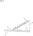
- ist eine Ansicht, mit der die Polarisationsrichtung des Laserlichts erläutert wird.
-
Fig. 1 zeigt eine schematische Ansicht einer bevorzugten Ausführungsform der vorliegenden Erfindung. Hierbei sind die dargestellten Elemente stark vereinfacht, um den Kern der vorliegenden Erfindung deutlicher darstellen zu können. - Insbesondere wird ein Werkstücks 1 dargestellt, das sich in einer Durchlaufrichtung durch die Beschichtungsvorrichtung bewegt (siehe Pfeil in
Fig. 1 ). Auf das Werkstück 1 wird mittels einer Andrückrolle 4 ein Beschichtungsmaterial 2 aufgedrückt, wobei das Beschichtungsmaterial 2 an der zum Werkstück 1 weisenden Seite mit einem Haftmittel versehen ist. - Ferner ist ein in der vorliegenden Ausführungsform ein Diodenlaser 5 vorgesehen, der einen Laserstrahl L emittiert, und über einen schematisch dargestellten Spiegel oder ein Prisma 6 in den Bereich der Wirkzone umlenkt. Alternativ sind auch Faserlaser oder CO2-Laser für diesen Einsatz geeignet. Dabei ist es bevorzugt vorgesehen, dass der Laserstrahl L in einem Winkel α von 20-30° bezogen auf die Ebene des Beschichtungsmaterials auf dieses auftrifft. Dieser bevorzugte Winkel ergibt sich aus den Brechzahlen von Luft (ca. 1) und dem für Kunststoff, wie dem Haftmittels, typischen Wert von 1,5.
- Erfindungsgemäß ist es vorgesehen, dass der Laser 5 derart ausgerichtet wird, dass in der Bezugsebene des Haftmittels 3 überwiegend P-Polarisation vorliegt. Die Bewertung, dass "überwiegend" Laserlicht mit P-Polarisation vorliegt, richtet sich danach, dass ein Diodenlaser eingesetzt wird, der eine bestimmte Polarisation aufweist. Diese dem Diodenlaser eigene Polarisation geht deshalb nichtverloren, weil zur Umlenkung des Laserlichts bis zum Haftmittel Spiegel und Prismen verwendet werden. Würde alternativ ein Glasfaserkabel verwendet, ginge die vom Diodenlaser emittierte Polarisation des Laserlichts durch Brechung/Streuung verloren. Allerdings kann es sein, dass trotz des genannten Vorgehens eine gewisse Brechung/Streuung oder Polarisationsverschiebung des Laserlichts nicht vermieden werden kann.
- Die Umsetzung der Laserleistung in Wärmeenergie hängt neben dem Einfallswinkel der Laserstrahlung auch von der optischen Eindringtiefe in das zu aktivierende Haftmittel ab. Um eine schnelle und zugleich gleichmäßig Aktivierung zu erreichen, hat es sich gezeigt, dass als optimale Eindringtiefe ca. 0,4 mm zu wählen ist.
- Da der Laserstrahl derart ausgerichtet ist, dass in der Bezugsebene im Wesentlichen P-Polarisation vorherrscht, und der Weg des Laserstrahls durch das Haftmittels durch die Wahl des Einfallwinkels maximiert wird, kann eine optimale Einkopplung der Energie des Laserstrahls in das Haftmittel zu dessen Aktivierung genutzt werden.
- In
Figur 2 ist schematisch ein Beschichtungsmaterial 2 gezeigt, auf dem ein zu aktivierendes Haftmittel 3 aufgebracht ist. Ferner ist ein Laserstrahls L abgebildet, der mit einem Lot auf der Ebene des Beschichtungsmaterials eine Bezugsebene E ausbildet. - In
Figur 3 wird in einer schematischen Seitenansicht die bevorzugte Polarisation des Laserlichts anschaulich erläutert: die Amplitude des Laserlichtstrahls L schwingt dabei in der zuvor definierten Bezugsebene, und trifft im Einfallswinkel α auf das Beschichtungsmaterial 2 auf. - Bei den im Rahmen dieser Erfindung durchgeführten Versuchen hat sich gezeigt, dass die maximal umgesetzte Leistung des Lasers bei der hier bevorzugten p-Polarisation des Laserlichts bei etwa 20-30° maximal ist. In diesem Winkelbereich findet zum einen eine geringe Streuung des Laserlichts am Haftmittel statt. Zum anderen wird eine gleichmäßig Durchwärmung des Haftmittel erreicht.
- Die Kennwerte für Laserlicht mit Mischpolarisation, welche üblicherweise eingesetzt wird, zeigt gegenüber dem Laserlicht mit p-Polarisation eine geringere umgesetzte Laserleistung. Dies gilt insbesondere für den Wickelbereich, in dem eine geringe Streuung des Laserlichts zu erwarten ist.
Claims (8)
- Verfahren zur Aktivierung eines auf einem Kantenband (2) oder auf einem Werkstück (1) befindlichen Haftmittels, unter Verwendung einer Vorrichtung, mit:einem Laser zur Ausgabe eines Laserstrahls zu einem Laserstrahlemitter, wobei der Laserstrahl derart auf das Kantenband (2) oder auf das Werkstück ausgerichtet ist, dass der Laserstrahl mit einem Lot auf der Fläche des Kantenbands (2) bzw. Werkstücks eine Bezugsebene (E) ausbildet, wobeidie Vorrichtung eine Bewegungseinrichtung zum Bewegen des Kantenbands (2) und eine Andruckrolle (4) aufweist, mit der nach der Aktivierung des Haftmittels das Kantenband an das Werkstück gedrückt wird, dadurch gekennzeichnet, dassder Laserstrahl mehr p-polarisiertes Licht als s-polarisiertes Licht in der Bezugsebene (E) aufweist undder Laserstrahl mit der Ebene des Kantenbands bzw. der Ebene des Werkstücks einen Winkel (α) von 20-30° ausbildet.
- Verfahren gemäß Anspruch 1, dadurch gekennzeichnet, dass mehr als 75% p-polarisiertes Licht in der Bezugsebene vorliegt.
- Verfahren gemäß Anspruch 1 oder 2, dadurch gekennzeichnet, dass weitestgehend ausschließlich p-polarisiertes Licht in der Bezugsebene vorliegt.
- Verfahren gemäß einem der vorangegangenen Ansprüche,
dadurch gekennzeichnet, dass zur Ablenkung des Laserstrahls ein Ablenkspiegel oder ein Prisma verwendet wird. - Verfahren gemäß einem der vorangegangenen Ansprüche,
dadurch gekennzeichnet, dass das Licht des Laserstrahls Direktstrahlung ist. - Verfahren gemäß Anspruch 1, bei der Laserstrahl derart auf das Kantenband oder auf das Werkstück ausgerichtet ist, dass der Laserstrahl mit der Ebene des Kantenbands bzw. der Ebene des Werkstücks einen Winkel (α) von 20-27° ausbildet.
- Verfahren gemäß einem der vorangegangenen Ansprüche,
dadurch gekennzeichnet, dass der Laser ein Laser ist, der einen Laserstrahl mit nur einer bestimmten Polarisation ausgibt, insbesondere Diodenlaser, Faserlaser, CO2-Laser oder Festkörperlaser. - Verfahren gemäß einem der vorangegangenen Ansprüche,
dadurch gekennzeichnet, dass ferner eine Bewegungseinrichtung für das Werkstück vorgesehen ist.
Applications Claiming Priority (2)
| Application Number | Priority Date | Filing Date | Title |
|---|---|---|---|
| DE102012202020A DE102012202020A1 (de) | 2012-02-10 | 2012-02-10 | Aktivierungsoptimierung |
| PCT/EP2013/052290 WO2013117571A1 (de) | 2012-02-10 | 2013-02-06 | Optimierung der aktivierung von haftmitteln durch laserstrahlung |
Publications (2)
| Publication Number | Publication Date |
|---|---|
| EP2812166A1 EP2812166A1 (de) | 2014-12-17 |
| EP2812166B1 true EP2812166B1 (de) | 2018-06-06 |
Family
ID=47722248
Family Applications (1)
| Application Number | Title | Priority Date | Filing Date |
|---|---|---|---|
| EP13704751.0A Not-in-force EP2812166B1 (de) | 2012-02-10 | 2013-02-06 | Optimierung der aktivierung von haftmtitteln durch laserstrahlung |
Country Status (6)
| Country | Link |
|---|---|
| US (2) | US20150041066A1 (de) |
| EP (1) | EP2812166B1 (de) |
| CN (1) | CN204221910U (de) |
| BR (1) | BR112014019569A8 (de) |
| DE (1) | DE102012202020A1 (de) |
| WO (1) | WO2013117571A1 (de) |
Families Citing this family (2)
| Publication number | Priority date | Publication date | Assignee | Title |
|---|---|---|---|---|
| DE102013226213A1 (de) * | 2013-12-17 | 2015-06-18 | Homag Holzbearbeitungssysteme Gmbh | Mehrschicht-Beschichtungsmaterial sowie Beschichtungsverfahren |
| WO2016167079A1 (ja) * | 2015-04-13 | 2016-10-20 | 株式会社大成商事 | 木質積層体の製造方法 |
Citations (1)
| Publication number | Priority date | Publication date | Assignee | Title |
|---|---|---|---|---|
| EP2239086A1 (de) * | 2009-04-09 | 2010-10-13 | ALANOD Aluminium-Veredlung GmbH & Co. KG | Verfahren zum Laserverschweißen eines Verbundmaterials mit einem Bauteil sowie laserschweißbares Verbundmaterial für ein solches Verfahren |
Family Cites Families (8)
| Publication number | Priority date | Publication date | Assignee | Title |
|---|---|---|---|---|
| US3560291A (en) * | 1964-03-27 | 1971-02-02 | Mobil Oil Corp | Bonding thermoplastic resin films by means of radiation from a laser source |
| US3790744A (en) * | 1971-07-19 | 1974-02-05 | American Can Co | Method of forming a line of weakness in a multilayer laminate |
| DE3827297A1 (de) * | 1988-08-11 | 1990-02-15 | Fraunhofer Ges Forschung | Vorrichtung und verfahren zum fuegen von werkstuecken mit laserstrahlung |
| DE19502140C1 (de) * | 1995-01-25 | 1996-05-15 | Thyssen Stahl Ag | Verfahren zum laserunterstützten Plattieren von Band und dessen Anwendung |
| US6451152B1 (en) * | 2000-05-24 | 2002-09-17 | The Boeing Company | Method for heating and controlling temperature of composite material during automated placement |
| EP2347873B1 (de) | 2005-11-23 | 2022-03-23 | HOMAG GmbH | Verfahren und Vorrichtung zur Beschichtung von Bauteilen |
| DE102006021171A1 (de) * | 2006-05-06 | 2007-11-08 | W. Döllken & Co. GmbH | Deckleiste |
| US20090114630A1 (en) * | 2007-11-05 | 2009-05-07 | Hawryluk Andrew M | Minimization of surface reflectivity variations |
-
2012
- 2012-02-10 DE DE102012202020A patent/DE102012202020A1/de not_active Withdrawn
-
2013
- 2013-02-06 WO PCT/EP2013/052290 patent/WO2013117571A1/de not_active Ceased
- 2013-02-06 EP EP13704751.0A patent/EP2812166B1/de not_active Not-in-force
- 2013-02-06 US US14/377,911 patent/US20150041066A1/en not_active Abandoned
- 2013-02-06 BR BR112014019569A patent/BR112014019569A8/pt not_active Application Discontinuation
- 2013-02-06 CN CN201390000255.7U patent/CN204221910U/zh not_active Expired - Lifetime
-
2017
- 2017-04-18 US US15/489,934 patent/US10442031B2/en not_active Expired - Fee Related
Patent Citations (1)
| Publication number | Priority date | Publication date | Assignee | Title |
|---|---|---|---|---|
| EP2239086A1 (de) * | 2009-04-09 | 2010-10-13 | ALANOD Aluminium-Veredlung GmbH & Co. KG | Verfahren zum Laserverschweißen eines Verbundmaterials mit einem Bauteil sowie laserschweißbares Verbundmaterial für ein solches Verfahren |
Also Published As
| Publication number | Publication date |
|---|---|
| WO2013117571A1 (de) | 2013-08-15 |
| US20150041066A1 (en) | 2015-02-12 |
| US20170216963A1 (en) | 2017-08-03 |
| EP2812166A1 (de) | 2014-12-17 |
| BR112014019569A2 (de) | 2017-06-20 |
| BR112014019569A8 (pt) | 2017-07-11 |
| DE102012202020A1 (de) | 2013-08-14 |
| CN204221910U (zh) | 2015-03-25 |
| US10442031B2 (en) | 2019-10-15 |
Similar Documents
| Publication | Publication Date | Title |
|---|---|---|
| EP2118027B1 (de) | Verfahren und vorrichtung zum herstellen eines trennspalts in einer glasscheibe | |
| AT13206U1 (de) | Verfahren und Anordnung zum Teilen von Flachglas | |
| EP2113332A1 (de) | Verfahren und Laservorrichtung zum Bearbeiten und/oder Verbinden von Werkstücken mittels Laserstrahlung mit Leistungswirk- und Pilotlaser und mindestens einem diffraktiven optischen Element | |
| DE1479686A1 (de) | Verfahren zum Binden eines thermoplastischen Koerpers an einen anderen Koerper | |
| EP1175955B1 (de) | Verfahren und Vorrichtung zu Schweissnahtglättung beim Strahlschweissen | |
| EP3814139A1 (de) | Vorrichtung und verfahren zum trennen einer verbundsicherheitsglastafel | |
| DE102011075328A1 (de) | Vorrichtung und Verfahren zum Randentschichten und Kerben beschichteter Substrate | |
| DE102012202020A1 (de) | Aktivierungsoptimierung | |
| DE102009050858A1 (de) | Vorrichtung und Verfahren zur Bekantung von Werkstücken | |
| EP4031315A1 (de) | Laserschneidverfahren und zugehörige laserschneidvorrichtung | |
| EP0771606B1 (de) | Strahlschweissverfahren mit Kantenverrundung | |
| DE102019103211A1 (de) | Verfahren und System zur Bearbeitung eines Werkstücks mit einem Bearbeitungsstahl sowie Vorrichtung zur Bestimmung der Lage eines zu bearbeitenden Werkstücks relativ zu einem Bearbeitungsstahl und Verwendung einer solchen | |
| DE102010010147A1 (de) | Strahlschweißverfahren und zugehörige Schweißvorrichtung | |
| DE102007017363A1 (de) | Vorrichtung und Verfahren zur Bearbeitung von Bauteilen | |
| DE102013222636A1 (de) | Verfahren zum Aufbringen einer Beschichtung auf Werkstücke und Vorrichtung zum Beschichten von Werkstücken | |
| DE102010032781A1 (de) | Verfahren zur trennenden Bearbeitung von Werkstücken mit Laserstrahlen | |
| EP2442953A1 (de) | Vorrichtung und verfahren zur bekantung von werkstücken | |
| DE10332845B3 (de) | Vorrichtung und Verfahren zum Abisolieren eines Flachbandkabels | |
| DE102007017364B4 (de) | Vorrichtung und ein Verfahren zur Bearbeitung von Bauteilen oder Werkstücken mit polarisierter Strahlung | |
| DE19718287C1 (de) | Verfahren zur Modifizierung von Holzoberflächen | |
| EP2445688A1 (de) | Bearbeitungszentrum | |
| EP2511059B1 (de) | Vorrichtung und Verfahren zur Bekantung von Werkstücken | |
| DE102007020704B4 (de) | Einrichtung für die Bearbeitung eines Werkstückes mit einem Laserstrahl | |
| DE102013226213A1 (de) | Mehrschicht-Beschichtungsmaterial sowie Beschichtungsverfahren | |
| DE102005010269A1 (de) | Verfahren zum Herstellen eines Bauteils aus zumindest zwei Bauelementen |
Legal Events
| Date | Code | Title | Description |
|---|---|---|---|
| PUAI | Public reference made under article 153(3) epc to a published international application that has entered the european phase |
Free format text: ORIGINAL CODE: 0009012 |
|
| 17P | Request for examination filed |
Effective date: 20140805 |
|
| AK | Designated contracting states |
Kind code of ref document: A1 Designated state(s): AL AT BE BG CH CY CZ DE DK EE ES FI FR GB GR HR HU IE IS IT LI LT LU LV MC MK MT NL NO PL PT RO RS SE SI SK SM TR |
|
| AX | Request for extension of the european patent |
Extension state: BA ME |
|
| DAX | Request for extension of the european patent (deleted) | ||
| RAP1 | Party data changed (applicant data changed or rights of an application transferred) |
Owner name: HOMAG GMBH |
|
| 17Q | First examination report despatched |
Effective date: 20161014 |
|
| STAA | Information on the status of an ep patent application or granted ep patent |
Free format text: STATUS: EXAMINATION IS IN PROGRESS |
|
| GRAP | Despatch of communication of intention to grant a patent |
Free format text: ORIGINAL CODE: EPIDOSNIGR1 |
|
| STAA | Information on the status of an ep patent application or granted ep patent |
Free format text: STATUS: GRANT OF PATENT IS INTENDED |
|
| INTG | Intention to grant announced |
Effective date: 20180222 |
|
| GRAS | Grant fee paid |
Free format text: ORIGINAL CODE: EPIDOSNIGR3 |
|
| GRAA | (expected) grant |
Free format text: ORIGINAL CODE: 0009210 |
|
| STAA | Information on the status of an ep patent application or granted ep patent |
Free format text: STATUS: THE PATENT HAS BEEN GRANTED |
|
| RIN1 | Information on inventor provided before grant (corrected) |
Inventor name: PETRAK, AXEL |
|
| AK | Designated contracting states |
Kind code of ref document: B1 Designated state(s): AL AT BE BG CH CY CZ DE DK EE ES FI FR GB GR HR HU IE IS IT LI LT LU LV MC MK MT NL NO PL PT RO RS SE SI SK SM TR |
|
| REG | Reference to a national code |
Ref country code: GB Ref legal event code: FG4D Free format text: NOT ENGLISH |
|
| REG | Reference to a national code |
Ref country code: CH Ref legal event code: EP Ref country code: AT Ref legal event code: REF Ref document number: 1005556 Country of ref document: AT Kind code of ref document: T Effective date: 20180615 |
|
| REG | Reference to a national code |
Ref country code: IE Ref legal event code: FG4D Free format text: LANGUAGE OF EP DOCUMENT: GERMAN |
|
| REG | Reference to a national code |
Ref country code: DE Ref legal event code: R096 Ref document number: 502013010322 Country of ref document: DE |
|
| REG | Reference to a national code |
Ref country code: NL Ref legal event code: MP Effective date: 20180606 |
|
| REG | Reference to a national code |
Ref country code: LT Ref legal event code: MG4D |
|
| PG25 | Lapsed in a contracting state [announced via postgrant information from national office to epo] |
Ref country code: BG Free format text: LAPSE BECAUSE OF FAILURE TO SUBMIT A TRANSLATION OF THE DESCRIPTION OR TO PAY THE FEE WITHIN THE PRESCRIBED TIME-LIMIT Effective date: 20180906 Ref country code: FI Free format text: LAPSE BECAUSE OF FAILURE TO SUBMIT A TRANSLATION OF THE DESCRIPTION OR TO PAY THE FEE WITHIN THE PRESCRIBED TIME-LIMIT Effective date: 20180606 Ref country code: NO Free format text: LAPSE BECAUSE OF FAILURE TO SUBMIT A TRANSLATION OF THE DESCRIPTION OR TO PAY THE FEE WITHIN THE PRESCRIBED TIME-LIMIT Effective date: 20180906 Ref country code: CY Free format text: LAPSE BECAUSE OF FAILURE TO SUBMIT A TRANSLATION OF THE DESCRIPTION OR TO PAY THE FEE WITHIN THE PRESCRIBED TIME-LIMIT Effective date: 20180606 Ref country code: LT Free format text: LAPSE BECAUSE OF FAILURE TO SUBMIT A TRANSLATION OF THE DESCRIPTION OR TO PAY THE FEE WITHIN THE PRESCRIBED TIME-LIMIT Effective date: 20180606 Ref country code: ES Free format text: LAPSE BECAUSE OF FAILURE TO SUBMIT A TRANSLATION OF THE DESCRIPTION OR TO PAY THE FEE WITHIN THE PRESCRIBED TIME-LIMIT Effective date: 20180606 Ref country code: SE Free format text: LAPSE BECAUSE OF FAILURE TO SUBMIT A TRANSLATION OF THE DESCRIPTION OR TO PAY THE FEE WITHIN THE PRESCRIBED TIME-LIMIT Effective date: 20180606 |
|
| PG25 | Lapsed in a contracting state [announced via postgrant information from national office to epo] |
Ref country code: LV Free format text: LAPSE BECAUSE OF FAILURE TO SUBMIT A TRANSLATION OF THE DESCRIPTION OR TO PAY THE FEE WITHIN THE PRESCRIBED TIME-LIMIT Effective date: 20180606 Ref country code: RS Free format text: LAPSE BECAUSE OF FAILURE TO SUBMIT A TRANSLATION OF THE DESCRIPTION OR TO PAY THE FEE WITHIN THE PRESCRIBED TIME-LIMIT Effective date: 20180606 Ref country code: GR Free format text: LAPSE BECAUSE OF FAILURE TO SUBMIT A TRANSLATION OF THE DESCRIPTION OR TO PAY THE FEE WITHIN THE PRESCRIBED TIME-LIMIT Effective date: 20180907 Ref country code: HR Free format text: LAPSE BECAUSE OF FAILURE TO SUBMIT A TRANSLATION OF THE DESCRIPTION OR TO PAY THE FEE WITHIN THE PRESCRIBED TIME-LIMIT Effective date: 20180606 |
|
| PG25 | Lapsed in a contracting state [announced via postgrant information from national office to epo] |
Ref country code: NL Free format text: LAPSE BECAUSE OF FAILURE TO SUBMIT A TRANSLATION OF THE DESCRIPTION OR TO PAY THE FEE WITHIN THE PRESCRIBED TIME-LIMIT Effective date: 20180606 |
|
| PG25 | Lapsed in a contracting state [announced via postgrant information from national office to epo] |
Ref country code: EE Free format text: LAPSE BECAUSE OF FAILURE TO SUBMIT A TRANSLATION OF THE DESCRIPTION OR TO PAY THE FEE WITHIN THE PRESCRIBED TIME-LIMIT Effective date: 20180606 Ref country code: PL Free format text: LAPSE BECAUSE OF FAILURE TO SUBMIT A TRANSLATION OF THE DESCRIPTION OR TO PAY THE FEE WITHIN THE PRESCRIBED TIME-LIMIT Effective date: 20180606 Ref country code: IS Free format text: LAPSE BECAUSE OF FAILURE TO SUBMIT A TRANSLATION OF THE DESCRIPTION OR TO PAY THE FEE WITHIN THE PRESCRIBED TIME-LIMIT Effective date: 20181006 Ref country code: SK Free format text: LAPSE BECAUSE OF FAILURE TO SUBMIT A TRANSLATION OF THE DESCRIPTION OR TO PAY THE FEE WITHIN THE PRESCRIBED TIME-LIMIT Effective date: 20180606 Ref country code: CZ Free format text: LAPSE BECAUSE OF FAILURE TO SUBMIT A TRANSLATION OF THE DESCRIPTION OR TO PAY THE FEE WITHIN THE PRESCRIBED TIME-LIMIT Effective date: 20180606 Ref country code: RO Free format text: LAPSE BECAUSE OF FAILURE TO SUBMIT A TRANSLATION OF THE DESCRIPTION OR TO PAY THE FEE WITHIN THE PRESCRIBED TIME-LIMIT Effective date: 20180606 |
|
| PG25 | Lapsed in a contracting state [announced via postgrant information from national office to epo] |
Ref country code: SM Free format text: LAPSE BECAUSE OF FAILURE TO SUBMIT A TRANSLATION OF THE DESCRIPTION OR TO PAY THE FEE WITHIN THE PRESCRIBED TIME-LIMIT Effective date: 20180606 |
|
| REG | Reference to a national code |
Ref country code: DE Ref legal event code: R097 Ref document number: 502013010322 Country of ref document: DE |
|
| PLBE | No opposition filed within time limit |
Free format text: ORIGINAL CODE: 0009261 |
|
| STAA | Information on the status of an ep patent application or granted ep patent |
Free format text: STATUS: NO OPPOSITION FILED WITHIN TIME LIMIT |
|
| 26N | No opposition filed |
Effective date: 20190307 |
|
| PG25 | Lapsed in a contracting state [announced via postgrant information from national office to epo] |
Ref country code: DK Free format text: LAPSE BECAUSE OF FAILURE TO SUBMIT A TRANSLATION OF THE DESCRIPTION OR TO PAY THE FEE WITHIN THE PRESCRIBED TIME-LIMIT Effective date: 20180606 Ref country code: SI Free format text: LAPSE BECAUSE OF FAILURE TO SUBMIT A TRANSLATION OF THE DESCRIPTION OR TO PAY THE FEE WITHIN THE PRESCRIBED TIME-LIMIT Effective date: 20180606 |
|
| REG | Reference to a national code |
Ref country code: CH Ref legal event code: PL |
|
| GBPC | Gb: european patent ceased through non-payment of renewal fee |
Effective date: 20190206 |
|
| PG25 | Lapsed in a contracting state [announced via postgrant information from national office to epo] |
Ref country code: LU Free format text: LAPSE BECAUSE OF NON-PAYMENT OF DUE FEES Effective date: 20190206 Ref country code: MC Free format text: LAPSE BECAUSE OF FAILURE TO SUBMIT A TRANSLATION OF THE DESCRIPTION OR TO PAY THE FEE WITHIN THE PRESCRIBED TIME-LIMIT Effective date: 20180606 |
|
| REG | Reference to a national code |
Ref country code: BE Ref legal event code: MM Effective date: 20190228 |
|
| REG | Reference to a national code |
Ref country code: IE Ref legal event code: MM4A |
|
| PG25 | Lapsed in a contracting state [announced via postgrant information from national office to epo] |
Ref country code: AL Free format text: LAPSE BECAUSE OF FAILURE TO SUBMIT A TRANSLATION OF THE DESCRIPTION OR TO PAY THE FEE WITHIN THE PRESCRIBED TIME-LIMIT Effective date: 20180606 |
|
| PG25 | Lapsed in a contracting state [announced via postgrant information from national office to epo] |
Ref country code: CH Free format text: LAPSE BECAUSE OF NON-PAYMENT OF DUE FEES Effective date: 20190228 Ref country code: LI Free format text: LAPSE BECAUSE OF NON-PAYMENT OF DUE FEES Effective date: 20190228 |
|
| PG25 | Lapsed in a contracting state [announced via postgrant information from national office to epo] |
Ref country code: GB Free format text: LAPSE BECAUSE OF NON-PAYMENT OF DUE FEES Effective date: 20190206 Ref country code: IE Free format text: LAPSE BECAUSE OF NON-PAYMENT OF DUE FEES Effective date: 20190206 |
|
| PG25 | Lapsed in a contracting state [announced via postgrant information from national office to epo] |
Ref country code: BE Free format text: LAPSE BECAUSE OF NON-PAYMENT OF DUE FEES Effective date: 20190228 Ref country code: FR Free format text: LAPSE BECAUSE OF NON-PAYMENT OF DUE FEES Effective date: 20190228 |
|
| PG25 | Lapsed in a contracting state [announced via postgrant information from national office to epo] |
Ref country code: TR Free format text: LAPSE BECAUSE OF FAILURE TO SUBMIT A TRANSLATION OF THE DESCRIPTION OR TO PAY THE FEE WITHIN THE PRESCRIBED TIME-LIMIT Effective date: 20180606 |
|
| PG25 | Lapsed in a contracting state [announced via postgrant information from national office to epo] |
Ref country code: PT Free format text: LAPSE BECAUSE OF FAILURE TO SUBMIT A TRANSLATION OF THE DESCRIPTION OR TO PAY THE FEE WITHIN THE PRESCRIBED TIME-LIMIT Effective date: 20181008 Ref country code: MT Free format text: LAPSE BECAUSE OF FAILURE TO SUBMIT A TRANSLATION OF THE DESCRIPTION OR TO PAY THE FEE WITHIN THE PRESCRIBED TIME-LIMIT Effective date: 20180606 |
|
| PG25 | Lapsed in a contracting state [announced via postgrant information from national office to epo] |
Ref country code: HU Free format text: LAPSE BECAUSE OF FAILURE TO SUBMIT A TRANSLATION OF THE DESCRIPTION OR TO PAY THE FEE WITHIN THE PRESCRIBED TIME-LIMIT; INVALID AB INITIO Effective date: 20130206 |
|
| PG25 | Lapsed in a contracting state [announced via postgrant information from national office to epo] |
Ref country code: MK Free format text: LAPSE BECAUSE OF FAILURE TO SUBMIT A TRANSLATION OF THE DESCRIPTION OR TO PAY THE FEE WITHIN THE PRESCRIBED TIME-LIMIT Effective date: 20180606 |
|
| P01 | Opt-out of the competence of the unified patent court (upc) registered |
Effective date: 20230529 |
|
| PGFP | Annual fee paid to national office [announced via postgrant information from national office to epo] |
Ref country code: AT Payment date: 20240228 Year of fee payment: 12 |
|
| PGFP | Annual fee paid to national office [announced via postgrant information from national office to epo] |
Ref country code: DE Payment date: 20240216 Year of fee payment: 12 |
|
| PGFP | Annual fee paid to national office [announced via postgrant information from national office to epo] |
Ref country code: IT Payment date: 20240223 Year of fee payment: 12 |
|
| REG | Reference to a national code |
Ref country code: DE Ref legal event code: R119 Ref document number: 502013010322 Country of ref document: DE |
|
| REG | Reference to a national code |
Ref country code: AT Ref legal event code: MM01 Ref document number: 1005556 Country of ref document: AT Kind code of ref document: T Effective date: 20250206 |
|
| PG25 | Lapsed in a contracting state [announced via postgrant information from national office to epo] |
Ref country code: AT Free format text: LAPSE BECAUSE OF NON-PAYMENT OF DUE FEES Effective date: 20250206 |
|
| PG25 | Lapsed in a contracting state [announced via postgrant information from national office to epo] |
Ref country code: DE Free format text: LAPSE BECAUSE OF NON-PAYMENT OF DUE FEES Effective date: 20250902 |
|
| PG25 | Lapsed in a contracting state [announced via postgrant information from national office to epo] |
Ref country code: IT Free format text: LAPSE BECAUSE OF NON-PAYMENT OF DUE FEES Effective date: 20250206 |