EP2811739B1 - Terminal, image communication control server, and system and method for image communication using same - Google Patents
Terminal, image communication control server, and system and method for image communication using same Download PDFInfo
- Publication number
- EP2811739B1 EP2811739B1 EP13743668.9A EP13743668A EP2811739B1 EP 2811739 B1 EP2811739 B1 EP 2811739B1 EP 13743668 A EP13743668 A EP 13743668A EP 2811739 B1 EP2811739 B1 EP 2811739B1
- Authority
- EP
- European Patent Office
- Prior art keywords
- terminal
- orientation
- video call
- image
- control server
- Prior art date
- Legal status (The legal status is an assumption and is not a legal conclusion. Google has not performed a legal analysis and makes no representation as to the accuracy of the status listed.)
- Active
Links
- 238000000034 method Methods 0.000 title claims description 30
- 238000004891 communication Methods 0.000 title description 22
- 230000005540 biological transmission Effects 0.000 claims description 2
- 238000010586 diagram Methods 0.000 description 20
- 230000001413 cellular effect Effects 0.000 description 3
- 238000005516 engineering process Methods 0.000 description 3
- 230000006870 function Effects 0.000 description 3
- 230000001419 dependent effect Effects 0.000 description 2
- 230000005484 gravity Effects 0.000 description 2
- 230000000977 initiatory effect Effects 0.000 description 2
- 238000012986 modification Methods 0.000 description 2
- 230000004048 modification Effects 0.000 description 2
- 238000013500 data storage Methods 0.000 description 1
- 238000011161 development Methods 0.000 description 1
- 230000018109 developmental process Effects 0.000 description 1
- 230000000694 effects Effects 0.000 description 1
- 210000000887 face Anatomy 0.000 description 1
- 230000001815 facial effect Effects 0.000 description 1
- 210000003128 head Anatomy 0.000 description 1
- 238000013507 mapping Methods 0.000 description 1
- 230000003287 optical effect Effects 0.000 description 1
- 238000012545 processing Methods 0.000 description 1
- 230000004044 response Effects 0.000 description 1
Images


Classifications
-
- H—ELECTRICITY
- H04—ELECTRIC COMMUNICATION TECHNIQUE
- H04N—PICTORIAL COMMUNICATION, e.g. TELEVISION
- H04N7/00—Television systems
- H04N7/14—Systems for two-way working
- H04N7/141—Systems for two-way working between two video terminals, e.g. videophone
- H04N7/142—Constructional details of the terminal equipment, e.g. arrangements of the camera and the display
-
- H—ELECTRICITY
- H04—ELECTRIC COMMUNICATION TECHNIQUE
- H04N—PICTORIAL COMMUNICATION, e.g. TELEVISION
- H04N1/00—Scanning, transmission or reproduction of documents or the like, e.g. facsimile transmission; Details thereof
- H04N1/00127—Connection or combination of a still picture apparatus with another apparatus, e.g. for storage, processing or transmission of still picture signals or of information associated with a still picture
- H04N1/00204—Connection or combination of a still picture apparatus with another apparatus, e.g. for storage, processing or transmission of still picture signals or of information associated with a still picture with a digital computer or a digital computer system, e.g. an internet server
- H04N1/00244—Connection or combination of a still picture apparatus with another apparatus, e.g. for storage, processing or transmission of still picture signals or of information associated with a still picture with a digital computer or a digital computer system, e.g. an internet server with a server, e.g. an internet server
-
- G—PHYSICS
- G06—COMPUTING; CALCULATING OR COUNTING
- G06T—IMAGE DATA PROCESSING OR GENERATION, IN GENERAL
- G06T3/00—Geometric image transformation in the plane of the image
- G06T3/60—Rotation of a whole image or part thereof
-
- H—ELECTRICITY
- H04—ELECTRIC COMMUNICATION TECHNIQUE
- H04N—PICTORIAL COMMUNICATION, e.g. TELEVISION
- H04N7/00—Television systems
- H04N7/14—Systems for two-way working
- H04N7/15—Conference systems
- H04N7/152—Multipoint control units therefor
-
- H—ELECTRICITY
- H04—ELECTRIC COMMUNICATION TECHNIQUE
- H04N—PICTORIAL COMMUNICATION, e.g. TELEVISION
- H04N2201/00—Indexing scheme relating to scanning, transmission or reproduction of documents or the like, and to details thereof
- H04N2201/32—Circuits or arrangements for control or supervision between transmitter and receiver or between image input and image output device, e.g. between a still-image camera and its memory or between a still-image camera and a printer device
- H04N2201/3201—Display, printing, storage or transmission of additional information, e.g. ID code, date and time or title
- H04N2201/3225—Display, printing, storage or transmission of additional information, e.g. ID code, date and time or title of data relating to an image, a page or a document
- H04N2201/3252—Image capture parameters, e.g. resolution, illumination conditions, orientation of the image capture device
Definitions
- the present disclosure relates to video call technology, and, more particularly, to a system and method, for a video call, that display respective users in the same direction as a reference orientation or a reference posture in a video screen.
- the invention relates to a system for video call, a method of operating a video call control server, and a method of operating a terminal used in a video call system.
- a video call service can provide a one-to-one video call between a caller and a called party and a group video call.
- group video calls are mainly made through a control device called a multipoint control unit (MCU).
- MCU multipoint control unit
- the MCU is a device that receives voice and images transmitted by respective portable terminals, combines the plurality of voices and images into one, and then transmits the combined voice and image data to the respective portable terminals.
- FIG. 1 is a diagram showing an existing video call system employing an MCU.
- an MCU 20 combines images a, b, c, and d transmitted by respective portable terminals 11, 12, 13, and 14 as they are, and then delivers a combined image I, to the respective portable terminals 11 to 14.
- the images a to d in the combined image I may have different display orientations according to the various orientations being used by users of the respective terminals 11 to 14during the video call.
- the portable terminal 11 and the portable terminal 14 are rotated by 90 degrees clockwise with respect to a reference orientation, and capture images, and the portable terminal 12 and the portable terminal 13 capture images in the reference orientation
- the images a and d captured by the portable terminal 11 and the portable terminal 14 each are combined by the MCU 20 in their then-active orientation, i.e., rotated by 90 degrees counterclockwise.
- the images b and c, however, captured by the portable terminal 12 and the portable terminal 13 are each combined by the MCU 20 in their then-active orientation, namely, the reference orientation.
- the images a and d in the combined image I are shown in the orientation rotated by 90 degrees counterclockwise, and thus the viewers see a combined image that looks strange and is hard on the eyes.
- US 2011/0249073 A1 refers to a technique for establishing a video conference during a phone call.
- a method for initiating a video conference using a first mobile device. The method presents, during an audio call through a wireless communication network with a second device, a selectable user-interface, UI, item on the first mobile device for switching from the audio call to the video conference. The method receives a selection of the selectable UI item. The method initiates the video conference without terminating the audio call. The method terminates the audio call before allowing the first and second devices to present audio and video data exchanged through the video conference.
- US 2009/0309897 A1 refers to a communication terminal and communication system and display method of communication terminal.
- the communication terminal and the communication system are able to adaptively update sizes and positions of screens in accordance with the situation without operation by a user, and a display method of the communication terminal, which performs processing of individual packets in a linked manner under the control of a display image control portion 306 based on an address of a transmitting side.
- a sound pressure (volume) of audio information (VoIP) from the same transmitting side address
- the terminal etc. calculate the screen sizes for mapping of packets of the video information from the same transmitting side address and corrects the top/bottom of the same screen or displays an instructed animated character based on top/bottom information, instruction information, etc. described in the packets of the control information from the same transmitting side address.
- EP 1 298 925 A2 refers to a moving picture communication method and apparatus.
- picture information of a user's party enlarged and pivoted at an angle of some 90 degrees
- an image display of a cell-phone type moving picture communication apparatus of a user which has been pivoted at an angle of nearly 90 degrees in an either rightward or leftward direction of the user's cell-phone type moving picture communication apparatus when the user faces the image display of the user's communication apparatus, then a pivoting unit pivots user's self-picture information in response to pivotal movement of the user's cell-phone type moving picture communication apparatus.
- the image display has an aspect ratio defined by different vertical and horizontal lengths.
- An image pick-up unit of the pivoted user's cell-phone type moving picture communication apparatus produces the user's self-picture information.
- An encoding unit encodes the pivoted user's self-picture information.
- a transmitting unit transmits the encoded user's self-picture information to a cell-phone type moving picture communication apparatus of the user's party. Since the party's cell-phone type moving picture communication apparatus receives the pivoted user's self-picture information from the user's cell-phone type moving picture communication apparatus, the user's self-picture information properly oriented with respect to the vertical axis of the earth is displayed on the party's cell-phone type moving picture communication apparatus.
- a system for video call according to claim 1.
- a method of operating a video call control server according to claim 3.
- a method of operating a terminal used in a video call system according to claim 5.
- a system for a video call includes one or more terminals that transmit images obtained by capturing or photographing video call users, and a video call control server that generates a combined image by combining the images transmitted by the one or more terminals and transmitting the combined image to the terminals.
- the respective images are rotated according to information on orientations sensed by the terminals, and combined into the combined image.
- the terminal may be configured to transmit the orientation information to the video call control server.
- the video call control server may rotate the images received from the terminals to a reference orientation according to the orientation information, and generate the combined image by combining the rotated images.
- the terminals may transmit aspect ratio information on the terminals to the video call control server together with the orientation information. Also, when the orientations of the terminals are changed after the orientation information is transmitted, the terminals may transmit updated orientation information corresponding to the changed orientations to the video call control server.
- the terminals may sense their orientations, rotate captured images to a reference orientation according to information on the sensed orientations, and transmit the rotated images to the video call control server. Also, when the orientations of the terminals are changed after the orientation information is transmitted, the terminals may rotate captured images according to orientation information corresponding to the changed orientations, and transmit the rotated images to the video call control server.
- the video call control server may check screen modes of the terminals using the images transmitted by the terminals, generate the combined image according to the screen modes, and transmit the combined image to the terminals. Also, the video call control server may check aspect ratios together with the screen modes of the terminals using the images received from the terminals, generate the combined image according to the screen modes and the aspect ratios, and transmit the combined image to the terminals.
- a method for a video call includes transmitting, at one or more terminals, images obtained by capturing video call users, generating, at a video call control server, a combined image by combining the images transmitted by the one or more terminals, and transmitting, at the video call control server, the combined image to the terminals.
- the respective images constituting the combined image are rotated according to information on orientations sensed by the terminals, and combined.
- transmitting the images may further include transmitting the orientation information on the terminals to the video call control server.
- generating the combined image may include rotating the images received from the terminals to a reference orientation according to the received orientation information, and generating the combined image by combining the rotated images.
- transmitting the images may further include transmitting aspect ratio information on the terminals to the video call control server together with the orientation information.
- the terminals may transmit orientation information corresponding to the changed orientations to the video call control server.
- transmitting the images may further include sensing orientations of the terminals, and rotating the captured images to a reference orientation according to information on the sensed orientations and transmitting the rotated images to the video call control server.
- the terminals may rotate the captured images according to orientation information corresponding to the changed orientations and transmit the rotated images to the video call control server.
- Generating the combined image may further include checking screen modes of the terminals using the images transmitted by the terminals, and generating the combined image according to the screen modes. Also, generating the combined image may further include checking aspect ratios of the terminals together with the screen modes using the images received from the terminals, and generating the combined image according to the screen modes and the aspect ratios.
- FIG. 2 is a diagram of a system for a video call according to a first exemplary embodiment.
- a system 200 for a video call includes a plurality of terminals 202 and a video call control server 204. Although four terminals 202 are shown in the drawing, the number of terminals 202 is not limited to four, and two or more terminals 202 may be used.
- Each of the terminals 202 requests a video call from the video call control server 204.
- the terminals 202 may include all types of terminals such as a portable terminal, a fixed terminal, a wireless terminal, a wired terminal, etc. capable of participating in a video call.
- a cellular phone such as a smartphone, a personal digital assistant (PDA), a tablet personal computer (PC), a laptop computer, or a desktop computer may be a terminal in the present disclosure.
- a portable terminal in the form of a cellular phone is shown here, but the terminals 202 are not limited to portable terminals in the form of a cellular phone.
- Each of the terminals 202 transmits orientation information about the terminal 202 itself to the video call control server 204 while requesting the video call from the video call control server 204.
- the orientation information is any type of information that can be used to determine how much the corresponding terminal 202 has been rotated with respect to a reference orientation.
- FIG. 3 is a diagram showing orientations of a terminal according to the first exemplary embodiment rotated with respect to a reference orientation.
- each terminal 202 may be in a state as shown in FIG. 3 (reference) in which the terminal 202 is in a reference orientation.
- each terminal 202 may be in a state as shown in FIG. 3 (a) in which the terminal 202 is rotated by 90 degrees clockwise with respect to a reference orientation (i.e., rotated by 270 degrees counterclockwise with respect to the reference orientation).
- each terminal 202 may be in a state as shown in FIG.
- each terminal 202 may be in a state as shown in FIG. 3 (c) in which the terminal 202 is rotated by 270 degrees clockwise with respect to the reference orientation (rotated by 90 degrees counterclockwise with respect to the reference orientation).
- the rotation state of the terminal 202 is understood to vary from the reference orientation in multiples of 90 degrees (i.e., 0 degree, 90 degrees, 180 degrees, and 270 degrees), and this rotation state depends upon how much a user rotates the terminal 202. Since it is practically impossible for a human user carrying the terminal 202 in one hand to consistently rotate the terminal 202 at an accurate angle, a threshold value for a rotation angle of the terminal 202 may be set in advance, and the rotation state may be changed according to the threshold value.
- the rotation state may be set to the reference state when the rotation angle of the terminal 202 is -45 degrees to 45 degrees; rotated by 90 degrees clockwise when the rotation angle is 46 degrees to 135 degrees; rotated by 180 degrees clockwise when the rotation angle is 136 degrees to 225 degrees; and rotated by 270 degrees clockwise when the rotation angle is 226 degrees to 315 degrees.
- the reference orientation of the terminal 202 may vary according to a setting, a communication service provider, etc., of the terminal 202. For example, a state in which the screen of the terminal 202 is horizontally or vertically placed may be determined as the reference orientation.
- each terminal 202 transmits its own orientation information, dependent on a state in which the terminal 202 is rotated with respect to the reference orientation, to the video call control server 204. Meanwhile, when its own orientation is changed at a time after a terminal 202 has already transmitted its own orientation information to the video call control server 204, the terminal 202 again transmits orientation information indicating the changed orientation to the video call control server 204.
- each terminal 202 may transmit its own reference aspect ratio information to the video call control server 204.
- the reference aspect ratio information denotes a width-to-height ratio of the corresponding terminal 202 in the reference orientation.
- width-to-height aspect ratios of the terminals 202 may be 4:3 or 16:9 in the reference orientation, and each terminal 202 may transmit such reference aspect ratio information to the video call control server 204.
- each terminal 202 may transmit its own orientation information and reference aspect ratio information using a session initiation protocol (SIP) message.
- SIP session initiation protocol
- Each terminal 202 transmits an image obtained by capturing a user to the video call control server 204.
- the image may be shown to be rotated by a predetermined angle with respect to a reference orientation according to a orientation of the terminal 202 when capturing the image. For example, when the terminal 202 is rotated by 90 degrees clockwise with respect to the reference orientation to capture the user, an image obtained by capturing the user is shown to be rotated by 90 degrees counterclockwise with respect to the reference orientation.
- the video call control server 204 rotates the image again to the reference orientation, and then generates a combined image by combining respective images.
- the video call control server 204 may check whether or not an image transmitted from each terminal 202 has been rotated by the predetermined angle with respect to the reference orientation using orientation information transmitted from the terminal 202. When it is checked that the image transmitted by the terminal 202 has been rotated by the predetermined angle with respect to the reference orientation, the video call control server 204 rotates the image again to the reference orientation. For example, when the image transmitted by the terminal 202 has been rotated by 90 degrees counterclockwise with respect to the reference orientation, the video call control server 204 rotates the image by 90 degrees clockwise (or 270 degrees counterclockwise) to place the image in the reference orientation.
- the video call control server 204 generates the combined image by combining the images all placed in the reference orientation, and then transmits the combined image to the respective terminals 202.
- the video call control server 204 when reference aspect ratio information has been transmitted from each terminal 202, the video call control server 204 generates the combined image with an aspect ratio corresponding to the reference aspect ratio information, and then transmits the combined image to the terminals 202. For example, when an aspect ratio of a terminal 202 is 4:3, the video call control server 204 generates the combined image with an aspect ratio of 4:3, and then transmits the combined image to the terminal 202. Also, when an aspect ratio of a terminal 202 is 16:9, the video call control server 204 generates the combined image with an aspect ratio of 16:9, and then transmits the combined image to the terminal 202.
- the video call control server 204 may separately generate as many combined images according to each of aspect ratios of the respective terminals 202, and then transmit the combined images according to the aspect ratios of the respective terminals 202 to the corresponding terminals 202.
- the video call control server 204 may separately generate a combined image having an aspect ratio of 4:3 and a combined image having an aspect ratio of 16:9, and then transmit the combined image having the aspect ratio of 4:3 to respective terminals 202 having the aspect ratio of 4:3 and the combined image having the aspect ratio of 16:9 to respective terminals 202 having the aspect ratio of 16:9.
- the video call control server 204 checks orientation information on each terminal 202, and then transmits a combined image with an aspect ratio corresponding to a current orientation of the terminal 202 to the terminal 202. For example, when an aspect ratio of a terminal 202 is 4:3, and the terminal 202 is currently in the reference orientation, the video call control server 204 generates a combined image with an aspect ratio of 4:3 and transmits the combined image to the terminal 202.
- the video call control server 204 when an aspect ratio of a terminal 202 is 4:3, and the terminal 202 has been rotated by 90 degrees clockwise with respect to the reference orientation, the video call control server 204 generates a combined image with an aspect ratio of 3:4 and then transmits the combined image to the terminal 202.
- each terminal 202 transmits its own orientation information to the video call control server 204, and the video call control server 204 rotates an image rotated by a predetermined angle with respect to a reference orientation to the reference orientation again and then generates a combined image so that respective terminals 202 can receive the combined image in which respective images are placed in the reference orientation from the video call control server 204 even when the respective terminals 202 capture users in different orientations and transmit the captured images.
- the users of the respective terminals 202 can do a video call without having to view images of other users in an unnatural rotation.
- FIG. 4 is a diagram illustrating a process in which a video call control server rotates images using orientation information transmitted from respective terminals and then generates a combined image in the system for a video call according to the first exemplary embodiment.
- a terminal 202-1 transmits an image A captured in a reference orientation to the video call control server 204
- a terminal 202-2 transmits an image B captured in a state in which the terminal 202-2 has been rotated by 90 degrees clockwise with respect to the reference orientation to the video call control server 204
- a terminal 202-3 transmits an image C captured in a state in which the terminal 202-3 has been rotated by 180 degrees clockwise with respect to the reference orientation to the video call control server 204
- a terminal 202-4 transmits an image D captured in a state in which the terminal 202-4 has been rotated by 270 degrees clockwise with respect to the reference orientation to the video call control server 204.
- the image B, the image C, and the image D are shown to be rotated by 90 degrees, 180 degrees, and 270 degrees counterclockwise with respect to the reference orientation, respectively.
- the respective terminals 202-1, 202-2, 202-3 and 202-4 may transmit their own orientation information and reference aspect ratio information to the video call control server 204 in advance of the images A, B, C and D.
- the video call control server 204 finds that the image B, the image C, and the image D have been rotated by 90 degrees, 180 degrees, and 270 degrees counterclockwise with respect to the reference orientation respectively from the orientation information received from the respective terminals 202-1, 202-2, 202-3, and 202-4.
- the video call control server 204 rotates the image B, the image C, and the image D by 90 degrees, 180 degrees, and 270 degrees clockwise respectively to place them in the reference orientation, generates a combined image by combining the images A, B, C, and D, and then transmits the combined image to the respective terminals 202-1, 202-2, 202-3, and 202-4.
- an aspect ratio of the respective terminals 202-1, 202-2, 202-3, and 202-4 is 16:9
- a current aspect ratio of the terminals 202-1 and 202-3 is 16:9
- the video call control server 204 generates a combined image I' with an aspect ratio of 16:9, and then transmits the combined image I' to the terminals 202-1 and 202-3.
- a current aspect ratio of the terminals 202-2 and 202-4 is 9:16, and thus the video call control server 204 generates a combined image I" with an aspect ratio of 9:16, and then transmits the combined image I" to the terminals 202-2 and 202-4.
- the respective images A, B, C, and D are shown to have the same aspect ratios as the original images.
- the present disclosure is not limited to this, and the respective images A, B, C, and D may be processed with at least one of a different aspect ratio and screen size than those of the original images and combined in the combined image I' and the combined image I".
- the respective images A, B, C, and D have the same aspect ratios as the original images in the combine image I', there are empty spaces on the left and right of the images B and D in the combined image I', and there are empty spaces above and under the images A and C in the combined image I".
- aspect ratios and screen sizes of images may be adjusted and combined.
- the upper and lower sides of the images B and D may be cut off, and the sizes of the images B and D may be adjusted so that faces of video call users occupy the entire corresponding screen.
- the left and right sides of the images A and C may be cut off.
- a face of a person in the image may be recognized so as not to cut off part of the face. Since image recognition technology is well known in the technical field to which the present disclosure pertains, detailed description thereof will be omitted.
- FIG. 5 is a block diagram showing a constitution of a video call control server according to the first exemplary embodiment.
- the video call control server 204 includes a communicator 500, a storage 502, an image rotator 504, and a combined image generator 506.
- the communicator 500 receives orientation information, and images obtained by capturing users of the corresponding terminals 202, from the respective terminals 202.
- the communicator 500 may also receive reference aspect ratio information from the respective terminals 202.
- the communicator 500 transmits a combined image, generated by the combined image generator 506, to the respective terminals 202.
- the storage 502 stores the orientation information and captured images of the respective terminals 202 received by the communicator 500.
- the storage 502 may also store the reference aspect ratio information on the respective terminals 202 received by the communicator 500.
- the image rotator 504 checks whether or not there is an image required to be rotated to a reference orientation, among the images transmitted by the respective terminals 202, based on the orientation information on the respective terminals 202. When there is an image required to be rotated to the reference orientation, the image rotator 504 rotates the image to place the image in the reference orientation.
- the combined image generator 506 generates a combined image by combining images that are not required to be rotated to the reference orientation (i.e., images having been already placed in the reference orientation) among the images received from the respective terminals 202 and images that have been rotated to the reference orientation by the image rotator 504 among the images received from the respective terminals 202. At this time, the combined image generator 506 may generate the combined image with an aspect ratio corresponding to the reference aspect ratio information and the orientation information transmitted by the respective terminals 202.
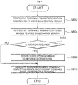
- FIG. 6 is a flowchart illustrating a method for a video call according to the first exemplary embodiment.
- the respective terminals 202 while requesting a video call from the video call control server 204, the respective terminals 202 transmit their own orientation information to the video call control server 204 (S602). At this time, the respective terminals 202 may transmit their own reference aspect ratio information together with the orientation information.
- the reference aspect ratio information is not necessarily transmitted together with the orientation information, and may be transmitted separately from the orientation information, according to an exemplary embodiment.
- the respective terminals 202 transmit images obtained by capturing users to the video call control server 204 (S604).
- the images transmitted to the video call control server 204 may be shown to be rotated by a predetermined angle with respect to a reference orientation according to orientations of the respective terminals 202 when capturing.
- the video call control server 204 checks whether or not there is an image required to be rotated to the reference orientation among the images received from the respective terminals 202 using the orientation information received from the respective terminals 202 (S606).
- the video call control server 204 rotates the image to the reference orientation (S608).
- images required to be rotated to the reference orientation are rotated to the reference orientation, all the images received from the respective terminals 202 are placed in the reference orientation.
- the video call control server 204 generates a combined image by combining the images placed in the reference orientation, and then transmits the combined image to the respective terminals 202 (S610).
- the video call control server 204 when the reference aspect ratio information has been transmitted from the respective terminals 202, the video call control server 204 generates the combined image with an aspect ratio corresponding to the reference aspect ratio information and the orientation information, and then transmits the combined image to the respective terminals 202.
- the terminal 202 may transmit orientation information corresponding to the changed orientation to the video call control server 204 again.
- FIG. 7 is a diagram of a system for a video call according to a second exemplary embodiment.
- a system 700 for a video call includes a plurality of terminals 702 and a video call control server 704. Although four terminals 702 are shown in the drawing, the number of terminals 702 is not limited to four, and two or more terminals 702 may be used.
- Each of the terminals 702 transmits an image captured by the terminal 702 itself to the video call control server 704 while requesting a video call from the video call control server 704. At this time, after checking its own orientation information, each of the terminals 702 rotates the captured image according to the orientation information, and transmits the rotated image to the video call control server 704.
- the orientation information denotes how much a current orientation of the terminal 702 has been rotated with respect to a previously set reference orientation.
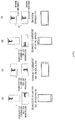
- FIG. 8 is a diagram showing orientations of a terminal according to the second exemplary embodiment rotated by every 90 degrees clockwise with respect to a reference orientation and captured images rotated according to the orientations rotated with respect to the reference orientation.
- a terminal 702 is in a reference orientation.
- the terminal 702 is rotated by 90 degrees clockwise with respect to the reference orientation (rotated by 270 degrees counterclockwise with respect to the reference orientation).
- the terminal 702 is rotated by 180 degrees clockwise with respect to the reference orientation (rotated by 180 degrees counterclockwise with respect to the reference orientation).
- the terminal 702 is rotated by 270 degrees clockwise with respect to the reference orientation (rotated by 90 degrees counterclockwise with respect to the reference orientation).
- a rotation state of the terminal 702 changes from the reference orientation at multiples of 90 degrees (i.e., 0 degree, 90 degrees, 180 degrees, and 270 degrees), and varies according to how much a user rotates the terminal 702.
- a threshold value of a rotation angle of the terminal 702 may be set in advance, and the rotation state may be changed according to the threshold value.
- the terminal 702 transmits a captured image to the video call control server 704 as it is.
- the image is transmitted to the video call control server 704 in a horizontal screen mode.
- the horizontal screen mode denotes a case in which a horizontal screen length (or resolution) of the corresponding image is greater than a vertical screen length
- a vertical screen mode denotes a case in which a vertical screen length (or resolution) of the corresponding image is greater than a horizontal screen length.
- an aspect ratio of the corresponding image may be set to 4:3 or 16:9 in the horizontal screen mode, and set to 3:4 or 9:16 in the vertical screen mode.
- an image captured by the terminal 702 is displayed to be rotated by 90 degrees counterclockwise.
- the terminal 702 rotates the captured image by 90 degrees clockwise and transmits the rotated image to the video call control server 704 so that a video call user is displayed in a reference direction in the captured image.
- the reference direction denotes a direction in which a video call user is displayed in a normal orientation in a captured image (e.g., a orientation in which the video call user's head is directed upward in the captured image).
- the image transmitted to the video call control server 704 is transmitted in the vertical screen mode.
- each terminal 702 checks how much a current orientation of the terminal 702 itself has been rotated with respect to a reference orientation (i.e., checks orientation information), rotates a captured image according to the checked orientation information, and then transmits the rotated image to the video call control server 704.
- a reference orientation i.e., checks orientation information
- each terminal 702 rotates a captured image so that a video call user is displayed in a reference direction in the captured image, even if the terminal 702 has been rotated with respect to the reference orientation, the video call user is displayed in the reference direction in the captured image.
- the terminal 702 may rotate a captured image according to the changed orientation using the same method as described above, and transmit the rotated image to the video call control server 704. Then, the video call control server 704 may analyze the captured image rotated according to the changed orientation, and then generate a combined image corresponding to a current screen mode of the terminal 702.
- a state in which a terminal 702 is horizontally placed is set as a reference orientation
- images in (a) and (c) of FIG. 8 are transmitted in the horizontal screen mode
- images in (b) and (d) of FIG. 8 are transmitted in the vertical screen mode.
- the reference orientation is not limited to the state in which a terminal 702 is horizontally placed.
- the video call control server 704 generates a combined image by combining the respective images transmitted from the respective terminals 702.
- the video call control server 704 may generate the combined image according to a current screen mode (i.e., the horizontal screen mode or the vertical screen mode) of the corresponding terminal 702.
- the video call control server 704 After checking the current screen mode (i.e., the horizontal screen mode or the vertical screen mode) of the corresponding terminal 702 using the respective images transmitted from the respective terminals 702, the video call control server 704 generates a combined image according to the current screen mode of the terminal 702 and transmits the combined image to the terminal 702. At this time, the video call control server 704 may transmit the combined image with an aspect ratio of the terminal 702. In other words, the video call control server 704 may generate a combined image according to the current screen mode and the aspect ratio of the terminal 702, and transmit the combined image to the terminal 702.
- the current screen mode i.e., the horizontal screen mode or the vertical screen mode
- the video call control server 704 may generate a combined image with an aspect ratio of 4:3 in the horizontal screen mode, and transmit the combined image to the terminal 702.
- the video call control server 704 may generate a combined image with an aspect ratio of 9:16 in the vertical screen mode, and transmit the combined image to the terminal 702.
- the video call control server 704 may generate as many combined images as there are types of aspect ratios of the respective terminals 702, and then transmit the combined images according to current screen modes and aspect ratios of the respective terminals 702 to the corresponding terminals 702.
- the video call control server 704 may separately generate a combined image having an aspect ratio of 4:3, a combined image having an aspect ratio of 3:4, a combined image having an aspect ratio of 16:9, and a combined image having an aspect ratio of 9:16, and then transmit the combined images to the respective terminals 702 according to the current screen modes and the aspect ratios of the respective terminals 702.
- the video call control server 704 may analyze the image and check a current screen mode of the terminal 702. At this time, when a current screen mode of a terminal 702 has been changed, the video call control server 704 may generate a combined image according to the changed screen mode, and transmit the combined image to the terminal 702. For example, when a user rotates a terminal 702 from a horizontal orientation to a vertical orientation, the terminal 702 rotates an image according to the rotation direction and transmits the rotated image to the video call control server 704, and the video call control server 704 checks that a screen mode of a received image has been changed from the horizontal screen mode to the vertical screen mode and may generate a combined image according to the changed screen mode.
- each terminal 702 rotates a captured image according to its own orientation information and transmits the rotated image to the video call control server 704, and the video call control server 704 generates a combined image according to a current screen mode of the terminal 702 and transmits the combined image to the terminal 702.
- the video call control server 704 generates a combined image according to a current screen mode of the terminal 702 and transmits the combined image to the terminal 702.
- FIG. 9 is a diagram illustrating a process in which a video call control server according to the second exemplary embodiment generates a combined image using images transmitted from respective terminals.
- a first terminal 702-1 transmits an image captured in a reference orientation to the video call control server 704 as it is, a second terminal 702-2 rotates an image captured in a state in which the second terminal 702-2 has been rotated by 90 degrees clockwise with respect to the reference orientation by 90 degrees clockwise and then transmits the rotated image to the video call control server 704, a third terminal 702-3 rotates an image captured in a state in which the third terminal 702-3 has been rotated by 180 degrees clockwise with respect to the reference orientation by 180 degrees clockwise and then transmits the rotated image to the video call control server 704, and a fourth terminal 702-4 rotates an image captured in a state in which the fourth terminal 702-4 has been rotated by 270 degrees clockwise with respect to the reference orientation by 270 degrees clockwise and then transmits the rotated image to the video call control server 704.
- a state in which the screen of a terminal 702 is horizontally placed is assumed to be the reference orientation.
- images A and C respectively transmitted from the first terminal 702-1 and the third terminal 702-3 are transmitted in the horizontal screen mode
- images B and D respectively transmitted from the second terminal 702-2 and the fourth terminal 702-4 are transmitted in the vertical screen mode.
- an aspect ratio of the respective terminals 702 is assumed to be 16:9.
- the video call control server 704 may check current screen modes and aspect ratios of the first terminal 702-1 and the third terminal 702-3 using the images A and C respectively transmitted from the first terminal 702-1 and the third terminal 702-3. Also, the video call control server 704 may check current screen modes and aspect ratios of the second terminal 702-2 and the fourth terminal 702-4 using the images B and D respectively transmitted from the second terminal 702-2 and the fourth terminal 702-4.
- the video call control server 704 combines the images A, B, C, and D to generate a combined image I' in the horizontal screen mode with an aspect ratio of 16:9, and then transmits the combined image I' to the first terminal 702-1 and the third terminal 702-3. Also, video call control server 704 combines the images A, B, C, and D to generate a combined image I" in the vertical screen mode with a aspect ratio of 9:16, and then transmits the combined image I" to the second terminal 702-2 and the fourth terminal 702-4.
- the respective images A, B, C, and D may be processed with an aspect ratio and/or a screen size different from those of the original images, and combined in the combined image I' and the combined image I".
- an aspect ratio or size may be adjusted to prevent the presence of empty spaces, or partial facial recognition may be performed to cut off a part of an image.
- FIG. 10 is a block diagram showing a constitution of a terminal according to the second exemplary embodiment.
- a terminal 702 includes a capturing unit 1000, a orientation sensor 1002, an image rotator 1004, and a video call unit 1006.
- the capturing unit 1000 captures its front using a camera.
- the capturing unit 1000 may capture a video call user during a video call.
- the orientation sensor 1002 obtains information on a orientation of the terminal 702. In other words, the orientation sensor 1002 senses how much the terminal 702 has been rotated with respect to a previously set reference orientation.
- the orientation sensor 1002 may include, for example, a gyro sensor, a gravity sensor, or so on.
- the image rotator 1004 rotates the image captured by the capturing unit 1000 according to the orientation information on the terminal 702. For example, the image rotator 1004 checks the orientation information obtained by the orientation sensor 1002, and rotates the image captured by the capturing unit 1000 to display the video call user in a reference direction in the image when the terminal 702 has been rotated with respect to the reference orientation. In this case, even when the terminal 702 has been rotated with respect to the reference orientation, the video call user is displayed to be kept in the reference direction in the rotated image.
- the image rotator 1004 delivers the rotated image or the image captured by the capturing unit 1000 to the video call unit 1006. In other words, when the terminal 702 maintains the reference orientation, the image rotator 1004 delivers the image captured by the capturing unit 1000 to the video call unit 1006 as it is.
- the video call unit 1006 requests a video call from the video call control server 704.
- the video call unit 1006 transmits the image captured by the capturing unit 1000 or the image rotated by the image rotator 1004 to the video call control server 704.
- the video call unit 1006 receives a combined image from the video call control server 704.
- FIG. 11 is a block diagram showing a constitution of a video call control server according to the second exemplary embodiment.
- the video call control server 704 includes a communicator 1100, a storage 1102, an image analyzer 1104, and a combined image generator 1106.
- the communicator 1100 performs communication for a video call with respective terminals 702. For example, the communicator 1100 receives captured images from the respective terminals 702. Here, the captured images may be images rotated by image rotators 1004. Also, the communicator 1100 transmits a combined image generated by the combined image generator 1106 to the respective terminals 702.
- the storage 1102 stores captured images of the respective terminals 702 received by the communicator 1100.
- the storage 1102 may store the combined image generated by the combined image generator 1106.
- the storage 1102 may be a buffer that temporarily stores the captured images of the respective terminals 702 and the combined image.
- the image analyzer 1104 analyzes the captured images of the respective terminals 702 received by the communicator 1100, thereby detecting current screen modes and aspect ratios of the respective terminals 702. In other words, the image analyzer 1104 analyzes a horizontal screen length (or resolution) and a vertical screen length (or resolution) of a captured image of each terminal 702, thereby detecting a current screen mode and an aspect ratio of the corresponding terminal 702.
- the combined image generator 1106 generates the combined image by combining the captured images received from the respective terminals 702.
- the combined image generator 1106 may generate a combined image according to a current screen mode (horizontal screen mode or vertical screen mode) of each terminal 702. At this time, the combined image generator 1106 may generate the combined image with an aspect ratio of the terminal 702.
- FIG. 12 is a flowchart illustrating a method for a video call according to the second exemplary embodiment.
- the respective terminals 702 while requesting a video call from the video call control server 704, the respective terminals 702 check their own orientation information (S1202). At this time, the respective terminals 702 may check their own orientation information using a gyro sensor, a gravity sensor, etc. installed therein.
- the respective terminals 702 rotate captured images according to their own orientation information, and transmit the rotated images to the video call control server 704 (S1204).
- the respective terminals 702 may rotate the captured images so that video call users are displayed in a previously set reference direction in the images.
- the video call control server 704 checks current screen modes and aspect ratios of the respective terminals 702 using the images transmitted from the respective terminals 702 (S1206).
- the video call control server 704 generates a combined image according to a current screen mode and an aspect ratio of each terminal 702 using an image transmitted from the terminal 702, and then transmits the combined image to the terminal 702 (S1208).
- the terminal 702 may rotate a captured image according to the changed orientation, and then transmit the rotated image to the video call control server 704. Then, after analyzing the captured image rotated according to the changed orientation, the video call control server 704 may generate a combined image corresponding to a current screen mode of the corresponding terminal 702 and transmit the combined image to the terminal 702.
- exemplary embodiments may include a computer-readable recording medium including a program for performing the methods described herein on a computer.
- the computer-readable recording medium may separately include program commands, local data files, local data structures, etc. or include a combination of them.
- the medium may be specially designed and configured for the present disclosure, or known and available to those of ordinary skill in the field of computer software.
- Examples of the computer-readable recording medium include magnetic media, such as a hard disk, a floppy disk, and a magnetic tape, optical recording media, such as a CD-ROM and a DVD, magnetooptical media, such as a floptical disk, and hardware devices, such as a ROM, a RAM, and a flash memory, specially configured to store and perform program commands.
- Examples of the program commands may include high-level language codes executable by a computer using an interpreter, etc. as well as machine language codes made by compilers.
- a computer such as the one mentioned above, is very familiar to those who practice in these technical arts. Therefore, the discussion herein has avoided obscuring the key features of the exemplary embodiments by purposefully omitting details concerning the manner in which a hardware processor of such a computer system uses the above-identified computer-readable codes and data storage device to carry out the various functions or implement the various units previously mentioned. Likewise, since a person familiar with this field understands that such functions and units may be implemented through various combinations of hardware and/or software, such implementation details are likewise omitted.
Description
- The present disclosure relates to video call technology, and, more particularly, to a system and method, for a video call, that display respective users in the same direction as a reference orientation or a reference posture in a video screen. The invention relates to a system for video call, a method of operating a video call control server, and a method of operating a terminal used in a video call system.
- Recent developments in information and communications technology have allowed a video call as well as a voice call through a portable terminal. In a video call service, users capture their own images using cameras attached to portable terminals and then transmit the images to counterpart portable terminals so that they can talk with each other while looking at their counterparts.
- A video call service can provide a one-to-one video call between a caller and a called party and a group video call. Here, group video calls are mainly made through a control device called a multipoint control unit (MCU). The MCU is a device that receives voice and images transmitted by respective portable terminals, combines the plurality of voices and images into one, and then transmits the combined voice and image data to the respective portable terminals.
-
FIG. 1 is a diagram showing an existing video call system employing an MCU. - Referring to
FIG. 1 , in an existing video call system, since anMCU 20 combines images a, b, c, and d transmitted by respectiveportable terminals portable terminals 11 to 14. The images a to d in the combined image I may have different display orientations according to the various orientations being used by users of therespective terminals 11 to 14during the video call. - For example, when the
portable terminal 11 and the portable terminal 14 are rotated by 90 degrees clockwise with respect to a reference orientation, and capture images, and theportable terminal 12 and theportable terminal 13 capture images in the reference orientation, the images a and d captured by theportable terminal 11 and the portable terminal 14 each are combined by theMCU 20 in their then-active orientation, i.e., rotated by 90 degrees counterclockwise. The images b and c, however, captured by theportable terminal 12 and theportable terminal 13 are each combined by theMCU 20 in their then-active orientation, namely, the reference orientation. - In this case, when users of the respective
portable terminals 11 to 14 look at the combined image I, the images a and d in the combined image I are shown in the orientation rotated by 90 degrees counterclockwise, and thus the viewers see a combined image that looks strange and is hard on the eyes. -
US 2011/0249073 A1 refers to a technique for establishing a video conference during a phone call. A method is provided for initiating a video conference using a first mobile device. The method presents, during an audio call through a wireless communication network with a second device, a selectable user-interface, UI, item on the first mobile device for switching from the audio call to the video conference. The method receives a selection of the selectable UI item. The method initiates the video conference without terminating the audio call. The method terminates the audio call before allowing the first and second devices to present audio and video data exchanged through the video conference. -
US 2009/0309897 A1 refers to a communication terminal and communication system and display method of communication terminal. The communication terminal and the communication system are able to adaptively update sizes and positions of screens in accordance with the situation without operation by a user, and a display method of the communication terminal, which performs processing of individual packets in a linked manner under the control of a display image control portion 306 based on an address of a transmitting side. Based on a sound pressure (volume) of audio information (VoIP) from the same transmitting side address, the terminal etc. calculate the screen sizes for mapping of packets of the video information from the same transmitting side address and corrects the top/bottom of the same screen or displays an instructed animated character based on top/bottom information, instruction information, etc. described in the packets of the control information from the same transmitting side address. -
EP 1 298 925 A2 refers to a moving picture communication method and apparatus. When picture information of a user's party, enlarged and pivoted at an angle of some 90 degrees, is displayed on an image display of a cell-phone type moving picture communication apparatus of a user, which has been pivoted at an angle of nearly 90 degrees in an either rightward or leftward direction of the user's cell-phone type moving picture communication apparatus when the user faces the image display of the user's communication apparatus, then a pivoting unit pivots user's self-picture information in response to pivotal movement of the user's cell-phone type moving picture communication apparatus. The image display has an aspect ratio defined by different vertical and horizontal lengths. An image pick-up unit of the pivoted user's cell-phone type moving picture communication apparatus produces the user's self-picture information. An encoding unit encodes the pivoted user's self-picture information. A transmitting unit transmits the encoded user's self-picture information to a cell-phone type moving picture communication apparatus of the user's party. Since the party's cell-phone type moving picture communication apparatus receives the pivoted user's self-picture information from the user's cell-phone type moving picture communication apparatus, the user's self-picture information properly oriented with respect to the vertical axis of the earth is displayed on the party's cell-phone type moving picture communication apparatus. - It is the object of the present invention to provide an improved terminal and a video call control server that cause each video call user to be displayed as if oriented in a reference direction in a captured image, even when the terminal is rotated, and a system and method for a video call using the terminal and the video call control server.
- This object is solved by the subject matter of the independent claims.
- Preferred embodiments are defined by the dependent claims.
- According to an exemplary embodiment, there is provided a system for video call according to claim 1. According to another exemplary embodiment, there is provided a method of operating a video call control server according to claim 3. According to another exemplary embodiment, there is provided a method of operating a terminal used in a video call system according to claim 5.
- In exemplary embodiments, even when respective terminals capture users in different orientations and perform a video call, it is possible to receive a combined image of respective images in which video call users are all displayed in a reference direction from a video call control server. In this case, the users of the respective terminals can enjoy the video call without viewing other users in an unnatural orientation.
-
-
FIG. 1 is a diagram showing an existing video call system employing a multipoint control unit (MCU). -
FIG. 2 is a diagram of a system for a video call according to a first exemplary embodiment. -
FIG. 3 is a diagram showing orientations of a terminal according to the first exemplary embodiment rotated with respect to a reference orientation. -
FIG. 4 is a diagram illustrating a process in which a video call control server rotates images using orientation information transmitted from respective terminals and then generates a combined image in the system for a video call according to the first exemplary embodiment. -
FIG. 5 is a block diagram showing a constitution of a video call control server according to the first exemplary embodiment. -
FIG. 6 is a flowchart illustrating a method for a video call according to the first exemplary embodiment. -
FIG. 7 is a diagram of a system for a video call according to a second exemplary embodiment. -
FIG. 8 is a diagram showing orientations of a terminal according to the second exemplary embodiment rotated by every 90 degrees clockwise with respect to a reference orientation and captured images rotated according to the orientations rotated with respect to the reference orientation. -
FIG. 9 is a diagram illustrating a process in which a video call control server according to the second exemplary embodiment generates a combined image using images transmitted from respective terminals. -
FIG. 10 is a block diagram showing a constitution of a terminal according to the second exemplary embodiment. -
FIG. 11 is a block diagram showing a constitution of a video call control server according to the second exemplary embodiment. -
FIG. 12 is a flowchart illustrating a method for a video call according to the second exemplary embodiment. - Hereinafter, detailed example embodiments will be described with reference to the accompanying drawings. However, the described embodiments are merely examples and not to be construed as limiting the scope of the present disclosure. It is noted that the "second exemplary embodiment" is not according to the invention and is present for illustration purposes only.
- To avoid obscuring the key points, details familiar to those who work in this field are intentionally omitted. Terminology described below is defined considering functions in the present disclosure and may vary according to a user's or operator's intention or usual practice. Thus, the meanings of the terminology should be interpreted based on the overall context of the present specification.
- The scope of the inventive concept are to be determined with reference to the appended claims, to that end, the following exemplary embodiments are provided only to efficiently describe the inventive concept to those of ordinary skill in the art.
- A system for a video call according to an exemplary embodiment includes one or more terminals that transmit images obtained by capturing or photographing video call users, and a video call control server that generates a combined image by combining the images transmitted by the one or more terminals and transmitting the combined image to the terminals. Here, the respective images are rotated according to information on orientations sensed by the terminals, and combined into the combined image.
- In an exemplary embodiment, the terminal may be configured to transmit the orientation information to the video call control server. In this case, the video call control server may rotate the images received from the terminals to a reference orientation according to the orientation information, and generate the combined image by combining the rotated images.
- The terminals may transmit aspect ratio information on the terminals to the video call control server together with the orientation information. Also, when the orientations of the terminals are changed after the orientation information is transmitted, the terminals may transmit updated orientation information corresponding to the changed orientations to the video call control server.
- In another exemplary embodiment not according to the invention and present for illustration purposes only, the terminals may sense their orientations, rotate captured images to a reference orientation according to information on the sensed orientations, and transmit the rotated images to the video call control server. Also, when the orientations of the terminals are changed after the orientation information is transmitted, the terminals may rotate captured images according to orientation information corresponding to the changed orientations, and transmit the rotated images to the video call control server.
- In this case, the video call control server may check screen modes of the terminals using the images transmitted by the terminals, generate the combined image according to the screen modes, and transmit the combined image to the terminals. Also, the video call control server may check aspect ratios together with the screen modes of the terminals using the images received from the terminals, generate the combined image according to the screen modes and the aspect ratios, and transmit the combined image to the terminals.
- A method for a video call according to exemplary embodiments includes transmitting, at one or more terminals, images obtained by capturing video call users, generating, at a video call control server, a combined image by combining the images transmitted by the one or more terminals, and transmitting, at the video call control server, the combined image to the terminals. The respective images constituting the combined image are rotated according to information on orientations sensed by the terminals, and combined.
- In an exemplary embodiment, transmitting the images may further include transmitting the orientation information on the terminals to the video call control server. In this case, generating the combined image may include rotating the images received from the terminals to a reference orientation according to the received orientation information, and generating the combined image by combining the rotated images.
- In addition, transmitting the images may further include transmitting aspect ratio information on the terminals to the video call control server together with the orientation information.
- Meanwhile, when the orientations of the terminals are changed after transmission of the orientation information, the terminals may transmit orientation information corresponding to the changed orientations to the video call control server.
- In another exemplary embodiment not according to the invention and present for illustration purposes only, transmitting the images may further include sensing orientations of the terminals, and rotating the captured images to a reference orientation according to information on the sensed orientations and transmitting the rotated images to the video call control server. In this case, when the orientations of the terminals are changed after the orientation information is transmitted, the terminals may rotate the captured images according to orientation information corresponding to the changed orientations and transmit the rotated images to the video call control server.
- Generating the combined image may further include checking screen modes of the terminals using the images transmitted by the terminals, and generating the combined image according to the screen modes. Also, generating the combined image may further include checking aspect ratios of the terminals together with the screen modes using the images received from the terminals, and generating the combined image according to the screen modes and the aspect ratios.
- A system for a video call configured as described above according to exemplary embodiments will be described in detail below.
-
FIG. 2 is a diagram of a system for a video call according to a first exemplary embodiment. - Referring to
FIG. 2 , asystem 200 for a video call according to this exemplary embodiment includes a plurality ofterminals 202 and a videocall control server 204. Although fourterminals 202 are shown in the drawing, the number ofterminals 202 is not limited to four, and two ormore terminals 202 may be used. - Each of the
terminals 202 requests a video call from the videocall control server 204. In this embodiment and the following embodiments, theterminals 202 may include all types of terminals such as a portable terminal, a fixed terminal, a wireless terminal, a wired terminal, etc. capable of participating in a video call. For example, a cellular phone such as a smartphone, a personal digital assistant (PDA), a tablet personal computer (PC), a laptop computer, or a desktop computer may be a terminal in the present disclosure. As an example of theterminals 202, a portable terminal in the form of a cellular phone is shown here, but theterminals 202 are not limited to portable terminals in the form of a cellular phone. - Each of the
terminals 202 transmits orientation information about the terminal 202 itself to the videocall control server 204 while requesting the video call from the videocall control server 204. Here, the orientation information is any type of information that can be used to determine how much thecorresponding terminal 202 has been rotated with respect to a reference orientation. -
FIG. 3 is a diagram showing orientations of a terminal according to the first exemplary embodiment rotated with respect to a reference orientation. Referring toFIG. 3 , each terminal 202 may be in a state as shown inFIG. 3 (reference) in which the terminal 202 is in a reference orientation. Likewise, each terminal 202 may be in a state as shown inFIG. 3 (a) in which the terminal 202 is rotated by 90 degrees clockwise with respect to a reference orientation (i.e., rotated by 270 degrees counterclockwise with respect to the reference orientation). Likewise, each terminal 202 may be in a state as shown inFIG. 3 (b) in which the terminal 202 is rotated by 180 degrees clockwise with respect to the reference orientation (rotated by 180 degrees counterclockwise with respect to the reference orientation). Finally, each terminal 202 may be in a state as shown inFIG. 3 (c) in which the terminal 202 is rotated by 270 degrees clockwise with respect to the reference orientation (rotated by 90 degrees counterclockwise with respect to the reference orientation). - Here, the rotation state of the terminal 202 is understood to vary from the reference orientation in multiples of 90 degrees (i.e., 0 degree, 90 degrees, 180 degrees, and 270 degrees), and this rotation state depends upon how much a user rotates the terminal 202. Since it is practically impossible for a human user carrying the terminal 202 in one hand to consistently rotate the terminal 202 at an accurate angle, a threshold value for a rotation angle of the terminal 202 may be set in advance, and the rotation state may be changed according to the threshold value. For example, the rotation state may be set to the reference state when the rotation angle of the terminal 202 is -45 degrees to 45 degrees; rotated by 90 degrees clockwise when the rotation angle is 46 degrees to 135 degrees; rotated by 180 degrees clockwise when the rotation angle is 136 degrees to 225 degrees; and rotated by 270 degrees clockwise when the rotation angle is 226 degrees to 315 degrees.
- The reference orientation of the terminal 202 may vary according to a setting, a communication service provider, etc., of the terminal 202. For example, a state in which the screen of the terminal 202 is horizontally or vertically placed may be determined as the reference orientation.
- In this way, each terminal 202 transmits its own orientation information, dependent on a state in which the terminal 202 is rotated with respect to the reference orientation, to the video
call control server 204. Meanwhile, when its own orientation is changed at a time after a terminal 202 has already transmitted its own orientation information to the videocall control server 204, the terminal 202 again transmits orientation information indicating the changed orientation to the videocall control server 204. - In addition, each terminal 202 may transmit its own reference aspect ratio information to the video
call control server 204. Here, the reference aspect ratio information denotes a width-to-height ratio of thecorresponding terminal 202 in the reference orientation. For example, width-to-height aspect ratios of theterminals 202 may be 4:3 or 16:9 in the reference orientation, and each terminal 202 may transmit such reference aspect ratio information to the videocall control server 204. At this time, each terminal 202 may transmit its own orientation information and reference aspect ratio information using a session initiation protocol (SIP) message. - Each terminal 202 transmits an image obtained by capturing a user to the video
call control server 204. At this time, the image may be shown to be rotated by a predetermined angle with respect to a reference orientation according to a orientation of the terminal 202 when capturing the image. For example, when the terminal 202 is rotated by 90 degrees clockwise with respect to the reference orientation to capture the user, an image obtained by capturing the user is shown to be rotated by 90 degrees counterclockwise with respect to the reference orientation. - When an image transmitted from each terminal 202 has been rotated by the predetermined angle with respect to the reference orientation, the video
call control server 204 rotates the image again to the reference orientation, and then generates a combined image by combining respective images. - Specifically, the video
call control server 204 may check whether or not an image transmitted from each terminal 202 has been rotated by the predetermined angle with respect to the reference orientation using orientation information transmitted from the terminal 202. When it is checked that the image transmitted by the terminal 202 has been rotated by the predetermined angle with respect to the reference orientation, the videocall control server 204 rotates the image again to the reference orientation. For example, when the image transmitted by the terminal 202 has been rotated by 90 degrees counterclockwise with respect to the reference orientation, the videocall control server 204 rotates the image by 90 degrees clockwise (or 270 degrees counterclockwise) to place the image in the reference orientation. - Then, all images transmitted by the
respective terminals 202 are placed in the reference orientation. The videocall control server 204 generates the combined image by combining the images all placed in the reference orientation, and then transmits the combined image to therespective terminals 202. - At this time, when reference aspect ratio information has been transmitted from each terminal 202, the video
call control server 204 generates the combined image with an aspect ratio corresponding to the reference aspect ratio information, and then transmits the combined image to theterminals 202. For example, when an aspect ratio of a terminal 202 is 4:3, the videocall control server 204 generates the combined image with an aspect ratio of 4:3, and then transmits the combined image to the terminal 202. Also, when an aspect ratio of a terminal 202 is 16:9, the videocall control server 204 generates the combined image with an aspect ratio of 16:9, and then transmits the combined image to the terminal 202. - At this time, the video
call control server 204 may separately generate as many combined images according to each of aspect ratios of therespective terminals 202, and then transmit the combined images according to the aspect ratios of therespective terminals 202 to thecorresponding terminals 202. For example, when therespective terminals 202 have two types of aspect ratios of 4:3 and 16:9, the videocall control server 204 may separately generate a combined image having an aspect ratio of 4:3 and a combined image having an aspect ratio of 16:9, and then transmit the combined image having the aspect ratio of 4:3 torespective terminals 202 having the aspect ratio of 4:3 and the combined image having the aspect ratio of 16:9 torespective terminals 202 having the aspect ratio of 16:9. - In addition, according to an exemplary embodiment, the video
call control server 204 checks orientation information on each terminal 202, and then transmits a combined image with an aspect ratio corresponding to a current orientation of the terminal 202 to the terminal 202. For example, when an aspect ratio of a terminal 202 is 4:3, and the terminal 202 is currently in the reference orientation, the videocall control server 204 generates a combined image with an aspect ratio of 4:3 and transmits the combined image to the terminal 202. Also, according to an exemplary embodiment, when an aspect ratio of a terminal 202 is 4:3, and the terminal 202 has been rotated by 90 degrees clockwise with respect to the reference orientation, the videocall control server 204 generates a combined image with an aspect ratio of 3:4 and then transmits the combined image to the terminal 202. - In an exemplary embodiment, each terminal 202 transmits its own orientation information to the video
call control server 204, and the videocall control server 204 rotates an image rotated by a predetermined angle with respect to a reference orientation to the reference orientation again and then generates a combined image so thatrespective terminals 202 can receive the combined image in which respective images are placed in the reference orientation from the videocall control server 204 even when therespective terminals 202 capture users in different orientations and transmit the captured images. In this case, the users of therespective terminals 202 can do a video call without having to view images of other users in an unnatural rotation. -
FIG. 4 is a diagram illustrating a process in which a video call control server rotates images using orientation information transmitted from respective terminals and then generates a combined image in the system for a video call according to the first exemplary embodiment. - Referring to
FIG. 4 , a terminal 202-1 transmits an image A captured in a reference orientation to the videocall control server 204, a terminal 202-2 transmits an image B captured in a state in which the terminal 202-2 has been rotated by 90 degrees clockwise with respect to the reference orientation to the videocall control server 204, a terminal 202-3 transmits an image C captured in a state in which the terminal 202-3 has been rotated by 180 degrees clockwise with respect to the reference orientation to the videocall control server 204, and a terminal 202-4 transmits an image D captured in a state in which the terminal 202-4 has been rotated by 270 degrees clockwise with respect to the reference orientation to the videocall control server 204. In this case, the image B, the image C, and the image D are shown to be rotated by 90 degrees, 180 degrees, and 270 degrees counterclockwise with respect to the reference orientation, respectively. Here, the respective terminals 202-1, 202-2, 202-3 and 202-4 may transmit their own orientation information and reference aspect ratio information to the videocall control server 204 in advance of the images A, B, C and D. - Then, the video
call control server 204 finds that the image B, the image C, and the image D have been rotated by 90 degrees, 180 degrees, and 270 degrees counterclockwise with respect to the reference orientation respectively from the orientation information received from the respective terminals 202-1, 202-2, 202-3, and 202-4. In this case, the videocall control server 204 rotates the image B, the image C, and the image D by 90 degrees, 180 degrees, and 270 degrees clockwise respectively to place them in the reference orientation, generates a combined image by combining the images A, B, C, and D, and then transmits the combined image to the respective terminals 202-1, 202-2, 202-3, and 202-4. - At this time, assuming that an aspect ratio of the respective terminals 202-1, 202-2, 202-3, and 202-4 is 16:9, a current aspect ratio of the terminals 202-1 and 202-3 is 16:9, and thus the video
call control server 204 generates a combined image I' with an aspect ratio of 16:9, and then transmits the combined image I' to the terminals 202-1 and 202-3. On the other hand, a current aspect ratio of the terminals 202-2 and 202-4 is 9:16, and thus the videocall control server 204 generates a combined image I" with an aspect ratio of 9:16, and then transmits the combined image I" to the terminals 202-2 and 202-4. - In the combined image I' and the combined image I", the respective images A, B, C, and D are shown to have the same aspect ratios as the original images. However, the present disclosure is not limited to this, and the respective images A, B, C, and D may be processed with at least one of a different aspect ratio and screen size than those of the original images and combined in the combined image I' and the combined image I". For example, when the respective images A, B, C, and D have the same aspect ratios as the original images in the combine image I', there are empty spaces on the left and right of the images B and D in the combined image I', and there are empty spaces above and under the images A and C in the combined image I". To prevent the presence of empty spaces above and under each image or on the left and right of the image in the combined images I' and I", aspect ratios and screen sizes of images may be adjusted and combined. For example, in the combined image I', the upper and lower sides of the images B and D may be cut off, and the sizes of the images B and D may be adjusted so that faces of video call users occupy the entire corresponding screen. Also, in the combined image I", the left and right sides of the images A and C may be cut off. In addition, when a part of an image is cut off so as to be combined into a combined image, a face of a person in the image may be recognized so as not to cut off part of the face. Since image recognition technology is well known in the technical field to which the present disclosure pertains, detailed description thereof will be omitted.
-
FIG. 5 is a block diagram showing a constitution of a video call control server according to the first exemplary embodiment. Referring toFIG. 5 , the videocall control server 204 includes acommunicator 500, astorage 502, animage rotator 504, and a combinedimage generator 506. - The
communicator 500 receives orientation information, and images obtained by capturing users of thecorresponding terminals 202, from therespective terminals 202. Thecommunicator 500 may also receive reference aspect ratio information from therespective terminals 202. Also, thecommunicator 500 transmits a combined image, generated by the combinedimage generator 506, to therespective terminals 202. - The
storage 502 stores the orientation information and captured images of therespective terminals 202 received by thecommunicator 500. Thestorage 502 may also store the reference aspect ratio information on therespective terminals 202 received by thecommunicator 500. - The
image rotator 504 checks whether or not there is an image required to be rotated to a reference orientation, among the images transmitted by therespective terminals 202, based on the orientation information on therespective terminals 202. When there is an image required to be rotated to the reference orientation, theimage rotator 504 rotates the image to place the image in the reference orientation. - The combined
image generator 506 generates a combined image by combining images that are not required to be rotated to the reference orientation (i.e., images having been already placed in the reference orientation) among the images received from therespective terminals 202 and images that have been rotated to the reference orientation by theimage rotator 504 among the images received from therespective terminals 202. At this time, the combinedimage generator 506 may generate the combined image with an aspect ratio corresponding to the reference aspect ratio information and the orientation information transmitted by therespective terminals 202. -
FIG. 6 is a flowchart illustrating a method for a video call according to the first exemplary embodiment. - Referring to
FIG. 6 , while requesting a video call from the videocall control server 204, therespective terminals 202 transmit their own orientation information to the video call control server 204 (S602). At this time, therespective terminals 202 may transmit their own reference aspect ratio information together with the orientation information. However, the reference aspect ratio information is not necessarily transmitted together with the orientation information, and may be transmitted separately from the orientation information, according to an exemplary embodiment. - Next, the
respective terminals 202 transmit images obtained by capturing users to the video call control server 204 (S604). At this time, the images transmitted to the videocall control server 204 may be shown to be rotated by a predetermined angle with respect to a reference orientation according to orientations of therespective terminals 202 when capturing. - Next, the video
call control server 204 checks whether or not there is an image required to be rotated to the reference orientation among the images received from therespective terminals 202 using the orientation information received from the respective terminals 202 (S606). - When it is checked in S606 that there is an image required to be rotated to the reference orientation, the video
call control server 204 rotates the image to the reference orientation (S608). When images required to be rotated to the reference orientation are rotated to the reference orientation, all the images received from therespective terminals 202 are placed in the reference orientation. - Next, the video
call control server 204 generates a combined image by combining the images placed in the reference orientation, and then transmits the combined image to the respective terminals 202 (S610). Here, when the reference aspect ratio information has been transmitted from therespective terminals 202, the videocall control server 204 generates the combined image with an aspect ratio corresponding to the reference aspect ratio information and the orientation information, and then transmits the combined image to therespective terminals 202. - Meanwhile, when its own orientation is changed after each terminal 202 transmits its own orientation information to the video
call control server 204, the terminal 202 may transmit orientation information corresponding to the changed orientation to the videocall control server 204 again. -
FIG. 7 is a diagram of a system for a video call according to a second exemplary embodiment. - Referring to
FIG. 7 , asystem 700 for a video call according to the second exemplary embodiment includes a plurality ofterminals 702 and a videocall control server 704. Although fourterminals 702 are shown in the drawing, the number ofterminals 702 is not limited to four, and two ormore terminals 702 may be used. - Each of the
terminals 702 transmits an image captured by the terminal 702 itself to the videocall control server 704 while requesting a video call from the videocall control server 704. At this time, after checking its own orientation information, each of theterminals 702 rotates the captured image according to the orientation information, and transmits the rotated image to the videocall control server 704. Here, the orientation information denotes how much a current orientation of the terminal 702 has been rotated with respect to a previously set reference orientation. -
FIG. 8 is a diagram showing orientations of a terminal according to the second exemplary embodiment rotated by every 90 degrees clockwise with respect to a reference orientation and captured images rotated according to the orientations rotated with respect to the reference orientation. - Referring to
FIG. 8 (a) , a terminal 702 is in a reference orientation. InFIG. 8 (b) theterminal 702 is rotated by 90 degrees clockwise with respect to the reference orientation (rotated by 270 degrees counterclockwise with respect to the reference orientation). InFIG. 8 (c) , the terminal 702 is rotated by 180 degrees clockwise with respect to the reference orientation (rotated by 180 degrees counterclockwise with respect to the reference orientation). InFIG. 8 (d) theterminal 702 is rotated by 270 degrees clockwise with respect to the reference orientation (rotated by 90 degrees counterclockwise with respect to the reference orientation). - In other words, a rotation state of the terminal 702 changes from the reference orientation at multiples of 90 degrees (i.e., 0 degree, 90 degrees, 180 degrees, and 270 degrees), and varies according to how much a user rotates the terminal 702. As described in the first exemplary embodiment, since it is practically impossible for a user to consistently rotate the terminal 702 by hand at an accurate angle, a threshold value of a rotation angle of the terminal 702 may be set in advance, and the rotation state may be changed according to the threshold value.
- As shown in (a) of
FIG. 8 , when the terminal 702 is in the reference orientation, the terminal 702 transmits a captured image to the videocall control server 704 as it is. Here, the image is transmitted to the videocall control server 704 in a horizontal screen mode. In exemplary embodiments, the horizontal screen mode denotes a case in which a horizontal screen length (or resolution) of the corresponding image is greater than a vertical screen length, and a vertical screen mode denotes a case in which a vertical screen length (or resolution) of the corresponding image is greater than a horizontal screen length. For example, an aspect ratio of the corresponding image may be set to 4:3 or 16:9 in the horizontal screen mode, and set to 3:4 or 9:16 in the vertical screen mode. - As shown in (b) of
FIG. 8 , when the terminal 702 has been rotated by 90 degrees clockwise with respect to the reference orientation, an image captured by the terminal 702 is displayed to be rotated by 90 degrees counterclockwise. At this time, the terminal 702 rotates the captured image by 90 degrees clockwise and transmits the rotated image to the videocall control server 704 so that a video call user is displayed in a reference direction in the captured image. The reference direction denotes a direction in which a video call user is displayed in a normal orientation in a captured image (e.g., a orientation in which the video call user's head is directed upward in the captured image). Here, the image transmitted to the videocall control server 704 is transmitted in the vertical screen mode. - As shown in (c) of
FIG. 8 , when the terminal 702 has been rotated by 180 degrees clockwise with respect to the reference orientation, an image captured by the terminal 702 is displayed to be rotated by 180 degrees counterclockwise. At this time, the terminal 702 rotates the captured image by 180 degrees clockwise and transmits the rotated image to the videocall control server 704 so that the video call user is displayed in the reference direction in the captured image. Here, the image transmitted to the videocall control server 704 is transmitted in the horizontal screen mode. - As shown in (d) of
FIG. 8 , when the terminal 702 has been rotated by 270 degrees clockwise with respect to the reference orientation, an image captured by the terminal 702 is displayed to be rotated by 270 degrees counterclockwise. At this time, the terminal 702 rotates the captured image by 270 degrees clockwise and transmits the rotated image to the videocall control server 704 so that the video call user is displayed in the reference direction in the captured image. Here, the image transmitted to the videocall control server 704 is transmitted in the vertical screen mode. - As described above, each terminal 702 checks how much a current orientation of the terminal 702 itself has been rotated with respect to a reference orientation (i.e., checks orientation information), rotates a captured image according to the checked orientation information, and then transmits the rotated image to the video
call control server 704. Here, when each terminal 702 rotates a captured image so that a video call user is displayed in a reference direction in the captured image, even if the terminal 702 has been rotated with respect to the reference orientation, the video call user is displayed in the reference direction in the captured image. - When its own orientation is changed after each terminal 702 transmits a captured image, the terminal 702 may rotate a captured image according to the changed orientation using the same method as described above, and transmit the rotated image to the video
call control server 704. Then, the videocall control server 704 may analyze the captured image rotated according to the changed orientation, and then generate a combined image corresponding to a current screen mode of the terminal 702. - Here, since a state in which a terminal 702 is horizontally placed is set as a reference orientation, images in (a) and (c) of
FIG. 8 are transmitted in the horizontal screen mode, and images in (b) and (d) ofFIG. 8 are transmitted in the vertical screen mode. However, the reference orientation is not limited to the state in which a terminal 702 is horizontally placed. - Next, the video
call control server 704 generates a combined image by combining the respective images transmitted from therespective terminals 702. At this time, the videocall control server 704 may generate the combined image according to a current screen mode (i.e., the horizontal screen mode or the vertical screen mode) of thecorresponding terminal 702. - Specifically, after checking the current screen mode (i.e., the horizontal screen mode or the vertical screen mode) of the
corresponding terminal 702 using the respective images transmitted from therespective terminals 702, the videocall control server 704 generates a combined image according to the current screen mode of the terminal 702 and transmits the combined image to the terminal 702. At this time, the videocall control server 704 may transmit the combined image with an aspect ratio of the terminal 702. In other words, the videocall control server 704 may generate a combined image according to the current screen mode and the aspect ratio of the terminal 702, and transmit the combined image to the terminal 702. - For example, when a current screen mode of a terminal 702 is the horizontal screen mode, and an aspect ratio is 4:3, the video
call control server 704 may generate a combined image with an aspect ratio of 4:3 in the horizontal screen mode, and transmit the combined image to the terminal 702. Also, when a current screen mode of a terminal 702 is the vertical screen mode, and an aspect ratio is 16:9, the videocall control server 704 may generate a combined image with an aspect ratio of 9:16 in the vertical screen mode, and transmit the combined image to the terminal 702. - At this time, the video
call control server 704 may generate as many combined images as there are types of aspect ratios of therespective terminals 702, and then transmit the combined images according to current screen modes and aspect ratios of therespective terminals 702 to thecorresponding terminals 702. For example, when therespective terminals 702 have two types of aspect ratios of 4:3 and 16:9, the videocall control server 704 may separately generate a combined image having an aspect ratio of 4:3, a combined image having an aspect ratio of 3:4, a combined image having an aspect ratio of 16:9, and a combined image having an aspect ratio of 9:16, and then transmit the combined images to therespective terminals 702 according to the current screen modes and the aspect ratios of therespective terminals 702. - Every time an image is transmitted from each terminal 702 (or periodically), the video
call control server 704 may analyze the image and check a current screen mode of the terminal 702. At this time, when a current screen mode of a terminal 702 has been changed, the videocall control server 704 may generate a combined image according to the changed screen mode, and transmit the combined image to the terminal 702. For example, when a user rotates a terminal 702 from a horizontal orientation to a vertical orientation, the terminal 702 rotates an image according to the rotation direction and transmits the rotated image to the videocall control server 704, and the videocall control server 704 checks that a screen mode of a received image has been changed from the horizontal screen mode to the vertical screen mode and may generate a combined image according to the changed screen mode. - In this exemplary embodiment, each terminal 702 rotates a captured image according to its own orientation information and transmits the rotated image to the video
call control server 704, and the videocall control server 704 generates a combined image according to a current screen mode of the terminal 702 and transmits the combined image to the terminal 702. Thus, even whenrespective terminals 702 capture their users in different orientations to perform a video call, it is possible to receive a combined image in which the video call users are displayed in a reference direction from the videocall control server 704. In this case, the users of therespective terminals 702 can enjoy the video call without having to view other users in an unnatural orientation. -
FIG. 9 is a diagram illustrating a process in which a video call control server according to the second exemplary embodiment generates a combined image using images transmitted from respective terminals. - Referring to
FIG. 9 , a first terminal 702-1 transmits an image captured in a reference orientation to the videocall control server 704 as it is, a second terminal 702-2 rotates an image captured in a state in which the second terminal 702-2 has been rotated by 90 degrees clockwise with respect to the reference orientation by 90 degrees clockwise and then transmits the rotated image to the videocall control server 704, a third terminal 702-3 rotates an image captured in a state in which the third terminal 702-3 has been rotated by 180 degrees clockwise with respect to the reference orientation by 180 degrees clockwise and then transmits the rotated image to the videocall control server 704, and a fourth terminal 702-4 rotates an image captured in a state in which the fourth terminal 702-4 has been rotated by 270 degrees clockwise with respect to the reference orientation by 270 degrees clockwise and then transmits the rotated image to the videocall control server 704. - Here, a state in which the screen of a terminal 702 is horizontally placed is assumed to be the reference orientation. In this case, images A and C respectively transmitted from the first terminal 702-1 and the third terminal 702-3 are transmitted in the horizontal screen mode, and images B and D respectively transmitted from the second terminal 702-2 and the fourth terminal 702-4 are transmitted in the vertical screen mode. Also, an aspect ratio of the
respective terminals 702 is assumed to be 16:9. - Then, the video
call control server 704 may check current screen modes and aspect ratios of the first terminal 702-1 and the third terminal 702-3 using the images A and C respectively transmitted from the first terminal 702-1 and the third terminal 702-3. Also, the videocall control server 704 may check current screen modes and aspect ratios of the second terminal 702-2 and the fourth terminal 702-4 using the images B and D respectively transmitted from the second terminal 702-2 and the fourth terminal 702-4. - In this case, the video
call control server 704 combines the images A, B, C, and D to generate a combined image I' in the horizontal screen mode with an aspect ratio of 16:9, and then transmits the combined image I' to the first terminal 702-1 and the third terminal 702-3. Also, videocall control server 704 combines the images A, B, C, and D to generate a combined image I" in the vertical screen mode with a aspect ratio of 9:16, and then transmits the combined image I" to the second terminal 702-2 and the fourth terminal 702-4. - As described in the first exemplary embodiment, the respective images A, B, C, and D may be processed with an aspect ratio and/or a screen size different from those of the original images, and combined in the combined image I' and the combined image I". For example, as in the first exemplary embodiment, an aspect ratio or size may be adjusted to prevent the presence of empty spaces, or partial facial recognition may be performed to cut off a part of an image.
-
FIG. 10 is a block diagram showing a constitution of a terminal according to the second exemplary embodiment. - Referring to
FIG. 10 , a terminal 702 according to the second exemplary embodiment includes acapturing unit 1000, aorientation sensor 1002, animage rotator 1004, and avideo call unit 1006. - The
capturing unit 1000 captures its front using a camera. For example, thecapturing unit 1000 may capture a video call user during a video call. - The
orientation sensor 1002 obtains information on a orientation of the terminal 702. In other words, theorientation sensor 1002 senses how much the terminal 702 has been rotated with respect to a previously set reference orientation. Theorientation sensor 1002 may include, for example, a gyro sensor, a gravity sensor, or so on. - The
image rotator 1004 rotates the image captured by thecapturing unit 1000 according to the orientation information on theterminal 702. For example, theimage rotator 1004 checks the orientation information obtained by theorientation sensor 1002, and rotates the image captured by thecapturing unit 1000 to display the video call user in a reference direction in the image when the terminal 702 has been rotated with respect to the reference orientation. In this case, even when the terminal 702 has been rotated with respect to the reference orientation, the video call user is displayed to be kept in the reference direction in the rotated image. - The
image rotator 1004 delivers the rotated image or the image captured by thecapturing unit 1000 to thevideo call unit 1006. In other words, when the terminal 702 maintains the reference orientation, theimage rotator 1004 delivers the image captured by thecapturing unit 1000 to thevideo call unit 1006 as it is. - The
video call unit 1006 requests a video call from the videocall control server 704. Thevideo call unit 1006 transmits the image captured by thecapturing unit 1000 or the image rotated by theimage rotator 1004 to the videocall control server 704. Thevideo call unit 1006 receives a combined image from the videocall control server 704. -
FIG. 11 is a block diagram showing a constitution of a video call control server according to the second exemplary embodiment. Referring toFIG. 11 , the videocall control server 704 includes acommunicator 1100, astorage 1102, animage analyzer 1104, and a combinedimage generator 1106. - The
communicator 1100 performs communication for a video call withrespective terminals 702. For example, thecommunicator 1100 receives captured images from therespective terminals 702. Here, the captured images may be images rotated byimage rotators 1004. Also, thecommunicator 1100 transmits a combined image generated by the combinedimage generator 1106 to therespective terminals 702. - The
storage 1102 stores captured images of therespective terminals 702 received by thecommunicator 1100. Thestorage 1102 may store the combined image generated by the combinedimage generator 1106. In this case, thestorage 1102 may be a buffer that temporarily stores the captured images of therespective terminals 702 and the combined image. - The
image analyzer 1104 analyzes the captured images of therespective terminals 702 received by thecommunicator 1100, thereby detecting current screen modes and aspect ratios of therespective terminals 702. In other words, theimage analyzer 1104 analyzes a horizontal screen length (or resolution) and a vertical screen length (or resolution) of a captured image of each terminal 702, thereby detecting a current screen mode and an aspect ratio of thecorresponding terminal 702. - The combined
image generator 1106 generates the combined image by combining the captured images received from therespective terminals 702. The combinedimage generator 1106 may generate a combined image according to a current screen mode (horizontal screen mode or vertical screen mode) of each terminal 702. At this time, the combinedimage generator 1106 may generate the combined image with an aspect ratio of the terminal 702. -
FIG. 12 is a flowchart illustrating a method for a video call according to the second exemplary embodiment. Referring toFIG. 12 , while requesting a video call from the videocall control server 704, therespective terminals 702 check their own orientation information (S1202). At this time, therespective terminals 702 may check their own orientation information using a gyro sensor, a gravity sensor, etc. installed therein. - Next, the
respective terminals 702 rotate captured images according to their own orientation information, and transmit the rotated images to the video call control server 704 (S1204). At this time, therespective terminals 702 may rotate the captured images so that video call users are displayed in a previously set reference direction in the images. - Next, the video
call control server 704 checks current screen modes and aspect ratios of therespective terminals 702 using the images transmitted from the respective terminals 702 (S1206). - Next, the video
call control server 704 generates a combined image according to a current screen mode and an aspect ratio of each terminal 702 using an image transmitted from the terminal 702, and then transmits the combined image to the terminal 702 (S1208). - Meanwhile, when a orientation of a given
terminal 702 is changed during a video call, the terminal 702 may rotate a captured image according to the changed orientation, and then transmit the rotated image to the videocall control server 704. Then, after analyzing the captured image rotated according to the changed orientation, the videocall control server 704 may generate a combined image corresponding to a current screen mode of thecorresponding terminal 702 and transmit the combined image to the terminal 702. - Meanwhile, exemplary embodiments may include a computer-readable recording medium including a program for performing the methods described herein on a computer. The computer-readable recording medium may separately include program commands, local data files, local data structures, etc. or include a combination of them. The medium may be specially designed and configured for the present disclosure, or known and available to those of ordinary skill in the field of computer software. Examples of the computer-readable recording medium include magnetic media, such as a hard disk, a floppy disk, and a magnetic tape, optical recording media, such as a CD-ROM and a DVD, magnetooptical media, such as a floptical disk, and hardware devices, such as a ROM, a RAM, and a flash memory, specially configured to store and perform program commands. Examples of the program commands may include high-level language codes executable by a computer using an interpreter, etc. as well as machine language codes made by compilers. A computer, such as the one mentioned above, is very familiar to those who practice in these technical arts. Therefore, the discussion herein has avoided obscuring the key features of the exemplary embodiments by purposefully omitting details concerning the manner in which a hardware processor of such a computer system uses the above-identified computer-readable codes and data storage device to carry out the various functions or implement the various units previously mentioned. Likewise, since a person familiar with this field understands that such functions and units may be implemented through various combinations of hardware and/or software, such implementation details are likewise omitted.
- It will be apparent to those skilled in the art that various modifications can be made to the above-described exemplary embodiments without departing from the scope of the present disclosure.
- Thus, it is intended that the present disclosure covers all such modifications provided they come within the scope of the appended claims.
-
- 200, 700:
- system for video call
- 202, 702:
- terminal
- 204, 704:
- video call control server
- 500:
- communicator
- 502:
- storage
- 504:
- image rotator
- 506:
- combined image generator
- 1000:
- capturing unit
- 1002:
- orientation sensor
- 1004:
- image rotator
- 1006:
- video call unit
- 1100:
- communicator
- 1102:
- storage
- 1104:
- image analyzer
- 1106:
- combined image generator
Claims (5)
- A system for video call, comprising:at least two terminals (202) configured to transmit respective orientation information, reference aspect ratio information, and original images obtained by capturing the corresponding video call users; the reference aspect ratio information denoting a width-to-height ratio of the corresponding terminal (202) in a reference orientation, wherein the reference orientation is determined as an orientation of the terminal (202) being horizontal or vertical; anda video call control server (204) configured to check whether or not an image transmitted from each terminal (202) has been rotated by a predetermined angle with respect to the reference orientation using the orientation information transmitted from the terminal (202), and if the check leads to a result that the image transmitted by the terminal (202) has been rotated by the predetermined angle with respect to the reference orientation, the video call control server (204) rotates the image again to the reference orientation, generates a combined image by using all images transmitted by the respective terminals (202) and transmits a combined image to the respective terminals (202), wherein, when the reference aspect ratio information has been transmitted from each of the terminals (202), the video call control server (204) is further configured to generate the combined image with a respective aspect ratio corresponding to the reference aspect ratio information, and then to transmit the combined image to the terminals (202).
- The system of claim 1, wherein, when the orientation of the at least two terminals (202) are changed after transmission of the orientation information, subsequent orientation information, corresponding to the changed orientation, is transmitted to the video call control server (204).
- A method of operating a video call control server, comprising the steps of:receiving (S602), by a communicator (500), respective orientation information, reference aspect ratio information, of at least two terminals (202) and original images obtained by capturing the corresponding video call users from the at least two terminals; the reference aspect ratio information denoting a width-to-height ratio of the corresponding terminal (202) in a reference orientation, wherein the reference orientation is determined as an orientation of the terminal (202) being horizontal or vertical;checking whether or not an image transmitted from each terminal (202) has been rotated by a predetermined angle with respect to the reference orientation using the orientation information transmitted from the terminal (202), and if the check leads to a result that the image transmitted by the terminal (202) has been rotated by the predetermined angle with respect to the reference orientation, rotating (S608), by an image rotator, one or more of the original images required to be rotated to a reference orientation according to the orientation information among the original images received by the communicator (500) to provide rotated images;generating, by a combined image generator (506), a combined image by combining, with a respective aspect ratio corresponding to the received reference aspect ratio information, the original images not required to be rotated to the reference orientation and the rotated images; andtransmitting, by the communicator (500), the combined image to the at least two terminals.
- The method of claim 3, further comprising generating, by the combined image generator (506), the combined image according to the reference aspect ratio information and the orientation information.
- A method of operating a terminal used in a video call system, comprising the steps of:generating captured video images by capturing a video call user, and sensing orientation information with respect to a previously set reference orientation, wherein the reference orientation is determined as an orientation of the terminal (202) being horizontal or vertical,wherein during capturing, the video images are rotated with respect to the set reference orientation due to the orientation of the terminal;transmitting to a video call control server the orientation information and reference aspect ratio information in advance to the rotated video images, the reference aspect ratio information denoting a width-to-height ratio of the terminal (202) in the reference orientation;receiving combined images with the aspect ratio of the terminal (202) from the video call control server; anddisplaying the combined images with the aspect ratio of the terminal (202).
Applications Claiming Priority (4)
| Application Number | Priority Date | Filing Date | Title |
|---|---|---|---|
| KR20120011184 | 2012-02-03 | ||
| KR1020120135149A KR101965310B1 (en) | 2012-11-27 | 2012-11-27 | Terminals, server for controlling video calling, system and method for video calling using the same |
| KR1020130009383A KR101293063B1 (en) | 2012-02-03 | 2013-01-28 | Terminals, server for controlling video calling, system and method for video calling using the same |
| PCT/KR2013/000703 WO2013115541A1 (en) | 2012-02-03 | 2013-01-29 | Terminal, image communication control server, and system and method for image communication using same |
Publications (3)
| Publication Number | Publication Date |
|---|---|
| EP2811739A1 EP2811739A1 (en) | 2014-12-10 |
| EP2811739A4 EP2811739A4 (en) | 2016-01-20 |
| EP2811739B1 true EP2811739B1 (en) | 2021-11-24 |
Family
ID=51640981
Family Applications (1)
| Application Number | Title | Priority Date | Filing Date |
|---|---|---|---|
| EP13743668.9A Active EP2811739B1 (en) | 2012-02-03 | 2013-01-29 | Terminal, image communication control server, and system and method for image communication using same |
Country Status (4)
| Country | Link |
|---|---|
| US (1) | US9307194B2 (en) |
| EP (1) | EP2811739B1 (en) |
| CN (1) | CN104094593B (en) |
| WO (1) | WO2013115541A1 (en) |
Families Citing this family (24)
| Publication number | Priority date | Publication date | Assignee | Title |
|---|---|---|---|---|
| US9190110B2 (en) | 2009-05-12 | 2015-11-17 | JBF Interlude 2009 LTD | System and method for assembling a recorded composition |
| US11232458B2 (en) | 2010-02-17 | 2022-01-25 | JBF Interlude 2009 LTD | System and method for data mining within interactive multimedia |
| US9741150B2 (en) | 2013-07-25 | 2017-08-22 | Duelight Llc | Systems and methods for displaying representative images |
| US9653115B2 (en) | 2014-04-10 | 2017-05-16 | JBF Interlude 2009 LTD | Systems and methods for creating linear video from branched video |
| US9792957B2 (en) | 2014-10-08 | 2017-10-17 | JBF Interlude 2009 LTD | Systems and methods for dynamic video bookmarking |
| US11412276B2 (en) | 2014-10-10 | 2022-08-09 | JBF Interlude 2009 LTD | Systems and methods for parallel track transitions |
| KR102373170B1 (en) * | 2015-01-07 | 2022-03-11 | 삼성전자주식회사 | A mehtod for simultaneously displaying one or more items and an electronic device therefor |
| CN105025243B (en) * | 2015-06-30 | 2018-09-28 | 上海众源网络有限公司 | A kind of video call method and device |
| US10460765B2 (en) | 2015-08-26 | 2019-10-29 | JBF Interlude 2009 LTD | Systems and methods for adaptive and responsive video |
| US11164548B2 (en) | 2015-12-22 | 2021-11-02 | JBF Interlude 2009 LTD | Intelligent buffering of large-scale video |
| US11128853B2 (en) | 2015-12-22 | 2021-09-21 | JBF Interlude 2009 LTD | Seamless transitions in large-scale video |
| US11856271B2 (en) | 2016-04-12 | 2023-12-26 | JBF Interlude 2009 LTD | Symbiotic interactive video |
| CN105959612A (en) * | 2016-04-22 | 2016-09-21 | 惠州Tcl移动通信有限公司 | Method and system for automatically correcting frame angle in mobile terminal video communication |
| US11050809B2 (en) | 2016-12-30 | 2021-06-29 | JBF Interlude 2009 LTD | Systems and methods for dynamic weighting of branched video paths |
| CN107147927B (en) * | 2017-04-14 | 2020-04-03 | 北京小米移动软件有限公司 | Live broadcast method and device based on live broadcast wheat connection |
| US10257578B1 (en) | 2018-01-05 | 2019-04-09 | JBF Interlude 2009 LTD | Dynamic library display for interactive videos |
| CN108235090B (en) * | 2018-01-22 | 2021-09-17 | 广州市千钧网络科技有限公司 | Method and device for adjusting picture angle |
| US11601721B2 (en) | 2018-06-04 | 2023-03-07 | JBF Interlude 2009 LTD | Interactive video dynamic adaptation and user profiling |
| US20200296462A1 (en) | 2019-03-11 | 2020-09-17 | Wci One, Llc | Media content presentation |
| US11490047B2 (en) | 2019-10-02 | 2022-11-01 | JBF Interlude 2009 LTD | Systems and methods for dynamically adjusting video aspect ratios |
| US11245961B2 (en) | 2020-02-18 | 2022-02-08 | JBF Interlude 2009 LTD | System and methods for detecting anomalous activities for interactive videos |
| KR20210119644A (en) * | 2020-03-25 | 2021-10-06 | 삼성전자주식회사 | Method for controlling video call and electronic device thereof |
| US11882337B2 (en) | 2021-05-28 | 2024-01-23 | JBF Interlude 2009 LTD | Automated platform for generating interactive videos |
| US11934477B2 (en) | 2021-09-24 | 2024-03-19 | JBF Interlude 2009 LTD | Video player integration within websites |
Citations (1)
| Publication number | Priority date | Publication date | Assignee | Title |
|---|---|---|---|---|
| EP1601196A1 (en) * | 2004-05-21 | 2005-11-30 | Polycom, Inc. | Method and systems for preparing video communication image for wide screen display |
Family Cites Families (15)
| Publication number | Priority date | Publication date | Assignee | Title |
|---|---|---|---|---|
| JPH08336069A (en) * | 1995-04-13 | 1996-12-17 | Eastman Kodak Co | Electronic still camera |
| JP2001054084A (en) * | 1999-08-09 | 2001-02-23 | Matsushita Electric Ind Co Ltd | Video telephone system |
| JP2001197462A (en) * | 2000-01-17 | 2001-07-19 | Nec Corp | Visual telephone equipment and visual telephone system provided with the same |
| JP2003111040A (en) * | 2001-09-28 | 2003-04-11 | Matsushita Electric Ind Co Ltd | Moving picture communication method and moving picture communication equipment |
| KR100619811B1 (en) * | 2003-09-06 | 2006-09-08 | 엘지전자 주식회사 | Picture auto-reverse apparatus for mobile terminal with camera |
| JP4741261B2 (en) * | 2005-03-11 | 2011-08-03 | 株式会社日立製作所 | Video conferencing system, program and conference terminal |
| WO2007063922A1 (en) * | 2005-11-29 | 2007-06-07 | Kyocera Corporation | Communication terminal and communication system, and display method of communication terminal |
| JP4997783B2 (en) * | 2006-02-15 | 2012-08-08 | 富士ゼロックス株式会社 | Electronic conference system, electronic conference support program, electronic conference control device, information terminal device, electronic conference support method |
| JP2009194857A (en) * | 2008-02-18 | 2009-08-27 | Sharp Corp | Communication conference system, communication apparatus, communication conference method, and computer program |
| JP2010239327A (en) * | 2009-03-31 | 2010-10-21 | Brother Ind Ltd | Conference device, conference support method, and conference support program |
| CN102215373B (en) * | 2010-04-07 | 2014-12-24 | 苹果公司 | In conference display adjustments |
| US8744420B2 (en) | 2010-04-07 | 2014-06-03 | Apple Inc. | Establishing a video conference during a phone call |
| CA2754841C (en) * | 2010-10-12 | 2016-11-01 | Research In Motion Limited | Method and apparatus for image orientation indication and correction |
| US20130106988A1 (en) * | 2011-10-28 | 2013-05-02 | Joseph Davis | Compositing of videoconferencing streams |
| US9137488B2 (en) * | 2012-10-26 | 2015-09-15 | Google Inc. | Video chat encoding pipeline |
-
2013
- 2013-01-29 CN CN201380007775.5A patent/CN104094593B/en active Active
- 2013-01-29 EP EP13743668.9A patent/EP2811739B1/en active Active
- 2013-01-29 US US14/122,912 patent/US9307194B2/en active Active
- 2013-01-29 WO PCT/KR2013/000703 patent/WO2013115541A1/en active Application Filing
Patent Citations (1)
| Publication number | Priority date | Publication date | Assignee | Title |
|---|---|---|---|---|
| EP1601196A1 (en) * | 2004-05-21 | 2005-11-30 | Polycom, Inc. | Method and systems for preparing video communication image for wide screen display |
Also Published As
| Publication number | Publication date |
|---|---|
| EP2811739A4 (en) | 2016-01-20 |
| CN104094593A (en) | 2014-10-08 |
| US20150070458A1 (en) | 2015-03-12 |
| CN104094593B (en) | 2019-04-19 |
| EP2811739A1 (en) | 2014-12-10 |
| WO2013115541A1 (en) | 2013-08-08 |
| US9307194B2 (en) | 2016-04-05 |
Similar Documents
| Publication | Publication Date | Title |
|---|---|---|
| EP2811739B1 (en) | Terminal, image communication control server, and system and method for image communication using same | |
| KR102285107B1 (en) | Sharing content | |
| US20110216153A1 (en) | Digital conferencing for mobile devices | |
| US8803999B2 (en) | Method and apparatus for image orientation indication and correction | |
| KR101845404B1 (en) | Method, device, program and recording medium for image transmission | |
| JP2008263297A (en) | Communication control device and communication terminal | |
| CN104350740B (en) | Video conference is carried out using wireless peripheral video conference device | |
| CN107147927B (en) | Live broadcast method and device based on live broadcast wheat connection | |
| CN113329240A (en) | Screen projection method and device | |
| KR20020060495A (en) | Video terminal apparatus having displaying virtual background and implementing method thereof | |
| CN114040144A (en) | Video call method and electronic equipment | |
| US20080254829A1 (en) | Control Apparatus, Mobile Communications System, and Communications Terminal | |
| JP4973908B2 (en) | Communication terminal and display method thereof | |
| US20200366869A1 (en) | Virtual window for teleconferencing | |
| CN111953918B (en) | Video acquisition processing method and system in video single call | |
| CN110913213B (en) | Method, device and system for evaluating and processing video quality | |
| KR101293063B1 (en) | Terminals, server for controlling video calling, system and method for video calling using the same | |
| KR101965310B1 (en) | Terminals, server for controlling video calling, system and method for video calling using the same | |
| JP6680031B2 (en) | Conference apparatus, transmission method, and computer program | |
| KR20190103590A (en) | Method of making video communication and device of mediating video communication | |
| JP2009171272A (en) | Video telephone terminal device | |
| JP2007104273A (en) | Messaging system, server device, and program | |
| CN111953919B (en) | Video recording method and device of handheld terminal in video single call | |
| JP2007158892A (en) | Image transmission/reception system, portable image receiver, image transmitting device, and program | |
| CN115510875A (en) | Translation method, translation system and AR glasses |
Legal Events
| Date | Code | Title | Description |
|---|---|---|---|
| PUAI | Public reference made under article 153(3) epc to a published international application that has entered the european phase |
Free format text: ORIGINAL CODE: 0009012 |
|
| 17P | Request for examination filed |
Effective date: 20140801 |
|
| AK | Designated contracting states |
Kind code of ref document: A1 Designated state(s): AL AT BE BG CH CY CZ DE DK EE ES FI FR GB GR HR HU IE IS IT LI LT LU LV MC MK MT NL NO PL PT RO RS SE SI SK SM TR |
|
| AX | Request for extension of the european patent |
Extension state: BA ME |
|
| DAX | Request for extension of the european patent (deleted) | ||
| RA4 | Supplementary search report drawn up and despatched (corrected) |
Effective date: 20151218 |
|
| RIC1 | Information provided on ipc code assigned before grant |
Ipc: H04N 7/14 20060101ALI20151214BHEP Ipc: G06T 3/60 20060101AFI20151214BHEP Ipc: H04N 7/15 20060101ALI20151214BHEP |
|
| STAA | Information on the status of an ep patent application or granted ep patent |
Free format text: STATUS: EXAMINATION IS IN PROGRESS |
|
| 17Q | First examination report despatched |
Effective date: 20181114 |
|
| STAA | Information on the status of an ep patent application or granted ep patent |
Free format text: STATUS: EXAMINATION IS IN PROGRESS |
|
| GRAP | Despatch of communication of intention to grant a patent |
Free format text: ORIGINAL CODE: EPIDOSNIGR1 |
|
| STAA | Information on the status of an ep patent application or granted ep patent |
Free format text: STATUS: GRANT OF PATENT IS INTENDED |
|
| INTG | Intention to grant announced |
Effective date: 20210706 |
|
| RIN1 | Information on inventor provided before grant (corrected) |
Inventor name: KIM, CHANG HO Inventor name: RIM, HYOUN CHUL Inventor name: YANG, JAE HO Inventor name: YOON, HEE TAE Inventor name: MOON, JUNG HWAN |
|
| GRAA | (expected) grant |
Free format text: ORIGINAL CODE: 0009210 |
|
| STAA | Information on the status of an ep patent application or granted ep patent |
Free format text: STATUS: THE PATENT HAS BEEN GRANTED |
|
| GRAS | Grant fee paid |
Free format text: ORIGINAL CODE: EPIDOSNIGR3 |
|
| AK | Designated contracting states |
Kind code of ref document: B1 Designated state(s): AL AT BE BG CH CY CZ DE DK EE ES FI FR GB GR HR HU IE IS IT LI LT LU LV MC MK MT NL NO PL PT RO RS SE SI SK SM TR |
|
| REG | Reference to a national code |
Ref country code: GB Ref legal event code: FG4D |
|
| REG | Reference to a national code |
Ref country code: AT Ref legal event code: REF Ref document number: 1450446 Country of ref document: AT Kind code of ref document: T Effective date: 20211215 |
|
| REG | Reference to a national code |
Ref country code: DE Ref legal event code: R096 Ref document number: 602013080179 Country of ref document: DE |
|
| REG | Reference to a national code |
Ref country code: IE Ref legal event code: FG4D |
|
| REG | Reference to a national code |
Ref country code: LT Ref legal event code: MG9D |
|
| REG | Reference to a national code |
Ref country code: NL Ref legal event code: MP Effective date: 20211124 |
|
| REG | Reference to a national code |
Ref country code: AT Ref legal event code: MK05 Ref document number: 1450446 Country of ref document: AT Kind code of ref document: T Effective date: 20211124 |
|
| PG25 | Lapsed in a contracting state [announced via postgrant information from national office to epo] |
Ref country code: RS Free format text: LAPSE BECAUSE OF FAILURE TO SUBMIT A TRANSLATION OF THE DESCRIPTION OR TO PAY THE FEE WITHIN THE PRESCRIBED TIME-LIMIT Effective date: 20211124 Ref country code: LT Free format text: LAPSE BECAUSE OF FAILURE TO SUBMIT A TRANSLATION OF THE DESCRIPTION OR TO PAY THE FEE WITHIN THE PRESCRIBED TIME-LIMIT Effective date: 20211124 Ref country code: FI Free format text: LAPSE BECAUSE OF FAILURE TO SUBMIT A TRANSLATION OF THE DESCRIPTION OR TO PAY THE FEE WITHIN THE PRESCRIBED TIME-LIMIT Effective date: 20211124 Ref country code: BG Free format text: LAPSE BECAUSE OF FAILURE TO SUBMIT A TRANSLATION OF THE DESCRIPTION OR TO PAY THE FEE WITHIN THE PRESCRIBED TIME-LIMIT Effective date: 20220224 Ref country code: AT Free format text: LAPSE BECAUSE OF FAILURE TO SUBMIT A TRANSLATION OF THE DESCRIPTION OR TO PAY THE FEE WITHIN THE PRESCRIBED TIME-LIMIT Effective date: 20211124 |
|
| PG25 | Lapsed in a contracting state [announced via postgrant information from national office to epo] |
Ref country code: IS Free format text: LAPSE BECAUSE OF FAILURE TO SUBMIT A TRANSLATION OF THE DESCRIPTION OR TO PAY THE FEE WITHIN THE PRESCRIBED TIME-LIMIT Effective date: 20220324 Ref country code: SE Free format text: LAPSE BECAUSE OF FAILURE TO SUBMIT A TRANSLATION OF THE DESCRIPTION OR TO PAY THE FEE WITHIN THE PRESCRIBED TIME-LIMIT Effective date: 20211124 Ref country code: PT Free format text: LAPSE BECAUSE OF FAILURE TO SUBMIT A TRANSLATION OF THE DESCRIPTION OR TO PAY THE FEE WITHIN THE PRESCRIBED TIME-LIMIT Effective date: 20220324 Ref country code: PL Free format text: LAPSE BECAUSE OF FAILURE TO SUBMIT A TRANSLATION OF THE DESCRIPTION OR TO PAY THE FEE WITHIN THE PRESCRIBED TIME-LIMIT Effective date: 20211124 Ref country code: NO Free format text: LAPSE BECAUSE OF FAILURE TO SUBMIT A TRANSLATION OF THE DESCRIPTION OR TO PAY THE FEE WITHIN THE PRESCRIBED TIME-LIMIT Effective date: 20220224 Ref country code: NL Free format text: LAPSE BECAUSE OF FAILURE TO SUBMIT A TRANSLATION OF THE DESCRIPTION OR TO PAY THE FEE WITHIN THE PRESCRIBED TIME-LIMIT Effective date: 20211124 Ref country code: LV Free format text: LAPSE BECAUSE OF FAILURE TO SUBMIT A TRANSLATION OF THE DESCRIPTION OR TO PAY THE FEE WITHIN THE PRESCRIBED TIME-LIMIT Effective date: 20211124 Ref country code: HR Free format text: LAPSE BECAUSE OF FAILURE TO SUBMIT A TRANSLATION OF THE DESCRIPTION OR TO PAY THE FEE WITHIN THE PRESCRIBED TIME-LIMIT Effective date: 20211124 Ref country code: GR Free format text: LAPSE BECAUSE OF FAILURE TO SUBMIT A TRANSLATION OF THE DESCRIPTION OR TO PAY THE FEE WITHIN THE PRESCRIBED TIME-LIMIT Effective date: 20220225 Ref country code: ES Free format text: LAPSE BECAUSE OF FAILURE TO SUBMIT A TRANSLATION OF THE DESCRIPTION OR TO PAY THE FEE WITHIN THE PRESCRIBED TIME-LIMIT Effective date: 20211124 |
|
| PG25 | Lapsed in a contracting state [announced via postgrant information from national office to epo] |
Ref country code: SM Free format text: LAPSE BECAUSE OF FAILURE TO SUBMIT A TRANSLATION OF THE DESCRIPTION OR TO PAY THE FEE WITHIN THE PRESCRIBED TIME-LIMIT Effective date: 20211124 Ref country code: SK Free format text: LAPSE BECAUSE OF FAILURE TO SUBMIT A TRANSLATION OF THE DESCRIPTION OR TO PAY THE FEE WITHIN THE PRESCRIBED TIME-LIMIT Effective date: 20211124 Ref country code: RO Free format text: LAPSE BECAUSE OF FAILURE TO SUBMIT A TRANSLATION OF THE DESCRIPTION OR TO PAY THE FEE WITHIN THE PRESCRIBED TIME-LIMIT Effective date: 20211124 Ref country code: EE Free format text: LAPSE BECAUSE OF FAILURE TO SUBMIT A TRANSLATION OF THE DESCRIPTION OR TO PAY THE FEE WITHIN THE PRESCRIBED TIME-LIMIT Effective date: 20211124 Ref country code: DK Free format text: LAPSE BECAUSE OF FAILURE TO SUBMIT A TRANSLATION OF THE DESCRIPTION OR TO PAY THE FEE WITHIN THE PRESCRIBED TIME-LIMIT Effective date: 20211124 Ref country code: CZ Free format text: LAPSE BECAUSE OF FAILURE TO SUBMIT A TRANSLATION OF THE DESCRIPTION OR TO PAY THE FEE WITHIN THE PRESCRIBED TIME-LIMIT Effective date: 20211124 |
|
| REG | Reference to a national code |
Ref country code: DE Ref legal event code: R097 Ref document number: 602013080179 Country of ref document: DE |
|
| PG25 | Lapsed in a contracting state [announced via postgrant information from national office to epo] |
Ref country code: MC Free format text: LAPSE BECAUSE OF FAILURE TO SUBMIT A TRANSLATION OF THE DESCRIPTION OR TO PAY THE FEE WITHIN THE PRESCRIBED TIME-LIMIT Effective date: 20211124 |
|
| REG | Reference to a national code |
Ref country code: CH Ref legal event code: PL |
|
| PLBE | No opposition filed within time limit |
Free format text: ORIGINAL CODE: 0009261 |
|
| STAA | Information on the status of an ep patent application or granted ep patent |
Free format text: STATUS: NO OPPOSITION FILED WITHIN TIME LIMIT |
|
| REG | Reference to a national code |
Ref country code: BE Ref legal event code: MM Effective date: 20220131 |
|
| PG25 | Lapsed in a contracting state [announced via postgrant information from national office to epo] |
Ref country code: LU Free format text: LAPSE BECAUSE OF NON-PAYMENT OF DUE FEES Effective date: 20220129 Ref country code: AL Free format text: LAPSE BECAUSE OF FAILURE TO SUBMIT A TRANSLATION OF THE DESCRIPTION OR TO PAY THE FEE WITHIN THE PRESCRIBED TIME-LIMIT Effective date: 20211124 |
|
| 26N | No opposition filed |
Effective date: 20220825 |
|
| PG25 | Lapsed in a contracting state [announced via postgrant information from national office to epo] |
Ref country code: SI Free format text: LAPSE BECAUSE OF FAILURE TO SUBMIT A TRANSLATION OF THE DESCRIPTION OR TO PAY THE FEE WITHIN THE PRESCRIBED TIME-LIMIT Effective date: 20211124 Ref country code: FR Free format text: LAPSE BECAUSE OF NON-PAYMENT OF DUE FEES Effective date: 20220131 Ref country code: BE Free format text: LAPSE BECAUSE OF NON-PAYMENT OF DUE FEES Effective date: 20220131 |
|
| PG25 | Lapsed in a contracting state [announced via postgrant information from national office to epo] |
Ref country code: LI Free format text: LAPSE BECAUSE OF NON-PAYMENT OF DUE FEES Effective date: 20220131 Ref country code: CH Free format text: LAPSE BECAUSE OF NON-PAYMENT OF DUE FEES Effective date: 20220131 |
|
| PG25 | Lapsed in a contracting state [announced via postgrant information from national office to epo] |
Ref country code: IE Free format text: LAPSE BECAUSE OF NON-PAYMENT OF DUE FEES Effective date: 20220129 |
|
| PG25 | Lapsed in a contracting state [announced via postgrant information from national office to epo] |
Ref country code: IT Free format text: LAPSE BECAUSE OF FAILURE TO SUBMIT A TRANSLATION OF THE DESCRIPTION OR TO PAY THE FEE WITHIN THE PRESCRIBED TIME-LIMIT Effective date: 20211124 |
|
| PGFP | Annual fee paid to national office [announced via postgrant information from national office to epo] |
Ref country code: DE Payment date: 20221205 Year of fee payment: 11 |
|
| PGFP | Annual fee paid to national office [announced via postgrant information from national office to epo] |
Ref country code: GB Payment date: 20231207 Year of fee payment: 12 |
|
| PG25 | Lapsed in a contracting state [announced via postgrant information from national office to epo] |
Ref country code: HU Free format text: LAPSE BECAUSE OF FAILURE TO SUBMIT A TRANSLATION OF THE DESCRIPTION OR TO PAY THE FEE WITHIN THE PRESCRIBED TIME-LIMIT; INVALID AB INITIO Effective date: 20130129 |