EP2811697B1 - Method and device for determining establishment of multi-protocol label switching traffic engineering tunnel - Google Patents
Method and device for determining establishment of multi-protocol label switching traffic engineering tunnel Download PDFInfo
- Publication number
- EP2811697B1 EP2811697B1 EP12868977.5A EP12868977A EP2811697B1 EP 2811697 B1 EP2811697 B1 EP 2811697B1 EP 12868977 A EP12868977 A EP 12868977A EP 2811697 B1 EP2811697 B1 EP 2811697B1
- Authority
- EP
- European Patent Office
- Prior art keywords
- mpls
- tunnel
- determining
- establish
- network service
- Prior art date
- Legal status (The legal status is an assumption and is not a legal conclusion. Google has not performed a legal analysis and makes no representation as to the accuracy of the status listed.)
- Active
Links
- 238000000034 method Methods 0.000 title claims description 85
- 230000002776 aggregation Effects 0.000 description 25
- 238000004220 aggregation Methods 0.000 description 25
- 230000008569 process Effects 0.000 description 16
- 238000010586 diagram Methods 0.000 description 11
- 238000005516 engineering process Methods 0.000 description 9
- 238000004364 calculation method Methods 0.000 description 8
- 230000006870 function Effects 0.000 description 6
- 230000007246 mechanism Effects 0.000 description 6
- 238000012545 processing Methods 0.000 description 3
- 230000002441 reversible effect Effects 0.000 description 3
- 230000001960 triggered effect Effects 0.000 description 3
- 238000004458 analytical method Methods 0.000 description 2
- 238000012217 deletion Methods 0.000 description 2
- 230000037430 deletion Effects 0.000 description 2
- 238000009826 distribution Methods 0.000 description 2
- 230000007774 longterm Effects 0.000 description 2
- 238000012986 modification Methods 0.000 description 2
- 230000004048 modification Effects 0.000 description 2
- 238000003860 storage Methods 0.000 description 2
- 238000006467 substitution reaction Methods 0.000 description 2
- 238000012546 transfer Methods 0.000 description 2
- ABEXEQSGABRUHS-UHFFFAOYSA-N 16-methylheptadecyl 16-methylheptadecanoate Chemical compound CC(C)CCCCCCCCCCCCCCCOC(=O)CCCCCCCCCCCCCCC(C)C ABEXEQSGABRUHS-UHFFFAOYSA-N 0.000 description 1
- 241000764238 Isis Species 0.000 description 1
- 230000009471 action Effects 0.000 description 1
- 230000005540 biological transmission Effects 0.000 description 1
- 238000004891 communication Methods 0.000 description 1
- 238000011161 development Methods 0.000 description 1
- 238000005417 image-selected in vivo spectroscopy Methods 0.000 description 1
- 238000012739 integrated shape imaging system Methods 0.000 description 1
- 230000002427 irreversible effect Effects 0.000 description 1
- 238000012423 maintenance Methods 0.000 description 1
- 238000010295 mobile communication Methods 0.000 description 1
- 238000005457 optimization Methods 0.000 description 1
- 230000009467 reduction Effects 0.000 description 1
- 230000003068 static effect Effects 0.000 description 1
- 230000009466 transformation Effects 0.000 description 1
- 239000002699 waste material Substances 0.000 description 1
Images


Classifications
-
- H—ELECTRICITY
- H04—ELECTRIC COMMUNICATION TECHNIQUE
- H04W—WIRELESS COMMUNICATION NETWORKS
- H04W76/00—Connection management
- H04W76/10—Connection setup
- H04W76/12—Setup of transport tunnels
-
- H—ELECTRICITY
- H04—ELECTRIC COMMUNICATION TECHNIQUE
- H04L—TRANSMISSION OF DIGITAL INFORMATION, e.g. TELEGRAPHIC COMMUNICATION
- H04L45/00—Routing or path finding of packets in data switching networks
- H04L45/50—Routing or path finding of packets in data switching networks using label swapping, e.g. multi-protocol label switch [MPLS]
-
- H—ELECTRICITY
- H04—ELECTRIC COMMUNICATION TECHNIQUE
- H04L—TRANSMISSION OF DIGITAL INFORMATION, e.g. TELEGRAPHIC COMMUNICATION
- H04L12/00—Data switching networks
- H04L12/28—Data switching networks characterised by path configuration, e.g. LAN [Local Area Networks] or WAN [Wide Area Networks]
- H04L12/46—Interconnection of networks
- H04L12/4633—Interconnection of networks using encapsulation techniques, e.g. tunneling
-
- H—ELECTRICITY
- H04—ELECTRIC COMMUNICATION TECHNIQUE
- H04W—WIRELESS COMMUNICATION NETWORKS
- H04W84/00—Network topologies
- H04W84/18—Self-organising networks, e.g. ad-hoc networks or sensor networks
Definitions
- the present invention relates to network communication technologies, and in particular, to a method and device for determining to establish a multi-protocol label switching traffic engineering tunnel.
- a 3G network architecture defined by the 3rd generation partnership project (The 3rd Generation Partnership Project, 3GPP) in a wideband code division multiple access (Wideband Code Division Multiple Access, WCDMA) R4 standard mainly includes: a radio access network (Radio Access Network, RAN), a core network (Core Network), and a bearer network (Backbone).
- RAN Radio Access Network
- Core Network Core Network
- Backbone bearer network
- a generalized RAN includes an air interface (Air Interface) between a terminal and a base station, namely, a Uu interface, and an Iub interface between the base station and a base station controller.
- a RAN generally refers to an aggregation network between the base station and the base station controller.
- a mobile communication network With the development of a mobile network from 2G to 3G, and then to a long term evolution (Long Term Evolution, LTE) technology, a mobile communication network evolves along a broadband, packet, and flattening direction, a mobile all Internet protocol (Internet Protocol, IP) (ALL IP) network becomes an irreversible tendency.
- IP Internet Protocol
- the RAN also faces a transformation tendency from a conventional time division multiplex (Time Division Multiplex, TDM)/asynchronous transfer mode (Asynchronous Transfer Mode, ATM) RAN to an IP RAN.
- TDM Time Division Multiplex
- ATM Asynchronous Transfer Mode
- the IP RAN based on an IP/multi-protocol label switching (Multi-Protocol Label Switching, MPLS) packet data technology has a higher bandwidth, supports statistical multiplex of a data service, can better support a future broadband mobile service, and adopt a technology that is the same as that of an IP backbone network, and is more consistent and integrated with the backbone network, therefore, the IP RAN is widely applied.
- the IP RAN mainly includes: an access ring of a base station side, where the access ring is formed by ATNs or another type of devices and an aggregation ring formed by CXs or another type of devices. Usually, each device on the aggregation ring may be accessed by 10 to 20 access rings. Each access ring is formed by about 10 ATNs.
- two high-end CXs or another type of devices are placed on the aggregation ring as gateways and are connected to the core network.
- the ATN or another device on the access ring is referred to as a cell site gateway (Cell Site Gateway, CSG) or a multi-service transport gateway (Multi-Service Transport Gateway, MSTG).
- the CX or another type of device on the aggregation ring is referred to as a radio controller site gateway (RNC Site Gateway, RSG) or a multi-service aggregation gateway (Multi-Service Aggregation Gateway, MSAG).
- a device located on both the access ring and the aggregation ring is a core router (Provider Router) in an MPLS virtual private network (Virtual Private Network, VPN), namely, a P device; and another device located on the access ring or the aggregation ring is a provider edge (Provider Edge, PE) in the MPLS VPN.
- a core router Provider
- VPN Virtual Private Network
- PE Provide Edge
- an end-to-end pseudo wire (PW) or a layer 3 VPN (L3VPN) may be deployed between the PE on the access ring (namely, the CSG) and the PE on the aggregation ring (namely, the RSG) for bearing.
- the L3VPN and the PW generally traverse the network by using an MPLS traffic engineering (Traffic Engineering, TE) tunnel.
- MPLS traffic engineering Traffic Engineering, TE
- the MPLS TE tunnel adopts a static and manual configuration method, where a typical MPLS TE tunnel needs about 10 orders, and efficiency of manual configuration for the MPLS TE tunnel is low, and a configuration amount is large.
- an RFC 4972 (Routing Extension for Discovery of MPLS TE Mesh Membership) of the Internet engineering task force (Internet Engineering Task Force, IETF) defines a mechanism of discovering an MPLS TE mesh member (Mesh Membership) through routing extension, which provides a method for automatically establishing the MPLS TE tunnel.
- a PE in the network may be defined as a member of a specific mesh group (Mesh Group) (a device may belong to multiple Mesh Groups), and releases information of the Mesh Group to which the device belongs through an interior gateway protocol (Interior Gateway Protocol, IGP), and in this way, the device may discover a member of the MPLS TE network through the IGP, and an MPLS TE tunnel is established between member devices belonging to the same Mesh Group, so as to form a full mesh (Full Mesh) connection.
- Mesh Group a specific mesh group
- IGP Interior Gateway Protocol
- different PEs on the access ring and on the aggregation ring may be divided into a corresponding Mesh Group, a node of the MPLS TE network is automatically discovered through an IGP notification, and an MPLS TE tunnel establishment is automatically initiated, thereby alleviating the configuration amount of MPLS TE, and improving the configuration efficiency.
- the solution provided by the RFC 4972 is only applicable to establishment of the full mesh connection, in this way, an MPLS TE tunnel is also established between two PEs on the access ring (namely, two CSGs) which belong to the same Mesh Group.
- the mobile service is connected from the base station to the base station controller, that is, it is only needed to establish an MPLS TE tunnel between a PE on the access ring and a PE on the aggregation ring, but not needed to establish an MPLS TE tunnel between PEs on the access ring. Therefore, the RFC 4972 solution has a limitation in use.
- IGP Interior Gateway Protocol
- IS-IS Intermediate System-to-Intermediate System
- OSPF Open Shortest Path First
- MPLS-TE Traffic engineered Multiprotocol Label Switching
- LSPs Label Switching Paths
- LSP hierarchies and multipoint-to-point LSPs two techniques
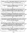
- Embodiments of the present invention provide a method and device for establishing a multi-protocol label switching traffic engineering tunnel, which are used for establishing the MPLS TE tunnel, by using a Mesh Group solution, between PEs that need to establish the MPLS TE tunnel, and ensures that an unnecessary MPLS TE tunnel is not established, and overcomes a limitation in establishing the MPLS TE tunnel by using the Mesh Group solution.
- An embodiment of the present invention provides a method for establishing a multi-protocol label switching traffic engineering MPLS TE tunnel, including:
- An embodiment of the present invention provides a device for establishing a multi-protocol label switching traffic engineering MPLS TE tunnel, including:
- each PE in the network releases a Mesh Group to which it belong through the IGP notification message, and releases its role information in the network service at the same time, and each PE determines whether to establish the MPLS TE tunnel with another PE belonging to the same Mesh Group with it according to its role information and the role information of the another PE belonging to the same Mesh Group with it, which does not establish the MPLS TE tunnel according to only a condition about whether they belong to the same Mesh Group as in the prior art, avoids establishing the unnecessary MPLS TE tunnel, and overcomes the limitation in establishing the MPLS TE tunnel by using the Mesh Group solution.
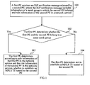
- FIG. 1 is a flow chart of a method for determining to establish an MPLS TE tunnel according to an embodiment of the present invention. As shown in FIG 1 , the method of this embodiment includes:
- Embodiments of the present invention are applicable to various networks supporting an MPLS VPN.
- a network in this embodiment may be an IP RAN in a 3G network architecture defined by 3GPP in a WCDMA R4 standard, but is not limited here.
- the network in this embodiment may further be the core network.
- role information of the first PE or the role information of the second PE in the network service is obtained by division according to an application scenario of the network service. That is to say, a role of each PE in the MPLS VPN network is divided according to the application scenario of the network service.
- the application scenario of the network service includes a hub-spoke (Hub-Spoke) scenario, a P2MP MPLS scenario, a unidirectional MPLS scenario, an inter-domain MPLS TE scenario and so on.
- the Hub-Spoke scenario is particularly applicable to the IP RAN network implemented based on an MPLS technology, but is not limited here.
- the role information of the PE includes a Hub node and a Spoke node, and it only needs to establish an MPLS TE tunnel from a Hub node to a Spoke node or from a Spoke node to a Hub node.
- the role information of the first PE in the network service may be the Hub node or the Spoke node
- the role information of the second PE in the network service may also be the Hub node or the Spoke node.
- the P2MP MPLS scenario refers to a scenario where a PE needs to establish the MPLS TE tunnel with multiple PEs.
- the role information of the PE includes a root node and a leaf node; and the root node needs to establish one P2MP MPLS TE tunnel with multiple leaf nodes.
- the role information of the first PE in the network service may be a root node or a leaf node, and the role information of the second PE in the network service may also be the root node or the leaf node.
- the unidirectional MPLS scenario refers to a scenario where the MPLS TE tunnel can only be established from a PE to another PE, and the MPLS TE tunnel cannot be established in a reverse direction.
- the role information of the PE includes an ingress node and an egress node; and the MPLS TE tunnel can only be established in a direction from the ingress node to the egress node.
- the role information of the first PE in the network service may be the ingress node or the egress node
- the role information of the second PE in the network service may also be the ingress node or the egress node.
- the inter-domain MPLS TE scenario refers to that network division needs to be performed by using an IGP multi-process or multi-area technology, that is, each PE belongs to a different IGP process or area.
- the role information of the PE may be an inter-domain border node (Border) in addition to the Hub node or the Spoke node, that is, the border node is located on two IGP processes or areas.
- the inter-domain MPLS TE scenario may further be combined with the P2MP MPLS scenario, the unidirectional MPLS scenario and so on, and at this time the role information of the PE may further include the inter-domain border node in addition to including the root node and the leaf node, or in addition to including the ingress node and the egress node.
- the inter-domain border node may further be a P device in addition to the PE.
- the MPLS TE tunnel establishment is described by taking a PE (namely, the first PE) in the network as an example.
- a procedure of the MPLS TE tunnel establishment of the PE is the same as that of the first PE, and therefore is not repeatedly described.
- the second PE refers to another PE in the network except the first PE. In different application scenarios of the network service, the number of second PEs may be different.
- each PE in the network belongs to a Mesh Group, and releases information of the Mesh Group to which it belongs through an IGP notification message.
- each PE when releasing the information of the Mesh Group to which it belongs, each PE further releases its role information in the network service at the same time.
- each PE in the network further receives an IGP notification message released by another PE, so as to obtain information of a Mesh Group to which the another PE belongs and role information of the another PE in the network service.
- the first PE further receives the IGP notification message sent by the second PE in the network, in addition to releasing information of a Mesh Group to which the first PE belongs and the role information of the first PE in the network service in the network through the IGP notification message.
- the second PE also receives an IGP notification message that is released by the first PE and includes the information of the Mesh Group to which the first PE belongs and the role information of the first PE in the network service, and after determining that the first PE and the second PE belong to the same Mesh Group according to the information of the Mesh Group to which the first PE belongs and the information of the Mesh Group to which the second PE belongs, determines, according to the role information of the first PE in the network service and the role information of the second PE in the network service, whether to establish the MPLS TE tunnel to the first PE.
- the information of the Mesh Group to which the first PE belongs and the role information of the PE in the network service may be configured for the first PE according to the application scenario of the network service.
- the information of the Mesh Group to which the another PE belongs and the role information of the another PE in the network service may also be configured for the another PE according to the application scenario of the network service.
- Step 102 The first PE determines, according to the information of the Mesh Group to which the first PE belongs and the information of the Mesh Group to which the second PE belongs, whether the first PE and the second PE belong to the same Mesh Group; if a judgment result is yes, that is, the first PE determines that the first PE and the second PE belong to the same Mesh Group, execute step 103; and optionally, if a judgment result is no, that is, the first PE determines that the first PE and the second PE do not belong to the same Mesh Group, execute step 104.
- the first PE parses the IGP notification message of the second PE, so as to obtain the information of the Mesh Group to which the second PE belongs and the role information of the second PE in the network service. Next, the first PE determines according to the information of the Mesh Groups to which the first PE and the second PE belong, whether the first PE and the second PE belong to the same Mesh Group.
- the first PE may judge whether the information of the Mesh Group to which the first PE belongs is the same as the information of the Mesh Group to which the second PE belongs; if a judgment result is that it is the same, the first PE determines that the first PE and the second PE belong the same Mesh Group; and otherwise, the first PE determines the first PE and the second PE belong to different Mesh Groups.
- the information of the Mesh Group may be any information that may uniquely indicate a Mesh Group such as a number, a name, and so on, of the Mesh Group.
- the IGP notification message released by the second PE may further include information about whether the Mesh Group to which the second PE belongs is a shared Mesh Group.
- That the first PE determines, according to the information of the Mesh Group to which the first PE belongs and the information of the Mesh Group to which the second PE belongs, whether the first PE and the second PE belong to the same Mesh Group includes:
- Step 103 The first PE determines, according to the role information of the first PE in the network service and the role information of the second PE in the network service, whether to establish the MPLS TE tunnel to the second PE.
- the first PE after judging that the first PE and the second PE belong to the same Mesh Group, the first PE does not directly determine that the MPLS TE tunnel needs to be established with the second PE as in the prior art, but further determines, according to the role information of the first PE and the role information of the second PE, whether the first PE needs to establish the MPLS TE tunnel to the second PE, so as to avoid establishing an unnecessary MPLS TE tunnel.
- Role information of a CSG in the IP RAN network may be seen as a Spoke node in the Hue-Spoke scenario, while role information of an RSG may be seen as a Hub node. If both roles of the first PE and the second PE are Hub nodes, or both roles of the first PE and the second PE are Spoke nodes, the MPLS TE tunnel does not need to be established between the first PE and the second PE, therefore, the first PE determines not to establish the MPLS TE tunnel to the second PE; and in another case, the first PE determines to establish the MPLS TE tunnel to the second PE.
- the first PE determines to establish the MPLS TE tunnel to the second PE; and after determining that the role information of the first PE is the same as the role information of the second PE, the first PE determines not to establish the MPLS TE tunnel to the second PE, that is, the MPLS TE tunnel is not established between a CSG and another CSG, or between an RSG and another RSG, and the MPLS TE tunnel is only established between a CSG and an RSG
- the P2MP MPLS scenario takes the P2MP MPLS scenario as an example.
- the first PE determines that the role information of the first PE in the network service is a leaf node, or determines that the role information of both the first PE and the second PE in the network service is a root node
- the P2MP MPLS TE tunnel does not need to be established between the first PE and the second PE, therefore, the first PE determines not to establish the P2MP MPLS TE tunnel to the second PE; and in another case, that is, after the first PE determines that the role information of the first PE in the network service is a root node, and the role information of the second PE in the network service is a leaf node, the first PE determines to establish the MPLS TE tunnel to the second PE.
- the first PE determines to establish the MPLS TE tunnel to the second PE; and after determining that the role information of the first PE in the network service is an egress node, or determining that the role information of both the first PE and the second PE in the network service is an ingress node, the first PE determines not to establish the MPLS TE tunnel to the second PE.
- Step 104 The first PE determines not to establish the MPLS TE tunnel to the second PE.
- the first PE judges that the first PE and the second PE do not belong to the same Mesh Group (that is, belong to different Mesh Groups)
- the MPLS TE tunnel cannot be established between the first PE and the second PE, therefore, the first PE determines not to establish the MPLS TE tunnel to the second PE.
- each PE in the network when releasing the information of the Mesh Group to which it belongs, each PE in the network releases its role information in the network service at the same time, each PE determines, according to the information of the Mesh Groups to which it and another PE belong and the role information of it and the another PE in the network service, whether to establish the MPLS TE tunnel to the another PE, which ensures that the MPLS TE tunnel is established between the PEs needing to establish the MPLS TE tunnel, and the MPLS TE tunnel is not established between the PEs that do not need to establish the MPLS TE tunnel, overcomes a limitation in establishing the MPLS TE tunnel by using a Mesh Group solution, and saves a resource consumed due to establishing the unnecessary MPLS TE tunnel.
- FIG 2 is a flow chart of a method for determining to establish an MPLS TE tunnel according to another embodiment of the present invention. This embodiment is implemented based on the embodiment shown in FIG 1 , and as shown in FIG. 2 , the method in this embodiment, before step 101, includes:
- the step 100 is used for pre-configuring the Mesh Group to which the first PE belongs and the role information of each PE in the network service.
- the configuration operation may be manually executed, and may also be that the first PE automatically configures, under control of a management device, the Mesh Group to which the first PE belongs and a role of the first PE in the network service.
- information of a Mesh Group to which each PE belongs and its role information in the network service also need to be pre-configured.
- the Mesh Group to which each PE belongs and the role information of each PE in the network service may be configured according to a service category. For example, bind an L3VPN service with a Mesh Group, that is, all PEs supporting the L3VPN service belong to a same Mesh Group, and configure role information of each PE supporting the L3VPN service when each PE supports the L3VPN service; and bind an L2VPN service with another Mesh Group, that is, all PEs supporting the L2VPN service belong to a same Mesh Group, and configure role information of each PE supporting the L2VPN service when each PE supports the L2VPN service.
- step 101 Take the several related application scenarios in step 101 as examples: If the application scenario of the network is a hub-Spoke scenario, configure the role information of the first PE as a Hub node or a Spoke node; and configure the role information of the second PE as a Hub node or a Spoke node.
- the application scenario of the network is a hub-Spoke scenario
- configure the role information of the first PE as a Hub node or a Spoke node
- the role information of the second PE configure the role information of the second PE as a Hub node or a Spoke node.
- an IP RAN network it is needed to configure role information of a CSG as a Spoke node, and configure role information of an RSG as a Hub node.
- the first PE may be the CSG or RSG, and the second PE may also be the CSG or RSG
- the application scenario of the network service is a P2MP MPLS scenario, configure the role information of the first PE as a root node or leaf node; and configure role information of the second PE as a root node or leaf node.
- the application scenario of the network service is a unidirectional MPLS scenario, configure the role information of the first PE as an ingress node or egress node; and configure role information of the second PE as an ingress node or egress node.
- role information of a device across multiple domains may be further configured as a border node.
- the inter-domain device may be a PE, and may also be a P device.
- an attribute used by each PE for establishing the MPLS TE tunnel may be further configured.
- the attribute includes bandwidth information, an explicit path, an affinity attribute, fast rerouting, and so on.
- a preferable implementation manner for configuring the attribute used by the PE for establishing the MPLS TE tunnel is: to configure an MPLS TE tunnel template used by the PE, where the template defines the attribute used by the PE for establishing the MPLS TE tunnel.
- a PE after a Mesh Group to which the PE belongs is configured, it is further needed to configure information such as an attribute used by a certain Mesh Group on the PE for establishing the MPLS TE tunnel, a policy of establishing the MPLS TE tunnel by using the configured attribute, and so on.
- the same PE may belong to different Mesh Groups at the same time. Different Mesh Groups may establish the MPLS TE tunnel by using different attributes.
- the policy of establishing the MPLS TE tunnel by using the configured attribute may be a shared manner or an exclusive manner.
- the shared manner indicates that when the MPLS TE tunnel is established by using the configured attribute, it is discovered that a corresponding MPLS TE tunnel already exists in the Mesh Group, so that the MPLS TE tunnel does not need to be established, and the existing MPLS TE tunnel is directly used.
- the exclusive manner indicates that when the MPLS TE tunnel is established by using the configured attribute, the existing MPLS TE tunnel is not considered, and an independent MPLS TE tunnel needs to be established for a service in the Mesh Group.
- the Mesh Group to which each PE belongs and the role information of each PE in the network service are pre-configured in the network, which provides a condition for each PE to release the information of the Mesh Group to which each PE belongs and the role information of each PE in the network service, and determine whether to establish the MPLS TE tunnel to another PE according to the information of the Mesh Group to which other PEs belong and the role information of other PEs in the network service.
- an execution manner of the configuration operation is not limited in this embodiment, which may be a manual configuration and may also be an automatic configuration of each PE, having a feature of flexible implementation.
- FIG. 3 is a flow chart of a method for determining to establish an MPLS TE tunnel according to still another embodiment of the present invention. This embodiment is implemented based on the embodiment shown in FIG 2 , and as shown in FIG. 3 , the method in this embodiment, after step 103, includes:
- the first PE and the second PE belong to a same IGP process or area, that is, in each application scenario that is not inter-domain, after determining, according to the role information of the first PE in the network service and the role information of the second PE in the network service, that the MPLS TE tunnel needs to be established to the second PE, the first PE uses an attribute corresponding to the Mesh Group and a shared/exclusive tunnel policy, and triggers a procedure of directly establishing the MPLS TE tunnel with the second PE, which does not have to pass through an inter-domain border node.
- the first PE and the second PE belong to different IGP processes or areas, that is, in an inter-domain MPLS TE scenario, after the first PE determines, according to the role information of the first PE in the network service and the role information of the second PE in the network service, that the MPLS TE tunnel needs to be established to the second PE, the first PE selects, from the Mesh Group to which the first PE belongs, a device whose role information is a border node, establishes a path to the selected device whose role information is the border node, and triggers that the selected device whose role information is the border node establishes a path to the second PE, so as to complete establishing the MPLS TE tunnel to the second PE.
- the path established from the first PE to the device whose role information is the border node and the path established from the device whose role information is the border node to the second PE form the MPLS TE tunnel from the first PE to the second PE.
- Both a procedure that the first PE establishes the path to the device whose role information is the border node and a procedure that the device whose role information is the border node establishes the path to the second PE have a same manner with a procedure that the first PE directly initiates the MPLS TE tunnel establishment to the second PE.
- the first PE When establishing the path to the device whose role information is the border node, the first PE notifies the device whose role information is the border node that the device whose role information is the border node needs to establish the path to the second PE and notifies the device whose role information is the border node of the role information of the second PE at the same time.
- role information of the border node may include a master border node and a backup border node. That is to say, in the inter-domain MPLS TE scenario, the role information of the first PE or the second PE or another PE or a P device may further be a master border node or a backup border node.
- the first PE selects a device whose role information is a border node from the Mesh Group to which the first PE belongs, establishes a path to the selected device whose role information is the border node, and triggers that the selected device whose role information is the border node establishes a path to the second PE, so as to complete establishing the MPLS TE tunnel to the second PE includes:
- the first PE selects a device whose role information is a backup border node from the Mesh Group to which the first PE belongs, establishes a path to the selected device whose role information is the backup border node, and triggers that the selected device whose role information is the backup border node establishes a path to the second PE, so as to complete establishing a backup MPLS TE tunnel to the second PE.
- the first PE may pre-bind the Mesh Group for an L3VPN or L2VPN service of the first PE, and bears the L3VPN or L2VPN service belonging to the Mesh Group by using an MPLS TE tunnel corresponding to the Mesh Group.
- the first PE may also not pre-bind the Mesh Group for the L3VPN or L2VPN service of the first PE, but binds the L3VPN or L2VPN service with the Mesh Group when starting the L3VPN or L2VPN service, and bears the L3VPN or L2VPN service belonging to the Mesh Group by using an MPLS TE tunnel corresponding to the bound Mesh Group.
- each PE after each PE determines to establish the MPLS TE tunnel to another PE according to role information of each PE in the network service and role information of the another PE belonging to the same Mesh Group in the network service, each PE directly initiates the MPLS TE tunnel establishment to the another PE, which lays a foundation for starting the L3VPN or L2VPN service based on the established MPLS TE tunnel.
- the first PE further sends an IGP notification message to the second PE (namely, another PE in the network) in addition to receiving an IGP notification message of the second PE.
- the IGP notification message sent by first PE includes information of the Mesh Group to which the first PE belongs and the role information of the first PE in the network service.
- the second PE first may first determine, according to the information of the Mesh Group to which the first PE belongs and information of the Mesh Group to which the second PE belongs, whether the first PE and the second PE belong to the same Mesh Group; after determining that the first PE and the second PE belong to the same Mesh Group, the second PE further determines, according to the role information of the first PE in the network service and the role information of the second PE in the network service, whether to establish the MPLS TE tunnel to the first PE; and after determining that the first PE and the second PE do not belong to the same Mesh Group, the second PE determines not to establish the MPLS TE tunnel to the first PE.
- the second PE when the information of the Mesh Group to which the second PE belongs and/or the role information of the second PE in the network service changes, the second PE re-sends the IGP notification message. Accordingly, the first PE receives the IGP notification message re-sent by the second PE, and re-determines whether to establish the MPLS TE tunnel to the second PE. Similarly, when the information of the Mesh Group to which the first PE belongs and/or the role information of the first PE in the network service changes, the first PE re-sends the IGP notification message. Accordingly, the second PE receives the IGP notification message re-sent by the first PE, and re-determines whether to establish the MPLS TE tunnel to the first PE.
- a procedure of a method for establishing an MPLS TE tunnel provided in the present invention is described in detail in combination with several specific application scenarios in the following.
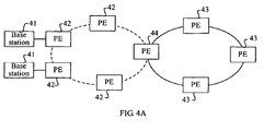
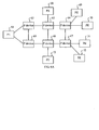
- FIG. 4A is a schematic structural diagram of a network in a Hub-Spoke scenario according to an embodiment of the present invention.
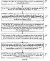
- FIG. 4B is a flow chart of a method for establishing an MPLS TE tunnel in the Hub-Spoke scenario according to the embodiment of the present invention.
- a Hub-Spoke service scenario in an IP RAN network is taken as an example, and the IP RAN network shown in FIG. 4A includes: base stations 41, PEs 42 on an access ring, PEs 43 on an aggregation ring, and a P device 44 on both the access ring and the aggregation ring.
- the ring shown in a dotted line is the access ring
- the ring shown in a solid line is the aggregation line.
- Each PE 42 on the access ring is connected to a base station 41, for convenience of illustration, FIG. 4A shows only two base stations 41 connected to the PEs 42, and another base station 41 connected to the PEs 42 are not shown.
- a PE 42 on the access ring is a CSG
- a PE 43 on the aggregation ring is an RSG.
- RSG is similar to a hub (Hub)
- a connection between the CSG and the RSG is similar to a spoke (Spoke)
- the CSG is connected to the Hub through the Spoke
- CSGs do not need to connect to each other through the Spoke.
- an existing Mesh Group mechanism is extended as follows: A Mesh Group node is defined with two roles, one is a Hub node, and the other is a Spoke node.
- a role of the CSG is the Spoke node
- a role of the RSG is the Hub node.
- the method in this embodiment includes:
- the first PE may be a PE 42 or a PE 43
- a second PE may also be a PE 42 or a PE 43.
- the description is made by taking that the first PE is a certain PE 42, and the second PE is a certain PE 43 as an example.
- a role of the PE 42 is configured as a Spoke node
- a role of the PE 43 is configured as a Hub node.
- Mesh Groups to which each PE 42 and PE 43 belong are configured according to a service category, for example, an L3VPN service is bound with a Mesh Group, that is, each PE 42 and PE 43 supporting the L3VPN service are configured into a same Mesh Group.
- An L2VPN service is bound with another Mesh Group, that is, each PE 42 and PE 43 supporting the L2VPN service are configured into the same Mesh Group.
- step 401 is an optional step in this embodiment.
- the first PE may be pre-configured with the Mesh Group to which the first PE belongs and the role information of the first PE in the network service.
- Step 402 In the IP RAN network, configure, for the first PE, an attribute used by the first PE for establishing an MPLS TE tunnel.
- an MPLS TE tunnel template may be used to define the attribute used for establishing the MPLS TE tunnel, and an MPLS TE tunnel template used by each first PE is configured, so as to achieve an objective of configuring the attribute used by the first PE for establishing the MPLS TE tunnel.
- attributes used by other PEs 42 or PEs 43 for establishing the MPLS TE tunnel may also be configured.
- step 402 is an optional step in this embodiment.
- Step 403 In IP RAN network, configure, for the first PE, an attribute used by each Mesh Group on the first PE for establishing the MPLS TE tunnel, and a policy of establishing the MPLS TE tunnel by using the configured attribute.
- the first PE may be configured with multiple different Mesh Groups.
- other PEs 42 or PEs 43 may also be configured with multiple different Mesh Groups.
- Different Mesh Groups may establish the MPLS TE tunnel by using different attributes.
- the policy of establishing the MPLS TE tunnel by using the configured attribute may be a shared manner or an exclusive manner. Reference is made to the description of the embodiment shown in FIG 2 for description of the shared manner and the exclusive manner.
- step 403 is an optional step in this embodiment.
- Step 404 After the first PE is configured with the Mesh Group to which the first PE belongs and the role information of the first PE in the network service, the first PE automatically releases an IGP notification message, and receives IGP notification messages released by other PEs 42 and PEs 43 in the network.
- the first PE releases the IGP notification message to other PEs 42 and all the PEs 43, and receives the IGP notification messages released by the other PEs 42 and all the PEs 43.
- the second PE also releases an IGP notification message to other PEs 43 and all the PEs 42, and receives the IGP notification messages released by the other PEs 43 and all the PEs 42.
- a Mesh Group to which a PE belongs may be indicated by using a Mesh Group number, and role information of the PE in the network service may be indicated by using a corresponding role bit, which is not limited here.
- Step 405 After learning the IGP notification messages of other PEs 42 and PEs 43, the first PE in the IP RAN network determines to establish the MPLS TE tunnel to the second PE belonging to the same Mesh Group.
- the first PE identifies a Mesh Group to which a PE sending an IGP notification message belongs according to a Mesh Group number in the received IGP notification message, and identifies, according to a bit of a Spoke role and a bit of a Hub role in the IGP notification message, a role of the PE sending the IGP notification message.
- the first PE determines, according to the Mesh Group to which the first PE belongs and the Mesh Groups to which other PEs 42 and PEs 43 belong, a PE 42 and PE 43 belonging to the same Mesh Group with the first PE; and then determines, according to the role information of the first PE in the network service and role information of the PE 42 and PE 43 belonging to the same Mesh Group with the first PE in the network service, that the MPLS TE tunnel needs to be established with the PE 43 in the same Mesh Group, and the MPLS TE tunnel does not needs to be established with the PE 42 in the same Mesh Group. That is, the Spoke node determines to establish the MPLS TE tunnel to the Hub node in the same Mesh Group.
- the PE 43 determines to establish the MPLS TE tunnel to the second PE.
- Other PEs 42 also adopt a manner the same as that of the first PE to determine whether to establish an MPLS TE tunnel to a certain PE 43.
- each PE 43 identifies a Mesh Group to which a PE sending an IGP notification message belongs according to a Mesh Group number in the received IGP notification, and identifies, according to a bit of a Spoke role and a bit of a Hub role in the IGP notification message, a role of the PE sending the IGP notification message.
- Each PE 43 identifies a PE 42 and PE 43 belonging to a same Mesh Group with it according to the Mesh Group to which it belongs and Mesh Groups to which other PEs 43 and all the PEs 42 belong; and then determines, according to the role information of it in the network service and the role information of the PE 42 and PE 43 belonging to the same Mesh Group with it in the network service, that the MPLS TE tunnel needs to be established with the PE 42 in the same Mesh Group. That is, the Hub node determines to establish the MPLS TE tunnel to the Spoke node in the same Mesh Group.
- the following content may be further included.
- Step 406 After determining to establish the MPLS TE tunnel with the second PE in the same Mesh Group, the first PE uses the attribute corresponding to the Mesh Group and the shared/exclusive tunnel policy to trigger establishment of the MPLS TE tunnel to the second PE.
- the first PE uses an RSVP-TE protocol to establish the MPLS TE tunnel from the first PE to the second PE in the same Mesh Group.
- PEs 42 or PEs 43 also use the RSVP-TE protocol to establish MPLS TE tunnels from them to PEs 43 or PEs 42 in the same Mesh Group.
- Step 407 The first PE uses the MPLS TE tunnel corresponding to the Mesh Group bound with the L3VPN or L2VPN service of the first PE to bear the L3VPN or L2VPN service.
- the MPLS TE tunnel corresponding to the Mesh Group is used to bear the L3VPN or L2VPN service belonging to the Mesh Group.
- the first PE does not pre-bind a specific Mesh Group for the L3VPN or L2VPN service of the first PE, when the L3VPN or L2VPN service is started, a Mesh Group is bound for the service of the first PE, and an MPLS TE tunnel corresponding to the Mesh Group is used to bear the corresponding service.
- the manner of using the MPLS TE tunnel to bear the corresponding service is the same as that of the first PE.
- each PE determines whether to establish the MPLS TE tunnel between each other according to both the belonged Mesh Group and the role information in the network service, which not only may ensure that the MPLS TE tunnel between a CSG and an RSG in the network is successfully established, but also may avoid establishing an MPLS TE tunnel between a CSG and another CSG or between an RSG and another RSG, overcomes a limitation in establishing the MPLS TE tunnel by using a Mesh Group solution, and saves a resource consumed due to establishing the MPLS TE tunnel between the CSG and the another CSG or between the RSG and the another RSG
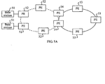
- FIG. 5A is a schematic structural diagram of a network in an inter-domain MPLS TE scenario according to another embodiment of the present invention.
- FIG 5B is a flow chart of a method for establishing an MPLS TE tunnel in the inter-domain MPLS TE scenario according to the another embodiment of the present invention.
- an inter-domain MPLS TE service scenario in an IP RAN network is taken as an example, and the IP RAN network shown in FIG 5A includes: base stations 51, PEs 52 on an access ring, PEs 53 on an aggregation ring, and PEs 54 on both the access ring and the aggregation ring.
- the ring shown in a dotted line is the access ring, where the access ring belongs to a first IGP process or area; and the ring shown in a solid line is the aggregation ring, where the aggregation ring belongs to a second IGP process or area.
- the PEs 54 are located in the two areas.
- a PE 52 on the access ring is a CSG
- a PE 53 on the aggregation ring is an RSG.
- an existing Mesh Group mechanism is extended as follows: A Mesh Group node is defined with three roles, one is a Hub node, one is a Spoke node, and one is a border node.
- a role of each PE 52 is the Spoke node
- a role of each PE 53 is the Hub node
- a role of a PE 54 is the border node.
- the method in this embodiment includes:
- network division is performed on the IP RAN network shown in FIG 5A by using an IGP multi-process or multi-area technology, that is, PEs on the access ring and the aggregation ring each belong to different IGP processes or areas, which facilitates control of the number of nodes and links in the network.
- IGP multi-process or multi-area technology that is, PEs on the access ring and the aggregation ring each belong to different IGP processes or areas, which facilitates control of the number of nodes and links in the network.
- MPLS TE link information is released only in a current area or process, a PE 52 or PE 53 in the IGP process or area may lack complete MPLS TE link information, so that a path to a PE 53 or PE 52 cannot be directly computed, and this is the inter-domain MPLS TE scenario.
- the border node belongs to multiple IGP processes or areas at the same time, and has more complete MPLS TE link information, so an MPLS TE tunnel may be established between PEs through the border node in the inter-domain MPLS TE scenario.
- the PE 54 belongs to both the first IGP process and the second IGP process or area, and the role of the PE 54 is the border node.
- a role of a PE 52 is a Spoke node
- a role of a PE 53 is a Hub node
- the role of the PE 54 is the border node.
- the first PE may be a PE 52 or PE 53
- a second PE may also be a PE 52 or PE 53.
- the description is made by taking that the first PE is a PE 52, and the second PE is a PE 53 as an example.
- the role of the PE 52 is configured as the Spoke node; the role of the PE 53 is configured as the Hub node; and the role of the PE 54 is configured as the border node.
- each PE 52, PE 53, and PE 54 belong are configured according to a service category, for example, an L3VPN service is bound with a Mesh Group, that is, each PE 52, PE 53, and PE 54 supporting the L3VPN service are configured into a same Mesh Group.
- An L2VPN service is bound with another Mesh Group, that is, each PE 52, PE 53, and PE 54 supporting the L2VPN service are configured into a same Mesh Group.
- step 501 is an optional step in this embodiment.
- the first PE may be pre-configured with the Mesh Group to which the first PE belongs and the role information of the first PE in the network service.
- Step 502 Configure, for the first PE, an attribute used by the first PE for establishing an MPLS TE tunnel.
- an MPLS TE tunnel template may be used to define the attribute used for establishing the MPLS TE tunnel, and an MPLS TE tunnel template used by each first PE is configured, so as to achieve an objective of configuring the attribute used by the first PE for establishing the MPLS TE tunnel.
- attributes used by other PE 52, PE 53, and PE 54 for establishing the MPLS TE tunnel may also be configured.
- step 502 is an optional step in this embodiment.
- Step 503 Configure, for the first PE, an attribute used by each Mesh Group on the first PE for establishing the MPLS TE tunnel, and a policy of establishing the MPLS TE tunnel by using the configured attribute.
- the first PE may be configured with multiple different Mesh Groups.
- other PE 52, PE 53, and PE 54 may also be configured with multiple different Mesh Groups.
- Different Mesh Groups may establish the MPLS TE tunnel by using different attributes.
- the policy of establishing the MPLS TE tunnel by using the configured attribute may be a shared manner or an exclusive manner. Reference is made to the description of the embodiment shown in FIG 2 for description of the shared manner and the exclusive manner.
- step 503 is an optional step in this embodiment.
- Step 504 After the first PE is configured with the Mesh Group to which the first PE belongs and the role information of the first PE in the network service, the first PE automatically releases an IGP notification message, and receives IGP notification messages released by other PEs (for example, a PE 52, PE 53, and PE 54).
- the first PE automatically releases an IGP notification message, and receives IGP notification messages released by other PEs (for example, a PE 52, PE 53, and PE 54).
- the first PE releases the IGP notification message to other PEs 52, all the PEs 53, and all the PEs 54, and receives the IGP notification messages released by the other PEs 52, all the PEs 53, and all the PEs 54.
- each 53 releases an IGP notification message to other PEs 53, all the PEs 52, and all the PEs 54, and receives the IGP notification messages released by other PE 53, all the PEs 52, and all the PEs 54.
- each PE 54 releases an IGP notification message to another PE 54, all the PEs 52, and all the PEs 53, and receives the IGP notification messages released by the another PE 54, all the PEs 52, and all the PEs 53.
- a Mesh Group to which each PE belongs may also be indicated by using a Mesh Group number
- role information of each PE in the network service may be indicated by using a bit of each role, which is not limited here.
- Step 505 The first PE determines to establish the MPLS TE tunnel with the second PE that belongs to the same Mesh Group and whose role is a Hub node according to the IGP notification message learned from other PEs (a PE 52, PE 53, and PE 54).
- the second PE is a PE 53.
- each PE 52 determines to establish the MPLS TE tunnel with a PE 53 that belongs to the same Mesh Group and whose role is the Hub node; and each PE 53 determines to establish the MPLS TE tunnel with a PE 52 that belongs to the same Mesh Group and whose role is the Spoke node.
- the following content may be further included.
- Step 506 After determining to establish the MPLS TE tunnel to the second PE, the first PE uses the attribute corresponding to the Mesh Group and the shared/exclusive tunnel policy to directly establish the MPLS TE tunnel to the second PE in the same Mesh Group.
- a PE 52 directly calculates the path from the PE 52 to a PE 53 in the same Mesh Group, if the calculation is successful, the PE 52 triggers establishment of the MPLS TE tunnel to the PE 53 in the same Mesh Group; and if the calculation fails, it means that the PE 52 cannot directly reach the PE 53 in the same Mesh Group.
- a PE 53 directly calculates the path from the PE 53 to a PE 52 in the same Mesh Group, if the calculation is successful, the PE 53 triggers establishment of the MPLS TE tunnel to the PE 52 in the same Mesh Group; and if the calculation fails, it means that the PE 53 cannot directly reach the PE 52 in the same Mesh Group.
- the PE 52 or PE 53 uses the identified PE whose role is the border node as a backup node for the MPLS TE tunnel path calculation. Therefore, when the calculation fails, the PE 52 or PE 53 may select a PE whose role is a border node from the same Mesh Group as an intermediate node from the PE 52 or PE 53 to a PE 53 or PE 52 in the same Mesh Group, and establish the MPLS TE tunnel to the PE 53 or PE 52 in the same Mesh Group based on the selected PE whose role is the border node, that is, execute step 507.
- the PE whose role is the border node is a PE 54. It is noted here that, the device whose role is the border node is not limited to a PE, and may also be a P device.
- the PE 52 or PE 53 uses an RSVP-TE protocol to directly establish the MPLS TE tunnel from it to the PE 53 or PE 52 in the same Mesh Group.
- Step 507 If the first PE fails to directly establish the MPLS TE tunnel to the second PE in the same Mesh Group, the first PE selects a PE 54 whose role is a border node from the same Mesh Group, and then establishes a path to the selected PE 54, and triggers that the selected PE 54 establishes a path to the second PE in the same Mesh Group, so as to complete establishing the MPLS TE tunnel to the second PE.
- the first PE also uses the RSVP-TE protocol to establish the path to the PE 54 whose role is the border node in the same Mesh Group, and the path is actually an MPLS TE tunnel from the first PE to the PE 54.
- the PE 54 whose role is the border node also uses the RSVP-TE protocol to establish the path to the second PE in the same Mesh Group, and the path is actually an MPLS TE tunnel from the PE 54 to the second PE.
- the two paths form a path from the first PE to the second PE, namely, the MPLS TE tunnel.
- the first PE When establishing the path to the PE 54, the first PE notifies the PE 54 that the PE 54 needs to establish the path to the second PE, and notifies the PE 54 of information of the second PE, so that the PE 54 may identify the second PE and establish the path to the second PE.
- the step ends; and otherwise, the selected PE 54 whose role is the border node returns information of no path to a head end (that is, to the first PE).
- the first PE re-selects another PE 54 whose role is the border node from the same Mesh Group according to the information of no path, where the information is fed back by the selected PE 54 whose role is the border node, and continues to try the path calculation and the MPLS TE tunnel establishment according to the operation of step 507.
- Step 508 The first PE uses the MPLS TE tunnel corresponding to the Mesh Group bound with the L3VPN or L2VPN service of the first PE to bear the L3 VPN or L2VPN service.
- step 407 for step 508, which is not repeatedly described here.
- an IGP notification message is re-sent, but also when a role information of a PE whose role is a border node in the network service and/or a Mesh Group to which the PE whose role is the border node belongs changes, the IGP notification message is re-sent.
- each PE in the network triggers deletion of an existing MPLS TE tunnel and establishes a new MPLS TE tunnel according to an updated Mesh Group and updated role information in the network service.
- an inter-domain node is further configured as a border node and release is performed through the IGP notification message, so that nodes in different areas may complete establishing the MPLS TE tunnel through the border node, which solves a problem of establishing the MPLS TE tunnel in the inter-domain scenario.
- role information of the PE may be configured as a master border node or a backup border node.
- the first PE may select a PE 54 whose role is a master border node, establish a path to the selected PE 54 whose role is the master border node, and trigger that the selected PE 54 whose role is the master border node establishes a master MPLS TE tunnel to the second PE in the same Mesh Group.
- the first PE may select a PE 54 whose role information is a backup border node, establish a path to the selected PE 54 whose role information is a backup border node, and trigger that the selected PE 54 whose role is the backup border node establishes a backup MPLS TE tunnel to the second PE in the same Mesh Group.
- the first PE selects both the PE 54 whose role is the master border node and the PE 54 whose role is the backup border node, and establishes the master MPLS TE tunnel and the backup MPLS TE tunnel to the second PE in the same Mesh Group at the same time.
- the role of the border node is further divided, which facilitates the inter-domain MPLS TE tunnel path calculation in a specific scenario.
- a PE 42 when a PE 42 serves as the first PE, a PE 43 belonging to a same Mesh Group with the PE 42 is the second PE; and when a PE 43 serves as the first PE, a PE 42 belonging to a same Mesh Group with the PE 43 is the second PE.
- a PE 52 when a PE 52 serves as the first PE, a PE 53 belonging to a same Mesh Group with the PE 52 is the second PE; and when a PE 53 serves as the first PE, a PE 52 belonging to the same Mesh Group with the PE 53 is the second PE.
- FIG. 6A is a schematic structural diagram of a network in a P2MP MPLS scenario according to an embodiment of the present invention.
- FIG 6B is a flow chart of a method for establishing an MPLS TE tunnel in the P2MP MPLS scenario according to the embodiment of the present invention.
- the network in the P2MP MPLS scenario (referred to as a P2MP MPLS network) includes: a PE 61, a P device 62, a P device 63, a P device 64, a P device 65, a P device 66, a P device 67, a PE 68, a PE 69, a PE 70, a PE 71, a PE 72, and a PE 73.
- the PE 61 is connected to the P device 62 and the P device 65, the P device 62, the P device 63, and the P device 64 are connected in sequence, the P device 65, the P device 66, and the P device 67 are connected in sequence, the P device 62 is connected to the P device 65, the P device 63 is connected to the P device 66, the P device 64 is connected to the P device 67, the PE 68 is connected to the P device 63, the PE 69 is connected to the P device 64, the PE 70 is connected to the P device 64, the PE 71 is connected to the P device 67, the PE 72 is connected to the P device 67, and the PE 73 is connected to the P device 66.
- the PE 61 needs to establish a P2MP MPLS TE tunnel with the PE 68, PE 69, PE 70, PE 71, PE 72, and PE 73 at the same time.
- the P2MP MPLS scenario may be a multicast service implemented based on an MPLS TE technology, which is not limited here.
- an auto-discovery mechanism of BGP is adopted to implement discovery of each PE in an MVPN.
- the BGP determines relationship between a root and a leaf between PEs in the MVPN by delivering information between PEs.
- the network does not support the BGP protocol, the discovery of the relationship between the root and the leaf between the PEs cannot be completed, and the BGP protocol is complicated, which increases difficulty of network management and maintenance.
- an existing IGP Mesh Group mechanism is extended as follows: A Mesh Group defines two roles for a node, one is a root (Root) node in the P2MP, and the other is a leaf (Leaf) node in the P2MP. When releasing Mesh Group information, an IGP releases role information of each PE in the P2MP MPLS network at the same time.
- the PE 61 is the root node, and the other PEs are leaf nodes.
- the method in this embodiment includes:
- the PE 61 is a first PE
- the PE 68, PE 69, PE 70, PE 71, PE 72, and PE 73 are all second PEs.
- the role information of the PE 61 is configured as a root node
- the role information of the PE 68-PE 73 is all configured as leaf nodes.
- Mesh Groups to which the PE 61 and the PE 68-PE 73 belong are configured according to a service category, for example, a multicast L3VPN service is bound with a Mesh Group, that is, each PE supporting the multicast L3VPN service is configured into a same Mesh Group.
- a multicast L2VPN service is bound with another Mesh Group, that is, each PE supporting the multicast L2VPN service is configured into a same Mesh Group.
- the PE 61 and the PE 68-PE 73 are configured in the same Mesh Group.
- step 601 is an optional step in this embodiment.
- Step 602 Configure, for the PE 61, an attribute used by the PE 61 for establishing an MPLS TE tunnel.
- attributes used by other PEs or P devices for establishing the MPLS TE tunnel may also be configured.
- step 602 is an optional step in this embodiment.
- Step 603 Configure, for the PE 61, an attribute used by each Mesh Group on the PE 61 for establishing the MPLS TE tunnel, and a policy of establishing the MPLS TE tunnel by using the configured attribute.
- the PE 61 and the PE 68-PE 73 may be configured with multiple different Mesh Groups. Different Mesh Groups may establish the MPLS TE tunnel by using different attributes.
- the policy of establishing the MPLS TE tunnel by using the configured attribute may be a shared manner or an exclusive manner. Reference is made to the description of the embodiment shown in FIG. 2 for description of the shared manner and the exclusive manner.
- Step 604 After the PE 61 is configured with the Mesh Group to which the PE 61 belongs and the role information of the PE 61 in the network service, the PE 61 automatically releases an IGP notification message, and receives IGP notification messages released by other PEs.
- the PE 61 releases the IGP notification message to the PE 68-the PE 73, and receives the IGP notification messages released by the PE 68-PE 73.
- the PE 68 releases an IGP notification message to the PE 61 and the PE 69 to the PE 73, and receives IGP notification messages released by the PE 61 and the PE 69 to the PE 73.
- a Mesh Group to which a PE belongs may be indicated by using a Mesh Group number, and role information of the PE in the network service may be indicated by using a corresponding role bit, which is not limited here.
- Step 605 After learning the IGP notification messages of other PEs, the PE 61 determines to establish a P2MP MPLS TE tunnel with the PE 68-PE 73 in the same Mesh Group.
- the P2MP MPLS TE tunnel in this embodiment is one MPLS TE tunnel from one root node to multiple leaf nodes, instead of multiple MPLS TE tunnels.
- Step 606 After determining to establish the P2MP MPLS TE tunnel to the PE 68-PE 73, the PE 61 uses the attribute corresponding to the Mesh Group and the shared/exclusive tunnel policy, and triggers establishment of the P2MP MPLS TE tunnel.
- the PE 61 uses an RSVP-TE protocol to establish the P2MP MPLS TE tunnel from the PE 61 to the PE 68-PE 73 in the same Mesh Group.
- Step 607 The PE 61 uses the P2MP MPLS TE tunnel corresponding to the Mesh Group bound with the multicast L3VPN or multicast L2VPN service of the PE 61 to bear the multicast L3VPN or multicast L2VPN service.
- the MPLS TE tunnel corresponding to the Mesh Group is used to bear the multicast L3VPN or multicast L2VPN service belonging to the Mesh Group.
- the PE 61 and the PE 68-PE 73 do not pre-bind the specific Mesh Group for the multicast L3VPN or multicast L2VPN service of the PE 61 and the PE 68-PE 73, when the multicast L3VPN or multicast L2VPN service is started, a Mesh Group is bound for the service of the PE 61 and the PE 68-PE 73, and an MPLS TE tunnel corresponding to the Mesh Group is used to bear the corresponding service.
- each PE for example, the PE 61 and the PE 68-PE 73
- the service of each PE belongs changes, or role information of each PE in the network service changes, re-releasing of an IGP notification message is triggered, and the PE 61 re-establishes a P2MP MPLS TE tunnel according to an updated Mesh Group and updated role information in the network service.
- the Mesh Group to which each PE belongs and the role information of each PE in the network service are pre-configured, and the belonged Mesh Group and the role information in the network service are released through the IGP notification message at the same time, so that the PE as the root node determines whether to establish the P2MP MPLS TE tunnel to other PEs according to both the Mesh Group to which each PE belongs and the role information of each PE in the network service, which implements successful establishment of the P2MP MPLS TE tunnel between the root node and multiple leaf nodes in a situation that a BGP protocol is not needed.
- FIG. 7 is a flow chart of a method for establishing an MPLS TE tunnel in a unidirectional MPLS scenario according to an embodiment of the present invention. This embodiment is implemented based on the network shown in FIG. 6A .
- the PE 61 can only establish an MPLS TE tunnel to any one PE in the PE 68-the PE 73, and the any one PE in the PE 68-PE 73 cannot establish the MPLS TE tunnel to the PE 61 in a reverse direction.
- an existing IGP Mesh Group mechanism is extended as follows: A Mesh Group defines two roles for a node, one is an ingress (Ingress) node, and the other is an egress (Egress) node. When releasing Mesh Group information, the IGP releases role information of each PE in the unidirectional MPLS network at the same time.
- This embodiment caters a service application where a unidirectional MPLS TE tunnel needs to be established, for example, in a case of no P2MP TE tunnel, a method of copying a multicast head end is adopted to support a multicast VPN, that is, an action of using a unidirectional P2P TE tunnel to simulate a P2MP TE; or an application where the unidirectional MPLS TE tunnel is used when only unidirectional traffic exists in some L3VPN scenarios.
- the method in this embodiment includes:
- the Mesh Groups to which other PEs or P devices belong and role information of other PEs or P devices in the network service also need to be configured.
- the role information of the PE 61 in the network service is configured as an ingress node
- role information of the PE 68-PE 73 in the network service is all configured as egress nodes.
- the Mesh Groups to which the PE 61 and the PE 68-PE 73 belong are configured according to a service category, for example, an L3VPN service is bound with a Mesh Group, that is, each PE supporting the L3VPN service is configured into a same Mesh Group.
- An L2VPN service is bound with another Mesh Group, that is, each PE supporting the L2VPN service is configured into a same Mesh Group.
- step 701 is an optional step in this embodiment.
- Step 702 Configure, for the PE 61, an attribute used by the PE 61 for establishing the MPLS TE tunnel.
- attributes used by other PEs or P devices for establishing the MPLS TE tunnel may also be configured.
- step 702 is an optional step in this embodiment.
- Step 703 Configure, for the PE 61, an attribute used by each Mesh Group on the PE 61 for establishing the MPLS TE tunnel, and a policy of establishing the MPLS TE tunnel by using the configured attribute.
- step 703 is an optional step in this embodiment.
- Step 704 After the PE 61 is configured with the Mesh Group to which the PE 61 belongs and the role information of the PE 61 in the network service, the PE 61 automatically releases an IGP notification message, and receives IGP notification messages released by other PEs.
- the PE 61 releases the IGP notification message to the PE 68-PE 73, and receives the IGP notification messages released by the PE 68 to the PE 73.
- the PE 68 releases an IGP notification message to the PE 61 and the PE 69-PE 73, and receives the IGP notification messages released by the PE 61 and the PE 69-PE 73.
- a Mesh Group to which a PE belongs may be indicated by using a Mesh Group number, and role information of the PE in the network service may be indicated by using a corresponding role bit, which is not limited here.
- Step 705 After learning the IGP notification messages of other PEs, the PE 61 determines to establish the MPLS TE tunnel with each of the PE 68-PE 73 in the same Mesh Group.
- the PE 61 learns that the PE 61 and the PE 68-PE 73 belongs to the same Mesh Group, and the role information of the PE 61 in the network service is the root node according to the learned IGP notification message, and the role information of the PE 68-PE 73 in the network service is all the leaf nodes, therefore, the PE 61 determines to establish the MPLS TE tunnel with each of the PE 68-PE 73.
- Step 706 After determining to establish the MPLS TE tunnel with each of the PE 68-PE 73, the PE 61 uses the attribute corresponding to the Mesh Group and the shared/exclusive tunnel policy, and triggers establishment of multiple MPLS TE tunnels to the PE 68-PE 73.
- the PE 61 uses an RSVP-TE protocol to establish an MPLS TE tunnel to each PE in the PE 68-PE 73.
- Step 707 The PE 61 uses the MPLS TE tunnel corresponding to the Mesh Group bound with the L3VPN or L2VPN service of the PE 61 to bear the L3VPN or L2VPN service.
- step 702 to step 707 is similar to the description of step 602 to step 607, and a difference lies in that, in the embodiment shown in FIG 6B , a P2MP MPLS TE tunnel is finally established between the PE 61 and the PE 68-PE 73; while in this embodiment, the PE 61 establishes a MPLS TE tunnel with each PE in the PE 68-PE 73, which is a combination of multiple unidirectional MPLS TE tunnels to multiple destination nodes.
- the Mesh Group to which each PE belongs and the role information of each PE in the network service are pre-configured, and the belonged Mesh Group and role are released through the IGP notification message, so that each PE determines whether to establish the MPLS TE tunnel between each other according to both the belonged Mesh Group and role, which implements establishment of the unidirectional MPLS TE tunnel between the nodes, and extends the application of using the Mesh Group to establish the MPLS TE tunnel.
- a PE needs to establish the MPLS TE tunnel with multiple PEs at the same time, and the multiple PEs each belongs to different Mesh Groups, the PE needs to be configured with multiple Mesh Groups.
- the PE on the aggregation ring needs to establish the MPLS TE tunnel with multiple PEs on the access ring, and the multiple PEs on the access ring each belongs to different Mesh Groups, the PE on the aggregation ring needs to be configured with multiple Mesh Groups, and the configuration number of the Mesh Groups increases with a needed number, which not only causes resource waste, but also increases a configuration workload.
- the existing IGP Mesh Group is extended as follows: a specific Mesh Group is defined as a shared Mesh Group, and is released through the IGP.
- a PE in the shared Mesh Group is considered as a common node of different Mesh Groups, PEs in different Mesh Groups consider the PE in the shared Mesh Group as a PE in their Mesh Groups, and establish a corresponding MPLS TE tunnel according to a requirement of a role.
- the solution is applicable to any one application scenario, for example, the Hub-Spoke scenario, the P2MP MPLS scenario, the unidirectional MPLS scenario, and the inter-domain MPLS TE scenario.
- Role information of a corresponding PE in the shared Mesh Group in the network service may be a Spoke node or a Hub node, a root node or a leaf node, an ingress node or an egress node, or the Spoke node or the Hub node or a border node.
- FIG. 8 is a flow chart of establishing an MPLS TE tunnel based on a configuration shared Mesh Group according to an embodiment of the present invention. As shown in FIG. 8 , the method in this embodiment includes:
- the Mesh Group to which the PE belongs is configured as a shared Mesh Group; and otherwise, the Mesh Group to which the first PE belongs is configured as a non-shared Mesh Group.
- PEs in the network also need to be configured with belonged Mesh Groups and role information in the network service, and it is also needed to configure whether their belonged Mesh Groups are shared Mesh Groups.
- a procedure of configuring whether the Mesh Groups to which the other PEs belong are shared Mesh Groups is the same as that of configuring whether the Mesh Group to which the first PE belongs is a shared Mesh Group.
- step 801 is an optional step in this embodiment.
- Step 802 Configure, for the first PE, an attribute used by the first PE for establishing the MPLS TE tunnel.
- PEs in the network also need to be configured with attributes used by the other PEs for establishing the MPLS TE tunnel.
- step 802 is an optional step in this embodiment.
- Step 803 Configure, for the first PE, an attribute used by each Mesh Group on the first PE for establishing the MPLS TE tunnel, and a policy of establishing the MPLS TE tunnel by using the configured attribute.
- PEs in the network also need to be configured with an attribute used by each Mesh Group on the other PEs for establishing the MPLS TE tunnel, and a policy of establishing the MPLS TE tunnel by using the configured attribute.
- step 803 is an optional step in this embodiment.
- Step 804 After the first PE is configured with the Mesh Group to which the first PE belongs and the role information of the first PE in the network service, the first PE automatically releases an IGP notification message, and receives IGP notification messages released by other PEs.
- both the first PE and other PEs automatically release IGP notification messages, and receive the IGP messages sent by other PEs.
- a Mesh Group to which a PE belongs may be indicated by using a Mesh Group number
- role information of the PE in the network service may be indicated by using a corresponding role bit
- Step 805 After learning the IGP notification messages of other PEs, the first PE identifies whether the Mesh Groups to which other PEs belongs are shared Mesh Groups according to the shared bits in the IGP notification messages, and determines whether other PEs belong to the same Mesh Group with the first PE according to an identification result.
- the first PE determines that the first PE and other PEs belong to the same Mesh Group.
- the first PE determines that the first PE and the other PEs belong to the same Mesh Group
- the first PE determines that the first PE and the other PEs do not belong to the same Mesh Group.
- Step 806 When the first PE identifies that the first PE and other PEs belong to the same Mesh Group, the first PE determines, according to the role information of the first PE in the network service and the role information of the other PEs belonging to the same Mesh Group in the network service, whether to establish the MPLS TE tunnel with the other PEs belonging to the same Mesh Group.
- step 806 specifically, there are different determination results in different application scenarios, and reference may be made to corresponding description in the foregoing embodiments shown in FIG 4A to FIG 7 for the determination results of the application scenarios.
- Step 807 After establishing the MPLS TE tunnel that needs to be established, the first PE uses the attribute corresponding to the Mesh Group and the shared/exclusive tunnel policy, and trigger establishment of the MPLS TE tunnel.
- Step 808 The first PE uses the MPLS TE tunnel corresponding to a Mesh Group bound with an L3VPN or L2VPN service of the first PE to bear the L3VPN or L2VPN service.
- the shared Mesh Group is configured, which may reduce the number of the configured Mesh Groups on the PEs and the corresponding roles, facilitate reduction of a configuration workload, and save a resource.
- the IGP notification message of the foregoing embodiments may be implemented by extending a message of notifying the Mesh Group information in the prior art, and may also be implemented by defining a new message.
- RFC 4972 defines a TLV of the IGP extension, namely, a TE Mesh Group TLV, then a procedure of implementing the IGP notification message by extending the message of notifying the Mesh Group information in the prior art is mainly a procedure of extending the TE Mesh Group TLV.
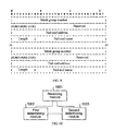
- FIG 9 shows a format of an IGP notification message in the ISIS protocol according to the embodiment of the present invention. As shown in FIG 9 , field information included in the IGP notification message in this embodiment is as shown in Table 1.
- Tail-end address (tail-end address) Indicate an identifier of the PE belonging to the Mesh Group indicated by the Mesh Group number
- Tail-end name (tail-end name) Indicate a name of the PE belonging to the Mesh Group indicated by the Mesh Group number, which usually is a character string
- Tail-end name length (name Length) Indicate the number of bits occupied by the tail-end name Shared bit (Shared mode bit, S) Indicate whether the Mesh Group indicated by the Mesh Group number is a shared Mesh Group, for example, a value of 0 indicates no, and a value of 1 indicates yes
- Hub role bit (Hub Node bit, H) Indicate whether a role of the PE is a Hub, for example, a value of 0 indicates no, and a value of 1 indicates yes
- Spoke role bit (Spoke Node
- the extending the Mesh Group TLV is mainly to: based on the existing information of the Mesh Group TLV, increase a bit to define whether the Mesh Group is shared and the role of the PE in the Mesh Group.
- a new type of Mesh Group TLV needs to be extended, so as to be distinguished from an existing Mesh Group TLV.
- the IGP distribution processing procedure of the extended Mesh Group TLV is consistent with a distribution processing procedure of the existing Mesh Group TLV defined by the RFC 4972, and is not changed.
- Compatibility processing between the extended Mesh Group TLV in this embodiment and the existing Mesh Group TLV is as follows: if a mesh-group-number and tail-end address of the existing Mesh Group TLV are consistent with those of the extended Mesh Group TLV in this embodiment, the PE needs to participate in establishing an MPLS TE tunnel connection in a full connection manner defined by the existing Mesh Group TLV, and further needs to participate in establishing an MPLS TE tunnel connection in an extension manner defined by the extended Mesh Group TLV. If in the extended Mesh Group, the Mesh Group is defined as a shared Mesh Group, the PE defined in the existing Mesh Group TLV, as a shared node, establishes a Full Mesh MPLS TE tunnel connection with a PE in another Mesh Group.
- the IGP notification message provided in this embodiment may only include information related to the application scenario.
- the IGP notification message may not include the root node bit, the leaf node bit, the ingress node bit, the egress node bit, and the like.
- the IGP notification message may not include the Hub node bit, the Spoke node bit, the border node bit, the ingress node bit, the egress node bit, and the like.
- FIG. 10 is a schematic structural diagram of a device for determining to establish an MPLS TE tunnel according to an embodiment of the present invention. As shown in FIG. 10 , the device in this embodiment includes: a receiving module 1001, a determining module 1002, and a second determining module 1003.
- the receiving module 1001 is configured to receive an IGP notification message released by a second device for determining to establish the MPLS TE tunnel in a network, where the IGP notification message includes information of a Mesh Group to which the second device for determining to establish the MPLS TE tunnel belongs and role information of the second device for determining to establish the MPLS TE tunnel in a network service, and the role information of the second device for determining to establish the MPLS TE tunnel in the network service is obtained by division according to an application scenario of the network service.
- the device for determining to establish the MPLS TE tunnel in this embodiment shown in FIG 10 may be referred to as a first device for determining to establish the MPLS TE tunnel.
- the receiving module 1001 is a receiving interface.
- the first determining module 1002 is configured to: according to information of a Mesh Group to which the device for determining to establish the MPLS TE tunnel in this embodiment belongs and the information of the Mesh Group to which the second device for determining to establish the MPLS TE tunnel belongs received by the receiving module 1001, determine whether the device for determining to establish the MPLS TE tunnel in this embodiment and the second device for determining to establish the MPLS TE tunnel belong to a same Mesh Group.
- the first determining module 1002 is connected to the receiving module 1001.
- the first determining module is a processor.
- the second determining module 1003 is configured to: after the first determining module 1002 determines that the device for determining to establish the MPLS TE tunnel in this embodiment and the second device for determining to establish the MPLS TE tunnel belong to the same Mesh Group, determine, according to the role information of the device for determining to establish the MPLS TE tunnel in this embodiment in the network service and the role information, received by the receiving module 1001, of the second device for determining to establish the MPLS TE tunnel in the network service, whether to establish the MPLS TE tunnel to the second device for determining to establish the MPLS TE tunnel.
- the second determining module 1003 is connected to the receiving module 1001 and the first determining module 1002.
- the second determining module is a processor.
- the first determining module and the second determining module may be the same processor. That is to say, a function of the first determining module and a function of the second determining module may be executed by different processors, and may also be executed by the same processor.
- the second device for determining to establish the MPLS TE tunnel refers to one or more of other devices for determining to establish an MPLS TE tunnel in the network except the device for determining to establish the MPLS TE tunnel in this embodiment.
- the device for determining to establish the MPLS TE tunnel in this embodiment may be a PE or P device in an MPLS VPN network.
- the application scenario of the network service in this embodiment may be a Hub-Spoke scenario, a P2MP MPLS scenario, a unidirectional MPLS scenario, an inter-domain MPLS TE scenario, and so on.
- the role information includes a Hub node and a Spoke node.
- the MPLS TE tunnel is only allowed to be established between the Hub node and the Spoke node, and the MPLS TE tunnel is not allowed not be established between Hub nodes or between Spoke nodes.
- the role information includes a root node and a leaf node.
- a root node establishes a P2MP MPLS TE tunnel with multiple leaf nodes.
- the unidirectional MPLS scenario refers to a scenario where the MPLS TE tunnel can only be established from a device for determining to establish an MPLS TE tunnel to another device for determining to establish an MPLS TE tunnel, but the MPLS TE tunnel cannot be established in a reverse direction.
- the role information of the PE includes an ingress node and an egress node; and the MPLS TE tunnel can only be established in a direction from the ingress node to the egress node.
- the inter-domain MPLS TE scenario refers to that an IGP multi-process or multi-area technology is used for network division, so that devices for determining to establish an MPLS TE tunnel that need to establish the MPLS TE tunnel locate in different IGP processes or areas.
- the role information further includes an inter-domain border node.
- the inter-domain MPLS TE scenario may be combined with the Hub-Spoke scenario, the P2MP MPLS scenario, or the unidirectional MPLS scenario, so a role in the inter-domain MPLS TE scenario, in addition to including the Hub node and Spoke node, or in addition to including the root node and leaf node, or in addition to including the ingress node and egress node, further includes the inter-domain border node (Border), that is, the border node is on two IGP processes or areas.
- Border inter-domain border node
- the functional modules of the device for determining to establish the MPLS TE tunnel provided in this embodiment may be used to execute the procedure of the method for establishing the MPLS TE tunnel shown in FIG. 1 , and reference is made to the description of the method embodiment for a specific working principle, which is not repeatedly described here.
- the device for determining to establish the MPLS TE tunnel in this embodiment releases its role information in the network service at the same time, and each device for determining to establish an MPLS TE tunnel determines, according to both information of Mesh Groups to which each device for determining to establish the MPLS TE tunnel and another device for determining to establish the MPLS TE tunnel belong and role information of each device for determining to establish the MPLS TE tunnel and the another device for determining to establish the MPLS TE tunnel in the network service, whether to establish the MPLS TE tunnel to the another device for determining to establish an MPLS TE tunnel, which ensures that the MPLS TE tunnel is established between the devices for determining to establish the MPLS TE tunnel that need to establish the MPLS TE tunnel, and the MPLS TE tunnel is not established between the devices for determining to establish the MPLS TE tunnel that do not need not to establish the MPLS TE tunnel, overcomes
- FIG. 11 is a schematic structural diagram of a device for determining to establish an MPLS TE tunnel according to another embodiment of the present invention. This embodiment is implemented based on the embodiment shown in FIG. 10 . In this embodiment, for different application scenarios of network services, the function of the second determining module 1003 is not completely the same.
- role information of the device for determining to establish the MPLS TE tunnel in this embodiment in the network service may be a Hub node or a Spoke node
- role information of a second device for determining to establish an MPLS TE tunnel in the network service may be a Hub node or a Spoke node
- the second determining module 1003 in this embodiment is specifically configured to: after determining that the role information of the device for determining to establish the MPLS TE tunnel in this embodiment in the network service is different from the role information of the second device for determining to establish the MPLS TE tunnel in the network service, determine to establish the MPLS TE tunnel to the second device for determining to establish the MPLS TE tunnel.
- the second determining module 1003 in this embodiment is further specifically configured to: after determining that the role information of the device for determining to establish the MPLS TE tunnel in this embodiment in the network service is the same as the role information of the second device for determining to establish the MPLS TE tunnel in the network service, determine not to establish the MPLS TE tunnel to the second device for determining to establish the MPLS TE tunnel.
- the role information of the device for determining to establish the MPLS TE tunnel in this embodiment in the network service may be a root node or a leaf node
- the role information of the second device for determining to establish the MPLS TE tunnel in the network service may be a root node or a leaf node.
- the second determining module 1003 in this embodiment is specifically configured to: after determining that the role information of the device for determining to establish the MPLS TE tunnel in this embodiment in the network service is a root node, and the role information of the second device for determining to establish the MPLS TE tunnel in the network service is a leaf node, determine to establish a P2MP MPLS TE tunnel to the second device for determining to establish the MPLS TE tunnel.
- the second determining module 1003 in this embodiment is further specifically configured to determine not to establish the P2MP MPLS TE tunnel to the second device for determining to establish the MPLS TE tunnel, after determining that the role of the device for determining to establish the MPLS TE tunnel in this embodiment is a leaf node, or after determining that the role information of both the device for determining to establish the MPLS TE tunnel in this embodiment and the second device for determining to establish the MPLS TE tunnel in the network service is a root node.
- the role information of the device for determining to establish the MPLS TE tunnel in this embodiment in the network service may be an ingress node or an egress node
- the role information of the second device for determining to establish the MPLS TE tunnel in the network service may be an ingress node or an egress node
- the second determining module 1003 in this embodiment is specifically configured to: after determining that the role information of the device for determining to establish the MPLS TE tunnel in this embodiment in the network service is an ingress node, and the role information of the second device for determining to establish the MPLS TE tunnel in the network service is an egress node, determine to establish the MPLS TE tunnel to the second device for determining to establish the MPLS TE tunnel.
- the second determining module 1003 in this embodiment is further specifically configured to: after determining that the role of the device for determining to establish the MPLS TE tunnel in this embodiment in the network service is an ingress node, or after determining that the role information of both the device for determining to establish the MPLS TE tunnel in this embodiment and the second device for determining to establish the MPLS TE tunnel in the network service is an ingress node, determine not to establish the MPLS TE tunnel to the second device for determining to establish the MPLS TE tunnel.
- the second determining module 1003 in this embodiment is further specifically configured to, after determining to establish the MPLS TE tunnel to the second device for determining to establish the MPLS TE tunnel, select a device whose role information is a border node from a Mesh Group to which the device for determining to establish the MPLS TE tunnel in this embodiment belongs, establish a path to the device whose role information is the border node, and trigger that the device whose role information is the border node establishes a path to the second device for determining to establish the MPLS TE tunnel, so as to complete establishing the MPLS TE tunnel to the second device for determining to establish the MPLS TE tunnel.
- a role of the border node may further be divided into a master border node and a backup border node.
- the second determining module 1003 is specifically configured to select a device whose role information is a master border node from the Mesh Group to which the device for determining to establish the MPLS TE tunnel in this embodiment belongs, establish a path to the selected device whose role information is the master border node, and trigger that the selected device whose role is the master border node establishes a path to the second device for determining to establish the MPLS TE tunnel, so as to complete establishing a master MPLS TE tunnel to the second device for determining to establish the MPLS TE tunnel.
- the second determining module 1003 is specifically configured to select a device whose role information is a backup border node from the Mesh Group to which the device for determining to establish the MPLS TE tunnel in this embodiment belongs, establish a path to the selected device whose role information is the backup border node, and trigger that the selected device whose role information is the backup border node establishes a path to the second device for determining to establish the MPLS TE tunnel, so as to complete establishing a backup MPLS TE tunnel to the second device for determining to establish the MPLS TE tunnel.
- the device whose role information is the border node in the network service may be a PE, and may also be a P device.
- the device for determining to establish the MPLS TE tunnel in this embodiment further includes a configuring module 1004.
- the configuring module 1004 is configured to: according to the application scenario of the network service, configure the information of the belonged Mesh Group and the role information in the network service for the device for determining to establish the MPLS TE tunnel in this embodiment belongs.
- the configuring module may be a processor executing a configuration function, where the processor executing the configuration function may be a processor the same as a processor of the first determining module and/or the second determining module, and may also be a different processor.
- the device in this embodiment further includes a releasing module 1005.
- the releasing module 1005 is configured to release, to the second device for determining to establish the MPLS TE tunnel (that is, to another device in the network), an IGP notification message of the information of the Mesh Group to which the device for determining to establish the MPLS TE tunnel in this embodiment belongs and the role information of the device for determining to establish the MPLS TE tunnel in this embodiment in the network service, so that the second device for determining to establish the MPLS TE tunnel, after determining that the device for determining to establish the MPLS TE tunnel in this embodiment and the second device for determining to establish the MPLS TE tunnel belong to the same Mesh Group according to the information of the Mesh Group to which the device for determining to establish the MPLS TE tunnel in this embodiment belongs and the information of a Mesh Group to the second device for determining to establish the MPLS TE tunnel belongs determines, according to the role information of the device for determining to establish the MPLS TE tunnel in this embodiment in the network service and the
- the configuring module 1004 in this embodiment is further configured to configure whether the Mesh Group to which the device for determining to establish the MPLS TE tunnel in this embodiment belongs to a shared Mesh Group. Based on this, IGP notification messages released by the device for determining to establish the MPLS TE tunnel in this embodiment and the second device for determining to establish the MPLS TE tunnel further include information about whether the belonged Mesh Groups belong to shared Mesh Groups.
- the first determining module 1002 is specifically configured to: when the information of the Mesh Group to which the device for determining to establish the MPLS TE tunnel in this embodiment belongs is the same as the information of the Mesh Group to which the second device for determining to establish the MPLS TE tunnel belongs, or when the information of the Mesh Group to which the device for determining to establish the MPLS TE tunnel in this embodiment belongs is different from the information of the Mesh Group to which the second device for determining to establish the MPLS TE tunnel belongs but the Mesh Group to which the device for determining to establish the MPLS TE tunnel in this embodiment belongs and/or the Mesh Group to which the second device for determining to establish the MPLS TE tunnel belongs is a shared Mesh Group, determine that the device for determining to establish the MPLS TE tunnel in this embodiment and the second device for determining to establish the MPLS TE tunnel belong to the same Mesh Group.
- the first determining module 1002 is further specifically configured to: when the information of the Mesh Group to which the device for determining to establish the MPLS TE tunnel in the embodiment belongs is different from the information of the Mesh Group to which the second device for determining to establish the MPLS TE tunnel belongs, and neither the Mesh Group to which the device for determining to establish the MPLS TE tunnel in this embodiment belongs nor the Mesh Group to which the second device for determining to establish the MPLS TE tunnel belongs is a shared Mesh Groups, determine that the device for determining to establish the MPLS TE tunnel in this embodiment and the second device for determining to establish the MPLS TE tunnel do not belong to the same Mesh Group.
- the releasing module 1005 re-releases an IGP notification message to the second device for determining to establish the MPLS TE tunnel, so that the second device for determining to establish the MPLS TE tunnel re-determines whether to establish the MPLS TE tunnel to the device for determining to establish the MPLS TE tunnel in this embodiment.
- a releasing module of the second device for determining to establish the MPLS TE tunnel also re-releases an IGP notification message to another device for determining to establish an MPLS TE tunnel.
- the receiving module 1001 of the device for determining to establish the MPLS TE tunnel in this embodiment is further configured to receive the IGP notification message released by the second device for determining to establish the MPLS TE tunnel when the information of the Mesh Group to which the second device for determining to establish the MPLS TE tunnel belongs and/or the role information of the second device for determining to establish the MPLS TE tunnel in the network service changes, so that the first determining module 1002 and the second determining module 1003 re-determine whether to establish the MPLS TE tunnel to the second device for determining to establish the MPLS TE tunnel.
- the device for determining to establish the MPLS TE tunnel in this embodiment releases its role information in the network service at the same time, and each device for determining to establish an MPLS TE tunnel determines, according to both information of Mesh Groups to which each device for determining to establish the MPLS TE tunnel and another device for determining to establish the MPLS TE tunnel belong and role information of each device for determining to establish the MPLS TE tunnel and the another device for determining to establish the MPLS TE tunnel in the network service, whether to establish the MPLS TE tunnel to the another device for determining to establish an MPLS TE tunnel, which ensures that the MPLS TE tunnel is established between the devices for determining to establish the MPLS TE tunnel that need to establish the MPLS TE tunnel, and the MPLS TE tunnel is not established between the devices for determining to establish the MPLS TE tunnel that do not need not to establish the MPLS TE tunnel, overcomes
- a and/or B may be an “A”, may be a “B”, and may further be "A and B”.
- the foregoing program may be stored in a computer readable storage medium.
- the storage medium includes: various media that may store program codes, such as a ROM, a RAM, a magnetic disk, or a compact disk and so on.
Description
- The present invention relates to network communication technologies, and in particular, to a method and device for determining to establish a multi-protocol label switching traffic engineering tunnel.
- A 3G network architecture defined by the 3rd generation partnership project (The 3rd Generation Partnership Project, 3GPP) in a wideband code division multiple access (Wideband Code Division Multiple Access, WCDMA) R4 standard mainly includes: a radio access network (Radio Access Network, RAN), a core network (Core Network), and a bearer network (Backbone). A generalized RAN includes an air interface (Air Interface) between a terminal and a base station, namely, a Uu interface, and an Iub interface between the base station and a base station controller. For transmission and bearing, a RAN generally refers to an aggregation network between the base station and the base station controller.
- With the development of a mobile network from 2G to 3G, and then to a long term evolution (Long Term Evolution, LTE) technology, a mobile communication network evolves along a broadband, packet, and flattening direction, a mobile all Internet protocol (Internet Protocol, IP) (ALL IP) network becomes an irreversible tendency. The RAN also faces a transformation tendency from a conventional time division multiplex (Time Division Multiplex, TDM)/asynchronous transfer mode (Asynchronous Transfer Mode, ATM) RAN to an IP RAN. The IP RAN based on an IP/multi-protocol label switching (Multi-Protocol Label Switching, MPLS) packet data technology has a higher bandwidth, supports statistical multiplex of a data service, can better support a future broadband mobile service, and adopt a technology that is the same as that of an IP backbone network, and is more consistent and integrated with the backbone network, therefore, the IP RAN is widely applied. The IP RAN mainly includes: an access ring of a base station side, where the access ring is formed by ATNs or another type of devices and an aggregation ring formed by CXs or another type of devices. Usually, each device on the aggregation ring may be accessed by 10 to 20 access rings. Each access ring is formed by about 10 ATNs. Generally, two high-end CXs or another type of devices are placed on the aggregation ring as gateways and are connected to the core network. The ATN or another device on the access ring is referred to as a cell site gateway (Cell Site Gateway, CSG) or a multi-service transport gateway (Multi-Service Transport Gateway, MSTG). The CX or another type of device on the aggregation ring is referred to as a radio controller site gateway (RNC Site Gateway, RSG) or a multi-service aggregation gateway (Multi-Service Aggregation Gateway, MSAG). A device located on both the access ring and the aggregation ring is a core router (Provider Router) in an MPLS virtual private network (Virtual Private Network, VPN), namely, a P device; and another device located on the access ring or the aggregation ring is a provider edge (Provider Edge, PE) in the MPLS VPN.
- In an IP RAN solution, according to different service types, an end-to-end pseudo wire (PW) or a
layer 3 VPN (L3VPN) may be deployed between the PE on the access ring (namely, the CSG) and the PE on the aggregation ring (namely, the RSG) for bearing. The L3VPN and the PW generally traverse the network by using an MPLS traffic engineering (Traffic Engineering, TE) tunnel. Initially, the MPLS TE tunnel adopts a static and manual configuration method, where a typical MPLS TE tunnel needs about 10 orders, and efficiency of manual configuration for the MPLS TE tunnel is low, and a configuration amount is large. Therefore, an RFC 4972 (Routing Extension for Discovery of MPLS TE Mesh Membership) of the Internet engineering task force (Internet Engineering Task Force, IETF) defines a mechanism of discovering an MPLS TE mesh member (Mesh Membership) through routing extension, which provides a method for automatically establishing the MPLS TE tunnel. - In a solution provided by the RFC 4972, a PE in the network may be defined as a member of a specific mesh group (Mesh Group) (a device may belong to multiple Mesh Groups), and releases information of the Mesh Group to which the device belongs through an interior gateway protocol (Interior Gateway Protocol, IGP), and in this way, the device may discover a member of the MPLS TE network through the IGP, and an MPLS TE tunnel is established between member devices belonging to the same Mesh Group, so as to form a full mesh (Full Mesh) connection. Based on the foregoing description, in an IP RAN scenario, different PEs on the access ring and on the aggregation ring may be divided into a corresponding Mesh Group, a node of the MPLS TE network is automatically discovered through an IGP notification, and an MPLS TE tunnel establishment is automatically initiated, thereby alleviating the configuration amount of MPLS TE, and improving the configuration efficiency.
- However, because the solution provided by the RFC 4972 is only applicable to establishment of the full mesh connection, in this way, an MPLS TE tunnel is also established between two PEs on the access ring (namely, two CSGs) which belong to the same Mesh Group. Actually, the mobile service is connected from the base station to the base station controller, that is, it is only needed to establish an MPLS TE tunnel between a PE on the access ring and a PE on the aggregation ring, but not needed to establish an MPLS TE tunnel between PEs on the access ring. Therefore, the RFC 4972 solution has a limitation in use.
- According to the request of comments No. 4972 in the Network Working Group of JP.VASSEUR ET AL: "Routing Extensions for Discovery of Multiprotocol (MPLS) Label Switch Router (LSR) Traffic Engineering (TE) Mesh Membership", published in July 2007, the setup of a full mesh of Multi-Protocol Label Switching (MPLS) Traffic Engineering (TE) Label Switched Paths (LSP) among a set of Label Switch Routers (LSR) is a common deployment scenario of MPLS Traffic Engineering either for bandwidth optimization, bandwidth guarantees or fast rerouting with MPLS Fast Reroute. Such deployment may require the configuration of a potentially large number of TELSPs (on the order of the square of the number of LSRs). In this request the Interior Gateway Protocol (IGP) routing extension for Intermediate System-to-Intermediate System (IS-IS) and Open Shortest Path First (OSPF) is specified so as to provide an automatic discovery of the set of LSRs members of a mesh in order to automate the creation of such mesh of TE LSPs.
- According to the request of comments No. 5439 in the Network Working Group of S.YASUKAWA ET AL: "An Analysis of Scaling Issues in MPLS-TE Core Networks", published in February 2009, a traffic engineered Multiprotocol Label Switching (MPLS-TE) is deployed in providers' core networks, wherein an analysis of some of the scaling concerns for the number of Label Switching Paths (LSPs) in MPLS-TE core networks are presented and the value of two techniques (LSP hierarchies and multipoint-to-point LSPs) for improving scaling are examined. This request only considers the question of achieving scalability for the support of point-to-point MPLS-TE LSPs.
- Embodiments of the present invention provide a method and device for establishing a multi-protocol label switching traffic engineering tunnel, which are used for establishing the MPLS TE tunnel, by using a Mesh Group solution, between PEs that need to establish the MPLS TE tunnel, and ensures that an unnecessary MPLS TE tunnel is not established, and overcomes a limitation in establishing the MPLS TE tunnel by using the Mesh Group solution.
- An embodiment of the present invention provides a method for establishing a multi-protocol label switching traffic engineering MPLS TE tunnel, including:
- receiving, by a first provider edge PE, an interior gateway protocol IGP notification message released by a second PE in a network, where the IGP notification message includes information of a mesh group to which the second PE belongs and role information of the second PE in a network service, and the role information of the second PE in the network service is determined according to an application scenario of the network service, wherein the application scenario of the network service is a hub-spoke scenario and the respective role information is a Hub node or a Spoke node; or wherein the application scenario of the network service is a point-to-multipoint P2MP MPLS scenario and the respective role information is a root node or a leaf node; or wherein the application scenario of the network service is a unidirectional MPLS scenario and the respective role information is an ingress node or an egress node; or wherein the application scenario of the network service is an inter-domain MPLS TE scenario and the respective role information is an inter-domain border node;
- determining, by the first PE, according to information of a Mesh Group to which the first PE belongs and the information of the Mesh Group to which the second PE belongs, whether the first PE and the second device belong to a same Mesh Group; and
- determining, by the first PE, after determining that the first PE and the second PE belong to the same Mesh Group, according to role information of the first PE in the network service and the role information of the second PE in the network service, whether to establish the MPLS TE tunnel to the second PE, where the role information of the first PE in the network service is determined according to the application scenario of the network service.
- An embodiment of the present invention provides a device for establishing a multi-protocol label switching traffic engineering MPLS TE tunnel, including:
- a receiving module, configured to receive an interior gateway protocol IGP notification message released by a second device for determining to establish an MPLS TE tunnel in a network, where the IGP notification message includes information of a mesh group to which the second device for
- determining to establish the MPLS TE tunnel belongs and role information of the second device for determining to establish the MPLS TE tunnel, where the role information is in a network service, and the role information of the second device for determining to establish the MPLS TE tunnel, where the role information is in the network service, is determined according to an application scenario of the network service, wherein the application scenario of the network service includes a hub-spoke scenario, a point-to-multipoint P2MP MPLS scenario, a unidirectional MPLS scenario or an inter-domain MPLS TE scenario, and said respective role information is a Hub node, a Spoke node, a root node, a leaf node ingress node, an egress node or an inter-domain border node in addition to the Hub node, the Spoke node, the root node, the leaf node ingress node or the egress node;
- a first determining module, configured to determine, according to information of a Mesh Group to which the device for determining to establish the MPLS TE tunnel belongs and the information of the Mesh Group to which the second device for determining to establish the MPLS TE tunnel belongs, whether the device for determining to establish the MPLS TE tunnel and the second device for determining to establish the MPLS TE tunnel belong to a same Mesh Group; and
- a second determining module, configured to determine, after the first determining module determines that the device for determining to establish the MPLS TE tunnel and the second device for determining to establish the MPLS TE tunnel belong to the same Mesh Group, according to role information of the device for determining to establish the MPLS TE tunnel, where the role information is in the network service, and the role information of the second device for determining to establish the MPLS TE tunnel, where the role information is in the network service, whether to establish the MPLS TE tunnel to the second device for determining to establish the MPLS TE tunnel, where the role information of the device for determining to establish the MPLS TE tunnel, where the role information is in the network service, is determined according to the application scenario of the network service.
- According to the method and device for establishing the multi-protocol label switching traffic engineering tunnel provided in the embodiments of the present invention, each PE in the network releases a Mesh Group to which it belong through the IGP notification message, and releases its role information in the network service at the same time, and each PE determines whether to establish the MPLS TE tunnel with another PE belonging to the same Mesh Group with it according to its role information and the role information of the another PE belonging to the same Mesh Group with it, which does not establish the MPLS TE tunnel according to only a condition about whether they belong to the same Mesh Group as in the prior art, avoids establishing the unnecessary MPLS TE tunnel, and overcomes the limitation in establishing the MPLS TE tunnel by using the Mesh Group solution.
- To illustrate the technical solutions in the embodiments of the present invention or in the prior art more clearly, the following briefly describes accompanying drawings needed for describing the embodiments or the prior art. Obviously, the accompanying drawings in the following description are some embodiments of the present invention, and persons of ordinary skill in the art may other accompanying drawings from these accompanying drawings without making creative efforts.
-
FIG 1 is a flow chart of a method for determining to establish an MPLS TE tunnel according to an embodiment of the present invention; -
FIG. 2 is a flow chart of a method for determining to establish an MPLS TE tunnel according to another embodiment of the present invention; -
FIG 3 is a flow chart of a method for determining to establish an MPLS TE tunnel according to still another embodiment of the present invention; -
FIG. 4A is a schematic structural diagram of a network in a Hub-Spoke scenario according to an embodiment of the present invention; -
FIG. 4B is a flow chart of a method for establishing an MPLS TE tunnel in the Hub-Spoke scenario according to an embodiment of the present invention; -
FIG 5A is a schematic structural diagram of a network in an inter-domain MPLS TE scenario according to another embodiment of the present invention; -
FIG. 5B is a flow chart of a method for establishing an MPLS TE tunnel in the inter-domain MPLS TE scenario according to another embodiment of the present invention; -
FIG. 6A is a schematic structural diagram of a network in a P2MP MPLS scenario according to an embodiment of the present invention; -
FIG 6B is a flow chart of a method for establishing an MPLS TE tunnel in the P2MP MPLS scenario according to an embodiment of the present invention; -
FIG 7 is a flow chart of a method for establishing an MPLS TE tunnel in a unidirectional MPLS scenario according to an embodiment of the present invention; -
FIG. 8 is a flow chart of establishing an MPLS TE tunnel based on a configuration shared Mesh Group according to an embodiment of the present invention; -
FIG 9 is a schematic structural diagram of an IGP notification message according to an embodiment of the present invention; -
FIG 10 is a schematic structural diagram of a device for determining to establish an MPLS TE tunnel according to an embodiment of the present invention; and -
FIG. 11 is a schematic structural diagram of a device for determining to establish an MPLS TE tunnel according to another embodiment of the present invention. - To make the objectives, technical solutions, and advantages of the embodiments of the present invention more clear, the following clearly and completely describes the technical solutions according to the embodiments of the present invention with reference to the accompanying drawings in the embodiments of the present invention. Obviously, the embodiments in the following description are merely part of rather than all of the embodiments of the present invention. All other embodiments obtained by persons of ordinary skill in the art based on the embodiments of the present invention without making creative efforts shall fall within the protection scope of the present invention.
-
FIG. 1 is a flow chart of a method for determining to establish an MPLS TE tunnel according to an embodiment of the present invention. As shown inFIG 1 , the method of this embodiment includes: - Step 101: A first PE receives an IGP notification message released by a second PE, where the IGP notification message includes information of a mesh group (Mesh Group) to which the second PE belongs and role information of the second PE in a network service.
- Embodiments of the present invention are applicable to various networks supporting an MPLS VPN. A network in this embodiment may be an IP RAN in a 3G network architecture defined by 3GPP in a WCDMA R4 standard, but is not limited here. For example, if a core network in the 3G network architecture defined by 3GPP in the WCDMA R4 standard also supports the MPLS VPN, the network in this embodiment may further be the core network.
- In the embodiments of the present invention, role information of the first PE or the role information of the second PE in the network service is obtained by division according to an application scenario of the network service. That is to say, a role of each PE in the MPLS VPN network is divided according to the application scenario of the network service. The application scenario of the network service includes a hub-spoke (Hub-Spoke) scenario, a P2MP MPLS scenario, a unidirectional MPLS scenario, an inter-domain MPLS TE scenario and so on. The Hub-Spoke scenario is particularly applicable to the IP RAN network implemented based on an MPLS technology, but is not limited here. In the Hub-Spoke scenario, the role information of the PE includes a Hub node and a Spoke node, and it only needs to establish an MPLS TE tunnel from a Hub node to a Spoke node or from a Spoke node to a Hub node. In the Hub-Spoke scenario, the role information of the first PE in the network service may be the Hub node or the Spoke node, and the role information of the second PE in the network service may also be the Hub node or the Spoke node. The P2MP MPLS scenario refers to a scenario where a PE needs to establish the MPLS TE tunnel with multiple PEs. In the P2MP MPLS scenario, the role information of the PE includes a root node and a leaf node; and the root node needs to establish one P2MP MPLS TE tunnel with multiple leaf nodes. In the P2MP MPLS scenario, the role information of the first PE in the network service may be a root node or a leaf node, and the role information of the second PE in the network service may also be the root node or the leaf node. The unidirectional MPLS scenario refers to a scenario where the MPLS TE tunnel can only be established from a PE to another PE, and the MPLS TE tunnel cannot be established in a reverse direction. In the unidirectional MPLS scenario, the role information of the PE includes an ingress node and an egress node; and the MPLS TE tunnel can only be established in a direction from the ingress node to the egress node. In the unidirectional MPLS scenario, the role information of the first PE in the network service may be the ingress node or the egress node, and the role information of the second PE in the network service may also be the ingress node or the egress node. The inter-domain MPLS TE scenario refers to that network division needs to be performed by using an IGP multi-process or multi-area technology, that is, each PE belongs to a different IGP process or area. Taking the IP RAN network as an example, PEs on an access ring and an aggregation ring belong to different IP processes or areas. In the inter-domain MPLS TE scenario, the role information of the PE may be an inter-domain border node (Border) in addition to the Hub node or the Spoke node, that is, the border node is located on two IGP processes or areas. The inter-domain MPLS TE scenario may further be combined with the P2MP MPLS scenario, the unidirectional MPLS scenario and so on, and at this time the role information of the PE may further include the inter-domain border node in addition to including the root node and the leaf node, or in addition to including the ingress node and the egress node. Moreover, the inter-domain border node may further be a P device in addition to the PE.
- In this embodiment, the MPLS TE tunnel establishment is described by taking a PE (namely, the first PE) in the network as an example. For any one PE in the network, a procedure of the MPLS TE tunnel establishment of the PE is the same as that of the first PE, and therefore is not repeatedly described. In this embodiment, the second PE refers to another PE in the network except the first PE. In different application scenarios of the network service, the number of second PEs may be different.
- In a practical application, each PE in the network belongs to a Mesh Group, and releases information of the Mesh Group to which it belongs through an IGP notification message. In this embodiment, when releasing the information of the Mesh Group to which it belongs, each PE further releases its role information in the network service at the same time. In addition, each PE in the network further receives an IGP notification message released by another PE, so as to obtain information of a Mesh Group to which the another PE belongs and role information of the another PE in the network service.
- The first PE further receives the IGP notification message sent by the second PE in the network, in addition to releasing information of a Mesh Group to which the first PE belongs and the role information of the first PE in the network service in the network through the IGP notification message. The second PE also receives an IGP notification message that is released by the first PE and includes the information of the Mesh Group to which the first PE belongs and the role information of the first PE in the network service, and after determining that the first PE and the second PE belong to the same Mesh Group according to the information of the Mesh Group to which the first PE belongs and the information of the Mesh Group to which the second PE belongs, determines, according to the role information of the first PE in the network service and the role information of the second PE in the network service, whether to establish the MPLS TE tunnel to the first PE.
- Optionally, before the first PE releases the IGP notification message to another PE in the network, or before the first PE receives the IGP notification message released by the another PE, for example, the second PE, the information of the Mesh Group to which the first PE belongs and the role information of the PE in the network service may be configured for the first PE according to the application scenario of the network service. Similarly, for the another PE, the information of the Mesh Group to which the another PE belongs and the role information of the another PE in the network service may also be configured for the another PE according to the application scenario of the network service.
- Step 102: The first PE determines, according to the information of the Mesh Group to which the first PE belongs and the information of the Mesh Group to which the second PE belongs, whether the first PE and the second PE belong to the same Mesh Group; if a judgment result is yes, that is, the first PE determines that the first PE and the second PE belong to the same Mesh Group, execute
step 103; and optionally, if a judgment result is no, that is, the first PE determines that the first PE and the second PE do not belong to the same Mesh Group, executestep 104. - In this embodiment, after receiving the IGP notification message of the second PE, the first PE parses the IGP notification message of the second PE, so as to obtain the information of the Mesh Group to which the second PE belongs and the role information of the second PE in the network service. Next, the first PE determines according to the information of the Mesh Groups to which the first PE and the second PE belong, whether the first PE and the second PE belong to the same Mesh Group. For example, the first PE may judge whether the information of the Mesh Group to which the first PE belongs is the same as the information of the Mesh Group to which the second PE belongs; if a judgment result is that it is the same, the first PE determines that the first PE and the second PE belong the same Mesh Group; and otherwise, the first PE determines the first PE and the second PE belong to different Mesh Groups.
- The information of the Mesh Group may be any information that may uniquely indicate a Mesh Group such as a number, a name, and so on, of the Mesh Group.
- Optionally, the IGP notification message released by the second PE may further include information about whether the Mesh Group to which the second PE belongs is a shared Mesh Group.
- Based on the shared Mesh Group, that the first PE determines, according to the information of the Mesh Group to which the first PE belongs and the information of the Mesh Group to which the second PE belongs, whether the first PE and the second PE belong to the same Mesh Group includes:
- If the information of the Mesh Group to which the first PE belongs is the same as the information of the Mesh Group to which the second PE belongs, the first PE determines that the first PE and the second PE belong to the same Mesh Group.
- If the information of the Mesh Group to which the first PE belongs is different from the information of the Mesh Group to which the second PE belongs, but the Mesh Group to which the first PE belongs and/or the Mesh Group to which the second PE belongs is a shared Mesh Group, the first PE determines that the first PE and the second PE belong to the same Mesh Group. For example, the information of the Mesh Group to which the first PE belongs is a
Mesh Group 1, and the information of the Mesh Group to which the second PE belongs is aMesh Group 2, but the Mesh Group to which the first PE or the second PE belongs is the shared Mesh Group. At this time, although the information of the Mesh Group to which the first PE belongs is different from the information of the Mesh Group to which the second PE belongs, because at least one shared Mesh Group exists, the first PE still determines that the first PE and the second PE belong to the same Mesh Group. - If the information of the Mesh Group to which the first PE belongs is different from the information of the Mesh Group to which the second PE belongs, and neither the Mesh Group to which the first PE belongs nor the Mesh Group to which the second PE belongs is the shared Mesh Group, the first PE determines that the first PE and the second PE do not belong to the same Mesh Group.
- Step 103: The first PE determines, according to the role information of the first PE in the network service and the role information of the second PE in the network service, whether to establish the MPLS TE tunnel to the second PE.
- In this embodiment, after judging that the first PE and the second PE belong to the same Mesh Group, the first PE does not directly determine that the MPLS TE tunnel needs to be established with the second PE as in the prior art, but further determines, according to the role information of the first PE and the role information of the second PE, whether the first PE needs to establish the MPLS TE tunnel to the second PE, so as to avoid establishing an unnecessary MPLS TE tunnel.
- For example, take the IP RAN network as an example. Role information of a CSG in the IP RAN network may be seen as a Spoke node in the Hue-Spoke scenario, while role information of an RSG may be seen as a Hub node. If both roles of the first PE and the second PE are Hub nodes, or both roles of the first PE and the second PE are Spoke nodes, the MPLS TE tunnel does not need to be established between the first PE and the second PE, therefore, the first PE determines not to establish the MPLS TE tunnel to the second PE; and in another case, the first PE determines to establish the MPLS TE tunnel to the second PE. In other words, in the Hue-Spoke scenario, after determining that the role information of the first PE is different from the role information of the second PE, the first PE determines to establish the MPLS TE tunnel to the second PE; and after determining that the role information of the first PE is the same as the role information of the second PE, the first PE determines not to establish the MPLS TE tunnel to the second PE, that is, the MPLS TE tunnel is not established between a CSG and another CSG, or between an RSG and another RSG, and the MPLS TE tunnel is only established between a CSG and an RSG
- For further example, take the P2MP MPLS scenario as an example. After the first PE determines that the role information of the first PE in the network service is a leaf node, or determines that the role information of both the first PE and the second PE in the network service is a root node, the P2MP MPLS TE tunnel does not need to be established between the first PE and the second PE, therefore, the first PE determines not to establish the P2MP MPLS TE tunnel to the second PE; and in another case, that is, after the first PE determines that the role information of the first PE in the network service is a root node, and the role information of the second PE in the network service is a leaf node, the first PE determines to establish the MPLS TE tunnel to the second PE. In the scenario, there are multiple second PEs, so as to form P2MP.
- For further example, take the unidirectional MPLS scenario as an example. After determining that the role information of the first PE in the network service is an ingress node, and the role information of the second PE in the network service is an egress node, the first PE determines to establish the MPLS TE tunnel to the second PE; and after determining that the role information of the first PE in the network service is an egress node, or determining that the role information of both the first PE and the second PE in the network service is an ingress node, the first PE determines not to establish the MPLS TE tunnel to the second PE.
- Step 104: The first PE determines not to establish the MPLS TE tunnel to the second PE.
- When the first PE judges that the first PE and the second PE do not belong to the same Mesh Group (that is, belong to different Mesh Groups), the MPLS TE tunnel cannot be established between the first PE and the second PE, therefore, the first PE determines not to establish the MPLS TE tunnel to the second PE.
- In this embodiment, when releasing the information of the Mesh Group to which it belongs, each PE in the network releases its role information in the network service at the same time, each PE determines, according to the information of the Mesh Groups to which it and another PE belong and the role information of it and the another PE in the network service, whether to establish the MPLS TE tunnel to the another PE, which ensures that the MPLS TE tunnel is established between the PEs needing to establish the MPLS TE tunnel, and the MPLS TE tunnel is not established between the PEs that do not need to establish the MPLS TE tunnel, overcomes a limitation in establishing the MPLS TE tunnel by using a Mesh Group solution, and saves a resource consumed due to establishing the unnecessary MPLS TE tunnel.
-
FIG 2 is a flow chart of a method for determining to establish an MPLS TE tunnel according to another embodiment of the present invention. This embodiment is implemented based on the embodiment shown inFIG 1 , and as shown inFIG. 2 , the method in this embodiment, beforestep 101, includes: - Step 100: Configure information of a belonged Mesh Group and role information in a network service for a first PE according to an application scenario of the network service.
- The
step 100 is used for pre-configuring the Mesh Group to which the first PE belongs and the role information of each PE in the network service. The configuration operation may be manually executed, and may also be that the first PE automatically configures, under control of a management device, the Mesh Group to which the first PE belongs and a role of the first PE in the network service. For another PE, information of a Mesh Group to which each PE belongs and its role information in the network service also need to be pre-configured. - For each PE (including the first PE) in the network, the Mesh Group to which each PE belongs and the role information of each PE in the network service may be configured according to a service category. For example, bind an L3VPN service with a Mesh Group, that is, all PEs supporting the L3VPN service belong to a same Mesh Group, and configure role information of each PE supporting the L3VPN service when each PE supports the L3VPN service; and bind an L2VPN service with another Mesh Group, that is, all PEs supporting the L2VPN service belong to a same Mesh Group, and configure role information of each PE supporting the L2VPN service when each PE supports the L2VPN service.
- Take the several related application scenarios in
step 101 as examples: If the application scenario of the network is a hub-Spoke scenario, configure the role information of the first PE as a Hub node or a Spoke node; and configure the role information of the second PE as a Hub node or a Spoke node. For example, taking an IP RAN network as an example, it is needed to configure role information of a CSG as a Spoke node, and configure role information of an RSG as a Hub node. The first PE may be the CSG or RSG, and the second PE may also be the CSG or RSG If the application scenario of the network service is a P2MP MPLS scenario, configure the role information of the first PE as a root node or leaf node; and configure role information of the second PE as a root node or leaf node. If the application scenario of the network service is a unidirectional MPLS scenario, configure the role information of the first PE as an ingress node or egress node; and configure role information of the second PE as an ingress node or egress node. In an inter-domain MPLS TE scenario, role information of a device across multiple domains may be further configured as a border node. The inter-domain device may be a PE, and may also be a P device. - Further, in the foregoing configuration procedure, an attribute used by each PE for establishing the MPLS TE tunnel may be further configured. The attribute includes bandwidth information, an explicit path, an affinity attribute, fast rerouting, and so on. A preferable implementation manner for configuring the attribute used by the PE for establishing the MPLS TE tunnel is: to configure an MPLS TE tunnel template used by the PE, where the template defines the attribute used by the PE for establishing the MPLS TE tunnel.
- In addition, for a PE, after a Mesh Group to which the PE belongs is configured, it is further needed to configure information such as an attribute used by a certain Mesh Group on the PE for establishing the MPLS TE tunnel, a policy of establishing the MPLS TE tunnel by using the configured attribute, and so on. The same PE may belong to different Mesh Groups at the same time. Different Mesh Groups may establish the MPLS TE tunnel by using different attributes. The policy of establishing the MPLS TE tunnel by using the configured attribute may be a shared manner or an exclusive manner. The shared manner indicates that when the MPLS TE tunnel is established by using the configured attribute, it is discovered that a corresponding MPLS TE tunnel already exists in the Mesh Group, so that the MPLS TE tunnel does not need to be established, and the existing MPLS TE tunnel is directly used. The exclusive manner indicates that when the MPLS TE tunnel is established by using the configured attribute, the existing MPLS TE tunnel is not considered, and an independent MPLS TE tunnel needs to be established for a service in the Mesh Group.
- In this embodiment, the Mesh Group to which each PE belongs and the role information of each PE in the network service are pre-configured in the network, which provides a condition for each PE to release the information of the Mesh Group to which each PE belongs and the role information of each PE in the network service, and determine whether to establish the MPLS TE tunnel to another PE according to the information of the Mesh Group to which other PEs belong and the role information of other PEs in the network service. In addition, an execution manner of the configuration operation is not limited in this embodiment, which may be a manual configuration and may also be an automatic configuration of each PE, having a feature of flexible implementation.
-
FIG. 3 is a flow chart of a method for determining to establish an MPLS TE tunnel according to still another embodiment of the present invention. This embodiment is implemented based on the embodiment shown inFIG 2 , and as shown inFIG. 3 , the method in this embodiment, afterstep 103, includes: - Step 105: After the first PE determines to establish the MPLS TE tunnel to the second PE, the first PE initiates MPLS TE tunnel establishment to the second PE.
- If the first PE and the second PE belong to a same IGP process or area, that is, in each application scenario that is not inter-domain, after determining, according to the role information of the first PE in the network service and the role information of the second PE in the network service, that the MPLS TE tunnel needs to be established to the second PE, the first PE uses an attribute corresponding to the Mesh Group and a shared/exclusive tunnel policy, and triggers a procedure of directly establishing the MPLS TE tunnel with the second PE, which does not have to pass through an inter-domain border node.
- If the first PE and the second PE belong to different IGP processes or areas, that is, in an inter-domain MPLS TE scenario, after the first PE determines, according to the role information of the first PE in the network service and the role information of the second PE in the network service, that the MPLS TE tunnel needs to be established to the second PE, the first PE selects, from the Mesh Group to which the first PE belongs, a device whose role information is a border node, establishes a path to the selected device whose role information is the border node, and triggers that the selected device whose role information is the border node establishes a path to the second PE, so as to complete establishing the MPLS TE tunnel to the second PE.
- The path established from the first PE to the device whose role information is the border node and the path established from the device whose role information is the border node to the second PE form the MPLS TE tunnel from the first PE to the second PE. Both a procedure that the first PE establishes the path to the device whose role information is the border node and a procedure that the device whose role information is the border node establishes the path to the second PE have a same manner with a procedure that the first PE directly initiates the MPLS TE tunnel establishment to the second PE. When establishing the path to the device whose role information is the border node, the first PE notifies the device whose role information is the border node that the device whose role information is the border node needs to establish the path to the second PE and notifies the device whose role information is the border node of the role information of the second PE at the same time.
- Optionally, role information of the border node may include a master border node and a backup border node. That is to say, in the inter-domain MPLS TE scenario, the role information of the first PE or the second PE or another PE or a P device may further be a master border node or a backup border node.
- Optionally, that the first PE selects a device whose role information is a border node from the Mesh Group to which the first PE belongs, establishes a path to the selected device whose role information is the border node, and triggers that the selected device whose role information is the border node establishes a path to the second PE, so as to complete establishing the MPLS TE tunnel to the second PE includes:
- The first PE selects a device whose role information is a master border node from the Mesh Group to which the first PE belongs, establishes a path to the selected device whose role information is the master border node, and triggers that the selected device whose role information is the master border node establishes a path to the second PE, so as to complete establishing a master MPLS TE tunnel to the second PE; and/or
- The first PE selects a device whose role information is a backup border node from the Mesh Group to which the first PE belongs, establishes a path to the selected device whose role information is the backup border node, and triggers that the selected device whose role information is the backup border node establishes a path to the second PE, so as to complete establishing a backup MPLS TE tunnel to the second PE.
- Further, the first PE may pre-bind the Mesh Group for an L3VPN or L2VPN service of the first PE, and bears the L3VPN or L2VPN service belonging to the Mesh Group by using an MPLS TE tunnel corresponding to the Mesh Group.
- The first PE may also not pre-bind the Mesh Group for the L3VPN or L2VPN service of the first PE, but binds the L3VPN or L2VPN service with the Mesh Group when starting the L3VPN or L2VPN service, and bears the L3VPN or L2VPN service belonging to the Mesh Group by using an MPLS TE tunnel corresponding to the bound Mesh Group.
- In this embodiment, after each PE determines to establish the MPLS TE tunnel to another PE according to role information of each PE in the network service and role information of the another PE belonging to the same Mesh Group in the network service, each PE directly initiates the MPLS TE tunnel establishment to the another PE, which lays a foundation for starting the L3VPN or L2VPN service based on the established MPLS TE tunnel.
- Optionally, in the foregoing embodiments, the first PE further sends an IGP notification message to the second PE (namely, another PE in the network) in addition to receiving an IGP notification message of the second PE. The IGP notification message sent by first PE includes information of the Mesh Group to which the first PE belongs and the role information of the first PE in the network service. In this way, after receiving the IGP notification message of the first PE, the second PE first may first determine, according to the information of the Mesh Group to which the first PE belongs and information of the Mesh Group to which the second PE belongs, whether the first PE and the second PE belong to the same Mesh Group; after determining that the first PE and the second PE belong to the same Mesh Group, the second PE further determines, according to the role information of the first PE in the network service and the role information of the second PE in the network service, whether to establish the MPLS TE tunnel to the first PE; and after determining that the first PE and the second PE do not belong to the same Mesh Group, the second PE determines not to establish the MPLS TE tunnel to the first PE.
- Optionally, in the forgoing embodiments, when the information of the Mesh Group to which the second PE belongs and/or the role information of the second PE in the network service changes, the second PE re-sends the IGP notification message. Accordingly, the first PE receives the IGP notification message re-sent by the second PE, and re-determines whether to establish the MPLS TE tunnel to the second PE. Similarly, when the information of the Mesh Group to which the first PE belongs and/or the role information of the first PE in the network service changes, the first PE re-sends the IGP notification message. Accordingly, the second PE receives the IGP notification message re-sent by the first PE, and re-determines whether to establish the MPLS TE tunnel to the first PE.
- A procedure of a method for establishing an MPLS TE tunnel provided in the present invention is described in detail in combination with several specific application scenarios in the following.
-
FIG. 4A is a schematic structural diagram of a network in a Hub-Spoke scenario according to an embodiment of the present invention.FIG. 4B is a flow chart of a method for establishing an MPLS TE tunnel in the Hub-Spoke scenario according to the embodiment of the present invention. - In this embodiment, a Hub-Spoke service scenario in an IP RAN network is taken as an example, and the IP RAN network shown in
FIG. 4A includes:base stations 41,PEs 42 on an access ring,PEs 43 on an aggregation ring, and aP device 44 on both the access ring and the aggregation ring. InFIG 4A , the ring shown in a dotted line is the access ring, and the ring shown in a solid line is the aggregation line. EachPE 42 on the access ring is connected to abase station 41, for convenience of illustration,FIG. 4A shows only twobase stations 41 connected to thePEs 42, and anotherbase station 41 connected to thePEs 42 are not shown. - From a perspective of the IP RAN, a
PE 42 on the access ring is a CSG, and aPE 43 on the aggregation ring is an RSG. In addition, as the RSG is similar to a hub (Hub), a connection between the CSG and the RSG is similar to a spoke (Spoke), the CSG is connected to the Hub through the Spoke, and CSGs do not need to connect to each other through the Spoke. For a feature of the IP RAN network, in this embodiment, an existing Mesh Group mechanism is extended as follows: A Mesh Group node is defined with two roles, one is a Hub node, and the other is a Spoke node. In the IP RAN network, a role of the CSG is the Spoke node, and a role of the RSG is the Hub node. - As shown in
FIG. 4B , the method in this embodiment includes: - Step 401: Configure, for the first PE, a Mesh Group to which a first PE belongs and role information of the first PE in a network service.
- The first PE may be a
PE 42 or aPE 43, and a second PE may also be aPE 42 or aPE 43. In this embodiment, the description is made by taking that the first PE is acertain PE 42, and the second PE is acertain PE 43 as an example. - In this embodiment, in addition to configuring the Mesh Group to which the first PE belongs and the role information of the first PE in the network service, Mesh Groups to which
other PEs 42 andPEs 43 belong and role information ofother PEs 42 andPEs 43 in the network service also need to be configured. - Specifically, a role of the
PE 42 is configured as a Spoke node, and a role of thePE 43 is configured as a Hub node. Mesh Groups to which eachPE 42 andPE 43 belong are configured according to a service category, for example, an L3VPN service is bound with a Mesh Group, that is, eachPE 42 andPE 43 supporting the L3VPN service are configured into a same Mesh Group. An L2VPN service is bound with another Mesh Group, that is, eachPE 42 andPE 43 supporting the L2VPN service are configured into the same Mesh Group. - It should be noted that,
step 401 is an optional step in this embodiment. The first PE may be pre-configured with the Mesh Group to which the first PE belongs and the role information of the first PE in the network service. - Step 402: In the IP RAN network, configure, for the first PE, an attribute used by the first PE for establishing an MPLS TE tunnel.
- Preferably, an MPLS TE tunnel template may be used to define the attribute used for establishing the MPLS TE tunnel, and an MPLS TE tunnel template used by each first PE is configured, so as to achieve an objective of configuring the attribute used by the first PE for establishing the MPLS TE tunnel.
- In this embodiment, in addition to configuring the attribute used by the first PE for establishing the MPLS TE tunnel, attributes used by
other PEs 42 orPEs 43 for establishing the MPLS TE tunnel may also be configured. - It should be noted that,
step 402 is an optional step in this embodiment. - Step 403: In IP RAN network, configure, for the first PE, an attribute used by each Mesh Group on the first PE for establishing the MPLS TE tunnel, and a policy of establishing the MPLS TE tunnel by using the configured attribute.
- The first PE may be configured with multiple different Mesh Groups. In addition to the first PE,
other PEs 42 orPEs 43 may also be configured with multiple different Mesh Groups. Different Mesh Groups may establish the MPLS TE tunnel by using different attributes. The policy of establishing the MPLS TE tunnel by using the configured attribute may be a shared manner or an exclusive manner. Reference is made to the description of the embodiment shown inFIG 2 for description of the shared manner and the exclusive manner. - It should be noted that,
step 403 is an optional step in this embodiment. - Step 404: After the first PE is configured with the Mesh Group to which the first PE belongs and the role information of the first PE in the network service, the first PE automatically releases an IGP notification message, and receives IGP notification messages released by
other PEs 42 andPEs 43 in the network. - Taking the first PE as an example, the first PE releases the IGP notification message to
other PEs 42 and all thePEs 43, and receives the IGP notification messages released by theother PEs 42 and all thePEs 43. - Taking the second PE as an example, the second PE also releases an IGP notification message to
other PEs 43 and all thePEs 42, and receives the IGP notification messages released by theother PEs 43 and all thePEs 42. - In the IGP notification message, a Mesh Group to which a PE belongs may be indicated by using a Mesh Group number, and role information of the PE in the network service may be indicated by using a corresponding role bit, which is not limited here.
- Step 405: After learning the IGP notification messages of
other PEs 42 andPEs 43, the first PE in the IP RAN network determines to establish the MPLS TE tunnel to the second PE belonging to the same Mesh Group. - Specifically, the first PE identifies a Mesh Group to which a PE sending an IGP notification message belongs according to a Mesh Group number in the received IGP notification message, and identifies, according to a bit of a Spoke role and a bit of a Hub role in the IGP notification message, a role of the PE sending the IGP notification message.
- The first PE determines, according to the Mesh Group to which the first PE belongs and the Mesh Groups to which
other PEs 42 andPEs 43 belong, aPE 42 andPE 43 belonging to the same Mesh Group with the first PE; and then determines, according to the role information of the first PE in the network service and role information of thePE 42 andPE 43 belonging to the same Mesh Group with the first PE in the network service, that the MPLS TE tunnel needs to be established with thePE 43 in the same Mesh Group, and the MPLS TE tunnel does not needs to be established with thePE 42 in the same Mesh Group. That is, the Spoke node determines to establish the MPLS TE tunnel to the Hub node in the same Mesh Group. - In this embodiment, assume that a
PE 43 that belongs to the same Mesh Group with the first PE exists, thePE 43 is referred to as the second PE, and the first PE determines to establish the MPLS TE tunnel to the second PE. -
Other PEs 42 also adopt a manner the same as that of the first PE to determine whether to establish an MPLS TE tunnel to acertain PE 43. - Similarly, each
PE 43 identifies a Mesh Group to which a PE sending an IGP notification message belongs according to a Mesh Group number in the received IGP notification, and identifies, according to a bit of a Spoke role and a bit of a Hub role in the IGP notification message, a role of the PE sending the IGP notification message. - Each
PE 43 identifies aPE 42 andPE 43 belonging to a same Mesh Group with it according to the Mesh Group to which it belongs and Mesh Groups to whichother PEs 43 and all the PEs 42 belong; and then determines, according to the role information of it in the network service and the role information of thePE 42 andPE 43 belonging to the same Mesh Group with it in the network service, that the MPLS TE tunnel needs to be established with thePE 42 in the same Mesh Group. That is, the Hub node determines to establish the MPLS TE tunnel to the Spoke node in the same Mesh Group. - Optionally, in this embodiment, the following content may be further included.
- Step 406: After determining to establish the MPLS TE tunnel with the second PE in the same Mesh Group, the first PE uses the attribute corresponding to the Mesh Group and the shared/exclusive tunnel policy to trigger establishment of the MPLS TE tunnel to the second PE.
- Specifically, the first PE uses an RSVP-TE protocol to establish the MPLS TE tunnel from the first PE to the second PE in the same Mesh Group.
- Similarly,
other PEs 42 orPEs 43 also use the RSVP-TE protocol to establish MPLS TE tunnels from them toPEs 43 orPEs 42 in the same Mesh Group. - Step 407: The first PE uses the MPLS TE tunnel corresponding to the Mesh Group bound with the L3VPN or L2VPN service of the first PE to bear the L3VPN or L2VPN service.
- If the first PE pre-binds a specific Mesh Group for the L3VPN or L2VPN service of the first PE, the MPLS TE tunnel corresponding to the Mesh Group is used to bear the L3VPN or L2VPN service belonging to the Mesh Group.
- If the first PE does not pre-bind a specific Mesh Group for the L3VPN or L2VPN service of the first PE, when the L3VPN or L2VPN service is started, a Mesh Group is bound for the service of the first PE, and an MPLS TE tunnel corresponding to the Mesh Group is used to bear the corresponding service.
- For
other PEs 42 orPEs 43, the manner of using the MPLS TE tunnel to bear the corresponding service is the same as that of the first PE. - Further, if the Mesh Group to which a PE or a service of the PE belongs changes, or role information of the PE in the network service changes, re-releasing of an IGP notification message is triggered, and each PE, according to an updated Mesh Group and updated role information in the network service, triggers deletion of an existing MPLS TE tunnel and establishes a new MPLS TE tunnel.
- In this embodiment, by pre-configuring the Mesh Group to which each PE belongs and the role information of each PE in the network service, and releasing the belonged Mesh Group and the role information in the network service through the IGP notification message at the same time, each PE determines whether to establish the MPLS TE tunnel between each other according to both the belonged Mesh Group and the role information in the network service, which not only may ensure that the MPLS TE tunnel between a CSG and an RSG in the network is successfully established, but also may avoid establishing an MPLS TE tunnel between a CSG and another CSG or between an RSG and another RSG, overcomes a limitation in establishing the MPLS TE tunnel by using a Mesh Group solution, and saves a resource consumed due to establishing the MPLS TE tunnel between the CSG and the another CSG or between the RSG and the another RSG
-
FIG. 5A is a schematic structural diagram of a network in an inter-domain MPLS TE scenario according to another embodiment of the present invention.FIG 5B is a flow chart of a method for establishing an MPLS TE tunnel in the inter-domain MPLS TE scenario according to the another embodiment of the present invention. - In this embodiment, an inter-domain MPLS TE service scenario in an IP RAN network is taken as an example, and the IP RAN network shown in
FIG 5A includes:base stations 51,PEs 52 on an access ring,PEs 53 on an aggregation ring, andPEs 54 on both the access ring and the aggregation ring. InFIG 5A , the ring shown in a dotted line is the access ring, where the access ring belongs to a first IGP process or area; and the ring shown in a solid line is the aggregation ring, where the aggregation ring belongs to a second IGP process or area. ThePEs 54 are located in the two areas. - From a perspective of the IP RAN, a
PE 52 on the access ring is a CSG, and aPE 53 on the aggregation ring is an RSG. For a feature of an inter-domain MPLS TE service in the IP RAN network, in this embodiment, an existing Mesh Group mechanism is extended as follows: A Mesh Group node is defined with three roles, one is a Hub node, one is a Spoke node, and one is a border node. InFIG. 5A , a role of eachPE 52 is the Spoke node, a role of eachPE 53 is the Hub node, and a role of aPE 54 is the border node. - As shown in
FIG 5B , the method in this embodiment includes: - Step 501: Configure, for the first PE, a Mesh Group to which a first PE belongs and role information of the first PE in a network service.
- In this embodiment, network division is performed on the IP RAN network shown in
FIG 5A by using an IGP multi-process or multi-area technology, that is, PEs on the access ring and the aggregation ring each belong to different IGP processes or areas, which facilitates control of the number of nodes and links in the network. In this case, as MPLS TE link information is released only in a current area or process, aPE 52 orPE 53 in the IGP process or area may lack complete MPLS TE link information, so that a path to aPE 53 orPE 52 cannot be directly computed, and this is the inter-domain MPLS TE scenario. - In the inter-domain MPLS TE scenario, the border node belongs to multiple IGP processes or areas at the same time, and has more complete MPLS TE link information, so an MPLS TE tunnel may be established between PEs through the border node in the inter-domain MPLS TE scenario. As shown in
FIG. 5A , thePE 54 belongs to both the first IGP process and the second IGP process or area, and the role of thePE 54 is the border node. - Based on the foregoing description, in this embodiment, a role of a
PE 52 is a Spoke node, a role of aPE 53 is a Hub node, and the role of thePE 54 is the border node. The first PE may be aPE 52 orPE 53, and accordingly, a second PE may also be aPE 52 orPE 53. In this embodiment, the description is made by taking that the first PE is aPE 52, and the second PE is aPE 53 as an example. - In this embodiment, in addition to configuring the Mesh Group to which the first PE belongs and the role information of the first PE in the network service, Mesh Groups to which
other PEs 52,PEs 53, andPEs 54 belong and role information of theothers PE 52,PEs 53, andPEs 54 in the network service also need to be configured. - Specifically, according to the divided IGP process or area, the role of the
PE 52 is configured as the Spoke node; the role of thePE 53 is configured as the Hub node; and the role of thePE 54 is configured as the border node. - Mesh Groups to which each
PE 52,PE 53, andPE 54 belong are configured according to a service category, for example, an L3VPN service is bound with a Mesh Group, that is, eachPE 52,PE 53, andPE 54 supporting the L3VPN service are configured into a same Mesh Group. An L2VPN service is bound with another Mesh Group, that is, eachPE 52,PE 53, andPE 54 supporting the L2VPN service are configured into a same Mesh Group. - It should be noted that,
step 501 is an optional step in this embodiment. The first PE may be pre-configured with the Mesh Group to which the first PE belongs and the role information of the first PE in the network service. - Step 502: Configure, for the first PE, an attribute used by the first PE for establishing an MPLS TE tunnel.
- Preferably, an MPLS TE tunnel template may be used to define the attribute used for establishing the MPLS TE tunnel, and an MPLS TE tunnel template used by each first PE is configured, so as to achieve an objective of configuring the attribute used by the first PE for establishing the MPLS TE tunnel.
- In this embodiment, in addition to configuring the attribute used by the first PE for establishing the MPLS TE tunnel, attributes used by
other PE 52,PE 53, andPE 54 for establishing the MPLS TE tunnel may also be configured. - It should be noted that,
step 502 is an optional step in this embodiment. - Step 503: Configure, for the first PE, an attribute used by each Mesh Group on the first PE for establishing the MPLS TE tunnel, and a policy of establishing the MPLS TE tunnel by using the configured attribute.
- The first PE may be configured with multiple different Mesh Groups. In addition to the first PE,
other PE 52,PE 53, andPE 54 may also be configured with multiple different Mesh Groups. Different Mesh Groups may establish the MPLS TE tunnel by using different attributes. The policy of establishing the MPLS TE tunnel by using the configured attribute may be a shared manner or an exclusive manner. Reference is made to the description of the embodiment shown inFIG 2 for description of the shared manner and the exclusive manner. - It should be noted that,
step 503 is an optional step in this embodiment. - Step 504: After the first PE is configured with the Mesh Group to which the first PE belongs and the role information of the first PE in the network service, the first PE automatically releases an IGP notification message, and receives IGP notification messages released by other PEs (for example, a
PE 52,PE 53, and PE 54). - The first PE releases the IGP notification message to
other PEs 52, all thePEs 53, and all thePEs 54, and receives the IGP notification messages released by theother PEs 52, all thePEs 53, and all thePEs 54. - Similarly, each 53 releases an IGP notification message to
other PEs 53, all thePEs 52, and all thePEs 54, and receives the IGP notification messages released byother PE 53, all thePEs 52, and all thePEs 54. - Similarly, each
PE 54 releases an IGP notification message to anotherPE 54, all thePEs 52, and all thePEs 53, and receives the IGP notification messages released by the anotherPE 54, all thePEs 52, and all thePEs 53. - In this embodiment, in the IGP notification message released by each PE, a Mesh Group to which each PE belongs may also be indicated by using a Mesh Group number, role information of each PE in the network service may be indicated by using a bit of each role, which is not limited here.
- Step 505: The first PE determines to establish the MPLS TE tunnel with the second PE that belongs to the same Mesh Group and whose role is a Hub node according to the IGP notification message learned from other PEs (a
PE 52,PE 53, and PE 54). - In this embodiment, the second PE is a
PE 53. - Specifically speaking, each
PE 52 determines to establish the MPLS TE tunnel with aPE 53 that belongs to the same Mesh Group and whose role is the Hub node; and eachPE 53 determines to establish the MPLS TE tunnel with aPE 52 that belongs to the same Mesh Group and whose role is the Spoke node. - Optionally, in this embodiment, the following content may be further included.
- Step 506: After determining to establish the MPLS TE tunnel to the second PE, the first PE uses the attribute corresponding to the Mesh Group and the shared/exclusive tunnel policy to directly establish the MPLS TE tunnel to the second PE in the same Mesh Group.
- Specifically, a
PE 52 directly calculates the path from thePE 52 to aPE 53 in the same Mesh Group, if the calculation is successful, thePE 52 triggers establishment of the MPLS TE tunnel to thePE 53 in the same Mesh Group; and if the calculation fails, it means that thePE 52 cannot directly reach thePE 53 in the same Mesh Group. - Similarly, a
PE 53 directly calculates the path from thePE 53 to aPE 52 in the same Mesh Group, if the calculation is successful, thePE 53 triggers establishment of the MPLS TE tunnel to thePE 52 in the same Mesh Group; and if the calculation fails, it means that thePE 53 cannot directly reach thePE 52 in the same Mesh Group. - In this embodiment, when identifying a PE in the same Mesh Group whose role is a border node according to the IGP notification message, the
PE 52 orPE 53 uses the identified PE whose role is the border node as a backup node for the MPLS TE tunnel path calculation. Therefore, when the calculation fails, thePE 52 orPE 53 may select a PE whose role is a border node from the same Mesh Group as an intermediate node from thePE 52 orPE 53 to aPE 53 orPE 52 in the same Mesh Group, and establish the MPLS TE tunnel to thePE 53 orPE 52 in the same Mesh Group based on the selected PE whose role is the border node, that is, executestep 507. - In this embodiment, the PE whose role is the border node is a
PE 54. It is noted here that, the device whose role is the border node is not limited to a PE, and may also be a P device. - Specifically, the
PE 52 orPE 53 uses an RSVP-TE protocol to directly establish the MPLS TE tunnel from it to thePE 53 orPE 52 in the same Mesh Group. - Step 507: If the first PE fails to directly establish the MPLS TE tunnel to the second PE in the same Mesh Group, the first PE selects a
PE 54 whose role is a border node from the same Mesh Group, and then establishes a path to the selectedPE 54, and triggers that the selectedPE 54 establishes a path to the second PE in the same Mesh Group, so as to complete establishing the MPLS TE tunnel to the second PE. - The first PE also uses the RSVP-TE protocol to establish the path to the
PE 54 whose role is the border node in the same Mesh Group, and the path is actually an MPLS TE tunnel from the first PE to thePE 54. ThePE 54 whose role is the border node also uses the RSVP-TE protocol to establish the path to the second PE in the same Mesh Group, and the path is actually an MPLS TE tunnel from thePE 54 to the second PE. The two paths form a path from the first PE to the second PE, namely, the MPLS TE tunnel. - When establishing the path to the
PE 54, the first PE notifies thePE 54 that thePE 54 needs to establish the path to the second PE, and notifies thePE 54 of information of the second PE, so that thePE 54 may identify the second PE and establish the path to the second PE. - In this step, if the selected
PE 54 whose role is the border node successfully establishes the path to the second PE in the same Mesh Group, the step ends; and otherwise, the selectedPE 54 whose role is the border node returns information of no path to a head end (that is, to the first PE). - Accordingly, the first PE re-selects another
PE 54 whose role is the border node from the same Mesh Group according to the information of no path, where the information is fed back by the selectedPE 54 whose role is the border node, and continues to try the path calculation and the MPLS TE tunnel establishment according to the operation ofstep 507. - Step 508: The first PE uses the MPLS TE tunnel corresponding to the Mesh Group bound with the L3VPN or L2VPN service of the first PE to bear the L3 VPN or L2VPN service.
- Reference may be made to the description of
step 407 for step 508, which is not repeatedly described here. - Further, in this embodiment, not only when role information of a PE whose role is a Spoke or Hub node in the network service and/or a Mesh Group to which the PE whose role is the Spoke or Hub node belongs changes, an IGP notification message is re-sent, but also when a role information of a PE whose role is a border node in the network service and/or a Mesh Group to which the PE whose role is the border node belongs changes, the IGP notification message is re-sent. Based on this, each PE in the network triggers deletion of an existing MPLS TE tunnel and establishes a new MPLS TE tunnel according to an updated Mesh Group and updated role information in the network service.
- In this embodiment, an inter-domain node is further configured as a border node and release is performed through the IGP notification message, so that nodes in different areas may complete establishing the MPLS TE tunnel through the border node, which solves a problem of establishing the MPLS TE tunnel in the inter-domain scenario.
- Further, in the foregoing embodiment, for a PE whose role is the border node, its role may be further divided into a master border node and a backup border node. Accordingly, role information of the PE may be configured as a master border node or a backup border node. When the first PE establishes the MPLS TE tunnel to the second PE in the same Mesh Group through the
PE 54 whose role is the border node, the first PE may select aPE 54 whose role is a master border node, establish a path to the selectedPE 54 whose role is the master border node, and trigger that the selectedPE 54 whose role is the master border node establishes a master MPLS TE tunnel to the second PE in the same Mesh Group. Alternatively, when the first PE establishes the MPLS TE tunnel to the second PE in the same Mesh Group through thePE 54 whose role is the border node, the first PE may select aPE 54 whose role information is a backup border node, establish a path to the selectedPE 54 whose role information is a backup border node, and trigger that the selectedPE 54 whose role is the backup border node establishes a backup MPLS TE tunnel to the second PE in the same Mesh Group. Alternatively, the first PE selects both thePE 54 whose role is the master border node and thePE 54 whose role is the backup border node, and establishes the master MPLS TE tunnel and the backup MPLS TE tunnel to the second PE in the same Mesh Group at the same time. - In the foregoing embodiment, the role of the border node is further divided, which facilitates the inter-domain MPLS TE tunnel path calculation in a specific scenario.
- It is noted here that, in the foregoing embodiment shown in
FIG. 4A , when aPE 42 serves as the first PE, aPE 43 belonging to a same Mesh Group with thePE 42 is the second PE; and when aPE 43 serves as the first PE, aPE 42 belonging to a same Mesh Group with thePE 43 is the second PE. Similarly, inFIG 5A , when aPE 52 serves as the first PE, aPE 53 belonging to a same Mesh Group with thePE 52 is the second PE; and when aPE 53 serves as the first PE, aPE 52 belonging to the same Mesh Group with thePE 53 is the second PE. -
FIG. 6A is a schematic structural diagram of a network in a P2MP MPLS scenario according to an embodiment of the present invention.FIG 6B is a flow chart of a method for establishing an MPLS TE tunnel in the P2MP MPLS scenario according to the embodiment of the present invention. - As shown in
FIG. 6A , the network in the P2MP MPLS scenario (referred to as a P2MP MPLS network) includes: aPE 61, aP device 62, aP device 63, aP device 64, aP device 65, aP device 66, a P device 67, aPE 68, aPE 69, aPE 70, aPE 71, aPE 72, and aPE 73. ThePE 61 is connected to theP device 62 and theP device 65, theP device 62, theP device 63, and theP device 64 are connected in sequence, theP device 65, theP device 66, and the P device 67 are connected in sequence, theP device 62 is connected to theP device 65, theP device 63 is connected to theP device 66, theP device 64 is connected to the P device 67, thePE 68 is connected to theP device 63, thePE 69 is connected to theP device 64, thePE 70 is connected to theP device 64, thePE 71 is connected to the P device 67, thePE 72 is connected to the P device 67, and thePE 73 is connected to theP device 66. - In the network shown in
FIG. 6A , thePE 61 needs to establish a P2MP MPLS TE tunnel with thePE 68,PE 69,PE 70,PE 71,PE 72, andPE 73 at the same time. The P2MP MPLS scenario may be a multicast service implemented based on an MPLS TE technology, which is not limited here. For this case, in the prior art, an auto-discovery mechanism of BGP is adopted to implement discovery of each PE in an MVPN. The BGP determines relationship between a root and a leaf between PEs in the MVPN by delivering information between PEs. However, if the network does not support the BGP protocol, the discovery of the relationship between the root and the leaf between the PEs cannot be completed, and the BGP protocol is complicated, which increases difficulty of network management and maintenance. - In this embodiment, to satisfy a demand that P2MP MPLS TE tunnel establishment in the P2MP MPLS network is automatically triggered in a scenario where the BGP is not introduced, an existing IGP Mesh Group mechanism is extended as follows: A Mesh Group defines two roles for a node, one is a root (Root) node in the P2MP, and the other is a leaf (Leaf) node in the P2MP. When releasing Mesh Group information, an IGP releases role information of each PE in the P2MP MPLS network at the same time.
- In
FIG. 6A , thePE 61 is the root node, and the other PEs are leaf nodes. - Based on this, as shown in
FIG. 6B , the method in this embodiment includes: - Step 601: Configure, for the
PE 61, a Mesh Group to which thePE 61 belongs and role information of thePE 61 in a network service. - In this embodiment, the
PE 61 is a first PE, and thePE 68,PE 69,PE 70,PE 71,PE 72, andPE 73 are all second PEs. - In this embodiment, in addition to configuring the Mesh Group to which the
PE 61 belongs and the role information of thePE 61 in the network service, other PEs or P devices also need to be configured. Specifically, the role information of thePE 61 is configured as a root node, and the role information of the PE 68-PE 73 is all configured as leaf nodes. Mesh Groups to which thePE 61 and the PE 68-PE 73 belong are configured according to a service category, for example, a multicast L3VPN service is bound with a Mesh Group, that is, each PE supporting the multicast L3VPN service is configured into a same Mesh Group. A multicast L2VPN service is bound with another Mesh Group, that is, each PE supporting the multicast L2VPN service is configured into a same Mesh Group. - In this embodiment, the
PE 61 and the PE 68-PE 73 are configured in the same Mesh Group. - It should be noted that, step 601 is an optional step in this embodiment.
- Step 602: Configure, for the
PE 61, an attribute used by thePE 61 for establishing an MPLS TE tunnel. - In this embodiment, in addition to configuring the attribute used by the
PE 61 for establishing the MPLS TE tunnel, attributes used by other PEs or P devices for establishing the MPLS TE tunnel may also be configured. - It should be noted that,
step 602 is an optional step in this embodiment. - Step 603: Configure, for the
PE 61, an attribute used by each Mesh Group on thePE 61 for establishing the MPLS TE tunnel, and a policy of establishing the MPLS TE tunnel by using the configured attribute. - The
PE 61 and the PE 68-PE 73 may be configured with multiple different Mesh Groups. Different Mesh Groups may establish the MPLS TE tunnel by using different attributes. The policy of establishing the MPLS TE tunnel by using the configured attribute may be a shared manner or an exclusive manner. Reference is made to the description of the embodiment shown inFIG. 2 for description of the shared manner and the exclusive manner. - Step 604: After the
PE 61 is configured with the Mesh Group to which thePE 61 belongs and the role information of thePE 61 in the network service, thePE 61 automatically releases an IGP notification message, and receives IGP notification messages released by other PEs. - For the
PE 61, thePE 61 releases the IGP notification message to the PE 68-thePE 73, and receives the IGP notification messages released by the PE 68-PE 73. - Take the
PE 68 in the other PEs as an example. ThePE 68 releases an IGP notification message to thePE 61 and thePE 69 to thePE 73, and receives IGP notification messages released by thePE 61 and thePE 69 to thePE 73. - In this embodiment, in the IGP notification message, a Mesh Group to which a PE belongs may be indicated by using a Mesh Group number, and role information of the PE in the network service may be indicated by using a corresponding role bit, which is not limited here.
- Step 605: After learning the IGP notification messages of other PEs, the
PE 61 determines to establish a P2MP MPLS TE tunnel with the PE 68-PE 73 in the same Mesh Group. - It is noted here that, the P2MP MPLS TE tunnel in this embodiment is one MPLS TE tunnel from one root node to multiple leaf nodes, instead of multiple MPLS TE tunnels.
- In this embodiment, the following content may be further included.
- Step 606: After determining to establish the P2MP MPLS TE tunnel to the PE 68-
PE 73, thePE 61 uses the attribute corresponding to the Mesh Group and the shared/exclusive tunnel policy, and triggers establishment of the P2MP MPLS TE tunnel. - Specifically, the
PE 61 uses an RSVP-TE protocol to establish the P2MP MPLS TE tunnel from thePE 61 to the PE 68-PE 73 in the same Mesh Group. - Step 607: The
PE 61 uses the P2MP MPLS TE tunnel corresponding to the Mesh Group bound with the multicast L3VPN or multicast L2VPN service of thePE 61 to bear the multicast L3VPN or multicast L2VPN service. - If the
PE 61 and the PE 68-PE 73 pre-bind a specific Mesh Group for the multicast L3VPN or multicast L2VPN service of thePE 61 and the PE 68-PE 73, the MPLS TE tunnel corresponding to the Mesh Group is used to bear the multicast L3VPN or multicast L2VPN service belonging to the Mesh Group. - If the
PE 61 and the PE 68-PE 73 do not pre-bind the specific Mesh Group for the multicast L3VPN or multicast L2VPN service of thePE 61 and the PE 68-PE 73, when the multicast L3VPN or multicast L2VPN service is started, a Mesh Group is bound for the service of thePE 61 and the PE 68-PE 73, and an MPLS TE tunnel corresponding to the Mesh Group is used to bear the corresponding service. - Further, if a Mesh Group to which each PE (for example, the
PE 61 and the PE 68-PE 73) or the service of each PE belongs changes, or role information of each PE in the network service changes, re-releasing of an IGP notification message is triggered, and thePE 61 re-establishes a P2MP MPLS TE tunnel according to an updated Mesh Group and updated role information in the network service. - In this embodiment, the Mesh Group to which each PE belongs and the role information of each PE in the network service are pre-configured, and the belonged Mesh Group and the role information in the network service are released through the IGP notification message at the same time, so that the PE as the root node determines whether to establish the P2MP MPLS TE tunnel to other PEs according to both the Mesh Group to which each PE belongs and the role information of each PE in the network service, which implements successful establishment of the P2MP MPLS TE tunnel between the root node and multiple leaf nodes in a situation that a BGP protocol is not needed.
-
FIG. 7 is a flow chart of a method for establishing an MPLS TE tunnel in a unidirectional MPLS scenario according to an embodiment of the present invention. This embodiment is implemented based on the network shown inFIG. 6A . In this embodiment, thePE 61 can only establish an MPLS TE tunnel to any one PE in the PE 68-thePE 73, and the any one PE in the PE 68-PE 73 cannot establish the MPLS TE tunnel to thePE 61 in a reverse direction. - Based on the foregoing description, to support discovery of each PE in a unidirectional MPLS network, an existing IGP Mesh Group mechanism is extended as follows: A Mesh Group defines two roles for a node, one is an ingress (Ingress) node, and the other is an egress (Egress) node. When releasing Mesh Group information, the IGP releases role information of each PE in the unidirectional MPLS network at the same time.
- This embodiment caters a service application where a unidirectional MPLS TE tunnel needs to be established, for example, in a case of no P2MP TE tunnel, a method of copying a multicast head end is adopted to support a multicast VPN, that is, an action of using a unidirectional P2P TE tunnel to simulate a P2MP TE; or an application where the unidirectional MPLS TE tunnel is used when only unidirectional traffic exists in some L3VPN scenarios.
- As shown in
FIG. 7 , the method in this embodiment includes: - Step 701: Configure, for the
PE 61, a Mesh Group to which thePE 61 belongs and role information of thePE 61 in a network service. - In this embodiment, in addition to configuring the Mesh Group to which the
PE 61 belongs and the role information of thePE 61 in the network service, Mesh Groups to which other PEs or P devices belong and role information of other PEs or P devices in the network service also need to be configured. Specifically, the role information of thePE 61 in the network service is configured as an ingress node, and role information of the PE 68-PE 73 in the network service is all configured as egress nodes. The Mesh Groups to which thePE 61 and the PE 68-PE 73 belong are configured according to a service category, for example, an L3VPN service is bound with a Mesh Group, that is, each PE supporting the L3VPN service is configured into a same Mesh Group. An L2VPN service is bound with another Mesh Group, that is, each PE supporting the L2VPN service is configured into a same Mesh Group. - In this embodiment, an example that the
PE 61 and the PE 68-PE 73 are configured in the same Mesh Group is taken. - It should be noted that,
step 701 is an optional step in this embodiment. - Step 702: Configure, for the
PE 61, an attribute used by thePE 61 for establishing the MPLS TE tunnel. - In this embodiment, in addition to configuring the attribute used by the
PE 61 for establishing the MPLS TE tunnel, attributes used by other PEs or P devices for establishing the MPLS TE tunnel may also be configured. - It should be noted that,
step 702 is an optional step in this embodiment. - Step 703: Configure, for the
PE 61, an attribute used by each Mesh Group on thePE 61 for establishing the MPLS TE tunnel, and a policy of establishing the MPLS TE tunnel by using the configured attribute. - It should be noted that,
step 703 is an optional step in this embodiment. - Step 704: After the
PE 61 is configured with the Mesh Group to which thePE 61 belongs and the role information of thePE 61 in the network service, thePE 61 automatically releases an IGP notification message, and receives IGP notification messages released by other PEs. - For the
PE 61, thePE 61 releases the IGP notification message to the PE 68-PE 73, and receives the IGP notification messages released by thePE 68 to thePE 73. - Take the
PE 68 in the other PEs as an example. ThePE 68 releases an IGP notification message to thePE 61 and the PE 69-PE 73, and receives the IGP notification messages released by thePE 61 and the PE 69-PE 73. - In this embodiment, in the IGP notification message, a Mesh Group to which a PE belongs may be indicated by using a Mesh Group number, and role information of the PE in the network service may be indicated by using a corresponding role bit, which is not limited here.
- Step 705: After learning the IGP notification messages of other PEs, the
PE 61 determines to establish the MPLS TE tunnel with each of the PE 68-PE 73 in the same Mesh Group. - In this embodiment, the
PE 61 learns that thePE 61 and the PE 68-PE 73 belongs to the same Mesh Group, and the role information of thePE 61 in the network service is the root node according to the learned IGP notification message, and the role information of the PE 68-PE 73 in the network service is all the leaf nodes, therefore, thePE 61 determines to establish the MPLS TE tunnel with each of the PE 68-PE 73. - In this embodiment, the following content may be further included.
- Step 706: After determining to establish the MPLS TE tunnel with each of the PE 68-
PE 73, thePE 61 uses the attribute corresponding to the Mesh Group and the shared/exclusive tunnel policy, and triggers establishment of multiple MPLS TE tunnels to the PE 68-PE 73. - Specifically, the
PE 61 uses an RSVP-TE protocol to establish an MPLS TE tunnel to each PE in the PE 68-PE 73. - Step 707: The
PE 61 uses the MPLS TE tunnel corresponding to the Mesh Group bound with the L3VPN or L2VPN service of thePE 61 to bear the L3VPN or L2VPN service. - The description of the foregoing
step 702 to step 707 is similar to the description ofstep 602 to step 607, and a difference lies in that, in the embodiment shown inFIG 6B , a P2MP MPLS TE tunnel is finally established between thePE 61 and the PE 68-PE 73; while in this embodiment, thePE 61 establishes a MPLS TE tunnel with each PE in the PE 68-PE 73, which is a combination of multiple unidirectional MPLS TE tunnels to multiple destination nodes. - In this embodiment, the Mesh Group to which each PE belongs and the role information of each PE in the network service are pre-configured, and the belonged Mesh Group and role are released through the IGP notification message, so that each PE determines whether to establish the MPLS TE tunnel between each other according to both the belonged Mesh Group and role, which implements establishment of the unidirectional MPLS TE tunnel between the nodes, and extends the application of using the Mesh Group to establish the MPLS TE tunnel.
- Further, if a PE needs to establish the MPLS TE tunnel with multiple PEs at the same time, and the multiple PEs each belongs to different Mesh Groups, the PE needs to be configured with multiple Mesh Groups. For example, take the Hub-Spoke service scenario or the inter-domain MPLS TE scenario in the IP RAN network as an example. If a PE on the aggregation ring needs to establish the MPLS TE tunnel with multiple PEs on the access ring, and the multiple PEs on the access ring each belongs to different Mesh Groups, the PE on the aggregation ring needs to be configured with multiple Mesh Groups, and the configuration number of the Mesh Groups increases with a needed number, which not only causes resource waste, but also increases a configuration workload.
- For the foregoing problem, in this embodiment, the existing IGP Mesh Group is extended as follows: a specific Mesh Group is defined as a shared Mesh Group, and is released through the IGP. A PE in the shared Mesh Group is considered as a common node of different Mesh Groups, PEs in different Mesh Groups consider the PE in the shared Mesh Group as a PE in their Mesh Groups, and establish a corresponding MPLS TE tunnel according to a requirement of a role. The solution is applicable to any one application scenario, for example, the Hub-Spoke scenario, the P2MP MPLS scenario, the unidirectional MPLS scenario, and the inter-domain MPLS TE scenario. Role information of a corresponding PE in the shared Mesh Group in the network service may be a Spoke node or a Hub node, a root node or a leaf node, an ingress node or an egress node, or the Spoke node or the Hub node or a border node.
- The following describes how to establish the MPLS TE tunnel based on the shared Mesh Group in detail.
-
FIG. 8 is a flow chart of establishing an MPLS TE tunnel based on a configuration shared Mesh Group according to an embodiment of the present invention. As shown inFIG. 8 , the method in this embodiment includes: - Step 801: Configure, for the first PE, a Mesh Group to which a first PE belongs and role information of the first PE in a network service, and configure whether the Mesh Group to which the first PE belongs is a shared Mesh Group.
- Specifically, if the first PE in the Mesh Group needs to establish MPLS TE tunnels with PEs in multiple Mesh Groups at the same time, the Mesh Group to which the PE belongs is configured as a shared Mesh Group; and otherwise, the Mesh Group to which the first PE belongs is configured as a non-shared Mesh Group.
- Other PEs in the network also need to be configured with belonged Mesh Groups and role information in the network service, and it is also needed to configure whether their belonged Mesh Groups are shared Mesh Groups.
- A procedure of configuring whether the Mesh Groups to which the other PEs belong are shared Mesh Groups is the same as that of configuring whether the Mesh Group to which the first PE belongs is a shared Mesh Group.
- Reference may be made to the foregoing embodiments for description of configuring a Mesh Group to which a PE belongs and role information of the PE in the network service, which is not repeatedly described here.
- It should be noted that,
step 801 is an optional step in this embodiment. - Step 802: Configure, for the first PE, an attribute used by the first PE for establishing the MPLS TE tunnel.
- Other PEs in the network also need to be configured with attributes used by the other PEs for establishing the MPLS TE tunnel.
- It should be noted that,
step 802 is an optional step in this embodiment. - Step 803: Configure, for the first PE, an attribute used by each Mesh Group on the first PE for establishing the MPLS TE tunnel, and a policy of establishing the MPLS TE tunnel by using the configured attribute.
- Other PEs in the network also need to be configured with an attribute used by each Mesh Group on the other PEs for establishing the MPLS TE tunnel, and a policy of establishing the MPLS TE tunnel by using the configured attribute.
- It should be noted that,
step 803 is an optional step in this embodiment. - Step 804: After the first PE is configured with the Mesh Group to which the first PE belongs and the role information of the first PE in the network service, the first PE automatically releases an IGP notification message, and receives IGP notification messages released by other PEs.
- In this embodiment, both the first PE and other PEs automatically release IGP notification messages, and receive the IGP messages sent by other PEs.
- In this embodiment, in the IGP notification message, a Mesh Group to which a PE belongs may be indicated by using a Mesh Group number, role information of the PE in the network service may be indicated by using a corresponding role bit, and it is indicated whether the Mesh Group to which the PE belongs is a shared Mesh Group by using a shared bit, which are not limited here.
- Step 805: After learning the IGP notification messages of other PEs, the first PE identifies whether the Mesh Groups to which other PEs belongs are shared Mesh Groups according to the shared bits in the IGP notification messages, and determines whether other PEs belong to the same Mesh Group with the first PE according to an identification result.
- Specifically, if the first PE identifies that information of the Mesh Group to which the first PE belongs is the same as information of the Mesh Groups to which other PEs belong according to the IGP notification messages of other PEs, the first PE determines that the first PE and other PEs belong to the same Mesh Group.
- If the first PE identifies that the information of the Mesh Group to which the first PE belongs is different from the information of the Mesh Groups to which other PEs belong according to the IGP notification messages of the other PEs, but the Mesh Group to which the first PE belongs and/or the Mesh Groups to which the other PEs belong is a shared Mesh Group, the first PE determines that the first PE and the other PEs belong to the same Mesh Group
- If the first PE identifies that the information of the Mesh Group to which the first PE belongs is different from the information of the Mesh Groups to which other PEs belong according to the IGP notification messages of the other PEs, and both the Mesh Group to which the first PE belongs and the Mesh Groups to which the other PEs belong are not shared Mesh Groups, the first PE determines that the first PE and the other PEs do not belong to the same Mesh Group.
- Step 806: When the first PE identifies that the first PE and other PEs belong to the same Mesh Group, the first PE determines, according to the role information of the first PE in the network service and the role information of the other PEs belonging to the same Mesh Group in the network service, whether to establish the MPLS TE tunnel with the other PEs belonging to the same Mesh Group.
- In
step 806, specifically, there are different determination results in different application scenarios, and reference may be made to corresponding description in the foregoing embodiments shown inFIG 4A to FIG 7 for the determination results of the application scenarios. - In this embodiment, the following content may be further included.
- Step 807: After establishing the MPLS TE tunnel that needs to be established, the first PE uses the attribute corresponding to the Mesh Group and the shared/exclusive tunnel policy, and trigger establishment of the MPLS TE tunnel.
- Step 808: The first PE uses the MPLS TE tunnel corresponding to a Mesh Group bound with an L3VPN or L2VPN service of the first PE to bear the L3VPN or L2VPN service.
- In this embodiment, the shared Mesh Group is configured, which may reduce the number of the configured Mesh Groups on the PEs and the corresponding roles, facilitate reduction of a configuration workload, and save a resource.
- The IGP notification message of the foregoing embodiments may be implemented by extending a message of notifying the Mesh Group information in the prior art, and may also be implemented by defining a new message.
- To support auto-discovery of an MPLS network member, RFC 4972 defines a TLV of the IGP extension, namely, a TE Mesh Group TLV, then a procedure of implementing the IGP notification message by extending the message of notifying the Mesh Group information in the prior art is mainly a procedure of extending the TE Mesh Group TLV.
FIG 9 shows a format of an IGP notification message in the ISIS protocol according to the embodiment of the present invention. As shown inFIG 9 , field information included in the IGP notification message in this embodiment is as shown in Table 1.Table 1 Field name Field meaning Mesh group (Mesh Group) number (mesh-group-number) Indicate a Mesh Group to which a PE belongs Tail-end address (tail-end address) Indicate an identifier of the PE belonging to the Mesh Group indicated by the Mesh Group number Tail-end name (tail-end name) Indicate a name of the PE belonging to the Mesh Group indicated by the Mesh Group number, which usually is a character string Tail-end name length (name Length) Indicate the number of bits occupied by the tail-end name Shared bit (Shared mode bit, S) Indicate whether the Mesh Group indicated by the Mesh Group number is a shared Mesh Group, for example, a value of 0 indicates no, and a value of 1 indicates yes; Hub role bit (Hub Node bit, H) Indicate whether a role of the PE is a Hub, for example, a value of 0 indicates no, and a value of 1 indicates yes Spoke role bit (Spoke Node bit, S) Indicate whether the role of the PE is a Spoke, for example, a value of 0 indicates no, and a value of 1 indicates yes Border node bit (Border Node bit, B) Indicate whether the role of the PE is a border node, for example, a value of 0 indicates no, and a value of 1 indicates yes Root node bit (Root Node bit, R) Indicate whether the role of the PE is a root node, for example, a value of 0 indicates no, and a value of 1 indicates yes Leaf node bit (Leaf Node bit, L) Indicate whether the role of the PE is a leaf node, for example, a value of 0 indicates no, and a value of I indicates yes Ingress node bit (Ingress Node bit, I) Indicate whether the role of the PE is an ingress node, for example, a value of 0 indicates no, and a value of 1 indicates yes Egress node bit (Egress Node bit, E) Indicate whether the role of the PE is an egress node, for example, a value of 0 indicates no, and a value of 1 indicates yes Reserved bit (Reserved bit) Reserved bit - It may be seen from the foregoing description that, in this embodiment, the extending the Mesh Group TLV is mainly to: based on the existing information of the Mesh Group TLV, increase a bit to define whether the Mesh Group is shared and the role of the PE in the Mesh Group.
- It is noted here that, in this embodiment, a new type of Mesh Group TLV needs to be extended, so as to be distinguished from an existing Mesh Group TLV. In this embodiment, the IGP distribution processing procedure of the extended Mesh Group TLV is consistent with a distribution processing procedure of the existing Mesh Group TLV defined by the RFC 4972, and is not changed.
- Compatibility processing between the extended Mesh Group TLV in this embodiment and the existing Mesh Group TLV is as follows: if a mesh-group-number and tail-end address of the existing Mesh Group TLV are consistent with those of the extended Mesh Group TLV in this embodiment, the PE needs to participate in establishing an MPLS TE tunnel connection in a full connection manner defined by the existing Mesh Group TLV, and further needs to participate in establishing an MPLS TE tunnel connection in an extension manner defined by the extended Mesh Group TLV. If in the extended Mesh Group, the Mesh Group is defined as a shared Mesh Group, the PE defined in the existing Mesh Group TLV, as a shared node, establishes a Full Mesh MPLS TE tunnel connection with a PE in another Mesh Group.
- For further description, in a case of a determined application scenario, the IGP notification message provided in this embodiment may only include information related to the application scenario. For example, in the Hub-Spoke scenario or the inter-domain MPLS TE scenario, the IGP notification message may not include the root node bit, the leaf node bit, the ingress node bit, the egress node bit, and the like. For another example, in the P2MP MPLS scenario, the IGP notification message may not include the Hub node bit, the Spoke node bit, the border node bit, the ingress node bit, the egress node bit, and the like.
-
FIG. 10 is a schematic structural diagram of a device for determining to establish an MPLS TE tunnel according to an embodiment of the present invention. As shown inFIG. 10 , the device in this embodiment includes: a receivingmodule 1001, a determiningmodule 1002, and a second determiningmodule 1003. - The
receiving module 1001 is configured to receive an IGP notification message released by a second device for determining to establish the MPLS TE tunnel in a network, where the IGP notification message includes information of a Mesh Group to which the second device for determining to establish the MPLS TE tunnel belongs and role information of the second device for determining to establish the MPLS TE tunnel in a network service, and the role information of the second device for determining to establish the MPLS TE tunnel in the network service is obtained by division according to an application scenario of the network service. Optionally, relative to the second device for determining to establish the MPLS TE tunnel, the device for determining to establish the MPLS TE tunnel in this embodiment shown inFIG 10 may be referred to as a first device for determining to establish the MPLS TE tunnel. Optionally, thereceiving module 1001 is a receiving interface. - The first determining
module 1002 is configured to: according to information of a Mesh Group to which the device for determining to establish the MPLS TE tunnel in this embodiment belongs and the information of the Mesh Group to which the second device for determining to establish the MPLS TE tunnel belongs received by thereceiving module 1001, determine whether the device for determining to establish the MPLS TE tunnel in this embodiment and the second device for determining to establish the MPLS TE tunnel belong to a same Mesh Group. Optionally, the first determiningmodule 1002 is connected to thereceiving module 1001. Optionally, the first determining module is a processor. - The second determining
module 1003 is configured to: after the first determiningmodule 1002 determines that the device for determining to establish the MPLS TE tunnel in this embodiment and the second device for determining to establish the MPLS TE tunnel belong to the same Mesh Group, determine, according to the role information of the device for determining to establish the MPLS TE tunnel in this embodiment in the network service and the role information, received by thereceiving module 1001, of the second device for determining to establish the MPLS TE tunnel in the network service, whether to establish the MPLS TE tunnel to the second device for determining to establish the MPLS TE tunnel. Optionally, the second determiningmodule 1003 is connected to thereceiving module 1001 and the first determiningmodule 1002. Optionally, the second determining module is a processor. Optionally, the first determining module and the second determining module may be the same processor. That is to say, a function of the first determining module and a function of the second determining module may be executed by different processors, and may also be executed by the same processor. - The second device for determining to establish the MPLS TE tunnel refers to one or more of other devices for determining to establish an MPLS TE tunnel in the network except the device for determining to establish the MPLS TE tunnel in this embodiment. The device for determining to establish the MPLS TE tunnel in this embodiment may be a PE or P device in an MPLS VPN network.
- The application scenario of the network service in this embodiment may be a Hub-Spoke scenario, a P2MP MPLS scenario, a unidirectional MPLS scenario, an inter-domain MPLS TE scenario, and so on. In the Hub-Spoke scenario, the role information includes a Hub node and a Spoke node. In the Hub-Spoke scenario, the MPLS TE tunnel is only allowed to be established between the Hub node and the Spoke node, and the MPLS TE tunnel is not allowed not be established between Hub nodes or between Spoke nodes. In the P2MP MPLS scenario, the role information includes a root node and a leaf node. In the P2MP MPLS scenario, a root node establishes a P2MP MPLS TE tunnel with multiple leaf nodes. The unidirectional MPLS scenario refers to a scenario where the MPLS TE tunnel can only be established from a device for determining to establish an MPLS TE tunnel to another device for determining to establish an MPLS TE tunnel, but the MPLS TE tunnel cannot be established in a reverse direction. In the unidirectional MPLS scenario, the role information of the PE includes an ingress node and an egress node; and the MPLS TE tunnel can only be established in a direction from the ingress node to the egress node. The inter-domain MPLS TE scenario refers to that an IGP multi-process or multi-area technology is used for network division, so that devices for determining to establish an MPLS TE tunnel that need to establish the MPLS TE tunnel locate in different IGP processes or areas. In the inter-domain MPLS TE scenario, the role information further includes an inter-domain border node. The inter-domain MPLS TE scenario may be combined with the Hub-Spoke scenario, the P2MP MPLS scenario, or the unidirectional MPLS scenario, so a role in the inter-domain MPLS TE scenario, in addition to including the Hub node and Spoke node, or in addition to including the root node and leaf node, or in addition to including the ingress node and egress node, further includes the inter-domain border node (Border), that is, the border node is on two IGP processes or areas.
- The functional modules of the device for determining to establish the MPLS TE tunnel provided in this embodiment may be used to execute the procedure of the method for establishing the MPLS TE tunnel shown in
FIG. 1 , and reference is made to the description of the method embodiment for a specific working principle, which is not repeatedly described here. - When releasing the information of the Mesh Group to which the device for determining to establish the MPLS TE tunnel in this embodiment belongs, the device for determining to establish the MPLS TE tunnel in this embodiment releases its role information in the network service at the same time, and each device for determining to establish an MPLS TE tunnel determines, according to both information of Mesh Groups to which each device for determining to establish the MPLS TE tunnel and another device for determining to establish the MPLS TE tunnel belong and role information of each device for determining to establish the MPLS TE tunnel and the another device for determining to establish the MPLS TE tunnel in the network service, whether to establish the MPLS TE tunnel to the another device for determining to establish an MPLS TE tunnel, which ensures that the MPLS TE tunnel is established between the devices for determining to establish the MPLS TE tunnel that need to establish the MPLS TE tunnel, and the MPLS TE tunnel is not established between the devices for determining to establish the MPLS TE tunnel that do not need not to establish the MPLS TE tunnel, overcomes a limitation in establishing the MPLS TE tunnel by using a Mesh Group solution, and saves a resource consumed due to establishing an unnecessary MPLS TE tunnel.
-
FIG. 11 is a schematic structural diagram of a device for determining to establish an MPLS TE tunnel according to another embodiment of the present invention. This embodiment is implemented based on the embodiment shown inFIG. 10 . In this embodiment, for different application scenarios of network services, the function of the second determiningmodule 1003 is not completely the same. - For a Hub-Spoke scenario, role information of the device for determining to establish the MPLS TE tunnel in this embodiment in the network service may be a Hub node or a Spoke node, and role information of a second device for determining to establish an MPLS TE tunnel in the network service may be a Hub node or a Spoke node. The second determining
module 1003 in this embodiment is specifically configured to: after determining that the role information of the device for determining to establish the MPLS TE tunnel in this embodiment in the network service is different from the role information of the second device for determining to establish the MPLS TE tunnel in the network service, determine to establish the MPLS TE tunnel to the second device for determining to establish the MPLS TE tunnel. The second determiningmodule 1003 in this embodiment is further specifically configured to: after determining that the role information of the device for determining to establish the MPLS TE tunnel in this embodiment in the network service is the same as the role information of the second device for determining to establish the MPLS TE tunnel in the network service, determine not to establish the MPLS TE tunnel to the second device for determining to establish the MPLS TE tunnel. - For a P2MP MPLS scenario, the role information of the device for determining to establish the MPLS TE tunnel in this embodiment in the network service may be a root node or a leaf node, and the role information of the second device for determining to establish the MPLS TE tunnel in the network service may be a root node or a leaf node. The second determining
module 1003 in this embodiment is specifically configured to: after determining that the role information of the device for determining to establish the MPLS TE tunnel in this embodiment in the network service is a root node, and the role information of the second device for determining to establish the MPLS TE tunnel in the network service is a leaf node, determine to establish a P2MP MPLS TE tunnel to the second device for determining to establish the MPLS TE tunnel. The second determiningmodule 1003 in this embodiment is further specifically configured to determine not to establish the P2MP MPLS TE tunnel to the second device for determining to establish the MPLS TE tunnel, after determining that the role of the device for determining to establish the MPLS TE tunnel in this embodiment is a leaf node, or after determining that the role information of both the device for determining to establish the MPLS TE tunnel in this embodiment and the second device for determining to establish the MPLS TE tunnel in the network service is a root node. - For a unidirectional MPLS scenario, the role information of the device for determining to establish the MPLS TE tunnel in this embodiment in the network service may be an ingress node or an egress node, and the role information of the second device for determining to establish the MPLS TE tunnel in the network service may be an ingress node or an egress node. The second determining
module 1003 in this embodiment is specifically configured to: after determining that the role information of the device for determining to establish the MPLS TE tunnel in this embodiment in the network service is an ingress node, and the role information of the second device for determining to establish the MPLS TE tunnel in the network service is an egress node, determine to establish the MPLS TE tunnel to the second device for determining to establish the MPLS TE tunnel. The second determiningmodule 1003 in this embodiment is further specifically configured to: after determining that the role of the device for determining to establish the MPLS TE tunnel in this embodiment in the network service is an ingress node, or after determining that the role information of both the device for determining to establish the MPLS TE tunnel in this embodiment and the second device for determining to establish the MPLS TE tunnel in the network service is an ingress node, determine not to establish the MPLS TE tunnel to the second device for determining to establish the MPLS TE tunnel. - For an inter-domain MPLS TE scenario, the second determining
module 1003 in this embodiment is further specifically configured to, after determining to establish the MPLS TE tunnel to the second device for determining to establish the MPLS TE tunnel, select a device whose role information is a border node from a Mesh Group to which the device for determining to establish the MPLS TE tunnel in this embodiment belongs, establish a path to the device whose role information is the border node, and trigger that the device whose role information is the border node establishes a path to the second device for determining to establish the MPLS TE tunnel, so as to complete establishing the MPLS TE tunnel to the second device for determining to establish the MPLS TE tunnel. - Further, a role of the border node may further be divided into a master border node and a backup border node. Based on this, the second determining
module 1003 is specifically configured to select a device whose role information is a master border node from the Mesh Group to which the device for determining to establish the MPLS TE tunnel in this embodiment belongs, establish a path to the selected device whose role information is the master border node, and trigger that the selected device whose role is the master border node establishes a path to the second device for determining to establish the MPLS TE tunnel, so as to complete establishing a master MPLS TE tunnel to the second device for determining to establish the MPLS TE tunnel. And/or, the second determiningmodule 1003 is specifically configured to select a device whose role information is a backup border node from the Mesh Group to which the device for determining to establish the MPLS TE tunnel in this embodiment belongs, establish a path to the selected device whose role information is the backup border node, and trigger that the selected device whose role information is the backup border node establishes a path to the second device for determining to establish the MPLS TE tunnel, so as to complete establishing a backup MPLS TE tunnel to the second device for determining to establish the MPLS TE tunnel. - The device whose role information is the border node in the network service may be a PE, and may also be a P device.
- For various application scenarios, reference may be made to the corresponding description of the method embodiments shown in
FIG. 1 to FIG. 8 for functions of the foregoing second determiningmodule 1003, which are not repeatedly described here. - Further, as shown in
FIG. 11 , the device for determining to establish the MPLS TE tunnel in this embodiment further includes aconfiguring module 1004. - The
configuring module 1004 is configured to: according to the application scenario of the network service, configure the information of the belonged Mesh Group and the role information in the network service for the device for determining to establish the MPLS TE tunnel in this embodiment belongs. Optionally, the configuring module may be a processor executing a configuration function, where the processor executing the configuration function may be a processor the same as a processor of the first determining module and/or the second determining module, and may also be a different processor. - Further, the device in this embodiment further includes a releasing module 1005. The releasing module 1005 is configured to release, to the second device for determining to establish the MPLS TE tunnel (that is, to another device in the network), an IGP notification message of the information of the Mesh Group to which the device for determining to establish the MPLS TE tunnel in this embodiment belongs and the role information of the device for determining to establish the MPLS TE tunnel in this embodiment in the network service, so that the second device for determining to establish the MPLS TE tunnel, after determining that the device for determining to establish the MPLS TE tunnel in this embodiment and the second device for determining to establish the MPLS TE tunnel belong to the same Mesh Group according to the information of the Mesh Group to which the device for determining to establish the MPLS TE tunnel in this embodiment belongs and the information of a Mesh Group to the second device for determining to establish the MPLS TE tunnel belongs determines, according to the role information of the device for determining to establish the MPLS TE tunnel in this embodiment in the network service and the role information of the second device for determining to establish the MPLS TE tunnel in the network service, whether to establish the MPLS TE tunnel to the device for determining to establish the MPLS TE tunnel in this embodiment. Optionally, the releasing module may be a sending interface. The sending interface and the receiving interface may be a same physical interface, and may also be different physical interfaces.
- Further, the
configuring module 1004 in this embodiment is further configured to configure whether the Mesh Group to which the device for determining to establish the MPLS TE tunnel in this embodiment belongs to a shared Mesh Group. Based on this, IGP notification messages released by the device for determining to establish the MPLS TE tunnel in this embodiment and the second device for determining to establish the MPLS TE tunnel further include information about whether the belonged Mesh Groups belong to shared Mesh Groups. - Based on the foregoing description, the first determining
module 1002 is specifically configured to: when the information of the Mesh Group to which the device for determining to establish the MPLS TE tunnel in this embodiment belongs is the same as the information of the Mesh Group to which the second device for determining to establish the MPLS TE tunnel belongs, or when the information of the Mesh Group to which the device for determining to establish the MPLS TE tunnel in this embodiment belongs is different from the information of the Mesh Group to which the second device for determining to establish the MPLS TE tunnel belongs but the Mesh Group to which the device for determining to establish the MPLS TE tunnel in this embodiment belongs and/or the Mesh Group to which the second device for determining to establish the MPLS TE tunnel belongs is a shared Mesh Group, determine that the device for determining to establish the MPLS TE tunnel in this embodiment and the second device for determining to establish the MPLS TE tunnel belong to the same Mesh Group. The first determiningmodule 1002 is further specifically configured to: when the information of the Mesh Group to which the device for determining to establish the MPLS TE tunnel in the embodiment belongs is different from the information of the Mesh Group to which the second device for determining to establish the MPLS TE tunnel belongs, and neither the Mesh Group to which the device for determining to establish the MPLS TE tunnel in this embodiment belongs nor the Mesh Group to which the second device for determining to establish the MPLS TE tunnel belongs is a shared Mesh Groups, determine that the device for determining to establish the MPLS TE tunnel in this embodiment and the second device for determining to establish the MPLS TE tunnel do not belong to the same Mesh Group. - Further, when the information of the Mesh Group to which the device for determining to establish the MPLS TE tunnel in this embodiment belongs and/or the role information of the device for determining to establish the MPLS TE tunnel in this embodiment in the network service changes, the releasing module 1005 re-releases an IGP notification message to the second device for determining to establish the MPLS TE tunnel, so that the second device for determining to establish the MPLS TE tunnel re-determines whether to establish the MPLS TE tunnel to the device for determining to establish the MPLS TE tunnel in this embodiment.
- Accordingly, when the information of the Mesh Group to which the second device for determining to establish the MPLS TE tunnel belongs and/or the role information of the second device for determining to establish the MPLS TE tunnel in the network service changes, a releasing module of the second device for determining to establish the MPLS TE tunnel also re-releases an IGP notification message to another device for determining to establish an MPLS TE tunnel. Based on this, the
receiving module 1001 of the device for determining to establish the MPLS TE tunnel in this embodiment is further configured to receive the IGP notification message released by the second device for determining to establish the MPLS TE tunnel when the information of the Mesh Group to which the second device for determining to establish the MPLS TE tunnel belongs and/or the role information of the second device for determining to establish the MPLS TE tunnel in the network service changes, so that the first determiningmodule 1002 and the second determiningmodule 1003 re-determine whether to establish the MPLS TE tunnel to the second device for determining to establish the MPLS TE tunnel. - The foregoing functional modules in this embodiment may be used to execute the corresponding procedures of the method embodiments shown in
FIG 1 to FIG 8 , and reference is made to the description of the method embodiments for a specific working principle, which is not repeatedly described here. - When releasing the information of the Mesh Group to which the device for determining to establish the MPLS TE tunnel in this embodiment belongs, the device for determining to establish the MPLS TE tunnel in this embodiment releases its role information in the network service at the same time, and each device for determining to establish an MPLS TE tunnel determines, according to both information of Mesh Groups to which each device for determining to establish the MPLS TE tunnel and another device for determining to establish the MPLS TE tunnel belong and role information of each device for determining to establish the MPLS TE tunnel and the another device for determining to establish the MPLS TE tunnel in the network service, whether to establish the MPLS TE tunnel to the another device for determining to establish an MPLS TE tunnel, which ensures that the MPLS TE tunnel is established between the devices for determining to establish the MPLS TE tunnel that need to establish the MPLS TE tunnel, and the MPLS TE tunnel is not established between the devices for determining to establish the MPLS TE tunnel that do not need not to establish the MPLS TE tunnel, overcomes a limitation in establishing the MPLS TE tunnel by using a Mesh Group solution, and saves a resource consumed due to establishing an unnecessary MPLS TE tunnel.
- Optionally, in the present invention, "A and/or B" may be an "A", may be a "B", and may further be "A and B".
- Persons of ordinary skill in the art may understand that all or part of the steps of the method embodiments may be implemented by a program instructing relevant hardware. The foregoing program may be stored in a computer readable storage medium. When the program is executed, the steps of the foregoing methods embodiments are executed. The storage medium includes: various media that may store program codes, such as a ROM, a RAM, a magnetic disk, or a compact disk and so on.
- Finally, it should be noted that the foregoing embodiments are merely intended for describing the technical solutions of the present invention, other than limiting the present invention. Although the present invention is described in detail with reference to the foregoing embodiments, persons of ordinary skill in the art should understand that they may still make modifications to the technical solutions described in the foregoing embodiment, or make equivalent substitutions to some or all the technical features, where such modifications or substitutions do not make the nature of corresponding technical solutions depart from the scope of the technical solutions of the embodiments of the present invention.
Claims (15)
- A method for establishing a multi-protocol label switching traffic engineering MPLS TE tunnel, said method comprising the steps of:receiving (101), by a first provider edge PE, an interior gateway protocol IGP notification message released by a second PE in a network, wherein the IGP notification message comprises information of a Mesh Group to which the second PE belongs and role information of the second PE in a network service, and the role information of the second PE in the network service is determined according to an application scenario of the network service, wherein the application scenario of the network service is a hub-spoke scenario and the respective role information is a Hub node or a Spoke node; or wherein the application scenario of the network service is a point-to-multipoint P2MP MPLS scenario and the respective role information is a root node or a leaf node; or wherein the application scenario of the network service is a unidirectional MPLS scenario and the respective role information is an ingress node or an egress node; or wherein the application scenario of the network service is an inter-domain MPLS TE scenario and the respective role information is an inter-domain border node;determining (102), by the first PE according to information of a Mesh Group to which the first PE belongs and the information of the Mesh Group to which the second PE belongs, whether the first PE and the second PE belong to a same Mesh Group; andafter determining (102) that the first PE and the second PE belong to the same Mesh Group, determining (103), by the first PE according to role information of the first PE in the network service and the role information of the second PE in the network service, whether to establish the MPLS TE tunnel to the second PE, wherein the role information of the first PE in the network service is determined according to the application scenario of the network service.
- The method for establishing the MPLS TE tunnel according to claim 1, wherein
the application scenario of the network service is the hub-spoke scenario, the role information of the first PE in the network service is the Hub node or the Spoke node, and the role information of the second PE in the network service is the Hub node or the Spoke node. - The method for establishing the MPLS TE tunnel according to claim 1, wherein
the application scenario of the network service is the P2MP MPLS scenario, the role information of the first PE in the network service is the root node or the leaf node, and the role information of the second PE in the network service is the root node or the leaf node, the method further comprises the following steps:after determining (102) that the role information of the first PE in the network service is the root node, and the role information of the second PE in the network service is the leaf node, determining (103), by the first PE, to establish a P2MP MPLS TE tunnel to the second PE; andafter determining that the role information of the first PE in the network service is the leaf node, or after determining that the role information of both the first PE and the second PE in the network service is the root node, determining (104), by the first PE, not to establish the P2MP MPLS TE tunnel to the second PE. - The method for establishing the MPLS TE tunnel according to claim 1, wherein
the application scenario of the network service is the unidirectional MPLS scenario, the role information of the first PE in the network service is the ingress node or the egress node, and the role information of the second PE in the network service is the ingress node or the egress node, the method further comprises the following steps:after determining (103) that the role information of the first PE in the network service is the ingress node, and the role information of the second PE in the network service is the egress node, determining (103), by the first PE, to establish the MPLS TE tunnel to the second PE; andafter determining that the role information of the first PE in the network service is the egress node, or after determining that the role information of both the first PE and the second PE in the network service is the ingress node, determining (104), by the first PE, not to establish the MPLS TE tunnel to the second PE. - The method for establishing the MPLS TE tunnel according to claim 2 or 3 or 4, wherein
the application scenario of the network service is the inter-domain MPLS TE scenario; and after the first PE determines to establish the MPLS TE tunnel to the second PE, the method comprises:selecting, by the first PE, a device whose role information is the border node from the Mesh Group to which the first PE belongs, establishing a path to the selected device whose role information is the border node, and triggering that the selected device whose role information is the border node establishes a path to the second PE, so as to complete establishing the MPLS TE tunnel to the second PE. - The method for establishing the MPLS TE tunnel according to claim 5, wherein the border node comprises a master border node and a backup border node; and the method further comprises the following steps:selecting, by the first PE, the device whose role information is the border node from the Mesh Group to which the first PE belongs, establishing the path to the selected device whose role information is the border node, and triggering that the selected device whose role information is the border node establishes the path to the second PE, so as to complete establishing the MPLS TE tunnel to the second PE comprises:selecting, by the first PE, a device whose role information is a master border node from the Mesh Group to which the first PE belongs, establishing a path to the selected device whose role information is the master border node, and triggering that the selected device whose role information is the master border node establishes a path to the second PE, so as to complete establishing a master MPLS TE tunnel to the second PE; and/orselecting, by the first PE, a device whose role information is a backup border node from the Mesh Group to which the first PE belongs, establishing a path to the selected device whose role information is the backup border node, and triggering that the selected device whose role information is the backup border node establishes a path to the second PE, so as to complete establishing a backup MPLS TE tunnel to the second PE.
- The method for establishing the MPLS TE tunnel according to any one of claims 1 to 4, wherein before the receiving, by the first provider edge PE, the interior gateway protocol IGP notification message released by the second PE in the network, the method comprises:configuring the information of the Mesh Group to which the first PE belongs and the role information of the first PE in the network service for the first PE according to the application scenario of the network service.
- A device for establishing a multi-protocol label switching traffic engineering MPLS TE tunnel, said device comprising:a receiving module (1001), configured to receive an interior gateway protocol IGP notification message released by a second device for determining to establish an MPLS TE tunnel in a network, wherein the IGP notification message comprises information of a Mesh Group to which the second device for determining to establish the MPLS TE tunnel belongs and role information of the second device for determining to establish the MPLS TE tunnel in a network service, and the role information of the second device for determining to establish the MPLS TE tunnel in the network service is determined according to an application scenario of the network service, wherein the application scenario of the network service is a hub-spoke scenario and the respective role information is a Hub node or a Spoke node; or wherein the application scenario of the network service is a point-to-multipoint P2MP MPLS scenario and the respective role information is a root node or a leaf node; or wherein the application scenario of the network service is a unidirectional MPLS scenario and the respective role information is an ingress node or an egress node; or wherein the application scenario of the network service is an inter-domain MPLS TE scenario and the respective role information is an inter-domain border node;a first determining module (1002), configured to determine, according to information of a Mesh Group to which the device for determining to establish the MPLS TE tunnel belongs and the information of the Mesh Group to which the second device for determining to establish the MPLS TE tunnel belongs, whether the device for determining to establish the MPLS TE tunnel and the second device for determining to establish the MPLS TE tunnel belong to a same Mesh Group; anda second determining module (1003), configured to determine according to role information of the device for determining to establish the MPLS TE tunnel in the network service and the role information of the second device for determining to establish the MPLS TE tunnel in the network service, after the first determining module (1002) determines that the device for determining to establish the MPLS TE tunnel and the second device for determining to establish the MPLS TE tunnel belong to the same Mesh Group, whether to establish the MPLS TE tunnel to the second device for determining to establish the MPLS TE tunnel, wherein the role information of the device for determining to establish the MPLS TE tunnel in the network service is determined according to the application scenario of the network service.
- The device for establishing the MPLS TE tunnel according to claim 8, wherein
the application scenario of the network service is the hub-spoke scenario, the role information of the device for determining to establish the MPLS TE tunnel in the network service is the Hub node or the Spoke node, and the role information of the second device for determining to establish the MPLS TE tunnel in the network service is a Hub node or a Spoke node;
the second determining module (1003) is specifically configured to: after determining that the role information of the device for determining to establish the MPLS TE tunnel in the network service is different from the role information of the second device for determining to establish the MPLS TE tunnel in the network service, determine to establish the MPLS TE tunnel to the second device for determining to establish the MPLS TE tunnel; and
the second determining module (1003) is further specifically configured to: after determining that the role information of the device for determining to establish the MPLS TE tunnel in the network service is the same as the role information of the second device for determining to establish the MPLS TE tunnel in the network service, determine not to establish the MPLS TE tunnel to the second device for determining to establish the MPLS TE tunnel. - The device for establishing the MPLS TE tunnel according to claim 8, wherein
the application scenario of the network service is the P2MP MPLS scenario, the role information of the device for determining to establish the MPLS TE tunnel in the network service is the root node or the leaf node, and the role information of the second device for determining to establish the MPLS TE tunnel in the network service is the root node or the leaf node;
the second determining module (1003) is specifically configured to: after determining that the role information of the device for determining to establish the MPLS TE tunnel in the network service is the root node, and the role information of the second device for determining to establish the MPLS TE tunnel in the network service is the leaf node, determine to establish a P2MP MPLS TE tunnel to the second device for determining to establish the MPLS TE tunnel; and
the second determining module (1003) is further specifically configured to: after determining that the role of the device for determining to establish the MPLS TE tunnel in the network service is the leaf node, or after determining that the role information of both the device for determining to establish the MPLS TE tunnel and the second device for determining to establish the MPLS TE tunnel in the network service is the root node, determine not to establish the P2MP MPLS TE tunnel to the second device for determining to establish the MPLS TE tunnel. - The device for establishing the MPLS TE tunnel according to claim 8, wherein:the application scenario of the network service is the unidirectional MPLS scenario, the role information of the device for determining to establish the MPLS TE tunnel in the network service is the ingress node or the egress node, and the role information of the second device for determining to establish the MPLS TE tunnel in the network service is the ingress node or the egress node;the second determining module (1002) is specifically configured to: after determining that the role information of the device for determining to establish the MPLS TE tunnel in the network service is the ingress node, and the role information of the second device for determining to establish the MPLS TE tunnel in the network service is the egress node, determine to establish the MPLS TE tunnel to the second device for determining to establish the MPLS TE tunnel; andthe second determining module (1002) is further specifically configured to: after determining that the role of the device for determining to establish the MPLS TE tunnel in the network service is the egress node, or after determining that the role information of both the device for determining to establish the MPLS TE tunnel and the second device for determining to establish the MPLS TE tunnel in the network service is the ingress node, determine not to establish the MPLS TE tunnel to the second device for determining to establish the MPLS TE tunnel.
- The device for establishing the MPLS TE tunnel according to claim 9 or 10 or 11, wherein:the application scenario of the network service is the inter-domain MPLS TE scenario; andthe second determining module (1003) is specifically configured to: after determining to establish the MPLS TE tunnel to the second device for determining to establish the MPLS TE tunnel, select a device whose role information is the border node from the Mesh Group to which the device for determining to establish the MPLS TE tunnel belongs, establish a path to the device whose role information is the border node, and trigger that the device whose role information is the border node establishes a path to the second device for determining
to establish the MPLS TE tunnel, so as to complete establishing the MPLS TE tunnel to the second device for determining to establish the MPLS TE tunnel. - The device for establishing the MPLS TE tunnel according to claim 12, wherein the border node comprises a master border node and a backup border node;
the second determining module (1003) is specifically configured to select a device whose role information is a master border node from the Mesh Group to which the device for determining to establish the MPLS TE tunnel belongs, establish a path to the selected device whose role information is the master border node, and trigger that the selected device whose role information is the master border node establishes a path to the second device for determining to establish the MPLS TE tunnel, so as to complete establishing a master MPLS TE tunnel to the second device for determining to establish the MPLS TE tunnel;
and/or
the second determining module (1003) is specifically configured to select a device whose role information is a backup border node from the Mesh Group to which the device for determining to establish the MPLS TE tunnel belongs, establish a path to the selected device whose role information is the backup border node, and trigger that the selected device whose role information is the backup border node establishes a path to the second device for determining to establish the MPLS TE tunnel, so as to complete establishing a backup MPLS TE tunnel to the second device for determining to establish the MPLS TE tunnel. - The device for establishing the MPLS TE tunnel according to any one of claims 8 to 11, further comprising:a configuring module (1004), configured to: according to the application scenario of the network service, configure the information of the belonged Mesh Group and the role information in the network service for the device for determining to establish the MPLS TE tunnel.
- The device for establishing the MPLS TE tunnel according to any one of claims 8 to 11, further comprising:a releasing module (1005), configured to release the IGP notification message, which includes the information of the Mesh Group to which the device for determining to establish the MPLS TE tunnel belongs and the role information of the device for determining to establish the MPLS TE tunnel in the network service, to the second device for determining to establish the MPLS TE tunnel, so that the second device for determining to establish the MPLS TE tunnel, after determining, according to the information of the Mesh Group to which the device for determining to establish the MPLS TE tunnel belongs and the information of the Mesh Group to which the second device for determining to establish the MPLS TE tunnel belongs, that the device for determining to establish the MPLS TE tunnel and the second device for determining to establish the MPLS TE tunnel belong to the same Mesh Group, determines, according to the role information of the device for determining to establish the MPLS TE tunnel in the network service and the role information of the second device for determining to establish the MPLS TE tunnel in the network service, whether to establish the MPLS TE tunnel to the device for determining to establish the MPLS TE tunnel.
Priority Applications (1)
| Application Number | Priority Date | Filing Date | Title |
|---|---|---|---|
| EP16166586.4A EP3113417B1 (en) | 2012-02-24 | 2012-02-24 | Method and device for determining to establish multi-protocol label switching traffic engineering tunnel |
Applications Claiming Priority (1)
| Application Number | Priority Date | Filing Date | Title |
|---|---|---|---|
| PCT/CN2012/071597 WO2013123676A1 (en) | 2012-02-24 | 2012-02-24 | Method and device for determining establishment of multi-protocol label switching traffic engineering tunnel |
Related Child Applications (2)
| Application Number | Title | Priority Date | Filing Date |
|---|---|---|---|
| EP16166586.4A Division EP3113417B1 (en) | 2012-02-24 | 2012-02-24 | Method and device for determining to establish multi-protocol label switching traffic engineering tunnel |
| EP16166586.4A Division-Into EP3113417B1 (en) | 2012-02-24 | 2012-02-24 | Method and device for determining to establish multi-protocol label switching traffic engineering tunnel |
Publications (3)
| Publication Number | Publication Date |
|---|---|
| EP2811697A1 EP2811697A1 (en) | 2014-12-10 |
| EP2811697A4 EP2811697A4 (en) | 2015-06-03 |
| EP2811697B1 true EP2811697B1 (en) | 2016-08-03 |
Family
ID=49004947
Family Applications (2)
| Application Number | Title | Priority Date | Filing Date |
|---|---|---|---|
| EP12868977.5A Active EP2811697B1 (en) | 2012-02-24 | 2012-02-24 | Method and device for determining establishment of multi-protocol label switching traffic engineering tunnel |
| EP16166586.4A Active EP3113417B1 (en) | 2012-02-24 | 2012-02-24 | Method and device for determining to establish multi-protocol label switching traffic engineering tunnel |
Family Applications After (1)
| Application Number | Title | Priority Date | Filing Date |
|---|---|---|---|
| EP16166586.4A Active EP3113417B1 (en) | 2012-02-24 | 2012-02-24 | Method and device for determining to establish multi-protocol label switching traffic engineering tunnel |
Country Status (4)
| Country | Link |
|---|---|
| US (1) | US9622276B2 (en) |
| EP (2) | EP2811697B1 (en) |
| CN (1) | CN103380601B (en) |
| WO (1) | WO2013123676A1 (en) |
Families Citing this family (27)
| Publication number | Priority date | Publication date | Assignee | Title |
|---|---|---|---|---|
| US8879416B2 (en) | 2012-09-25 | 2014-11-04 | Parallel Wireless, Inc. | Heterogeneous mesh network and a multi-RAT node used therein |
| WO2014127366A2 (en) | 2013-02-17 | 2014-08-21 | Parallel Wireless Inc. | Methods of incorporating an ad hoc cellular network into a fixed cellular network |
| EP2974088B1 (en) | 2013-03-15 | 2020-09-23 | Parallel Wireless Inc. | Methods of enabling base station functionality in a user equipment |
| US9386480B2 (en) * | 2013-08-06 | 2016-07-05 | Parallel Wireless, Inc. | Systems and methods for providing LTE-based backhaul |
| US9806897B2 (en) | 2013-09-17 | 2017-10-31 | Cisco Technology, Inc. | Bit indexed explicit replication forwarding optimization |
| US10003494B2 (en) | 2013-09-17 | 2018-06-19 | Cisco Technology, Inc. | Per-prefix LFA FRR with bit indexed explicit replication |
| US11451474B2 (en) | 2013-09-17 | 2022-09-20 | Cisco Technology, Inc. | Equal cost multi-path with bit indexed explicit replication |
| US10218524B2 (en) | 2013-09-17 | 2019-02-26 | Cisco Technology, Inc. | Bit indexed explicit replication for layer 2 networking |
| US10461946B2 (en) | 2013-09-17 | 2019-10-29 | Cisco Technology, Inc. | Overlay signaling for bit indexed explicit replication |
| US10225090B2 (en) | 2013-09-17 | 2019-03-05 | Cisco Technology, Inc. | Bit indexed explicit replication using multiprotocol label switching |
| EP3143793B1 (en) | 2014-05-13 | 2018-12-26 | Parallel Wireless, Inc. | Multi-egress backhaul |
| CN104135420B (en) * | 2014-07-31 | 2017-12-29 | 华为技术有限公司 | A kind of method, equipment and the system of message forwarding |
| US9313663B2 (en) * | 2014-08-21 | 2016-04-12 | Futurewei Technologies, Inc. | Automatic division of internet protocol radio access networks to interior gateway protocol areas |
| US9906378B2 (en) | 2015-01-27 | 2018-02-27 | Cisco Technology, Inc. | Capability aware routing |
| US10341221B2 (en) | 2015-02-26 | 2019-07-02 | Cisco Technology, Inc. | Traffic engineering for bit indexed explicit replication |
| US10630743B2 (en) | 2016-09-23 | 2020-04-21 | Cisco Technology, Inc. | Unicast media replication fabric using bit indexed explicit replication |
| US10637675B2 (en) * | 2016-11-09 | 2020-04-28 | Cisco Technology, Inc. | Area-specific broadcasting using bit indexed explicit replication |
| CN108235259B (en) * | 2016-12-15 | 2021-11-12 | 中兴通讯股份有限公司 | Method and device for realizing multicast service of packet transport network and communication system |
| CN106936710B (en) * | 2017-02-28 | 2020-04-03 | 新华三技术有限公司 | Mesh Group configuration method and device |
| US10447496B2 (en) | 2017-03-30 | 2019-10-15 | Cisco Technology, Inc. | Multicast traffic steering using tree identity in bit indexed explicit replication (BIER) |
| US10164794B2 (en) | 2017-04-28 | 2018-12-25 | Cisco Technology, Inc. | Bridging of non-capable subnetworks in bit indexed explicit replication |
| US10541912B2 (en) * | 2018-05-22 | 2020-01-21 | Juniper Networks, Inc. | Detecting egresses of a point-to-multipoint label switched path in a ring network |
| US11165695B1 (en) * | 2020-04-16 | 2021-11-02 | Juniper Networks, Inc. | Identifying egress of nil forward equivalency class (FEC) used for FEC hiding |
| US11502872B1 (en) * | 2021-06-07 | 2022-11-15 | Cisco Technology, Inc. | Isolation of clients within a virtual local area network (VLAN) in a fabric network |
| CN113630276B (en) * | 2021-08-16 | 2024-04-09 | 迈普通信技术股份有限公司 | Main-standby switching control method and device and DVPN network system |
| CN115334460B (en) * | 2022-08-16 | 2023-09-01 | 西安交通大学 | Tunnel real-time communication method and system based on MESH technology |
| CN115474163B (en) * | 2022-08-16 | 2023-09-05 | 西安交通大学 | Anti-interference tunnel real-time communication method and system based on MESH technology |
Family Cites Families (8)
| Publication number | Priority date | Publication date | Assignee | Title |
|---|---|---|---|---|
| US20020136223A1 (en) * | 2000-12-19 | 2002-09-26 | Ho Ka K. | Method and apparatus for interworking PNNI with the signalling and routing protocols used in MPLS networks |
| US7554996B2 (en) * | 2005-09-14 | 2009-06-30 | Cisco Technology, Inc. | Controlled distribution of inter-area routing information |
| US7746796B2 (en) * | 2006-09-29 | 2010-06-29 | Cisco Technology, Inc. | Directed echo requests and reverse traceroute |
| US7945696B2 (en) * | 2007-11-30 | 2011-05-17 | Cisco Technology, Inc. | Differentiated routing using tunnels in a computer network |
| CN101771551B (en) * | 2008-12-29 | 2012-11-21 | 华为技术有限公司 | Method for streaming media distribution in virtual special multicasting service, device and system thereof |
| CN102148745B (en) | 2010-02-08 | 2014-03-12 | 中兴通讯股份有限公司 | Method and system for increasing forwarding efficiency of virtual private LAN service network |
| CN102238057B (en) * | 2011-05-10 | 2013-07-24 | 福建星网锐捷网络有限公司 | Ethernet-tree realization method, system, device and network equipment |
| WO2012103729A1 (en) * | 2011-06-30 | 2012-08-09 | 华为技术有限公司 | Tunnel configuration method and device |
-
2012
- 2012-02-24 CN CN201280000109.4A patent/CN103380601B/en active Active
- 2012-02-24 WO PCT/CN2012/071597 patent/WO2013123676A1/en active Application Filing
- 2012-02-24 EP EP12868977.5A patent/EP2811697B1/en active Active
- 2012-02-24 EP EP16166586.4A patent/EP3113417B1/en active Active
-
2014
- 2014-08-22 US US14/466,282 patent/US9622276B2/en active Active
Non-Patent Citations (1)
| Title |
|---|
| None * |
Also Published As
| Publication number | Publication date |
|---|---|
| CN103380601A (en) | 2013-10-30 |
| EP3113417B1 (en) | 2017-10-18 |
| EP3113417A1 (en) | 2017-01-04 |
| US20140362846A1 (en) | 2014-12-11 |
| US9622276B2 (en) | 2017-04-11 |
| CN103380601B (en) | 2016-10-05 |
| EP2811697A4 (en) | 2015-06-03 |
| WO2013123676A1 (en) | 2013-08-29 |
| EP2811697A1 (en) | 2014-12-10 |
Similar Documents
| Publication | Publication Date | Title |
|---|---|---|
| EP2811697B1 (en) | Method and device for determining establishment of multi-protocol label switching traffic engineering tunnel | |
| US10432514B2 (en) | Multiprotocol label switching traffic engineering tunnel establishing method and device | |
| US10554542B2 (en) | Label distribution method and device | |
| US7440438B2 (en) | Refresh and filtering mechanisms for LDP based VPLS and L2VPN solutions | |
| US20120057505A1 (en) | Method, apparatus, and system for setting up bidirectional point-to-multipoint label switched path | |
| EP1779568B1 (en) | Graceful shutdown of ldp on specific interfaces between label switched routers | |
| US8385341B2 (en) | Ethernet frame broadcast emulation | |
| US20060062218A1 (en) | Method for establishing session in label switch network and label switch node | |
| EP1791300A1 (en) | A method for forwarding route in the network | |
| EP1653675A1 (en) | Method and label switching router for providing mobility to a mobile host in a mobile network employing multi-protocol label switching | |
| CN112769614B (en) | Automatic management method of VPN (virtual private network) on demand and intercommunication system of heterogeneous network | |
| EP2426887B1 (en) | Node associated channel capability negotiation method and node equipment | |
| CN102281533A (en) | Method, system and router for establishing LSP based on RT | |
| CN108989211B (en) | Method and router for network management | |
| JP6010251B2 (en) | System and method for aggregating pseudowires | |
| WO2015062285A1 (en) | Synchronization method and apparatus for interface parameters | |
| WO2021077972A1 (en) | Packet forwarding method, device, and storage medium | |
| CN114978975A (en) | Fast rerouting of BUM traffic in ethernet virtual private networks | |
| WO2010006517A1 (en) | Method, network node and system for establishing a path in a multi-layer network | |
| WO2016090950A1 (en) | Label request message control method and system and upstream and downstream label switching router | |
| Kimani | Protection Methods in Traffic Engineering MPLS Networks |
Legal Events
| Date | Code | Title | Description |
|---|---|---|---|
| PUAI | Public reference made under article 153(3) epc to a published international application that has entered the european phase |
Free format text: ORIGINAL CODE: 0009012 |
|
| 17P | Request for examination filed |
Effective date: 20140904 |
|
| AK | Designated contracting states |
Kind code of ref document: A1 Designated state(s): AL AT BE BG CH CY CZ DE DK EE ES FI FR GB GR HR HU IE IS IT LI LT LU LV MC MK MT NL NO PL PT RO RS SE SI SK SM TR |
|
| AX | Request for extension of the european patent |
Extension state: BA ME |
|
| DAX | Request for extension of the european patent (deleted) | ||
| RA4 | Supplementary search report drawn up and despatched (corrected) |
Effective date: 20150504 |
|
| RIC1 | Information provided on ipc code assigned before grant |
Ipc: H04W 84/18 20090101ALI20150424BHEP Ipc: H04W 76/02 20090101ALI20150424BHEP Ipc: H04L 12/46 20060101AFI20150424BHEP Ipc: H04L 12/723 20130101ALI20150424BHEP |
|
| GRAP | Despatch of communication of intention to grant a patent |
Free format text: ORIGINAL CODE: EPIDOSNIGR1 |
|
| INTG | Intention to grant announced |
Effective date: 20160127 |
|
| GRAS | Grant fee paid |
Free format text: ORIGINAL CODE: EPIDOSNIGR3 |
|
| GRAR | Information related to intention to grant a patent recorded |
Free format text: ORIGINAL CODE: EPIDOSNIGR71 |
|
| GRAA | (expected) grant |
Free format text: ORIGINAL CODE: 0009210 |
|
| INTG | Intention to grant announced |
Effective date: 20160623 |
|
| AK | Designated contracting states |
Kind code of ref document: B1 Designated state(s): AL AT BE BG CH CY CZ DE DK EE ES FI FR GB GR HR HU IE IS IT LI LT LU LV MC MK MT NL NO PL PT RO RS SE SI SK SM TR |
|
| REG | Reference to a national code |
Ref country code: GB Ref legal event code: FG4D |
|
| REG | Reference to a national code |
Ref country code: CH Ref legal event code: EP Ref country code: AT Ref legal event code: REF Ref document number: 817956 Country of ref document: AT Kind code of ref document: T Effective date: 20160815 |
|
| REG | Reference to a national code |
Ref country code: IE Ref legal event code: FG4D |
|
| REG | Reference to a national code |
Ref country code: DE Ref legal event code: R096 Ref document number: 602012021332 Country of ref document: DE |
|
| REG | Reference to a national code |
Ref country code: NL Ref legal event code: MP Effective date: 20160803 |
|
| REG | Reference to a national code |
Ref country code: LT Ref legal event code: MG4D |
|
| REG | Reference to a national code |
Ref country code: FR Ref legal event code: PLFP Year of fee payment: 6 |
|
| REG | Reference to a national code |
Ref country code: AT Ref legal event code: MK05 Ref document number: 817956 Country of ref document: AT Kind code of ref document: T Effective date: 20160803 |
|
| PG25 | Lapsed in a contracting state [announced via postgrant information from national office to epo] |
Ref country code: HR Free format text: LAPSE BECAUSE OF FAILURE TO SUBMIT A TRANSLATION OF THE DESCRIPTION OR TO PAY THE FEE WITHIN THE PRESCRIBED TIME-LIMIT Effective date: 20160803 Ref country code: IS Free format text: LAPSE BECAUSE OF FAILURE TO SUBMIT A TRANSLATION OF THE DESCRIPTION OR TO PAY THE FEE WITHIN THE PRESCRIBED TIME-LIMIT Effective date: 20161203 Ref country code: RS Free format text: LAPSE BECAUSE OF FAILURE TO SUBMIT A TRANSLATION OF THE DESCRIPTION OR TO PAY THE FEE WITHIN THE PRESCRIBED TIME-LIMIT Effective date: 20160803 Ref country code: NO Free format text: LAPSE BECAUSE OF FAILURE TO SUBMIT A TRANSLATION OF THE DESCRIPTION OR TO PAY THE FEE WITHIN THE PRESCRIBED TIME-LIMIT Effective date: 20161103 Ref country code: FI Free format text: LAPSE BECAUSE OF FAILURE TO SUBMIT A TRANSLATION OF THE DESCRIPTION OR TO PAY THE FEE WITHIN THE PRESCRIBED TIME-LIMIT Effective date: 20160803 Ref country code: IT Free format text: LAPSE BECAUSE OF FAILURE TO SUBMIT A TRANSLATION OF THE DESCRIPTION OR TO PAY THE FEE WITHIN THE PRESCRIBED TIME-LIMIT Effective date: 20160803 Ref country code: NL Free format text: LAPSE BECAUSE OF FAILURE TO SUBMIT A TRANSLATION OF THE DESCRIPTION OR TO PAY THE FEE WITHIN THE PRESCRIBED TIME-LIMIT Effective date: 20160803 Ref country code: LT Free format text: LAPSE BECAUSE OF FAILURE TO SUBMIT A TRANSLATION OF THE DESCRIPTION OR TO PAY THE FEE WITHIN THE PRESCRIBED TIME-LIMIT Effective date: 20160803 |
|
| PG25 | Lapsed in a contracting state [announced via postgrant information from national office to epo] |
Ref country code: ES Free format text: LAPSE BECAUSE OF FAILURE TO SUBMIT A TRANSLATION OF THE DESCRIPTION OR TO PAY THE FEE WITHIN THE PRESCRIBED TIME-LIMIT Effective date: 20160803 Ref country code: LV Free format text: LAPSE BECAUSE OF FAILURE TO SUBMIT A TRANSLATION OF THE DESCRIPTION OR TO PAY THE FEE WITHIN THE PRESCRIBED TIME-LIMIT Effective date: 20160803 Ref country code: GR Free format text: LAPSE BECAUSE OF FAILURE TO SUBMIT A TRANSLATION OF THE DESCRIPTION OR TO PAY THE FEE WITHIN THE PRESCRIBED TIME-LIMIT Effective date: 20161104 Ref country code: SE Free format text: LAPSE BECAUSE OF FAILURE TO SUBMIT A TRANSLATION OF THE DESCRIPTION OR TO PAY THE FEE WITHIN THE PRESCRIBED TIME-LIMIT Effective date: 20160803 Ref country code: PL Free format text: LAPSE BECAUSE OF FAILURE TO SUBMIT A TRANSLATION OF THE DESCRIPTION OR TO PAY THE FEE WITHIN THE PRESCRIBED TIME-LIMIT Effective date: 20160803 Ref country code: AT Free format text: LAPSE BECAUSE OF FAILURE TO SUBMIT A TRANSLATION OF THE DESCRIPTION OR TO PAY THE FEE WITHIN THE PRESCRIBED TIME-LIMIT Effective date: 20160803 Ref country code: PT Free format text: LAPSE BECAUSE OF FAILURE TO SUBMIT A TRANSLATION OF THE DESCRIPTION OR TO PAY THE FEE WITHIN THE PRESCRIBED TIME-LIMIT Effective date: 20161205 |
|
| PG25 | Lapsed in a contracting state [announced via postgrant information from national office to epo] |
Ref country code: EE Free format text: LAPSE BECAUSE OF FAILURE TO SUBMIT A TRANSLATION OF THE DESCRIPTION OR TO PAY THE FEE WITHIN THE PRESCRIBED TIME-LIMIT Effective date: 20160803 Ref country code: RO Free format text: LAPSE BECAUSE OF FAILURE TO SUBMIT A TRANSLATION OF THE DESCRIPTION OR TO PAY THE FEE WITHIN THE PRESCRIBED TIME-LIMIT Effective date: 20160803 |
|
| REG | Reference to a national code |
Ref country code: DE Ref legal event code: R097 Ref document number: 602012021332 Country of ref document: DE |
|
| PG25 | Lapsed in a contracting state [announced via postgrant information from national office to epo] |
Ref country code: DK Free format text: LAPSE BECAUSE OF FAILURE TO SUBMIT A TRANSLATION OF THE DESCRIPTION OR TO PAY THE FEE WITHIN THE PRESCRIBED TIME-LIMIT Effective date: 20160803 Ref country code: SM Free format text: LAPSE BECAUSE OF FAILURE TO SUBMIT A TRANSLATION OF THE DESCRIPTION OR TO PAY THE FEE WITHIN THE PRESCRIBED TIME-LIMIT Effective date: 20160803 Ref country code: CZ Free format text: LAPSE BECAUSE OF FAILURE TO SUBMIT A TRANSLATION OF THE DESCRIPTION OR TO PAY THE FEE WITHIN THE PRESCRIBED TIME-LIMIT Effective date: 20160803 Ref country code: BE Free format text: LAPSE BECAUSE OF FAILURE TO SUBMIT A TRANSLATION OF THE DESCRIPTION OR TO PAY THE FEE WITHIN THE PRESCRIBED TIME-LIMIT Effective date: 20160803 Ref country code: BG Free format text: LAPSE BECAUSE OF FAILURE TO SUBMIT A TRANSLATION OF THE DESCRIPTION OR TO PAY THE FEE WITHIN THE PRESCRIBED TIME-LIMIT Effective date: 20161103 Ref country code: SK Free format text: LAPSE BECAUSE OF FAILURE TO SUBMIT A TRANSLATION OF THE DESCRIPTION OR TO PAY THE FEE WITHIN THE PRESCRIBED TIME-LIMIT Effective date: 20160803 |
|
| PLBE | No opposition filed within time limit |
Free format text: ORIGINAL CODE: 0009261 |
|
| STAA | Information on the status of an ep patent application or granted ep patent |
Free format text: STATUS: NO OPPOSITION FILED WITHIN TIME LIMIT |
|
| 26N | No opposition filed |
Effective date: 20170504 |
|
| PG25 | Lapsed in a contracting state [announced via postgrant information from national office to epo] |
Ref country code: SI Free format text: LAPSE BECAUSE OF FAILURE TO SUBMIT A TRANSLATION OF THE DESCRIPTION OR TO PAY THE FEE WITHIN THE PRESCRIBED TIME-LIMIT Effective date: 20160803 |
|
| PG25 | Lapsed in a contracting state [announced via postgrant information from national office to epo] |
Ref country code: MC Free format text: LAPSE BECAUSE OF FAILURE TO SUBMIT A TRANSLATION OF THE DESCRIPTION OR TO PAY THE FEE WITHIN THE PRESCRIBED TIME-LIMIT Effective date: 20160803 |
|
| REG | Reference to a national code |
Ref country code: CH Ref legal event code: PL |
|
| PG25 | Lapsed in a contracting state [announced via postgrant information from national office to epo] |
Ref country code: CH Free format text: LAPSE BECAUSE OF NON-PAYMENT OF DUE FEES Effective date: 20170228 Ref country code: LI Free format text: LAPSE BECAUSE OF NON-PAYMENT OF DUE FEES Effective date: 20170228 |
|
| REG | Reference to a national code |
Ref country code: IE Ref legal event code: MM4A |
|
| PG25 | Lapsed in a contracting state [announced via postgrant information from national office to epo] |
Ref country code: LU Free format text: LAPSE BECAUSE OF NON-PAYMENT OF DUE FEES Effective date: 20170224 |
|
| REG | Reference to a national code |
Ref country code: FR Ref legal event code: PLFP Year of fee payment: 7 |
|
| PG25 | Lapsed in a contracting state [announced via postgrant information from national office to epo] |
Ref country code: IE Free format text: LAPSE BECAUSE OF NON-PAYMENT OF DUE FEES Effective date: 20170224 |
|
| PG25 | Lapsed in a contracting state [announced via postgrant information from national office to epo] |
Ref country code: MT Free format text: LAPSE BECAUSE OF NON-PAYMENT OF DUE FEES Effective date: 20170224 |
|
| PG25 | Lapsed in a contracting state [announced via postgrant information from national office to epo] |
Ref country code: AL Free format text: LAPSE BECAUSE OF FAILURE TO SUBMIT A TRANSLATION OF THE DESCRIPTION OR TO PAY THE FEE WITHIN THE PRESCRIBED TIME-LIMIT Effective date: 20160803 |
|
| PG25 | Lapsed in a contracting state [announced via postgrant information from national office to epo] |
Ref country code: HU Free format text: LAPSE BECAUSE OF FAILURE TO SUBMIT A TRANSLATION OF THE DESCRIPTION OR TO PAY THE FEE WITHIN THE PRESCRIBED TIME-LIMIT; INVALID AB INITIO Effective date: 20120224 |
|
| PG25 | Lapsed in a contracting state [announced via postgrant information from national office to epo] |
Ref country code: CY Free format text: LAPSE BECAUSE OF FAILURE TO SUBMIT A TRANSLATION OF THE DESCRIPTION OR TO PAY THE FEE WITHIN THE PRESCRIBED TIME-LIMIT Effective date: 20160803 |
|
| PG25 | Lapsed in a contracting state [announced via postgrant information from national office to epo] |
Ref country code: MK Free format text: LAPSE BECAUSE OF FAILURE TO SUBMIT A TRANSLATION OF THE DESCRIPTION OR TO PAY THE FEE WITHIN THE PRESCRIBED TIME-LIMIT Effective date: 20160803 |
|
| PG25 | Lapsed in a contracting state [announced via postgrant information from national office to epo] |
Ref country code: TR Free format text: LAPSE BECAUSE OF FAILURE TO SUBMIT A TRANSLATION OF THE DESCRIPTION OR TO PAY THE FEE WITHIN THE PRESCRIBED TIME-LIMIT Effective date: 20160803 |
|
| PGFP | Annual fee paid to national office [announced via postgrant information from national office to epo] |
Ref country code: GB Payment date: 20230105 Year of fee payment: 12 Ref country code: DE Payment date: 20221230 Year of fee payment: 12 |
|
| PGFP | Annual fee paid to national office [announced via postgrant information from national office to epo] |
Ref country code: FR Payment date: 20231229 Year of fee payment: 13 |