EP2811602A1 - Charging-cable storage device - Google Patents
Charging-cable storage device Download PDFInfo
- Publication number
- EP2811602A1 EP2811602A1 EP12867438.9A EP12867438A EP2811602A1 EP 2811602 A1 EP2811602 A1 EP 2811602A1 EP 12867438 A EP12867438 A EP 12867438A EP 2811602 A1 EP2811602 A1 EP 2811602A1
- Authority
- EP
- European Patent Office
- Prior art keywords
- holder
- reel
- side socket
- socket
- charging
- Prior art date
- Legal status (The legal status is an assumption and is not a legal conclusion. Google has not performed a legal analysis and makes no representation as to the accuracy of the status listed.)
- Withdrawn
Links
Images


Classifications
-
- B—PERFORMING OPERATIONS; TRANSPORTING
- B60—VEHICLES IN GENERAL
- B60L—PROPULSION OF ELECTRICALLY-PROPELLED VEHICLES; SUPPLYING ELECTRIC POWER FOR AUXILIARY EQUIPMENT OF ELECTRICALLY-PROPELLED VEHICLES; ELECTRODYNAMIC BRAKE SYSTEMS FOR VEHICLES IN GENERAL; MAGNETIC SUSPENSION OR LEVITATION FOR VEHICLES; MONITORING OPERATING VARIABLES OF ELECTRICALLY-PROPELLED VEHICLES; ELECTRIC SAFETY DEVICES FOR ELECTRICALLY-PROPELLED VEHICLES
- B60L53/00—Methods of charging batteries, specially adapted for electric vehicles; Charging stations or on-board charging equipment therefor; Exchange of energy storage elements in electric vehicles
- B60L53/10—Methods of charging batteries, specially adapted for electric vehicles; Charging stations or on-board charging equipment therefor; Exchange of energy storage elements in electric vehicles characterised by the energy transfer between the charging station and the vehicle
- B60L53/14—Conductive energy transfer
- B60L53/16—Connectors, e.g. plugs or sockets, specially adapted for charging electric vehicles
-
- B—PERFORMING OPERATIONS; TRANSPORTING
- B65—CONVEYING; PACKING; STORING; HANDLING THIN OR FILAMENTARY MATERIAL
- B65H—HANDLING THIN OR FILAMENTARY MATERIAL, e.g. SHEETS, WEBS, CABLES
- B65H75/00—Storing webs, tapes, or filamentary material, e.g. on reels
- B65H75/02—Cores, formers, supports, or holders for coiled, wound, or folded material, e.g. reels, spindles, bobbins, cop tubes, cans, mandrels or chucks
- B65H75/18—Constructional details
- B65H75/28—Arrangements for positively securing ends of material
-
- B—PERFORMING OPERATIONS; TRANSPORTING
- B65—CONVEYING; PACKING; STORING; HANDLING THIN OR FILAMENTARY MATERIAL
- B65H—HANDLING THIN OR FILAMENTARY MATERIAL, e.g. SHEETS, WEBS, CABLES
- B65H75/00—Storing webs, tapes, or filamentary material, e.g. on reels
- B65H75/02—Cores, formers, supports, or holders for coiled, wound, or folded material, e.g. reels, spindles, bobbins, cop tubes, cans, mandrels or chucks
- B65H75/34—Cores, formers, supports, or holders for coiled, wound, or folded material, e.g. reels, spindles, bobbins, cop tubes, cans, mandrels or chucks specially adapted or mounted for storing and repeatedly paying-out and re-storing lengths of material provided for particular purposes, e.g. anchored hoses, power cables
- B65H75/38—Cores, formers, supports, or holders for coiled, wound, or folded material, e.g. reels, spindles, bobbins, cop tubes, cans, mandrels or chucks specially adapted or mounted for storing and repeatedly paying-out and re-storing lengths of material provided for particular purposes, e.g. anchored hoses, power cables involving the use of a core or former internal to, and supporting, a stored package of material
- B65H75/40—Cores, formers, supports, or holders for coiled, wound, or folded material, e.g. reels, spindles, bobbins, cop tubes, cans, mandrels or chucks specially adapted or mounted for storing and repeatedly paying-out and re-storing lengths of material provided for particular purposes, e.g. anchored hoses, power cables involving the use of a core or former internal to, and supporting, a stored package of material mobile or transportable
-
- B—PERFORMING OPERATIONS; TRANSPORTING
- B65—CONVEYING; PACKING; STORING; HANDLING THIN OR FILAMENTARY MATERIAL
- B65H—HANDLING THIN OR FILAMENTARY MATERIAL, e.g. SHEETS, WEBS, CABLES
- B65H75/00—Storing webs, tapes, or filamentary material, e.g. on reels
- B65H75/02—Cores, formers, supports, or holders for coiled, wound, or folded material, e.g. reels, spindles, bobbins, cop tubes, cans, mandrels or chucks
- B65H75/34—Cores, formers, supports, or holders for coiled, wound, or folded material, e.g. reels, spindles, bobbins, cop tubes, cans, mandrels or chucks specially adapted or mounted for storing and repeatedly paying-out and re-storing lengths of material provided for particular purposes, e.g. anchored hoses, power cables
- B65H75/38—Cores, formers, supports, or holders for coiled, wound, or folded material, e.g. reels, spindles, bobbins, cop tubes, cans, mandrels or chucks specially adapted or mounted for storing and repeatedly paying-out and re-storing lengths of material provided for particular purposes, e.g. anchored hoses, power cables involving the use of a core or former internal to, and supporting, a stored package of material
- B65H75/44—Constructional details
- B65H75/4457—Arrangements of the frame or housing
- B65H75/446—Arrangements of the frame or housing for releasably or permanently attaching the frame to a wall, on a floor or on a post or the like
-
- H—ELECTRICITY
- H01—ELECTRIC ELEMENTS
- H01M—PROCESSES OR MEANS, e.g. BATTERIES, FOR THE DIRECT CONVERSION OF CHEMICAL ENERGY INTO ELECTRICAL ENERGY
- H01M10/00—Secondary cells; Manufacture thereof
- H01M10/42—Methods or arrangements for servicing or maintenance of secondary cells or secondary half-cells
- H01M10/46—Accumulators structurally combined with charging apparatus
-
- H—ELECTRICITY
- H02—GENERATION; CONVERSION OR DISTRIBUTION OF ELECTRIC POWER
- H02G—INSTALLATION OF ELECTRIC CABLES OR LINES, OR OF COMBINED OPTICAL AND ELECTRIC CABLES OR LINES
- H02G11/00—Arrangements of electric cables or lines between relatively-movable parts
- H02G11/02—Arrangements of electric cables or lines between relatively-movable parts using take-up reel or drum
-
- H—ELECTRICITY
- H02—GENERATION; CONVERSION OR DISTRIBUTION OF ELECTRIC POWER
- H02J—ELECTRIC POWER NETWORKS; CIRCUIT ARRANGEMENTS OR SYSTEMS FOR SUPPLYING OR DISTRIBUTING ELECTRIC POWER; SYSTEMS FOR STORING ELECTRIC ENERGY
- H02J7/00—Circuit arrangements for charging or discharging batteries or for supplying loads from batteries
- H02J7/70—Circuit arrangements for charging or discharging batteries or for supplying loads from batteries characterised by the mechanical construction
-
- B—PERFORMING OPERATIONS; TRANSPORTING
- B65—CONVEYING; PACKING; STORING; HANDLING THIN OR FILAMENTARY MATERIAL
- B65H—HANDLING THIN OR FILAMENTARY MATERIAL, e.g. SHEETS, WEBS, CABLES
- B65H2701/00—Handled material; Storage means
- B65H2701/30—Handled filamentary material
- B65H2701/34—Handled filamentary material electric cords or electric power cables
-
- Y—GENERAL TAGGING OF NEW TECHNOLOGICAL DEVELOPMENTS; GENERAL TAGGING OF CROSS-SECTIONAL TECHNOLOGIES SPANNING OVER SEVERAL SECTIONS OF THE IPC; TECHNICAL SUBJECTS COVERED BY FORMER USPC CROSS-REFERENCE ART COLLECTIONS [XRACs] AND DIGESTS
- Y02—TECHNOLOGIES OR APPLICATIONS FOR MITIGATION OR ADAPTATION AGAINST CLIMATE CHANGE
- Y02E—REDUCTION OF GREENHOUSE GAS [GHG] EMISSIONS, RELATED TO ENERGY GENERATION, TRANSMISSION OR DISTRIBUTION
- Y02E60/00—Enabling technologies; Technologies with a potential or indirect contribution to GHG emissions mitigation
- Y02E60/10—Energy storage using batteries
-
- Y—GENERAL TAGGING OF NEW TECHNOLOGICAL DEVELOPMENTS; GENERAL TAGGING OF CROSS-SECTIONAL TECHNOLOGIES SPANNING OVER SEVERAL SECTIONS OF THE IPC; TECHNICAL SUBJECTS COVERED BY FORMER USPC CROSS-REFERENCE ART COLLECTIONS [XRACs] AND DIGESTS
- Y02—TECHNOLOGIES OR APPLICATIONS FOR MITIGATION OR ADAPTATION AGAINST CLIMATE CHANGE
- Y02T—CLIMATE CHANGE MITIGATION TECHNOLOGIES RELATED TO TRANSPORTATION
- Y02T10/00—Road transport of goods or passengers
- Y02T10/60—Other road transportation technologies with climate change mitigation effect
- Y02T10/70—Energy storage systems for electromobility, e.g. batteries
-
- Y—GENERAL TAGGING OF NEW TECHNOLOGICAL DEVELOPMENTS; GENERAL TAGGING OF CROSS-SECTIONAL TECHNOLOGIES SPANNING OVER SEVERAL SECTIONS OF THE IPC; TECHNICAL SUBJECTS COVERED BY FORMER USPC CROSS-REFERENCE ART COLLECTIONS [XRACs] AND DIGESTS
- Y02—TECHNOLOGIES OR APPLICATIONS FOR MITIGATION OR ADAPTATION AGAINST CLIMATE CHANGE
- Y02T—CLIMATE CHANGE MITIGATION TECHNOLOGIES RELATED TO TRANSPORTATION
- Y02T10/00—Road transport of goods or passengers
- Y02T10/60—Other road transportation technologies with climate change mitigation effect
- Y02T10/7072—Electromobility specific charging systems or methods for batteries, ultracapacitors, supercapacitors or double-layer capacitors
-
- Y—GENERAL TAGGING OF NEW TECHNOLOGICAL DEVELOPMENTS; GENERAL TAGGING OF CROSS-SECTIONAL TECHNOLOGIES SPANNING OVER SEVERAL SECTIONS OF THE IPC; TECHNICAL SUBJECTS COVERED BY FORMER USPC CROSS-REFERENCE ART COLLECTIONS [XRACs] AND DIGESTS
- Y02—TECHNOLOGIES OR APPLICATIONS FOR MITIGATION OR ADAPTATION AGAINST CLIMATE CHANGE
- Y02T—CLIMATE CHANGE MITIGATION TECHNOLOGIES RELATED TO TRANSPORTATION
- Y02T90/00—Enabling technologies or technologies with a potential or indirect contribution to GHG emissions mitigation
- Y02T90/10—Technologies relating to charging of electric vehicles
- Y02T90/14—Plug-in electric vehicles
Definitions
- the present invention relates to a storage device for storing a charging cable for an electrically-driven vehicle.
- the electrically-driven vehicle means a vehicle having an electric motor for traveling.
- the electrically-driven vehicle means, for example, an electric vehicle having only an electric motor as a driving source, a hybrid vehicle having an electric motor and an internal combustion engine as driving sources, and the like.
- the invention according to Patent Document 1 (the invention relating to a charging-cable storage device) includes a charging cable having a vehicle-side connector (socket) provided at one end thereof and a charging-device-side connector (socket) provided at the other end thereof, a rotating drum around which the charging cable is wound and held, and a housing to rotatably hold the rotating drum.
- the vehicle-side connector (socket) is connected to a connector provided to an electrically-driven vehicle (specifically, a plug-in hybrid vehicle).
- the charging-device-side connector (socket) is connected to a connector provided to a charging power supply.
- Patent Document 1 Japanese Unexamined Patent Application Publication No. 2010-115037
- an electrically-driven vehicle is provided with a charging cable as standard equipment. Mileage of an electrically-driven vehicle is not as excellent as that of a vehicle having an internal combustion engine as a driving source, and thus, it is preferred to always have a charging cable stored in the trunk or the like in preparation for power shortage.
- the charging cable provided as standard equipment is generally provided as a lone cable and is long in length.
- the charging cable has difficulties in storability and loadability when being stored in the trunk or the like.
- Patent Document 1 has a problem in terms of loadability because it is necessary to load the entirety of the storage device in the vehicle in addition to the charging cable provided as standard equipment.
- the present invention relates to a storage device configured to store a charging cable (3) for use in an electrically-driven vehicle having an electric motor for traveling.
- the storage device includes a holder-side socket (11) to be electrically connected to a side of a charging power supply, a holder (10) provided with the holder-side socket (11), a reel (20) that is attachably and detachably attached to the holder (10) and that includes a rotating drum (23) to wind up the charging cable (3), and a reel-side socket (25) that is provided to the reel (20) and fitted to the holder-side socket (11) to thereby electrically connect the side of the charging power supply and the charging cable (3) to each other.
- At least either the holder-side socket (11) or the reel-side socket (25) is rotatable.
- the holder (10) and the reel (20) are respectively provided with identification marks (Mh and Mr) indicating a position in which the reel-side socket (25) can be fitted to the holder-side socket (11).
- the holder (10) may be set in a place, such as a garage and a parking lot, where charging can be performed, and solely the reel (20) may be stored (loaded) in the trunk or the like because the charging cable (3) is stored in a wound-up state and the reel (20) is attachable to and detachable from the holder (10).
- At least either the holder-side socket (11) or the reel-side socket (25) is rotatable. Therefore, if the rotatable socket rotates after the reel (20) is detached from the holder (10), a position of the reel-side socket (25) with respect to the holder-side socket (11) is displaced, and thus, there is a possibility that the reel-side socket (25) cannot be fitted to the holder-side socket (11) when the reel (20) is being attached to the holder (10) on the next occasion.
- the identification marks (Mh and Mr) indicating the position in which both sockets can be fitted to each other are provided on the holder (10) and the reel (20), respectively. Therefore, even in a case where the position of the reel-side socket (25) with respect to the holder-side socket (11) is displaced, the reel-side socket (25) can be easily fitted to the holder-side socket (11) by rotating the rotatable socket using the identification marks (Mh and Mr) as guides.
- the reel-side socket (25) can be easily fitted to the holder-side socket (11) to thereby enable workability for attaching the reel (20) to be improved, and storability and loadability of the charging cable (3) is improved by allowing the reel (20) to be attachable to and detachable from the holder (10).
- 1... storage device 3...charging cable, 3A... charging control box, 3B...terminal-side cable, 3C...wound-up-side cable, 3D...terminal connector, 3E...vehicle-side connector, 10...holder, 11...holder-side socket, 11A...guide portion, 11B...incline, 13A...power-supply-side cable, 13...contact box, 15...holder main body, 15A...support portion, 15B...hook portion, 15C...arm portion, 15D...arm portion, 15E..concave portion, 15F...protruding portion, 17...attachment, 20...reel, 21...back plate, 21A...concave portion, 21B...engagement portion, 21C...protruding portion, 21E...grip portion, 21D...release button, 21F...support portion, 21G...locking hook portion, 23...rotating drum, 23A...drum plate, 23B...wind-up rim, 23C... flange portion, 23D... fitting portion, 23E...fixing portion, 23F...
- a storage device 1 is a device to store a charging cable 3 for an electrically-driven vehicle (a plug-in hybrid vehicle and the like).
- the storage device 1 is configured to include a holder 10, a reel 20, and the like.
- the reel 20 is attachable to and detachable from the holder 10.
- the reel 20 has to be attached to the holder 10 when charging of an electrically-driven vehicle is performed.
- the holder 10 is provided with a holder-side socket 11 to be electrically connected to a side of a charging power supply (not shown).
- the holder-side socket 11 is arranged substantially in the center of the holder 10 in a rotatable manner.
- the holder-side socket 11 is electrically connected to a power-supply-side cable 13A via a sliding contact such as a slip ring (not shown) provided within a contact box 13 of a disk shape, as shown in FIG. 3 .
- a sliding contact such as a slip ring (not shown) provided within a contact box 13 of a disk shape, as shown in FIG. 3 . This allows the holder-side socket 11 to rotate with respect to the holder 10 while securing continuity with the power-supply-side cable 13A.
- the power-supply-side cable 13A is a cable to electrically connect the charging power supply and the holder-side socket 11 to each other.
- the power-supply-side cable 13A is connected to a fixed-side brush (not shown) of the slip ring (not shown).
- a rotating-side electrode ring (not shown) of the slip ring (not shown) is connected to the holder-side socket 11.
- the contact box 13 is coupled to a holder main body 15. As shown in FIG. 2 , a support portion 15A and a hook portion 15B to fix the reel 20 to the holder 10 are respectively provided at a bottom end side and a top end side of the holder main body 15.
- the support portion 15A supports a bottom end side of the reel 20, whereas the hook portion 15B is engaged with a top end side of the reel 20 to hold the top end side. This allows the entirety of the reel 20 to be held by the support portion 15A and the hook portion 15B.
- the support portion 15A includes an arm portion 15C.
- the arm portion 15C protrudes from the holder main body 15 toward the reel 20, and has a concave portion 15E at a protruding side.
- the hook portion 15B includes an arm portion 15D.
- the arm portion 15D is a hook-like member that protrudes from the holder main body 15 toward the reel 20 and that has a protruding portion 15F at a leading end side of the arm portion 15D in a protruding direction thereof.
- a concave portion 21A capable of being engaged with the concave portion 15E in the support portion 15A
- an engagement portion 21B having a hole shape capable of being engaged with the hook portion 15B.
- a protruding portion 21C to be engaged with the protruding portion 15F is provided in the engagement portion 21B.
- the protruding portion 21C is pressed by a spring (not shown) against a position in which engagement with the protruding portion 15F is enabled.
- the concave portion 21A of the reel 20 is fitted to the support portion 15A, and in such a state, the reel 20 is caused to swing about the support portion 15A as a supporting point such that the reel 20 is pressed toward the holder 10.
- the hook portion 15B is fitted into the engagement portion 21B, and the protruding portion 21C in the reel 20 and the protruding portion 15F in the holder 10 are engaged with each other.
- the reel 20 is fixed to the holder 10.
- the reel 20 When the reel 20 is being detached from the holder 10, the engagement between the protruding portion 21C and the protruding portion 15F is released by operation of a release button 21D provided to a grip portion 21E of the reel 20 (the back plate 21). In such a state, the reel 20 only has to be caused to swing about the support portion 15A as a supporting point so as to be spaced apart from the holder 10.
- the reel 20 is configured to include a rotating drum 23 to wind up the charging cable 3, the back plate 21 to rotatably support the rotating drum 23, and the like.
- the rotating drum 23 is configured to include a drum plate 23A of a disk shape, a wind-up rim 23B formed in a ring shape, a flange portion 23C of a brim-like shape provided to the wind-up rim 23B, and the like.
- the drum plate 23A, the wind-up rim 23B, the flange portion 23C, and the like are integrally formed of resin.
- the drum plate 23A has a fitting portion 23D provided thereto.
- the fitting portion 23D is configured such that a support portion 21F having a cylindrical shape provided to the back plate 21 is fitted into the fitting portion 23D in a slidably contacting manner.
- the rotating drum 23 can rotate with respect to the back plate 21 due to the sliding contact between an inner periphery 23d of the fitting portion 23D and an outer periphery 21f of the support portion 21F.
- a fixing portion 23E by which a charging control box 3A is fixed, is provided at an inner peripheral side of the wind-up rim 23B.
- the charging control box 3A contains a built-in control circuit (CCID: Charge Circuit Interrupt Device, or the like) performing charging control.
- the charging control box 3A is provided in an electrical circuit (in an electrical path) connecting the charging power supply and the electrically-driven vehicle to each other.
- the charging control box 3A is supplied as part of the charging cable 3 by a vehicle manufacturer or the like.
- the charging cable 3 situated closer to the charging power source in relation to the charging control box 3A is referred to as a terminal-side cable 3B
- the charging cable 3 situated closer to the electrically-driven vehicle in relation to the charging control box 3A is referred to as a wound-up-side cable 3C.
- a terminal connector 3D for connection to a side of the power supply is provided at an end of the terminal-side cable 3B, whereas a vehicle-side connector 3E for connection to the electrically-driven vehicle is provided at an end of the wound-up-side cable 3C.
- the charging cable 3 is configured to include the charging control box 3A, the terminal-side cable 3B, the wound-up-side cable 3C, the terminal connector 3D, the vehicle-side connector 3E, and the like.
- a cable-side connector 23F to which the terminal connector 3D can be attached is provided on a side of the fixing portion 23E of the drum plate 23A, whereas, as shown in FIG. 7 , a reel-side socket 25 is provided on a side of the holder 10 of the drum plate 23A.
- the reel-side socket 25 is electrically connected to the cable-side connector 23F, and can be fitted to the holder-side socket 11.
- the back plate 21 has a locking hook portion 21G provided thereto that locks an end side of the wound-up-side cable 3C. Therefore, in a state in which the end side of the wound-up-side cable 3C is locked by the locking hook portion 21G, even when the rotating drum 23 rotates, there is no possibility that the wound-up-side cable 3C, which has been reeled in, becomes so loose.
- the holder-side socket 11 and the reel-side socket 25 are asymmetric with respect to a central axis of rotation, and thus, it is necessary to adjust a position of the reel-side socket 25 with respect to the holder-side socket 11 in order to fit the both sockets 11 and 25 to each other.
- the reel-side socket 25 rotates.
- the reel-side socket 25 cannot be fitted to the holder-side socket 11.
- identification marks Mh and Mr indicating a position in which the both sockets 11 and 25 can be fitted to each other are provided on the holder 10 and the reel 20, respectively, as shown in FIGS. 2 and 4 .
- the identification mark Mr on the reel 20 is provided on an outer peripheral side of the reel 20. More specifically, the flange portion 23C has a handle portion 23G of a cylinder-like shape provided thereto that is gripped by a user when rotating the rotating drum 23, and the identification mark Mr is provided on a root side of the handle portion 23G.
- the identification mark Mh on the holder 10 is provided on an outermost peripheral part of the holder-side socket 11. Although the identification mark Mh is not viewable in a state in which the reel 20 is attached to the holder 10, the identification mark Mh can be observed visually from a side of the reel 20 in the process of attaching the reel 20 to the holder 10.
- the identification marks Mh and Mr according to the present embodiment include a figure (a triangular figure in the present embodiment) colored with a color different from the ground color of the regions where the identification marks Mh and Mr are provided.
- the charging cable 3 (the wound-up-side cable 3C) is stored in a wound-up state, and the reel 20 can be attached to and detached from the holder 10. Therefore, the holder 10 may be set in a place, such as a garage and a parking lot, where charging can be performed, and solely the reel 20 may be stored in the trunk or the like.
- the identification marks Mh and Mr indicating the position in which the both sockets 11 and 25 can be fitted to each other are provided on the holder 10 and the reel 20, respectively. Therefore, even in a case where the position of the reel-side socket 25 with respect to the holder-side socket 11 has been displaced, the reel-side socket 25 can be fitted to the holder-side socket 11 by rotating the rotatable socket (the reel-side socket 25 in the present embodiment) using the identification marks Mh and Mr as guides.
- the reel-side socket 25 can be easily fitted to the holder-side socket 11 and workability for attaching the reel 20 can be improved, while storability and loadability of the charging cable 3 is improved.
- the present second embodiment is an example in which the identification mark Mh on the holder 10 is provided on an outer peripheral side of the holder 10, as shown in FIG. 8 . Specifically, this is an example in which the identification mark Mh is provided in a position visually observable from the side of the reel 20 even in a state in which the reel 20 is attached to the holder 10.
- the present second embodiment is an example in which an attachment 17 of a disk shape, on which the identification mark Mh is placed, is assembled to the holder-side socket 11.
- the present second embodiment is not limited to this.
- the identification mark Mh may be provided on an outer peripheral side of an outer periphery of the holder 10, which outer periphery is made wider than that in the first embodiment.
- a plurality of guide portions 11A are provided to the holder 10 (see FIG. 9 ), and a plurality of guide portions 25A are provided to the reel 20 (see FIG. 10 ).
- the plurality of guide portions 11A and the plurality of guide portions 25A are members capable of respectively guiding the holder-side socket 11 and the reel-side socket 25 to the position in which the holder-side socket 11 and the reel-side socket 25 can be fitted to each other.
- the plurality of guide portions 11A are provided so as to surround a rotational center of the holder-side socket 11 concentrically with the rotational center.
- the plurality of guide portions 11A are provided around the holder-side socket 11 in such a manner that an outer peripheral side of the holder-side socket 11 is divided into three in a circumferential direction thereof centered at the rotational center of the holder-side socket 11.
- the plurality of guide portions 11A are three in number.
- Each of the plurality of guide portions 11A is configured in a triangle-like shape pointed on a side of the reel 20 so as to have inclines 11B inclined with respect to an insertion direction of the reel 20 (shown by an arrow X in FIG. 9 ).
- the plurality of guide portions 25A in the reel 20 are provided so as to surround a rotational center of the reel-side socket 25 concentrically with the rotational center, in a similar manner to that in the plurality of guide portions 11 A.
- the plurality of guide portions 25A are provided around the reel-side socket 25 in such a manner that an outer peripheral side of the reel-side socket 25 is divided into three in a circumferential direction thereof centered at the rotational center of the reel 20.
- the plurality of guide portions 25A are three in number.
- Each of the plurality of guide portions 25A is configured in a triangle-like shape protruding toward a side of the holder 10 so as to have inclines 25B inclined with respect to an insertion direction of the holder 10 (shown by an arrow Y in FIG. 10 ).
- the reel 20 can be attached to the holder easily and reliably because the sockets 11 and 25 are rotated so as to be guided to the position in which the sockets 11 and 25 can be fitted to each other upon attachment of the reel 20 to the holder 10.
- the identification marks Mh and Mr according to the first embodiment or the second embodiment are not provided. However, the identification marks Mh and Mr may be provided similarly to the first embodiment or the second embodiment.
- the terminal connector 3D is electrically connected to the reel-side socket 25 via the cable-side connector 23F in the above-described embodiments, the cable-side connector 23F and the reel-side socket 25 are not provided in the present fourth embodiment. Instead, the terminal connector 3D is configured to be directly fitted into the holder-side socket 11.
- a plurality of fixing portions 23H to fix the charging control box 3A to the flange portion 23C are provided as shown in FIG. 11 .
- the plurality of fixing portions 23H are arranged so that the center of volume of the charging control box 3A is positioned on a rotational center axis L1 of the rotating drum 23 (or in the vicinity of the rotational center axis L1).
- the center of volume means a point where a volume moment (a moment due to gravity when a density is assumed to be "1”) is balanced.
- the center of volume is not positioned perfectly on the rotational center axis L1, and the center of volume deviates to the left side of the drawing sheet with respect to the rotational center axis L1.
- the center of volume of the charging control box 3A is positioned on the rotational center axis L1" means not only a case where the center of volume is positioned perfectly on the rotational center axis L1 as a matter of course, but also a case where the center of volume deviates from the rotational center axis L1 to the extent that a large rotational imbalance does not occur.
- the deviation to the extent that a large rotational imbalance does not occur means, for example, a deviation approximately equal to or less than one-half of a sum of a width dimension W1 of the charging control box 3A and a width dimension W2 of the terminal connector 3D, in a case where the charging control box 3A has a rectangular tube-like shape.
- a connector portion 27 for connection of the terminal connector 3D to the power supply side is provided in a position that is on the same side as a side on which the plurality of fixing portions 23H are positioned in the rotating drum 23 and that deviates with respect to the rotational center axis L1 in a direction orthogonal to the rotational center axis L1.
- an attachment port 27A for attachment of the terminal connector 3D to the holder-side socket 11 is provided in the connector portion 27.
- the attachment port 27A penetrates through the rotating drum 23 and the back plate 21 in a direction parallel to the rotational center axis L1, and thereby communicates with a side of the holder-side socket 11 of the holder 10.
- the connector portion 27 has at least one locking portion 27B provided.
- the locking portion 27B suppresses the terminal connector 3D from falling off from the rotating drum 23, i.e., from the reel 20.
- the locking portion 27B is configured to include a locking hook 27C and a resilient portion 27D, for example.
- the locking hook 27C is formed in an arm-like shape as a whole, and one end thereof is formed in a hook-like shape.
- the locking hook 27C has a protrusion 27F to be engaged with a locked portion 27E provided on the terminal connector 3D.
- the protrusion 27F is provided at one end side of the locking hook 27C in a longitudinal direction thereof.
- a middle portion of the locking hook 27C in the longitudinal direction thereof is swingably coupled to the rotating drum 23.
- the resilient portion 27D applies an elastic force that retains a locking state between the protrusion 27F and the locked portion 27E to the other end side of the locking hook 27C in the longitudinal direction thereof.
- the resilient portion 27D according to the present fourth embodiment includes at least one coil spring.
- the attachment port 27A has, at a side of the holder-side socket 11 thereof, at least one protruding portion 27G provided that locks the terminal connector 3D inserted into the attachment port 27A.
- the protruding portion 27G is a region protruding from an inner periphery of the attachment port 27A toward the center thereof.
- the terminal connector 3D Upon insertion of the terminal connector 3D into the attachment port 27A, the terminal connector 3D is locked by the protruding portion 27G, and thus, the terminal connector 3D is suppressed from penetrating out to a side of the holder 10. In addition, since the terminal connector 3D is in a state held between the protruding portion 27G and the locking hook 27C, the terminal connector 3D is suppressed from falling off from the reel 20.
- the holder-side socket 11 and the reel-side socket 25 are both rotatable.
- the present invention is not limited to this, and it is acceptable that at least either the holder-side socket 11 or the reel-side socket 25 is rotatable.
- the identification mark Mh may be provided on the holder main body 15.
- the terminal connector 3D is electrically connected to the reel-side socket 25 via the cable-side connector 23F.
- the present invention is not limited to this and, for example, the terminal connector 3D itself may be caused to function as the reel-side socket 25 by fixing the terminal connector 3D in the position of the reel-side socket 25.
- the charging control box 3A is fixed to the drum plate 23A.
- the present invention is not limited to this and, for example, the charging control box 3A may be configured to be fixed to the wind-up rim 23B.
- the identification marks Mh and Mr include a figure colored with a color different from the ground color of the regions where the identification marks Mh and Mr are provided.
- the present invention is not limited to this and, for example, the identification marks Mh and Mr may include a convex portion, a concave portion (including a through-hole), or the like. According to the identification marks Mh and Mr that include such a convex portion or concave portion, the identification marks Mh and Mr can be identified also by a sense of touch.
- the plurality of guide portions 11A and 25A having a triangle-like shape are each three in number.
- the present invention is not limited to this and, for example, the plurality of guide portions 11A and 25A having other shapes may be provided.
- the number of the plurality of guide portions 11A and 25A may be each two, or four or more.
- the present invention is not limited to this, and can also be applied to the charging cable 3 not including the charging control box 3A.
Landscapes
- Engineering & Computer Science (AREA)
- Power Engineering (AREA)
- Transportation (AREA)
- Mechanical Engineering (AREA)
- Manufacturing & Machinery (AREA)
- Chemical & Material Sciences (AREA)
- Chemical Kinetics & Catalysis (AREA)
- Electrochemistry (AREA)
- General Chemical & Material Sciences (AREA)
- Electric Propulsion And Braking For Vehicles (AREA)
- Charge And Discharge Circuits For Batteries Or The Like (AREA)
Abstract
Provided is a charging-cable storage device that includes a holder-side socket to be electrically connected to a side of a charging power supply, a holder provided with the holder-side socket, a reel that is attachably and detachably attached to the holder and that includes a rotating drum to wind up the charging cable, and a reel-side socket that is provided to the reel and fitted to the holder-side socket to thereby electrically connect the side of the charging power supply and the charging cable to each other. At least either the holder-side socket or the reel-side socket is rotatable, and the holder and the reel are provided with respective identification marks.
Description
- This international application claims the benefit of Japanese Patent Application No.
2012-018559 filed January 31, 2012 2012-121003 filed May 28, 2012 2012-018559 2012-121003 - The present invention relates to a storage device for storing a charging cable for an electrically-driven vehicle.
- The electrically-driven vehicle means a vehicle having an electric motor for traveling. Specifically, the electrically-driven vehicle means, for example, an electric vehicle having only an electric motor as a driving source, a hybrid vehicle having an electric motor and an internal combustion engine as driving sources, and the like.
- For example, the invention according to Patent Document 1 (the invention relating to a charging-cable storage device) includes a charging cable having a vehicle-side connector (socket) provided at one end thereof and a charging-device-side connector (socket) provided at the other end thereof, a rotating drum around which the charging cable is wound and held, and a housing to rotatably hold the rotating drum. The vehicle-side connector (socket) is connected to a connector provided to an electrically-driven vehicle (specifically, a plug-in hybrid vehicle). The charging-device-side connector (socket) is connected to a connector provided to a charging power supply.
- When charging the electrically-driven vehicle, it is necessary to pull out the charging cable wound around the rotating drum and attach the vehicle-side connector to the electrically-driven vehicle, and to attach the power-supply-side connector to the charging device, in a state in which the entirety of the storage device is fixed to the charging device provided to the charging power supply.
- Patent Document 1: Japanese Unexamined Patent Application Publication No.
2010-115037 - Generally, an electrically-driven vehicle is provided with a charging cable as standard equipment. Mileage of an electrically-driven vehicle is not as excellent as that of a vehicle having an internal combustion engine as a driving source, and thus, it is preferred to always have a charging cable stored in the trunk or the like in preparation for power shortage.
- However, the charging cable provided as standard equipment is generally provided as a lone cable and is long in length. Thus, the charging cable has difficulties in storability and loadability when being stored in the trunk or the like.
- Especially, the invention according to
Patent Document 1 has a problem in terms of loadability because it is necessary to load the entirety of the storage device in the vehicle in addition to the charging cable provided as standard equipment. - It is preferred to improve storability and loadability of the charging cable.
- The present invention relates to a storage device configured to store a charging cable (3) for use in an electrically-driven vehicle having an electric motor for traveling. The storage device includes a holder-side socket (11) to be electrically connected to a side of a charging power supply, a holder (10) provided with the holder-side socket (11), a reel (20) that is attachably and detachably attached to the holder (10) and that includes a rotating drum (23) to wind up the charging cable (3), and a reel-side socket (25) that is provided to the reel (20) and fitted to the holder-side socket (11) to thereby electrically connect the side of the charging power supply and the charging cable (3) to each other. At least either the holder-side socket (11) or the reel-side socket (25) is rotatable. The holder (10) and the reel (20) are respectively provided with identification marks (Mh and Mr) indicating a position in which the reel-side socket (25) can be fitted to the holder-side socket (11).
- Due to such a configuration, in the present invention, the holder (10) may be set in a place, such as a garage and a parking lot, where charging can be performed, and solely the reel (20) may be stored (loaded) in the trunk or the like because the charging cable (3) is stored in a wound-up state and the reel (20) is attachable to and detachable from the holder (10).
- In the present invention, at least either the holder-side socket (11) or the reel-side socket (25) is rotatable. Therefore, if the rotatable socket rotates after the reel (20) is detached from the holder (10), a position of the reel-side socket (25) with respect to the holder-side socket (11) is displaced, and thus, there is a possibility that the reel-side socket (25) cannot be fitted to the holder-side socket (11) when the reel (20) is being attached to the holder (10) on the next occasion.
- To cope with this, in the present invention, the identification marks (Mh and Mr) indicating the position in which both sockets can be fitted to each other are provided on the holder (10) and the reel (20), respectively. Therefore, even in a case where the position of the reel-side socket (25) with respect to the holder-side socket (11) is displaced, the reel-side socket (25) can be easily fitted to the holder-side socket (11) by rotating the rotatable socket using the identification marks (Mh and Mr) as guides.
- As described above, in the present invention, the reel-side socket (25) can be easily fitted to the holder-side socket (11) to thereby enable workability for attaching the reel (20) to be improved, and storability and loadability of the charging cable (3) is improved by allowing the reel (20) to be attachable to and detachable from the holder (10).
- The above reference numerals in parentheses are those showing an example of correspondence relationships with specific implementations described in embodiments to be described later. Thus, the configuration of the present invention is not limited to the specific implementations indicated with the above reference numerals in the parentheses.
- The embodiments of the present invention will be described below, by way of example, with reference to the drawings. It is to be noted that invention-specifying matters and the like described in the claims are not limited to the specific implementations, structures, and the like shown in the embodiments below.
-
-
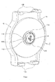
FIG. 1 is a front perspective view of a storage device according to a first embodiment of the present invention. -
FIG. 2 is a front perspective view of a holder according to the first embodiment of the present invention. -
FIG. 3 is a rear perspective view of the holder according to the first embodiment of the present invention. -
FIG. 4 is a front perspective view of a reel according to the first embodiment of the present invention. -
FIG. 5 is a rear perspective view of the reel according to the first embodiment of the present invention. -
FIG. 6 is a sectional view of the reel according to the first embodiment of the present invention. -
FIG. 7 is a rear perspective view of the storage device according to the first embodiment of the present invention. -
FIG. 8 is a front view of a holder according to a second embodiment of the present invention. -
FIG. 9 is a front perspective view of a holder according to a third embodiment of the present invention. -
FIG. 10 is a rear perspective view of a reel according to the third embodiment of the present invention. -
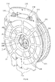
FIG. 11 is a front perspective view of a storage device according to a fourth embodiment of the present invention. -
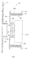
FIG. 12 is a sectional view of the storage device according to the fourth embodiment of the present invention. - 1... storage device, 3...charging cable, 3A... charging control box, 3B...terminal-side cable, 3C...wound-up-side cable, 3D...terminal connector, 3E...vehicle-side connector, 10...holder, 11...holder-side socket, 11A...guide portion, 11B...incline, 13A...power-supply-side cable, 13...contact box, 15...holder main body, 15A...support portion, 15B...hook portion, 15C...arm portion, 15D...arm portion, 15E..concave portion, 15F...protruding portion, 17...attachment, 20...reel, 21...back plate, 21A...concave portion, 21B...engagement portion, 21C...protruding portion, 21E...grip portion, 21D...release button, 21F...support portion, 21G...locking hook portion, 23...rotating drum, 23A...drum plate, 23B...wind-up rim, 23C... flange portion, 23D... fitting portion, 23E...fixing portion, 23F...cable-side connector, 23G...handle portion, 25...reel-side socket, 25A...guide portion, Mh... identification mark, Mr... identification mark
- As shown in
FIG. 1 , astorage device 1 according to the present embodiment is a device to store acharging cable 3 for an electrically-driven vehicle (a plug-in hybrid vehicle and the like). - As shown in
FIG. 1 , thestorage device 1 according to the present embodiment is configured to include aholder 10, areel 20, and the like. Thereel 20 is attachable to and detachable from theholder 10. Thereel 20 has to be attached to theholder 10 when charging of an electrically-driven vehicle is performed. - As shown in
FIG. 2 , theholder 10 is provided with a holder-side socket 11 to be electrically connected to a side of a charging power supply (not shown). The holder-side socket 11 is arranged substantially in the center of theholder 10 in a rotatable manner. - The holder-
side socket 11 is electrically connected to a power-supply-side cable 13A via a sliding contact such as a slip ring (not shown) provided within acontact box 13 of a disk shape, as shown inFIG. 3 . This allows the holder-side socket 11 to rotate with respect to theholder 10 while securing continuity with the power-supply-side cable 13A. - The power-supply-
side cable 13A is a cable to electrically connect the charging power supply and the holder-side socket 11 to each other. The power-supply-side cable 13A is connected to a fixed-side brush (not shown) of the slip ring (not shown). On the other hand, a rotating-side electrode ring (not shown) of the slip ring (not shown) is connected to the holder-side socket 11. - The
contact box 13 is coupled to a holdermain body 15. As shown inFIG. 2 , asupport portion 15A and ahook portion 15B to fix thereel 20 to theholder 10 are respectively provided at a bottom end side and a top end side of the holdermain body 15. - The
support portion 15A supports a bottom end side of thereel 20, whereas thehook portion 15B is engaged with a top end side of thereel 20 to hold the top end side. This allows the entirety of thereel 20 to be held by thesupport portion 15A and thehook portion 15B. - As shown in
FIG. 1 , thesupport portion 15A includes anarm portion 15C. Thearm portion 15C protrudes from the holdermain body 15 toward thereel 20, and has aconcave portion 15E at a protruding side. Thehook portion 15B includes anarm portion 15D. Thearm portion 15D is a hook-like member that protrudes from the holdermain body 15 toward thereel 20 and that has a protrudingportion 15F at a leading end side of thearm portion 15D in a protruding direction thereof. - As shown in
FIG. 5 , provided in aback plate 21 of thereel 20 are aconcave portion 21A capable of being engaged with theconcave portion 15E in thesupport portion 15A, and anengagement portion 21B having a hole shape capable of being engaged with thehook portion 15B. - A protruding portion 21C to be engaged with the protruding
portion 15F is provided in theengagement portion 21B. The protruding portion 21C is pressed by a spring (not shown) against a position in which engagement with the protrudingportion 15F is enabled. - When the
reel 20 is being attached to theholder 10, theconcave portion 21A of thereel 20 is fitted to thesupport portion 15A, and in such a state, thereel 20 is caused to swing about thesupport portion 15A as a supporting point such that thereel 20 is pressed toward theholder 10. In this way, thehook portion 15B is fitted into theengagement portion 21B, and the protruding portion 21C in thereel 20 and the protrudingportion 15F in theholder 10 are engaged with each other. As a result, thereel 20 is fixed to theholder 10. - When the
reel 20 is being detached from theholder 10, the engagement between the protruding portion 21C and the protrudingportion 15F is released by operation of arelease button 21D provided to agrip portion 21E of the reel 20 (the back plate 21). In such a state, thereel 20 only has to be caused to swing about thesupport portion 15A as a supporting point so as to be spaced apart from theholder 10. - As shown in
FIG. 4 , thereel 20 is configured to include arotating drum 23 to wind up the chargingcable 3, theback plate 21 to rotatably support therotating drum 23, and the like. - As shown in
FIG. 6 , therotating drum 23 is configured to include adrum plate 23A of a disk shape, a wind-uprim 23B formed in a ring shape, aflange portion 23C of a brim-like shape provided to the wind-uprim 23B, and the like. In the present embodiment, thedrum plate 23A, the wind-uprim 23B, theflange portion 23C, and the like are integrally formed of resin. - The
drum plate 23A has afitting portion 23D provided thereto. Thefitting portion 23D is configured such that asupport portion 21F having a cylindrical shape provided to theback plate 21 is fitted into thefitting portion 23D in a slidably contacting manner. Therotating drum 23 can rotate with respect to theback plate 21 due to the sliding contact between aninner periphery 23d of thefitting portion 23D and anouter periphery 21f of thesupport portion 21F. - As shown in
FIG. 4 , a fixingportion 23E, by which acharging control box 3A is fixed, is provided at an inner peripheral side of the wind-uprim 23B. The chargingcontrol box 3A contains a built-in control circuit (CCID: Charge Circuit Interrupt Device, or the like) performing charging control. The chargingcontrol box 3A is provided in an electrical circuit (in an electrical path) connecting the charging power supply and the electrically-driven vehicle to each other. - In many cases, the charging
control box 3A is supplied as part of the chargingcable 3 by a vehicle manufacturer or the like. Hereinafter, the chargingcable 3 situated closer to the charging power source in relation to the chargingcontrol box 3A is referred to as a terminal-side cable 3B, and the chargingcable 3 situated closer to the electrically-driven vehicle in relation to the chargingcontrol box 3A is referred to as a wound-up-side cable 3C. - A
terminal connector 3D for connection to a side of the power supply is provided at an end of the terminal-side cable 3B, whereas a vehicle-side connector 3E for connection to the electrically-driven vehicle is provided at an end of the wound-up-side cable 3C. - The charging
cable 3 according to the present embodiment is configured to include the chargingcontrol box 3A, the terminal-side cable 3B, the wound-up-side cable 3C, theterminal connector 3D, the vehicle-side connector 3E, and the like. - A cable-
side connector 23F to which theterminal connector 3D can be attached is provided on a side of the fixingportion 23E of thedrum plate 23A, whereas, as shown inFIG. 7 , a reel-side socket 25 is provided on a side of theholder 10 of thedrum plate 23A. The reel-side socket 25 is electrically connected to the cable-side connector 23F, and can be fitted to the holder-side socket 11. - Therefore, when the holder-
side socket 11 and the reel-side socket 25 are fitted to each other in a state in which theterminal connector 3D is attached to the cable-side connector 23F, the chargingcable 3 and the power-supply-side cable 13A become conductible with each other. - When the wound-up-
side cable 3C wound up around therotating drum 23 is let out, the holder-side socket 11 and the reel-side socket 25 are rotated in conjunction with the rotation of therotating drum 23. Nevertheless, the conduction state between the chargingcable 3 and the power-supply-side cable 13A is maintained by means of the slip ring (not shown) provided in thecontact box 13. - The
back plate 21 has alocking hook portion 21G provided thereto that locks an end side of the wound-up-side cable 3C. Therefore, in a state in which the end side of the wound-up-side cable 3C is locked by the lockinghook portion 21G, even when therotating drum 23 rotates, there is no possibility that the wound-up-side cable 3C, which has been reeled in, becomes so loose. - As shown in
FIGS. 2 and5 , respectively, the holder-side socket 11 and the reel-side socket 25 are asymmetric with respect to a central axis of rotation, and thus, it is necessary to adjust a position of the reel-side socket 25 with respect to the holder-side socket 11 in order to fit the bothsockets - Specifically, when the
rotating drum 23 rotates with respect to theback plate 21 after thereel 20 is detached from theholder 10, the reel-side socket 25 rotates. Thus, when thereel 20 is being attached to theholder 10 on the next occasion, the reel-side socket 25 cannot be fitted to the holder-side socket 11. - Therefore, in the present embodiment, identification marks Mh and Mr indicating a position in which the both
sockets holder 10 and thereel 20, respectively, as shown inFIGS. 2 and4 . - Specifically, as shown in
FIG. 4 , the identification mark Mr on thereel 20 is provided on an outer peripheral side of thereel 20. More specifically, theflange portion 23C has ahandle portion 23G of a cylinder-like shape provided thereto that is gripped by a user when rotating therotating drum 23, and the identification mark Mr is provided on a root side of thehandle portion 23G. - As shown in
FIG. 2 , the identification mark Mh on theholder 10 is provided on an outermost peripheral part of the holder-side socket 11. Although the identification mark Mh is not viewable in a state in which thereel 20 is attached to theholder 10, the identification mark Mh can be observed visually from a side of thereel 20 in the process of attaching thereel 20 to theholder 10. - The identification marks Mh and Mr according to the present embodiment include a figure (a triangular figure in the present embodiment) colored with a color different from the ground color of the regions where the identification marks Mh and Mr are provided.
- In the present embodiment, the charging cable 3 (the wound-up-
side cable 3C) is stored in a wound-up state, and thereel 20 can be attached to and detached from theholder 10. Therefore, theholder 10 may be set in a place, such as a garage and a parking lot, where charging can be performed, and solely thereel 20 may be stored in the trunk or the like. - When the
rotating drum 23 rotates to cause the reel-side socket 25 to rotate in a state in which thereel 20 is detached from theholder 10, there is a possibility that the reel-side socket 25 cannot be fitted to the holder-side socket 11 when thereel 20 is being attached to theholder 10, as described above. - To cope with this, in the present embodiment, the identification marks Mh and Mr indicating the position in which the both
sockets holder 10 and thereel 20, respectively. Therefore, even in a case where the position of the reel-side socket 25 with respect to the holder-side socket 11 has been displaced, the reel-side socket 25 can be fitted to the holder-side socket 11 by rotating the rotatable socket (the reel-side socket 25 in the present embodiment) using the identification marks Mh and Mr as guides. - As described above, in the present embodiment, by allowing the
reel 20 to be attachable to and detachable from theholder 10, the reel-side socket 25 can be easily fitted to the holder-side socket 11 and workability for attaching thereel 20 can be improved, while storability and loadability of the chargingcable 3 is improved. - In a case where the position of the reel-
side socket 25 is displaced with respect to the position of the holder-side socket 11, it is necessary to operate thehandle portion 23G to thereby rotate the holder-side socket 11. Since the identification mark Mr is provided on thehandle portion 23G, it is possible to operate thehandle portion 23G while visually observing the identification mark Mr with ease. - The present second embodiment is an example in which the identification mark Mh on the
holder 10 is provided on an outer peripheral side of theholder 10, as shown inFIG. 8 . Specifically, this is an example in which the identification mark Mh is provided in a position visually observable from the side of thereel 20 even in a state in which thereel 20 is attached to theholder 10. - The present second embodiment is an example in which an
attachment 17 of a disk shape, on which the identification mark Mh is placed, is assembled to the holder-side socket 11. However, the present second embodiment is not limited to this. The identification mark Mh may be provided on an outer peripheral side of an outer periphery of theholder 10, which outer periphery is made wider than that in the first embodiment. - As shown in
FIGS. 9 and10 , in the present third embodiment, a plurality ofguide portions 11A are provided to the holder 10 (seeFIG. 9 ), and a plurality ofguide portions 25A are provided to the reel 20 (seeFIG. 10 ). The plurality ofguide portions 11A and the plurality ofguide portions 25A are members capable of respectively guiding the holder-side socket 11 and the reel-side socket 25 to the position in which the holder-side socket 11 and the reel-side socket 25 can be fitted to each other. - Specifically, as shown in
FIG. 9 , the plurality ofguide portions 11A are provided so as to surround a rotational center of the holder-side socket 11 concentrically with the rotational center. - More specifically, the plurality of
guide portions 11A are provided around the holder-side socket 11 in such a manner that an outer peripheral side of the holder-side socket 11 is divided into three in a circumferential direction thereof centered at the rotational center of the holder-side socket 11. In the present embodiment, the plurality ofguide portions 11A are three in number. Each of the plurality ofguide portions 11A is configured in a triangle-like shape pointed on a side of thereel 20 so as to have inclines 11B inclined with respect to an insertion direction of the reel 20 (shown by an arrow X inFIG. 9 ). - The plurality of
guide portions 25A in thereel 20 are provided so as to surround a rotational center of the reel-side socket 25 concentrically with the rotational center, in a similar manner to that in the plurality ofguide portions 11 A. - Specifically, as shown in
FIG. 10 , the plurality ofguide portions 25A are provided around the reel-side socket 25 in such a manner that an outer peripheral side of the reel-side socket 25 is divided into three in a circumferential direction thereof centered at the rotational center of thereel 20. In the present embodiment, the plurality ofguide portions 25A are three in number. Each of the plurality ofguide portions 25A is configured in a triangle-like shape protruding toward a side of theholder 10 so as to have inclines 25B inclined with respect to an insertion direction of the holder 10 (shown by an arrow Y inFIG. 10 ). - Due to the above, in the present third embodiment, the
reel 20 can be attached to the holder easily and reliably because thesockets sockets reel 20 to theholder 10. - In the present third embodiment, the identification marks Mh and Mr according to the first embodiment or the second embodiment are not provided. However, the identification marks Mh and Mr may be provided similarly to the first embodiment or the second embodiment.
- Although the
terminal connector 3D is electrically connected to the reel-side socket 25 via the cable-side connector 23F in the above-described embodiments, the cable-side connector 23F and the reel-side socket 25 are not provided in the present fourth embodiment. Instead, theterminal connector 3D is configured to be directly fitted into the holder-side socket 11. - Specifically, in the present fourth embodiment, a plurality of fixing
portions 23H to fix the chargingcontrol box 3A to theflange portion 23C are provided as shown inFIG. 11 . The plurality of fixingportions 23H are arranged so that the center of volume of the chargingcontrol box 3A is positioned on a rotational center axis L1 of the rotating drum 23 (or in the vicinity of the rotational center axis L1). "The center of volume" means a point where a volume moment (a moment due to gravity when a density is assumed to be "1") is balanced. - In the present fourth embodiment, the center of volume is not positioned perfectly on the rotational center axis L1, and the center of volume deviates to the left side of the drawing sheet with respect to the rotational center axis L1. "The center of volume of the charging
control box 3A is positioned on the rotational center axis L1" means not only a case where the center of volume is positioned perfectly on the rotational center axis L1 as a matter of course, but also a case where the center of volume deviates from the rotational center axis L1 to the extent that a large rotational imbalance does not occur. - "The deviation to the extent that a large rotational imbalance does not occur" means, for example, a deviation approximately equal to or less than one-half of a sum of a width dimension W1 of the charging
control box 3A and a width dimension W2 of theterminal connector 3D, in a case where the chargingcontrol box 3A has a rectangular tube-like shape. - A
connector portion 27 for connection of theterminal connector 3D to the power supply side is provided in a position that is on the same side as a side on which the plurality of fixingportions 23H are positioned in therotating drum 23 and that deviates with respect to the rotational center axis L1 in a direction orthogonal to the rotational center axis L1. - As shown in
FIG. 12 , anattachment port 27A for attachment of theterminal connector 3D to the holder-side socket 11 is provided in theconnector portion 27. Theattachment port 27A penetrates through therotating drum 23 and theback plate 21 in a direction parallel to the rotational center axis L1, and thereby communicates with a side of the holder-side socket 11 of theholder 10. - The
connector portion 27 has at least one lockingportion 27B provided. The lockingportion 27B suppresses theterminal connector 3D from falling off from therotating drum 23, i.e., from thereel 20. - The locking
portion 27B according to the present fourth embodiment is configured to include alocking hook 27C and aresilient portion 27D, for example. Thelocking hook 27C is formed in an arm-like shape as a whole, and one end thereof is formed in a hook-like shape. Specifically, the lockinghook 27C has aprotrusion 27F to be engaged with a lockedportion 27E provided on theterminal connector 3D. Theprotrusion 27F is provided at one end side of thelocking hook 27C in a longitudinal direction thereof. A middle portion of thelocking hook 27C in the longitudinal direction thereof is swingably coupled to therotating drum 23. - The
resilient portion 27D applies an elastic force that retains a locking state between theprotrusion 27F and the lockedportion 27E to the other end side of thelocking hook 27C in the longitudinal direction thereof. Theresilient portion 27D according to the present fourth embodiment includes at least one coil spring. - The
attachment port 27A has, at a side of the holder-side socket 11 thereof, at least one protrudingportion 27G provided that locks theterminal connector 3D inserted into theattachment port 27A. The protrudingportion 27G is a region protruding from an inner periphery of theattachment port 27A toward the center thereof. - Upon insertion of the
terminal connector 3D into theattachment port 27A, theterminal connector 3D is locked by the protrudingportion 27G, and thus, theterminal connector 3D is suppressed from penetrating out to a side of theholder 10. In addition, since theterminal connector 3D is in a state held between the protrudingportion 27G and thelocking hook 27C, theterminal connector 3D is suppressed from falling off from thereel 20. - In the above-described embodiments, the holder-
side socket 11 and the reel-side socket 25 are both rotatable. However, the present invention is not limited to this, and it is acceptable that at least either the holder-side socket 11 or the reel-side socket 25 is rotatable. For example, in a configuration in which the holder-side socket 11 is not rotatable, the identification mark Mh may be provided on the holdermain body 15. - In the above-described embodiments, the
terminal connector 3D is electrically connected to the reel-side socket 25 via the cable-side connector 23F. However, the present invention is not limited to this and, for example, theterminal connector 3D itself may be caused to function as the reel-side socket 25 by fixing theterminal connector 3D in the position of the reel-side socket 25. - In the above-described embodiments, the charging
control box 3A is fixed to thedrum plate 23A. However, the present invention is not limited to this and, for example, the chargingcontrol box 3A may be configured to be fixed to the wind-uprim 23B. - In the above-described embodiments, the identification marks Mh and Mr include a figure colored with a color different from the ground color of the regions where the identification marks Mh and Mr are provided. However, the present invention is not limited to this and, for example, the identification marks Mh and Mr may include a convex portion, a concave portion (including a through-hole), or the like. According to the identification marks Mh and Mr that include such a convex portion or concave portion, the identification marks Mh and Mr can be identified also by a sense of touch.
- In the above-described embodiments, the plurality of
guide portions guide portions guide portions - In the above-described embodiments, the example regarding the charging
cable 3 including the chargingcontrol box 3A has been described. However, the present invention is not limited to this, and can also be applied to the chargingcable 3 not including the chargingcontrol box 3A. - The present invention only has to be consistent with the spirit of the invention described in the claims, and is not limited to the above-described embodiments.
Claims (10)
- A charging-cable storage device configured to store a charging cable for use in an electrically-driven vehicle having an electric motor for traveling, the device comprising:a holder-side socket to be electrically connected to a side of a charging power supply;a holder provided with the holder-side socket;a reel that is attachably and detachably attached to the holder and that comprises a rotating drum to wind up the charging cable; anda reel-side socket that is provided to the reel and fitted to the holder-side socket to thereby electrically connect the side of the charging power supply and the charging cable to each other,wherein at least either the holder-side socket or the reel-side socket is rotatable, andwherein the holder and the reel are provided with respective identification marks indicating a position in which the reel-side socket is fittable to the holder-side socket.
- The storage device according to claim 1,
wherein the identification mark on the holder is provided in a position visually observable from a side of the reel in a process of attaching the reel to the holder. - The storage device according to claim 1 or 2,
wherein the identification mark on the holder is provided on an outer peripheral side of the holder. - The storage device according to any one of claims 1 to 3,
wherein the identification mark on the reel is provided on an outer peripheral side of the reel. - The storage device according to any one of claims 1 to 4,
wherein the reel-side socket rotates in conjunction with the rotating drum, wherein a handle portion to rotate the rotating drum is provided to the reel, and wherein the identification mark on the reel is provided to the handle portion. - A charging-cable storage device configured to store a charging cable for use in an electrically-driven vehicle having an electric motor for traveling, the device comprising:a holder-side socket to be electrically connected to a side of a charging power supply;a holder provided with the holder-side socket;a reel that is attachably and detachably attached to the holder and that comprises a rotating drum to wind up the charging cable; anda reel-side socket that is provided to the reel and fitted to the holder-side socket to thereby electrically connect the side of the charging power supply and the charging cable to each other,wherein at least either the holder-side socket or the reel-side socket is rotatable, andwherein the holder-side socket and the reel-side socket have respective guide portions provided thereto that guide either the holder-side socket or the reel-side socket to a position in which fit to the other socket is enabled.
- The storage device according to claim 6,
wherein the guide portion comprises inclines inclined with respect to an insertion direction of the reel. - The storage device according to claim 6 or 7,
wherein the guide portion on the holder-side socket and the guide portion on the reel-side socket are each provided in a plurality of positions so as to surround a rotational center of each socket concentrically with the rotational center. - The storage device according to claim 8,
wherein the guide portion is provided in plurality and is arranged so as to divide a circumference centered at the rotational center into three in a circumferential direction. - The storage device according to any one of claims 6 to 9,
wherein the holder and the reel are provided with respective identification marks indicating a position in which the reel-side socket is fittable to the holder-side socket.
Applications Claiming Priority (3)
| Application Number | Priority Date | Filing Date | Title |
|---|---|---|---|
| JP2012018559 | 2012-01-31 | ||
| JP2012121003A JP2013179817A (en) | 2012-01-31 | 2012-05-28 | Charge cable housing device |
| PCT/JP2012/076225 WO2013114679A1 (en) | 2012-01-31 | 2012-10-10 | Charging-cable storage device |
Publications (1)
| Publication Number | Publication Date |
|---|---|
| EP2811602A1 true EP2811602A1 (en) | 2014-12-10 |
Family
ID=48904745
Family Applications (1)
| Application Number | Title | Priority Date | Filing Date |
|---|---|---|---|
| EP12867438.9A Withdrawn EP2811602A1 (en) | 2012-01-31 | 2012-10-10 | Charging-cable storage device |
Country Status (5)
| Country | Link |
|---|---|
| US (1) | US20150008274A1 (en) |
| EP (1) | EP2811602A1 (en) |
| JP (1) | JP2013179817A (en) |
| CN (1) | CN104067470A (en) |
| WO (1) | WO2013114679A1 (en) |
Cited By (2)
| Publication number | Priority date | Publication date | Assignee | Title |
|---|---|---|---|---|
| WO2017153683A1 (en) | 2016-03-09 | 2017-09-14 | Commissariat A L'energie Atomique Et Aux Energies Alternatives | Cable reel for recharging an electric vehicle |
| AT15935U1 (en) * | 2016-09-07 | 2018-09-15 | Avl Ditest Gmbh | cable Reels |
Families Citing this family (14)
| Publication number | Priority date | Publication date | Assignee | Title |
|---|---|---|---|---|
| JP5737402B2 (en) * | 2011-07-14 | 2015-06-17 | トヨタ自動車株式会社 | Charging cable storage device |
| JP2013179818A (en) * | 2012-02-06 | 2013-09-09 | Chuo Spring Co Ltd | Charging cable housing |
| JP5990120B2 (en) | 2013-03-19 | 2016-09-07 | 矢崎総業株式会社 | Connector device |
| US20150097090A1 (en) * | 2013-10-03 | 2015-04-09 | Delphi Technologies, Inc. | Portable holder for an electric vehicle charger with an inline electronics module |
| US9346653B1 (en) * | 2014-11-20 | 2016-05-24 | Shenzhen Mindray Bio-Medical Electronics Co., Ltd. | Cord retractor |
| CN104528473B (en) * | 2014-12-15 | 2016-08-24 | 上海市计量测试技术研究院 | Optical fiber cable storage device |
| US9592991B1 (en) * | 2015-01-15 | 2017-03-14 | Joseph Keane | Cable reel system |
| US10120328B2 (en) * | 2015-07-30 | 2018-11-06 | Ricoh Company, Ltd. | Drive device and image forming apparatus incorporating the drive device |
| DE102017212438A1 (en) * | 2017-07-20 | 2019-01-24 | Audi Ag | Charging cable device for an electrically operated motor vehicle |
| CN207861634U (en) * | 2017-12-12 | 2018-09-14 | 蔚来汽车有限公司 | Wire take-up device and mobile energy-enhancing vehicle for mobile energy-enhancing vehicles |
| US20210238007A1 (en) * | 2020-01-31 | 2021-08-05 | Chargepoint, Inc. | Cable reel with automated connection |
| CN112435495A (en) * | 2020-11-23 | 2021-03-02 | 北京千乘科技有限公司 | Automatic test system based on millimeter wave radar emission intensity |
| CN112919237B (en) * | 2021-02-02 | 2022-08-19 | 士商(湖州)精密技术有限公司 | Electric winder and control method thereof |
| US20260091952A1 (en) * | 2024-10-01 | 2026-04-02 | Shenzhen Zeyiniu Technology Co., Ltd | Novel Wire Organizer and Winder thereof |
Family Cites Families (13)
| Publication number | Priority date | Publication date | Assignee | Title |
|---|---|---|---|---|
| US4725697A (en) * | 1986-08-28 | 1988-02-16 | Alert Stamping & Mfg. Co., Inc. | Extension cord reel and case |
| US6170775B1 (en) * | 1999-06-03 | 2001-01-09 | Alert Stamping & Mfg. Co., Inc. | Electrical cord reel |
| US6273354B1 (en) * | 1999-06-03 | 2001-08-14 | Alert Stamping & Mfg. Co., Inc. | Retracting extension cord reel |
| JP4540778B2 (en) * | 1999-11-10 | 2010-09-08 | ナイルス株式会社 | Rotating connector device |
| US7114603B2 (en) * | 2004-12-02 | 2006-10-03 | Li-Chun Lai | Extension cord holder |
| US7438258B2 (en) * | 2006-01-18 | 2008-10-21 | Chi-Wen Chen | Reel device for winding an electrical cable thereon |
| WO2010023527A2 (en) * | 2008-08-26 | 2010-03-04 | Panasonic Electric Works Co., Ltd. | Electric vehicle charging cord set |
| JP2010052861A (en) * | 2008-08-26 | 2010-03-11 | Panasonic Electric Works Co Ltd | Code set for charging electric vehicle |
| JP5408765B2 (en) | 2008-11-07 | 2014-02-05 | 日東工業株式会社 | Car charging connection cable storage box and charging device |
| JP2010118224A (en) * | 2008-11-12 | 2010-05-27 | Hirose Electric Co Ltd | Connector having incorrect-insertion preventing function |
| US7984798B1 (en) * | 2009-12-31 | 2011-07-26 | John Ernest Hall | Electric cord reel |
| JP5557600B2 (en) * | 2010-05-21 | 2014-07-23 | トヨタホーム株式会社 | Charging cable storage device |
| CN103828162B (en) * | 2011-09-26 | 2016-01-20 | 丰田自动车株式会社 | Cable Winding Device |
-
2012
- 2012-05-28 JP JP2012121003A patent/JP2013179817A/en active Pending
- 2012-10-10 US US14/374,962 patent/US20150008274A1/en not_active Abandoned
- 2012-10-10 CN CN201280067740.6A patent/CN104067470A/en active Pending
- 2012-10-10 EP EP12867438.9A patent/EP2811602A1/en not_active Withdrawn
- 2012-10-10 WO PCT/JP2012/076225 patent/WO2013114679A1/en not_active Ceased
Non-Patent Citations (1)
| Title |
|---|
| See references of WO2013114679A1 * |
Cited By (3)
| Publication number | Priority date | Publication date | Assignee | Title |
|---|---|---|---|---|
| WO2017153683A1 (en) | 2016-03-09 | 2017-09-14 | Commissariat A L'energie Atomique Et Aux Energies Alternatives | Cable reel for recharging an electric vehicle |
| FR3048826A1 (en) * | 2016-03-09 | 2017-09-15 | Commissariat Energie Atomique | DEVICE FOR RECHARGING ELECTRIC VEHICLE. |
| AT15935U1 (en) * | 2016-09-07 | 2018-09-15 | Avl Ditest Gmbh | cable Reels |
Also Published As
| Publication number | Publication date |
|---|---|
| US20150008274A1 (en) | 2015-01-08 |
| JP2013179817A (en) | 2013-09-09 |
| WO2013114679A1 (en) | 2013-08-08 |
| CN104067470A (en) | 2014-09-24 |
Similar Documents
| Publication | Publication Date | Title |
|---|---|---|
| EP2811602A1 (en) | Charging-cable storage device | |
| EP2814128A1 (en) | Apparatus for housing charging cable | |
| EP2733804A1 (en) | Charging cable storage device | |
| CN112172561B (en) | Charging cable system for electric vehicle, electric vehicle and charging method thereof | |
| JP5877108B2 (en) | Cable housing device | |
| CN107453093B (en) | Charging terminal cover for charging cord management | |
| US5445252A (en) | Charge cord and retraction system for electric vehicle | |
| US9812820B2 (en) | Electrical connector and returning jig | |
| CN205509528U (en) | Portable holder for electric vehicle charger with in-line electronics module | |
| WO2013115375A1 (en) | Charging-cable storage device | |
| US20140339352A1 (en) | Cable housing device | |
| CN104115362A (en) | Cable housing device | |
| CN103348551A (en) | Vehicle on-board cable and vehicle | |
| JP2012170234A (en) | Charging apparatus and charging equipment | |
| CN215580432U (en) | car charger | |
| AU2018288019A1 (en) | Cable management assembly | |
| JP2013247025A (en) | Housing device for charge cable | |
| JP2013176227A (en) | Charging connector connection structure | |
| US12300928B2 (en) | Connector retainer | |
| JP3043585U (en) | Cord winding device | |
| EP2441882A1 (en) | Improvements in and relating to an iron and a method thereof | |
| WO2013111869A1 (en) | Charging cable housing device | |
| US20260124942A1 (en) | Bracket configured to connect to charging unit and including charging cable holder | |
| JP6176026B2 (en) | Power supply connector for electric vehicles | |
| JP2017068909A (en) | vehicle |
Legal Events
| Date | Code | Title | Description |
|---|---|---|---|
| PUAI | Public reference made under article 153(3) epc to a published international application that has entered the european phase |
Free format text: ORIGINAL CODE: 0009012 |
|
| 17P | Request for examination filed |
Effective date: 20140813 |
|
| AK | Designated contracting states |
Kind code of ref document: A1 Designated state(s): AL AT BE BG CH CY CZ DE DK EE ES FI FR GB GR HR HU IE IS IT LI LT LU LV MC MK MT NL NO PL PT RO RS SE SI SK SM TR |
|
| AX | Request for extension of the european patent |
Extension state: BA ME |
|
| STAA | Information on the status of an ep patent application or granted ep patent |
Free format text: STATUS: THE APPLICATION HAS BEEN WITHDRAWN |
|
| 18W | Application withdrawn |
Effective date: 20150312 |