EP2811553A1 - Plastic-coated electrode for alkaline storage battery - Google Patents
Plastic-coated electrode for alkaline storage battery Download PDFInfo
- Publication number
- EP2811553A1 EP2811553A1 EP14170069.0A EP14170069A EP2811553A1 EP 2811553 A1 EP2811553 A1 EP 2811553A1 EP 14170069 A EP14170069 A EP 14170069A EP 2811553 A1 EP2811553 A1 EP 2811553A1
- Authority
- EP
- European Patent Office
- Prior art keywords
- electrode according
- copolymer
- tetrafluoroethylene
- ptfe
- electrode
- Prior art date
- Legal status (The legal status is an assumption and is not a legal conclusion. Google has not performed a legal analysis and makes no representation as to the accuracy of the status listed.)
- Granted
Links
- 239000011230 binding agent Substances 0.000 claims abstract description 42
- 229920000642 polymer Polymers 0.000 claims abstract description 38
- 229920001577 copolymer Polymers 0.000 claims abstract description 31
- QQONPFPTGQHPMA-UHFFFAOYSA-N propylene Natural products CC=C QQONPFPTGQHPMA-UHFFFAOYSA-N 0.000 claims abstract description 31
- 125000004805 propylene group Chemical group [H]C([H])([H])C([H])([*:1])C([H])([H])[*:2] 0.000 claims abstract description 28
- BFKJFAAPBSQJPD-UHFFFAOYSA-N tetrafluoroethene Chemical group FC(F)=C(F)F BFKJFAAPBSQJPD-UHFFFAOYSA-N 0.000 claims abstract description 28
- 239000011262 electrochemically active material Substances 0.000 claims abstract description 23
- 239000004020 conductor Substances 0.000 claims abstract description 16
- BFDHFSHZJLFAMC-UHFFFAOYSA-L nickel(ii) hydroxide Chemical compound [OH-].[OH-].[Ni+2] BFDHFSHZJLFAMC-UHFFFAOYSA-L 0.000 claims abstract description 16
- 229920002313 fluoropolymer Polymers 0.000 claims abstract description 11
- 229910052751 metal Inorganic materials 0.000 claims abstract description 10
- 239000002184 metal Substances 0.000 claims abstract description 10
- NIXOWILDQLNWCW-UHFFFAOYSA-N 2-Propenoic acid Natural products OC(=O)C=C NIXOWILDQLNWCW-UHFFFAOYSA-N 0.000 claims abstract description 7
- SMZOUWXMTYCWNB-UHFFFAOYSA-N 2-(2-methoxy-5-methylphenyl)ethanamine Chemical compound COC1=CC=C(C)C=C1CCN SMZOUWXMTYCWNB-UHFFFAOYSA-N 0.000 claims abstract description 5
- 239000004810 polytetrafluoroethylene Substances 0.000 claims description 65
- 229920001343 polytetrafluoroethylene Polymers 0.000 claims description 65
- 239000004743 Polypropylene Substances 0.000 claims description 58
- 229920002134 Carboxymethyl cellulose Polymers 0.000 claims description 56
- 239000001768 carboxy methyl cellulose Substances 0.000 claims description 51
- 235000010948 carboxy methyl cellulose Nutrition 0.000 claims description 51
- 239000008112 carboxymethyl-cellulose Substances 0.000 claims description 51
- -1 polytetrafluoroethylene Polymers 0.000 claims description 38
- PXHVJJICTQNCMI-UHFFFAOYSA-N Nickel Chemical compound [Ni] PXHVJJICTQNCMI-UHFFFAOYSA-N 0.000 claims description 34
- 239000000835 fiber Substances 0.000 claims description 31
- 239000000203 mixture Substances 0.000 claims description 30
- 229920001155 polypropylene Polymers 0.000 claims description 28
- 229910052759 nickel Inorganic materials 0.000 claims description 17
- ASKVAEGIVYSGNY-UHFFFAOYSA-L cobalt(ii) hydroxide Chemical compound [OH-].[OH-].[Co+2] ASKVAEGIVYSGNY-UHFFFAOYSA-L 0.000 claims description 16
- XLYOFNOQVPJJNP-UHFFFAOYSA-M hydroxide Chemical compound [OH-] XLYOFNOQVPJJNP-UHFFFAOYSA-M 0.000 claims description 16
- 229910021503 Cobalt(II) hydroxide Inorganic materials 0.000 claims description 15
- 239000003792 electrolyte Substances 0.000 claims description 10
- 229920002153 Hydroxypropyl cellulose Polymers 0.000 claims description 8
- HCDGVLDPFQMKDK-UHFFFAOYSA-N hexafluoropropylene Chemical group FC(F)=C(F)C(F)(F)F HCDGVLDPFQMKDK-UHFFFAOYSA-N 0.000 claims description 8
- 239000001863 hydroxypropyl cellulose Substances 0.000 claims description 8
- 235000010977 hydroxypropyl cellulose Nutrition 0.000 claims description 8
- 229920000663 Hydroxyethyl cellulose Polymers 0.000 claims description 7
- 239000004354 Hydroxyethyl cellulose Substances 0.000 claims description 7
- 235000019447 hydroxyethyl cellulose Nutrition 0.000 claims description 7
- 239000001866 hydroxypropyl methyl cellulose Substances 0.000 claims description 7
- 229920003088 hydroxypropyl methyl cellulose Polymers 0.000 claims description 7
- 235000010979 hydroxypropyl methyl cellulose Nutrition 0.000 claims description 7
- UFVKGYZPFZQRLF-UHFFFAOYSA-N hydroxypropyl methyl cellulose Chemical compound OC1C(O)C(OC)OC(CO)C1OC1C(O)C(O)C(OC2C(C(O)C(OC3C(C(O)C(O)C(CO)O3)O)C(CO)O2)O)C(CO)O1 UFVKGYZPFZQRLF-UHFFFAOYSA-N 0.000 claims description 7
- 150000001875 compounds Chemical class 0.000 claims description 6
- 239000004811 fluoropolymer Substances 0.000 claims description 6
- BLRPTPMANUNPDV-UHFFFAOYSA-N Silane Chemical compound [SiH4] BLRPTPMANUNPDV-UHFFFAOYSA-N 0.000 claims description 4
- PPBRXRYQALVLMV-UHFFFAOYSA-N Styrene Chemical compound C=CC1=CC=CC=C1 PPBRXRYQALVLMV-UHFFFAOYSA-N 0.000 claims description 4
- 125000002496 methyl group Chemical group [H]C([H])([H])* 0.000 claims description 4
- 229910000077 silane Inorganic materials 0.000 claims description 4
- 239000007787 solid Substances 0.000 claims description 4
- UWRZIZXBOLBCON-VOTSOKGWSA-N (e)-2-phenylethenamine Chemical compound N\C=C\C1=CC=CC=C1 UWRZIZXBOLBCON-VOTSOKGWSA-N 0.000 claims description 3
- 239000004593 Epoxy Substances 0.000 claims description 3
- CERQOIWHTDAKMF-UHFFFAOYSA-M Methacrylate Chemical compound CC(=C)C([O-])=O CERQOIWHTDAKMF-UHFFFAOYSA-M 0.000 claims description 3
- 150000001412 amines Chemical class 0.000 claims description 3
- 125000004965 chloroalkyl group Chemical group 0.000 claims description 3
- 125000000113 cyclohexyl group Chemical group [H]C1([H])C([H])([H])C([H])([H])C([H])(*)C([H])([H])C1([H])[H] 0.000 claims description 3
- 125000001495 ethyl group Chemical group [H]C([H])([H])C([H])([H])* 0.000 claims description 3
- 125000001449 isopropyl group Chemical group [H]C([H])([H])C([H])(*)C([H])([H])[H] 0.000 claims description 3
- 125000001997 phenyl group Chemical group [H]C1=C([H])C([H])=C(*)C([H])=C1[H] 0.000 claims description 3
- 125000000391 vinyl group Chemical group [H]C([*])=C([H])[H] 0.000 claims description 3
- 229920002554 vinyl polymer Polymers 0.000 claims description 3
- 229910052727 yttrium Inorganic materials 0.000 claims description 3
- VWQVUPCCIRVNHF-UHFFFAOYSA-N yttrium atom Chemical compound [Y] VWQVUPCCIRVNHF-UHFFFAOYSA-N 0.000 claims description 3
- PEVRKKOYEFPFMN-UHFFFAOYSA-N 1,1,2,3,3,3-hexafluoroprop-1-ene;1,1,2,2-tetrafluoroethene Chemical group FC(F)=C(F)F.FC(F)=C(F)C(F)(F)F PEVRKKOYEFPFMN-UHFFFAOYSA-N 0.000 claims description 2
- NIXOWILDQLNWCW-UHFFFAOYSA-M Acrylate Chemical compound [O-]C(=O)C=C NIXOWILDQLNWCW-UHFFFAOYSA-M 0.000 claims description 2
- VGGSQFUCUMXWEO-UHFFFAOYSA-N Ethene Chemical compound C=C VGGSQFUCUMXWEO-UHFFFAOYSA-N 0.000 claims description 2
- 239000005977 Ethylene Substances 0.000 claims description 2
- XTXRWKRVRITETP-UHFFFAOYSA-N Vinyl acetate Chemical compound CC(=O)OC=C XTXRWKRVRITETP-UHFFFAOYSA-N 0.000 claims description 2
- 229910052769 Ytterbium Inorganic materials 0.000 claims description 2
- 229910052758 niobium Inorganic materials 0.000 claims description 2
- 239000010955 niobium Substances 0.000 claims description 2
- GUCVJGMIXFAOAE-UHFFFAOYSA-N niobium atom Chemical compound [Nb] GUCVJGMIXFAOAE-UHFFFAOYSA-N 0.000 claims description 2
- 229910052712 strontium Inorganic materials 0.000 claims description 2
- CIOAGBVUUVVLOB-UHFFFAOYSA-N strontium atom Chemical compound [Sr] CIOAGBVUUVVLOB-UHFFFAOYSA-N 0.000 claims description 2
- NAWDYIZEMPQZHO-UHFFFAOYSA-N ytterbium Chemical compound [Yb] NAWDYIZEMPQZHO-UHFFFAOYSA-N 0.000 claims description 2
- UGZADUVQMDAIAO-UHFFFAOYSA-L zinc hydroxide Chemical compound [OH-].[OH-].[Zn+2] UGZADUVQMDAIAO-UHFFFAOYSA-L 0.000 claims description 2
- 229910021511 zinc hydroxide Inorganic materials 0.000 claims description 2
- 229940007718 zinc hydroxide Drugs 0.000 claims description 2
- XLYOFNOQVPJJNP-UHFFFAOYSA-N water Substances O XLYOFNOQVPJJNP-UHFFFAOYSA-N 0.000 description 32
- 239000000463 material Substances 0.000 description 20
- 239000004480 active ingredient Substances 0.000 description 17
- 229910000831 Steel Inorganic materials 0.000 description 15
- 239000010959 steel Substances 0.000 description 15
- 239000000654 additive Substances 0.000 description 14
- 229910017052 cobalt Inorganic materials 0.000 description 14
- 239000010941 cobalt Substances 0.000 description 14
- GUTLYIVDDKVIGB-UHFFFAOYSA-N cobalt atom Chemical compound [Co] GUTLYIVDDKVIGB-UHFFFAOYSA-N 0.000 description 14
- 239000000243 solution Substances 0.000 description 14
- HCHKCACWOHOZIP-UHFFFAOYSA-N Zinc Chemical compound [Zn] HCHKCACWOHOZIP-UHFFFAOYSA-N 0.000 description 13
- 238000002156 mixing Methods 0.000 description 13
- SIWVEOZUMHYXCS-UHFFFAOYSA-N oxo(oxoyttriooxy)yttrium Chemical compound O=[Y]O[Y]=O SIWVEOZUMHYXCS-UHFFFAOYSA-N 0.000 description 13
- 239000011701 zinc Substances 0.000 description 13
- 229910052725 zinc Inorganic materials 0.000 description 13
- 229910005813 NiMH Inorganic materials 0.000 description 9
- KWYUFKZDYYNOTN-UHFFFAOYSA-M Potassium hydroxide Chemical compound [OH-].[K+] KWYUFKZDYYNOTN-UHFFFAOYSA-M 0.000 description 9
- 238000002360 preparation method Methods 0.000 description 9
- 239000000843 powder Substances 0.000 description 8
- 238000012360 testing method Methods 0.000 description 8
- WMFOQBRAJBCJND-UHFFFAOYSA-M Lithium hydroxide Chemical compound [Li+].[OH-] WMFOQBRAJBCJND-UHFFFAOYSA-M 0.000 description 7
- 239000006260 foam Substances 0.000 description 7
- 239000006185 dispersion Substances 0.000 description 5
- 238000007254 oxidation reaction Methods 0.000 description 5
- HEMHJVSKTPXQMS-UHFFFAOYSA-M Sodium hydroxide Chemical compound [OH-].[Na+] HEMHJVSKTPXQMS-UHFFFAOYSA-M 0.000 description 3
- 239000011149 active material Substances 0.000 description 3
- 150000004649 carbonic acid derivatives Chemical class 0.000 description 3
- 238000001035 drying Methods 0.000 description 3
- 229940082150 encore Drugs 0.000 description 3
- 230000003647 oxidation Effects 0.000 description 3
- 239000002245 particle Substances 0.000 description 3
- 238000012549 training Methods 0.000 description 3
- 229910005580 NiCd Inorganic materials 0.000 description 2
- 229910003962 NiZn Inorganic materials 0.000 description 2
- 229910052782 aluminium Inorganic materials 0.000 description 2
- XAGFODPZIPBFFR-UHFFFAOYSA-N aluminium Chemical compound [Al] XAGFODPZIPBFFR-UHFFFAOYSA-N 0.000 description 2
- 230000000903 blocking effect Effects 0.000 description 2
- 239000011575 calcium Substances 0.000 description 2
- 230000015556 catabolic process Effects 0.000 description 2
- 239000011248 coating agent Substances 0.000 description 2
- 238000000576 coating method Methods 0.000 description 2
- 239000010949 copper Substances 0.000 description 2
- 230000001351 cycling effect Effects 0.000 description 2
- 238000006731 degradation reaction Methods 0.000 description 2
- 125000003700 epoxy group Chemical group 0.000 description 2
- 238000011156 evaluation Methods 0.000 description 2
- 239000011777 magnesium Substances 0.000 description 2
- 239000011572 manganese Substances 0.000 description 2
- 238000004519 manufacturing process Methods 0.000 description 2
- 239000002609 medium Substances 0.000 description 2
- 238000013508 migration Methods 0.000 description 2
- 230000005012 migration Effects 0.000 description 2
- 239000000178 monomer Substances 0.000 description 2
- 101100389815 Caenorhabditis elegans eva-1 gene Proteins 0.000 description 1
- OYPRJOBELJOOCE-UHFFFAOYSA-N Calcium Chemical compound [Ca] OYPRJOBELJOOCE-UHFFFAOYSA-N 0.000 description 1
- BVKZGUZCCUSVTD-UHFFFAOYSA-L Carbonate Chemical compound [O-]C([O-])=O BVKZGUZCCUSVTD-UHFFFAOYSA-L 0.000 description 1
- RYGMFSIKBFXOCR-UHFFFAOYSA-N Copper Chemical compound [Cu] RYGMFSIKBFXOCR-UHFFFAOYSA-N 0.000 description 1
- MYMOFIZGZYHOMD-UHFFFAOYSA-N Dioxygen Chemical compound O=O MYMOFIZGZYHOMD-UHFFFAOYSA-N 0.000 description 1
- UFHFLCQGNIYNRP-UHFFFAOYSA-N Hydrogen Chemical compound [H][H] UFHFLCQGNIYNRP-UHFFFAOYSA-N 0.000 description 1
- 229910012851 LiCoO 2 Inorganic materials 0.000 description 1
- FYYHWMGAXLPEAU-UHFFFAOYSA-N Magnesium Chemical compound [Mg] FYYHWMGAXLPEAU-UHFFFAOYSA-N 0.000 description 1
- PWHULOQIROXLJO-UHFFFAOYSA-N Manganese Chemical compound [Mn] PWHULOQIROXLJO-UHFFFAOYSA-N 0.000 description 1
- 239000004952 Polyamide Substances 0.000 description 1
- 239000013543 active substance Substances 0.000 description 1
- 239000000853 adhesive Substances 0.000 description 1
- 230000001070 adhesive effect Effects 0.000 description 1
- 229910045601 alloy Inorganic materials 0.000 description 1
- 239000000956 alloy Substances 0.000 description 1
- 239000012736 aqueous medium Substances 0.000 description 1
- 239000007864 aqueous solution Substances 0.000 description 1
- QVGXLLKOCUKJST-UHFFFAOYSA-N atomic oxygen Chemical compound [O] QVGXLLKOCUKJST-UHFFFAOYSA-N 0.000 description 1
- 230000015572 biosynthetic process Effects 0.000 description 1
- 229910052793 cadmium Inorganic materials 0.000 description 1
- BDOSMKKIYDKNTQ-UHFFFAOYSA-N cadmium atom Chemical compound [Cd] BDOSMKKIYDKNTQ-UHFFFAOYSA-N 0.000 description 1
- 229910052791 calcium Inorganic materials 0.000 description 1
- 150000001869 cobalt compounds Chemical class 0.000 description 1
- IVMYJDGYRUAWML-UHFFFAOYSA-N cobalt(II) oxide Inorganic materials [Co]=O IVMYJDGYRUAWML-UHFFFAOYSA-N 0.000 description 1
- 229910052802 copper Inorganic materials 0.000 description 1
- 238000007728 cost analysis Methods 0.000 description 1
- 239000013078 crystal Substances 0.000 description 1
- 230000007423 decrease Effects 0.000 description 1
- 230000006866 deterioration Effects 0.000 description 1
- 238000011161 development Methods 0.000 description 1
- 229910001882 dioxygen Inorganic materials 0.000 description 1
- 238000009826 distribution Methods 0.000 description 1
- 230000000694 effects Effects 0.000 description 1
- 229920001971 elastomer Polymers 0.000 description 1
- 239000000806 elastomer Substances 0.000 description 1
- 238000006056 electrooxidation reaction Methods 0.000 description 1
- 239000005038 ethylene vinyl acetate Substances 0.000 description 1
- 125000000524 functional group Chemical group 0.000 description 1
- 150000004678 hydrides Chemical class 0.000 description 1
- 150000004679 hydroxides Chemical class 0.000 description 1
- 230000003993 interaction Effects 0.000 description 1
- 229910000765 intermetallic Inorganic materials 0.000 description 1
- 230000002427 irreversible effect Effects 0.000 description 1
- 229910052749 magnesium Inorganic materials 0.000 description 1
- 229910052748 manganese Inorganic materials 0.000 description 1
- 238000000034 method Methods 0.000 description 1
- 239000012811 non-conductive material Substances 0.000 description 1
- 230000001590 oxidative effect Effects 0.000 description 1
- 239000001301 oxygen Substances 0.000 description 1
- 229910052760 oxygen Inorganic materials 0.000 description 1
- 229920001200 poly(ethylene-vinyl acetate) Polymers 0.000 description 1
- 229920002647 polyamide Polymers 0.000 description 1
- 229920000098 polyolefin Polymers 0.000 description 1
- 238000006722 reduction reaction Methods 0.000 description 1
- VSZWPYCFIRKVQL-UHFFFAOYSA-N selanylidenegallium;selenium Chemical compound [Se].[Se]=[Ga].[Se]=[Ga] VSZWPYCFIRKVQL-UHFFFAOYSA-N 0.000 description 1
- 239000006104 solid solution Substances 0.000 description 1
- 238000003756 stirring Methods 0.000 description 1
- 239000000126 substance Substances 0.000 description 1
- JBQYATWDVHIOAR-UHFFFAOYSA-N tellanylidenegermanium Chemical compound [Te]=[Ge] JBQYATWDVHIOAR-UHFFFAOYSA-N 0.000 description 1
- 239000002562 thickening agent Substances 0.000 description 1
- BPSIOYPQMFLKFR-UHFFFAOYSA-N trimethoxy-[3-(oxiran-2-ylmethoxy)propyl]silane Chemical compound CO[Si](OC)(OC)CCCOCC1CO1 BPSIOYPQMFLKFR-UHFFFAOYSA-N 0.000 description 1
Images
Classifications
-
- H—ELECTRICITY
- H01—ELECTRIC ELEMENTS
- H01M—PROCESSES OR MEANS, e.g. BATTERIES, FOR THE DIRECT CONVERSION OF CHEMICAL ENERGY INTO ELECTRICAL ENERGY
- H01M4/00—Electrodes
- H01M4/02—Electrodes composed of, or comprising, active material
- H01M4/24—Electrodes for alkaline accumulators
- H01M4/32—Nickel oxide or hydroxide electrodes
-
- H—ELECTRICITY
- H01—ELECTRIC ELEMENTS
- H01M—PROCESSES OR MEANS, e.g. BATTERIES, FOR THE DIRECT CONVERSION OF CHEMICAL ENERGY INTO ELECTRICAL ENERGY
- H01M4/00—Electrodes
- H01M4/02—Electrodes composed of, or comprising, active material
- H01M4/62—Selection of inactive substances as ingredients for active masses, e.g. binders, fillers
- H01M4/621—Binders
- H01M4/622—Binders being polymers
- H01M4/623—Binders being polymers fluorinated polymers
-
- H—ELECTRICITY
- H01—ELECTRIC ELEMENTS
- H01M—PROCESSES OR MEANS, e.g. BATTERIES, FOR THE DIRECT CONVERSION OF CHEMICAL ENERGY INTO ELECTRICAL ENERGY
- H01M4/00—Electrodes
- H01M4/02—Electrodes composed of, or comprising, active material
- H01M4/64—Carriers or collectors
- H01M4/70—Carriers or collectors characterised by shape or form
- H01M4/72—Grids
- H01M4/74—Meshes or woven material; Expanded metal
- H01M4/742—Meshes or woven material; Expanded metal perforated material
-
- H—ELECTRICITY
- H01—ELECTRIC ELEMENTS
- H01M—PROCESSES OR MEANS, e.g. BATTERIES, FOR THE DIRECT CONVERSION OF CHEMICAL ENERGY INTO ELECTRICAL ENERGY
- H01M4/00—Electrodes
- H01M4/02—Electrodes composed of, or comprising, active material
- H01M4/04—Processes of manufacture in general
- H01M4/0402—Methods of deposition of the material
- H01M4/0404—Methods of deposition of the material by coating on electrode collectors
-
- H—ELECTRICITY
- H01—ELECTRIC ELEMENTS
- H01M—PROCESSES OR MEANS, e.g. BATTERIES, FOR THE DIRECT CONVERSION OF CHEMICAL ENERGY INTO ELECTRICAL ENERGY
- H01M4/00—Electrodes
- H01M4/02—Electrodes composed of, or comprising, active material
- H01M4/24—Electrodes for alkaline accumulators
-
- H—ELECTRICITY
- H01—ELECTRIC ELEMENTS
- H01M—PROCESSES OR MEANS, e.g. BATTERIES, FOR THE DIRECT CONVERSION OF CHEMICAL ENERGY INTO ELECTRICAL ENERGY
- H01M4/00—Electrodes
- H01M4/02—Electrodes composed of, or comprising, active material
- H01M4/62—Selection of inactive substances as ingredients for active masses, e.g. binders, fillers
-
- H—ELECTRICITY
- H01—ELECTRIC ELEMENTS
- H01M—PROCESSES OR MEANS, e.g. BATTERIES, FOR THE DIRECT CONVERSION OF CHEMICAL ENERGY INTO ELECTRICAL ENERGY
- H01M4/00—Electrodes
- H01M4/02—Electrodes composed of, or comprising, active material
- H01M4/64—Carriers or collectors
- H01M4/66—Selection of materials
- H01M4/669—Steels
-
- Y—GENERAL TAGGING OF NEW TECHNOLOGICAL DEVELOPMENTS; GENERAL TAGGING OF CROSS-SECTIONAL TECHNOLOGIES SPANNING OVER SEVERAL SECTIONS OF THE IPC; TECHNICAL SUBJECTS COVERED BY FORMER USPC CROSS-REFERENCE ART COLLECTIONS [XRACs] AND DIGESTS
- Y02—TECHNOLOGIES OR APPLICATIONS FOR MITIGATION OR ADAPTATION AGAINST CLIMATE CHANGE
- Y02E—REDUCTION OF GREENHOUSE GAS [GHG] EMISSIONS, RELATED TO ENERGY GENERATION, TRANSMISSION OR DISTRIBUTION
- Y02E60/00—Enabling technologies; Technologies with a potential or indirect contribution to GHG emissions mitigation
- Y02E60/10—Energy storage using batteries
Definitions
- the technical field to which the invention relates is that of positive electroplated electrodes for battery (electrochemical generator) with alkaline electrolyte, for example of NiCd, NiMH or NiZn type.
- Unsintered electrodes also called plasticized electrodes, generally comprise a current conducting support on which is deposited by coating a paste comprising an electrochemically active material.
- the unsintered nickel electrodes generally use a three-dimensional conductive support of high porosity (greater than 90%), foam type or nickel felt.
- a cost analysis by component of a conventional positive electrode shows that the support of the positive electrode represents more than 50% of the cost of the electrode.
- a non-sintered positive electrode having a cheap current conducting medium has been developed to reduce the cost of batteries.
- This electrode uses a two-dimensional conductive support and a paste comprising an electrochemically active material based on nickel hydroxide, a conductive compound and a binder.
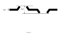
- the two-dimensional current conducting support may be a solid strip, an expanded metal or a grid, the thickness of which is generally less than or equal to 150 ⁇ m. It can also be a perforated strip. A section of a perforated strip is shown figure 1 . This section shows unperforated zones of thickness Ep1 and perforated zones whose peak-to-peak thickness is Ep2.
- the binder When the conductive support does not have a three-dimensional structure for holding the active material in the electrode, as in the case of a foam or a nickel felt, the binder must ensure during the operation of the accumulator, the cohesion of the grains of active material between them and their adhesion to the support of the electrode. Its role in the electrode is therefore essential. It must have adhesion properties vis-à-vis the active ingredient and the metal support as well as elasticity properties to withstand the deformations that occur during the manufacture of the accumulator and during its operation. cycling. The binder must also have a sufficient chemical stability with respect to the electrolyte which is strongly basic, and be resistant to electrochemical oxidation because of the oxidizing potential of the positive electrode and the oxygen generated at the end of the process.
- the oxidation of the binder in an aqueous medium results in a consumption of the hydroxyl ions of the electrolyte and the formation of carbonate ions. This leads to the degradation of the ionic conductivity of the electrolyte and the performance of the accumulator in particular at high discharge regime.
- the oxidation of the binder to the positive electrode generates in parallel a reduction reaction at the negative electrode.
- the excess negative capacity thus decreases in proportion to the amount of electrons generated by the binder oxidation reaction.
- the negative electrode When the excess of negative capacity becomes zero, the negative electrode generates charged hydrogen gas.
- the pressure in the element increases until the safety valve is opened. This results in a rapid drying of the accumulator and a strong irreversible degradation of the capacity.
- Polytetrafluoroethylene (PTFE) used as a binder in conventional foam-type positive electrodes is a stable polymer in basic and oxidation-resistant medium. But this polymer is not sufficiently adhesive and flexible to obtain a plasticized positive electrode having a satisfactory mechanical strength.
- a plasticized positive electrode comprising an elastomer which is a copolymer of ethylene and vinyl acetate (EVA).
- EVA ethylene and vinyl acetate
- An alkaline electrolyte battery which has an improved lifetime when subjected to a continuous charge current and a high temperature, that is, greater than or equal to 40 ° C.
- the fluoropolymer is selected from the group consisting of polytetrafluoroethylene (PTFE), hexafluoropropylene (HFP), a hexafluoropropylene tetrafluoroethylene (FEP) copolymer, a perfluororalkoxy polymer (PFA), and a mixture of these.
- PTFE polytetrafluoroethylene
- HFP hexafluoropropylene
- FEP hexafluoropropylene tetrafluoroethylene
- PFA perfluororalkoxy polymer
- the cellulosic polymer is selected from the group consisting of carboxymethylcellulose (CMC), hydroxypropylmethylcellulose (HPMC), hydroxypropylcellulose (HPC), hydroxyethylcellulose (HEC), and a mixture thereof. .
- the copolymer A) of tetrafluoroethylene and propylene comprises from 30 to 70% of tetrafluoroethylene units and from 30 to 70% of propylene units; the fluoropolymer B) is polytetrafluoroethylene and the cellulosic polymer C) is carboxymethylcellulose.
- 0.2 ⁇ c ⁇ 0.4 preferably 0.2 ⁇ c 0 0.3.
- the electrode comprises silane of general formula X-Si (OR) 3 ,
- R may be chosen from the group consisting of methyl, ethyl, isopropyl, cyclohexyl or phenyl groups;
- X may be selected from the group consisting of epoxy, amine, styrylamine, methacrylate, vinyl, chloroalkyl groups.
- the electrode comprises fibers, preferably of polypropylene.
- the electrochemically active material is a nickel-based hydroxide containing at least one syncrystallized cobalt hydroxide and at least one syncrystallized zinc hydroxide.
- the paste contains a compound based on yttrium, ytterbium, niobium or strontium.
- the electrode comprises neither ethylene-vinyl acetate copolymer nor copolymer of styrene and acrylate.
- the current conducting support is selected from the group consisting of a solid or perforated strip, an expanded metal and a grid.
- the invention also relates to an alkaline electrolyte accumulator comprising a positive electrode as described above.
- the Figure 1 represents a sectional view of a perforated strip.
- the unsintered positive electrode according to the invention comprises a current conducting support and a paste comprising an electrochemically active material and a binder.
- the two-dimensional current conducting support may be a solid strip, an expanded metal or a grid, the thickness of which is generally less than or equal to 150 ⁇ m. It can also be a perforated strip as described above.
- the thickness Ep1 in the non-perforated zone is generally less than or equal to 75 ⁇ m
- the peak-to-peak thickness Ep2 in the perforated zone is greater than the thickness of the non-perforated zone, and is, for example, between and 150 ⁇ m. It is considered that the thickness of a perforated strip is the peak-to-peak thickness in the perforated zone, ie Ep2.
- Ep1 is about 75 microns and Ep2 is about 110 microns.
- a perforated nickel-plated steel strip is used, characterized by a thickness of between 20 and 150 ⁇ m, a density of between 2 and 6 g / dm 2 , a daytime rate of between 20 and 80%, a diameter of perforations between 0.1 and 3 mm. More preferably, use is made of a perforated nickel-plated steel strip having a daytime of between 35 and 60%, a diameter of perforations of between 0.5 and 1.5 mm. More preferably, a perforated nickel-plated steel strip having a daytime of between 45 and 55%, a perforation diameter of between 0.9 and 1.2 mm is used.
- the electrochemically active material is a nickel-based hydroxide.
- nickel hydroxide means a nickel hydroxide, a hydroxide containing mainly nickel, but also a nickel hydroxide containing at least one syncrystallized hydroxide of a member selected from zinc (Zn), cadmium (Cd ), magnesium (Mg) and aluminum (Al), and at least one syncrystallized hydroxide of an element selected from cobalt (Co), manganese (Mn), aluminum (Al), yttrium ( Y), calcium (Ca), zirconium (Zr), copper (Cu).
- a syncrystallized hydroxide contained in the nickel hydroxide is a hydroxide forming a solid solution with nickel hydroxide, ie occupying, in a continuously variable proportion, the atomic sites defined by the crystal lattice of the nickel hydroxide.
- this hydroxide has a spheroidal shape and has a particle size of between 7 and 25 microns.
- the nickel hydroxide may preferably be covered by a cobalt hydroxide coating optionally partially oxidized, or associated with a conductive compound, consisting mainly of Co (OH) 2 .
- the binder contains no polymers other than the compounds A), B) and C) described above.
- the binder comprises only the copolymer of tetrafluoroethylene and propylene, polytetrafluoroethylene and carboxymethylcellulose.
- the polymers A), B) and C) are soluble in water or available in aqueous dispersion, which facilitates the manufacture of the electrodes by aqueous pasting on the current conducting support, followed by drying of the conductive support of current thus covered with paste.
- a silane of general formula X-Si (OR) 3 is added to the dough.
- the functional group R can be, for example, a methyl, ethyl, isopropyl, cyclohexyl or phenyl group.
- the group X may be, for example, an epoxy, amine, styrylamine, methacrylate, vinyl or chloroalkyl group.
- R is a methyl group and X is an epoxy group.
- the silane used is of the 3-glycidoxypropyltrimethoxysilane type.
- conductive or non-conductive fibers are added to the dough.
- the amount of added fiber is less than 1.5% of the mass of the dough.
- it is polymeric fibers, for example polypropylene, with a diameter of between 10 and 35 ⁇ m and a length of less than 2 mm.
- the active ingredient, any additives and the binder are introduced into the water and mixed with stirring in the paste to form a homogeneous aqueous paste which is then deposited on at least one of the faces of the current conducting support. Then, the whole is dried under air, for example at a temperature between 120 ° C and 150 ° C, preferably 130 ° C.
- the fluoropolymer B other than a copolymer of tetrafluoroethylene and propylene must be introduced separately from the other components of the binder and lastly in order to limit the interactions with the other components of the binder.
- the subject of the invention is also an alkaline battery, for example of the NiMH, NiCd or NiZn type, using a positive unsintered electrode described above and containing an electrolyte based on KOH and / or NaOH and / or LiOH and a separator for example based on untreated polyolefin fibers, or treated with acrylic acid or sulfonated or based on polyamide fibers.
- An electrochemical bundle is formed by stacking at least one positive electrode, at least one negative electrode and at least one separator.
- the electrochemical bundle may be spiraled and introduced into a cylindrical container. It can also have a flat shape and be introduced into a parallelepiped format container. The container is then filled with electrolyte.
- the accumulator may be cylindrical or prismatic, open, semi-open or sealed, for portable (safety lighting in particular) or industrial applications. It can be used in the field of automotive, space, telecommunications, rail, photovoltaic.
- the positive electrode P1 of the prior art consists of a three-dimensional current collector with a porosity greater than 95%, which is a nickel foam and a layer of material composed of the electrochemically active material (nickel-based hydroxide). in powder form and containing the following additives: cobalt and zinc), a conductor (cobalt hydroxide), a cellulosic polymer (CMC), yttrium oxide and PTFE according to the mass proportions noted below : Active ingredient 88.2% Co (OH) 2 10% PTFE 1% CMC 0.3% Y 2 O 3 0.5%
- PTFE is in the form of an aqueous dispersion containing 40% water.
- a paste is first made by mixing all the components in a solution of water. The dough is then deposited simultaneously on both sides of the current collector in a homogeneous manner. The assembly is then dried in order to remove the water, then rolled to the desired thickness and cut to obtain a positive electrode.
- the positive electrode P2 of the prior art consists of a current collector which is a nickel-plated steel perforated strip and a layer of material composed of the electrochemically active material (nickel-based hydroxide in pulverulent form and containing the following additives: cobalt and zinc), a conductor (cobalt hydroxide), a cellulosic polymer (CMC), polypropylene fibers, yttrium oxide, EVA and PTFE according to the mass proportions noted below: Active ingredient 84.75% Co (OH) 2 10% EVA 1% PTFE 2.5% CMC 0.25% Polypropylene fibers 1.0% Y 2 O 3 0.5%
- a paste is first made by mixing all the components in a solution of water.
- PTFE is introduced at the end of the preparation of the dough.
- the paste is then deposited simultaneously on both sides of the current collector homogeneously.
- the assembly is then dried in order to remove the water, then rolled to the desired thickness and cut to obtain a positive electrode.
- the positive electrode P3 outside the scope of the invention consists of a current collector which is a nickel-plated steel perforated strip and a layer of material composed of the electrochemically active material (nickel-based hydroxide in pulverulent form). and containing the following additives: cobalt and zinc), a conductor (hydroxide cobalt), polypropylene fibers, yttrium oxide, and a binder which is a mixture of a copolymer of tetrafluoroethylene and propylene (TFE / PP) and a cellulosic polymer (CMC) according to the mass proportions noted below: Active ingredient 87.25% Co (OH) 2 10% TFE / PP 1% CMC 0.25% Polypropylene fibers 1.0% Y 2 O 3 0.5%
- the copolymer of tetrafluoroethylene and propylene contains 55 mol% of tetrafluoroethylene monomers and 45 mol% of propylene monomers.
- TFE / PP is in the form of an aqueous dispersion containing 35% water.
- a paste is first made by mixing all the components in a solution of water. The paste is then deposited simultaneously on both sides of the current collector homogeneously. The assembly is then dried in order to remove the water, then rolled to the desired thickness and cut to obtain a positive electrode.
- the positive electrode P4 outside the scope of the invention consists of a current collector which is a nickel-plated steel perforated strip and a layer of material composed of the electrochemically active material (nickel-based hydroxide in pulverulent form). and containing the following additives: cobalt and zinc), a conductor (cobalt hydroxide), polypropylene fibers, yttrium oxide, and a binder which is a mixture of a copolymer of tetrafluoroethylene and propylene (TFE / PP) and a cellulosic polymer (CMC) according to the mass proportions noted below: Active ingredient 85.25% Co (OH) 2 10% TFE / PP 3% CMC 0.25% Polypropylene fibers 1.0% Y 2 O 3 0.5%
- a paste is first made by mixing all the components in a solution of water. The paste is then deposited simultaneously on both sides of the current collector homogeneously. The assembly is then dried in order to remove the water, then rolled to the desired thickness and cut to obtain a positive electrode.
- the positive electrode P5 outside the scope of the invention consists of a current collector which is a nickel-plated steel perforated strip and a layer of material composed of the electrochemically active material (powder-based nickel hydroxide). and containing the following additives: cobalt and zinc), a conductor (cobalt hydroxide), polypropylene fibers, yttrium oxide and a binder which is a mixture comprising PTFE and a cellulosic polymer (CMC) , according to the mass proportions noted below: Active ingredient 85.75% Co (OH) 2 10% PTFE 2.5% CMC 0.25% Polypropylene fibers 1.0% Y 2 O 3 0.5%
- PTFE is in the form of an aqueous dispersion containing 50% water.
- a paste is first made by mixing all the components in a solution of water. The paste is then deposited simultaneously on both sides of the current collector homogeneously. The assembly is then dried in order to remove the water, then rolled to the desired thickness and cut to obtain a positive electrode.
- the positive electrode P6 outside the scope of the invention consists of a current collector which is a nickel-plated steel perforated strip and a layer of material composed of the electrochemically active material (powder-based nickel hydroxide). and containing the following additives: cobalt and zinc), a conductor (cobalt hydroxide), polypropylene fibers, yttrium oxide, and a binder which is a mixture of a tetrafluoroethylene copolymer and of propylene (TFE / PP), PTFE and a cellulosic polymer (CMC), according to the mass proportions noted below: Active ingredient 85.65% Co (OH) 2 10% TFE / PP 0.1% PTFE 2.5% CMC 0.25% Polypropylene fibers 1.0% Y 2 O 3 0.5%
- TFE / PP is in the form of an aqueous dispersion containing 35% water.
- a paste is first made by mixing all the components in a solution of water.
- PTFE is introduced at the end of the preparation of the dough.
- the paste is then deposited simultaneously on both sides of the current collector homogeneously.
- the assembly is then dried in order to remove the water, then rolled to the desired thickness and cut to obtain a positive electrode.
- the positive electrode P7 consists of a current collector which is a nickel-plated steel perforated strip and a layer of material composed of the electrochemically active material (nickel-based hydroxide in pulverulent form and containing the following additives: cobalt and zinc), a conductor (cobalt hydroxide), polypropylene fibers, yttrium oxide, and a binder that is a blend of a copolymer of tetrafluoroethylene and propylene (TFE / PP), PTFE and a cellulosic polymer (CMC), according to the mass proportions noted below: Active ingredient 84.75% Co (OH) 2 10% TFE / PP 1% PTFE 2.5% CMC 0.25% Polypropylene fibers 1.0% Y 2 O 3 0.5%
- the electrochemically active material nickel-based hydroxide in pulverulent form and containing the following additives: cobalt and zinc), a conductor (cobalt hydroxide), polypropylene fibers,
- a paste is first made by mixing all the components in a solution of water.
- PTFE is introduced at the end of the preparation of the dough.
- the paste is then deposited simultaneously on both sides of the current collector homogeneously.
- the assembly is then dried in order to remove the water, then rolled to the desired thickness and cut to obtain a positive electrode.
- the positive electrode P8 consists of a current collector which is a nickel-plated steel perforated strip and a layer of material composed of the electrochemically active material (nickel-based hydroxide in pulverulent form and containing the following additives: cobalt and zinc), a conductor (cobalt hydroxide), polypropylene fibers, yttrium oxide, and a binder that is a blend of a copolymer of tetrafluoroethylene and propylene (TFE / PP), PTFE and a cellulosic polymer (CMC), according to the mass proportions noted below: Active ingredient 83.75% Co (OH) 2 10% TFE / PP 2% PTFE 2.5% CMC 0.25% Polypropylene fibers 1.0% Y 2 O 3 0.5%
- the electrochemically active material nickel-based hydroxide in pulverulent form and containing the following additives: cobalt and zinc), a conductor (cobalt hydroxide), polypropylene fibers,
- a paste is first made by mixing all the components in a solution of water.
- PTFE is introduced at the end of the preparation of the dough.
- the paste is then deposited simultaneously on both sides of the current collector homogeneously.
- the assembly is then dried in order to remove the water, then rolled to the desired thickness and cut to obtain a positive electrode.
- the positive electrode P9 outside the scope of the invention consists of a current collector which is a nickel-plated steel perforated strip and a layer of material composed of the electrochemically active material (powder-based nickel hydroxide). and containing the following additives: cobalt and zinc), a conductor (cobalt hydroxide), polypropylene fibers, yttrium oxide, and a binder which is a blend of a copolymer of tetrafluoroethylene and propylene (TFE / PP), PTFE and a cellulosic polymer (CMC), according to the mass proportions noted below: Active ingredient 80.75% Co (OH) 2 10% TFE / PP 5% PTFE 2.5% CMC 0.25% Polypropylene fibers 1.0% Y 2 O 3 0.5%
- a paste is first made by mixing all the components in a solution of water.
- PTFE is introduced at the end of the preparation of the dough.
- the paste is then deposited simultaneously on both sides of the current collector homogeneously.
- the assembly is then dried in order to remove the water, then rolled to the desired thickness and cut to obtain a positive electrode.
- the positive electrode P10 outside the scope of the invention consists of a current collector which is a strapping perforated nickel-plated steel and a layer of material composed of the electrochemically active material (nickel-based hydroxide in powder form and containing the following additives: cobalt and zinc), a conductor (cobalt hydroxide), fibers polypropylene, yttrium oxide, and a binder which is a mixture of a copolymer of tetrafluoroethylene and propylene (TFE / PP), PTFE and a cellulosic polymer (CMC), according to the weight proportions noted below : Active ingredient 85.75% Co (OH) 2 10% TFE / PP 2% PTFE 0.5% CMC 0.25% Polypropylene fibers 1.0% Y 2 O 3 0.5%
- a paste is first made by mixing all the components in a solution of water.
- PTFE is introduced at the end of the preparation of the dough.
- the paste is then deposited simultaneously on both sides of the current collector homogeneously.
- the assembly is then dried in order to remove the water, then rolled to the desired thickness and cut to obtain a positive electrode.
- the positive electrode P11 outside the scope of the invention consists of a current collector which is a nickel-plated steel perforated strip and a layer of material composed of the electrochemically active material (nickel-based hydroxide in pulverulent form). and containing the following additives: cobalt and zinc), a conductor (cobalt hydroxide), polypropylene fibers, yttrium oxide, and a binder which is a mixture of a copolymer of tetrafluoroethylene and propylene (TFE / PP), PTFE, and a cellulosic polymer (CMC), according to the mass proportions noted below: Active ingredient 81.25% Co (OH) 2 10% TFE / PP 2% PTFE 5% CMC 0.25% Polypropylene fibers 1.0% Y 2 O 3 0.5%
- a paste is first made by mixing all the components in a solution of water.
- PTFE is introduced at the end of the preparation of the dough.
- the paste is then deposited simultaneously on both sides of the current collector homogeneously.
- the assembly is then dried in order to remove the water, then rolled to the desired thickness and cut to obtain a positive electrode.
- the positive electrode P12 outside the scope of the invention consists of a current collector which is a nickel-plated steel perforated strip and a layer of material composed of the electrochemically active material (powder-based nickel hydroxide). and containing the following additives: cobalt and zinc), a conductor (cobalt hydroxide), a thickener (CMC), polypropylene fibers, yttrium oxide, and a binder that is a mixture a copolymer of tetrafluoroethylene and propylene (TFE / PP), PTFE and a cellulosic polymer (CMC), according to the mass proportions noted below: Active ingredient 84.95% Co (OH) 2 10% TFE / PP 1% PTFE 2.5% CMC 0.05% Polypropylene fibers 1.0% Y 2 O 3 0.5%
- a paste is first made by mixing all the components in a solution of water.
- PTFE is introduced at the end of the preparation of the dough.
- the dough is then deposited simultaneously on both faces of the current collector homogeneously.
- the assembly is then dried in order to remove the water, then rolled to the desired thickness and cut to obtain a positive electrode.
- the positive electrode P13 outside the scope of the invention consists of a current collector which is a nickel-plated steel perforated strip and a layer of material composed of the electrochemically active material (powder-based nickel hydroxide). and containing the following additives: cobalt and zinc), a conductor (cobalt hydroxide), polypropylene fibers, yttrium oxide, and a binder which is a mixture of a copolymer of tetrafluoroethylene and propylene (TFE / PP), PTFE and carboxymethylcellulose (CMC) according to the mass proportions noted below: Active ingredient 79.5% Co (OH) 2 10% TFE / PP 1% PTFE 2.5% CMC 1% Polypropylene fibers 1.0% Y 2 O 3 0.5%
- a paste is first made by mixing all the components in a solution of water.
- PTFE is introduced at the end of the preparation of the dough.
- the paste is then deposited simultaneously on both sides of the current collector homogeneously.
- the assembly is then dried in order to remove the water, then rolled to the desired thickness and cut to obtain a positive electrode.
- each electrode is weighed and then dropped from a height of 50 cm on a flat surface. The fall is repeated 10 times. Then the electrode is weighed again. The result of the test is expressed as the ratio of the initial mass minus the final mass referred to the initial mass. An electrode will be even stronger as this ratio will be low. The loss of material in the drop test must be less than 0.5% for the mechanical strength of the electrode to be acceptable.
- the results of the drop test show that the mechanical strength of the plasticized positive electrodes whose binder comprises at least CMC and TFE / PP, with a percentage of TFE / PP greater than or equal to 1% is satisfactory (P7-P13) whereas a mixture of CMC and PTFE does not make it possible to obtain a correct mechanical strength (P5).
- a mixture comprising TFE / PP, PTFE and CMC, in which TFE / PP is present in a percentage of 0.1% (P6) does not provide a correct mechanical strength.
- the mechanical strength of the electrodes is satisfactory when the binder is a mixture of TFE / PP, PTFE and CMC, with a percentage of TFE / PP of between 1 and 5% and a percentage of PTFE of between 0.5 and 2.5%. (P7-P13).
- the addition of PTFE should help to strengthen the cohesion of the coated material, which explains why the loss of material in the drop test of the P7 electrode (0.25% CMC, 1% TFE / PP, 2.5% PTFE) is 0.2% compared to 0.9% for the electrode P3 (0.25% CMC, 1% TFE / PP).
- An AA-size NiMH sealed battery whose positive electrode is the limiting electrode, and whose nominal capacity is 1100 mAh, consists of a positive electrode described above and a negative electrode of known type which possesses as electrochemically active material an intermetallic compound capable of forming a hydride in charge.
- the positive electrode is contiguous to a negative electrode from which it is isolated by a nonwoven polypropylene separator to form the electrochemical bundle.
- the thus spiraled bundle is inserted into a metal container and impregnated with an alkaline electrolyte which is an aqueous solution consisting of a mixture of potassium hydroxide 8N KOH and 0.5N lithium hydroxide LiOH.
- the composition of each of the accumulators is described in Table 4.
- Cycles I, II and III are repeated until the capacity of the accumulator in cycle II is less than or equal to 40% of the nominal capacity.
- the service life is determined by the overload time at 70 ° C when the capacity of the battery in Cycle II is less than 40% of rated capacity.
- Cycle 5 -4% -5% -7% -4% -4% -16% -5% -14% -23% -5%
- Self discharge in Cycle 7 (%) 11% 10% 10% 10% 9% 10% 11% 10% 10% 10% 10% Cycle III (% vs cycle II) after 3 sequences of 20 days of overload 11% 13% 44% 11% 12% 13% 45% 11% 11% 12% Life time (days) 340 100 300 340 320 280 320 300 280 80 * example out of the invention
- the electrical results show firstly that for plasticized electrodes having a percentage of binder greater than 6% (P9 and P11) or having a percentage of CMC lower than 0.1% (P12), the initial capacity measured under high current discharge (cycle 6) is significantly lower than that of the conventional accumulator. Indeed, it can be assumed that the conductivity of the electrode is affected when the amount of binder (non-conductive material) becomes top important. On the other hand, when the percentage of CMC is too low, it is assumed that the distribution of the cobalt compounds in the electrode is not correct, which degrades the conductivity of the electrode.
- the accumulator comprising a plasticized positive electrode of the prior art has a lifetime in permanent overload at 70 ° C of 100 days versus 340 days for the conventional accumulator (P1).
- accumulators with a plasticized positive electrode comprising a mixture of CMC and TFE / PP have a lifetime of at least 280 days (P4-P12), except when the amount of CMC is 1% (P13). ).
- P4-P12 a lifetime of at least 280 days
- the amount of CMC becomes high, it is assumed that the amount of carbonates in the accumulator increases, which promotes the development of a blocking layer on the surface of the active material of the negative electrode.
- accumulators comprising a plasticized positive electrode whose binder is a mixture of TFE / PP, PTFE and CMC such that the percentages of TFE / PP (a), PTFE (b) and CMC (c) satisfy the following relations: 0.5 ⁇ a ⁇ 4.0; 0.6 ⁇ b ⁇ 4.0; 0.1 ⁇ c ⁇ 0.9 and 1.2 ⁇ a + b + c ⁇ 6.0 have an initial capacity, a self-discharge after a long overload period and an overload life at temperature high, similar to those of the conventional accumulator (P1).
Landscapes
- Chemical & Material Sciences (AREA)
- Chemical Kinetics & Catalysis (AREA)
- Electrochemistry (AREA)
- General Chemical & Material Sciences (AREA)
- Battery Electrode And Active Subsutance (AREA)
Abstract
Une électrode positive non frittée pour accumulateur alcalin, comprenant :
- un support métallique conducteur de courant d'épaisseur inférieure ou égale à 150 microns et
- une pâte comprenant une matière électrochimiquement active à base d'hydroxyde de nickel et un liant ;
le liant comprenant :
A) au moins un copolymère de tétrafluoroéthylène et de propylène en un pourcentage massique 'a' par rapport à la masse de pâte tel que 0,5%<a<4% ;
B) au moins un polymère fluoré autre qu'un copolymère de tétrafluoroéthylène et de propylène, en un pourcentage massique 'b' par rapport à la masse de pâte tel que 0,6%<b<4%;
C) au moins un polymère cellulosique et/ou un polymère de l'acide acrylique, en un pourcentage massique 'c' par rapport à la masse de pâte tel que 0,1%<c<0,9% et 1,2%<a+b+c<6%.

a metal conductor support having a thickness of less than or equal to 150 microns and
a paste comprising an electrochemically active material based on nickel hydroxide and a binder;
the binder comprising:
A) at least one copolymer of tetrafluoroethylene and propylene in a weight percentage 'a' with respect to the dough mass such as 0.5% <a <4%;
B) at least one fluorinated polymer other than a copolymer of tetrafluoroethylene and propylene, in a weight percentage 'b' relative to the mass of dough such as 0.6% <b <4%;
C) at least one cellulosic polymer and / or a polymer of acrylic acid, in a weight percentage 'c' relative to the mass of dough such as 0.1% <c <0.9% and 1.2% <a + b + c <6%.
Description
Le domaine technique auquel se rapporte l'invention est celui des électrodes positives plastifiées pour accumulateur (générateur électrochimique) à électrolyte alcalin, par exemple de type NiCd, NiMH ou NiZn.The technical field to which the invention relates is that of positive electroplated electrodes for battery (electrochemical generator) with alkaline electrolyte, for example of NiCd, NiMH or NiZn type.
Les électrodes non frittées, dites aussi plastifiées, comprennent généralement un support conducteur de courant sur lequel on dépose par enduction une pâte comprenant une matière électrochimiquement active. Les électrodes non frittées au nickel utilisent généralement un support conducteur tridimensionnel de grande porosité (supérieure à 90%), de type mousse ou feutre de nickel. Une analyse des coûts par composant d'une électrode positive conventionnelle fait apparaître que le support de l'électrode positive, représente plus de 50% du coût de l'électrode.Unsintered electrodes, also called plasticized electrodes, generally comprise a current conducting support on which is deposited by coating a paste comprising an electrochemically active material. The unsintered nickel electrodes generally use a three-dimensional conductive support of high porosity (greater than 90%), foam type or nickel felt. A cost analysis by component of a conventional positive electrode shows that the support of the positive electrode represents more than 50% of the cost of the electrode.
Une électrode positive non frittée comportant un support conducteur de courant bon marché a été développée pour réduire le coût des accumulateurs. Cette électrode utilise un support conducteur bidimensionnel et une pâte comprenant une matière électrochimiquement active à base d'hydroxyde de nickel, un composé conducteur et un liant.A non-sintered positive electrode having a cheap current conducting medium has been developed to reduce the cost of batteries. This electrode uses a two-dimensional conductive support and a paste comprising an electrochemically active material based on nickel hydroxide, a conductive compound and a binder.
Le support conducteur de courant bidimensionnel peut être un feuillard plein, un métal déployé, une grille, dont l'épaisseur est en général inférieure ou égale à 150 µm. Il peut également être un feuillard perforé. Une coupe d'un feuillard perforé est représentée
Lorsque le support conducteur ne possède pas une structure tridimensionnelle permettant de maintenir la matière active dans l'électrode, comme dans le cas d'une mousse ou d'un feutre de nickel, le liant doit assurer durant le fonctionnement de l'accumulateur, la cohésion des grains de matière active entre eux et leur adhésion au support de l'électrode. Son rôle dans l'électrode est donc essentiel. Il doit présenter des propriétés d'adhésion vis-à-vis de la matière active et du support métallique ainsi que des propriétés d'élasticité afin de supporter les déformations qui ont lieu lors de la fabrication de l'accumulateur et lors de son fonctionnement en cyclage. Le liant doit aussi posséder une stabilité chimique suffisante vis-à-vis de l'électrolyte qui est fortement basique, et être résistant à l'oxydation électrochimique du fait du potentiel oxydant de l'électrode positive et de l'oxygène généré en fin de charge de l'électrode. L'oxydation du liant en milieu aqueux entraîne une consommation des ions hydroxyles de l'électrolyte et la formation d'ions carbonates. Cela conduit à dégrader la conductivité ionique de l'électrolyte et les performances de l'accumulateur notamment à fort régime de décharge. En outre, l'oxydation du liant à l'électrode positive génère en parallèle une réaction de réduction à l'électrode négative. La capacité négative excédentaire diminue ainsi proportionnellement à la quantité d'électrons générée par la réaction d'oxydation du liant. Lorsque l'excédent de capacité négative devient nul, l'électrode négative génère de l'hydrogène gazeux en charge. La pression dans l'élément augmente jusqu'à l'ouverture de la soupape de sécurité. Il s'ensuit un assèchement rapide de l'accumulateur et une forte dégradation irréversible de la capacité.When the conductive support does not have a three-dimensional structure for holding the active material in the electrode, as in the case of a foam or a nickel felt, the binder must ensure during the operation of the accumulator, the cohesion of the grains of active material between them and their adhesion to the support of the electrode. Its role in the electrode is therefore essential. It must have adhesion properties vis-à-vis the active ingredient and the metal support as well as elasticity properties to withstand the deformations that occur during the manufacture of the accumulator and during its operation. cycling. The binder must also have a sufficient chemical stability with respect to the electrolyte which is strongly basic, and be resistant to electrochemical oxidation because of the oxidizing potential of the positive electrode and the oxygen generated at the end of the process. charge of the electrode. The oxidation of the binder in an aqueous medium results in a consumption of the hydroxyl ions of the electrolyte and the formation of carbonate ions. This leads to the degradation of the ionic conductivity of the electrolyte and the performance of the accumulator in particular at high discharge regime. In addition, the oxidation of the binder to the positive electrode generates in parallel a reduction reaction at the negative electrode. The excess negative capacity thus decreases in proportion to the amount of electrons generated by the binder oxidation reaction. When the excess of negative capacity becomes zero, the negative electrode generates charged hydrogen gas. The pressure in the element increases until the safety valve is opened. This results in a rapid drying of the accumulator and a strong irreversible degradation of the capacity.
Le polytétrafluoroéthylène (PTFE) utilisé comme liant dans les électrodes positives conventionnelles de type mousse est un polymère stable en milieu basique et résistant à l'oxydation. Mais ce polymère n'est pas suffisamment adhésif et souple pour obtenir une électrode positive plastifiée présentant une tenue mécanique satisfaisante.Polytetrafluoroethylene (PTFE) used as a binder in conventional foam-type positive electrodes is a stable polymer in basic and oxidation-resistant medium. But this polymer is not sufficiently adhesive and flexible to obtain a plasticized positive electrode having a satisfactory mechanical strength.
De nouvelles solutions ont été développées pour résoudre le problème de la tenue mécanique de l'électrode positive non-frittée.New solutions have been developed to solve the problem of the mechanical strength of the unsintered positive electrode.
Dans le brevet
Dans la demande
On recherche un accumulateur à électrolyte alcalin qui présente une durée de vie améliorée lorsqu'il est soumis à un courant de charge permanent et à une température élevée, c'est-à-dire supérieure ou égale à 40°C.An alkaline electrolyte battery is sought which has an improved lifetime when subjected to a continuous charge current and a high temperature, that is, greater than or equal to 40 ° C.
A cet effet, l'invention a pour objet une électrode positive non frittée pour accumulateur alcalin, comprenant :
- un support métallique conducteur de courant d'épaisseur inférieure ou égale à 150 microns et
- une pâte comprenant une matière électrochimiquement active à base d'hydroxyde de nickel et un liant ;
le liant comprenant :- A) au moins un copolymère de tétrafluoroéthylène et de propylène en un pourcentage massique 'a' par rapport à la masse de pâte tel que 0,5%<a<4%;
- B) au moins un polymère fluoré autre qu'un copolymère de tétrafluoroéthylène et de propylène, en un pourcentage massique 'b' par rapport à la masse de pâte tel que 0,6%<b<4%;
- C) au moins un polymère cellulosique et/ou un polymère de l'acide acrylique, en un pourcentage massique 'c' par rapport à la masse de pâte tel que 0,1%<c<0,9%; et 1,2%<a+b+c<6%.
- a metal conductor support of current less than or equal to 150 microns thick and
- a paste comprising an electrochemically active material based on nickel hydroxide and a binder;
the binder comprising:- A) at least one copolymer of tetrafluoroethylene and propylene in a weight percentage 'a' with respect to the dough mass such as 0.5% <a <4%;
- B) at least one fluorinated polymer other than a copolymer of tetrafluoroethylene and propylene, in a weight percentage 'b' relative to the mass of dough such as 0.6% <b <4%;
- C) at least one cellulosic polymer and / or a polymer of acrylic acid, in a weight percentage 'c' with respect to the dough mass such as 0.1% <c <0.9%; and 1.2% <a + b + c <6%.
Selon un mode de réalisation, le polymère fluoré est choisi dans le groupe consistant en le polytétrafluoroéthylène (PTFE), l'hexafluoropropylène (HFP), un copolymère d'hexafluoropropylène et de tétrafluoroéthylène (FEP), un polymère perfluororalkoxy (PFA), et un mélange de ceux-ci.According to one embodiment, the fluoropolymer is selected from the group consisting of polytetrafluoroethylene (PTFE), hexafluoropropylene (HFP), a hexafluoropropylene tetrafluoroethylene (FEP) copolymer, a perfluororalkoxy polymer (PFA), and a mixture of these.
Selon un mode de réalisation, le polymère cellulosique est choisi dans le groupe consistant en la carboxyméthylcellulose (CMC), l'hydroxypropylméthylcellulose (HPMC), l'hydroxypropylcellulose (HPC), l'hydroxyéthylcellulose (HEC), et un mélange de ceux-ci.According to one embodiment, the cellulosic polymer is selected from the group consisting of carboxymethylcellulose (CMC), hydroxypropylmethylcellulose (HPMC), hydroxypropylcellulose (HPC), hydroxyethylcellulose (HEC), and a mixture thereof. .
Selon un mode de réalisation, le copolymère A) de tétrafluoroéthylène et de propylène comprend de 30 à 70% d'unités tétrafluoroéthylène et de 30 à 70% d'unités propylène; le polymère fluoré B) est le polytétrafluoroéthylène et le polymère cellulosique C) est la carboxyméthylcellulose.According to one embodiment, the copolymer A) of tetrafluoroethylene and propylene comprises from 30 to 70% of tetrafluoroethylene units and from 30 to 70% of propylene units; the fluoropolymer B) is polytetrafluoroethylene and the cellulosic polymer C) is carboxymethylcellulose.
Selon un mode de réalisation, 0,8<a<3, de préférence 1≤a≤2.According to one embodiment, 0.8 <a <3, preferably 1≤a≤2.
Selon un mode de réalisation, 1<b<3, de préférence 2<b<3.According to one embodiment, 1 <b <3, preferably 2 <b <3.
Selon un mode de réalisation, 0,2<c<0,4, de préférence 0,2<c≤0,3.According to one embodiment, 0.2 <c <0.4, preferably 0.2 <c 0 0.3.
Selon un mode de réalisation, 3≤a+b+c≤5.According to one embodiment, 3 a a + b + c 5 5.
Selon un mode de réalisation, l'électrode comprend du silane de formule générale X-Si(OR)3, R pouvant être choisi dans le groupe consistant en les groupements méthyle, éthyle, isopropyle, cyclohexyle ou phényle ; X pouvant être choisi dans le groupe consistant en les groupements époxy, amine, styrylamine, méthacrylate, vinyle, chloroalkyle.According to one embodiment, the electrode comprises silane of general formula X-Si (OR) 3 , R may be chosen from the group consisting of methyl, ethyl, isopropyl, cyclohexyl or phenyl groups; X may be selected from the group consisting of epoxy, amine, styrylamine, methacrylate, vinyl, chloroalkyl groups.
Selon un mode de réalisation, l'électrode comprend des fibres, de préférence en polypropylène.According to one embodiment, the electrode comprises fibers, preferably of polypropylene.
Selon un mode de réalisation, la matière électrochimiquement active est un hydroxyde à base de nickel contenant au moins un hydroxyde syncristallisé de cobalt et au moins un hydroxyde syncristallisé de zinc.In one embodiment, the electrochemically active material is a nickel-based hydroxide containing at least one syncrystallized cobalt hydroxide and at least one syncrystallized zinc hydroxide.
Selon un mode de réalisation, la pâte contient un composé à base d'yttrium, d'ytterbium, de niobium ou de strontium.According to one embodiment, the paste contains a compound based on yttrium, ytterbium, niobium or strontium.
Selon un mode de réalisation, l'électrode ne comprend ni copolymère d'éthylène et d'acétate de vinyle, ni copolymère de styrène et d'acrylate.According to one embodiment, the electrode comprises neither ethylene-vinyl acetate copolymer nor copolymer of styrene and acrylate.
Selon un mode de réalisation, le support conducteur de courant est choisi dans le groupe consistant en un feuillard plein ou perforé, un métal déployé et une grille.According to one embodiment, the current conducting support is selected from the group consisting of a solid or perforated strip, an expanded metal and a grid.
L'invention a également pour objet un accumulateur à électrolyte alcalin comprenant une électrode positive telle que décrite ci-avant.The invention also relates to an alkaline electrolyte accumulator comprising a positive electrode as described above.
La
L'électrode positive non frittée selon l'invention comprend un support conducteur de courant et une pâte comprenant une matière électrochimiquement active et un liant.The unsintered positive electrode according to the invention comprises a current conducting support and a paste comprising an electrochemically active material and a binder.
Le support conducteur de courant bidimensionnel peut être un feuillard plein, un métal déployé, une grille, dont l'épaisseur est en général inférieure ou égale à 150 µm. Il peut également être un feuillard perforé tel que décrit ci-avant. L'épaisseur Ep1 dans la zone non perforée est en général inférieure ou égale à 75 µm, et l'épaisseur crête à crête Ep2 dans la zone perforée est supérieure à l'épaisseur de la zone non perforée, et est par exemple comprise entre 75 et 150 µm. On considère que l'épaisseur d'un feuillard perforé est l'épaisseur crête à crête dans la zone perforée, soit Ep2. Dans un mode de réalisation préféré, Ep1 vaut environ 75 µm et Ep2 vaut environ 110 µm.The two-dimensional current conducting support may be a solid strip, an expanded metal or a grid, the thickness of which is generally less than or equal to 150 μm. It can also be a perforated strip as described above. The thickness Ep1 in the non-perforated zone is generally less than or equal to 75 μm, and the peak-to-peak thickness Ep2 in the perforated zone is greater than the thickness of the non-perforated zone, and is, for example, between and 150 μm. It is considered that the thickness of a perforated strip is the peak-to-peak thickness in the perforated zone, ie Ep2. In a preferred embodiment, Ep1 is about 75 microns and Ep2 is about 110 microns.
De préférence, on utilise un feuillard en acier nickelé perforé, caractérisé par une épaisseur comprise entre 20 et 150 µm, une masse surfacique comprise entre 2 et 6 g/dm2, un taux de jour compris entre 20 et 80 %, un diamètre de perforations compris entre 0,1 et 3 mm. De préférence encore, on utilise un feuillard en acier nickelé perforé présentant un taux de jour compris entre 35 et 60 %, un diamètre de perforations compris entre 0,5 et 1,5 mm. De préférence encore, on utilise un feuillard en acier nickelé perforé présentant un taux de jour compris entre 45 et 55 %, un diamètre de perforations compris entre 0,9 et 1,2 mm.Preferably, a perforated nickel-plated steel strip is used, characterized by a thickness of between 20 and 150 μm, a density of between 2 and 6 g / dm 2 , a daytime rate of between 20 and 80%, a diameter of perforations between 0.1 and 3 mm. More preferably, use is made of a perforated nickel-plated steel strip having a daytime of between 35 and 60%, a diameter of perforations of between 0.5 and 1.5 mm. More preferably, a perforated nickel-plated steel strip having a daytime of between 45 and 55%, a perforation diameter of between 0.9 and 1.2 mm is used.
La matière électrochimiquement active est un hydroxyde à base de nickel. On entend par "hydroxyde à base de nickel" un hydroxyde de nickel, un hydroxyde contenant principalement du nickel, mais également un hydroxyde de nickel contenant au moins un hydroxyde syncristallisé d'un élément choisi parmi le zinc (Zn), le cadmium (Cd), le magnésium (Mg) et l'aluminium (Al), et au moins un hydroxyde syncristallisé d'un élément choisi parmi le cobalt (Co), le manganèse (Mn), l'aluminium (Al), l'yttrium (Y), le calcium (Ca), le zirconium (Zr), le cuivre (Cu). Un hydroxyde syncristallisé contenu dans l'hydroxyde de nickel est un hydroxyde formant une solution solide avec l'hydroxyde de nickel, i.e. occupant, en proportion continûment variable, les sites atomiques définis par le réseau cristallin de l'hydroxyde de nickel. De préférence cet hydroxyde possède une forme sphéroïdale et présente une granulométrie comprise entre 7 et 25 µm. L'hydroxyde de nickel peut être de façon préférentielle recouvert par un revêtement à base d'hydroxyde de cobalt éventuellement partiellement oxydé, ou associé à un composé conducteur, constitué principalement de Co(OH)2.The electrochemically active material is a nickel-based hydroxide. The term "nickel hydroxide" means a nickel hydroxide, a hydroxide containing mainly nickel, but also a nickel hydroxide containing at least one syncrystallized hydroxide of a member selected from zinc (Zn), cadmium (Cd ), magnesium (Mg) and aluminum (Al), and at least one syncrystallized hydroxide of an element selected from cobalt (Co), manganese (Mn), aluminum (Al), yttrium ( Y), calcium (Ca), zirconium (Zr), copper (Cu). A syncrystallized hydroxide contained in the nickel hydroxide is a hydroxide forming a solid solution with nickel hydroxide, ie occupying, in a continuously variable proportion, the atomic sites defined by the crystal lattice of the nickel hydroxide. Preferably this hydroxide has a spheroidal shape and has a particle size of between 7 and 25 microns. The nickel hydroxide may preferably be covered by a cobalt hydroxide coating optionally partially oxidized, or associated with a conductive compound, consisting mainly of Co (OH) 2 .
D'autres composés tels que Co, CoO, LiCoO2, poudres métalliques, carbones, ZnO, Y2O3, Yb2O3, Nb2O5, SrSO4, Sr(OH)2 peuvent être ajoutés à la matière active.Other compounds such as Co, CoO, LiCoO 2 , metal powders, carbons, ZnO, Y 2 O 3 , Yb 2 O 3 , Nb 2 O 5 , SrSO 4 , Sr (OH) 2 may be added to the active ingredient .
Le liant comprend:
- A) au moins un copolymère de tétrafluoroéthylène et de propylène. Dans un mode préféré de réalisation, le copolymère A) de tétrafluoroéthylène et de propylène comprend de 30 à 70% d'unités tétrafluoroéthylène et de 30 à 70% d'unités propylène. Dans un mode préféré de réalisation, sa masse moléculaire est comprise entre 2000 et 1 000 000 g/mole.
- B) au moins un polymère fluoré autre qu'un copolymère de tétrafluoroéthylène et de propylène. De préférence, le polymère fluoré B est choisi dans le groupe consistant en le polytétrafluoroéthylène (PTFE), l'hexafluoropropylène (HFP), un copolymère d'hexafluoropropylène et de tétrafluoroéthylène (FEP), un polymère perfluororalkoxy (PFA), et un mélange de ceux-ci. De préférence, le polymère fluoré est PTFE.
- C) au moins un polymère cellulosique et/ou un polymère de l'acide acrylique. Le polymère cellulosique peut être choisi dans le groupe consistant en la carboxyméthylcellulose (CMC), l'hydroxypropylméthylcellulose (HPMC), l'hydroxypropylcellulose (HPC), l'hydroxyéthylcellulose (HEC) et un mélange de ceux-ci. De préférence, le polymère cellulosique est la carboxyméthylcellulose.
- A) at least one copolymer of tetrafluoroethylene and propylene. In a preferred embodiment, the copolymer A) of tetrafluoroethylene and propylene comprises from 30 to 70% of tetrafluoroethylene units and from 30 to 70% of propylene units. In a preferred embodiment, its molecular weight is between 2,000 and 1,000,000 g / mol.
- B) at least one fluorinated polymer other than a copolymer of tetrafluoroethylene and propylene. Preferably, the fluoropolymer B is selected from the group consisting of polytetrafluoroethylene (PTFE), hexafluoropropylene (HFP), a copolymer of hexafluoropropylene and tetrafluoroethylene (FEP), a perfluororalkoxy polymer (PFA), and a mixture of them. Preferably, the fluoropolymer is PTFE.
- C) at least one cellulosic polymer and / or a polymer of acrylic acid. The cellulosic polymer may be selected from the group consisting of carboxymethylcellulose (CMC), hydroxypropylmethylcellulose (HPMC), hydroxypropylcellulose (HPC), hydroxyethylcellulose (HEC) and a mixture thereof. Preferably, the cellulosic polymer is carboxymethylcellulose.
Dans un mode de réalisation, le liant ne contient pas d'autres polymères que les composés A), B) et C) décrits ci-dessus. Dans un mode de réalisation préféré, le liant ne comprend que le copolymère de tétrafluoroéthylène et de propylène, du polytétrafluoroéthylène et de la carboxyméthylcellulose.In one embodiment, the binder contains no polymers other than the compounds A), B) and C) described above. In a preferred embodiment, the binder comprises only the copolymer of tetrafluoroethylene and propylene, polytetrafluoroethylene and carboxymethylcellulose.
Les polymères A), B) et C) sont solubles dans l'eau ou disponibles en dispersion aqueuse, ce qui facilite la fabrication des électrodes par empâtage par voie aqueuse sur le support conducteur de courant, suivi d'un séchage du support conducteur de courant ainsi recouvert de pâte.The polymers A), B) and C) are soluble in water or available in aqueous dispersion, which facilitates the manufacture of the electrodes by aqueous pasting on the current conducting support, followed by drying of the conductive support of current thus covered with paste.
Le pourcentage en masse de chacun des polymères par rapport à la masse totale de pâte sèche sur le support conducteur de courant est noté 'a' pour le polymère A, 'b' pour le polymère B et 'c' pour le polymère C avec :
- 0,5<a<4, de préférence 0,8<a<3,0, de préférence encore 1≤a≤2. Dans un mode de réalisation, 1≤a<2.
- 0,6<b<4, de préférence 1<b<3, de préférence encore 2≤b<3 ; 0,1<c<0,9, de préférence 0,2<c<0,4, de préférence encore 0,2<c≤0,3
- 1,2<a+b+c<6,0, de préférence 3≤a+b+c≤5.
- 0.5 <a <4, preferably 0.8 <a <3.0, more preferably 1≤a≤2. In one embodiment, 1≤a <2.
- 0.6 <b <4, preferably 1 <b <3, more preferably 2≤b <3; 0.1 <c <0.9, preferably 0.2 <c <0.4, more preferably 0.2 <c≤0.3
- 1.2 <a + b + c <6.0, preferably 3≤a + b + c≤5.
Les pourcentages en masse a, b et c de chacun des polymères A, B et C sont donnés par rapport à la masse totale de pâte enduite sur le collecteur de courant, après séchage de l'électrode.The percentages by weight a, b and c of each of the polymers A, B and C are given with respect to the total mass of paste coated on the current collector, after drying of the electrode.
Selon un mode de réalisation, un silane de formule générale X-Si(OR)3 est ajouté à la pâte. Le groupement fonctionnel R peut être par exemple un groupement méthyle, éthyle, isopropyle, cyclohexyle ou phényle. Le groupement X peut être par exemple un groupement époxy, amine, styrylamine, méthacrylate, vinyle, chloroalkyle. De préférence, R est un groupement méthyle et X est un groupement époxy. De préférence encore, le silane utilisé est de type 3-glycidoxypropyltrimethoxy-silane.According to one embodiment, a silane of general formula X-Si (OR) 3 is added to the dough. The functional group R can be, for example, a methyl, ethyl, isopropyl, cyclohexyl or phenyl group. The group X may be, for example, an epoxy, amine, styrylamine, methacrylate, vinyl or chloroalkyl group. Preferably, R is a methyl group and X is an epoxy group. More preferably, the silane used is of the 3-glycidoxypropyltrimethoxysilane type.
Selon un mode de réalisation, des fibres conductrices ou non conductrices sont ajoutées à la pâte. De préférence, la quantité de fibres ajoutées est inférieure à 1,5% de la masse de la pâte. De préférence, il s'agit de fibres polymères, de polypropylène par exemple, de diamètre compris entre 10 et 35 µm et de longueur inférieure à 2 mm.According to one embodiment, conductive or non-conductive fibers are added to the dough. Preferably, the amount of added fiber is less than 1.5% of the mass of the dough. Preferably, it is polymeric fibers, for example polypropylene, with a diameter of between 10 and 35 μm and a length of less than 2 mm.
La matière active, les éventuels additifs et le liant sont introduits dans l'eau et mélangés sous agitation à la pâte pour former une pâte aqueuse homogène qui est ensuite déposée sur au moins une des faces du support conducteur de courant. Puis, l'ensemble est séché sous air, par exemple à une température comprise entre 120°C et 150°C, de préférence 130°C. Pour obtenir une électrode positive plastifiée présentant une bonne adhésion entre la matière et le collecteur de courant, le polymère fluoré B autre qu'un copolymère de tétrafluoroéthylène et de propylène doit être introduit séparément des autres composants du liant et en dernier afin de limiter les interactions avec les autres composants du liant.The active ingredient, any additives and the binder are introduced into the water and mixed with stirring in the paste to form a homogeneous aqueous paste which is then deposited on at least one of the faces of the current conducting support. Then, the whole is dried under air, for example at a temperature between 120 ° C and 150 ° C, preferably 130 ° C. To obtain a plasticized positive electrode having a good adhesion between the material and the current collector, the fluoropolymer B other than a copolymer of tetrafluoroethylene and propylene must be introduced separately from the other components of the binder and lastly in order to limit the interactions with the other components of the binder.
L'invention a également pour objet un accumulateur alcalin par exemple de type NiMH, NiCd ou NiZn, utilisant une électrode positive non frittée décrite ci-dessus et contenant un électrolyte à base de KOH et/ou NaOH et/ou LiOH et un séparateur par exemple à base de fibres de polyoléfines non traitées, ou traitées par de l'acide acrylique ou sulfonées ou à base de fibres de polyamide.The subject of the invention is also an alkaline battery, for example of the NiMH, NiCd or NiZn type, using a positive unsintered electrode described above and containing an electrolyte based on KOH and / or NaOH and / or LiOH and a separator for example based on untreated polyolefin fibers, or treated with acrylic acid or sulfonated or based on polyamide fibers.
On forme un faisceau électrochimique en empilant au moins une électrode positive, au moins une électrode négative et au moins un séparateur. Le faisceau électrochimique peut être spiralé et introduit dans un conteneur de format cylindrique. Il peut également avoir une forme plane et être introduit dans un conteneur de format parallélépipédique. Le conteneur est ensuite rempli d'électrolyte.An electrochemical bundle is formed by stacking at least one positive electrode, at least one negative electrode and at least one separator. The electrochemical bundle may be spiraled and introduced into a cylindrical container. It can also have a flat shape and be introduced into a parallelepiped format container. The container is then filled with electrolyte.
L'accumulateur peut être de type cylindrique ou prismatique, ouvert, semi-ouvert ou étanche, pour des applications portables (éclairage de sécurité notamment) ou industrielles. Il peut être utilisé dans le domaine de l'automobile, du spatial, des télécommunications, ferroviaire, photovoltaïque.The accumulator may be cylindrical or prismatic, open, semi-open or sealed, for portable (safety lighting in particular) or industrial applications. It can be used in the field of automotive, space, telecommunications, rail, photovoltaic.
L'électrode positive P1 de l'art antérieur est constituée d'un collecteur de courant tridimensionnel de porosité supérieure à 95% qui est une mousse de nickel et d'une couche de matière composée de la matière électrochimiquement active (hydroxyde à base de nickel sous forme pulvérulente et contenant les additifs suivants : cobalt et zinc), d'un conducteur (hydroxyde de cobalt), d'un polymère cellulosique (CMC), d'oxyde d'yttrium et de PTFE selon les proportions massiques notées ci-dessous :
Le PTFE se présente sous la forme d'une dispersion aqueuse contenant 40% d'eau. Pour réaliser l'électrode, une pâte est tout d'abord fabriquée en mélangeant tous les composants dans une solution d'eau. La pâte est ensuite déposée simultanément sur les deux faces du collecteur de courant de manière homogène. L'ensemble est ensuite séché afin d'en éliminer l'eau, puis laminé à l'épaisseur désirée et découpée pour obtenir une électrode positive.PTFE is in the form of an aqueous dispersion containing 40% water. To make the electrode, a paste is first made by mixing all the components in a solution of water. The dough is then deposited simultaneously on both sides of the current collector in a homogeneous manner. The assembly is then dried in order to remove the water, then rolled to the desired thickness and cut to obtain a positive electrode.
L'électrode positive P2 de l'art antérieur est constituée d'un collecteur de courant qui est un feuillard perforé en acier nickelé et d'une couche de matière composée de la matière électrochimiquement active (hydroxyde à base de nickel sous forme pulvérulente et contenant les additifs suivants : cobalt et zinc), d'un conducteur (hydroxyde de cobalt), d'un polymère cellulosique (CMC), de fibres en polypropylène, d'oxyde d'yttrium, d'EVA et de PTFE selon les proportions massiques notées ci-dessous :
Pour réaliser l'électrode, une pâte est tout d'abord fabriquée en mélangeant tous les composants dans une solution d'eau. Le PTFE est introduit à la fin de la préparation de la pâte. La pâte est ensuite déposée simultanément sur les deux faces du collecteur courant de manière homogène. L'ensemble est ensuite séché afin d'en éliminer l'eau, puis laminé à l'épaisseur désirée et découpée pour obtenir une électrode positive.To make the electrode, a paste is first made by mixing all the components in a solution of water. PTFE is introduced at the end of the preparation of the dough. The paste is then deposited simultaneously on both sides of the current collector homogeneously. The assembly is then dried in order to remove the water, then rolled to the desired thickness and cut to obtain a positive electrode.
L'électrode positive P3 hors du domaine de l'invention est constituée d'un collecteur de courant qui est un feuillard perforé en acier nickelé et d'une couche de matière composée de la matière électrochimiquement active (hydroxyde à base de nickel sous forme pulvérulente et contenant les additifs suivants : cobalt et zinc), d'un conducteur (hydroxyde de cobalt), de fibres en polypropylène, d'oxyde d'yttrium, et d'un liant qui est mélange d'un copolymère de tétrafluoroéthylène et de propylène (TFE/PP) et d'un polymère cellulosique (CMC) selon les proportions massiques notées ci-dessous :
Le copolymère de tétrafluoroéthylène et de propylène (TFE/PP) contient 55% en mole de monomères de tétrafluoroéthylène et 45% en mole de monomères de propylène.The copolymer of tetrafluoroethylene and propylene (TFE / PP) contains 55 mol% of tetrafluoroethylene monomers and 45 mol% of propylene monomers.
Le TFE/PP se présente sous la forme d'une dispersion aqueuse contenant 35% d'eau. Pour réaliser l'électrode, une pâte est tout d'abord fabriquée en mélangeant tous les composants dans une solution d'eau. La pâte est ensuite déposée simultanément sur les deux faces du collecteur de courant de manière homogène. L'ensemble est ensuite séché afin d'en éliminer l'eau, puis laminé à l'épaisseur désirée et découpée pour obtenir une électrode positive.TFE / PP is in the form of an aqueous dispersion containing 35% water. To make the electrode, a paste is first made by mixing all the components in a solution of water. The paste is then deposited simultaneously on both sides of the current collector homogeneously. The assembly is then dried in order to remove the water, then rolled to the desired thickness and cut to obtain a positive electrode.
L'électrode positive P4 hors du domaine de l'invention est constituée d'un collecteur de courant qui est un feuillard perforé en acier nickelé et d'une couche de matière composée de la matière électrochimiquement active (hydroxyde à base de nickel sous forme pulvérulente et contenant les additifs suivants : cobalt et zinc), d'un conducteur (hydroxyde de cobalt), de fibres en polypropylène, d'oxyde d'yttrium, et d'un liant qui est un mélange d'un copolymère de tétrafluoroéthylène et de propylène (TFE/PP) et d'un polymère cellulosique (CMC) selon les proportions massiques notées ci-dessous :
Pour réaliser l'électrode, une pâte est tout d'abord fabriquée en mélangeant tous les composants dans une solution d'eau. La pâte est ensuite déposée simultanément sur les deux faces du collecteur de courant de manière homogène. L'ensemble est ensuite séché afin d'en éliminer l'eau, puis laminé à l'épaisseur désirée et découpée pour obtenir une électrode positive.To make the electrode, a paste is first made by mixing all the components in a solution of water. The paste is then deposited simultaneously on both sides of the current collector homogeneously. The assembly is then dried in order to remove the water, then rolled to the desired thickness and cut to obtain a positive electrode.
L'électrode positive P5 hors du domaine de l'invention est constituée d'un collecteur de courant qui est un feuillard perforé en acier nickelé et d'une couche de matière composée de la matière électrochimiquement active (hydroxyde à base de nickel sous forme pulvérulente et contenant les additifs suivants : cobalt et zinc), d'un conducteur (hydroxyde de cobalt), de fibres en polypropylène, d'oxyde d'yttrium et d'un liant qui est un mélange comprenant PTFE et un polymère cellulosique (CMC), selon les proportions massiques notées ci-dessous :
Le PTFE se présente sous la forme d'une dispersion aqueuse contenant 50% d'eau. Pour réaliser l'électrode, une pâte est tout d'abord fabriquée en mélangeant tous les composants dans une solution d'eau. La pâte est ensuite déposée simultanément sur les deux faces du collecteur de courant de manière homogène. L'ensemble est ensuite séché afin d'en éliminer l'eau, puis laminé à l'épaisseur désirée et découpée pour obtenir une électrode positive.PTFE is in the form of an aqueous dispersion containing 50% water. To make the electrode, a paste is first made by mixing all the components in a solution of water. The paste is then deposited simultaneously on both sides of the current collector homogeneously. The assembly is then dried in order to remove the water, then rolled to the desired thickness and cut to obtain a positive electrode.
L'électrode positive P6 hors du domaine de l'invention est constituée d'un collecteur de courant qui est un feuillard perforé en acier nickelé et d'une couche de matière composée de la matière électrochimiquement active (hydroxyde à base de nickel sous forme pulvérulente et contenant les additifs suivants : cobalt et zinc), d'un conducteur (hydroxyde de cobalt), de fibres en polypropylène, d'oxyde d'yttrium, et d'un liant qui est un mélange constitué d'un copolymère de tétrafluoroéthylène et de propylène (TFE/PP), de PTFE et d'un polymère cellulosique (CMC), selon les proportions massiques notées ci-dessous :
Le TFE/PP se présente sous la forme d'une dispersion aqueuse contenant 35% d'eau. Pour réaliser l'électrode, une pâte est tout d'abord fabriquée en mélangeant tous les composants dans une solution d'eau. Le PTFE est introduit à la fin de la préparation de la pâte. La pâte est ensuite déposée simultanément sur les deux faces du collecteur de courant de manière homogène. L'ensemble est ensuite séché afin d'en éliminer l'eau, puis laminé à l'épaisseur désirée et découpée pour obtenir une électrode positive.TFE / PP is in the form of an aqueous dispersion containing 35% water. To make the electrode, a paste is first made by mixing all the components in a solution of water. PTFE is introduced at the end of the preparation of the dough. The paste is then deposited simultaneously on both sides of the current collector homogeneously. The assembly is then dried in order to remove the water, then rolled to the desired thickness and cut to obtain a positive electrode.
L'électrode positive P7 selon l'invention est constituée d'un collecteur de courant qui est un feuillard perforé en acier nickelé et d'une couche de matière composée de la matière électrochimiquement active (hydroxyde à base de nickel sous forme pulvérulente et contenant les additifs suivants : cobalt et zinc), d'un conducteur (hydroxyde de cobalt), de fibres en polypropylène, d'oxyde d'yttrium, et d'un liant qui est un mélange d'un copolymère de tétrafluoroéthylène et de propylène (TFE/PP), de PTFE et d'un polymère cellulosique (CMC), selon les proportions massiques notées ci-dessous :
Pour réaliser l'électrode, une pâte est tout d'abord fabriquée en mélangeant tous les composants dans une solution d'eau. Le PTFE est introduit à la fin de la préparation de la pâte. La pâte est ensuite déposée simultanément sur les deux faces du collecteur de courant de manière homogène. L'ensemble est ensuite séché afin d'en éliminer l'eau, puis laminé à l'épaisseur désirée et découpée pour obtenir une électrode positive.To make the electrode, a paste is first made by mixing all the components in a solution of water. PTFE is introduced at the end of the preparation of the dough. The paste is then deposited simultaneously on both sides of the current collector homogeneously. The assembly is then dried in order to remove the water, then rolled to the desired thickness and cut to obtain a positive electrode.
L'électrode positive P8 selon l'invention est constituée d'un collecteur de courant qui est un feuillard perforé en acier nickelé et d'une couche de matière composée de la matière électrochimiquement active (hydroxyde à base de nickel sous forme pulvérulente et contenant les additifs suivants : cobalt et zinc), d'un conducteur (hydroxyde de cobalt), de fibres en polypropylène, d'oxyde d'yttrium, et d'un liant qui est un mélange d'un copolymère de tétrafluoroéthylène et de propylène (TFE/PP), de PTFE et d'un polymère cellulosique (CMC), selon les proportions massiques notées ci-dessous :
Pour réaliser l'électrode, une pâte est tout d'abord fabriquée en mélangeant tous les composants dans une solution d'eau. Le PTFE est introduit à la fin de la préparation de la pâte. La pâte est ensuite déposée simultanément sur les deux faces du collecteur de courant de manière homogène. L'ensemble est ensuite séché afin d'en éliminer l'eau, puis laminé à l'épaisseur désirée et découpée pour obtenir une électrode positive.To make the electrode, a paste is first made by mixing all the components in a solution of water. PTFE is introduced at the end of the preparation of the dough. The paste is then deposited simultaneously on both sides of the current collector homogeneously. The assembly is then dried in order to remove the water, then rolled to the desired thickness and cut to obtain a positive electrode.
L'électrode positive P9 hors du domaine de l'invention est constituée d'un collecteur de courant qui est un feuillard perforé en acier nickelé et d'une couche de matière composée de la matière électrochimiquement active (hydroxyde à base de nickel sous forme pulvérulente et contenant les additifs suivants : cobalt et zinc), d'un conducteur (hydroxyde de cobalt), de fibres en polypropylène, d'oxyde d'yttrium, et d'un liant qui est une mélange d'un copolymère de tétrafluoroéthylène et de propylène (TFE/PP), de PTFE et d'un polymère cellulosique (CMC), selon les proportions massiques notées ci-dessous :
Pour réaliser l'électrode, une pâte est tout d'abord fabriquée en mélangeant tous les composants dans une solution d'eau. Le PTFE est introduit à la fin de la préparation de la pâte. La pâte est ensuite déposée simultanément sur les deux faces du collecteur de courant de manière homogène. L'ensemble est ensuite séché afin d'en éliminer l'eau, puis laminé à l'épaisseur désirée et découpée pour obtenir une électrode positive.To make the electrode, a paste is first made by mixing all the components in a solution of water. PTFE is introduced at the end of the preparation of the dough. The paste is then deposited simultaneously on both sides of the current collector homogeneously. The assembly is then dried in order to remove the water, then rolled to the desired thickness and cut to obtain a positive electrode.
L'électrode positive P10 hors du domaine de l'invention est constituée d'un collecteur de courant qui est un feuillard perforé en acier nickelé et d'une couche de matière composée de la matière électrochimiquement active (hydroxyde à base de nickel sous forme pulvérulente et contenant les additifs suivants : cobalt et zinc), d'un conducteur (hydroxyde de cobalt), de fibres en polypropylène, d'oxyde d'yttrium, et d'un liant qui est un mélange d'un copolymère de tétrafluoroéthylène et de propylène (TFE/PP), de PTFE et d'un polymère cellulosique (CMC), selon les proportions massiques notées ci-dessous :
Pour réaliser l'électrode, une pâte est tout d'abord fabriquée en mélangeant tous les composants dans une solution d'eau. Le PTFE est introduit à la fin de la préparation de la pâte. La pâte est ensuite déposée simultanément sur les deux faces du collecteur de courant de manière homogène. L'ensemble est ensuite séché afin d'en éliminer l'eau, puis laminé à l'épaisseur désirée et découpée pour obtenir une électrode positive.To make the electrode, a paste is first made by mixing all the components in a solution of water. PTFE is introduced at the end of the preparation of the dough. The paste is then deposited simultaneously on both sides of the current collector homogeneously. The assembly is then dried in order to remove the water, then rolled to the desired thickness and cut to obtain a positive electrode.
L'électrode positive P11 hors du domaine de l'invention est constituée d'un collecteur de courant qui est un feuillard perforé en acier nickelé et d'une couche de matière composée de la matière électrochimiquement active (hydroxyde à base de nickel sous forme pulvérulente et contenant les additifs suivants : cobalt et zinc), d'un conducteur (hydroxyde de cobalt), de fibres en polypropylène, d'oxyde d'yttrium, et d'un liant qui est un mélange d'un copolymère de tétrafluoroéthylène et de propylène (TFE/PP), de PTFE, et d'un polymère cellulosique (CMC), selon les proportions massiques notées ci-dessous :
Pour réaliser l'électrode, une pâte est tout d'abord fabriquée en mélangeant tous les composants dans une solution d'eau. Le PTFE est introduit à la fin de la préparation de la pâte. La pâte est ensuite déposée simultanément sur les deux faces du collecteur de courant de manière homogène. L'ensemble est ensuite séché afin d'en éliminer l'eau, puis laminé à l'épaisseur désirée et découpée pour obtenir une électrode positive.To make the electrode, a paste is first made by mixing all the components in a solution of water. PTFE is introduced at the end of the preparation of the dough. The paste is then deposited simultaneously on both sides of the current collector homogeneously. The assembly is then dried in order to remove the water, then rolled to the desired thickness and cut to obtain a positive electrode.
L'électrode positive P12 hors du domaine de l'invention est constituée d'un collecteur de courant qui est un feuillard perforé en acier nickelé et d'une couche de matière composée de la matière électrochimiquement active (hydroxyde à base de nickel sous forme pulvérulente et contenant les additifs suivants : cobalt et zinc), d'un conducteur (hydroxyde de cobalt), d'un épaississant (CMC), de fibres en polypropylène, d'oxyde d'yttrium, et d'un liant qui est un mélange d'un copolymère de tétrafluoroéthylène et de propylène (TFE/PP), de PTFE et d'un polymère cellulosique (CMC), selon les proportions massiques notées ci-dessous :
Pour réaliser l'électrode, une pâte est tout d'abord fabriquée en mélangeant tous les composants dans une solution d'eau. Le PTFE est introduit à la fin de la préparation de la pâte. La pâte est ensuite déposée simultanément sur les deux faces du collecteur de courant de manière homogène. L'ensemble est ensuite séché afin d'en éliminer l'eau, puis laminé à l'épaisseur désirée et découpée pour obtenir une électrode positive.To make the electrode, a paste is first made by mixing all the components in a solution of water. PTFE is introduced at the end of the preparation of the dough. The dough is then deposited simultaneously on both faces of the current collector homogeneously. The assembly is then dried in order to remove the water, then rolled to the desired thickness and cut to obtain a positive electrode.
L'électrode positive P13 hors du domaine de l'invention est constituée d'un collecteur de courant qui est un feuillard perforé en acier nickelé et d'une couche de matière composée de la matière électrochimiquement active (hydroxyde à base de nickel sous forme pulvérulente et contenant les additifs suivants : cobalt et zinc), d'un conducteur (hydroxyde de cobalt), de fibres en polypropylène, d'oxyde d'yttrium, et d'un liant qui est un mélange d'un copolymère de tétrafluoroéthylène et de propylène (TFE/PP), de PTFE et de carboxyméthylcellulose (CMC) selon les proportions massiques notées ci-dessous :
Pour réaliser l'électrode, une pâte est tout d'abord fabriquée en mélangeant tous les composants dans une solution d'eau. Le PTFE est introduit à la fin de la préparation de la pâte. La pâte est ensuite déposée simultanément sur les deux faces du collecteur de courant de manière homogène. L'ensemble est ensuite séché afin d'en éliminer l'eau, puis laminé à l'épaisseur désirée et découpée pour obtenir une électrode positive.To make the electrode, a paste is first made by mixing all the components in a solution of water. PTFE is introduced at the end of the preparation of the dough. The paste is then deposited simultaneously on both sides of the current collector homogeneously. The assembly is then dried in order to remove the water, then rolled to the desired thickness and cut to obtain a positive electrode.
Afin de caractériser leur tenue mécanique, les électrodes subissent un test de chute qui est réalisé de la façon suivante : chaque électrode est pesée, puis lâchée d'une hauteur de 50cm sur une surface plane. La chute est répétée 10 fois. Puis l'électrode est pesée de nouveau. Le résultat du test est exprimé comme le ratio de la masse initiale moins la masse finale rapportée à la masse initiale. Une électrode sera d'autant plus solide que ce ratio sera faible. La perte de matière au test de chute doit être inférieure à 0,5% pour que la tenue mécanique de l'électrode soit jugée acceptable.
• Résultats du test d'adhésion :
• Results of the membership test:
Les résultats du test de chute montrent que la tenue mécanique des électrodes positives plastifiées dont le liant comporte au moins CMC et TFE/PP, avec un pourcentage de TFE/PP supérieur ou égal à 1% est satisfaisante (P7-P13) alors qu'un mélange de CMC et de PTFE ne permet pas d'obtenir une tenue mécanique correcte (P5). Un mélange comprenant TFE/PP, PTFE et CMC, dans lequel TFE/PP est présent en un pourcentage de 0,1% (P6) ne permet pas d'obtenir une tenue mécanique correcte.The results of the drop test show that the mechanical strength of the plasticized positive electrodes whose binder comprises at least CMC and TFE / PP, with a percentage of TFE / PP greater than or equal to 1% is satisfactory (P7-P13) whereas a mixture of CMC and PTFE does not make it possible to obtain a correct mechanical strength (P5). A mixture comprising TFE / PP, PTFE and CMC, in which TFE / PP is present in a percentage of 0.1% (P6) does not provide a correct mechanical strength.
La tenue mécanique des électrodes est satisfaisante lorsque le liant est un mélange de TFE/PP, PTFE et CMC, avec un pourcentage de TFE/PP compris entre 1 et 5% et un pourcentage de PTFE compris entre 0,5 et 2,5% (P7-P13). L'ajout de PTFE doit contribuer à renforcer la cohésion de la matière enduite, ce qui explique que la perte de matière au test de chute de l'électrode P7 (0,25%CMC ; 1%TFE/PP ; 2,5%PTFE) soit de 0,2% en comparaison avec 0,9% pour l'électrode P3 (0,25%CMC ; 1%TFE/PP).The mechanical strength of the electrodes is satisfactory when the binder is a mixture of TFE / PP, PTFE and CMC, with a percentage of TFE / PP of between 1 and 5% and a percentage of PTFE of between 0.5 and 2.5%. (P7-P13). The addition of PTFE should help to strengthen the cohesion of the coated material, which explains why the loss of material in the drop test of the P7 electrode (0.25% CMC, 1% TFE / PP, 2.5% PTFE) is 0.2% compared to 0.9% for the electrode P3 (0.25% CMC, 1% TFE / PP).
Seules les électrodes positives présentant une perte de matière active inférieure à 0,5% au test de chute ont été évaluées en accumulateur étanche NiMH.Only positive electrodes with a loss of active substance of less than 0.5% in the drop test were evaluated as NiMH waterproof accumulators.
Un accumulateur étanche NiMH de format AA, dont l'électrode positive est l'électrode limitante, et dont la capacité nominale est de 1100mAh, est constitué d'une électrode positive décrite ci-dessus et d'une électrode négative de type connu qui possède comme matière électrochimiquement active un composé intermétallique capable de former un hydrure en charge.An AA-size NiMH sealed battery, whose positive electrode is the limiting electrode, and whose nominal capacity is 1100 mAh, consists of a positive electrode described above and a negative electrode of known type which possesses as electrochemically active material an intermetallic compound capable of forming a hydride in charge.
L'électrode positive est accolée à une électrode négative dont elle est isolée par un séparateur non-tissé de polypropylène pour former le faisceau électrochimique. Le faisceau ainsi spiralé est inséré dans un conteneur métallique et imprégné d'un électrolyte alcalin qui est une solution aqueuse constituée d'un mélange d'hydroxyde de potassium KOH 8N et d'hydroxyde de lithium LiOH 0,5N. La composition de chacun des accumulateurs est décrite dans le tableau 4.
Une formation électrique des accumulateurs est effectuée dans les conditions suivantes :
- Cycle 1 :
- Charge pendant 4h au courant de 0,025Ic, où Ic est le courant nécessaire pour décharger la capacité nominale C de l'accumulateur en 1h.
- Charge pendant 3h au courant de 0,33Ic
- Décharge au courant de 0,2Ic jusqu'à une tension de 1V
- Cycle 1:
- Charge for 4h at a current of 0.025Ic, where Ic is the current required to discharge the nominal capacity C of the accumulator in 1h.
- Charge for 3h at a current of 0.33Ic
- Discharge at a current of 0,2Ic up to a voltage of 1V
Après formation, la capacité des accumulateurs est mesurée par les cycles suivants :
- Cycles 2 à 5 :
- Charge pendant 16h au courant de 0,1Ic
- Décharge au courant de 0,2Ic jusqu'à une tension de 1V
- Cycle 6 :
- Charge pendant 16h au courant de 0,1Ic
- Décharge au courant de Ic jusqu'à une tension de 1V
- Cycle 7 :
- Charge pendant 16h au courant de 0,1Ic
- Repos 7 jours à température ambiante
- Décharge au courant de 0,2Ic jusqu'à une tension de 1V
- L'autodécharge initiale est calculée en rapportant la capacité mesurée au cycle 7 à la capacité mesurée au cycle 5.
- Cycles 2 to 5:
- Charge for 16h at a current of 0.1Ic
- Discharge at a current of 0,2Ic up to a voltage of 1V
- Cycle 6:
- Charge for 16h at a current of 0.1Ic
- Discharge from Ic to a voltage of 1V
- Cycle 7:
- Charge for 16h at a current of 0.1Ic
- Rest 7 days at room temperature
- Discharge at a current of 0,2Ic up to a voltage of 1V
- The initial self-discharge is calculated by relating the measured capacity in cycle 7 to the capacity measured in cycle 5.
-
Cycle I :
- Charge pendant 20 jours au courant de 0,05Ic à 70°C
- Décharge au courant de 0,2Ic jusqu'à une tension de 1V
- Charge for 20 days at a current of 0.05Ic at 70 ° C
- Discharge at a current of 0,2Ic up to a voltage of 1V
-
Cycle II :Cycle II:
- Charge pendant 16h au courant de 0,1IcCharge for 16h at a current of 0.1Ic
- Décharge au courant de 0,2Ic jusqu'à une tension de 1V.Discharge at a current of 0,2Ic up to a voltage of 1V.
-
Cycle III :Cycle III:
- Charge pendant 16h au courant de 0,1IcCharge for 16h at a current of 0.1Ic
- Repos pendant 7 jours à température ambianteRest for 7 days at room temperature
- Décharge au courant de 0,2Ic jusqu'à une tension de 1VDischarge at a current of 0,2Ic up to a voltage of 1V
- L'autodécharge est calculée en rapportant la capacité mesurée au cycle III à la capacité mesurée au cycle II.Self-discharge is calculated by relating the measured capacity in Cycle III to the capacity measured in Cycle II.
On reproduit les cycles I, II et III jusqu'à ce que la capacité de l'accumulateur au cycle II soit inférieure ou égale à 40% de la capacité nominale. La durée de vie est déterminée par le temps de surcharge à 70°C effectué lorsque la capacité de l'accumulateur au cycle II est inférieure à 40% de la capacité nominale.
■ Résultats électriques :
■ Electrical results:
Les résultats électriques montrent d'une part que pour des électrodes plastifiées comportant un pourcentage de liant supérieur à 6% (P9 et P11) ou comportant un pourcentage de CMC inférieur à 0,1% (P12), la capacité initiale mesurée sous fort courant de décharge (cycle 6) est nettement inférieure à celle de l'accumulateur conventionnel. En effet, on peut supposer que la conductivité de l'électrode est affectée lorsque la quantité de liant (matériau non conducteur) devient top importante. Par ailleurs, lorsque le pourcentage de CMC est trop faible, on suppose que la répartition des composés du cobalt dans l'électrode n'est pas correcte, ce qui dégrade la conductivité de l'électrode.The electrical results show firstly that for plasticized electrodes having a percentage of binder greater than 6% (P9 and P11) or having a percentage of CMC lower than 0.1% (P12), the initial capacity measured under high current discharge (cycle 6) is significantly lower than that of the conventional accumulator. Indeed, it can be assumed that the conductivity of the electrode is affected when the amount of binder (non-conductive material) becomes top important. On the other hand, when the percentage of CMC is too low, it is assumed that the distribution of the cobalt compounds in the electrode is not correct, which degrades the conductivity of the electrode.
D'autre part, l'accumulateur comportant une électrode positive plastifiée de l'art antérieur (P2) présente une durée de vie en surcharge permanente à 70°C de 100 jours versus 340 jours pour l'accumulateur conventionnel (P1). En revanche, les accumulateurs dont l'électrode positive plastifiée comporte un mélange de CMC et de TFE/PP présentent une durée de vie d'au moins 280 jours (P4-P12), exceptée lorsque la quantité de CMC est de 1% (P13). Lorsque la quantité de CMC devient élevée, on suppose que la quantité de carbonates dans l'accumulateur augmente, ce qui favorise le développement d'une couche bloquante à la surface de la matière active de l'électrode négative. Mais seuls les accumulateurs dont l'électrode positive plastifiée comporte un mélange de CMC, de TFE/PP et de PTFE avec un pourcentage en PTFE de 2,5% (P7 et P8) présentent aussi une autodécharge après 60 jours de surcharge similaire à l'accumulateur conventionnel avec un collecteur de courant en mousse (P1).On the other hand, the accumulator comprising a plasticized positive electrode of the prior art (P2) has a lifetime in permanent overload at 70 ° C of 100 days versus 340 days for the conventional accumulator (P1). On the other hand, accumulators with a plasticized positive electrode comprising a mixture of CMC and TFE / PP have a lifetime of at least 280 days (P4-P12), except when the amount of CMC is 1% (P13). ). When the amount of CMC becomes high, it is assumed that the amount of carbonates in the accumulator increases, which promotes the development of a blocking layer on the surface of the active material of the negative electrode. But only the accumulators whose plasticized positive electrode comprises a mixture of CMC, TFE / PP and PTFE with a percentage of PTFE of 2.5% (P7 and P8) also have a self-discharge after 60 days of overload similar to conventional accumulator with a foam current collector (P1).
Ainsi, seuls les accumulateurs comportant une électrode positive plastifiée dont le liant est un mélange de TFE/PP, PTFE et CMC tel que les pourcentages en TFE/PP (a), PTFE (b) et CMC (c) satisfont les relations suivantes : 0,5<a<4,0 ; 0,6<b<4,0 ; 0,1<c<0,9 et 1,2<a+b+c<6,0 présentent une capacité initiale, une autodécharge après une longue période de surcharge et une durée de vie en surcharge à température élevée, similaires à celles de l'accumulateur conventionnel (P1).Thus, only accumulators comprising a plasticized positive electrode whose binder is a mixture of TFE / PP, PTFE and CMC such that the percentages of TFE / PP (a), PTFE (b) and CMC (c) satisfy the following relations: 0.5 <a <4.0; 0.6 <b <4.0; 0.1 <c <0.9 and 1.2 <a + b + c <6.0 have an initial capacity, a self-discharge after a long overload period and an overload life at temperature high, similar to those of the conventional accumulator (P1).
Claims (15)
le liant comprenant :
the binder comprising:
R pouvant être choisi dans le groupe consistant en les groupements méthyle, éthyle, isopropyle, cyclohexyle ou phényle ;
X pouvant être choisi dans le groupe consistant en les groupements époxy, amine, styrylamine, méthacrylate, vinyle, chloroalkyle.Electrode according to one of the preceding claims, comprising silane of general formula X-Si (OR) 3 ,
R may be selected from the group consisting of methyl, ethyl, isopropyl, cyclohexyl or phenyl;
X may be selected from the group consisting of epoxy, amine, styrylamine, methacrylate, vinyl, chloroalkyl groups.
Applications Claiming Priority (1)
| Application Number | Priority Date | Filing Date | Title |
|---|---|---|---|
| FR1355044A FR3006502B1 (en) | 2013-06-03 | 2013-06-03 | PLASTICATED ELECTRODE FOR ALKALINE ACCUMULATOR |
Publications (2)
| Publication Number | Publication Date |
|---|---|
| EP2811553A1 true EP2811553A1 (en) | 2014-12-10 |
| EP2811553B1 EP2811553B1 (en) | 2016-03-09 |
Family
ID=49003876
Family Applications (1)
| Application Number | Title | Priority Date | Filing Date |
|---|---|---|---|
| EP14170069.0A Active EP2811553B1 (en) | 2013-06-03 | 2014-05-27 | Plastic-coated electrode for alkaline storage battery |
Country Status (2)
| Country | Link |
|---|---|
| EP (1) | EP2811553B1 (en) |
| FR (1) | FR3006502B1 (en) |
Citations (4)
| Publication number | Priority date | Publication date | Assignee | Title |
|---|---|---|---|---|
| US20030017394A1 (en) * | 2001-07-04 | 2003-01-23 | Matsushita Electric Industrial Co., Ltd. And Asahi Glass Company, Limited | Positive electrode for alkaline storage battery |
| FR2906083A1 (en) | 2006-09-15 | 2008-03-21 | Accumulateurs Fixes | PLASTICATED ELECTRODE FOR ALKALINE ACCUMULATOR. |
| EP2254179A1 (en) | 2009-05-19 | 2010-11-24 | Saft Groupe S.A. | Plastic-coated electrode for alkaline storage battery |
| WO2012043765A1 (en) * | 2010-09-30 | 2012-04-05 | 旭硝子株式会社 | Positive electrode material mixture for nonaqueous secondary cell, and positive electrode for nonaqueous secondary cell and secondary cell using the same |
-
2013
- 2013-06-03 FR FR1355044A patent/FR3006502B1/en active Active
-
2014
- 2014-05-27 EP EP14170069.0A patent/EP2811553B1/en active Active
Patent Citations (4)
| Publication number | Priority date | Publication date | Assignee | Title |
|---|---|---|---|---|
| US20030017394A1 (en) * | 2001-07-04 | 2003-01-23 | Matsushita Electric Industrial Co., Ltd. And Asahi Glass Company, Limited | Positive electrode for alkaline storage battery |
| FR2906083A1 (en) | 2006-09-15 | 2008-03-21 | Accumulateurs Fixes | PLASTICATED ELECTRODE FOR ALKALINE ACCUMULATOR. |
| EP2254179A1 (en) | 2009-05-19 | 2010-11-24 | Saft Groupe S.A. | Plastic-coated electrode for alkaline storage battery |
| WO2012043765A1 (en) * | 2010-09-30 | 2012-04-05 | 旭硝子株式会社 | Positive electrode material mixture for nonaqueous secondary cell, and positive electrode for nonaqueous secondary cell and secondary cell using the same |
Also Published As
| Publication number | Publication date |
|---|---|
| FR3006502B1 (en) | 2015-05-29 |
| FR3006502A1 (en) | 2014-12-05 |
| EP2811553B1 (en) | 2016-03-09 |
Similar Documents
| Publication | Publication Date | Title |
|---|---|---|
| JP2010518585A (en) | Zinc metal current collector | |
| EP1900834B1 (en) | Composition for negative electrode of accumulator with alkaline electrolyte | |
| EP2340233A2 (en) | Lithiated oxide for a positive electrode of an alkali battery | |
| EP0930663B1 (en) | Non-sintered nickel electrode | |
| EP0935301B1 (en) | Positive nickel electrode for alcaline accumulator | |
| EP2254179B1 (en) | Plastic-coated electrode for alkaline storage battery | |
| EP1610403B1 (en) | Electrochemical alkaline generator with improved service life | |
| EP1111701A1 (en) | Non-sintered nickel electrode for secondary battery with alkali electrolyte | |
| EP0884791B1 (en) | Pasted nickel electrode | |
| EP1022793B1 (en) | Non-sintered nickel electrode for secondary battery with alkali electrolyte | |
| EP2811553B1 (en) | Plastic-coated electrode for alkaline storage battery | |
| EP2070139B1 (en) | Plastified electrode for alkaline battery | |
| EP1763097B1 (en) | Positive electrode for alkaline battery | |
| EP1447867B1 (en) | Non-sintered electrode for battery with alkaline electrolyte | |
| EP1837935B1 (en) | Plasticized electrode for alkaline storage battery | |
| EP2014779B1 (en) | Negative active material for hydride metal nickel accumulator | |
| JP2926732B2 (en) | Alkaline secondary battery | |
| EP2045857B1 (en) | Positive electrode for an electrochemical generator with an alkaline electrolyte | |
| FR2824187A1 (en) | Non-sintered nickel electrode for a secondary alkaline battery includes a paste comprising electrochemically active material containing nickel hydroxide and a binder including a butadiene polymer | |
| WO2022189485A1 (en) | Negative electrode comprising an electrochemically active zinc material | |
| FR2884355A1 (en) | Conducting material manufacturing method for positive electrode of alkaline storage battery, involves introducing nickel hydroxide powder and cobalt salt solution in reactor and adding oxidant and basic solution |
Legal Events
| Date | Code | Title | Description |
|---|---|---|---|
| PUAI | Public reference made under article 153(3) epc to a published international application that has entered the european phase |
Free format text: ORIGINAL CODE: 0009012 |
|
| 17P | Request for examination filed |
Effective date: 20140527 |
|
| AK | Designated contracting states |
Kind code of ref document: A1 Designated state(s): AL AT BE BG CH CY CZ DE DK EE ES FI FR GB GR HR HU IE IS IT LI LT LU LV MC MK MT NL NO PL PT RO RS SE SI SK SM TR |
|
| AX | Request for extension of the european patent |
Extension state: BA ME |
|
| R17P | Request for examination filed (corrected) |
Effective date: 20150609 |
|
| RBV | Designated contracting states (corrected) |
Designated state(s): AL AT BE BG CH CY CZ DE DK EE ES FI FR GB GR HR HU IE IS IT LI LT LU LV MC MK MT NL NO PL PT RO RS SE SI SK SM TR |
|
| GRAP | Despatch of communication of intention to grant a patent |
Free format text: ORIGINAL CODE: EPIDOSNIGR1 |
|
| RIC1 | Information provided on ipc code assigned before grant |
Ipc: H01M 4/62 20060101ALI20150817BHEP Ipc: H01M 4/36 20060101ALN20150817BHEP Ipc: H01M 4/24 20060101ALN20150817BHEP Ipc: H01M 4/32 20060101AFI20150817BHEP Ipc: H01M 4/74 20060101ALN20150817BHEP Ipc: H01M 4/66 20060101ALN20150817BHEP Ipc: H01M 4/04 20060101ALN20150817BHEP |
|
| INTG | Intention to grant announced |
Effective date: 20150903 |
|
| RIC1 | Information provided on ipc code assigned before grant |
Ipc: H01M 4/32 20060101AFI20150825BHEP Ipc: H01M 4/36 20060101ALN20150825BHEP Ipc: H01M 4/24 20060101ALN20150825BHEP Ipc: H01M 4/74 20060101ALN20150825BHEP Ipc: H01M 4/66 20060101ALN20150825BHEP Ipc: H01M 4/62 20060101ALI20150825BHEP Ipc: H01M 4/04 20060101ALN20150825BHEP |
|
| GRAS | Grant fee paid |
Free format text: ORIGINAL CODE: EPIDOSNIGR3 |
|
| GRAA | (expected) grant |
Free format text: ORIGINAL CODE: 0009210 |
|
| AK | Designated contracting states |
Kind code of ref document: B1 Designated state(s): AL AT BE BG CH CY CZ DE DK EE ES FI FR GB GR HR HU IE IS IT LI LT LU LV MC MK MT NL NO PL PT RO RS SE SI SK SM TR |
|
| REG | Reference to a national code |
Ref country code: GB Ref legal event code: FG4D Free format text: NOT ENGLISH |
|
| REG | Reference to a national code |
Ref country code: AT Ref legal event code: REF Ref document number: 780089 Country of ref document: AT Kind code of ref document: T Effective date: 20160315 Ref country code: CH Ref legal event code: EP |
|
| REG | Reference to a national code |
Ref country code: IE Ref legal event code: FG4D Free format text: LANGUAGE OF EP DOCUMENT: FRENCH |
|
| REG | Reference to a national code |
Ref country code: DE Ref legal event code: R096 Ref document number: 602014001039 Country of ref document: DE |
|
| REG | Reference to a national code |
Ref country code: FR Ref legal event code: PLFP Year of fee payment: 3 |
|
| REG | Reference to a national code |
Ref country code: LT Ref legal event code: MG4D |
|
| REG | Reference to a national code |
Ref country code: NL Ref legal event code: MP Effective date: 20160309 |
|
| PG25 | Lapsed in a contracting state [announced via postgrant information from national office to epo] |
Ref country code: GR Free format text: LAPSE BECAUSE OF FAILURE TO SUBMIT A TRANSLATION OF THE DESCRIPTION OR TO PAY THE FEE WITHIN THE PRESCRIBED TIME-LIMIT Effective date: 20160610 Ref country code: FI Free format text: LAPSE BECAUSE OF FAILURE TO SUBMIT A TRANSLATION OF THE DESCRIPTION OR TO PAY THE FEE WITHIN THE PRESCRIBED TIME-LIMIT Effective date: 20160309 Ref country code: NO Free format text: LAPSE BECAUSE OF FAILURE TO SUBMIT A TRANSLATION OF THE DESCRIPTION OR TO PAY THE FEE WITHIN THE PRESCRIBED TIME-LIMIT Effective date: 20160609 Ref country code: ES Free format text: LAPSE BECAUSE OF FAILURE TO SUBMIT A TRANSLATION OF THE DESCRIPTION OR TO PAY THE FEE WITHIN THE PRESCRIBED TIME-LIMIT Effective date: 20160309 Ref country code: HR Free format text: LAPSE BECAUSE OF FAILURE TO SUBMIT A TRANSLATION OF THE DESCRIPTION OR TO PAY THE FEE WITHIN THE PRESCRIBED TIME-LIMIT Effective date: 20160309 |
|
| REG | Reference to a national code |
Ref country code: AT Ref legal event code: MK05 Ref document number: 780089 Country of ref document: AT Kind code of ref document: T Effective date: 20160309 |
|
| PG25 | Lapsed in a contracting state [announced via postgrant information from national office to epo] |
Ref country code: BE Free format text: LAPSE BECAUSE OF NON-PAYMENT OF DUE FEES Effective date: 20160531 Ref country code: LV Free format text: LAPSE BECAUSE OF FAILURE TO SUBMIT A TRANSLATION OF THE DESCRIPTION OR TO PAY THE FEE WITHIN THE PRESCRIBED TIME-LIMIT Effective date: 20160309 Ref country code: RS Free format text: LAPSE BECAUSE OF FAILURE TO SUBMIT A TRANSLATION OF THE DESCRIPTION OR TO PAY THE FEE WITHIN THE PRESCRIBED TIME-LIMIT Effective date: 20160309 Ref country code: NL Free format text: LAPSE BECAUSE OF FAILURE TO SUBMIT A TRANSLATION OF THE DESCRIPTION OR TO PAY THE FEE WITHIN THE PRESCRIBED TIME-LIMIT Effective date: 20160309 Ref country code: PL Free format text: LAPSE BECAUSE OF FAILURE TO SUBMIT A TRANSLATION OF THE DESCRIPTION OR TO PAY THE FEE WITHIN THE PRESCRIBED TIME-LIMIT Effective date: 20160309 Ref country code: SE Free format text: LAPSE BECAUSE OF FAILURE TO SUBMIT A TRANSLATION OF THE DESCRIPTION OR TO PAY THE FEE WITHIN THE PRESCRIBED TIME-LIMIT Effective date: 20160309 Ref country code: LT Free format text: LAPSE BECAUSE OF FAILURE TO SUBMIT A TRANSLATION OF THE DESCRIPTION OR TO PAY THE FEE WITHIN THE PRESCRIBED TIME-LIMIT Effective date: 20160309 |
|
| PG25 | Lapsed in a contracting state [announced via postgrant information from national office to epo] |
Ref country code: IS Free format text: LAPSE BECAUSE OF FAILURE TO SUBMIT A TRANSLATION OF THE DESCRIPTION OR TO PAY THE FEE WITHIN THE PRESCRIBED TIME-LIMIT Effective date: 20160709 Ref country code: EE Free format text: LAPSE BECAUSE OF FAILURE TO SUBMIT A TRANSLATION OF THE DESCRIPTION OR TO PAY THE FEE WITHIN THE PRESCRIBED TIME-LIMIT Effective date: 20160309 |
|
| PG25 | Lapsed in a contracting state [announced via postgrant information from national office to epo] |
Ref country code: RO Free format text: LAPSE BECAUSE OF FAILURE TO SUBMIT A TRANSLATION OF THE DESCRIPTION OR TO PAY THE FEE WITHIN THE PRESCRIBED TIME-LIMIT Effective date: 20160309 Ref country code: AT Free format text: LAPSE BECAUSE OF FAILURE TO SUBMIT A TRANSLATION OF THE DESCRIPTION OR TO PAY THE FEE WITHIN THE PRESCRIBED TIME-LIMIT Effective date: 20160309 Ref country code: SK Free format text: LAPSE BECAUSE OF FAILURE TO SUBMIT A TRANSLATION OF THE DESCRIPTION OR TO PAY THE FEE WITHIN THE PRESCRIBED TIME-LIMIT Effective date: 20160309 Ref country code: CZ Free format text: LAPSE BECAUSE OF FAILURE TO SUBMIT A TRANSLATION OF THE DESCRIPTION OR TO PAY THE FEE WITHIN THE PRESCRIBED TIME-LIMIT Effective date: 20160309 Ref country code: SM Free format text: LAPSE BECAUSE OF FAILURE TO SUBMIT A TRANSLATION OF THE DESCRIPTION OR TO PAY THE FEE WITHIN THE PRESCRIBED TIME-LIMIT Effective date: 20160309 Ref country code: PT Free format text: LAPSE BECAUSE OF FAILURE TO SUBMIT A TRANSLATION OF THE DESCRIPTION OR TO PAY THE FEE WITHIN THE PRESCRIBED TIME-LIMIT Effective date: 20160711 |
|
| REG | Reference to a national code |
Ref country code: DE Ref legal event code: R097 Ref document number: 602014001039 Country of ref document: DE |
|
| PG25 | Lapsed in a contracting state [announced via postgrant information from national office to epo] |
Ref country code: IT Free format text: LAPSE BECAUSE OF FAILURE TO SUBMIT A TRANSLATION OF THE DESCRIPTION OR TO PAY THE FEE WITHIN THE PRESCRIBED TIME-LIMIT Effective date: 20160309 Ref country code: LU Free format text: LAPSE BECAUSE OF FAILURE TO SUBMIT A TRANSLATION OF THE DESCRIPTION OR TO PAY THE FEE WITHIN THE PRESCRIBED TIME-LIMIT Effective date: 20160527 |
|
| PLBE | No opposition filed within time limit |
Free format text: ORIGINAL CODE: 0009261 |
|
| STAA | Information on the status of an ep patent application or granted ep patent |
Free format text: STATUS: NO OPPOSITION FILED WITHIN TIME LIMIT |
|
| PG25 | Lapsed in a contracting state [announced via postgrant information from national office to epo] |
Ref country code: DK Free format text: LAPSE BECAUSE OF FAILURE TO SUBMIT A TRANSLATION OF THE DESCRIPTION OR TO PAY THE FEE WITHIN THE PRESCRIBED TIME-LIMIT Effective date: 20160309 |
|
| 26N | No opposition filed |
Effective date: 20161212 |
|
| REG | Reference to a national code |
Ref country code: IE Ref legal event code: MM4A |
|
| PG25 | Lapsed in a contracting state [announced via postgrant information from national office to epo] |
Ref country code: BG Free format text: LAPSE BECAUSE OF FAILURE TO SUBMIT A TRANSLATION OF THE DESCRIPTION OR TO PAY THE FEE WITHIN THE PRESCRIBED TIME-LIMIT Effective date: 20160609 |
|
| REG | Reference to a national code |
Ref country code: FR Ref legal event code: PLFP Year of fee payment: 4 |
|
| PG25 | Lapsed in a contracting state [announced via postgrant information from national office to epo] |
Ref country code: SI Free format text: LAPSE BECAUSE OF FAILURE TO SUBMIT A TRANSLATION OF THE DESCRIPTION OR TO PAY THE FEE WITHIN THE PRESCRIBED TIME-LIMIT Effective date: 20160309 Ref country code: IE Free format text: LAPSE BECAUSE OF NON-PAYMENT OF DUE FEES Effective date: 20160527 |
|
| REG | Reference to a national code |
Ref country code: CH Ref legal event code: PL |
|
| PG25 | Lapsed in a contracting state [announced via postgrant information from national office to epo] |
Ref country code: CH Free format text: LAPSE BECAUSE OF NON-PAYMENT OF DUE FEES Effective date: 20170531 Ref country code: LI Free format text: LAPSE BECAUSE OF NON-PAYMENT OF DUE FEES Effective date: 20170531 |
|
| REG | Reference to a national code |
Ref country code: FR Ref legal event code: PLFP Year of fee payment: 5 |
|
| PG25 | Lapsed in a contracting state [announced via postgrant information from national office to epo] |
Ref country code: HU Free format text: LAPSE BECAUSE OF FAILURE TO SUBMIT A TRANSLATION OF THE DESCRIPTION OR TO PAY THE FEE WITHIN THE PRESCRIBED TIME-LIMIT; INVALID AB INITIO Effective date: 20140527 |
|
| PG25 | Lapsed in a contracting state [announced via postgrant information from national office to epo] |
Ref country code: CY Free format text: LAPSE BECAUSE OF FAILURE TO SUBMIT A TRANSLATION OF THE DESCRIPTION OR TO PAY THE FEE WITHIN THE PRESCRIBED TIME-LIMIT Effective date: 20160309 Ref country code: MK Free format text: LAPSE BECAUSE OF FAILURE TO SUBMIT A TRANSLATION OF THE DESCRIPTION OR TO PAY THE FEE WITHIN THE PRESCRIBED TIME-LIMIT Effective date: 20160309 Ref country code: MC Free format text: LAPSE BECAUSE OF FAILURE TO SUBMIT A TRANSLATION OF THE DESCRIPTION OR TO PAY THE FEE WITHIN THE PRESCRIBED TIME-LIMIT Effective date: 20160309 Ref country code: MT Free format text: LAPSE BECAUSE OF FAILURE TO SUBMIT A TRANSLATION OF THE DESCRIPTION OR TO PAY THE FEE WITHIN THE PRESCRIBED TIME-LIMIT Effective date: 20160309 |
|
| PG25 | Lapsed in a contracting state [announced via postgrant information from national office to epo] |
Ref country code: AL Free format text: LAPSE BECAUSE OF FAILURE TO SUBMIT A TRANSLATION OF THE DESCRIPTION OR TO PAY THE FEE WITHIN THE PRESCRIBED TIME-LIMIT Effective date: 20160309 Ref country code: TR Free format text: LAPSE BECAUSE OF FAILURE TO SUBMIT A TRANSLATION OF THE DESCRIPTION OR TO PAY THE FEE WITHIN THE PRESCRIBED TIME-LIMIT Effective date: 20160309 |
|
| PGFP | Annual fee paid to national office [announced via postgrant information from national office to epo] |
Ref country code: GB Payment date: 20220531 Year of fee payment: 9 Ref country code: DE Payment date: 20220531 Year of fee payment: 9 |
|
| P01 | Opt-out of the competence of the unified patent court (upc) registered |
Effective date: 20230514 |
|
| PGFP | Annual fee paid to national office [announced via postgrant information from national office to epo] |
Ref country code: FR Payment date: 20230512 Year of fee payment: 10 |
|
| REG | Reference to a national code |
Ref country code: DE Ref legal event code: R119 Ref document number: 602014001039 Country of ref document: DE |
|
| GBPC | Gb: european patent ceased through non-payment of renewal fee |
Effective date: 20230527 |
|
| PG25 | Lapsed in a contracting state [announced via postgrant information from national office to epo] |
Ref country code: DE Free format text: LAPSE BECAUSE OF NON-PAYMENT OF DUE FEES Effective date: 20231201 Ref country code: GB Free format text: LAPSE BECAUSE OF NON-PAYMENT OF DUE FEES Effective date: 20230527 |