EP2811446A1 - Clothing image processing system, control method for clothing image processing system, clothing image processing device, control method for clothing image processing device, program, and information recording medium - Google Patents
Clothing image processing system, control method for clothing image processing system, clothing image processing device, control method for clothing image processing device, program, and information recording medium Download PDFInfo
- Publication number
- EP2811446A1 EP2811446A1 EP12867581.6A EP12867581A EP2811446A1 EP 2811446 A1 EP2811446 A1 EP 2811446A1 EP 12867581 A EP12867581 A EP 12867581A EP 2811446 A1 EP2811446 A1 EP 2811446A1
- Authority
- EP
- European Patent Office
- Prior art keywords
- clothing
- image
- obtaining
- width
- clothing image
- Prior art date
- Legal status (The legal status is an assumption and is not a legal conclusion. Google has not performed a legal analysis and makes no representation as to the accuracy of the status listed.)
- Ceased
Links
Images






Classifications
-
- G—PHYSICS
- G06—COMPUTING OR CALCULATING; COUNTING
- G06T—IMAGE DATA PROCESSING OR GENERATION, IN GENERAL
- G06T3/00—Geometric image transformations in the plane of the image
- G06T3/40—Scaling of whole images or parts thereof, e.g. expanding or contracting
-
- G—PHYSICS
- G06—COMPUTING OR CALCULATING; COUNTING
- G06Q—INFORMATION AND COMMUNICATION TECHNOLOGY [ICT] SPECIALLY ADAPTED FOR ADMINISTRATIVE, COMMERCIAL, FINANCIAL, MANAGERIAL OR SUPERVISORY PURPOSES; SYSTEMS OR METHODS SPECIALLY ADAPTED FOR ADMINISTRATIVE, COMMERCIAL, FINANCIAL, MANAGERIAL OR SUPERVISORY PURPOSES, NOT OTHERWISE PROVIDED FOR
- G06Q30/00—Commerce
- G06Q30/06—Buying, selling or leasing transactions
-
- G—PHYSICS
- G06—COMPUTING OR CALCULATING; COUNTING
- G06T—IMAGE DATA PROCESSING OR GENERATION, IN GENERAL
- G06T11/00—Two-dimensional [2D] image generation
- G06T11/60—Creating or editing images; Combining images with text
-
- G—PHYSICS
- G06—COMPUTING OR CALCULATING; COUNTING
- G06T—IMAGE DATA PROCESSING OR GENERATION, IN GENERAL
- G06T7/00—Image analysis
- G06T7/70—Determining position or orientation of objects or cameras
-
- G—PHYSICS
- G06—COMPUTING OR CALCULATING; COUNTING
- G06T—IMAGE DATA PROCESSING OR GENERATION, IN GENERAL
- G06T2207/00—Indexing scheme for image analysis or image enhancement
- G06T2207/30—Subject of image; Context of image processing
- G06T2207/30108—Industrial image inspection
- G06T2207/30124—Fabrics; Textile; Paper
Definitions
- the present invention relates to a clothing image processing system, a method of controlling a clothing image processing system, a clothing image processing device, a method of controlling a clothing image processing device, a program, and an information recording medium.
- the present invention has been made in view of the problem described above, and an object of the present invention is therefore to provide a clothing image processing system, a method of controlling a clothing image processing system, a clothing image processing device, a method of controlling a clothing image processing device, a program, and an information recording medium with which, on a screen on which a combination of a top wear image and a bottom wear image is displayed, for example, the balance between the sizes (scales) of the top wear and the bottom wear is made closer to the balance between the actual sizes of the top wear and the bottom wear.
- a clothing image processing system is a clothing image processing system, including: first clothing image obtaining means for obtaining a first clothing image which is an image of a first piece of clothing worn on an upper half of a body; first width obtaining means for obtaining a width of a shoulder part of the first piece of clothing in the first clothing image; first size adjusting means for adjusting a size of the first clothing image based on the width obtained by the first width obtaining means; second clothing image obtaining means for obtaining a second clothing image which is an image of a second piece of clothing worn on a lower half of the body; second width obtaining means for obtaining a width of a waist part of the second piece of clothing in the second clothing image; second size adjusting means for adjusting a size of the second clothing image based on the width obtained by the second width obtaining means; and display control means for causing display means to display a screen on which the first piece of clothing and the second piece of clothing are vertically displayed,
- a method of controlling a clothing image processing system is a method of controlling a clothing image processing system, the method including: a first clothing image obtaining step of obtaining a first clothing image which is an image of a first piece of clothing worn on an upper half of a body; a first width obtaining step of obtaining a width of a shoulder part of the first piece of clothing in the first clothing image; a first size adjusting step of adjusting a size of the first clothing image based on the width obtained in the first width obtaining step; a second clothing image obtaining step of obtaining a second clothing image which is an image of a second piece of clothing worn on a lower half of the body; a second width obtaining step of obtaining a width of a waist part of the second piece of clothing in the second clothing image; a second size adjusting step of adjusting a size of the second clothing image based on the width obtained in the second width obtaining step; and a display control step of causing display means to display a screen on which the
- a clothing image processing device is a clothing image processing device, including: first clothing image obtaining means for obtaining a first clothing image which is an image of a first piece of clothing worn on an upper half of a body; first width obtaining means for obtaining a width of a shoulder part of the first piece of clothing in the first clothing image; first size adjusting means for adjusting a size of the first clothing image based on the width obtained by the first width obtaining means; second clothing image obtaining means for obtaining a second clothing image which is an image of a second piece of clothing worn on a lower half of the body; second width obtaining means for obtaining a width of a waist part of the second piece of clothing in the second clothing image; and second size adjusting means for adjusting a size of the second clothing image based on the width obtained by the second width obtaining means.
- a method of controlling a clothing image processing device is a method of controlling a clothing image processing device, the method including: a first clothing image obtaining step of obtaining a first clothing image which is an image of a first piece of clothing worn on an upper half of a body; a first width obtaining step of obtaining a width of a shoulder part of the first piece of clothing in the first clothing image; a first size adjusting step of adjusting a size of the first clothing image based on the width obtained in the first width obtaining step; a second clothing image obtaining step of obtaining a second clothing image which is an image of a second piece of clothing worn on a lower half of the body; a second width obtaining step of obtaining a width of a waist part of the second piece of clothing in the second clothing image; and a second size adjusting step of adjusting a size of the second clothing image based on the width obtained in the second width obtaining step.
- a program is a program for causing a computer to function as: first clothing image obtaining means for obtaining a first clothing image which is an image of a first piece of clothing worn on an upper half of a body; first width obtaining means for obtaining a width of a shoulder part of the first piece of clothing in the first clothing image; first size adjusting means for adjusting a size of the first clothing image based on the width obtained by the first width obtaining means; second clothing image obtaining means for obtaining a second clothing image which is an image of a second piece of clothing worn on a lower half of the body; second width obtaining means for obtaining a width of a waist part of the second piece of clothing in the second clothing image; and second size adjusting means for adjusting a size of the second clothing image based on the width obtained by the second width obtaining means.
- a computer-readable information recording medium is a computer-readable information recording medium having recorded thereon a program for causing a computer to function as: first clothing image obtaining means for obtaining a first clothing image which is an image of a first piece of clothing worn on an upper half of a body; first width obtaining means for obtaining a width of a shoulder part of the first piece of clothing in the first clothing image; first size adjusting means for adjusting a size of the first clothing image based on the width obtained by the first width obtaining means; second clothing image obtaining means for obtaining a second clothing image which is an image of a second piece of clothing worn on a lower half of the body; second width obtaining means for obtaining a width of a waist part of the second piece of clothing in the second clothing image; and second size adjusting means for adjusting a size of the second clothing image based on the width obtained by the second width obtaining means.
- the clothing image processing system may further include: background area detecting means for detecting a background area in a clothing image; and background area removing means for removing the background area from the clothing image
- the background area detecting means may include: means for initially setting, as the background area, pixel lines adjacent to four sides of the clothing image; means for determining whether or not an adjacent pixel, which is adjacent to a pixel in the background area, has a color that is the same as or similar to a color of the pixel in the background area; and means for expanding the background area by adding the adjacent pixel to the background area in a case where the adjacent pixel has the color that is the same as or similar to the color of the pixel in the background area, and the background area is removed from each of the first clothing image and the second clothing image by the background area detecting means and the background area removing means.
- the clothing image processing system may further include: means for obtaining, for each of a plurality of pixel lines in the first clothing image, a number of pixels that are included in an area where the first piece of clothing is shown; and means for detecting a pixel line that corresponds to the shoulder part from among the plurality of pixel lines, based on a frequency distribution on the number of pixels of each of the plurality of pixel lines, and the first width obtaining means may obtain the width of the first piece of clothing along the pixel line that corresponds to the shoulder part.
- the clothing image processing system may further include first enlargement/reduction ratio determining means for determining an enlargement ratio or a reduction ratio for the first clothing image, based on a degree of difference between the width obtained by the first width obtaining means and a given first reference length, and the first size adjusting means may enlarge or reduce the first clothing image based on the enlargement ratio or reduction ratio determined by the first enlargement/reduction ratio determining means.
- the clothing image processing system may further include: means for obtaining, for each of a plurality of pixel lines in the second clothing image, a number of pixels that are included in an area where the second piece of clothing is shown; and means for detecting a pixel line that corresponds to the waist part from among the plurality of pixel lines, based on a frequency distribution on the number of pixels of each of the plurality of pixel lines, and the second width obtaining means may obtain the width of the second piece of clothing along the pixel line that corresponds to the waist part.
- the clothing image processing system may further include second enlargement/reduction ratio determining means for determining an enlargement ratio or a reduction ratio for the second clothing image, based on a degree of difference between the width obtained by the second width obtaining means and a given second reference length, and the second size adjusting means may enlarge or reduce the second clothing image based on the enlargement ratio or reduction ratio determined by the second enlargement/reduction ratio determining means.
- the display control means may cause the display means to display the screen on which the first piece of clothing and the second piece of clothing are displayed in a positional relation corresponding to a positional relation between shoulders and waists of a person, based on the first clothing image that has been adjusted by the first size adjusting means and the second clothing image that has been adjusted by the second size adjusting means.
- the clothing image processing system may further include: shoe image obtaining means for obtaining a shoe image; third width obtaining means for obtaining a width of a pair of shoes in the shoe image, the third width obtaining means obtaining the width of the pair of shoes along a pixel line that is placed below an uppermost part of the shoes at a distance obtained by multiplying a height of the shoes by a given coefficient ⁇ (0 ⁇ 1); and third size adjusting means for adjusting a size of the shoe image based on the width obtained by the third width obtaining means, and the display control means may cause the display means to display the screen on which the first piece of clothing, the second piece of clothing, and the pair of shoes are vertically displayed, based on the first clothing image that has been adjusted by the first size adjusting means, the second clothing image that has been adjusted by the second size adjusting means, and the shoe image that has been adjusted by the third size adjusting means.
- the clothing image processing system may further include third enlargement/reduction ratio determining means for determining an enlargement ratio or a reduction ratio for the shoe image, based on a degree of difference between the width obtained by the third width obtaining means and a given third reference length, and the third size adjusting means may enlarge or reduce the shoe image based on the enlargement ratio or reduction ratio determined by the third enlargement/reduction ratio determining means.
- the display control means may cause the display means to display the screen on which the first piece of clothing, the second piece of clothing, and the pair of shoes are displayed in a positional relation corresponding to a positional relation between shoulders, waists, and feet of a person, based on the first clothing image that has been adjusted by the first size adjusting means, the second clothing image that has been adjusted by the second size adjusting means, and the shoe image that has been adjusted by the third size adjusting means.
- the clothing image processing system may further include: means for receiving specification of a category of pieces of clothing worn on the upper half of the body; and means for receiving specification of a category of pieces of clothing worn on the lower half of the body
- the display control means may include: means for causing the display means, in a case where the specification of the category of pieces of clothing worn on the upper half of the body is received, to display the screen on which the first piece of clothing that belongs to the specified category is displayed, based on the first clothing image that has been adjusted by the first size adjusting means; and means for causing the display means, in a case where the specification of the category of pieces of clothing worn on the lower half of the body is received, to display the screen on which the second piece of clothing that belongs to the specified category is displayed, based on the second clothing image that has been adjusted by the second size adjusting means.
- the first clothing image obtaining means may include means for obtaining, as the first clothing image, an image of a piece of clothing worn on the upper half of the body that is photographed or specified by a user
- the second clothing image obtaining means may include means for obtaining, as the second clothing image, an image of a piece of clothing worn on the lower half of the body that is photographed or specified by the user.
- the present invention it is possible to make, on the screen on which the combination of the top wear image and the bottom wear image is displayed, for example, the balance between the sizes (scales) of the top wear and the bottom wear closer to the balance between the actual sizes of the top wear and the bottom wear.
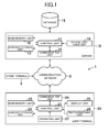
- FIG. 1 illustrates the overall configuration of the electronic commerce system according to the embodiment of the present invention.
- the electronic commerce system according to the embodiment 1 (a clothing image processing system) includes a server 10, a database 16, a user terminal 20, and a store terminal 4. Though omitted from FIG. 1 , the electronic commerce system 1 actually includes a plurality of user terminals 20 and a plurality of store terminals 4.
- the server 10, the user terminal 20, and the store terminal 4 are connected to a communication network 2, which includes the Internet or the like.
- the server 10 and the user terminal 20 can communicate data to and from each other.
- the server 10 and the store terminal 4 can communicate data to and from each other.
- the server 10 is, for example, a virtual shopping mall server which functions as a portal of the virtual shopping mall.
- the server 10 executes processing based on a processing request which is received from the user terminal 20 or the store terminal 4.
- the server 10 includes a control unit 11, a main memory unit 12, an auxiliary storage unit 13, a communication unit 14, and an optical disc drive unit 15.
- the control unit 11 includes, for example, one or a plurality of CPUs, and executes information processing in accordance with an operating system or a program stored in the auxiliary storage unit 13.
- the main memory unit 12 is, for example, a RAM.
- the auxiliary storage unit 13 is, for example, a hard disk or a solid state drive.
- the communication unit 14 is used for performing data communication via the communication network 2.
- the optical disc drive unit 15 is used for reading a program or data recorded on an optical disc (information recording medium).
- the program or data is supplied to the auxiliary storage unit 13 via an optical disc (information recording medium). Specifically, the program or data stored on the optical disc is read by the optical disc drive unit 15 and stored in the auxiliary storage unit 13.
- the server 10 may include a component necessary for reading a program or data stored in an information recording medium (for example, a memory card) other than the optical disc. Then, the program or data may be supplied to the auxiliary storage unit 13 via the information recording medium (for example, a memory card) other than the optical disc. Alternatively, a program or data may be supplied to the auxiliary storage unit 13 via the communication network 2.
- the server 10 is accessible to the database 16.
- the database 16 may be built in the server 10, or may be built in another server than the server 10.
- the database 16 stores, for example, information of users who use the virtual shopping mall, information of stores that open in the virtual shopping mall, information of items dealt with in the virtual shopping mall, and information of transactions made in the virtual shopping mall.
- FIG. 2 and FIG. 3 each show an example of data stored in the database 16.
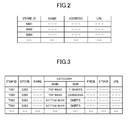
- FIG. 2 shows an example of a store table. Information of stores that open in the virtual shopping mall is registered in the store table.
- the store table of FIG. 2 includes a "store ID” field, a "name” field, an "address” field, and a "URL” field.
- the "store ID” field shows identification information (store ID) for identifying a store that opens in the virtual shopping mall.
- the "name” field shows the name of the store.
- the "address” field shows the address of the store.
- the "URL” field shows information of a link (a URL) to a Web page of the store.
- FIG. 3 shows an example of an item table. Information of items dealt with in the virtual shopping mall is registered in the item table.
- the item table of FIG. 3 includes an "item ID” field, a "store” field, a "name” field, a “category” field, a "price” field, a "stock” field, and a "URL” field.
- the "item ID” field shows identification information for uniquely identifying an item (item ID).
- the "store” field shows the store ID of a store that deals with the item.
- the "name” field shows the name of the item.
- the “category” field shows a main category and sub-category of the item.
- the "price” field shows the price of the item.
- the "stock” field shows how many pieces of the item are in stock.
- the "URL” field shows information of a link (a URL) to a Web page of the item.
- the store terminal 4 is an information processing device that is provided on the store that opens in the virtual shopping mall.
- the store terminal 4 is, for example, a personal computer.
- the store terminal 4 is used to register information of an item to be sold in the virtual shopping mall and other types of information in the database 16 via the server 10. For instance, a special screen which is provided by the server 10 is displayed on the store terminal 4.
- a manager of the store inputs information of the store, information of an item, and the like on the special screen.
- the user terminal 20 is an information processing device that is used by a user.
- the user terminal 20 is, for example, a cell phone (including a smartphone), a portable information terminal, or a personal computer.
- the user terminal 20 in the following description is a cell phone (a smartphone).
- the user terminal 20 includes a control unit 21, a main memory unit 22, an auxiliary storage unit 23, a communication unit 24, a display unit 25, a photographing unit 26, and an operating unit 27.
- the control unit 21, the main memory unit 22, the auxiliary storage unit 23, and the communication unit 24 are the same as the control unit 11, the main memory unit 12, the auxiliary storage unit 13, and the communication unit 14 of the server 10.
- a program or data is supplied to the auxiliary storage unit 23 via the communication network 2.
- the user terminal 20 may include an optical disc drive unit. Then, a program or data may be supplied to the auxiliary storage unit 23 via an optical disc (information recording medium).
- the user terminal 20 may include a component necessary for reading a program or data stored in an information recording medium (for example, a memory card) other than the optical disc. Then, the program or data may be supplied to the auxiliary storage unit 23 via the information recording medium (for example, a memory card) other than the optical disc.
- the display unit 25 is, for example, a liquid crystal display or an organic EL display, and displays various kinds of screens.
- the photographing unit 26 is, for example, a digital camera.
- the photographing unit 26 is capable of taking a still image.
- the photographing unit 26 is also capable of photographing a video.
- the photographing unit 26 takes a picture at given time intervals (e.g., 1/60-second intervals). In other words, the photographing unit 26 photographing a video that has a given number of frames (e.g., sixty frames) per second.
- a still image or video taken by the photographing unit 26 is saved in the auxiliary storage unit 13.
- the operating unit 27 is used by a user for operation.
- a pointing device for allowing the user to specify a position in the screen displayed on the display unit 25 is equipped as the operating unit 27.
- a touch panel overlaid on the display unit 25 is equipped in the user terminal 20.
- the user terminal 20 may include, for example, a mouse, a stick, or a touchpad instead of the touch panel.
- the electronic commerce system 1 allows a user to check various coordinates (combinations of clothing and shoes) when purchasing clothing and shoes. This function is described below.
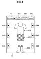
- FIG. 4 illustrates an example of a coordinate screen which is displayed on the display unit 25 of the user terminal 20.
- the coordinate screen 30 of FIG. 4 is displayed based on data transmitted to the user terminal 20 from the server 10.
- a combination of a top wear image 32A, a bottom wear image 32B, and a shoe image 32C is displayed on the coordinate screen 30.
- the top wear image 32A is an image of a top wear that is selected from among top wears sold in the virtual shopping mall.
- the bottom wear image 32B is an image of a bottom wear that is selected from among bottom wears sold in the virtual shopping mall
- the shoe image 32C is an image of a pair of shoes that is selected from among pairs of shoes sold in the virtual shopping mall.
- Forward buttons 34A, 34B, and 34C and back buttons 36A, 36B, and 36C are also displayed on the coordinate screen 30. The user presses these buttons to change the combination of the top wear image 32A, the bottom wear image 32B, and the shoe image 32C that are displayed on the coordinate screen 30.
- a plurality of top wear images 32A are displayed on the coordinate screen 30 in a given order.
- the forward button 34A and the back button 36A are buttons for switching the top wear image 32A that is displayed on the coordinate screen 30. With the press of the forward button 34A, the next top wear image 32A is displayed on the coordinate screen 30. On the other hand, with the press of the back button 36A, the preceding top wear image 32A is displayed on the coordinate screen 30.
- a plurality of bottom wear images 32B are displayed on the coordinate screen 30 in a given order.
- the forward button 34B and the back button 36B are buttons for switching the bottom wear image 32B that is displayed on the coordinate screen 30. With the press of the forward button 34B, the next bottom wear image 32B is displayed on the coordinate screen 30. On the other hand, with the press of the back button 36B, the preceding bottom wear image 32B is displayed on the coordinate screen 30.
- a plurality of shoe images 32C further displayed on the coordinate screen 30 in a given order.
- the forward button 34C and the back button 36C are buttons for switching the shoe image 32C that is displayed on the coordinate screen 30. With the press of the forward button 34C, the next shoe image 32C is displayed on the coordinate screen 30. On the other hand, with the press of the back button 36C, the preceding shoe image 32C is displayed on the coordinate screen 30.
- a top wear button 38A, a bottom wear button 38B, and a shoes button 38C are also displayed on the coordinate screen 30.
- the top wear button 38A is a button for starting the automatic switching of the top wear image 32A that is displayed on the coordinate screen 30. With the press of the top wear button 38A, the top wear image 32A that is displayed on the coordinate screen 30 is switched automatically at given time intervals (e.g., 2-second intervals) in a given order. When the top wear button 38A is pressed again, the automatic switching of the top wear image 32A that is displayed on the coordinate screen 30 is stopped.
- time intervals e.g., 2-second intervals
- the bottom wear button 38B is a button for starting the automatic switching of the bottom wear image 32B that is displayed on the coordinate screen 30.
- the bottom wear image 32B that is displayed on the coordinate screen 30 is switched automatically at given time intervals (e.g., 2-second intervals) in a given order.
- time intervals e.g., 2-second intervals
- the shoes button 38C is a button for starting the automatic switching of the shoe image 32C that is displayed on the coordinate screen 30. With the press of the shoes button 38C, the shoe image 32C that is displayed on the coordinate screen 30 is switched automatically at given time intervals (e.g., 2-second intervals) in a given order. When the shoes button 38C is pressed again, the automatic switching of the shoe image 32C that is displayed on the coordinate screen 30 is stopped.
- time intervals e.g., 2-second intervals
- a background field 40 is also displayed on the coordinate screen 30.
- the background field 40 is for selecting a background of the coordinate screen 30.
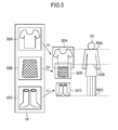
- FIG. 5 is a diagram that explains the coordinate screen 30 in detail.
- the top wear image 32A, the bottom wear image 32B, and the shoe image 32C are displayed on the coordinate screen 30 in a balance close to the balance of the actual sizes of the top wear, the bottom wear, and the pair of shoes.
- the top wear image 32A, the bottom wear image 32B, and the shoe image 32C are each adjusted in size (enlarged or reduced) on the coordinate screen 30 (arrows A, B, and C in FIG. 5 ) and, as a result, the top wear image 32A, the bottom wear image 32B, and the shoe image 32C are displayed in a balance close to the balance of the actual sizes of the top wear, the bottom wear, and the pair of shoes.
- the top wear image 32A, the bottom wear image 32B, and the shoe image 32C are also displayed on the coordinate screen 30 so that the positional relation between the images corresponds to the positional relation between the shoulders, waists (the hips), and feet of a person.
- the top wear image 32A is displayed according to a position of a shoulder part 50A of a virtual human body model 50.
- the bottom wear image 32B is displayed according to a position of a waist part 50B of the virtual human body model 50.
- the shoe image 32C is displayed according to a position of a sole part 50C of the virtual human body model 50.
- the top wear image 32A is set to the highest priority level and the shoe image 32C is set to the lowest priority level on the coordinate screen 30. Accordingly, when the top wear image 32A partially overlaps with the bottom wear image 32B or the shoe image 32C, the top wear image 32A is displayed preferentially. When the bottom wear image 32B partially overlaps with the shoe image 32C, the bottom wear image 32B is displayed preferentially.
- the following description is about a configuration for displaying the coordinate screen 30 described above. Processing for generating the top wear image 32A, the bottom wear image 32B, and the shoe image 32C to be stored in the database 16 is described first.
- the top wear image 32A, the bottom wear image 32B, and the shoe image 32C are each generated based on, for example, a photographed image of a top wear, a bottom wear, or a pair of shoes.
- FIG. 6 is a flow chart illustrating an example of the processing for generating the top wear image 32A, the bottom wear image 32B, and the shoe image 32C.
- the processing of FIG. 6 is executed in, for example, the server 10.
- the server 10 (a clothing image processing device) executes the processing of FIG. 6 when, for example, item information is newly registered by a person in charge of the store and a photographed image of a top wear, a bottom wear, or a pair of shoes is transmitted to the server 10.
- top wear image 32A or the bottom wear image 32B A case of generating the top wear image 32A or the bottom wear image 32B based on a photographed image of a top wear or a bottom wear is described first.
- a photographed image of a top wear or a bottom wear is referred to as "clothing image”.
- the control unit 11 of the server 10 first detects a background area in the clothing image (S101).
- background area means an area other than an area (a clothing area) where the piece of clothing is photographed.
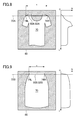
- FIG. 7A, FIG. 7B, and FIG. 7C are diagrams that explains an example of how a background area is detected.
- FIG. 7A illustrates an example of a clothing image to be processed by background area detecting processing.
- the clothing image 60 of FIG. 7A is a photographed image of a top wear worn on a mannequin.
- the clothing image 60 is an image in which the piece of clothing is photographed against a background of a solid color or a background that has colors similar to one another.
- the color of the clothing area is not the same or similar to the colors of other areas than the clothing area.
- control unit 11 To detect a background area in the clothing image 60, the control unit 11 first sets pixel lines (pixel rows and pixel columns) adjacent to the four sides of the clothing image 60 as a background area 62 as illustrated in FIG. 7B .
- control unit 11 determines whether or not an adjacent pixel which is adjacent to a pixel in the background area 62 has a color that is the same as or similar to the color of the pixel in the background area 62.
- An "adjacent pixel" is a pixel that is adjacent to a pixel in the background area 62 and that is not included in the background area 62.
- control unit 11 determines whether or not the degree of similarity between the color of the pixel in the background area 62 and the color of the adjacent pixel is higher than a reference similarity. When the degree of similarity is higher than the reference similarity, the control unit 11 determines that the adjacent pixel has a color that is the same as or similar to the color of the pixel in the background area 62.
- control unit 11 calculates the Euclidean distance between the color value (for example, RGB value) of the pixel in the background area 62 and the color value (for example, RGB value) of the adjacent pixel.
- the control unit 11 determines whether or not the calculated Euclidean distance is smaller than a reference value. When the Euclidean distance is smaller than the reference value, the control unit 11 determines that the adjacent pixel has a color that is the same as or similar to the color of the pixel in the background area 62.
- Color may be expressed by other color values than the RGB value. For instance, a color value in the CIELAB color space or the HSV color space is used in some cases.
- the method of determining whether or not two colors are the same as or similar to each other is not limited to the one that uses the Euclidean distance. For instance, the mean square error, the Mahalanobis distance, or the Earth Mover's distance may be used to determine whether or not two colors are the same as or similar to each other.
- the control unit 11 When it is determined that the adjacent pixel has a color that is the same as or similar to the color of the pixel in the background area 62, the control unit 11 adds this adjacent pixel to the background area 62. The control unit 11 expands the background area 62 in this manner.
- the processing described above is executed repeatedly until no more adjacent pixel is found that is the same as or similar to a pixel in the background area 62 in color.
- the background area 62 as the one illustrated in FIG. 7C is detected as a result.
- Step S101 the control unit 11 removes the background area 62 in the clothing image 60 (S102).
- the control unit 11 makes the background area 62 in the clothing image 60 transparent.
- the control unit 11 After executing Step S102, the control unit 11 obtains a size adjustment line and a position adjustment line (S103).
- the "size adjustment line” is used as a reference for adjusting the size of a clothing image (the term includes the top wear image 32A and the bottom wear image 32B).
- the "position adjustment line”, on the other hand, is used as a reference for adjusting the display position of a clothing image (the term includes the top wear image 32A and the bottom wear image 32B) on the coordinate screen 30. Details of roles of the size adjustment line and the position adjustment line are described later.
- FIG. 8 is a diagram that explains an example of how the size adjustment line and the position adjustment line are obtained in the case where the clothing image 60 is a top wear image.
- a size adjustment line 80A is obtained by detecting a shoulder line 72A.
- the control unit 11 first converts the clothing image 60 into a binary image.
- FIG. 8 illustrates the clothing image 60 that has been converted into a binary image.
- the control unit 11 counts the number of pixels that are included in a clothing area 70 (the counted number (N)).
- a graph in FIG. 8 shows a histogram of the counted number (N) of the respective pixel rows.
- the shoulder line 72A is detected by examining the slope of the histogram because the curvature tends to be large in the shoulder part in the case of a top wear image. Specifically, the control unit 11 examines changes in a curvature ⁇ (y) of the histogram from the top of the clothing image 60 in order.
- Changes in the curvature ⁇ (y) are calculated by calculating an inner product through the following Expression (1) based on the histogram hist (y) described above. For example, when the vertical sides and lateral sides of the clothing image 60 are both 400 pixels in length, a height h is set to 5 pixels to obtain the curvature ⁇ (y).
- the control unit 11 examines the curvature ⁇ (y) from the top of the clothing image 60 in order, and detects a point where a change in the curvature ⁇ (y) exceeds a given value (e.g., 180 ⁇ ) for the first time as the shoulder position. In other words, the control unit 11 detects as the shoulder line 72A a pixel row where a change in the curvature ⁇ (y) exceeds a given value (e.g., 180°) for the first time.
- a given value e.g. 180 ⁇
- the control unit 11 then obtains, as the size adjustment line 80A, a part of the pixel row detected as the shoulder line 72A that is between a left edge 74L of the clothing area 70 and a right edge 74R of the clothing area 70.
- the control unit 11 also sets the size adjustment line 80A as a position adjustment line 82A in the case of a top wear image.
- FIG. 9 is a diagram that explains an example of how the size adjustment line and the position adjustment line are obtained in the case where the clothing image 60 is a bottom wear image.
- a size adjustment line 80B is obtained by detecting a waist line 72B.
- the control unit 11 first converts the clothing image 60 into a binary image.
- FIG. 9 illustrates the clothing image 60 that has been converted into a binary image.
- the control unit 11 counts the number of pixels that are included in a clothing area 70 (the counted number (N)).
- a graph in FIG. 9 shows a histogram of the counted number (N) of the respective pixel rows.
- the waist line 72B is detected by examining the slope of the histogram because the curvature tends to be large in the waist part in the case of a bottom wear image.
- the control unit 11 examines changes in a curvature ⁇ (y) of the histogram from the top of the clothing image 60 in order. Changes in the curvature ⁇ (y) are calculated by calculating an inner product through the above-mentioned Expression (1) based on the histogram hist(y) described above.
- the control unit 11 examines the curvature ⁇ (y) from the top of the clothing image 60 in order, and detects a point where a change in the curvature ⁇ (y) exceeds a given value (e.g., 180°) for the first time as the waist position. In other words, the control unit 11 detects as the waist line 72B a pixel row where a change in the curvature ⁇ (y) exceeds a given value (e.g., 180°) for the first time.
- a given value e.g. 180°
- the control unit 11 then obtains, as the size adjustment line 80B, a part of the pixel row detected as the waist line 72B that is between a left edge 74L of the clothing area 70 and a right edge 74R of the clothing area 70. Similarly to the top wear image, the control unit 11 also sets the size adjustment line 80B as a position adjustment line 82B in the case of a bottom wear image.
- the size adjustment lines 80A and 80B may collectively be referred to as "size adjustment lines 80”
- the position adjustment lines 82A and 82B may collectively be referred to as "position adjustment lines 82".
- Step S103 the control unit 11 executes processing for normalizing the clothing image 60. Because the size (scale) and position of the piece of clothing (clothing area) in the clothing image 60 varies from one clothing image 60 to another, the size and center position of the clothing image 60 is adjusted in the following steps based on the size adjustment line 80 detected in Step S103.
- the control unit 11 first obtains a length (s) of the size adjustment line 80 (S104).
- the length (s) of the size adjustment line 80A is the width of the clothing area 70 along the shoulder line 72A, in other words, the length of a part of the shoulder line 72A from one edge (the left edge 74L) of the clothing area 70 to the other edge (the right edge 74R) of the clothing area 70.
- the length (s) of the size adjustment line 80B is the width of the clothing area 70 along the waist line 72B, in other words, the length of a part of the waist line 72B from one edge (the left edge 74L) of the clothing area 70 to the other edge (the right edge 74R) of the clothing area 70.
- Step S104 the control unit 11 enlarges or reduces the clothing image 60 so that the length (s) of the size adjustment line 80 equals a given length (S) (S105).
- control unit 11 determines an enlargement ratio or a reduction ratio that makes the length (s) of the size adjustment line 80 equal to the given length (S), based on the degree of difference between the length (s) of the size adjustment line 80 and the given length (S). Specifically, the control unit 11 obtains the enlargement ratio or the reduction ratio by dividing the given length (S) by the length (s) of the size adjustment line 80. The control unit 11 then enlarges or reduces the clothing image 60 according to the determined enlargement ratio or reduction ratio.
- Step S105 the control unit 11 adjusts the horizontal position (the position in an X-axis direction) of the clothing area 70 in the clothing image 60 (S106).
- control unit 11 moves the clothing area 70 within the clothing image 60 in a horizontal direction (the positive or negative X-axis direction) so that the midpoint of the size adjustment line 80 is positioned on a line that runs through the center point of the clothing image 60 and that extends in a vertical direction (a Y-axis direction).
- the control unit 11 also adjusts the vertical position (the position in a Y-axis direction) of the clothing area 70 in the clothing image 60 (S107).
- control unit 11 moves the clothing area 70 within the clothing image 60 in a vertical direction (the positive or negative Y-axis direction) so that the size adjustment line 80 is positioned at a given distance (d pixels) from the upper side of the clothing image 60.
- the control unit 11 further trims the clothing image 60 so that the clothing image 60 has a given width (w) (S108).
- the control unit 11 saves the thus normalized clothing image 60 in the database 16 as the top wear image 32A or the bottom wear image 32B (S109).
- the case of generating the shoe image 32C based on a photographed image of a pair of shoes is basically the same as the case of generating the top wear image 32A or the bottom wear image 32B.
- the method of obtaining the size adjustment line 80 and the position adjustment line 82 in the case of generating the shoe image 32C based on a photographed image of a pair of shoes differs from the case of generating the top wear image 32A or the bottom wear image 32B based on a photographed image of a top wear or a bottom wear.
- Shoe shape varies greatly depending on shoe type, such as boots and pumps. It is therefore difficult to obtain the size adjustment line 80 in an appropriate manner by using changes in curvature as in the case of a top wear image ( FIG. 8 ) or a bottom wear image ( FIG. 9 ). Accordingly, a method different from the one for top wear images and bottom wear images is used to obtain the size adjustment line 80 and the position adjustment line 82 in the case of a shoe image.
- FIG. 10 is a diagram that explains an example of how the size adjustment line 80 and the position adjustment line 82 of the shoe image are obtained.
- the control unit 11 first obtains a height (H) of a shoe area 92. Specifically, the control unit 11 obtains a distance between a first pixel line 94A (pixel row) that runs through the uppermost part of the shoe area 92 and a second pixel line 94B (pixel row) that runs through the lowermost part of the shoe area 92.
- the control unit 11 also obtains a third pixel line 94C, which makes the ratio of its distance from the first pixel line 94A and its distance from the second pixel line 94B equal to a given ratio (for example, 1:2).
- the third pixel line 94C is a pixel line that is placed below (the positive Y-axis direction) the first pixel line 94A at a distance obtained by multiplying the height (H) by a given coefficient ⁇ (0 ⁇ 1, for example, 1/3).
- the control unit 11 then obtains, as a size adjustment line 80C, a part of the third pixel line 94C that is between a left edge 96L of the shoe area 92 and a right edge 96R of the shoe area 92.
- the control unit 11 also obtains the second pixel line 94B as a position adjustment line 82C.
- the clothing image 60 (the top wear image 32A or the bottom wear image 32B) and a shoe image 90 (the shoe image 32C) that are saved in the database 16 in Step S109 of FIG. 6 are managed via an image table.
- FIG. 11 shows an example of the image table.
- Various types of information on the clothing image 60 (the top wear image 32A or the bottom wear image 32B) and the shoe image 90 (the shoe image 32C) that are saved in the database 16 are registered in the image table.
- the image table is stored in the database 16.
- the image table includes an "image ID” field, an "item” field, a “URL” field, a “size adjustment line” field, and a "position adjustment line” field.
- the "image ID field” shows identification information (an image ID) for uniquely identifying an image.
- the “item” field shows which item is depicted by the image. In the case of an image of an item that has an item ID "T001", for example, the item ID "T001" is registered in the "item” field.
- the "URL” field shows information of a link to the image.
- the "size adjustment line” field shows the position and length of the size adjustment line 80.
- the "position adjustment line” field shows the position of the position adjustment line 82.
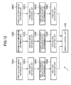
- FIG. 12 is a functional block diagram illustrating function blocks for displaying the coordinate screen 30 out of the function blocks implemented in the electronic commerce system 1.
- the function blocks of FIG. 12 are each implemented by the user terminal 20 or the server 10.
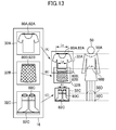
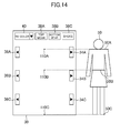
- FIG. 13 and FIG. 14 are diagrams that explain the function blocks.
- the electronic commerce system 1 includes a first clothing image obtaining unit 100A, a first width obtaining unit 102A, a first enlargement/reduction ratio determining unit 104A, and a first size adjusting unit 106A. These function blocks are components for displaying the top wear image 32A on the coordinate screen 30.
- the first clothing image obtaining unit 100A obtains a first clothing image which is an image of a first piece of clothing worn on the upper half of the body.
- a top wear corresponds to the "first piece of clothing” and the top wear image 32A corresponds to the "first clothing image”.
- the first clothing image obtaining unit 100A obtains the top wear image 32A.
- the first width obtaining unit 102A obtains the width of the shoulder part of the top wear in the top wear image 32A. Specifically, the first width obtaining unit 102A obtains the length of the size adjustment line 80A in the top wear image 32A.
- the first enlargement/reduction ratio determining unit 104A determines an enlargement ratio or a reduction ratio for the top wear image 32A based on the degree of difference between the width obtained by the first width obtaining unit 102A and a given first reference length.
- a width (Ls) of the shoulder part 50A of the virtual human body model 50 is set as the "first reference length", and the first enlargement/reduction ratio determining unit 104A obtains an enlargement ratio or a reduction ratio that makes the length of the size adjustment line 80A in the top wear image 32A equal to the first reference length (Ls). Specifically, the first enlargement/reduction ratio determining unit 104A obtains the enlargement ratio or the reduction ratio by dividing the first reference length (Ls) by the length of the size adjustment line 80A in the top wear image 32A.
- the first size adjusting unit 106A adjusts the size of the top wear image 32A based on the width obtained by the first width obtaining unit 102A. In other words, the first size adjusting unit 106A adjusts the size of the top wear image 32A based on the length of the size adjustment line 80A in the top wear image 32A.
- the first size adjusting unit 106A in this embodiment enlarges or reduces the top wear image 32A based on the enlargement ratio or reduction ratio determined by the first enlargement/reduction ratio determining unit 104A (see an arrow A in FIG. 13 ).
- the electronic commerce system 1 further includes a second clothing image obtaining unit 100B, a second width obtaining unit 102B, a second enlargement/reduction ratio determining unit 104B, and a second size adjusting unit 106B.
- These function blocks are components for displaying the bottom wear image 32B on the coordinate screen 30.
- the second clothing image obtaining unit 100B obtains a second clothing image which is an image of a second piece of clothing worn on the lower half of the body.
- a bottom wear corresponds to the "second piece of clothing”
- the bottom wear image 32B corresponds to the "second clothing image”.
- the second clothing image obtaining unit 100B obtains the bottom wear image 32B.
- the second width obtaining unit 102B obtains the width of the waist part of the bottom wear in the bottom wear image 32B. Specifically, the second width obtaining unit 102B obtains the length of the size adjustment line 80B in the bottom wear image 32B.
- the second enlargement/reduction ratio determining unit 104B determines an enlargement ratio or a reduction ratio for the bottom wear image 32B based on the degree of difference between the width obtained by the second width obtaining unit 102B and a given second reference length.
- a width (La) of the waist part 50B of the virtual human body model 50 as illustrated in FIG. 13 is set as the "second reference length", and the second enlargement/reduction ratio determining unit 104B obtains an enlargement ratio or a reduction ratio that makes the length of the size adjustment line 80B in the bottom wear image 32B equal to the second reference length (La). Specifically, the second enlargement/reduction ratio determining unit 104B obtains the enlargement ratio or the reduction ratio by dividing the second reference length (La) by the length of the size adjustment line 80B in the bottom wear image 32B.
- the second size adjusting unit 106B adjusts the size of the bottom wear image 32B based on the width obtained by the second width obtaining unit 102B. In other words, the second size adjusting unit 106B adjusts the size of the bottom wear image 32B based on the length of the size adjustment line 80B in the bottom wear image 32B.
- the second size adjusting unit 106B in this embodiment enlarges or reduces the bottom wear image 32B based on the enlargement ratio or reduction ratio determined by the second enlargement/reduction ratio determining unit 104B (see an arrow B in FIG. 13 ).
- the electronic commerce system 1 further includes a third clothing image obtaining unit 100C, a third width obtaining unit 102C, a third enlargement/reduction ratio determining unit 104C, and a third size adjusting unit 106C.
- These function blocks are components for displaying the shoe image 32C on the coordinate screen 30.
- the third clothing image obtaining unit 100C obtains the shoe image 32C stored in the database 16.
- the third width obtaining unit 102C obtains the width of the pair of shoes in the shoe image 32C. In other words, the third width obtaining unit 102C obtains the length of the size adjustment line 80C in the shoe image 32C.
- the third enlargement/reduction ratio determining unit 104C determines an enlargement ratio or a reduction ratio for the shoe image 32C based on the degree difference between the width obtained by the third width obtaining unit 102C and a given third reference length.
- a width (Ll) of a foot part of the virtual human body model 50 as illustrated in FIG. 13 is set as the "third reference length", and the third enlargement/reduction ratio determining unit 104C obtains an enlargement ratio or a reduction ratio that makes the length of the size adjustment line 80C in the shoe image 32C equal to the third reference length (Ll). Specifically, the third enlargement/reduction ratio determining unit 104C obtains the enlargement ratio or the reduction ratio by dividing the third reference length (Ll) by the length of the size adjustment line 80C in the shoe image 32C.
- the third size adjusting unit 106C adjusts the size of the shoe image 32C based on the width obtained by the third width obtaining unit 102C. In other words, the third size adjusting unit 106C adjusts the size of the shoe image 32C based on the length of the size adjustment line 80C in the shoe image 32C.
- the third size adjusting unit 106C in this embodiment enlarges or reduces the shoe image 32C based on the enlargement ratio or reduction ratio determined by the third enlargement/reduction ratio determining unit 104C (see an arrow C in FIG. 13 ).
- the electronic commerce system 1 further includes a display control unit 108 as illustrated in FIG. 12 .
- the display control unit 108 displays, on the display unit 25, the coordinate screen 30 for displaying a top wear, a bottom wear, and a pair of shoes on top of one another.
- the display control unit 108 displays the coordinate screen 30 on the display unit 25 based on the top wear image 32A that has been adjusted by the first size adjusting unit 106A, the bottom wear image 32B that has been adjusted by the second size adjustment unit 106B, and the shoe image 32C that has been adjusted by the third size adjustment unit 106C.
- a point 110A which corresponds to the shoulder part 50A of the virtual human body model 50 is set in the coordinate screen 30.
- the display control unit 108 displays, on the coordinate screen 30, the top wear image 32A that has been adjusted by the first size adjusting unit 106A so that the midpoint of the position adjustment line 82A matches the point 110A.
- a point 110B which corresponds to the waist part 50B of the virtual human body model 50 is set in the coordinate screen 30.
- the display control unit 108 displays, on the coordinate screen 30, the bottom wear image 32B that has been adjusted by the second size adjusting unit 106B so that the midpoint of the position adjustment line 82B matches the point 110B.
- a point 110C which corresponds to the sole part 50C of the virtual human body model 50 (in other words, a surface of the ground) is set in the coordinate screen 30.
- the display control unit 108 displays, on the coordinate screen 30, the shoe image 32C that has been adjusted by the third size adjusting unit 106C so that the midpoint of the position adjustment line 82C matches the point 110C.
- FIG. 15 and FIG. 16 are diagrams explaining processing that is executed in the electronic commerce system 1 to start displaying the coordinate screen 30.
- the control unit 21 of the user terminal 20 (clothing image processing device) executes the processing of FIG. 15 and FIG. 16 according to a program, thus enabling the control unit 21 to function as the function blocks of FIG. 12 .
- the control unit 21 of the user terminal 20 first requests a list of the top wear images 32A, the bottom wear images 32B, and the shoe images 32C from the server 10 as illustrated in FIG. 15 (S201).
- the control unit 11 selects a given number of top wear images 32A, a given number of bottom wear images 32B, and a given number of shoe images 32C that are to be displayed on the coordinate screen 30, and returns a list of these top wear images 32A, bottom wear images 32B, and shoe images 32C to the user terminal 20 (S202).
- various types of information registered in the image table are transmitted to the user terminal 20.
- the control unit 21 When the user terminal 20 receives the list, the control unit 21 initializes variables i, j, and k to 1 (S203).
- the role of the variable i is to indicate the ordinal number of the top wear image 32A that is being displayed on the coordinate screen 30.
- the variable j indicates the ordinal number of the bottom wear image 32B that is being displayed on the coordinate screen 30, and the variable k indicates the ordinal number of the shoe image 32C that is being displayed on the coordinate screen 30.
- the control unit 21 requests the i-th top wear image 32A from the server 10 (S204).
- the plurality of top wear images 32A selected to be displayed on the coordinate screen 30 are sorted in a given order (for example, in ascending order of image ID).
- the control unit 21 requests from the server 10 the i-th top wear image 32A out of the plurality of top wear images 32A selected to be displayed on the coordinate screen 30.
- the control unit 11 transmits the top wear image 32A to the user terminal 20 (S205).
- the control unit 21 determines an enlargement ratio or a reduction ratio for the top wear image 32A (S206).
- the control unit 21 obtains the enlargement ratio or the reduction ratio by dividing the first reference length (Ls) by the length of the size adjustment line 80A of the top wear image 32A.
- the control unit 21 enlarges or reduces the top wear image 32A according to the enlargement ratio or reduction ratio determined in Step S206 (S207), and displays the top wear image 32A that has been enlarged or reduced on the coordinate screen 30 (S208).
- the display position of the top wear image 32A is set so that the midpoint of the position adjustment line 82A of the top wear image 32A matches the point 110A which corresponds to the shoulder part 50A of the virtual human body model 50.
- control unit 21 requests from the server 10 the j-th bottom wear image 32B out of the plurality of bottom wear images 32B selected to be displayed on the coordinate screen 30 (S209).
- the control unit 11 transmits the requested bottom wear image 32B to the user terminal 20 (S210).
- the control unit 21 determines an enlargement ratio or a reduction ratio for the bottom wear image 32B (S211).
- the control unit 21 obtains the enlargement ratio or the reduction ratio by dividing the second reference length (La) by the length of the size adjustment line 80B of the bottom wear image 32B.
- the control unit 21 enlarges or reduces the bottom wear image 32B according to the enlargement ratio or reduction ratio determined in Step S211 (S212), and displays the bottom wear image 32B that has been enlarged or reduced on the coordinate screen 30 (S213).
- the display position of the bottom wear image 32B is set so that the midpoint of the position adjustment line 82B of the bottom wear image 32B matches the point 110B which corresponds to the waist part 50B of the virtual human body model 50.
- control unit 21 requests from the server 10 the k-th shoe image 32C out of the plurality of shoe images 32C selected to be displayed on the coordinate screen 30 (S214).
- the control unit 11 transmits the requested shoe image 32C to the user terminal 20 (S215).
- the control unit 21 determines an enlargement ratio or a reduction ratio for the bottom image 32C (S216).
- the control unit 21 obtains the enlargement ratio or the reduction ratio by dividing the third reference length (Ll) by the length of the size adjustment line 80C of the shoe image 32C.
- the control unit 21 enlarges or reduces the shoe image 32C according to the enlargement ratio or reduction ratio determined in Step S216 (S217), and displays the shoe image 32C that has been enlarged or reduced on the coordinate screen 30 (S218).
- the display position of the shoe image 32C is set so that the midpoint of the position adjustment line 82C of the shoe image 32C matches the point 110C which corresponds to the sole part 50C of the virtual human body model 50 (the surface of the ground). This concludes the description about processing that is executed to start displaying the coordinate screen 30.
- Steps S209 to S213 the value of the variable j is incremented or decremented and then the same processing as Steps S209 to S213 is executed.
- the value of the variable k is incremented or decremented and then the same processing as Steps S214 to S218 is executed.
- Steps S204 to S208 are executed repeatedly.
- Steps S209 to S213 are executed repeatedly.
- Steps S214 to S218 are executed repeatedly.
- the electronic commerce system 1 (clothing image processing system) according to this embodiment which has been described automatically adjusts the respective sizes of the top wear image 32A, the bottom wear image 32B, and the shoe image 32C according to the virtual human body model 50 (the arrows A, B, and C of FIG. 13 ) and, as a result, the top wear image 32A, the bottom wear image 32B, and the shoe image 32C are displayed in a balance that is close to the balance of the actual sizes of the top wear, the bottom wear, and the pair of shoes.
- an operator of the electronic commerce system or others generates clothing images adjusted to the body shape of a mannequin or an avatar by performing image size adjustment and trimming while checking photographed images of top wears, bottom wears, or pairs of shoes one by one, in order to display the top wear image 32A, the bottom wear image 32B, and the shoe image 32C in a balance close to the balance of the actual sizes of the top wear, the bottom wear, and the pair of shoes.
- Such work is very laborious and increases working hours and cost.
- clothing images in which the same piece of clothing is photographed from a plurality of angles are prepared, but this increases working hours and cost.
- the electronic commerce system 1 according to this embodiment can keep working hours short and cost low.
- the electronic commerce system 1 according to this embodiment is also capable of changing the size of the virtual human body model 50 according to the user's gender, age, or body shape. Even when the size of the virtual human body model 50 is changed, the electronic commerce system 1 according to this embodiment can easily adjust the respective sizes of the top wear image 32A, the bottom wear image 32B, and the shoe image 32C according to the changed virtual human body model 50.
- the present invention is not limited to the embodiment described above.
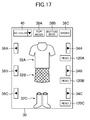
- FIG. 17 illustrates another example of the coordinate screen 30.
- the coordinate screen 30 of FIG. 17 differs from the coordinate screen 30 of FIG. 4 in that read buttons 120A, 120B, and 120C are included.
- the read button 120A is a button for displaying on the coordinate screen 30 a top wear image that is, for example, photographed by the user or obtained by the user from a Web page or other places.
- the press of the read button 120A causes the display unit 25 to display a selection screen (not shown) for selecting a top wear image.
- the user takes a picture of a top wear that the user owns in advance and selects the photographed image on the selection screen.
- An image selected on the selection screen is transmitted to the server 10.
- the server 10 in this case executes the processing of FIG. 6 for the received image.
- the image is returned to the user terminal 20.
- the user terminal 20 executes the same processing as Steps S206 to S208 of FIG. 15 .
- the top wear owned by the user is displayed on the coordinate screen 30.
- a photographing screen for taking a picture may be displayed when the read button 120A is pressed. An image taken on the photographing screen is transmitted to the server 10.
- the read button 120B is a button for displaying on the coordinate screen 30 a bottom wear image that is photographed by the user or obtained by the user from a Web page or other places.
- the read button 120C is a button for displaying on the coordinate screen 30 a shoe image that is photographed by the user or obtained by the user from a Web page or other places.
- the user can check how well an item coordinates with, for example, the user's clothes.
- FIG. 18 illustrates still another example of the coordinate screen 30.
- the coordinate screen 30 of FIG. 18 differs from the coordinate screens 30 of FIG. 4 and FIG. 17 in that a "specify condition" button 130 is included.
- the "specify condition” button 130 is a button for specifying conditions about top wears, bottom wears, and pairs of shoes to be displayed on the coordinate screen 30.
- a condition specifying screen is displayed when the "specify condition" button 130 is pressed.
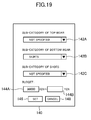
- FIG. 19 illustrates an example of the condition specifying screen.
- the condition specifying screen 140 is a screen for receiving the specification of conditions about top wear images, bottom wear images, and shoe images to be displayed on the coordinate screen 30.
- the condition specifying screen 140 includes selection fields 142A, 142B, and 142C as illustrated in FIG. 19 .
- the selection field 142A is for receiving the specification of a sub-category of top wears to be displayed on the coordinate screen 30.
- the top wear image 32A that is displayed on the coordinate screen 30 is limited to images of top wears that belong to the selected sub-category.
- the selection field 142B is for receiving the specification of a sub-category of bottom wears to be displayed on the coordinate screen 30.
- the bottom wear image 32B that is displayed on the coordinate screen 30 is limited to images of bottom wears that belong to the selected sub-category.
- the selection field 142C is for receiving the specification of a sub-category of pairs of shoes to be displayed on the coordinate screen 30.
- the shoe image 32C that is displayed on the coordinate screen 30 is limited to images of pairs of shoes that belong to the selected sub-category.
- the condition specifying screen 140 also includes budget fields 144A and 144B.
- the budget field 144A is for receiving the specification of a lower limit to budget
- the budget field 144B is for receiving the specification of an upper limit to budget.
- a combination of a top wear, a bottom wear, and a pair of shoes whose total price is equal to or more than the amount of money input in the budget field 144A is displayed on the coordinate screen 30.
- a combination of a top wear, a bottom wear, and a pair of shoes whose total price is equal to or less than the amount of money input in the budget field 144B is displayed on the coordinate screen 30.
- the condition specifying screen 140 also includes a set button 146 and a cancel button 148.
- the press of the cancel button 148 returns the screen to the coordinate screen 30.
- condition specifying screen 140 When the set button 146 is pressed, conditions specified on the condition specifying screen 140 are transmitted to the server 10.
- the server 10 in this case searches for pieces of clothing and pairs of shoes that satisfy the conditions, and transmits a list of the top wear images 32A, the bottom wear images 32B, and the shoe images 32C of the found clothing and shoes to the user terminal 20.
- the user terminal 20 displays the coordinate screen 30 based on the list.
Landscapes
- Engineering & Computer Science (AREA)
- Physics & Mathematics (AREA)
- Theoretical Computer Science (AREA)
- General Physics & Mathematics (AREA)
- Business, Economics & Management (AREA)
- Accounting & Taxation (AREA)
- Finance (AREA)
- General Business, Economics & Management (AREA)
- Strategic Management (AREA)
- Marketing (AREA)
- Economics (AREA)
- Development Economics (AREA)
- Computer Vision & Pattern Recognition (AREA)
- Processing Or Creating Images (AREA)
- Image Processing (AREA)
- Management, Administration, Business Operations System, And Electronic Commerce (AREA)
- Treatment Of Fiber Materials (AREA)
Abstract
Description
- The present invention relates to a clothing image processing system, a method of controlling a clothing image processing system, a clothing image processing device, a method of controlling a clothing image processing device, a program, and an information recording medium.
- An increasing number of users are using electronic commerce to purchase fashion-related items in recent years. In many sites that sell fashion-related items, clothing images are displayed in a list format, as is the case for commercial goods of other genres. In some of sites that sell fashion-related items, a photographed image of a person or mannequin wearing a combination of pieces of clothing (for example, a combination of a top wear and a bottom wear) selected by the seller is displayed. A "top wear" is a piece of clothing worn on the upper half of the body, and a "bottom wear" is a piece of clothing worn on the lower half of the body.
- [Patent Literature 1]
JP 2008-217320 A - Users who uses electronic commerce to purchase fashion-related items wish to check various clothing combinations (coordinates) while shopping. This wish could be fulfilled by, for example, displaying a top wear image and a bottom wear image one above the other on the screen so that various combinations (coordinates) of a top wear and a bottom wear are presented to users.
- However, many clothing images are photographed in a manner that gives as large a view as possible of a piece of clothing that is the subject of the photographed image, and the size (scale) of the piece of clothing in the image consequently varies from one clothing image to another, depending on the shape and the like of the piece of clothing. Therefore, when a top wear image and a bottom wear image are simply displayed one above the other on the screen, the balance between the sizes (scales) of the top wear and the bottom wear displayed on the screen may differ significantly from the balance between the actual sizes of the top wear and the bottom wear, thereby giving a sense of strangeness to users.
- The present invention has been made in view of the problem described above, and an object of the present invention is therefore to provide a clothing image processing system, a method of controlling a clothing image processing system, a clothing image processing device, a method of controlling a clothing image processing device, a program, and an information recording medium with which, on a screen on which a combination of a top wear image and a bottom wear image is displayed, for example, the balance between the sizes (scales) of the top wear and the bottom wear is made closer to the balance between the actual sizes of the top wear and the bottom wear.
- In order to solve the above-mentioned problem, a clothing image processing system according to one embodiment of the present invention is a clothing image processing system, including: first clothing image obtaining means for obtaining a first clothing image which is an image of a first piece of clothing worn on an upper half of a body; first width obtaining means for obtaining a width of a shoulder part of the first piece of clothing in the first clothing image; first size adjusting means for adjusting a size of the first clothing image based on the width obtained by the first width obtaining means; second clothing image obtaining means for obtaining a second clothing image which is an image of a second piece of clothing worn on a lower half of the body; second width obtaining means for obtaining a width of a waist part of the second piece of clothing in the second clothing image; second size adjusting means for adjusting a size of the second clothing image based on the width obtained by the second width obtaining means; and display control means for causing display means to display a screen on which the first piece of clothing and the second piece of clothing are vertically displayed, based on the first clothing image that has been adjusted by the first size adjusting means and the second clothing image that has been adjusted by the second size adjusting means.
- Further, a method of controlling a clothing image processing system according to one embodiment of the present invention is a method of controlling a clothing image processing system, the method including: a first clothing image obtaining step of obtaining a first clothing image which is an image of a first piece of clothing worn on an upper half of a body; a first width obtaining step of obtaining a width of a shoulder part of the first piece of clothing in the first clothing image; a first size adjusting step of adjusting a size of the first clothing image based on the width obtained in the first width obtaining step; a second clothing image obtaining step of obtaining a second clothing image which is an image of a second piece of clothing worn on a lower half of the body; a second width obtaining step of obtaining a width of a waist part of the second piece of clothing in the second clothing image; a second size adjusting step of adjusting a size of the second clothing image based on the width obtained in the second width obtaining step; and a display control step of causing display means to display a screen on which the first piece of clothing and the second piece of clothing are vertically displayed, based on the first clothing image that has been adjusted in the first size adjusting step and the second clothing image that has been adjusted in the second size adjusting step.
- Further, a clothing image processing device according to one embodiment of the present invention is a clothing image processing device, including: first clothing image obtaining means for obtaining a first clothing image which is an image of a first piece of clothing worn on an upper half of a body; first width obtaining means for obtaining a width of a shoulder part of the first piece of clothing in the first clothing image; first size adjusting means for adjusting a size of the first clothing image based on the width obtained by the first width obtaining means; second clothing image obtaining means for obtaining a second clothing image which is an image of a second piece of clothing worn on a lower half of the body; second width obtaining means for obtaining a width of a waist part of the second piece of clothing in the second clothing image; and second size adjusting means for adjusting a size of the second clothing image based on the width obtained by the second width obtaining means.
- Further, a method of controlling a clothing image processing device according to one embodiment of the present invention is a method of controlling a clothing image processing device, the method including: a first clothing image obtaining step of obtaining a first clothing image which is an image of a first piece of clothing worn on an upper half of a body; a first width obtaining step of obtaining a width of a shoulder part of the first piece of clothing in the first clothing image; a first size adjusting step of adjusting a size of the first clothing image based on the width obtained in the first width obtaining step; a second clothing image obtaining step of obtaining a second clothing image which is an image of a second piece of clothing worn on a lower half of the body; a second width obtaining step of obtaining a width of a waist part of the second piece of clothing in the second clothing image; and a second size adjusting step of adjusting a size of the second clothing image based on the width obtained in the second width obtaining step.
- Further, a program according to one embodiment of the present invention is a program for causing a computer to function as: first clothing image obtaining means for obtaining a first clothing image which is an image of a first piece of clothing worn on an upper half of a body; first width obtaining means for obtaining a width of a shoulder part of the first piece of clothing in the first clothing image; first size adjusting means for adjusting a size of the first clothing image based on the width obtained by the first width obtaining means; second clothing image obtaining means for obtaining a second clothing image which is an image of a second piece of clothing worn on a lower half of the body; second width obtaining means for obtaining a width of a waist part of the second piece of clothing in the second clothing image; and second size adjusting means for adjusting a size of the second clothing image based on the width obtained by the second width obtaining means.
- Further, a computer-readable information recording medium according to one embodiment of the present invention is a computer-readable information recording medium having recorded thereon a program for causing a computer to function as: first clothing image obtaining means for obtaining a first clothing image which is an image of a first piece of clothing worn on an upper half of a body; first width obtaining means for obtaining a width of a shoulder part of the first piece of clothing in the first clothing image; first size adjusting means for adjusting a size of the first clothing image based on the width obtained by the first width obtaining means; second clothing image obtaining means for obtaining a second clothing image which is an image of a second piece of clothing worn on a lower half of the body; second width obtaining means for obtaining a width of a waist part of the second piece of clothing in the second clothing image; and second size adjusting means for adjusting a size of the second clothing image based on the width obtained by the second width obtaining means.
- Further, according to an aspect of the present invention, the clothing image processing system may further include: background area detecting means for detecting a background area in a clothing image; and background area removing means for removing the background area from the clothing image, and the background area detecting means may include: means for initially setting, as the background area, pixel lines adjacent to four sides of the clothing image; means for determining whether or not an adjacent pixel, which is adjacent to a pixel in the background area, has a color that is the same as or similar to a color of the pixel in the background area; and means for expanding the background area by adding the adjacent pixel to the background area in a case where the adjacent pixel has the color that is the same as or similar to the color of the pixel in the background area, and the background area is removed from each of the first clothing image and the second clothing image by the background area detecting means and the background area removing means.
- Further, according to an aspect of the present invention, the clothing image processing system may further include: means for obtaining, for each of a plurality of pixel lines in the first clothing image, a number of pixels that are included in an area where the first piece of clothing is shown; and means for detecting a pixel line that corresponds to the shoulder part from among the plurality of pixel lines, based on a frequency distribution on the number of pixels of each of the plurality of pixel lines, and the first width obtaining means may obtain the width of the first piece of clothing along the pixel line that corresponds to the shoulder part.
- Further, according to an aspect of the present invention, the clothing image processing system may further include first enlargement/reduction ratio determining means for determining an enlargement ratio or a reduction ratio for the first clothing image, based on a degree of difference between the width obtained by the first width obtaining means and a given first reference length, and the first size adjusting means may enlarge or reduce the first clothing image based on the enlargement ratio or reduction ratio determined by the first enlargement/reduction ratio determining means.
- Further, according to an aspect of the present invention, the clothing image processing system may further include: means for obtaining, for each of a plurality of pixel lines in the second clothing image, a number of pixels that are included in an area where the second piece of clothing is shown; and means for detecting a pixel line that corresponds to the waist part from among the plurality of pixel lines, based on a frequency distribution on the number of pixels of each of the plurality of pixel lines, and the second width obtaining means may obtain the width of the second piece of clothing along the pixel line that corresponds to the waist part.
- Further, according to an aspect of the present invention, the clothing image processing system may further include second enlargement/reduction ratio determining means for determining an enlargement ratio or a reduction ratio for the second clothing image, based on a degree of difference between the width obtained by the second width obtaining means and a given second reference length, and the second size adjusting means may enlarge or reduce the second clothing image based on the enlargement ratio or reduction ratio determined by the second enlargement/reduction ratio determining means.
- Further, according to an aspect of the present invention, the display control means may cause the display means to display the screen on which the first piece of clothing and the second piece of clothing are displayed in a positional relation corresponding to a positional relation between shoulders and waists of a person, based on the first clothing image that has been adjusted by the first size adjusting means and the second clothing image that has been adjusted by the second size adjusting means.
- Further, according to an aspect of the present invention, the clothing image processing system may further include: shoe image obtaining means for obtaining a shoe image; third width obtaining means for obtaining a width of a pair of shoes in the shoe image, the third width obtaining means obtaining the width of the pair of shoes along a pixel line that is placed below an uppermost part of the shoes at a distance obtained by multiplying a height of the shoes by a given coefficient α (0<α<1); and third size adjusting means for adjusting a size of the shoe image based on the width obtained by the third width obtaining means, and the display control means may cause the display means to display the screen on which the first piece of clothing, the second piece of clothing, and the pair of shoes are vertically displayed, based on the first clothing image that has been adjusted by the first size adjusting means, the second clothing image that has been adjusted by the second size adjusting means, and the shoe image that has been adjusted by the third size adjusting means.
- Further, according to an aspect of the present invention, the clothing image processing system may further include third enlargement/reduction ratio determining means for determining an enlargement ratio or a reduction ratio for the shoe image, based on a degree of difference between the width obtained by the third width obtaining means and a given third reference length, and the third size adjusting means may enlarge or reduce the shoe image based on the enlargement ratio or reduction ratio determined by the third enlargement/reduction ratio determining means.
- Further, according to an aspect of the present invention, the display control means may cause the display means to display the screen on which the first piece of clothing, the second piece of clothing, and the pair of shoes are displayed in a positional relation corresponding to a positional relation between shoulders, waists, and feet of a person, based on the first clothing image that has been adjusted by the first size adjusting means, the second clothing image that has been adjusted by the second size adjusting means, and the shoe image that has been adjusted by the third size adjusting means.
- Further, according to an aspect of the present invention, the clothing image processing system may further include: means for receiving specification of a category of pieces of clothing worn on the upper half of the body; and means for receiving specification of a category of pieces of clothing worn on the lower half of the body, and the display control means may include: means for causing the display means, in a case where the specification of the category of pieces of clothing worn on the upper half of the body is received, to display the screen on which the first piece of clothing that belongs to the specified category is displayed, based on the first clothing image that has been adjusted by the first size adjusting means; and means for causing the display means, in a case where the specification of the category of pieces of clothing worn on the lower half of the body is received, to display the screen on which the second piece of clothing that belongs to the specified category is displayed, based on the second clothing image that has been adjusted by the second size adjusting means.
- Further, according to an aspect of the present invention, the first clothing image obtaining means may include means for obtaining, as the first clothing image, an image of a piece of clothing worn on the upper half of the body that is photographed or specified by a user, and the second clothing image obtaining means may include means for obtaining, as the second clothing image, an image of a piece of clothing worn on the lower half of the body that is photographed or specified by the user.
- According to one embodiment of the present invention, it is possible to make, on the screen on which the combination of the top wear image and the bottom wear image is displayed, for example, the balance between the sizes (scales) of the top wear and the bottom wear closer to the balance between the actual sizes of the top wear and the bottom wear.
-
-
FIG. 1 is a diagram illustrating an example of the overall configuration of an electronic commerce system (clothing image processing system) according to an embodiment of the present invention. -
FIG. 2 is a diagram showing an example of a store table. -
FIG. 3 is a diagram showing an item table. -
FIG. 4 is a diagram illustrating an example of a coordinate screen. -
FIG. 5 is a diagram explaining the coordinate screen. -
FIG. 6 is a flow chart illustrating an example of processing for generating a top wear image, a bottom wear image, or a shoe image. -
FIG. 7A is a diagram explaining an example of how a background area is detected. -
FIG. 7B is a diagram explaining the example of how the background area is detected. -
FIG. 7C is a diagram explaining the example of how the background area is detected. -
FIG. 8 is a diagram explaining an example of how a size adjustment line is obtained in the case of the top wear image. -
FIG. 9 is a diagram explaining the example of how the size adjustment line is obtained in the case of the bottom wear image. -
FIG. 10 is a diagram explaining the example of how the size adjustment line is obtained in the case of the shoe image. -
FIG. 11 is a diagram showing an example of an image table. -
FIG. 12 is a functional block diagram of the electronic commerce system. -
FIG. 13 is a diagram explaining function blocks that are implemented in the electronic commerce system. -
FIG. 14 is a diagram explaining the function blocks that are implemented in the electronic commerce system. -
FIG. 15 is a diagram illustrating an example of processing that is executed in the electronic commerce system. -
FIG. 16 is a diagram illustrating the example of processing that is executed in the electronic commerce system. -
FIG. 17 is a diagram illustrating another example of the coordinate screen. -
FIG. 18 is a diagram illustrating still another example of the coordinate screen. -
FIG. 19 is a diagram illustrating an example of a condition specifying screen. - An exemplary embodiment of the present invention is described below in detail with reference to the drawings. Described here is a case in which the present invention is applied to an electronic commerce system. Specifically, the description is about an example of a case where a clothing image processing system according to the embodiment of the present invention is implemented in an electronic commerce system that implements a virtual shopping mall housing a plurality of stores.
-
FIG. 1 illustrates the overall configuration of the electronic commerce system according to the embodiment of the present invention. As illustrated inFIG. 1 , the electronic commerce system according to the embodiment 1 (a clothing image processing system) includes aserver 10, adatabase 16, auser terminal 20, and astore terminal 4. Though omitted fromFIG. 1 , theelectronic commerce system 1 actually includes a plurality ofuser terminals 20 and a plurality ofstore terminals 4. - The
server 10, theuser terminal 20, and thestore terminal 4 are connected to a communication network 2, which includes the Internet or the like. Theserver 10 and theuser terminal 20 can communicate data to and from each other. Theserver 10 and thestore terminal 4 can communicate data to and from each other. - The
server 10 is, for example, a virtual shopping mall server which functions as a portal of the virtual shopping mall. Theserver 10 executes processing based on a processing request which is received from theuser terminal 20 or thestore terminal 4. Theserver 10 includes acontrol unit 11, amain memory unit 12, anauxiliary storage unit 13, acommunication unit 14, and an opticaldisc drive unit 15. - The
control unit 11 includes, for example, one or a plurality of CPUs, and executes information processing in accordance with an operating system or a program stored in theauxiliary storage unit 13. Themain memory unit 12 is, for example, a RAM. Theauxiliary storage unit 13 is, for example, a hard disk or a solid state drive. Thecommunication unit 14 is used for performing data communication via the communication network 2. The opticaldisc drive unit 15 is used for reading a program or data recorded on an optical disc (information recording medium). - The program or data is supplied to the
auxiliary storage unit 13 via an optical disc (information recording medium). Specifically, the program or data stored on the optical disc is read by the opticaldisc drive unit 15 and stored in theauxiliary storage unit 13. Note that, theserver 10 may include a component necessary for reading a program or data stored in an information recording medium (for example, a memory card) other than the optical disc. Then, the program or data may be supplied to theauxiliary storage unit 13 via the information recording medium (for example, a memory card) other than the optical disc. Alternatively, a program or data may be supplied to theauxiliary storage unit 13 via the communication network 2. - The
server 10 is accessible to thedatabase 16. Thedatabase 16 may be built in theserver 10, or may be built in another server than theserver 10. Thedatabase 16 stores, for example, information of users who use the virtual shopping mall, information of stores that open in the virtual shopping mall, information of items dealt with in the virtual shopping mall, and information of transactions made in the virtual shopping mall.FIG. 2 and FIG. 3 each show an example of data stored in thedatabase 16. -
FIG. 2 shows an example of a store table. Information of stores that open in the virtual shopping mall is registered in the store table. The store table ofFIG. 2 includes a "store ID" field, a "name" field, an "address" field, and a "URL" field. - The "store ID" field shows identification information (store ID) for identifying a store that opens in the virtual shopping mall. The "name" field shows the name of the store. The "address" field shows the address of the store. The "URL" field shows information of a link (a URL) to a Web page of the store.
-
FIG. 3 shows an example of an item table. Information of items dealt with in the virtual shopping mall is registered in the item table. The item table ofFIG. 3 includes an "item ID" field, a "store" field, a "name" field, a "category" field, a "price" field, a "stock" field, and a "URL" field. - The "item ID" field shows identification information for uniquely identifying an item (item ID). The "store" field shows the store ID of a store that deals with the item. The "name" field shows the name of the item. The "category" field shows a main category and sub-category of the item. The "price" field shows the price of the item. The "stock" field shows how many pieces of the item are in stock. The "URL" field shows information of a link (a URL) to a Web page of the item.
- The
store terminal 4 is an information processing device that is provided on the store that opens in the virtual shopping mall. Thestore terminal 4 is, for example, a personal computer. Thestore terminal 4 is used to register information of an item to be sold in the virtual shopping mall and other types of information in thedatabase 16 via theserver 10. For instance, a special screen which is provided by theserver 10 is displayed on thestore terminal 4. A manager of the store inputs information of the store, information of an item, and the like on the special screen. - The
user terminal 20 is an information processing device that is used by a user. Theuser terminal 20 is, for example, a cell phone (including a smartphone), a portable information terminal, or a personal computer. Theuser terminal 20 in the following description is a cell phone (a smartphone). - The
user terminal 20 includes acontrol unit 21, amain memory unit 22, anauxiliary storage unit 23, acommunication unit 24, adisplay unit 25, a photographingunit 26, and anoperating unit 27. Thecontrol unit 21, themain memory unit 22, theauxiliary storage unit 23, and thecommunication unit 24 are the same as thecontrol unit 11, themain memory unit 12, theauxiliary storage unit 13, and thecommunication unit 14 of theserver 10. - A program or data is supplied to the
auxiliary storage unit 23 via the communication network 2. Note that, theuser terminal 20 may include an optical disc drive unit. Then, a program or data may be supplied to theauxiliary storage unit 23 via an optical disc (information recording medium). Alternatively, theuser terminal 20 may include a component necessary for reading a program or data stored in an information recording medium (for example, a memory card) other than the optical disc. Then, the program or data may be supplied to theauxiliary storage unit 23 via the information recording medium (for example, a memory card) other than the optical disc. - The
display unit 25 is, for example, a liquid crystal display or an organic EL display, and displays various kinds of screens. The photographingunit 26 is, for example, a digital camera. The photographingunit 26 is capable of taking a still image. The photographingunit 26 is also capable of photographing a video. For instance, the photographingunit 26 takes a picture at given time intervals (e.g., 1/60-second intervals). In other words, the photographingunit 26 photographing a video that has a given number of frames (e.g., sixty frames) per second. A still image or video taken by the photographingunit 26 is saved in theauxiliary storage unit 13. - The operating
unit 27 is used by a user for operation. For example, a pointing device for allowing the user to specify a position in the screen displayed on thedisplay unit 25 is equipped as the operatingunit 27. For example, a touch panel overlaid on thedisplay unit 25 is equipped in theuser terminal 20. Note that, theuser terminal 20 may include, for example, a mouse, a stick, or a touchpad instead of the touch panel. - The
electronic commerce system 1 allows a user to check various coordinates (combinations of clothing and shoes) when purchasing clothing and shoes. This function is described below. -
FIG. 4 illustrates an example of a coordinate screen which is displayed on thedisplay unit 25 of theuser terminal 20. The coordinatescreen 30 ofFIG. 4 is displayed based on data transmitted to theuser terminal 20 from theserver 10. - As illustrated in
FIG. 4 , a combination of atop wear image 32A, abottom wear image 32B, and ashoe image 32C is displayed on the coordinatescreen 30. Thetop wear image 32A is an image of a top wear that is selected from among top wears sold in the virtual shopping mall. Similarly, thebottom wear image 32B is an image of a bottom wear that is selected from among bottom wears sold in the virtual shopping mall, and theshoe image 32C is an image of a pair of shoes that is selected from among pairs of shoes sold in the virtual shopping mall. -
Forward buttons back buttons screen 30. The user presses these buttons to change the combination of thetop wear image 32A, thebottom wear image 32B, and theshoe image 32C that are displayed on the coordinatescreen 30. - A plurality of
top wear images 32A are displayed on the coordinatescreen 30 in a given order. Theforward button 34A and theback button 36A are buttons for switching thetop wear image 32A that is displayed on the coordinatescreen 30. With the press of theforward button 34A, the nexttop wear image 32A is displayed on the coordinatescreen 30. On the other hand, with the press of theback button 36A, the precedingtop wear image 32A is displayed on the coordinatescreen 30. - Similarly, a plurality of
bottom wear images 32B are displayed on the coordinatescreen 30 in a given order. Theforward button 34B and theback button 36B are buttons for switching thebottom wear image 32B that is displayed on the coordinatescreen 30. With the press of theforward button 34B, the nextbottom wear image 32B is displayed on the coordinatescreen 30. On the other hand, with the press of theback button 36B, the precedingbottom wear image 32B is displayed on the coordinatescreen 30. - A plurality of
shoe images 32C further displayed on the coordinatescreen 30 in a given order. Theforward button 34C and theback button 36C are buttons for switching theshoe image 32C that is displayed on the coordinatescreen 30. With the press of theforward button 34C, thenext shoe image 32C is displayed on the coordinatescreen 30. On the other hand, with the press of theback button 36C, the precedingshoe image 32C is displayed on the coordinatescreen 30. - A
top wear button 38A, abottom wear button 38B, and ashoes button 38C are also displayed on the coordinatescreen 30. - The
top wear button 38A is a button for starting the automatic switching of thetop wear image 32A that is displayed on the coordinatescreen 30. With the press of thetop wear button 38A, thetop wear image 32A that is displayed on the coordinatescreen 30 is switched automatically at given time intervals (e.g., 2-second intervals) in a given order. When thetop wear button 38A is pressed again, the automatic switching of thetop wear image 32A that is displayed on the coordinatescreen 30 is stopped. - Similarly, the
bottom wear button 38B is a button for starting the automatic switching of thebottom wear image 32B that is displayed on the coordinatescreen 30. With the press of thebottom wear button 38B, thebottom wear image 32B that is displayed on the coordinatescreen 30 is switched automatically at given time intervals (e.g., 2-second intervals) in a given order. When thebottom wear button 38B is pressed again, the automatic switching of thebottom wear image 32B that is displayed on the coordinatescreen 30 is stopped. - The
shoes button 38C is a button for starting the automatic switching of theshoe image 32C that is displayed on the coordinatescreen 30. With the press of theshoes button 38C, theshoe image 32C that is displayed on the coordinatescreen 30 is switched automatically at given time intervals (e.g., 2-second intervals) in a given order. When theshoes button 38C is pressed again, the automatic switching of theshoe image 32C that is displayed on the coordinatescreen 30 is stopped. - A
background field 40 is also displayed on the coordinatescreen 30. Thebackground field 40 is for selecting a background of the coordinatescreen 30. -
FIG. 5 is a diagram that explains the coordinatescreen 30 in detail. Thetop wear image 32A, thebottom wear image 32B, and theshoe image 32C are displayed on the coordinatescreen 30 in a balance close to the balance of the actual sizes of the top wear, the bottom wear, and the pair of shoes. Specifically, thetop wear image 32A, thebottom wear image 32B, and theshoe image 32C are each adjusted in size (enlarged or reduced) on the coordinate screen 30 (arrows A, B, and C inFIG. 5 ) and, as a result, thetop wear image 32A, thebottom wear image 32B, and theshoe image 32C are displayed in a balance close to the balance of the actual sizes of the top wear, the bottom wear, and the pair of shoes. - The
top wear image 32A, thebottom wear image 32B, and theshoe image 32C are also displayed on the coordinatescreen 30 so that the positional relation between the images corresponds to the positional relation between the shoulders, waists (the hips), and feet of a person. Specifically, thetop wear image 32A is displayed according to a position of ashoulder part 50A of a virtualhuman body model 50. Thebottom wear image 32B is displayed according to a position of awaist part 50B of the virtualhuman body model 50. Theshoe image 32C is displayed according to a position of asole part 50C of the virtualhuman body model 50. - The
top wear image 32A is set to the highest priority level and theshoe image 32C is set to the lowest priority level on the coordinatescreen 30. Accordingly, when thetop wear image 32A partially overlaps with thebottom wear image 32B or theshoe image 32C, thetop wear image 32A is displayed preferentially. When thebottom wear image 32B partially overlaps with theshoe image 32C, thebottom wear image 32B is displayed preferentially. - The following description is about a configuration for displaying the coordinate
screen 30 described above. Processing for generating thetop wear image 32A, thebottom wear image 32B, and theshoe image 32C to be stored in thedatabase 16 is described first. - The
top wear image 32A, thebottom wear image 32B, and theshoe image 32C are each generated based on, for example, a photographed image of a top wear, a bottom wear, or a pair of shoes. -
FIG. 6 is a flow chart illustrating an example of the processing for generating thetop wear image 32A, thebottom wear image 32B, and theshoe image 32C. The processing ofFIG. 6 is executed in, for example, theserver 10. The server 10 (a clothing image processing device) executes the processing ofFIG. 6 when, for example, item information is newly registered by a person in charge of the store and a photographed image of a top wear, a bottom wear, or a pair of shoes is transmitted to theserver 10. - A case of generating the
top wear image 32A or thebottom wear image 32B based on a photographed image of a top wear or a bottom wear is described first. In the following description, a photographed image of a top wear or a bottom wear is referred to as "clothing image". - As illustrated in
FIG. 6 , thecontrol unit 11 of theserver 10 first detects a background area in the clothing image (S101). The term "background area" means an area other than an area (a clothing area) where the piece of clothing is photographed. -
FIG. 7A, FIG. 7B, and FIG. 7C are diagrams that explains an example of how a background area is detected.FIG. 7A illustrates an example of a clothing image to be processed by background area detecting processing. Theclothing image 60 ofFIG. 7A is a photographed image of a top wear worn on a mannequin. Theclothing image 60 is an image in which the piece of clothing is photographed against a background of a solid color or a background that has colors similar to one another. In theclothing image 60 ofFIG. 7A , the color of the clothing area is not the same or similar to the colors of other areas than the clothing area. - To detect a background area in the
clothing image 60, thecontrol unit 11 first sets pixel lines (pixel rows and pixel columns) adjacent to the four sides of theclothing image 60 as abackground area 62 as illustrated inFIG. 7B . - Thereafter, the
control unit 11 determines whether or not an adjacent pixel which is adjacent to a pixel in thebackground area 62 has a color that is the same as or similar to the color of the pixel in thebackground area 62. An "adjacent pixel" is a pixel that is adjacent to a pixel in thebackground area 62 and that is not included in thebackground area 62. - For instance, the
control unit 11 determines whether or not the degree of similarity between the color of the pixel in thebackground area 62 and the color of the adjacent pixel is higher than a reference similarity. When the degree of similarity is higher than the reference similarity, thecontrol unit 11 determines that the adjacent pixel has a color that is the same as or similar to the color of the pixel in thebackground area 62. - More specifically, the
control unit 11 calculates the Euclidean distance between the color value (for example, RGB value) of the pixel in thebackground area 62 and the color value (for example, RGB value) of the adjacent pixel. Thecontrol unit 11 determines whether or not the calculated Euclidean distance is smaller than a reference value. When the Euclidean distance is smaller than the reference value, thecontrol unit 11 determines that the adjacent pixel has a color that is the same as or similar to the color of the pixel in thebackground area 62. - Color may be expressed by other color values than the RGB value. For instance, a color value in the CIELAB color space or the HSV color space is used in some cases. The method of determining whether or not two colors are the same as or similar to each other is not limited to the one that uses the Euclidean distance. For instance, the mean square error, the Mahalanobis distance, or the Earth Mover's distance may be used to determine whether or not two colors are the same as or similar to each other.
- When it is determined that the adjacent pixel has a color that is the same as or similar to the color of the pixel in the
background area 62, thecontrol unit 11 adds this adjacent pixel to thebackground area 62. Thecontrol unit 11 expands thebackground area 62 in this manner. - The processing described above is executed repeatedly until no more adjacent pixel is found that is the same as or similar to a pixel in the
background area 62 in color. Thebackground area 62 as the one illustrated inFIG. 7C is detected as a result. - After executing Step S101, the
control unit 11 removes thebackground area 62 in the clothing image 60 (S102). Thecontrol unit 11 makes thebackground area 62 in theclothing image 60 transparent. - After executing Step S102, the
control unit 11 obtains a size adjustment line and a position adjustment line (S103). The "size adjustment line" is used as a reference for adjusting the size of a clothing image (the term includes thetop wear image 32A and thebottom wear image 32B). The "position adjustment line", on the other hand, is used as a reference for adjusting the display position of a clothing image (the term includes thetop wear image 32A and thebottom wear image 32B) on the coordinatescreen 30. Details of roles of the size adjustment line and the position adjustment line are described later. -
FIG. 8 is a diagram that explains an example of how the size adjustment line and the position adjustment line are obtained in the case where theclothing image 60 is a top wear image. When theclothing image 60 is a top wear image, asize adjustment line 80A is obtained by detecting ashoulder line 72A. - The
control unit 11 first converts theclothing image 60 into a binary image.FIG. 8 illustrates theclothing image 60 that has been converted into a binary image. - Thereafter, for each pixel row in the clothing image 60 (namely, each pixel line that extends in a direction corresponding to the lateral direction of the piece of clothing), the
control unit 11 counts the number of pixels that are included in a clothing area 70 (the counted number (N)). A graph inFIG. 8 shows a histogram of the counted number (N) of the respective pixel rows. - The
shoulder line 72A is detected by examining the slope of the histogram because the curvature tends to be large in the shoulder part in the case of a top wear image. Specifically, thecontrol unit 11 examines changes in a curvature θ (y) of the histogram from the top of theclothing image 60 in order. - Changes in the curvature θ(y) are calculated by calculating an inner product through the following Expression (1) based on the histogram hist (y) described above. For example, when the vertical sides and lateral sides of the
clothing image 60 are both 400 pixels in length, a height h is set to 5 pixels to obtain the curvature θ(y).
[Mathematical Expression 1]
- The
control unit 11 examines the curvature θ(y) from the top of theclothing image 60 in order, and detects a point where a change in the curvature θ(y) exceeds a given value (e.g., 180□) for the first time as the shoulder position. In other words, thecontrol unit 11 detects as theshoulder line 72A a pixel row where a change in the curvature θ(y) exceeds a given value (e.g., 180°) for the first time. - The
control unit 11 then obtains, as thesize adjustment line 80A, a part of the pixel row detected as theshoulder line 72A that is between aleft edge 74L of theclothing area 70 and aright edge 74R of theclothing area 70. Thecontrol unit 11 also sets thesize adjustment line 80A as aposition adjustment line 82A in the case of a top wear image. -
FIG. 9 is a diagram that explains an example of how the size adjustment line and the position adjustment line are obtained in the case where theclothing image 60 is a bottom wear image. When theclothing image 60 is a bottom wear image, asize adjustment line 80B is obtained by detecting awaist line 72B. - The
control unit 11 first converts theclothing image 60 into a binary image. Similarly toFIG. 8, FIG. 9 illustrates theclothing image 60 that has been converted into a binary image. - Thereafter, for each pixel row in the clothing image 60 (namely, each pixel line that extends in a direction corresponding to the lateral direction of the piece of clothing), the
control unit 11 counts the number of pixels that are included in a clothing area 70 (the counted number (N)). A graph inFIG. 9 shows a histogram of the counted number (N) of the respective pixel rows. - Similarly to the top wear image, the
waist line 72B is detected by examining the slope of the histogram because the curvature tends to be large in the waist part in the case of a bottom wear image. Specifically, thecontrol unit 11 examines changes in a curvature θ(y) of the histogram from the top of theclothing image 60 in order. Changes in the curvature θ(y) are calculated by calculating an inner product through the above-mentioned Expression (1) based on the histogram hist(y) described above. - The
control unit 11 examines the curvature θ(y) from the top of theclothing image 60 in order, and detects a point where a change in the curvature θ(y) exceeds a given value (e.g., 180°) for the first time as the waist position. In other words, thecontrol unit 11 detects as thewaist line 72B a pixel row where a change in the curvature θ(y) exceeds a given value (e.g., 180°) for the first time. - The
control unit 11 then obtains, as thesize adjustment line 80B, a part of the pixel row detected as thewaist line 72B that is between aleft edge 74L of theclothing area 70 and aright edge 74R of theclothing area 70. Similarly to the top wear image, thecontrol unit 11 also sets thesize adjustment line 80B as aposition adjustment line 82B in the case of a bottom wear image. In the following description, thesize adjustment lines position adjustment lines - After executing Step S103, the
control unit 11 executes processing for normalizing theclothing image 60. Because the size (scale) and position of the piece of clothing (clothing area) in theclothing image 60 varies from oneclothing image 60 to another, the size and center position of theclothing image 60 is adjusted in the following steps based on the size adjustment line 80 detected in Step S103. - The
control unit 11 first obtains a length (s) of the size adjustment line 80 (S104). - In the case of
FIG. 8 (a top wear image), the length (s) of thesize adjustment line 80A is the width of theclothing area 70 along theshoulder line 72A, in other words, the length of a part of theshoulder line 72A from one edge (theleft edge 74L) of theclothing area 70 to the other edge (theright edge 74R) of theclothing area 70. - Similarly, in the case of
FIG. 9 (a bottom wear image), the length (s) of thesize adjustment line 80B is the width of theclothing area 70 along thewaist line 72B, in other words, the length of a part of thewaist line 72B from one edge (theleft edge 74L) of theclothing area 70 to the other edge (theright edge 74R) of theclothing area 70. - After executing Step S104, the
control unit 11 enlarges or reduces theclothing image 60 so that the length (s) of the size adjustment line 80 equals a given length (S) (S105). - In other words, the
control unit 11 determines an enlargement ratio or a reduction ratio that makes the length (s) of the size adjustment line 80 equal to the given length (S), based on the degree of difference between the length (s) of the size adjustment line 80 and the given length (S). Specifically, thecontrol unit 11 obtains the enlargement ratio or the reduction ratio by dividing the given length (S) by the length (s) of the size adjustment line 80. Thecontrol unit 11 then enlarges or reduces theclothing image 60 according to the determined enlargement ratio or reduction ratio. - After executing Step S105, the
control unit 11 adjusts the horizontal position (the position in an X-axis direction) of theclothing area 70 in the clothing image 60 (S106). - For instance, the
control unit 11 moves theclothing area 70 within theclothing image 60 in a horizontal direction (the positive or negative X-axis direction) so that the midpoint of the size adjustment line 80 is positioned on a line that runs through the center point of theclothing image 60 and that extends in a vertical direction (a Y-axis direction). - The
control unit 11 also adjusts the vertical position (the position in a Y-axis direction) of theclothing area 70 in the clothing image 60 (S107). - For instance, the
control unit 11 moves theclothing area 70 within theclothing image 60 in a vertical direction (the positive or negative Y-axis direction) so that the size adjustment line 80 is positioned at a given distance (d pixels) from the upper side of theclothing image 60. - The
control unit 11 further trims theclothing image 60 so that theclothing image 60 has a given width (w) (S108). Thecontrol unit 11 saves the thus normalizedclothing image 60 in thedatabase 16 as thetop wear image 32A or thebottom wear image 32B (S109). - A case of generating the
shoe image 32C based on a photographed image of a pair of shoes is described next. - The case of generating the
shoe image 32C based on a photographed image of a pair of shoes is basically the same as the case of generating thetop wear image 32A or thebottom wear image 32B. - However, the method of obtaining the size adjustment line 80 and the position adjustment line 82 in the case of generating the
shoe image 32C based on a photographed image of a pair of shoes differs from the case of generating thetop wear image 32A or thebottom wear image 32B based on a photographed image of a top wear or a bottom wear. - Shoe shape varies greatly depending on shoe type, such as boots and pumps. It is therefore difficult to obtain the size adjustment line 80 in an appropriate manner by using changes in curvature as in the case of a top wear image (
FIG. 8 ) or a bottom wear image (FIG. 9 ). Accordingly, a method different from the one for top wear images and bottom wear images is used to obtain the size adjustment line 80 and the position adjustment line 82 in the case of a shoe image. -
FIG. 10 is a diagram that explains an example of how the size adjustment line 80 and the position adjustment line 82 of the shoe image are obtained. - The
control unit 11 first obtains a height (H) of ashoe area 92. Specifically, thecontrol unit 11 obtains a distance between afirst pixel line 94A (pixel row) that runs through the uppermost part of theshoe area 92 and asecond pixel line 94B (pixel row) that runs through the lowermost part of theshoe area 92. - The
control unit 11 also obtains athird pixel line 94C, which makes the ratio of its distance from thefirst pixel line 94A and its distance from thesecond pixel line 94B equal to a given ratio (for example, 1:2). Thethird pixel line 94C is a pixel line that is placed below (the positive Y-axis direction) thefirst pixel line 94A at a distance obtained by multiplying the height (H) by a given coefficient α (0<α<1, for example, 1/3). - The
control unit 11 then obtains, as asize adjustment line 80C, a part of thethird pixel line 94C that is between aleft edge 96L of theshoe area 92 and aright edge 96R of theshoe area 92. Thecontrol unit 11 also obtains thesecond pixel line 94B as aposition adjustment line 82C. - The clothing image 60 (the
top wear image 32A or thebottom wear image 32B) and a shoe image 90 (theshoe image 32C) that are saved in thedatabase 16 in Step S109 ofFIG. 6 are managed via an image table.FIG. 11 shows an example of the image table. Various types of information on the clothing image 60 (thetop wear image 32A or thebottom wear image 32B) and the shoe image 90 (theshoe image 32C) that are saved in thedatabase 16 are registered in the image table. The image table is stored in thedatabase 16. - As shown in
FIG. 11 , the image table includes an "image ID" field, an "item" field, a "URL" field, a "size adjustment line" field, and a "position adjustment line" field. The "image ID field" shows identification information (an image ID) for uniquely identifying an image. The "item" field shows which item is depicted by the image. In the case of an image of an item that has an item ID "T001", for example, the item ID "T001" is registered in the "item" field. - The "URL" field shows information of a link to the image. The "size adjustment line" field shows the position and length of the size adjustment line 80. The "position adjustment line" field shows the position of the position adjustment line 82.
- Function blocks implemented in the
electronic commerce system 1 are described next.FIG. 12 is a functional block diagram illustrating function blocks for displaying the coordinatescreen 30 out of the function blocks implemented in theelectronic commerce system 1. The function blocks ofFIG. 12 are each implemented by theuser terminal 20 or theserver 10. - The function blocks of
FIG. 12 are described below.FIG. 13 andFIG. 14 are diagrams that explain the function blocks. - As illustrated in
FIG. 12 , theelectronic commerce system 1 includes a first clothingimage obtaining unit 100A, a firstwidth obtaining unit 102A, a first enlargement/reductionratio determining unit 104A, and a firstsize adjusting unit 106A. These function blocks are components for displaying thetop wear image 32A on the coordinatescreen 30. - The first clothing
image obtaining unit 100A obtains a first clothing image which is an image of a first piece of clothing worn on the upper half of the body. In this embodiment, a top wear corresponds to the "first piece of clothing" and thetop wear image 32A corresponds to the "first clothing image". In short, the first clothingimage obtaining unit 100A obtains thetop wear image 32A. - The first
width obtaining unit 102A obtains the width of the shoulder part of the top wear in thetop wear image 32A. Specifically, the firstwidth obtaining unit 102A obtains the length of thesize adjustment line 80A in thetop wear image 32A. - The first enlargement/reduction
ratio determining unit 104A determines an enlargement ratio or a reduction ratio for thetop wear image 32A based on the degree of difference between the width obtained by the firstwidth obtaining unit 102A and a given first reference length. - In this embodiment, a width (Ls) of the
shoulder part 50A of the virtualhuman body model 50 is set as the "first reference length", and the first enlargement/reductionratio determining unit 104A obtains an enlargement ratio or a reduction ratio that makes the length of thesize adjustment line 80A in thetop wear image 32A equal to the first reference length (Ls). Specifically, the first enlargement/reductionratio determining unit 104A obtains the enlargement ratio or the reduction ratio by dividing the first reference length (Ls) by the length of thesize adjustment line 80A in thetop wear image 32A. - The first
size adjusting unit 106A adjusts the size of thetop wear image 32A based on the width obtained by the firstwidth obtaining unit 102A. In other words, the firstsize adjusting unit 106A adjusts the size of thetop wear image 32A based on the length of thesize adjustment line 80A in thetop wear image 32A. - The first
size adjusting unit 106A in this embodiment enlarges or reduces thetop wear image 32A based on the enlargement ratio or reduction ratio determined by the first enlargement/reductionratio determining unit 104A (see an arrow A inFIG. 13 ). - As illustrated in
FIG. 12 , theelectronic commerce system 1 further includes a second clothingimage obtaining unit 100B, a secondwidth obtaining unit 102B, a second enlargement/reductionratio determining unit 104B, and a secondsize adjusting unit 106B. These function blocks are components for displaying thebottom wear image 32B on the coordinatescreen 30. - The second clothing
image obtaining unit 100B obtains a second clothing image which is an image of a second piece of clothing worn on the lower half of the body. In this embodiment, a bottom wear corresponds to the "second piece of clothing" and thebottom wear image 32B corresponds to the "second clothing image". In short, the second clothingimage obtaining unit 100B obtains thebottom wear image 32B. - The second
width obtaining unit 102B obtains the width of the waist part of the bottom wear in thebottom wear image 32B. Specifically, the secondwidth obtaining unit 102B obtains the length of thesize adjustment line 80B in thebottom wear image 32B. - The second enlargement/reduction
ratio determining unit 104B determines an enlargement ratio or a reduction ratio for thebottom wear image 32B based on the degree of difference between the width obtained by the secondwidth obtaining unit 102B and a given second reference length. - In this embodiment, a width (La) of the
waist part 50B of the virtualhuman body model 50 as illustrated inFIG. 13 is set as the "second reference length", and the second enlargement/reductionratio determining unit 104B obtains an enlargement ratio or a reduction ratio that makes the length of thesize adjustment line 80B in thebottom wear image 32B equal to the second reference length (La). Specifically, the second enlargement/reductionratio determining unit 104B obtains the enlargement ratio or the reduction ratio by dividing the second reference length (La) by the length of thesize adjustment line 80B in thebottom wear image 32B. - The second
size adjusting unit 106B adjusts the size of thebottom wear image 32B based on the width obtained by the secondwidth obtaining unit 102B. In other words, the secondsize adjusting unit 106B adjusts the size of thebottom wear image 32B based on the length of thesize adjustment line 80B in thebottom wear image 32B. - The second
size adjusting unit 106B in this embodiment enlarges or reduces thebottom wear image 32B based on the enlargement ratio or reduction ratio determined by the second enlargement/reductionratio determining unit 104B (see an arrow B inFIG. 13 ). - As illustrated in
FIG. 12 , theelectronic commerce system 1 further includes a third clothingimage obtaining unit 100C, a thirdwidth obtaining unit 102C, a third enlargement/reductionratio determining unit 104C, and a thirdsize adjusting unit 106C. These function blocks are components for displaying theshoe image 32C on the coordinatescreen 30. - The third clothing
image obtaining unit 100C obtains theshoe image 32C stored in thedatabase 16. The thirdwidth obtaining unit 102C obtains the width of the pair of shoes in theshoe image 32C. In other words, the thirdwidth obtaining unit 102C obtains the length of thesize adjustment line 80C in theshoe image 32C. - The third enlargement/reduction
ratio determining unit 104C determines an enlargement ratio or a reduction ratio for theshoe image 32C based on the degree difference between the width obtained by the thirdwidth obtaining unit 102C and a given third reference length. - In this embodiment, a width (Ll) of a foot part of the virtual
human body model 50 as illustrated inFIG. 13 is set as the "third reference length", and the third enlargement/reductionratio determining unit 104C obtains an enlargement ratio or a reduction ratio that makes the length of thesize adjustment line 80C in theshoe image 32C equal to the third reference length (Ll). Specifically, the third enlargement/reductionratio determining unit 104C obtains the enlargement ratio or the reduction ratio by dividing the third reference length (Ll) by the length of thesize adjustment line 80C in theshoe image 32C. - The third
size adjusting unit 106C adjusts the size of theshoe image 32C based on the width obtained by the thirdwidth obtaining unit 102C. In other words, the thirdsize adjusting unit 106C adjusts the size of theshoe image 32C based on the length of thesize adjustment line 80C in theshoe image 32C. - The third
size adjusting unit 106C in this embodiment enlarges or reduces theshoe image 32C based on the enlargement ratio or reduction ratio determined by the third enlargement/reductionratio determining unit 104C (see an arrow C inFIG. 13 ). - The
electronic commerce system 1 further includes adisplay control unit 108 as illustrated inFIG. 12 . Thedisplay control unit 108 displays, on thedisplay unit 25, the coordinatescreen 30 for displaying a top wear, a bottom wear, and a pair of shoes on top of one another. - The
display control unit 108 displays the coordinatescreen 30 on thedisplay unit 25 based on thetop wear image 32A that has been adjusted by the firstsize adjusting unit 106A, thebottom wear image 32B that has been adjusted by the secondsize adjustment unit 106B, and theshoe image 32C that has been adjusted by the thirdsize adjustment unit 106C. - As illustrated in
FIG. 14 , apoint 110A which corresponds to theshoulder part 50A of the virtualhuman body model 50 is set in the coordinatescreen 30. Thedisplay control unit 108 displays, on the coordinatescreen 30, thetop wear image 32A that has been adjusted by the firstsize adjusting unit 106A so that the midpoint of theposition adjustment line 82A matches thepoint 110A. - Similarly, a
point 110B which corresponds to thewaist part 50B of the virtualhuman body model 50 is set in the coordinatescreen 30. Thedisplay control unit 108 displays, on the coordinatescreen 30, thebottom wear image 32B that has been adjusted by the secondsize adjusting unit 106B so that the midpoint of theposition adjustment line 82B matches thepoint 110B. - Further, a
point 110C which corresponds to thesole part 50C of the virtual human body model 50 (in other words, a surface of the ground) is set in the coordinatescreen 30. Thedisplay control unit 108 displays, on the coordinatescreen 30, theshoe image 32C that has been adjusted by the thirdsize adjusting unit 106C so that the midpoint of theposition adjustment line 82C matches thepoint 110C. - Processing that is executed in the
electronic commerce system 1 to start displaying the coordinatescreen 30 is described next.FIG. 15 andFIG. 16 are diagrams explaining processing that is executed in theelectronic commerce system 1 to start displaying the coordinatescreen 30. Thecontrol unit 21 of the user terminal 20 (clothing image processing device) executes the processing ofFIG. 15 andFIG. 16 according to a program, thus enabling thecontrol unit 21 to function as the function blocks ofFIG. 12 . - To start displaying the coordinate
screen 30, thecontrol unit 21 of theuser terminal 20 first requests a list of thetop wear images 32A, thebottom wear images 32B, and theshoe images 32C from theserver 10 as illustrated inFIG. 15 (S201). - When the
server 10 receives the request, thecontrol unit 11 selects a given number oftop wear images 32A, a given number ofbottom wear images 32B, and a given number ofshoe images 32C that are to be displayed on the coordinatescreen 30, and returns a list of thesetop wear images 32A,bottom wear images 32B, andshoe images 32C to the user terminal 20 (S202). In this case, for each of thetop wear images 32A, thebottom wear images 32B, and theshoe image 32C that are selected to be displayed on the coordinatescreen 30, various types of information registered in the image table are transmitted to theuser terminal 20. - When the
user terminal 20 receives the list, thecontrol unit 21 initializes variables i, j, and k to 1 (S203). The role of the variable i is to indicate the ordinal number of thetop wear image 32A that is being displayed on the coordinatescreen 30. Similarly, the variable j indicates the ordinal number of thebottom wear image 32B that is being displayed on the coordinatescreen 30, and the variable k indicates the ordinal number of theshoe image 32C that is being displayed on the coordinatescreen 30. - Thereafter, the
control unit 21 requests the i-thtop wear image 32A from the server 10 (S204). The plurality oftop wear images 32A selected to be displayed on the coordinatescreen 30 are sorted in a given order (for example, in ascending order of image ID). In Step S204, thecontrol unit 21 requests from theserver 10 the i-thtop wear image 32A out of the plurality oftop wear images 32A selected to be displayed on the coordinatescreen 30. - When the
server 10 receives the request, thecontrol unit 11 transmits thetop wear image 32A to the user terminal 20 (S205). When theuser terminal 20 receives thetop wear image 32A, thecontrol unit 21 determines an enlargement ratio or a reduction ratio for thetop wear image 32A (S206). Thecontrol unit 21 obtains the enlargement ratio or the reduction ratio by dividing the first reference length (Ls) by the length of thesize adjustment line 80A of thetop wear image 32A. - The
control unit 21 enlarges or reduces thetop wear image 32A according to the enlargement ratio or reduction ratio determined in Step S206 (S207), and displays thetop wear image 32A that has been enlarged or reduced on the coordinate screen 30 (S208). - In this step, the display position of the
top wear image 32A is set so that the midpoint of theposition adjustment line 82A of thetop wear image 32A matches thepoint 110A which corresponds to theshoulder part 50A of the virtualhuman body model 50. - Thereafter, the
control unit 21 requests from theserver 10 the j-thbottom wear image 32B out of the plurality ofbottom wear images 32B selected to be displayed on the coordinate screen 30 (S209). When theserver 10 receives the request, thecontrol unit 11 transmits the requestedbottom wear image 32B to the user terminal 20 (S210). - When the
user terminal 20 receives thebottom wear image 32B, thecontrol unit 21 determines an enlargement ratio or a reduction ratio for thebottom wear image 32B (S211). Thecontrol unit 21 obtains the enlargement ratio or the reduction ratio by dividing the second reference length (La) by the length of thesize adjustment line 80B of thebottom wear image 32B. - The
control unit 21 enlarges or reduces thebottom wear image 32B according to the enlargement ratio or reduction ratio determined in Step S211 (S212), and displays thebottom wear image 32B that has been enlarged or reduced on the coordinate screen 30 (S213). - In this step, the display position of the
bottom wear image 32B is set so that the midpoint of theposition adjustment line 82B of thebottom wear image 32B matches thepoint 110B which corresponds to thewaist part 50B of the virtualhuman body model 50. - Thereafter, the
control unit 21 requests from theserver 10 the k-th shoe image 32C out of the plurality ofshoe images 32C selected to be displayed on the coordinate screen 30 (S214). When theserver 10 receives the request, thecontrol unit 11 transmits the requestedshoe image 32C to the user terminal 20 (S215). - When the
user terminal 20 receives theshoe image 32C, thecontrol unit 21 determines an enlargement ratio or a reduction ratio for thebottom image 32C (S216). Thecontrol unit 21 obtains the enlargement ratio or the reduction ratio by dividing the third reference length (Ll) by the length of thesize adjustment line 80C of theshoe image 32C. - The
control unit 21 enlarges or reduces theshoe image 32C according to the enlargement ratio or reduction ratio determined in Step S216 (S217), and displays theshoe image 32C that has been enlarged or reduced on the coordinate screen 30 (S218). - In this step, the display position of the
shoe image 32C is set so that the midpoint of theposition adjustment line 82C of theshoe image 32C matches thepoint 110C which corresponds to thesole part 50C of the virtual human body model 50 (the surface of the ground). This concludes the description about processing that is executed to start displaying the coordinatescreen 30. - In the case where the
forward button 34A is pressed while the coordinatescreen 30 is displayed, the value of the variable i is incremented and then the same processing as steps S204 to S208 is executed. Similarly, in the case where theback button 36A is pressed, the value of the variable i is decremented and then the same processing as Steps S204 to S208 is executed. - Similarly, in the case where the
forward button 34B or theback button 36B is pressed, the value of the variable j is incremented or decremented and then the same processing as Steps S209 to S213 is executed. In the case where theforward button 34C or theback button 36C is pressed, the value of the variable k is incremented or decremented and then the same processing as Steps S214 to S218 is executed. - In the case where the
top wear button 38A is pressed, the value of the variable i is incremented at given time intervals (e.g., 2-second intervals). Each time the value of the variable i is incremented, the same processing as Steps S204 to S208 is executed repeatedly. - Similarly, in the case where the
bottom wear button 38B is pressed, the value of the variable j is incremented at given time intervals (e.g., 2-second intervals). Each time the value of the variable j is incremented, the same processing as Steps S209 to S213 is executed repeatedly. - In the case where the
shoes button 38C is pressed, the value of the variable k is incremented at given time intervals (e.g., 2-second intervals). Each time the value of the variable k is incremented, the same processing as Steps S214 to S218 is executed repeatedly. - The electronic commerce system 1 (clothing image processing system) according to this embodiment which has been described automatically adjusts the respective sizes of the
top wear image 32A, thebottom wear image 32B, and theshoe image 32C according to the virtual human body model 50 (the arrows A, B, and C ofFIG. 13 ) and, as a result, thetop wear image 32A, thebottom wear image 32B, and theshoe image 32C are displayed in a balance that is close to the balance of the actual sizes of the top wear, the bottom wear, and the pair of shoes. - It could be also considered that an operator of the electronic commerce system or others generates clothing images adjusted to the body shape of a mannequin or an avatar by performing image size adjustment and trimming while checking photographed images of top wears, bottom wears, or pairs of shoes one by one, in order to display the
top wear image 32A, thebottom wear image 32B, and theshoe image 32C in a balance close to the balance of the actual sizes of the top wear, the bottom wear, and the pair of shoes. However, such work is very laborious and increases working hours and cost. Further, it could be also considered that clothing images in which the same piece of clothing is photographed from a plurality of angles are prepared, but this increases working hours and cost. Theelectronic commerce system 1 according to this embodiment can keep working hours short and cost low. - The
electronic commerce system 1 according to this embodiment is also capable of changing the size of the virtualhuman body model 50 according to the user's gender, age, or body shape. Even when the size of the virtualhuman body model 50 is changed, theelectronic commerce system 1 according to this embodiment can easily adjust the respective sizes of thetop wear image 32A, thebottom wear image 32B, and theshoe image 32C according to the changed virtualhuman body model 50. - The present invention is not limited to the embodiment described above.
- [1]
FIG. 17 illustrates another example of the coordinatescreen 30. The coordinatescreen 30 ofFIG. 17 differs from the coordinatescreen 30 ofFIG. 4 in thatread buttons - The
read button 120A is a button for displaying on the coordinate screen 30 a top wear image that is, for example, photographed by the user or obtained by the user from a Web page or other places. The press of theread button 120A causes thedisplay unit 25 to display a selection screen (not shown) for selecting a top wear image. - For instance, the user takes a picture of a top wear that the user owns in advance and selects the photographed image on the selection screen. An image selected on the selection screen is transmitted to the
server 10. Theserver 10 in this case executes the processing ofFIG. 6 for the received image. After the processing ofFIG. 6 is completed, the image is returned to theuser terminal 20. Then theuser terminal 20 executes the same processing as Steps S206 to S208 ofFIG. 15 . As a result, the top wear owned by the user is displayed on the coordinatescreen 30. - Alternatively, a photographing screen for taking a picture may be displayed when the
read button 120A is pressed. An image taken on the photographing screen is transmitted to theserver 10. - The
read button 120B is a button for displaying on the coordinate screen 30 a bottom wear image that is photographed by the user or obtained by the user from a Web page or other places. Theread button 120C is a button for displaying on the coordinate screen 30 a shoe image that is photographed by the user or obtained by the user from a Web page or other places. - In this way, the user can check how well an item coordinates with, for example, the user's clothes.
- [2]
FIG. 18 illustrates still another example of the coordinatescreen 30. The coordinatescreen 30 ofFIG. 18 differs from the coordinatescreens 30 ofFIG. 4 andFIG. 17 in that a "specify condition"button 130 is included. - The "specify condition"
button 130 is a button for specifying conditions about top wears, bottom wears, and pairs of shoes to be displayed on the coordinatescreen 30. - A condition specifying screen is displayed when the "specify condition"
button 130 is pressed.FIG. 19 illustrates an example of the condition specifying screen. Thecondition specifying screen 140 is a screen for receiving the specification of conditions about top wear images, bottom wear images, and shoe images to be displayed on the coordinatescreen 30. - The
condition specifying screen 140 includes selection fields 142A, 142B, and 142C as illustrated inFIG. 19 . Theselection field 142A is for receiving the specification of a sub-category of top wears to be displayed on the coordinatescreen 30. When a sub-category is selected in theselection field 142A, thetop wear image 32A that is displayed on the coordinatescreen 30 is limited to images of top wears that belong to the selected sub-category. - The
selection field 142B is for receiving the specification of a sub-category of bottom wears to be displayed on the coordinatescreen 30. When a sub-category is selected in theselection field 142B, thebottom wear image 32B that is displayed on the coordinatescreen 30 is limited to images of bottom wears that belong to the selected sub-category. - The
selection field 142C is for receiving the specification of a sub-category of pairs of shoes to be displayed on the coordinatescreen 30. When a sub-category is selected in theselection field 142C, theshoe image 32C that is displayed on the coordinatescreen 30 is limited to images of pairs of shoes that belong to the selected sub-category. - The
condition specifying screen 140 also includesbudget fields budget field 144A is for receiving the specification of a lower limit to budget, and thebudget field 144B is for receiving the specification of an upper limit to budget. - When an amount of money is input in the
budget field 144A, a combination of a top wear, a bottom wear, and a pair of shoes whose total price is equal to or more than the amount of money input in thebudget field 144A is displayed on the coordinatescreen 30. - When an amount of money is input in the
budget field 144B, on the other hand, a combination of a top wear, a bottom wear, and a pair of shoes whose total price is equal to or less than the amount of money input in thebudget field 144B is displayed on the coordinatescreen 30. - The
condition specifying screen 140 also includes aset button 146 and a cancel button 148. The press of the cancel button 148 returns the screen to the coordinatescreen 30. - When the
set button 146 is pressed, conditions specified on thecondition specifying screen 140 are transmitted to theserver 10. Theserver 10 in this case searches for pieces of clothing and pairs of shoes that satisfy the conditions, and transmits a list of thetop wear images 32A, thebottom wear images 32B, and theshoe images 32C of the found clothing and shoes to theuser terminal 20. Theuser terminal 20 displays the coordinatescreen 30 based on the list. - In this way, the user can specify coordinate conditions.
- [3] Only a coordinate of a top wear and a bottom wear may be displayed on the coordinate
screen 30. In other words, theshoe image 32C and objects related to theshoe image 32C (theshoes button 38C and the like) may not be displayed on the coordinatescreen 30. In this case, the third clothingimage obtaining unit 100C, the thirdwidth obtaining unit 102C, the third enlargement/reductionratio determining unit 104C, and the thirdsize adjusting unit 106C can be omitted.
Claims (17)
- A clothing image processing system, comprising:first clothing image obtaining means for obtaining a first clothing image which is an image of a first piece of clothing worn on an upper half of a body;first width obtaining means for obtaining a width of a shoulder part of the first piece of clothing in the first clothing image;first size adjusting means for adjusting a size of the first clothing image based on the width obtained by the first width obtaining means;second clothing image obtaining means for obtaining a second clothing image which is an image of a second piece of clothing worn on a lower half of the body;second width obtaining means for obtaining a width of a waist part of the second piece of clothing in the second clothing image;second size adjusting means for adjusting a size of the second clothing image based on the width obtained by the second width obtaining means; anddisplay control means for causing display means to display a screen on which the first piece of clothing and the second piece of clothing are vertically displayed, based on the first clothing image that has been adjusted by the first size adjusting means and the second clothing image that has been adjusted by the second size adjusting means.
- The clothing image processing system according to claim 1, further comprising:background area detecting means for detecting a background area in a clothing image; andbackground area removing means for removing the background area from the clothing image,wherein the background area detecting means comprises:means for initially setting, as the background area, pixel lines adjacent to four sides of the clothing image;means for determining whether or not an adjacent pixel, which is adjacent to a pixel in the background area, has a color that is the same as or similar to a color of the pixel in the background area; andmeans for expanding the background area by adding the adjacent pixel to the background area in a case where the adjacent pixel has the color that is the same as or similar to the color of the pixel in the background area, andwherein the background area is removed from each of the first clothing image and the second clothing image by the background area detecting means and the background area removing means.
- The clothing image processing system according to claim 1 or 2, further comprising:means for obtaining, for each of a plurality of pixel lines in the first clothing image, a number of pixels that are included in an area where the first piece of clothing is shown; andmeans for detecting a pixel line that corresponds to the shoulder part from among the plurality of pixel lines, based on a frequency distribution on the number of pixels of each of the plurality of pixel lines,wherein the first width obtaining means obtains the width of the first piece of clothing along the pixel line that corresponds to the shoulder part.
- The clothing image processing system according to any one of claims 1 to 3, further comprising:first enlargement/reduction ratio determining means for determining an enlargement ratio or a reduction ratio for the first clothing image, based on a degree of difference between the width obtained by the first width obtaining means and a given first reference length,wherein the first size adjusting means enlarges or reduces the first clothing image based on the enlargement ratio or reduction ratio determined by the first enlargement/reduction ratio determining means.
- The clothing image processing system according to any one of claims 1 to 4, further comprising:means for obtaining, for each of a plurality of pixel lines in the second clothing image, a number of pixels that are included in an area where the second piece of clothing is shown; andmeans for detecting a pixel line that corresponds to the waist part from among the plurality of pixel lines, based on a frequency distribution on the number of pixels of each of the plurality of pixel lines,wherein the second width obtaining means obtains the width of the second piece of clothing along the pixel line that corresponds to the waist part.
- The clothing image processing system according to any one of claims 1 to 5, further comprising:second enlargement/reduction ratio determining means for determining an enlargement ratio or a reduction ratio for the second clothing image, based on a degree of difference between the width obtained by the second width obtaining means and a given second reference length,wherein the second size adjusting means enlarges or reduces the second clothing image based on the enlargement ratio or reduction ratio determined by the second enlargement/reduction ratio determining means.
- The clothing image processing system according to any one of claims 1 to 6,
wherein the display control means causes the display means to display the screen on which the first piece of clothing and the second piece of clothing are displayed in a positional relation corresponding to a positional relation between shoulders and waists of a person, based on the first clothing image that has been adjusted by the first size adjusting means and the second clothing image that has been adjusted by the second size adjusting means. - The clothing image processing system according to any one of claims 1 to 7, further comprising:shoe image obtaining means for obtaining a shoe image;third width obtaining means for obtaining a width of a pair of shoes in the shoe image, the third width obtaining means obtaining the width of the pair of shoes along a pixel line that is placed below an uppermost part of the shoes at a distance obtained by multiplying a height of the shoes by a given coefficient α (0<α<1) ; andthird size adjusting means for adjusting a size of the shoe image based on the width obtained by the third width obtaining means,wherein the display control means causes the display means to display the screen on which the first piece of clothing, the second piece of clothing, and the pair of shoes are vertically displayed, based on the first clothing image that has been adjusted by the first size adjusting means, the second clothing image that has been adjusted by the second size adjusting means, and the shoe image that has been adjusted by the third size adjusting means.
- The clothing image processing system according to claim 8, further comprising:third enlargement/reduction ratio determining means for determining an enlargement ratio or a reduction ratio for the shoe image, based on a degree of difference between the width obtained by the third width obtaining means and a given third reference length,wherein the third size adjusting means enlarges or reduces the shoe image based on the enlargement ratio or reduction ratio determined by the third enlargement/reduction ratio determining means.
- The clothing image processing system according to claim 8 or 9,
wherein the display control means causes the display means to display the screen on which the first piece of clothing, the second piece of clothing, and the pair of shoes are displayed in a positional relation corresponding to a positional relation between shoulders, waists, and feet of a person, based on the first clothing image that has been adjusted by the first size adjusting means, the second clothing image that has been adjusted by the second size adjusting means, and the shoe image that has been adjusted by the third size adjusting means. - The clothing image processing system according to any one of claims 1 to 10, further comprising:means for receiving specification of a category of pieces of clothing worn on the upper half of the body; andmeans for receiving specification of a category of pieces of clothing worn on the lower half of the body,wherein the display control means comprises:means for causing the display means, in a case where the specification of the category of pieces of clothing worn on the upper half of the body is received, to display the screen on which the first piece of clothing that belongs to the specified category is displayed, based on the first clothing image that has been adjusted by the first size adjusting means; andmeans for causing the display means, in a case where the specification of the category of pieces of clothing worn on the lower half of the body is received, to display the screen on which the second piece of clothing that belongs to the specified category is displayed, based on the second clothing image that has been adjusted by the second size adjusting means.
- The clothing image processing system according to any one of claims 1 to 11,
wherein the first clothing image obtaining means comprises means for obtaining, as the first clothing image, an image of a piece of clothing worn on the upper half of the body that is photographed or specified by a user, and
wherein the second clothing image obtaining means comprises means for obtaining, as the second clothing image, an image of a piece of clothing worn on the lower half of the body that is photographed or specified by the user. - A method of controlling a clothing image processing system, the method comprising:a first clothing image obtaining step of obtaining a first clothing image which is an image of a first piece of clothing worn on an upper half of a body;a first width obtaining step of obtaining a width of a shoulder part of the first piece of clothing in the first clothing image;a first size adjusting step of adjusting a size of the first clothing image based on the width obtained in the first width obtaining step;a second clothing image obtaining step of obtaining a second clothing image which is an image of a second piece of clothing worn on a lower half of the body;a second width obtaining step of obtaining a width of a waist part of the second piece of clothing in the second clothing image;a second size adjusting step of adjusting a size of the second clothing image based on the width obtained in the second width obtaining step; anda display control step of causing display means to display a screen on which the first piece of clothing and the second piece of clothing are vertically displayed, based on the first clothing image that has been adjusted in the first size adjusting step and the second clothing image that has been adjusted in the second size adjusting step.
- A clothing image processing device, comprising:first clothing image obtaining means for obtaining a first clothing image which is an image of a first piece of clothing worn on an upper half of a body;first width obtaining means for obtaining a width of a shoulder part of the first piece of clothing in the first clothing image;first size adjusting means for adjusting a size of the first clothing image based on the width obtained by the first width obtaining means;second clothing image obtaining means for obtaining a second clothing image which is an image of a second piece of clothing worn on a lower half of the body;second width obtaining means for obtaining a width of a waist part of the second piece of clothing in the second clothing image; andsecond size adjusting means for adjusting a size of the second clothing image based on the width obtained by the second width obtaining means.
- A method of controlling a clothing image processing device, the method comprising:a first clothing image obtaining step of obtaining a first clothing image which is an image of a first piece of clothing worn on an upper half of a body;a first width obtaining step of obtaining a width of a shoulder part of the first piece of clothing in the first clothing image;a first size adjusting step of adjusting a size of the first clothing image based on the width obtained in the first width obtaining step;a second clothing image obtaining step of obtaining a second clothing image which is an image of a second piece of clothing worn on a lower half of the body;a second width obtaining step of obtaining a width of a waist part of the second piece of clothing in the second clothing image; anda second size adjusting step of adjusting a size of the second clothing image based on the width obtained in the second width obtaining step.
- A program for causing a computer to function as:first clothing image obtaining means for obtaining a first clothing image which is an image of a first piece of clothing worn on an upper half of a body;first width obtaining means for obtaining a width of a shoulder part of the first piece of clothing in the first clothing image;first size adjusting means for adjusting a size of the first clothing image based on the width obtained by the first width obtaining means;second clothing image obtaining means for obtaining a second clothing image which is an image of a second piece of clothing worn on a lower half of the body;second width obtaining means for obtaining a width of a waist part of the second piece of clothing in the second clothing image; andsecond size adjusting means for adjusting a size of the second clothing image based on the width obtained by the second width obtaining means.
- A computer-readable information recording medium having recorded thereon a program for causing a computer to function as:first clothing image obtaining means for obtaining a first clothing image which is an image of a first piece of clothing worn on an upper half of a body;first width obtaining means for obtaining a width of a shoulder part of the first piece of clothing in the first clothing image;first size adjusting means for adjusting a size of the first clothing image based on the width obtained by the first width obtaining means;second clothing image obtaining means for obtaining a second clothing image which is an image of a second piece of clothing worn on a lower half of the body;second width obtaining means for obtaining a width of a waist part of the second piece of clothing in the second clothing image; andsecond size adjusting means for adjusting a size of the second clothing image based on the width obtained by the second width obtaining means.
Applications Claiming Priority (2)
| Application Number | Priority Date | Filing Date | Title |
|---|---|---|---|
| JP2012016614A JP5728406B2 (en) | 2012-01-30 | 2012-01-30 | Clothes image processing system, clothes image processing method, program |
| PCT/JP2012/075429 WO2013114673A1 (en) | 2012-01-30 | 2012-10-01 | Clothing image processing system, control method for clothing image processing system, clothing image processing device, control method for clothing image processing device, program, and information recording medium |
Publications (2)
| Publication Number | Publication Date |
|---|---|
| EP2811446A1 true EP2811446A1 (en) | 2014-12-10 |
| EP2811446A4 EP2811446A4 (en) | 2015-07-01 |
Family
ID=48904741
Family Applications (1)
| Application Number | Title | Priority Date | Filing Date |
|---|---|---|---|
| EP12867581.6A Ceased EP2811446A4 (en) | 2012-01-30 | 2012-10-01 | CLOTHING IMAGE PROCESSING SYSTEM, CONTROL METHOD FOR CLOTHING IMAGE PROCESSING SYSTEM, CLOTHING IMAGE PROCESSING DEVICE, CONTROL METHOD FOR CLOTHING IMAGE PROCESSING DEVICE, PROGRAM, AND RECORDING MEDIUM INFORMATION |
Country Status (7)
| Country | Link |
|---|---|
| US (1) | US9401023B2 (en) |
| EP (1) | EP2811446A4 (en) |
| JP (1) | JP5728406B2 (en) |
| CN (1) | CN104246813B (en) |
| BR (1) | BR112014018562B1 (en) |
| TW (1) | TWI525569B (en) |
| WO (1) | WO2013114673A1 (en) |
Families Citing this family (19)
| Publication number | Priority date | Publication date | Assignee | Title |
|---|---|---|---|---|
| JP5791577B2 (en) * | 2012-09-28 | 2015-10-07 | 楽天株式会社 | Image processing apparatus, image display method, and program |
| US10089680B2 (en) * | 2013-03-12 | 2018-10-02 | Exalibur Ip, Llc | Automatically fitting a wearable object |
| GB2534747B (en) * | 2013-10-30 | 2020-10-14 | Xcircular Ltd | Automatic image composer |
| US9696130B1 (en) | 2013-12-06 | 2017-07-04 | Amazon Technologies, Inc. | Garment property determination using robotic mannequin |
| JP5954310B2 (en) * | 2013-12-26 | 2016-07-20 | カシオ計算機株式会社 | Image processing apparatus, image processing method, and program |
| GB201420090D0 (en) * | 2014-11-12 | 2014-12-24 | Knyttan Ltd | Image to item mapping |
| KR101648964B1 (en) * | 2015-04-02 | 2016-08-30 | 네이버 주식회사 | System and method for providing contents using automatically margin creation |
| EP3115971B1 (en) * | 2015-06-02 | 2020-06-03 | Samsung Electronics Co., Ltd. | Method and apparatus for providing three-dimensional data of cloth |
| JP6427511B2 (en) * | 2016-02-01 | 2018-11-21 | ユニ・チャーム株式会社 | Method of evaluating wearing condition of disposable diaper, evaluation system of wearing condition of disposable diaper, and program for evaluating wearing condition of disposable diaper |
| CN107464269A (en) | 2016-06-02 | 2017-12-12 | 阿里巴巴集团控股有限公司 | Arranging effect map generalization method, apparatus and system |
| CN107252194A (en) * | 2017-04-28 | 2017-10-17 | 轩脉家居科技(上海)有限公司 | One kind collocation assistant's Intelligent clothes cabinet device |
| JP2019199663A (en) * | 2018-05-16 | 2019-11-21 | Juki株式会社 | Inspection device |
| JP6659901B2 (en) * | 2019-08-01 | 2020-03-04 | 株式会社メルカリ | Program, information processing method, and information processing apparatus |
| CN110992447B (en) * | 2019-12-05 | 2023-05-05 | 北京中网易企秀科技有限公司 | Image-text adaptation method, device, storage medium and equipment |
| KR102396323B1 (en) * | 2021-03-05 | 2022-05-10 | 쿠팡 주식회사 | Electronic apparatus and information providing method thereof |
| CN114494091A (en) * | 2021-12-30 | 2022-05-13 | 阿里巴巴(中国)有限公司 | Image processing method and device and electronic equipment |
| US11978174B1 (en) * | 2022-03-28 | 2024-05-07 | Amazon Technologies, Inc. | Virtual shoe try-on |
| US11804023B1 (en) * | 2022-07-11 | 2023-10-31 | Stylitics, Inc. | Systems and methods for providing a virtual dressing room and a virtual stylist |
| US20250054257A1 (en) * | 2023-08-10 | 2025-02-13 | Roblox Corporation | Automatic fitting and tailoring for stylized avatars |
Family Cites Families (19)
| Publication number | Priority date | Publication date | Assignee | Title |
|---|---|---|---|---|
| US5850222A (en) * | 1995-09-13 | 1998-12-15 | Pixel Dust, Inc. | Method and system for displaying a graphic image of a person modeling a garment |
| US6307568B1 (en) * | 1998-10-28 | 2001-10-23 | Imaginarix Ltd. | Virtual dressing over the internet |
| JP2009020897A (en) * | 2002-09-26 | 2009-01-29 | Toshiba Corp | Image analysis method, image analysis apparatus, and image analysis program |
| JP2005027951A (en) | 2003-07-08 | 2005-02-03 | Gen Tec:Kk | Sole database and creating method thereof |
| JP2005266865A (en) * | 2004-03-16 | 2005-09-29 | Kanda Tsushinki Co Ltd | Image adjusting system and its method |
| US20050234782A1 (en) * | 2004-04-14 | 2005-10-20 | Schackne Raney J | Clothing and model image generation, combination, display, and selection |
| JP4496926B2 (en) | 2004-11-09 | 2010-07-07 | パナソニック株式会社 | Content distribution system |
| JP2006135876A (en) * | 2004-11-09 | 2006-05-25 | Matsushita Electric Ind Co Ltd | Try-on image display device |
| JP2006155148A (en) * | 2004-11-29 | 2006-06-15 | Namco Bandai Games Inc | Image processing system, program, information storage medium, and image processing method |
| JP5064063B2 (en) | 2007-03-02 | 2012-10-31 | サイジニア株式会社 | Information processing apparatus, information processing method, and program |
| WO2008087960A1 (en) | 2007-01-17 | 2008-07-24 | Scigineer, Inc. | Server device, information processing device, and information processing method |
| CN101017575B (en) * | 2007-02-15 | 2013-01-16 | 东华大学 | Method for automatically forming 3D virtual human body based on human component template and body profile |
| JP5042787B2 (en) * | 2007-11-20 | 2012-10-03 | 富士フイルム株式会社 | Product search system, product search method and product search program |
| JP2010074217A (en) * | 2008-09-16 | 2010-04-02 | Kawai Musical Instr Mfg Co Ltd | Method and computer program for coloring image generation and recording medium |
| WO2010080687A1 (en) * | 2009-01-09 | 2010-07-15 | Thomson Licensing | Method and apparatus for detecting and separating objects of interest in soccer video by color segmentation and shape analysis |
| US20110142335A1 (en) * | 2009-12-11 | 2011-06-16 | Bernard Ghanem | Image Comparison System and Method |
| US8525828B1 (en) * | 2010-05-05 | 2013-09-03 | Amazon Technologies, Inc. | Visualization of fit, flow, and texture of clothing items by online consumers |
| US8976230B1 (en) * | 2010-06-28 | 2015-03-10 | Vlad Vendrow | User interface and methods to adapt images for approximating torso dimensions to simulate the appearance of various states of dress |
| US8321301B2 (en) * | 2010-07-20 | 2012-11-27 | Sony Corporation | Method and system for clothing shopping using an image of a shopper |
-
2012
- 2012-01-30 JP JP2012016614A patent/JP5728406B2/en active Active
- 2012-10-01 CN CN201280072068.XA patent/CN104246813B/en active Active
- 2012-10-01 BR BR112014018562-0A patent/BR112014018562B1/en active IP Right Grant
- 2012-10-01 EP EP12867581.6A patent/EP2811446A4/en not_active Ceased
- 2012-10-01 US US14/375,428 patent/US9401023B2/en active Active
- 2012-10-01 WO PCT/JP2012/075429 patent/WO2013114673A1/en not_active Ceased
-
2013
- 2013-01-30 TW TW102103490A patent/TWI525569B/en active
Also Published As
| Publication number | Publication date |
|---|---|
| US20150003690A1 (en) | 2015-01-01 |
| TWI525569B (en) | 2016-03-11 |
| BR112014018562A8 (en) | 2021-05-25 |
| US9401023B2 (en) | 2016-07-26 |
| CN104246813B (en) | 2017-05-24 |
| JP2013156829A (en) | 2013-08-15 |
| CN104246813A (en) | 2014-12-24 |
| WO2013114673A1 (en) | 2013-08-08 |
| BR112014018562A2 (en) | 2017-06-20 |
| JP5728406B2 (en) | 2015-06-03 |
| EP2811446A4 (en) | 2015-07-01 |
| TW201344616A (en) | 2013-11-01 |
| BR112014018562B1 (en) | 2021-11-03 |
Similar Documents
| Publication | Publication Date | Title |
|---|---|---|
| EP2811446A1 (en) | Clothing image processing system, control method for clothing image processing system, clothing image processing device, control method for clothing image processing device, program, and information recording medium | |
| JP7268089B2 (en) | Systems, Platforms and Methods for Personalized Shopping Using Automated Shopping Assistants | |
| US9996909B2 (en) | Clothing image processing device, clothing image display method and program | |
| US20200387763A1 (en) | Item recommendations based on image feature data | |
| CN111681070B (en) | Online commodity purchasing method, purchasing device, storage device and purchasing equipment | |
| US10963939B1 (en) | Computer vision based style profiles | |
| JP4717934B2 (en) | Relational analysis method, relational analysis program, and relational analysis apparatus | |
| CN110246110B (en) | Image evaluation method, device and storage medium | |
| CN106202316A (en) | Merchandise news acquisition methods based on video and device | |
| KR102325829B1 (en) | Recommendation method for face-wearing products and device therefor | |
| JP2018112777A (en) | Recommended item output program, output control program, recommended item output device, output control device, recommended item output method and output control method | |
| US10007860B1 (en) | Identifying items in images using regions-of-interest | |
| CN113609319A (en) | Commodity searching method, device and equipment | |
| CN111861657A (en) | Display screen, image display method thereof and computer-readable storage medium | |
| CN114219578A (en) | Unmanned garment selling method and device, terminal and storage medium | |
| US9953242B1 (en) | Identifying items in images using regions-of-interest | |
| JP5706995B2 (en) | Shoe image processing system, shoe image processing method, program | |
| CN110264320A (en) | Information display method, device and storage medium based on reality enhancing equipment | |
| KR20200048062A (en) | Coordination providing system using data collected from smart mirror | |
| TWI524286B (en) | Popular with the recommended system | |
| KR102509296B1 (en) | Method for Matching Nail Tips | |
| CN108596702A (en) | A kind of display methods of arranging effect, system and terminal device | |
| KR20190000130A (en) | Online clothes shopping system | |
| JP2022064035A (en) | Commodity proposal system, commodity proposal method and commodity proposal program | |
| US20140281580A1 (en) | Rewarding system |
Legal Events
| Date | Code | Title | Description |
|---|---|---|---|
| PUAI | Public reference made under article 153(3) epc to a published international application that has entered the european phase |
Free format text: ORIGINAL CODE: 0009012 |
|
| 17P | Request for examination filed |
Effective date: 20140901 |
|
| AK | Designated contracting states |
Kind code of ref document: A1 Designated state(s): AL AT BE BG CH CY CZ DE DK EE ES FI FR GB GR HR HU IE IS IT LI LT LU LV MC MK MT NL NO PL PT RO RS SE SI SK SM TR |
|
| AX | Request for extension of the european patent |
Extension state: BA ME |
|
| DAX | Request for extension of the european patent (deleted) | ||
| RA4 | Supplementary search report drawn up and despatched (corrected) |
Effective date: 20150529 |
|
| RIC1 | Information provided on ipc code assigned before grant |
Ipc: G06Q 30/06 20120101AFI20150522BHEP Ipc: G06T 11/80 20060101ALI20150522BHEP |
|
| RAP1 | Party data changed (applicant data changed or rights of an application transferred) |
Owner name: RAKUTEN, INC. |
|
| 17Q | First examination report despatched |
Effective date: 20160506 |
|
| REG | Reference to a national code |
Ref country code: DE Ref legal event code: R003 |
|
| 18R | Application refused |
Effective date: 20180525 |