EP2811394B1 - Network-based event notification system - Google Patents
Network-based event notification system Download PDFInfo
- Publication number
- EP2811394B1 EP2811394B1 EP13743696.0A EP13743696A EP2811394B1 EP 2811394 B1 EP2811394 B1 EP 2811394B1 EP 13743696 A EP13743696 A EP 13743696A EP 2811394 B1 EP2811394 B1 EP 2811394B1
- Authority
- EP
- European Patent Office
- Prior art keywords
- event
- notification
- image forming
- forming apparatus
- host
- Prior art date
- Legal status (The legal status is an assumption and is not a legal conclusion. Google has not performed a legal analysis and makes no representation as to the accuracy of the status listed.)
- Active
Links
Images


Classifications
-
- G—PHYSICS
- G06—COMPUTING; CALCULATING OR COUNTING
- G06F—ELECTRIC DIGITAL DATA PROCESSING
- G06F3/00—Input arrangements for transferring data to be processed into a form capable of being handled by the computer; Output arrangements for transferring data from processing unit to output unit, e.g. interface arrangements
- G06F3/12—Digital output to print unit, e.g. line printer, chain printer
- G06F3/1201—Dedicated interfaces to print systems
- G06F3/1278—Dedicated interfaces to print systems specifically adapted to adopt a particular infrastructure
- G06F3/1285—Remote printer device, e.g. being remote from client or server
-
- G—PHYSICS
- G06—COMPUTING; CALCULATING OR COUNTING
- G06F—ELECTRIC DIGITAL DATA PROCESSING
- G06F11/00—Error detection; Error correction; Monitoring
- G06F11/30—Monitoring
- G06F11/3003—Monitoring arrangements specially adapted to the computing system or computing system component being monitored
- G06F11/3013—Monitoring arrangements specially adapted to the computing system or computing system component being monitored where the computing system is an embedded system, i.e. a combination of hardware and software dedicated to perform a certain function in mobile devices, printers, automotive or aircraft systems
-
- G—PHYSICS
- G06—COMPUTING; CALCULATING OR COUNTING
- G06F—ELECTRIC DIGITAL DATA PROCESSING
- G06F11/00—Error detection; Error correction; Monitoring
- G06F11/30—Monitoring
- G06F11/3055—Monitoring arrangements for monitoring the status of the computing system or of the computing system component, e.g. monitoring if the computing system is on, off, available, not available
-
- G—PHYSICS
- G06—COMPUTING; CALCULATING OR COUNTING
- G06F—ELECTRIC DIGITAL DATA PROCESSING
- G06F11/00—Error detection; Error correction; Monitoring
- G06F11/30—Monitoring
- G06F11/3065—Monitoring arrangements determined by the means or processing involved in reporting the monitored data
-
- G—PHYSICS
- G06—COMPUTING; CALCULATING OR COUNTING
- G06F—ELECTRIC DIGITAL DATA PROCESSING
- G06F3/00—Input arrangements for transferring data to be processed into a form capable of being handled by the computer; Output arrangements for transferring data from processing unit to output unit, e.g. interface arrangements
- G06F3/12—Digital output to print unit, e.g. line printer, chain printer
- G06F3/1201—Dedicated interfaces to print systems
- G06F3/1202—Dedicated interfaces to print systems specifically adapted to achieve a particular effect
- G06F3/1203—Improving or facilitating administration, e.g. print management
- G06F3/1207—Improving or facilitating administration, e.g. print management resulting in the user being informed about print result after a job submission
-
- G—PHYSICS
- G06—COMPUTING; CALCULATING OR COUNTING
- G06F—ELECTRIC DIGITAL DATA PROCESSING
- G06F3/00—Input arrangements for transferring data to be processed into a form capable of being handled by the computer; Output arrangements for transferring data from processing unit to output unit, e.g. interface arrangements
- G06F3/12—Digital output to print unit, e.g. line printer, chain printer
- G06F3/1201—Dedicated interfaces to print systems
- G06F3/1202—Dedicated interfaces to print systems specifically adapted to achieve a particular effect
- G06F3/121—Facilitating exception or error detection and recovery, e.g. fault, media or consumables depleted
-
- G—PHYSICS
- G06—COMPUTING; CALCULATING OR COUNTING
- G06F—ELECTRIC DIGITAL DATA PROCESSING
- G06F3/00—Input arrangements for transferring data to be processed into a form capable of being handled by the computer; Output arrangements for transferring data from processing unit to output unit, e.g. interface arrangements
- G06F3/12—Digital output to print unit, e.g. line printer, chain printer
- G06F3/1201—Dedicated interfaces to print systems
- G06F3/1223—Dedicated interfaces to print systems specifically adapted to use a particular technique
- G06F3/1229—Printer resources management or printer maintenance, e.g. device status, power levels
-
- G—PHYSICS
- G06—COMPUTING; CALCULATING OR COUNTING
- G06F—ELECTRIC DIGITAL DATA PROCESSING
- G06F3/00—Input arrangements for transferring data to be processed into a form capable of being handled by the computer; Output arrangements for transferring data from processing unit to output unit, e.g. interface arrangements
- G06F3/12—Digital output to print unit, e.g. line printer, chain printer
- G06F3/1201—Dedicated interfaces to print systems
- G06F3/1223—Dedicated interfaces to print systems specifically adapted to use a particular technique
- G06F3/1237—Print job management
- G06F3/1259—Print job monitoring, e.g. job status
-
- G—PHYSICS
- G06—COMPUTING; CALCULATING OR COUNTING
- G06F—ELECTRIC DIGITAL DATA PROCESSING
- G06F11/00—Error detection; Error correction; Monitoring
- G06F11/30—Monitoring
- G06F11/3065—Monitoring arrangements determined by the means or processing involved in reporting the monitored data
- G06F11/3072—Monitoring arrangements determined by the means or processing involved in reporting the monitored data where the reporting involves data filtering, e.g. pattern matching, time or event triggered, adaptive or policy-based reporting
-
- G—PHYSICS
- G06—COMPUTING; CALCULATING OR COUNTING
- G06F—ELECTRIC DIGITAL DATA PROCESSING
- G06F11/00—Error detection; Error correction; Monitoring
- G06F11/30—Monitoring
- G06F11/32—Monitoring with visual or acoustical indication of the functioning of the machine
- G06F11/324—Display of status information
-
- G—PHYSICS
- G06—COMPUTING; CALCULATING OR COUNTING
- G06F—ELECTRIC DIGITAL DATA PROCESSING
- G06F2201/00—Indexing scheme relating to error detection, to error correction, and to monitoring
- G06F2201/86—Event-based monitoring
Definitions
- the present invention relates to a network-based event notification system in which a host and a plurality of devices are connected via the network, and more specifically to an event notification system in a network that notifies the host of an event that occurs in the device, according to a request from the host to the device, based on a type of the event subscribed and a notification destination address.
- a specification for notifying a host of an event that occurs in a network device such as an image forming apparatus via a network is prescribed as WS-Eventing. According to this, it is sufficient to notify only a host that has made a subscription request of an event of a type (Filter element) relating to the request, and there is no need for going through a dedicated management device for notification of an event.
- EP 1 895 401 A1 discloses a process in which a client device transmits a Probe packet to a network device and acquires the device profile of the network device which has transmitted the response. An event manager is notified by the client device of the respective event notification request described in the respective device profile.
- an image forming apparatus is required to process a notification reservation subscription request for each of a plurality of devices and notify each event that occurs based on the subscription, load may be concentrated. As a result, if the printer driver makes the subscription request before starting printing and submits printing data to the image forming apparatus after receiving an acknowledge response thereto, completion of a printing job may be delayed.
- a printing process may be completed before completion of start-up of the status monitor or an error may occur, preventing reception of an event notification of completion of printing or occurrence of an error.
- Such a problem applies similarly to other network devices.
- the objective of the present invention is to provide an event notification system in a network that allows notification of an event, which occurs in a device immediately after making a processing request to the device, to a host.
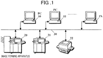
- FIG. 1 is a schematic block diagram illustrating an event notification system in a network according to Embodiment 1 of the present invention.
- (N+1) PCs (personal computers) 10 - 1N as the hosts and image forming apparatuses 20 - 22 as the devices used therein are connected via a network 30.
- FIG. 2 is a schematic block diagram illustrating a hardware configuration of a PC 10 and an image forming apparatus 20, representing the system of FIG. 1 .
- a CPU 41 is connected to PROM 43, DRAM 44, an auxiliary storage device 45, a network interface 46, and a conversational input/output device 47 via an interface 42.
- interfaces 42 of multiple types are represented by a block for the sake of simplicity.
- the PROM 43 is, for example, a flash memory.
- a BIOS Basic Input/Output System
- the DRAM 44 is used as a main storage device.
- An OS Operating System
- various drivers, applications, and data are stored in the auxiliary storage device 45.
- the drivers and applications include those described later in the PC 10 illustrated in FIG. 3 .
- the network interface 46 is connected to the network 30.
- the conversational input/output device 47 is provided with, for example, a keyboard and a pointing device as input devices, and a display device.
- a CPU 21 is connected to PROM 53, DRAM 54, an auxiliary storage device 55, a network interface 56, an operation panel 57, a scanner 58, a printer 59, and a fax modem 5A via an interface 52.
- interfaces 52 of multiple types are represented by a block for the sake of simplicity.
- a BIOS, an OS, various drivers, and various applications for a function as the image forming apparatus are stored in the PROM 53.
- the applications include those described later in the image forming apparatus 20 illustrated in FIG. 3 .
- the DRAM 54 is used as a main storage device.
- Printing data, image data scanned by the scanner 58, an auxiliary file (described later), and facsimile reception data are stored in the auxiliary storage device 55.
- the network interface 56 is connected to the network 30.
- the operation panel 57 is provided with an input unit and a display unit.
- the scanner 58 is used for generating an image file.
- the file is used for printing, facsimile submission, and submission of a file.
- the printer 59 is provided with a printing engine, a paper feeding unit, a conveyance unit, and a paper discharge unit.
- FIG. 1 Other PCs and image forming apparatuses in FIG. 1 have the same configuration as that described above.
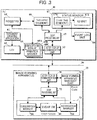
- FIG. 3 is a schematic functional block diagram illustrating the PC 10 and the image forming apparatus 20, representing the system of FIG. 1 .
- Printer drivers 60A, 60B, and 60C installed in the PC 10 correspond respectively to image forming apparatuses 20, 21, and 22 illustrated in FIG. 1 .
- a document is created by a document creating application 61, printing parameters such as paper size, number of copies, post processing, and the like are set through a dialog box, and then printing start instruction is made. And then, the printing data is supplied to a selected printer driver 60A through a GDI (Graphics Device Interface) 62 of the OS. Furthermore, the printing data is converted into PDL (Page Description Language) data that can be interpreted by the image forming device 20, and is transmitted to the image forming device 20 through a communication unit 63 and a network 30.
- PDL Peage Description Language
- the registry 64 is configured such that a value and a data type for an entry (key) are readable/writable by specifying a path in the tree.
- FIG. 4 shows a part of setting data under a printer driver node under a printer node that belongs to a path "HKEY_LOCAL_MACHINE ⁇ SYSTEM ⁇ CurrentControlSet ⁇ Control ⁇ Print ⁇ Pri nters" of the Printers key in the subscribed data for the printer driver 60A subscribed in the registry 64.
- NAME, TYPE, and DATA are names, data types, and values of respective entries.
- StatusMonitor key shows that the data type is a numerical value (REG_DWORD) and the value is 0 (0x00000000). In other words, StatusMonitor key indicates that the status monitor for displaying an event occurring in the image forming apparatus 20 on the PC 10 is set to off.
- IPAddress key shows that the data type is a character string (REG_SG) and the value is "192.168.2.1", indicating that an IP address of the image forming apparatus 20 is 192.168.2.1.
- Notification key shows that the data type is an array of character strings (REG_MULTI_SG) and the value is ⁇ "JobStatus", "1" ⁇ , indicating that a type of an event notification from the image forming apparatus 20 to the PC 10 is "JobStatus” and notification is activated.
- Notification2 key shows that the data type is an array of character strings and the value is ⁇ "PrinterStatus", "0" ⁇ , indicating that a type of an event notification from the image forming apparatus 20 to the PC 10 is "PrinterStatus" and notification is inactivated.
- the printer driver 60A includes an event notification setting unit 65. This allows setting of on/off of the status monitor and activation/inactivation of the notification for each event type, upon setting of the printing parameters. The same applies to the printer drivers 60B and 60C.
- Subscription of an event from the PC 10 to each of the image forming apparatuses 20 to 22, as well as notification of the event therefrom to the PC 10 are performed in conformity to the WS-Eventing specification.
- an event that occurs in the image forming apparatus 20 is notified to the status monitor 67 and displayed, according to the event type and the notification destination address that are subscribed to the image forming apparatus 20 based on the subscription request of event notification (Subscribe request) from the subscriber 66 to the image forming apparatus 20.
- the status monitor 67 is provided with an event sync 670 and an UI unit 671.
- the event sync 670 subscribes a notified event with an event log unit 68 and notifies the UI unit 671 of the event.
- the UI unit 671 displays a content of the notification in a pop-up dialog box. The log can be viewed from an event viewer of the OS.
- the subscriber 66 and the event sync 670 are resident programs, and, in a case in which the OS is Windows (registered trademark), these are Windows service applications. It should be noted that, the notification from the event sync 670 to the UI unit 671 can be in such a mode that the UI unit 671 is indirectly called by an event occurring as a result of subscription of an event from the event sync 670 to the event log unit 68.
- the subscriber 66 and the event sync 670 are started by the OS upon start-up of the OS, and terminated upon shutdown of the OS.
- the printing data is supplied to an image forming apparatus main body part 71 via the network 30 and a TCP/IP protocol stack in the communication unit 70.
- the data is developed to bitmap data and a photosensitive drum is exposed by raster data thereof, thereby forming an electrostatic latent image.
- the image is developed by a toner, transferred to and fused onto paper. The paper is then discharged.
- FIGS. 5A to 5C illustrate respective configuration examples of an event type table 81, an event table 82, and a subscriptions table 83 included in the event database 80.
- the event type table 81 names of event types that can be notified and codes are subscribed in pairs.
- the event table 82 names of events and codes are subscribed in pairs.
- the event code is in four digits. The first two digits thereof represent an event type code and the last two digits represent an event sub-code. More specifically, the event codes 0100 to 0104 indicate that the event type is JobStatusEvent. The event codes 0200 to 0202 indicate that the event type is PrinterStatusEvent.
- the SOAP message of the subscription request of the event notification includes: a ReplyTo address (address of the subscriber 66) including an IP address of a request source; a NotifyTo address (address of the event sync 670) including the IP address of the request source; a To address (address of the subscription manager 730) including an IP address of a request destination; and an event type as a Filter element.
- Default port numbers and paths are used as port numbers and paths in the PC 10 and the image forming apparatus 20 at these addresses. It should be noted that addresses listed in a configuration file (not illustrated) can also be used as these addresses.
- the subscription manager 730 creates Subscription (line) based on the content of the SOAP message as described later, and subscribes with the subscriptions table 83 as shown in FIG. 5C .
- a code thereof is supplied to a notification manager 731 of the event source 73.
- the notification manager 731 performs the following process each time a line having the event type code corresponding to the first two digits of the code is read from the subscriptions table 83.
- the SOAP processing unit 72 converts (serializes) the information into an XML SOAP message, and then submits to the PC 10 via the communication unit 70 and the network 30.
- the information includes a name of an event type corresponding to the event code; a name of an event corresponding to the event code; and time and date of occurrence.
- the message is converted into an object by the SOAP processing unit 69, transmitted to the event sync 670, and subscribed with the event log unit 68.
- the UI unit 671 displays the content thereof in a pop-up dialog box.
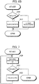
- FIGS. 6A and 6B are flow charts illustrating a subscription request (Subscribe) process of an event notification by the subscriber 66.
- the process is called and executed by the OS upon startup of the OS.
- the process of Steps S0 to S3 is a loop process performed for each of all printer drivers.
- symbols between parentheses are step identification symbols in the drawings.
- Step S1 In a case there is any hit, the processing advances to Step S2; on the other hand, if there is no hit, in other words all printer drivers have been processed, the processing illustrated in FIG. 6A terminates.
- Step S2 If the value of the StatusMonitor key is 1, the processing advances to Step S3; on the other hand, if the value of the StatusMonitor key is 0, the processing returns to Step S0.
- the SOAP message includes an address of the subscriber 66 including an IP address of the PC 10 as a ReplyTo address, and an address of the event sync 670 including said IP address as a NotifyTo address.
- the SOAP message further includes an address of the subscription manager 730 of the image forming apparatus 20, including a value for the IPAddress key included in the key group as a subscription request destination IP address of the event notification, as a To address.
- Step S3 The processing of Step S3 is performed for each key including "Notification”. The processing then returns to Step S0.
- FIG. 6B is a schematic flow chart illustrating processing by the subscription manager 730 with response to the Subscribe request.
- Step S10 If the Subscribe request is a subscription request of the event notification, the processing advances to Step S11; and if not, the processing advances to Step S12.
- the subscription manager 730 refers to the event type table 81, converts the event type included in the request message to a code, generates a subscription ID, obtains current time and date as a time stamp, and sets the activation flag as "1".
- the subscription manager 730 subscribes a line including these values with the subscriptions table 83, replies to the subscriber 66 with a response message including this subscription ID, and terminates the processing illustrated in FIG. 6B .
- the subscriber 66 stores this subscription ID for use in the processing illustrated in FIG. 7 , described later, and the like.
- FIG. 7 is a schematic flow chart illustrating an unsubscription process request of the event notification by the subscriber 66. The process is called and executed by the OS upon shut-down of the OS. The processing of Steps S20 to S22 is loop processing performed for each of all subscriptions stored as described above.
- the subscription manager 730 in response to this request, deletes the subscription from the subscriptions table 83.
- the subscriber 66 pops up the content of the notification via the UI unit 671.
- a user can set the activation flag to "1" and update the time stamp to the current time, by making a Renew request to the subscription manager 730 through the event notification setting unit 65 and the subscriber 66.
- FIG. 1 Other PCs and image forming apparatuses in FIG. 1 are similar to that described above.
- Embodiment 1 provides an effect of automatically making a subscription of an event notification desired by the user with respect to the image forming apparatus, by starting up the subscriber 66 upon start-up of the OS to refer to the registry 64.
- Embodiment 1 provides an effect of allowing notification of an event, which occurs in the image forming apparatus immediately after making the processing request to the image forming apparatus, to the PC.
- Embodiment 1 provides an effect of alleviating a load of the subscription manager 730 while maintaining the above mentioned effect.
- Embodiment 2 upon transition of the PC 10 to a power saving mode, for example a stand-by mode or a sleep mode, the PC 10 performs the processing illustrated in FIG. 7 in response to occurrence of the transition event.
- the PC 10 and the image forming apparatus 20 Upon return from the power saving mode, the PC 10 and the image forming apparatus 20 perform the processing illustrated in FIGS. 6A and 6B , respectively, in response to occurrence of the return event.
- This configuration provides an effect of further alleviating the load of the subscription manager 730 while maintaining effects of Embodiment 1.
- the database used in Step S20 is not limited to the registry 64 and can be other type of database.
- event sync 670 can also be configured to start up upon start-up of the printer driver and shut down upon shutdown on the printer driver.
- a configuration in which the subscriber 66 and the event sync 670 constitute a single resident application and the resident application is started up upon start-up of the OS is accepted.
- the network device is not limited to a multi-function peripheral, and can also be a printer, a scanner, a facsimile machine, or other devices.
Description
- The present invention relates to a network-based event notification system in which a host and a plurality of devices are connected via the network, and more specifically to an event notification system in a network that notifies the host of an event that occurs in the device, according to a request from the host to the device, based on a type of the event subscribed and a notification destination address.
- A specification for notifying a host of an event that occurs in a network device such as an image forming apparatus via a network is prescribed as WS-Eventing. According to this, it is sufficient to notify only a host that has made a subscription request of an event of a type (Filter element) relating to the request, and there is no need for going through a dedicated management device for notification of an event.
- Conventionally, after start-up of a printer driver, the printer driver was making the subscription request (FIG. 16 Japanese Unexamined Patent Application Publication No.
2009-230477 - Furthermore,
EP 1 895 401 A1 - However, since an image forming apparatus is required to process a notification reservation subscription request for each of a plurality of devices and notify each event that occurs based on the subscription, load may be concentrated. As a result, if the printer driver makes the subscription request before starting printing and submits printing data to the image forming apparatus after receiving an acknowledge response thereto, completion of a printing job may be delayed.
- Given this, it is configured in such a way that submission of the printing data and start-up of a status monitor take place simultaneously, and the status monitor performs the subscription request.
- Nevertheless, in a case in which the printing data is small or an error occurs in the image forming apparatus immediately after a printing start instruction, a printing process may be completed before completion of start-up of the status monitor or an error may occur, preventing reception of an event notification of completion of printing or occurrence of an error. Such a problem applies similarly to other network devices.
- The objective of the present invention is to provide an event notification system in a network that allows notification of an event, which occurs in a device immediately after making a processing request to the device, to a host.
- The present invention is an event notification system as in claims 1-3.
-
-
FIG. 1 is a schematic block diagram illustrating an event notification system in a network according toEmbodiment 1 of the present invention; -
FIG. 2 is a schematic block diagram illustrating a hardware configuration of a PC and an image forming apparatus, representing the system ofFIG. 1 ; -
FIG. 3 is a schematic functional block diagram illustrating a PC and an image forming apparatus, representing the system ofFIG. 1 ; -
FIG. 4 is an explanatory diagram illustrating a part of setting data of a printer driver subscribed in a registry; -
FIG. 5A is a diagram illustrating a configuration example of an event type table included in the event database ofFIG. 3 ; -
FIG. 5B is a diagram illustrating a configuration example of an event table included in the event database ofFIG. 3 ; -
FIG. 5C is a diagram illustrating a configuration example of a subscriptions table included in the event database ofFIG. 3 ; -
FIG. 6A is a flow chart illustrating a subscription request process of an event notification by the subscriber inFIG. 3 ; -
FIG. 6B is a flow chart illustrating a subscription request process of an event notification by the subscriber inFIG. 3 ; and -
FIG. 7 is a flow chart illustrating an unsubscription process request of an event notification by the subscriber inFIG. 3 . -
- 10 - 1N PC
- 20 -22 Image forming apparatus
- 30 Network
- 41, 51 CPU
- 42, 52 Interface
- 43, 53 PROM
- 44, 54 DRAM
- 45, 55 Auxiliary storage device
- 46, 56 Network interface
- 47 Conversational input/output device
- 57 Operation panel
- 58 Scanner
- 59 Printer
- 5A Fax modem
- 60A - 60C Printer driver
- 61 Document creating application
- 62 GDI
- 63, 70 Communication unit
- 64 Registry
- 65 Event notification setting unit
- 66 Subscriber
- 67 Status monitor
- 670 Event sync
- 671 UI unit
- 68 Event log unit
- 69, 72 SOAP processing unit
- 71 Image forming apparatus main body part
- 73 Event source
- 730 Subscription manager
- 731 Notification manager
- 80 Event database
- 81 Event type table
- 82 Event table
- 83 Subscriptions table
-
FIG. 1 is a schematic block diagram illustrating an event notification system in a network according toEmbodiment 1 of the present invention. - In this system, (N+1) PCs (personal computers) 10 - 1N as the hosts and image forming apparatuses 20 - 22 as the devices used therein are connected via a
network 30. -
FIG. 2 is a schematic block diagram illustrating a hardware configuration of aPC 10 and animage forming apparatus 20, representing the system ofFIG. 1 . - In the
PC 10, aCPU 41 is connected toPROM 43,DRAM 44, anauxiliary storage device 45, anetwork interface 46, and a conversational input/output device 47 via aninterface 42. InFIG. 2 , interfaces 42 of multiple types are represented by a block for the sake of simplicity. - The
PROM 43 is, for example, a flash memory. A BIOS (Basic Input/Output System) is stored in thePROM 43. TheDRAM 44 is used as a main storage device. An OS (Operating System), various drivers, applications, and data are stored in theauxiliary storage device 45. The drivers and applications include those described later in thePC 10 illustrated inFIG. 3 . Thenetwork interface 46 is connected to thenetwork 30. The conversational input/output device 47 is provided with, for example, a keyboard and a pointing device as input devices, and a display device. - In the
image forming apparatus 20, aCPU 21 is connected toPROM 53,DRAM 54, anauxiliary storage device 55, anetwork interface 56, anoperation panel 57, ascanner 58, aprinter 59, and a fax modem 5A via aninterface 52. InFIG. 2 , interfaces 52 of multiple types are represented by a block for the sake of simplicity. - A BIOS, an OS, various drivers, and various applications for a function as the image forming apparatus are stored in the
PROM 53. The applications include those described later in theimage forming apparatus 20 illustrated inFIG. 3 . TheDRAM 54 is used as a main storage device. Printing data, image data scanned by thescanner 58, an auxiliary file (described later), and facsimile reception data are stored in theauxiliary storage device 55. Thenetwork interface 56 is connected to thenetwork 30. Theoperation panel 57 is provided with an input unit and a display unit. Thescanner 58 is used for generating an image file. The file is used for printing, facsimile submission, and submission of a file. Theprinter 59 is provided with a printing engine, a paper feeding unit, a conveyance unit, and a paper discharge unit. - Other PCs and image forming apparatuses in
FIG. 1 have the same configuration as that described above. -
FIG. 3 is a schematic functional block diagram illustrating thePC 10 and theimage forming apparatus 20, representing the system ofFIG. 1 . -
Printer drivers PC 10 correspond respectively to image formingapparatuses FIG. 1 . A document is created by adocument creating application 61, printing parameters such as paper size, number of copies, post processing, and the like are set through a dialog box, and then printing start instruction is made. And then, the printing data is supplied to a selectedprinter driver 60A through a GDI (Graphics Device Interface) 62 of the OS. Furthermore, the printing data is converted into PDL (Page Description Language) data that can be interpreted by theimage forming device 20, and is transmitted to theimage forming device 20 through acommunication unit 63 and anetwork 30. - Setting information of the OS, the device drivers, and the applications is subscribed in the
registry 64 as the database in a tree format. Theregistry 64 is configured such that a value and a data type for an entry (key) are readable/writable by specifying a path in the tree. -
FIG. 4 shows a part of setting data under a printer driver node under a printer node that belongs to a path "HKEY_LOCAL_MACHINE¥SYSTEM¥CurrentControlSet¥Control¥Print¥Pri nters" of the Printers key in the subscribed data for theprinter driver 60A subscribed in theregistry 64. InFIG. 4 , NAME, TYPE, and DATA are names, data types, and values of respective entries. - For example, StatusMonitor key shows that the data type is a numerical value (REG_DWORD) and the value is 0 (0x00000000). In other words, StatusMonitor key indicates that the status monitor for displaying an event occurring in the
image forming apparatus 20 on thePC 10 is set to off. IPAddress key shows that the data type is a character string (REG_SG) and the value is "192.168.2.1", indicating that an IP address of theimage forming apparatus 20 is 192.168.2.1. Notification key shows that the data type is an array of character strings (REG_MULTI_SG) and the value is {"JobStatus", "1"}, indicating that a type of an event notification from theimage forming apparatus 20 to thePC 10 is "JobStatus" and notification is activated. Similarly,Notification2 key shows that the data type is an array of character strings and the value is {"PrinterStatus", "0"}, indicating that a type of an event notification from theimage forming apparatus 20 to thePC 10 is "PrinterStatus" and notification is inactivated. - The
printer driver 60A includes an eventnotification setting unit 65. This allows setting of on/off of the status monitor and activation/inactivation of the notification for each event type, upon setting of the printing parameters. The same applies to theprinter drivers - Subscription of an event from the
PC 10 to each of theimage forming apparatuses 20 to 22, as well as notification of the event therefrom to thePC 10 are performed in conformity to the WS-Eventing specification. In other words, an event that occurs in theimage forming apparatus 20 is notified to thestatus monitor 67 and displayed, according to the event type and the notification destination address that are subscribed to theimage forming apparatus 20 based on the subscription request of event notification (Subscribe request) from thesubscriber 66 to theimage forming apparatus 20. - The status monitor 67 is provided with an
event sync 670 and an UI unit 671. Theevent sync 670 subscribes a notified event with anevent log unit 68 and notifies the UI unit 671 of the event. In response to this, the UI unit 671 displays a content of the notification in a pop-up dialog box. The log can be viewed from an event viewer of the OS. - The
subscriber 66 and theevent sync 670 are resident programs, and, in a case in which the OS is Windows (registered trademark), these are Windows service applications. It should be noted that, the notification from theevent sync 670 to the UI unit 671 can be in such a mode that the UI unit 671 is indirectly called by an event occurring as a result of subscription of an event from theevent sync 670 to theevent log unit 68. - The
subscriber 66 and theevent sync 670 are started by the OS upon start-up of the OS, and terminated upon shutdown of the OS. - The
subscriber 66 calls a Web service method with respect to a SOAP proxy in aSOAP processing unit 69. And then, the content thereof is XML serialized by the proxy and converted into a SOAP message, and submitted to theimage forming apparatus 20 via an HTTP/TCP/IP protocol stack in thecommunication unit 63. The event notification message from theimage forming apparatus 20 is XML deserialized by a SOAP listener in theSOAP processing unit 69 via thenetwork 30 and thecommunication unit 63, and then transmitted as an event notification object to theevent sync 670. - In the
image forming apparatus 20, the printing data is supplied to an image forming apparatusmain body part 71 via thenetwork 30 and a TCP/IP protocol stack in thecommunication unit 70. The data is developed to bitmap data and a photosensitive drum is exposed by raster data thereof, thereby forming an electrostatic latent image. The image is developed by a toner, transferred to and fused onto paper. The paper is then discharged. - On the other hand, the SOAP message of the subscription request of an event notification from the
PC 10 is supplied to aSOAP processing unit 72 via thenetwork 30 and the HTTP/TCP/IP protocol stack in thecommunication unit 70, and then XML deserialized. The SOAP message is supplied, as a subscription request object of the event notification, to asubscription manager 730 of anevent source 73. In response to this, thesubscription manager 730 subscribes event notification information with anevent database 80 as described later. -
FIGS. 5A to 5C illustrate respective configuration examples of an event type table 81, an event table 82, and a subscriptions table 83 included in theevent database 80. In the event type table 81, names of event types that can be notified and codes are subscribed in pairs. In the event table 82, names of events and codes are subscribed in pairs. In this example, the event code is in four digits. The first two digits thereof represent an event type code and the last two digits represent an event sub-code. More specifically, theevent codes 0100 to 0104 indicate that the event type is JobStatusEvent. Theevent codes 0200 to 0202 indicate that the event type is PrinterStatusEvent. - The SOAP message of the subscription request of the event notification includes: a ReplyTo address (address of the subscriber 66) including an IP address of a request source; a NotifyTo address (address of the event sync 670) including the IP address of the request source; a To address (address of the subscription manager 730) including an IP address of a request destination; and an event type as a Filter element. Default port numbers and paths are used as port numbers and paths in the
PC 10 and theimage forming apparatus 20 at these addresses. It should be noted that addresses listed in a configuration file (not illustrated) can also be used as these addresses. - The
subscription manager 730 creates Subscription (line) based on the content of the SOAP message as described later, and subscribes with the subscriptions table 83 as shown inFIG. 5C . - When an event occurs in the image forming apparatus
main body part 71, a code thereof is supplied to anotification manager 731 of theevent source 73. In response to this, thenotification manager 731 performs the following process each time a line having the event type code corresponding to the first two digits of the code is read from the subscriptions table 83. - (1) In a case in which an activation flag is "1" and a difference between the current time and date and a timestamp included in this line is smaller than a valid period, the
notification manager 731 supplies information for notifying theevent sync 670 in a host having the IP address included in this line of occurrence of an event corresponding to the code, to theSOAP processing unit 72. - (2) In a case in which the activation flag is "1" and the difference between the current time and date and the timestamp included in this line is equal to or greater than the valid period, the activation flag is changed to "0" via the
subscription manager 730 and thenotification manager 731 supplies information for notifying thesubscriber 66 in a host having the IP address included in this line of the expiration of the valid period, to theSOAP processing unit 72. - (3) In a case in which the activation flag is "0", the
notification manager 731 terminates this processing for subscription. - After the above process (1), the
SOAP processing unit 72 converts (serializes) the information into an XML SOAP message, and then submits to thePC 10 via thecommunication unit 70 and thenetwork 30. The information includes a name of an event type corresponding to the event code; a name of an event corresponding to the event code; and time and date of occurrence. - The message is converted into an object by the
SOAP processing unit 69, transmitted to theevent sync 670, and subscribed with theevent log unit 68. The UI unit 671 displays the content thereof in a pop-up dialog box. -
FIGS. 6A and6B are flow charts illustrating a subscription request (Subscribe) process of an event notification by thesubscriber 66. The process is called and executed by the OS upon startup of the OS. The process of Steps S0 to S3 is a loop process performed for each of all printer drivers. Hereafter, symbols between parentheses are step identification symbols in the drawings. - (S0) From all the printer driver setting information subscribed in the
registry 64, for example keys in a key group relating to a driver of each printer under the path of the Printers key described above are scanned to obtain an entry of the StatusMonitor key. It should be noted that, if a relative path from the printer driver key is known, a path of the StatusMonitor key can be directly specified each time the printer driver key is found, to obtain the entry thereof. - (S1) In a case there is any hit, the processing advances to Step S2; on the other hand, if there is no hit, in other words all printer drivers have been processed, the processing illustrated in
FIG. 6A terminates. - (S2) If the value of the StatusMonitor key is 1, the processing advances to Step S3; on the other hand, if the value of the StatusMonitor key is 0, the processing returns to Step S0.
- (S3) Among the key group under the printer driver key to which the StatusMonitor key belongs, an entry for a key including "Notification" is obtained. If the value for activation/inactivation of the notification indicates activation, in other words the value for an element with an
index 1 in the array is 1, a character string of an element with anindex 0 is obtained as the event type. A SOAP message of the Subscribe request including said type as a value for the Filter element is submitted to thesubscription manager 730. - The SOAP message includes an address of the
subscriber 66 including an IP address of thePC 10 as a ReplyTo address, and an address of theevent sync 670 including said IP address as a NotifyTo address. The SOAP message further includes an address of thesubscription manager 730 of theimage forming apparatus 20, including a value for the IPAddress key included in the key group as a subscription request destination IP address of the event notification, as a To address. - The processing of Step S3 is performed for each key including "Notification". The processing then returns to Step S0.
-
FIG. 6B is a schematic flow chart illustrating processing by thesubscription manager 730 with response to the Subscribe request. - (S10) If the Subscribe request is a subscription request of the event notification, the processing advances to Step S11; and if not, the processing advances to Step S12.
- (S11) As described above, the
subscription manager 730 refers to the event type table 81, converts the event type included in the request message to a code, generates a subscription ID, obtains current time and date as a time stamp, and sets the activation flag as "1". In addition, thesubscription manager 730 subscribes a line including these values with the subscriptions table 83, replies to thesubscriber 66 with a response message including this subscription ID, and terminates the processing illustrated inFIG. 6B . - The
subscriber 66 stores this subscription ID for use in the processing illustrated inFIG. 7 , described later, and the like. - (S12) Other processing is performed according to the request, and the processing illustrated in
FIG. 6B is terminated. -
FIG. 7 is a schematic flow chart illustrating an unsubscription process request of the event notification by thesubscriber 66. The process is called and executed by the OS upon shut-down of the OS. The processing of Steps S20 to S22 is loop processing performed for each of all subscriptions stored as described above. - (S20) One of all subscription IDs stored as described above is read.
- (S21) If there is nothing to read, the processing illustrated in FIG. 9 is terminated; if not, the processing advances to Step S22.
- (S22) A SOAP message of the unsubscribe request of the event notification (Unsubscribe request) including this subscription ID is submitted to the
subscription manager 730, the subscription ID is deleted from thesubscriber 66, and the processing returns to Step S20. - The
subscription manager 730, in response to this request, deletes the subscription from the subscriptions table 83. - It should be noted that, when the notification of the above (2) is transmitted to the
subscriber 66, thesubscriber 66 pops up the content of the notification via the UI unit 671. A user can set the activation flag to "1" and update the time stamp to the current time, by making a Renew request to thesubscription manager 730 through the eventnotification setting unit 65 and thesubscriber 66. - Other PCs and image forming apparatuses in
FIG. 1 are similar to that described above. -
Embodiment 1 provides an effect of automatically making a subscription of an event notification desired by the user with respect to the image forming apparatus, by starting up thesubscriber 66 upon start-up of the OS to refer to theregistry 64. In addition,Embodiment 1 provides an effect of allowing notification of an event, which occurs in the image forming apparatus immediately after making the processing request to the image forming apparatus, to the PC. - In addition, upon shutdown of the OS, the
subscriber 66 makes the unsubscription request of the event notification with respect to the image forming apparatus to which the notification subscribe request has been made. As a result,Embodiment 1 provides an effect of alleviating a load of thesubscription manager 730 while maintaining the above mentioned effect. - In
Embodiment 2, upon transition of thePC 10 to a power saving mode, for example a stand-by mode or a sleep mode, thePC 10 performs the processing illustrated inFIG. 7 in response to occurrence of the transition event. Upon return from the power saving mode, thePC 10 and theimage forming apparatus 20 perform the processing illustrated inFIGS. 6A and6B , respectively, in response to occurrence of the return event. - This configuration provides an effect of further alleviating the load of the
subscription manager 730 while maintaining effects ofEmbodiment 1. - Preferred embodiments of the present invention have been described above; however, the invention is defined by the claimed subject-matter and the embodiments can be modified.
- For example, the database used in Step S20 is not limited to the
registry 64 and can be other type of database. - In addition, the
event sync 670 can also be configured to start up upon start-up of the printer driver and shut down upon shutdown on the printer driver. In addition, a configuration in which thesubscriber 66 and theevent sync 670 constitute a single resident application and the resident application is started up upon start-up of the OS is accepted. - Furthermore, the network device is not limited to a multi-function peripheral, and can also be a printer, a scanner, a facsimile machine, or other devices.
Claims (3)
- A network-based event notification system comprising:
a plurality of image forming apparatuses (20, 21, 22) connected to a network (30):a host, which includes a plurality of printer drivers (60A, 60B, 60C) corresponding to the plurality of image forming apparatuses (20, 21, 22) connected to the network (30), the plurality of printer drivers (60A, 60B, 60C) being installed in a storage unit included in the host,wherein the event notification system notifies the host of an event based on a request from the host to an image forming apparatus (20, 21, 22), according to a type of the event and a notification destination address that are subscribed in the image forming apparatus (20, 21, 22),the storage unit included in the host comprises:a status monitor (67);a subscriber (66) that is a resident program started by an operating system upon start-up of the operating system and terminated upon shutdown of the operating system; anda registry (64) serving as a database, in which setting information of each of the printer drivers (60A, 60B, 60C) is subscribed in a tree format and a value and a data type for a key are set by specifying a path in the tree format,wherein the registry (64) includes 1) a status monitor key including on/off information of the status monitor for each of the plurality of printer drivers (60A, 60B, 60C), 2) an IP address key including an IP address of the image forming apparatus (20, 21, 22), and 3) a notification key including activation/inactivation information of notification for the type of the event,wherein the subscriber (66) is called and executed upon the operating system start-up and in a subscription request process of an event notification: 1) obtains the values and the data type for the key from all the printer drivers setting information subscribed in the registry (64); 2) sends a subscription request to the image forming apparatus (20, 21, 22) corresponding to the printer driver (60A, 60B, 60C) for which the on/off information of the status monitor (67) included in the status monitor key indicates "on" and the activation/inactivation information of notification for the type of the event included in the notification key indicates "activation" including the data type for an event notification, an IP address of the subscriber (66) and an IP address of the status monitor (67) and a value for the IP address key as a request destination IP address of the event notification included in the IP address key,wherein the value and the data type for the key are set via the printer driver (60A, 60B, 60C), upon setting printing parameters,wherein the status monitor (67) receives the notification of the event from the image forming apparatus (20, 21, 22), and- displays a content of the notification of the event wherein the subscriber (66) makes an unsubscription of the request notifying the host of the event to each of the image forming apparatuses (20, 21, 22) for which the notification of the event is subscribed, upon a shut-down of the operating system, andwherein the subscriber (66) makes the subscription of the request notifying the host of the event to the image forming apparatus (20, 21, 22) and the status monitor (67) receives the notification of the event from the image forming apparatus (20, 21, 22) according to a WS-Eventing specification. - The event notification system according to claim 1, wherein the subscriber (66) makes an unsubscription of the request notifying the host of the event to each of the image forming apparatuses (20, 21, 22) for which the notification of the event is subscribed, upon transition of the host to a power saving mode, and
wherein the subscriber (66) makes the subscription of the request notifying the host of the event to the image forming apparatus (20, 21, 22) to which the unsubscription request has been made, upon return from the power saving mode. - The event notification system according to claim 1, wherein the image forming apparatus (20, 21, 22) comprises at least one of a printer, a scanner, a facsimile device, and a multi-function peripheral.
Applications Claiming Priority (2)
| Application Number | Priority Date | Filing Date | Title |
|---|---|---|---|
| JP2012016358A JP5378554B2 (en) | 2012-01-30 | 2012-01-30 | Network event notification system |
| PCT/JP2013/051920 WO2013115188A1 (en) | 2012-01-30 | 2013-01-29 | Network-based event notification system |
Publications (3)
| Publication Number | Publication Date |
|---|---|
| EP2811394A1 EP2811394A1 (en) | 2014-12-10 |
| EP2811394A4 EP2811394A4 (en) | 2015-10-21 |
| EP2811394B1 true EP2811394B1 (en) | 2019-07-03 |
Family
ID=48905223
Family Applications (1)
| Application Number | Title | Priority Date | Filing Date |
|---|---|---|---|
| EP13743696.0A Active EP2811394B1 (en) | 2012-01-30 | 2013-01-29 | Network-based event notification system |
Country Status (5)
| Country | Link |
|---|---|
| US (1) | US9367274B2 (en) |
| EP (1) | EP2811394B1 (en) |
| JP (1) | JP5378554B2 (en) |
| CN (1) | CN104094216B (en) |
| WO (1) | WO2013115188A1 (en) |
Families Citing this family (7)
| Publication number | Priority date | Publication date | Assignee | Title |
|---|---|---|---|---|
| CN102198658A (en) | 2010-03-25 | 2011-09-28 | 鸿富锦精密工业(深圳)有限公司 | Robot arm assembly |
| JP5968930B2 (en) | 2014-02-19 | 2016-08-10 | 京セラドキュメントソリューションズ株式会社 | Image forming apparatus and event notification system |
| EP2998865B1 (en) * | 2014-09-19 | 2021-08-18 | Canon Europa N.V. | Method of submitting captured data to an analytics service |
| JP2016159499A (en) * | 2015-02-27 | 2016-09-05 | 京セラドキュメントソリューションズ株式会社 | Function providing system and function relay program |
| JP6577727B2 (en) * | 2015-03-25 | 2019-09-18 | キヤノン株式会社 | Information processing apparatus, information processing system, and information processing method |
| CN107172032B (en) * | 2017-05-10 | 2020-07-21 | 北京邮电大学 | Communication method based on southbound interface protocol and related equipment |
| CN109753399B (en) * | 2017-11-01 | 2022-05-13 | 中国石油化工股份有限公司 | Automatic notification and response method for system unit state change |
Family Cites Families (13)
| Publication number | Priority date | Publication date | Assignee | Title |
|---|---|---|---|---|
| JP3320342B2 (en) * | 1997-09-12 | 2002-09-03 | インターナショナル・ビジネス・マシーンズ・コーポレーション | Method for causing printer system to execute printing, print execution method, computer, and printer system |
| US7107497B2 (en) * | 2002-09-30 | 2006-09-12 | Sun Microsystems, Inc. | Method and system for event publication and subscription with an event channel from user level and kernel level |
| US7028229B2 (en) * | 2002-09-30 | 2006-04-11 | Sun Microsystems, Inc. | Kernel event subscription and publication system and method |
| JP2004185217A (en) * | 2002-12-02 | 2004-07-02 | Canon Inc | Device management method |
| JP4868799B2 (en) * | 2005-08-31 | 2012-02-01 | キヤノン株式会社 | Server apparatus and event notification method |
| JP5159071B2 (en) * | 2006-09-01 | 2013-03-06 | キヤノン株式会社 | COMMUNICATION SYSTEM, COMMUNICATION DEVICE, AND ITS CONTROL METHOD |
| JP4944593B2 (en) | 2006-12-21 | 2012-06-06 | キヤノン株式会社 | Image forming apparatus, control method therefor, and computer program |
| JP4930051B2 (en) * | 2006-12-28 | 2012-05-09 | ブラザー工業株式会社 | Status monitor program |
| JP4274259B2 (en) * | 2007-02-28 | 2009-06-03 | コニカミノルタビジネステクノロジーズ株式会社 | Push-type pull printing system, pull printing method, and image forming apparatus |
| JP4850761B2 (en) * | 2007-03-16 | 2012-01-11 | 株式会社リコー | Event notification device and event notification method |
| JP5056200B2 (en) * | 2007-06-26 | 2012-10-24 | コニカミノルタビジネステクノロジーズ株式会社 | Event notification method, control program, and control apparatus |
| JP4987770B2 (en) * | 2008-03-24 | 2012-07-25 | 株式会社リコー | Event notification device, event notification method, and event notification program |
| US8355170B2 (en) * | 2010-07-26 | 2013-01-15 | Ricoh Company, Ltd | Methods and systems to provide scan services to an image forming device |
-
2012
- 2012-01-30 JP JP2012016358A patent/JP5378554B2/en not_active Expired - Fee Related
-
2013
- 2013-01-29 WO PCT/JP2013/051920 patent/WO2013115188A1/en active Application Filing
- 2013-01-29 US US14/375,031 patent/US9367274B2/en active Active
- 2013-01-29 CN CN201380006971.0A patent/CN104094216B/en not_active Expired - Fee Related
- 2013-01-29 EP EP13743696.0A patent/EP2811394B1/en active Active
Non-Patent Citations (1)
| Title |
|---|
| None * |
Also Published As
| Publication number | Publication date |
|---|---|
| JP5378554B2 (en) | 2013-12-25 |
| WO2013115188A1 (en) | 2013-08-08 |
| US20150043031A1 (en) | 2015-02-12 |
| EP2811394A1 (en) | 2014-12-10 |
| CN104094216A (en) | 2014-10-08 |
| EP2811394A4 (en) | 2015-10-21 |
| JP2013156809A (en) | 2013-08-15 |
| US9367274B2 (en) | 2016-06-14 |
| CN104094216B (en) | 2017-05-24 |
Similar Documents
| Publication | Publication Date | Title |
|---|---|---|
| EP2811394B1 (en) | Network-based event notification system | |
| US8854677B2 (en) | Push-notification system and method for notifying event message to mobile terminal apparatus | |
| EP2620864B1 (en) | An event notification system in which a terminal is notified of events generated in devices via a network | |
| US7359081B2 (en) | Information processing apparatus, distributed printing method, and storage medium | |
| US8780388B2 (en) | Printing apparatus, server, printing system, control method for printing apparatus, and storage medium storing control program therefor | |
| US8797592B2 (en) | System, method, and computer-readable recording medium for executing printing with image forming apparatus | |
| US8020170B2 (en) | Information processing apparatus, method of operating it, and computer readable information recording medium | |
| GB2359392A (en) | Print job processing in a printer network using user selected job attributes | |
| US8400650B2 (en) | Network printer and network printing method of restricting host from using network printer | |
| US8605316B2 (en) | Information processing apparatus and control method thereof, and storage medium | |
| JP2011034562A (en) | Print system | |
| EP2426595A2 (en) | Image forming system and storage medium | |
| US8922823B2 (en) | Information processing apparatus and storage medium with the function of adding a cover letter to a print job | |
| JP5450678B2 (en) | Network event notification system | |
| JP2014041599A (en) | Program, information processing apparatus, and system | |
| US9025190B2 (en) | Box print realized by image forming apparatus having no auxiliary storage device | |
| EP2750023B1 (en) | Box print realized by image forming apparatus having no auxiliary storage device | |
| JP5378553B2 (en) | Network event notification system | |
| JP2021043547A (en) | Information processing device and control method for information processing device, and program | |
| JP5937030B2 (en) | Image forming system | |
| JPH118727A (en) | Image processor and information processing system | |
| JP6454985B2 (en) | Program and information processing apparatus | |
| JP2003162386A (en) | Job control system | |
| JP2008273118A (en) | Image forming apparatus, printing control method, and printing control program |
Legal Events
| Date | Code | Title | Description |
|---|---|---|---|
| PUAI | Public reference made under article 153(3) epc to a published international application that has entered the european phase |
Free format text: ORIGINAL CODE: 0009012 |
|
| 17P | Request for examination filed |
Effective date: 20140818 |
|
| AK | Designated contracting states |
Kind code of ref document: A1 Designated state(s): AL AT BE BG CH CY CZ DE DK EE ES FI FR GB GR HR HU IE IS IT LI LT LU LV MC MK MT NL NO PL PT RO RS SE SI SK SM TR |
|
| AX | Request for extension of the european patent |
Extension state: BA ME |
|
| DAX | Request for extension of the european patent (deleted) | ||
| RA4 | Supplementary search report drawn up and despatched (corrected) |
Effective date: 20150922 |
|
| RIC1 | Information provided on ipc code assigned before grant |
Ipc: G06F 11/30 20060101ALI20150916BHEP Ipc: G06F 13/00 20060101ALI20150916BHEP Ipc: G06F 3/12 20060101AFI20150916BHEP Ipc: G06F 1/32 20060101ALI20150916BHEP Ipc: G06F 11/32 20060101ALI20150916BHEP Ipc: B41J 29/38 20060101ALI20150916BHEP |
|
| STAA | Information on the status of an ep patent application or granted ep patent |
Free format text: STATUS: EXAMINATION IS IN PROGRESS |
|
| 17Q | First examination report despatched |
Effective date: 20180717 |
|
| GRAP | Despatch of communication of intention to grant a patent |
Free format text: ORIGINAL CODE: EPIDOSNIGR1 |
|
| STAA | Information on the status of an ep patent application or granted ep patent |
Free format text: STATUS: GRANT OF PATENT IS INTENDED |
|
| INTG | Intention to grant announced |
Effective date: 20190321 |
|
| GRAS | Grant fee paid |
Free format text: ORIGINAL CODE: EPIDOSNIGR3 |
|
| GRAA | (expected) grant |
Free format text: ORIGINAL CODE: 0009210 |
|
| STAA | Information on the status of an ep patent application or granted ep patent |
Free format text: STATUS: THE PATENT HAS BEEN GRANTED |
|
| AK | Designated contracting states |
Kind code of ref document: B1 Designated state(s): AL AT BE BG CH CY CZ DE DK EE ES FI FR GB GR HR HU IE IS IT LI LT LU LV MC MK MT NL NO PL PT RO RS SE SI SK SM TR |
|
| REG | Reference to a national code |
Ref country code: GB Ref legal event code: FG4D |
|
| REG | Reference to a national code |
Ref country code: CH Ref legal event code: EP Ref country code: AT Ref legal event code: REF Ref document number: 1151798 Country of ref document: AT Kind code of ref document: T Effective date: 20190715 |
|
| REG | Reference to a national code |
Ref country code: IE Ref legal event code: FG4D |
|
| REG | Reference to a national code |
Ref country code: DE Ref legal event code: R096 Ref document number: 602013057394 Country of ref document: DE |
|
| REG | Reference to a national code |
Ref country code: NL Ref legal event code: MP Effective date: 20190703 |
|
| REG | Reference to a national code |
Ref country code: LT Ref legal event code: MG4D |
|
| REG | Reference to a national code |
Ref country code: AT Ref legal event code: MK05 Ref document number: 1151798 Country of ref document: AT Kind code of ref document: T Effective date: 20190703 |
|
| PG25 | Lapsed in a contracting state [announced via postgrant information from national office to epo] |
Ref country code: NO Free format text: LAPSE BECAUSE OF FAILURE TO SUBMIT A TRANSLATION OF THE DESCRIPTION OR TO PAY THE FEE WITHIN THE PRESCRIBED TIME-LIMIT Effective date: 20191003 Ref country code: SE Free format text: LAPSE BECAUSE OF FAILURE TO SUBMIT A TRANSLATION OF THE DESCRIPTION OR TO PAY THE FEE WITHIN THE PRESCRIBED TIME-LIMIT Effective date: 20190703 Ref country code: HR Free format text: LAPSE BECAUSE OF FAILURE TO SUBMIT A TRANSLATION OF THE DESCRIPTION OR TO PAY THE FEE WITHIN THE PRESCRIBED TIME-LIMIT Effective date: 20190703 Ref country code: FI Free format text: LAPSE BECAUSE OF FAILURE TO SUBMIT A TRANSLATION OF THE DESCRIPTION OR TO PAY THE FEE WITHIN THE PRESCRIBED TIME-LIMIT Effective date: 20190703 Ref country code: LT Free format text: LAPSE BECAUSE OF FAILURE TO SUBMIT A TRANSLATION OF THE DESCRIPTION OR TO PAY THE FEE WITHIN THE PRESCRIBED TIME-LIMIT Effective date: 20190703 Ref country code: AT Free format text: LAPSE BECAUSE OF FAILURE TO SUBMIT A TRANSLATION OF THE DESCRIPTION OR TO PAY THE FEE WITHIN THE PRESCRIBED TIME-LIMIT Effective date: 20190703 Ref country code: PT Free format text: LAPSE BECAUSE OF FAILURE TO SUBMIT A TRANSLATION OF THE DESCRIPTION OR TO PAY THE FEE WITHIN THE PRESCRIBED TIME-LIMIT Effective date: 20191104 Ref country code: BG Free format text: LAPSE BECAUSE OF FAILURE TO SUBMIT A TRANSLATION OF THE DESCRIPTION OR TO PAY THE FEE WITHIN THE PRESCRIBED TIME-LIMIT Effective date: 20191003 Ref country code: CZ Free format text: LAPSE BECAUSE OF FAILURE TO SUBMIT A TRANSLATION OF THE DESCRIPTION OR TO PAY THE FEE WITHIN THE PRESCRIBED TIME-LIMIT Effective date: 20190703 Ref country code: NL Free format text: LAPSE BECAUSE OF FAILURE TO SUBMIT A TRANSLATION OF THE DESCRIPTION OR TO PAY THE FEE WITHIN THE PRESCRIBED TIME-LIMIT Effective date: 20190703 |
|
| PG25 | Lapsed in a contracting state [announced via postgrant information from national office to epo] |
Ref country code: ES Free format text: LAPSE BECAUSE OF FAILURE TO SUBMIT A TRANSLATION OF THE DESCRIPTION OR TO PAY THE FEE WITHIN THE PRESCRIBED TIME-LIMIT Effective date: 20190703 Ref country code: LV Free format text: LAPSE BECAUSE OF FAILURE TO SUBMIT A TRANSLATION OF THE DESCRIPTION OR TO PAY THE FEE WITHIN THE PRESCRIBED TIME-LIMIT Effective date: 20190703 Ref country code: AL Free format text: LAPSE BECAUSE OF FAILURE TO SUBMIT A TRANSLATION OF THE DESCRIPTION OR TO PAY THE FEE WITHIN THE PRESCRIBED TIME-LIMIT Effective date: 20190703 Ref country code: RS Free format text: LAPSE BECAUSE OF FAILURE TO SUBMIT A TRANSLATION OF THE DESCRIPTION OR TO PAY THE FEE WITHIN THE PRESCRIBED TIME-LIMIT Effective date: 20190703 Ref country code: IS Free format text: LAPSE BECAUSE OF FAILURE TO SUBMIT A TRANSLATION OF THE DESCRIPTION OR TO PAY THE FEE WITHIN THE PRESCRIBED TIME-LIMIT Effective date: 20191103 Ref country code: GR Free format text: LAPSE BECAUSE OF FAILURE TO SUBMIT A TRANSLATION OF THE DESCRIPTION OR TO PAY THE FEE WITHIN THE PRESCRIBED TIME-LIMIT Effective date: 20191004 |
|
| PG25 | Lapsed in a contracting state [announced via postgrant information from national office to epo] |
Ref country code: TR Free format text: LAPSE BECAUSE OF FAILURE TO SUBMIT A TRANSLATION OF THE DESCRIPTION OR TO PAY THE FEE WITHIN THE PRESCRIBED TIME-LIMIT Effective date: 20190703 |
|
| PG25 | Lapsed in a contracting state [announced via postgrant information from national office to epo] |
Ref country code: IT Free format text: LAPSE BECAUSE OF FAILURE TO SUBMIT A TRANSLATION OF THE DESCRIPTION OR TO PAY THE FEE WITHIN THE PRESCRIBED TIME-LIMIT Effective date: 20190703 Ref country code: RO Free format text: LAPSE BECAUSE OF FAILURE TO SUBMIT A TRANSLATION OF THE DESCRIPTION OR TO PAY THE FEE WITHIN THE PRESCRIBED TIME-LIMIT Effective date: 20190703 Ref country code: PL Free format text: LAPSE BECAUSE OF FAILURE TO SUBMIT A TRANSLATION OF THE DESCRIPTION OR TO PAY THE FEE WITHIN THE PRESCRIBED TIME-LIMIT Effective date: 20190703 Ref country code: DK Free format text: LAPSE BECAUSE OF FAILURE TO SUBMIT A TRANSLATION OF THE DESCRIPTION OR TO PAY THE FEE WITHIN THE PRESCRIBED TIME-LIMIT Effective date: 20190703 Ref country code: EE Free format text: LAPSE BECAUSE OF FAILURE TO SUBMIT A TRANSLATION OF THE DESCRIPTION OR TO PAY THE FEE WITHIN THE PRESCRIBED TIME-LIMIT Effective date: 20190703 |
|
| PG25 | Lapsed in a contracting state [announced via postgrant information from national office to epo] |
Ref country code: SM Free format text: LAPSE BECAUSE OF FAILURE TO SUBMIT A TRANSLATION OF THE DESCRIPTION OR TO PAY THE FEE WITHIN THE PRESCRIBED TIME-LIMIT Effective date: 20190703 Ref country code: IS Free format text: LAPSE BECAUSE OF FAILURE TO SUBMIT A TRANSLATION OF THE DESCRIPTION OR TO PAY THE FEE WITHIN THE PRESCRIBED TIME-LIMIT Effective date: 20200224 Ref country code: SK Free format text: LAPSE BECAUSE OF FAILURE TO SUBMIT A TRANSLATION OF THE DESCRIPTION OR TO PAY THE FEE WITHIN THE PRESCRIBED TIME-LIMIT Effective date: 20190703 |
|
| REG | Reference to a national code |
Ref country code: DE Ref legal event code: R097 Ref document number: 602013057394 Country of ref document: DE |
|
| PLBE | No opposition filed within time limit |
Free format text: ORIGINAL CODE: 0009261 |
|
| STAA | Information on the status of an ep patent application or granted ep patent |
Free format text: STATUS: NO OPPOSITION FILED WITHIN TIME LIMIT |
|
| PG2D | Information on lapse in contracting state deleted |
Ref country code: IS |
|
| 26N | No opposition filed |
Effective date: 20200603 |
|
| PG25 | Lapsed in a contracting state [announced via postgrant information from national office to epo] |
Ref country code: MC Free format text: LAPSE BECAUSE OF FAILURE TO SUBMIT A TRANSLATION OF THE DESCRIPTION OR TO PAY THE FEE WITHIN THE PRESCRIBED TIME-LIMIT Effective date: 20190703 Ref country code: SI Free format text: LAPSE BECAUSE OF FAILURE TO SUBMIT A TRANSLATION OF THE DESCRIPTION OR TO PAY THE FEE WITHIN THE PRESCRIBED TIME-LIMIT Effective date: 20190703 |
|
| REG | Reference to a national code |
Ref country code: CH Ref legal event code: PL |
|
| REG | Reference to a national code |
Ref country code: BE Ref legal event code: MM Effective date: 20200131 |
|
| PG25 | Lapsed in a contracting state [announced via postgrant information from national office to epo] |
Ref country code: LU Free format text: LAPSE BECAUSE OF NON-PAYMENT OF DUE FEES Effective date: 20200129 |
|
| PG25 | Lapsed in a contracting state [announced via postgrant information from national office to epo] |
Ref country code: LI Free format text: LAPSE BECAUSE OF NON-PAYMENT OF DUE FEES Effective date: 20200131 Ref country code: BE Free format text: LAPSE BECAUSE OF NON-PAYMENT OF DUE FEES Effective date: 20200131 Ref country code: CH Free format text: LAPSE BECAUSE OF NON-PAYMENT OF DUE FEES Effective date: 20200131 |
|
| PG25 | Lapsed in a contracting state [announced via postgrant information from national office to epo] |
Ref country code: IE Free format text: LAPSE BECAUSE OF NON-PAYMENT OF DUE FEES Effective date: 20200129 |
|
| PGFP | Annual fee paid to national office [announced via postgrant information from national office to epo] |
Ref country code: FR Payment date: 20201210 Year of fee payment: 9 |
|
| PGFP | Annual fee paid to national office [announced via postgrant information from national office to epo] |
Ref country code: DE Payment date: 20210119 Year of fee payment: 9 Ref country code: GB Payment date: 20210120 Year of fee payment: 9 |
|
| PG25 | Lapsed in a contracting state [announced via postgrant information from national office to epo] |
Ref country code: MT Free format text: LAPSE BECAUSE OF FAILURE TO SUBMIT A TRANSLATION OF THE DESCRIPTION OR TO PAY THE FEE WITHIN THE PRESCRIBED TIME-LIMIT Effective date: 20190703 Ref country code: CY Free format text: LAPSE BECAUSE OF FAILURE TO SUBMIT A TRANSLATION OF THE DESCRIPTION OR TO PAY THE FEE WITHIN THE PRESCRIBED TIME-LIMIT Effective date: 20190703 |
|
| PG25 | Lapsed in a contracting state [announced via postgrant information from national office to epo] |
Ref country code: MK Free format text: LAPSE BECAUSE OF FAILURE TO SUBMIT A TRANSLATION OF THE DESCRIPTION OR TO PAY THE FEE WITHIN THE PRESCRIBED TIME-LIMIT Effective date: 20190703 |
|
| REG | Reference to a national code |
Ref country code: DE Ref legal event code: R119 Ref document number: 602013057394 Country of ref document: DE |
|
| GBPC | Gb: european patent ceased through non-payment of renewal fee |
Effective date: 20220129 |
|
| PG25 | Lapsed in a contracting state [announced via postgrant information from national office to epo] |
Ref country code: GB Free format text: LAPSE BECAUSE OF NON-PAYMENT OF DUE FEES Effective date: 20220129 Ref country code: DE Free format text: LAPSE BECAUSE OF NON-PAYMENT OF DUE FEES Effective date: 20220802 |
|
| PG25 | Lapsed in a contracting state [announced via postgrant information from national office to epo] |
Ref country code: FR Free format text: LAPSE BECAUSE OF NON-PAYMENT OF DUE FEES Effective date: 20220131 |