EP2811314A1 - Magnetic field measuring device with vibration compensation - Google Patents
Magnetic field measuring device with vibration compensation Download PDFInfo
- Publication number
- EP2811314A1 EP2811314A1 EP13170893.5A EP13170893A EP2811314A1 EP 2811314 A1 EP2811314 A1 EP 2811314A1 EP 13170893 A EP13170893 A EP 13170893A EP 2811314 A1 EP2811314 A1 EP 2811314A1
- Authority
- EP
- European Patent Office
- Prior art keywords
- magnetic field
- measuring device
- bending beam
- holding body
- field measuring
- Prior art date
- Legal status (The legal status is an assumption and is not a legal conclusion. Google has not performed a legal analysis and makes no representation as to the accuracy of the status listed.)
- Granted
Links
Images


Classifications
-
- G—PHYSICS
- G01—MEASURING; TESTING
- G01R—MEASURING ELECTRIC VARIABLES; MEASURING MAGNETIC VARIABLES
- G01R33/00—Arrangements or instruments for measuring magnetic variables
- G01R33/12—Measuring magnetic properties of articles or specimens of solids or fluids
- G01R33/18—Measuring magnetostrictive properties
-
- B—PERFORMING OPERATIONS; TRANSPORTING
- B81—MICROSTRUCTURAL TECHNOLOGY
- B81B—MICROSTRUCTURAL DEVICES OR SYSTEMS, e.g. MICROMECHANICAL DEVICES
- B81B3/00—Devices comprising flexible or deformable elements, e.g. comprising elastic tongues or membranes
- B81B3/0018—Structures acting upon the moving or flexible element for transforming energy into mechanical movement or vice versa, i.e. actuators, sensors, generators
- B81B3/0021—Transducers for transforming electrical into mechanical energy or vice versa
-
- G—PHYSICS
- G01—MEASURING; TESTING
- G01R—MEASURING ELECTRIC VARIABLES; MEASURING MAGNETIC VARIABLES
- G01R33/00—Arrangements or instruments for measuring magnetic variables
- G01R33/0005—Geometrical arrangement of magnetic sensor elements; Apparatus combining different magnetic sensor types
-
- G—PHYSICS
- G01—MEASURING; TESTING
- G01R—MEASURING ELECTRIC VARIABLES; MEASURING MAGNETIC VARIABLES
- G01R33/00—Arrangements or instruments for measuring magnetic variables
- G01R33/0023—Electronic aspects, e.g. circuits for stimulation, evaluation, control; Treating the measured signals; calibration
- G01R33/0029—Treating the measured signals, e.g. removing offset or noise
-
- G—PHYSICS
- G01—MEASURING; TESTING
- G01R—MEASURING ELECTRIC VARIABLES; MEASURING MAGNETIC VARIABLES
- G01R33/00—Arrangements or instruments for measuring magnetic variables
- G01R33/007—Environmental aspects, e.g. temperature variations, radiation, stray fields
- G01R33/0082—Compensation, e.g. compensating for temperature changes
-
- G—PHYSICS
- G01—MEASURING; TESTING
- G01R—MEASURING ELECTRIC VARIABLES; MEASURING MAGNETIC VARIABLES
- G01R33/00—Arrangements or instruments for measuring magnetic variables
- G01R33/02—Measuring direction or magnitude of magnetic fields or magnetic flux
- G01R33/06—Measuring direction or magnitude of magnetic fields or magnetic flux using galvano-magnetic devices
Definitions
- the invention relates to a magnetic field measuring device comprising a plurality of magnetoelectric sensors.
- Magnetoelectric sensors in the following ME sensors for short, are suitable for detection u. a. small time-varying magnetic fields, such as those caused by biological action currents in living organisms, e.g. human brain waves.
- ME sensors are one possible key technology for the development of biomagnetic interfaces that are initially used in medical diagnostics, e.g. MEG, MKG, and possibly also in the future in the prosthetic control or in general in the human-machine interaction can be used.
- the functional principle of today's ME sensors lies in the mechanical power coupling of magnetostrictive and piezoelectric materials in a composite material.
- Magnetostrictive materials such as ferromagnetic transition metals Fe, Ni, Co and their alloys, rare earth compounds Tb, Dy, Sm with the ferromagnetic transition metals, eg TbFe2, SmFe2, or ferromagnetic glasses predominantly containing the elements iron, cobalt, boron or silicon in varying proportions undergo a reversible change in length along the direction of a magnetic field acting on them.
- a magnetostrictive material is connected in a materially bonded manner to a piezoelectric, eg lead zirconate titanate PZT, polyvinylidene fluoride PVDF, aluminum nitride AIN, the magnetostrictive change in length simultaneously effects a force on the piezoelectric element, which leads to a structural charge shift there results in a measurable piezo voltage.
- This voltage can be electronically recorded and evaluated as a measure of the magnetic field strength.
- a ME sensor is a so-called bending beam sensor.
- This has - often on a glass substrate or on a semiconductor substrate - a sequence of different material layers, wherein at least one layer of a magnetostrictive material and at least one further layer consists of a piezoelectric element.
- electrodes are additionally arranged above and below the piezoelectric layer in order to tap the piezoelectric voltage during deformation of the piezo layer which is normally polarized perpendicularly to the layer profile.
- Magnetostrictive materials are usually metallically conductive and are contacted directly with the piezoelectric to serve directly as one of the electrodes. But other body variants for ME bending beam sensors are known.
- a ME bending beam sensor is usually in the form of a rectangular strip.
- the direction along which the magnetostrictive material exhibits its greatest change in length relative to small magnetic fields is u. a. by a temperature treatment in the known magnetic field - "magnetic field annealing" - adjustable in the manufacture of the sensor. As a rule, this direction is matched with the long axis of the strips. Under the influence of a magnetic field along the long axis, the strip then bends due to the different material expansion even at small magnetic field amounts and thus generates a measurable signal voltage.
- Magnetostrictive and piezoelectric materials can be deposited on one another and / or on predetermined substrates by means of coating techniques known per se.
- the manufacture of ME sensors is so far compatible with processes of silicon technology; In particular, integrated ME sensors, for example, in MEMS design - Micro Electrical Mechanical Systems - can be produced. But also the separate generation of magnetostrictive and Piezoelectric films and the subsequent bonding of both to a ME film are suitable to produce magnetic field sensors according to the described principle.
- ME sensors are mechanical oscillators. Under the influence of a periodic magnetic field of defined frequency they show a forced mechanical vibration behavior. If the excitation occurs with the mechanical resonance frequency of the ME sensor, even very small magnetic field strengths cause very large measuring voltages.
- Biologically generated magnetic fields typically have only frequencies of the order of magnitude of 1 Hz to approximately 100 Hz.
- the resonance frequencies of common ME sensors are usually at several 100 Hz up to several 100 kHz.
- the ratio of the electric field strength amplitude produced in the ME sensor to the exciting magnetic field strength amplitude is referred to as the ME coefficient, ⁇ ME .
- the ME coefficient typically varies by two to three orders of magnitude.
- ME sensors are also operated outside of their mechanical resonance. Since one is interested in the largest possible dynamic range, the largest possible signal-to-noise ratio and the linearity of the voltage response to the magnetic field to be measured, one usually chooses an operating point in the linear region of the magnetostriction characteristic for the ME sensor.
- the magnetostriction characteristic describes the linear expansion of a magnetostrictive material along a predetermined direction when subjected to a magnetic field intensity of magnitude H.
- ME sensors are subject to internal and external interference, u. a. thermal fluctuations of the electronic material properties and unintentionally transmitted mechanical vibrations due to airborne or structure-borne noise. Precision measurements therefore often require the installation of the ME sensor in a measuring chamber in which the temperature can be stabilized or even evacuated. Nevertheless, vibrations of the measuring chamber in the laboratory can usually not be ruled out, so that disturbances in the measuring signal can still be registered via a mechanically damped mounting of the ME sensor. In general, the use of such a measuring chamber is not an option for many practical measuring tasks.
- tuning fork sensors for magnetic field measurement are also known.
- the operating principle is to excite a mechanical oscillator - usually in the form of a tuning fork with tines - to oscillate near its resonant frequency, to monitor the parameters of the oscillation - frequency, phase, amplitude - and changes of these parameters to a magnetic field present close.
- arranging permanent magnets on the tines of the tuning fork as suggested in the document US 2007/0296410 A1 causes the magnetic field to exert a force on the vibrating tines and change the parameters of the oscillation.
- Sensors based on the same principle can also be realized in MEMS design.
- the ME bending beam sensor described at the beginning impresses with its simple and cost-effective manufacturability and is especially suitable for biomagnetic field measurements.
- the inventive approach consists of arranging a plurality of bending beam sensors on a common holding body in such a way that all the bending beams measure the same magnetic field and generate interference signals in the overall arrangement in all the bending beams which cancel each other out by a linear combination of all output voltages of the bending beams.
- the holding body is a rigid body, which allows a mechanical coupling of the oscillations of all bending beams.
- the holding body may be made of a semiconductor, a metal, a plastic, e.g. Polymethyl methacrylate PMMA, or even consist of a glass. It preferably has an N-fold symmetry axis, where N is a natural number greater than one.
- the holding body can also have the shape of a cylinder (N ⁇ ⁇ ).
- the bending beam and the holding body together should be mechanically vibratable under the action of a time-periodic magnetic field.
- the bending beams are material or non-positive with the holding body connected, for example glued, soldered, sintered or secured with clamps.
- the strip-shaped bending beams are each connected at one end of the strip to the holding body.
- the entirety of the arrangement of the bending beam, the holding body and the interconnection of the bending beam voltage outputs to form the appropriate linear combination of the voltage signals represents - possibly in a structural unit - the magnetic field measuring device according to the invention.
- This device can alone by a time-periodic magnetic field in a mechanical vibration be offset.
- the power node is, however, caused by vibrations that are entered from the outside by air or structure-borne noise in the magnetic field measuring device in motion.
- the arrangement of the bending beam sensors then detects in each individual bending beam a vibration-induced disturbance in addition to the magnetic field to be measured.
- the generated voltage signals are not separable for the individual bending beam for reasons.
- the invention now teaches that a linear combination of the voltage signals can be formed in which the components of the vibration noise compensate when the bending beams are arranged so that the device has at least one point in the presence of a temporally periodic magnetic field and in the absence of vibration while the vibration caused by the magnetic field remains at rest at all times.
- the ME bending beam sensor is located from the outset in an advantageous operating point for magnetic field measurement. This can, as explained above, be achieved by arranging permanent magnets which produce a constant bias field along the long axis of the bending beam.
- design bending beams as layer systems with at least one antiferromagnetic layer which achieve such an operating point by means of pinning of the elementary dipoles by exchange bias.
- Such a structure has only a very weak, design-related, temporally constant magnetic field compared to the conventional bias magnetic field. Regardless of how exactly the operating point is set, it will from now on provided that it is in the linear region of the magnetostriction characteristic of the magnetostrictive layer of the bending beam.
- design-related, temporally constant magnetic fields, in particular bias magnetic fields, which define the operating point of the ME bending beam are no longer explicitly addressed.
- the length of at least one of the two flat sides changes, and the bending beam bends. It will be referred to below as the top of the strip that flat side which is the longer in the bent by a magnetic field with a predetermined direction state. Accordingly, the opposite shorter flat side is called from now on the bottom.
- the terms upper and lower side of all ME bending beams of an arrangement always refer to the same predetermined magnetic field direction. This is not a problem here, since in the magnetic field measuring device according to the invention all the bending beams are always arranged so that their long axes are parallel.
- cantilever sensors can be produced which do not differ with respect to the substrates, eg silicon strips, the functional materials, eg Metglas and PZT, and all dimensions - lengths, layer thicknesses, layer arrangement - but have different electrode materials, eg gold or platinum, for the voltage tap.
- the electrode layers of a few nanometers thickness play for the mechanical Behavior of the bending beam and the voltage signal of the ME sensor does not matter.
- These sensors are not identical, but in any case can not be distinguished from one another solely by their mechanical or electrical response to a magnetic field. Sensors with this property are referred to as similar in the context of the further description.
- Two similar bending beam sensors are arranged on two opposite flat sides of a cuboid holding body. Both bending beam sensors are each secured with one of their beam ends with a clamp by pressing their undersides on the holding body and point with their long axes in the same direction.
- the bending beams are exactly opposite to each other at a distance, which is determined by the dimensions of the holding body. This distance should be small, but not so small that the bending beam could touch during bending.
- this embodiment resembles a tuning fork whose tines are formed by the bending beams.
- the structure is mechanically oscillatable. It has a 2-fold rotational symmetry axis, namely passing through the center of the holding body parallel to the long axes of the bending beam.
- a temporally periodic magnetic field which is detected by both bending beams simultaneously, now causes the deflection of the bending beam toward each other and - in reversing the field direction - away from each other.
- the structure performs a forced mechanical vibration with the period of the magnetic field, so not necessarily with the resonant frequency of the structure, which can be significantly higher.
- tuning fork sensor There is no variant of a known tuning fork sensor here.
- a vibratory motion is performed which is comparable to the known tuning fork oscillation.
- a force node located here on the rotational symmetry axis in the holding body.
- Both bending beams generate a voltage signal during oscillation, which is identical in magnitude and sign in the case of similar sensors-within the error limits established by measurement inaccuracies. Adding both signals gives twice the ME sensor voltage for a given magnetic field in the absence of disturbing vibration.
- the above-mentioned linear combination of the voltage signals of the bending beam is thus, for example, and preferably the addition.
- the holding body not shown here, for example, a block of PMMA with flat sidewalls and a 3N-count rotational symmetry axis, where N is a natural number.
- N is a natural number.
- the long axes of the bending beams point in parallel in the same direction, which is at the same time the measuring direction for the magnetic field and the direction of the rotational symmetry axis.
- the arrangement of the bending beam is outlined by a cross section perpendicular to the long axes, each rectangle is to represent a cross section through a bending beam.
- the undersides of all the bending beams face the rotational symmetry axis, that is to say the interior of the arrangement. Consequently, all the bending beams bend under the influence of a magnetic field in the same way inward, ie to the axis of rotational symmetry, or outward in field reversal. All bending beams should detect the same field and thus output the same voltage signals, whose sum is then the triple ME sensor voltage of a single bending beam.
- Fig. 1 an externally acting force F entered as a vector arrow. It is directed in the sketch only for clarity perpendicular to the flat side of the bending beam and bends it to the rotational axis of symmetry of the device.
- each of the other two bending beams undergoes a deflection away from the axis of rotational symmetry, and only through the component of F acting perpendicular to the respective bending beam, which has just half the magnitude of F in each case.
- the force F also causes disturbance components in the voltage signals of all three bending beam sensors, and as before, just delete these disturbance components in the addition of the three voltages from each other. Take power from a different direction than in Fig.
- a magnetic field measuring device can be designed very easily, the holding body having an N-fold rotational symmetry with respect to an axis of symmetry, and M similar bending beam sensors arranged with their long axes parallel to the axis of symmetry and with are connected to the holding body, that the magnetic field measuring device with respect to the axis of symmetry has an M-fold rotational symmetry, where N is a natural number greater than one and M is a divisor of N and greater than one.
- a cuboid is again presented as a holding body, which has a twofold axis of rotational symmetry and two pairs of equal planar, by rotation into one another convertible side walls. It is now sufficient, on a pair of identical side walls, a pair of similar ME bending beam sensors - as previously with their bottom facing the axis of rotation symmetry - to arrange - which one arrives in the first embodiment.
- the second pair of identical sidewalls can additionally be provided with a second pair of similar bending beams in the same way, but it is by no means necessary for the sensors of the first and second pairs to be similar. For example, one can use a pair of long and a pair of short bending beams.
- FIG Fig. 2 A cross-sectional sketch of the arrangement is shown in FIG Fig. 2 to see, whereby also an externally attacking force F and at each bending beam, a force decomposition according to vertical and parallel attacking components are shown.
- the fourth and final embodiment relates to a hexagonal holding body, ie with sechcroftr rotational symmetry and six equal side walls.
- a hexagonal holding body ie with sechcroftr rotational symmetry and six equal side walls.
- the bending beam sensors are pairs in the same way, each pair occupies two opposite side walls of the holding body.
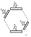
- Fig. 3 Dashed the cross section of the holding body, a first pair of similar bending beam (rectangles) in the 6 o'clock and 12 o'clock position, a second pair of similar bending beam in the 4 o'clock and 10 o'clock position and the externally acting disturbing forces analogous to Fig.
- the sensor pairs may differ from each other, and in particular have different materials, dimensions and in particular also resonance frequencies.
- Magnetic field measuring devices in this construction are similar to the known ME sensor arrays, which can be used, inter alia, to sensitively detect temporally periodic magnetic fields with a complex or variable frequency spectrum.
- the inventive feature here is that the holding body has a 2N-count rotational symmetry with respect to an axis of symmetry, and M pairs of similar bending beam sensors arranged with their long axes parallel to the symmetry axis and connected to the holding body, that the magnetic field measuring device with respect to the symmetry axis a twofold rotational symmetry where N and M are natural numbers.
- a rotational symmetry of the magnetic field measuring device is the speech, which not only describes the holding body and the geometric arrangement of the bending beam on the holding body, but also includes the orientation of the bending beam with respect to the axis of rotation.
- the undersides of the bending beam in the arrangement may optionally be facing the axis of rotation or facing away, but always so that similar Bending beam are symmetrically oriented and - if necessary, at least in pairs - bend in the presence of a detectable magnetic field synchronously on the axis of rotation to or away from it.
- the mechanical coupling of the bending beams introduced via the holding body makes it possible to maintain the symmetrical mechanical conditions, as long as the magnetic field measuring device performs a vibration only on the basis of a temporally periodic magnetic field.
- each bending bar detects a portion of the disturbance and outputs a disturbed voltage signal.
- the interference components cancel each other out in the sum of the signals with similar bending beams. If not all the bending beams used are similar, as in the last two embodiments, then it may be appropriate to weight the voltage signals of different bending beam pairs differently in the summation. Therefore, the generalization of the formation of a linear combination of all voltage signals of the bending beam as output of the magnetic field measuring device according to the invention is discussed here.
- the device is to be connected to at least one attachment point with a suitable tripod for fixing the position.
- the tripod can be a linkage or the housing of a measuring chamber, in any case, the tripod is a conductor for structure-borne noise.
- the attachment point of the magnetic field measuring device becomes the entry point for structure-borne noise into the sensor through the connection with the stand itself. It is particularly advantageous to choose this attachment point as close as possible to a force node and, moreover, the transmission of structure-borne noise from the stand by providing a sound-damping connection, e.g. by elastic gripper pillows in a clamping connection to suppress.
Abstract
Die Erfindung betrifft eine Magnetfeldmessvorrichtung umfassend einen Haltekörper und eine Mehrzahl magnetoelektrischer Biegebalkensensoren einzeln ausgebildet zur Ausgabe je eines elektrischen Spannungssignals unter Verbiegen bei Vorliegen eines Magnetfeldes, wobei die Biegebalkensensoren kraft- oder stoffschlüssig mit dem Haltekörper verbunden sind.The invention relates to a magnetic field measuring device comprising a holding body and a plurality of magnetoelectric bending beam sensors individually designed to output each of an electrical voltage signal under bending in the presence of a magnetic field, wherein the bending beam sensors are positively or materially connected to the holding body.
Description
Die Erfindung betrifft eine Magnetfeldmessvorrichtung umfassend eine Mehrzahl magnetoelektrischer Sensoren.The invention relates to a magnetic field measuring device comprising a plurality of magnetoelectric sensors.
Magnetoelektrische Sensoren, im Folgenden kurz ME-Sensoren, eignen sich zur Detektion u. a. kleiner zeitlich veränderlicher Magnetfelder, wie sie etwa durch biologische Aktionsströme in lebenden Organismen hervorgerufen werden, z.B. menschliche Hirnströme. ME-Sensoren bilden eine mögliche Schlüsseltechnologie zur Entwicklung biomagnetischer Schnittstellen, die zunächst in der medizinischen Diagnostik, z.B. MEG, MKG, und womöglich zukünftig auch in der Prothesensteuerung oder allgemein in der Mensch-Maschinen-Interaktion zur Anwendung kommen kann.Magnetoelectric sensors, in the following ME sensors for short, are suitable for detection u. a. small time-varying magnetic fields, such as those caused by biological action currents in living organisms, e.g. human brain waves. ME sensors are one possible key technology for the development of biomagnetic interfaces that are initially used in medical diagnostics, e.g. MEG, MKG, and possibly also in the future in the prosthetic control or in general in the human-machine interaction can be used.
Das Funktionsprinzip heutiger ME-Sensoren liegt in der mechanischen Kraftkopplung von magnetostriktiven und piezoelektrischen Materialien in einem Materialverbund.The functional principle of today's ME sensors lies in the mechanical power coupling of magnetostrictive and piezoelectric materials in a composite material.
Magnetostriktive Materialien, z.B. ferromagnetische Übergangsmetalle Fe, Ni, Co und deren Legierungen, Verbindungen der Seltenen Erden Tb, Dy, Sm mit den ferromagnetischen Übergangsmetallen, z.B. TbFe2, SmFe2, oder auch ferromagnetische Gläser vorwiegend enthaltend die Elemente Eisen, Kobalt, Bor oder Silizium in variierenden Anteilen, erfahren eine reversible Längenänderung entlang der Richtung eines auf sie einwirkenden Magnetfeldes. Verbindet man ein magnetostriktives Material stoffschlüssig mit einem Piezoelektrikum, z.B. Bleizirkonattitanat PZT, Polyvinylidenfluorid PVDF, Aluminiumnitrid AIN, so bewirkt die magnetostriktive Längenänderung zugleich eine Kraft auf das Piezoelektrikum, was dort zu einer strukturellen Ladungsverschiebung führt und eine messbare Piezospannung nach sich zieht. Diese Spannung kann als Maß für die magnetische Feldstärke elektronisch erfasst und ausgewertet werden.Magnetostrictive materials, such as ferromagnetic transition metals Fe, Ni, Co and their alloys, rare earth compounds Tb, Dy, Sm with the ferromagnetic transition metals, eg TbFe2, SmFe2, or ferromagnetic glasses predominantly containing the elements iron, cobalt, boron or silicon in varying proportions undergo a reversible change in length along the direction of a magnetic field acting on them. If a magnetostrictive material is connected in a materially bonded manner to a piezoelectric, eg lead zirconate titanate PZT, polyvinylidene fluoride PVDF, aluminum nitride AIN, the magnetostrictive change in length simultaneously effects a force on the piezoelectric element, which leads to a structural charge shift there results in a measurable piezo voltage. This voltage can be electronically recorded and evaluated as a measure of the magnetic field strength.
Zu den einfachsten Ausführungsformen eines ME-Sensors zählt ein sogenannter Biegebalkensensor. Dieser weist - oft auf einem Glasträger oder auf einem Halbleitersubstrat - eine Abfolge verschiedener Materialschichten auf, wobei wenigstens eine Schicht aus einem magnetostriktiven Material und wenigstens eine weitere Schicht aus einem Piezoelektrikum besteht. In der gängigen Bauweise sind zusätzlich Elektroden oberhalb und unterhalb der piezoelektrischen Schicht angeordnet, um die Piezospannung bei Deformation der üblich senkrecht zum Schichtverlauf gepolten Piezoschicht abzugreifen. Magnetostriktive Materialien sind gewöhnlich metallisch leitend und werden unmittelbar mit dem Piezoelektrikum kontaktiert, um direkt als eine der Elektroden zu dienen. Aber auch andere Aufbauvarianten für ME-Biegebalkensensoren sind bekannt.Among the simplest embodiments of a ME sensor is a so-called bending beam sensor. This has - often on a glass substrate or on a semiconductor substrate - a sequence of different material layers, wherein at least one layer of a magnetostrictive material and at least one further layer consists of a piezoelectric element. In the conventional design, electrodes are additionally arranged above and below the piezoelectric layer in order to tap the piezoelectric voltage during deformation of the piezo layer which is normally polarized perpendicularly to the layer profile. Magnetostrictive materials are usually metallically conductive and are contacted directly with the piezoelectric to serve directly as one of the electrodes. But other body variants for ME bending beam sensors are known.
Ein ME-Biegebalkensensor hat üblich die Form eines rechteckigen Streifens. Die Richtung, entlang der das magnetostriktive Material seine größte Längenänderung gegenüber kleinen Magnetfeldern zeigt, ist u. a. durch eine Temperaturbehandlung im vorbekannten Magnetfeld - "magnetic field annealing" - bei der Herstellung des Sensors einstellbar. In aller Regel wird diese Richtung mit der langen Achse der Streifen in Übereinstimmung gebracht. Unter der Einwirkung eines Magnetfeldes entlang der langen Achse verbiegt sich dann der Streifen infolge der unterschiedlichen Materialausdehnung schon bei kleinen Magnetfeldbeträgen und erzeugt so eine messbare Signalspannung.A ME bending beam sensor is usually in the form of a rectangular strip. The direction along which the magnetostrictive material exhibits its greatest change in length relative to small magnetic fields is u. a. by a temperature treatment in the known magnetic field - "magnetic field annealing" - adjustable in the manufacture of the sensor. As a rule, this direction is matched with the long axis of the strips. Under the influence of a magnetic field along the long axis, the strip then bends due to the different material expansion even at small magnetic field amounts and thus generates a measurable signal voltage.
Magnetostriktive und piezoelektrische Materialien können mit an sich bekannten Beschichtungstechniken aufeinander und/oder auf vorbestimmten Substraten abgeschieden werden. Die Herstellung von ME-Sensoren ist insoweit mit Prozessen der Silizium-Technologie kompatibel; insbesondere sind integrierte ME-Sensoren etwa in MEMS-Bauweise - Micro Electrical Mechanical Systems - herstellbar. Aber auch die getrennte Erzeugung von magnetostriktiven und piezoelektrischen Folien und das anschließende Verkleben beider zu einer ME-Folie sind geeignet, Magnetfeldsensoren nach dem beschriebenen Prinzip zu erzeugen.Magnetostrictive and piezoelectric materials can be deposited on one another and / or on predetermined substrates by means of coating techniques known per se. The manufacture of ME sensors is so far compatible with processes of silicon technology; In particular, integrated ME sensors, for example, in MEMS design - Micro Electrical Mechanical Systems - can be produced. But also the separate generation of magnetostrictive and Piezoelectric films and the subsequent bonding of both to a ME film are suitable to produce magnetic field sensors according to the described principle.
ME-Sensoren sind mechanische Oszillatoren. Unter Einwirkung eines periodischen Magnetfeldes definierter Frequenz zeigen sie ein erzwungenes mechanisches Schwingungsverhalten. Erfolgt die Anregung dabei mit der mechanischen Resonanzfrequenz des ME-Sensors, dann rufen selbst sehr kleine Magnetfeldstärken sehr große Messspannungen hervor.ME sensors are mechanical oscillators. Under the influence of a periodic magnetic field of defined frequency they show a forced mechanical vibration behavior. If the excitation occurs with the mechanical resonance frequency of the ME sensor, even very small magnetic field strengths cause very large measuring voltages.
Biologisch erzeugte Magnetfelder weisen typisch nur Frequenzen der Größenordnungen 1 Hz bis ungefähr 100 Hz auf. Demgegenüber liegen die Resonanzfrequenzen gängiger ME-Sensoren gewöhnlich bei etlichen 100 Hz bis zu einigen 100 kHz. Das Verhältnis der im ME-Sensor hervorgerufenen elektrischen Feldstärkeamplitude zur anregenden magnetischen Feldstärkeamplitude wird als ME-Koeffizient, αME, bezeichnet. Zwischen Messungen von Magnetfeldern im Resonanzfall und weit außerhalb der Resonanz variiert der ME-Koeffizient typisch um zwei bis drei Größenordnungen.Biologically generated magnetic fields typically have only frequencies of the order of magnitude of 1 Hz to approximately 100 Hz. In contrast, the resonance frequencies of common ME sensors are usually at several 100 Hz up to several 100 kHz. The ratio of the electric field strength amplitude produced in the ME sensor to the exciting magnetic field strength amplitude is referred to as the ME coefficient, α ME . Between measurements of magnetic fields at resonance and far out of resonance, the ME coefficient typically varies by two to three orders of magnitude.
Gewöhnlich werden ME-Sensoren auch außerhalb ihrer mechanischen Resonanz betrieben. Da man an einer möglichst großen Messdynamik, einem möglichst großen Signal-Rausch-Verhältnis und an der Linearität der Spannungsantwort auf das zu messende Magnetfeld interessiert ist, wählt man für den ME-Sensor üblich einen Arbeitspunkt im linearen Bereich der Magnetostriktionskennlinie.Usually, ME sensors are also operated outside of their mechanical resonance. Since one is interested in the largest possible dynamic range, the largest possible signal-to-noise ratio and the linearity of the voltage response to the magnetic field to be measured, one usually chooses an operating point in the linear region of the magnetostriction characteristic for the ME sensor.
Die Magnetostriktionskennlinie beschreibt die Längenausdehnung eines magnetostriktiven Materials entlang einer vorbestimmten Richtung, wenn es einer Magnetfeldstärke vom Betrag H ausgesetzt ist. Ein Vorzeichenwechsel von H entspricht dabei einer magnetischen Feldumkehr, und da beide Feldrichtungen denselben Effekt auf das Material haben, verläuft die Magnetostriktionskennlinie grundsätzlich symmetrisch zu H = 0. Die Magnetostriktionskennlinie zeigt um H = 0 einen parabolischen Verlauf, ist aber bei hohen Feldstärken dadurch beschränkt, dass alle magnetischen Domänen irgendwann gleich ausgerichtet sind. Sie besitzt folglich zwei Wendepunkte bei ± HB, wo sie näherungsweise linear verläuft und die größten Steigungen aufweist.The magnetostriction characteristic describes the linear expansion of a magnetostrictive material along a predetermined direction when subjected to a magnetic field intensity of magnitude H. A sign change of H corresponds to a magnetic field reversal, and since both field directions have the same effect on the material, the magnetostriction characteristic is basically symmetrical to H = 0. The magnetostriction characteristic shows H = 0 has a parabolic course, but is limited at high field strengths by the fact that all magnetic domains are aligned at some point. It thus has two inflection points at ± H B where it is approximately linear and has the largest slopes.
Um den ME-Sensor in diesem vorteilhaften Arbeitspunkt zu betreiben, wird in vielen Fällen ein konstantes Bias-Magnetfeld der Feldstärke HB durch das geeignete Anordnen von Stromleitern oder Permanentmagneten angelegt.In order to operate the ME sensor in this advantageous operating point, in many cases a constant bias magnetic field of the field strength H B is applied by the appropriate arrangement of current conductors or permanent magnets.
ME-Sensoren unterliegen internen und externen Störeinflüssen, u. a. thermischen Fluktuationen der elektronischen Materialeigenschaften und ungewollt übertragenen mechanischen Vibrationen durch Luft- oder Körperschall. Präzisionsmessungen erfordern daher häufig den Einbau des ME-Sensors in eine Messkammer, in der die Temperatur stabilisiert oder die sogar evakuiert werden kann. Gleichwohl können Vibrationen der Messkammer im Labor meist nicht ausgeschlossen werden, so dass auch über eine mechanisch gedämpfte Halterung des ME-Sensors immer noch Störungen in das Messsignal eingetragen werden können. Überhaupt ist die Verwendung einer solchen Messkammer für viele praktische Messaufgaben keine Option.ME sensors are subject to internal and external interference, u. a. thermal fluctuations of the electronic material properties and unintentionally transmitted mechanical vibrations due to airborne or structure-borne noise. Precision measurements therefore often require the installation of the ME sensor in a measuring chamber in which the temperature can be stabilized or even evacuated. Nevertheless, vibrations of the measuring chamber in the laboratory can usually not be ruled out, so that disturbances in the measuring signal can still be registered via a mechanically damped mounting of the ME sensor. In general, the use of such a measuring chamber is not an option for many practical measuring tasks.
In der Arbeit
Neben den ME-Sensoren sind auch Stimmgabel-Sensoren zur Magnetfeldmessung bekannt. Das Funktionsprinzip besteht darin, einen mechanischen Oszillator - gewöhnlich in der Form einer Stimmgabel mit Zinken - zu Schwingungen in der Nähe seiner Resonanzfrequenz anzuregen, die Parameter der Oszillation - Frequenz, Phase, Amplitude - zu überwachen, und aus Änderungen dieser Parameter auf ein anwesendes Magnetfeld zu schließen. Etwa das Anordnen von Permanentmagneten an den Zinken der Stimmgabel, wie vorgeschlagen in der Druckschrift
Der eingangs beschriebene ME-Biegebalkensensor besticht durch seine einfache und kostengünstige Herstellbarkeit und erscheint gerade für biomagnetische Feldmessungen besonders geeignet.The ME bending beam sensor described at the beginning impresses with its simple and cost-effective manufacturability and is especially suitable for biomagnetic field measurements.
Es ist daher die Aufgabe der Erfindung, eine Magnetfeldmessvorrichtung auf der Basis von ME-Biegebalkensensoren vorzuschlagen, die eine per Konstruktion bedingte Fähigkeit zur Vibrationskompensation aufweist und somit weitgehend unempfindlich gegenüber dem Eintrag mechanischer Schwingungen durch Luft- oder Körperschall ist.It is therefore an object of the invention to provide a magnetic field measuring device based on ME bending beam sensors, which has a conditional by design capability for vibration compensation and thus is largely insensitive to the entry of mechanical vibrations by airborne or structure-borne noise.
Die Aufgabe wird gelöst durch eine Magnetfeldmessvorrichtung umfassend einen Haltekörper und eine Mehrzahl magnetoelektrischer Biegebalkensensoren einzeln ausgebildet zur Ausgabe je eines elektrischen Spannungssignals unter Verbiegen bei Vorliegen eines Magnetfeldes, wobei die Biegebalkensensoren kraft- oder stoffschlüssig mit dem Haltekörper verbunden und sind, dadurch gekennzeichnet, dass
- a. die Biegebalkensensoren mit parallel verlaufenden langen Achsen zur Detektion desselben Magnetfeldes angeordnet sind, so dass
- b. die Magnetfeldmessvorrichtung durch ein zeitlich periodisches Magnetfeld zu einer mechanischen Schwingung erregbar ist, die
- c. sich derart ausbildet, dass die Magnetfeldmessvorrichtung wenigstens einen Kraftknotenpunkt aufweist, an dem zu keiner Zeit eine durch die Schwingung bedingte resultierende Kraft angreift, und
- d. die Magnetfeldmessvorrichtung eine Linearkombination der Spannungssignale der Biegebalkensensoren ausgibt.
- a. the bending beam sensors are arranged with parallel long axes for detecting the same magnetic field, so that
- b. the magnetic field measuring device is excitable by a temporally periodic magnetic field to a mechanical vibration, the
- c. is formed in such a way that the magnetic field measuring device has at least one power node on which at no time attacks a resulting force due to the vibration, and
- d. the magnetic field measuring device outputs a linear combination of the voltage signals of the bending beam sensors.
Die in der Arbeit von Xing et al. (2009) geäußerte Feststellung, dass symmetrisch aufgebaute ME-Magnetfeldsensoren die Vibrationskompensation erlauben, wird von der Erfindung aufgegriffen und in eine neue Richtung fortgebildet.The work described by Xing et al. (2009) that symmetrically constructed ME magnetic field sensors allow the vibration compensation is taken up by the invention and developed in a new direction.
Der Erfindungsansatz besteht darin, eine Mehrzahl von Biegebalkensensoren an einem gemeinsamen Haltekörper derart anzuordnen, dass alle Biegebalken zum einen dasselbe Magnetfeld messen und zum anderen Vibrationseinträge in die Gesamtanordnung in allen Biegebalken Störsignale erzeugen, die sich durch eine Linearkombination aller Ausgangsspannungen der Biegebalken auslöschen.The inventive approach consists of arranging a plurality of bending beam sensors on a common holding body in such a way that all the bending beams measure the same magnetic field and generate interference signals in the overall arrangement in all the bending beams which cancel each other out by a linear combination of all output voltages of the bending beams.
Der Haltekörper ist dabei ein starrer Körper, der eine mechanische Kopplung der Oszillationen aller Biegebalken ermöglicht. Der Haltekörper kann aus einem Halbleiter, einem Metall, einem Kunststoff, z.B. Polymethylmetacrylat PMMA, oder auch aus einem Glas bestehen. Er besitzt vorzugsweise eine N-zählige Symmetrieachse, wobei N eine natürliche Zahl größer als Eins ist. Der Haltekörper kann auch die Form eines Zylinders haben (N → ∞).The holding body is a rigid body, which allows a mechanical coupling of the oscillations of all bending beams. The holding body may be made of a semiconductor, a metal, a plastic, e.g. Polymethyl methacrylate PMMA, or even consist of a glass. It preferably has an N-fold symmetry axis, where N is a natural number greater than one. The holding body can also have the shape of a cylinder (N → ∞).
Die Biegebalken und der Haltekörper zusammen sollen unter Einwirkung eines zeitlich periodischen Magnetfeldes mechanisch schwingfähig sein. Zu diesem Zweck sind die Biegebalken stoff- oder kraftschlüssig mit dem Haltekörper verbunden, beispielsweise verklebt, verlötet, versintert oder mit Klemmen befestigt. Vorzugsweise sind die streifenförmigen Biegebalken jeweils an einem Streifenende mit dem Haltekörper verbunden.The bending beam and the holding body together should be mechanically vibratable under the action of a time-periodic magnetic field. For this purpose, the bending beams are material or non-positive with the holding body connected, for example glued, soldered, sintered or secured with clamps. Preferably, the strip-shaped bending beams are each connected at one end of the strip to the holding body.
Die Gesamtheit aus der Anordnung der Biegebalken, dem Haltekörper und der Verschaltung der Biegebalken-Spannungsausgänge zur Bildung der geeigneten Linearkombination der Spannungssignale stellt - ggf. in baulicher Einheit - die erfindungsgemäße Magnetfeldmessvorrichtung dar. Diese Vorrichtung kann allein durch ein zeitlich periodisches Magnetfeld in eine mechanische Schwingung versetzt werden. Erfindungsgemäß existiert während dieser Schwingung wenigstens ein Punkt der Vorrichtung, der zu keinem Zeitpunkt in Bewegung versetzt wird, weil zu keiner Zeit eine durch die Schwingung bedingte, resultierende Kraft auf ihn wirkt. Ein solcher Punkt wird hier als Kraftknotenpunkt bezeichnet.The entirety of the arrangement of the bending beam, the holding body and the interconnection of the bending beam voltage outputs to form the appropriate linear combination of the voltage signals represents - possibly in a structural unit - the magnetic field measuring device according to the invention. This device can alone by a time-periodic magnetic field in a mechanical vibration be offset. According to the invention, during this oscillation there is at least one point of the device which is never set in motion because at no time does a resultant force resulting from the oscillation act on it. Such a point is referred to here as a force node.
Der Kraftknotenpunkt wird allerdings durch Vibrationen, die von außen durch Luft- oder Körperschall in die Magnetfeldmessvorrichtung eingetragen werden, in Bewegung versetzt. Die Anordnung der Biegebalkensensoren detektiert dann in jedem einzelnen Biegebalken eine vibrationsbedingte Störung neben dem zu messenden Magnetfeld. Die erzeugten Spannungssignale sind für die einzelnen Biegebalken nicht nach Ursachen separierbar. Die Erfindung lehrt nun, dass eine Linearkombination der Spannungssignale gebildet werden kann, in der sich die Anteile der Vibrationsstörung kompensieren, wenn die Biegebalken so angeordnet sind, dass die Vorrichtung wenigstens einen Punkt aufweist, der bei Vorliegen eines zeitlich periodischen Magnetfeldes und in Abwesenheit einer Vibration während der durch das Magnetfeld hervorgerufenen Schwingung zu jeder Zeit in Ruhe verbleibt.The power node is, however, caused by vibrations that are entered from the outside by air or structure-borne noise in the magnetic field measuring device in motion. The arrangement of the bending beam sensors then detects in each individual bending beam a vibration-induced disturbance in addition to the magnetic field to be measured. The generated voltage signals are not separable for the individual bending beam for reasons. The invention now teaches that a linear combination of the voltage signals can be formed in which the components of the vibration noise compensate when the bending beams are arranged so that the device has at least one point in the presence of a temporally periodic magnetic field and in the absence of vibration while the vibration caused by the magnetic field remains at rest at all times.
Die Erfindung wird nachfolgend näher erläutert auch anhand von Beispielen und Zeichnungen. Dabei zeigt:
- Fig. 1
- eine Skizze eines Querschnitts durch eine Anordnung von drei gleichartigen ME-Biegebalkensensoren (Rechtecke) mit Kräften, die infolge einer Vibrationsstörung auf die Anordnung einwirken;
- Fig. 2
- eine Skizze eines Querschnitts durch eine Anordnung von vier ME-Biegebalkensensoren (Rechtecke) umfassend zwei Paare paarweise gleichartiger Sensoren, befestigt an einem würfel- oder quaderförmigen Haltekörper und
- Fig. 3
- eine Skizze eines Querschnitts durch eine Anordnung von vier ME-Biegebalkensensoren (Rechtecke) umfassend zwei Paare paarweise gleichartiger Sensoren, befestigt an einem Sechskant-Haltekörper.
- Fig. 1
- a sketch of a cross section through an arrangement of three similar ME bending beam sensors (rectangles) with forces acting on the assembly due to a vibration disturbance;
- Fig. 2
- a sketch of a cross section through an arrangement of four ME bending beam sensors (rectangles) comprising two pairs of pairs of similar sensors, attached to a cube or cuboid holding body and
- Fig. 3
- a sketch of a cross section through an arrangement of four ME bending beam sensors (rectangles) comprising two pairs of pairs of similar sensors, attached to a hexagonal holding body.
Für die weitere Beschreibung sind zunächst einige Begriffsklärungen zweckmäßig:
- Ein ME-Biegebalkensensor in Streifenform weist eine erste und eine zweite Flachseite auf. Gewöhnlich werden die Sensoren so hergestellt, dass beide Flachseiten in Abwesenheit eines zu messenden Magnetfeldes gleich lang sind, der Streifen also gerade ist.
- A ME flexion bar sensor in strip form has first and second flat sides. Usually, the sensors are made so that both flat sides in the absence of a magnetic field to be measured are the same length, so the strip is straight.
Dabei wird in dieser Beschreibung stets angenommen, dass sich der ME-Biegebalkensensor von Vornherein in einem vorteilhaften Arbeitspunkt zur Magnetfeldmessung befindet. Dies kann, wie weiter oben erläutert, durch das Anordnen von Permanentmagneten erfolgen, welche ein konstantes Bias-Feld entlang der langen Achse des Biegebalkens erzeugen. Es ist aber auch bekannt, Biegebalken als Schichtsysteme mit wenigstens einer antiferromagnetischen Schicht auszugestalten, die einen solchen Arbeitspunkt mittels Pinning der Elementardipole durch Exchange Bias erzielen. Ein solcher Aufbau weist nur ein sehr schwaches, konstruktionsbedingtes, zeitlich konstantes Magnetfeld auf im Vergleich zu dem herkömmlichen Bias-Magnetfeld. Unabhängig davon, auf welche Weise der Arbeitspunkt genau eingestellt wird, wird von nun an vorausgesetzt, dass er im linearen Bereich der Magnetostriktionskennlinie der magnetostriktiven Schicht des Biegebalkens liegt. In der weiteren Beschreibung werden konstruktionsbedingte, zeitlich konstante Magnetfelder, insbesondere Bias-Magnetfelder, die den Arbeitspunkt des ME-Biegebalkens festlegen, nicht mehr explizit angesprochen.It is always assumed in this description that the ME bending beam sensor is located from the outset in an advantageous operating point for magnetic field measurement. This can, as explained above, be achieved by arranging permanent magnets which produce a constant bias field along the long axis of the bending beam. However, it is also known to design bending beams as layer systems with at least one antiferromagnetic layer which achieve such an operating point by means of pinning of the elementary dipoles by exchange bias. Such a structure has only a very weak, design-related, temporally constant magnetic field compared to the conventional bias magnetic field. Regardless of how exactly the operating point is set, it will from now on provided that it is in the linear region of the magnetostriction characteristic of the magnetostrictive layer of the bending beam. In the further description, design-related, temporally constant magnetic fields, in particular bias magnetic fields, which define the operating point of the ME bending beam, are no longer explicitly addressed.
Liegt ein zu messendes Magnetfeld mit vorbestimmter Richtung entlang der langen Achse des Biegebalkens vor, ändert sich die Länge wenigstens einer der beiden Flachseiten, und der Biegebalken verbiegt sich. Es soll im Folgenden als Oberseite des Streifens diejenige Flachseite bezeichnet werden, die in dem durch ein Magnetfeld mit vorbestimmter Richtung verbogenen Zustand die längere ist. Entsprechend wird die gegenüberliegende kürzere Flachseite von nun an die Unterseite genannt. Im Folgenden beziehen sich die Bezeichnungen Ober- und Unterseite aller ME-Biegebalken einer Anordnung immer auf dieselbe vorbestimmte Magnetfeldrichtung. Dies ist hier unproblematisch, da in der erfindungsgemäßen Magnetfeldmessvorrichtung alle Biegebalken stets so angeordnet sind, dass ihre langen Achsen parallel verlaufen.If there is a magnetic field to be measured with a predetermined direction along the long axis of the bending beam, the length of at least one of the two flat sides changes, and the bending beam bends. It will be referred to below as the top of the strip that flat side which is the longer in the bent by a magnetic field with a predetermined direction state. Accordingly, the opposite shorter flat side is called from now on the bottom. In the following, the terms upper and lower side of all ME bending beams of an arrangement always refer to the same predetermined magnetic field direction. This is not a problem here, since in the magnetic field measuring device according to the invention all the bending beams are always arranged so that their long axes are parallel.
Es ist für den Zweck der Erfindung vorteilhaft, im Idealfall baugleiche ME-Biegebalkensensoren in die erfindungsgemäße Anordnung zu bringen. Doch ist Baugleichheit eine starke Anforderung, die aus praktischen Gründen nicht immer erfüllt werden kann. Für die Erfindung reicht es aus, wenn Biegebalkensensoren verwendet werden, die etwa die gleiche Masse und Länge besitzen und unter Einwirkung eines Magnetfeldes die gleiche Verbiegung zeigen und das gleiche Spannungssignal ausgeben.It is advantageous for the purpose of the invention, ideally bring identical ME bending beam sensors in the inventive arrangement. However, structural equality is a strong requirement that can not always be met for practical reasons. For the invention, it is sufficient if bending beam sensors are used which have approximately the same mass and length and under the action of a magnetic field show the same deflection and output the same voltage signal.
Beispielsweise können Biegebalkensensoren erzeugt werden, die sich hinsichtlich der Substrate, z.B. Siliziumstreifen, der Funktionsmaterialien, z.B. Metglas und PZT, und aller Dimensionierungen - Längen, Schichtdicken, Schichtanordnung - nicht unterscheiden, aber verschiedene Elektrodenmaterialien, z.B. Gold oder Platin, für den Spannungsabgriff aufweisen. Die Elektrodenschichten von einigen Nanometern Dicke spielen für das mechanische Verhalten des Biegebalkens und das Spannungssignal des ME-Sensors keine Rolle. Diese Sensoren sind nicht baugleich, aber jedenfalls allein durch ihre mechanische oder elektrische Antwort auf ein Magnetfeld nicht voneinander zu unterscheiden. Sensoren mit dieser Eigenschaft werden im Kontext der weiteren Beschreibung als gleichartig bezeichnet.For example, cantilever sensors can be produced which do not differ with respect to the substrates, eg silicon strips, the functional materials, eg Metglas and PZT, and all dimensions - lengths, layer thicknesses, layer arrangement - but have different electrode materials, eg gold or platinum, for the voltage tap. The electrode layers of a few nanometers thickness play for the mechanical Behavior of the bending beam and the voltage signal of the ME sensor does not matter. These sensors are not identical, but in any case can not be distinguished from one another solely by their mechanical or electrical response to a magnetic field. Sensors with this property are referred to as similar in the context of the further description.
Zum besseren Verständnis der Erfindung wird zunächst ein sehr einfaches Ausführungsbeispiel beschrieben.For a better understanding of the invention, a very simple embodiment will be described first.
An zwei gegenüberliegenden Flachseiten eines quaderförmigen Haltekörpers sind zwei gleichartige Biegebalkensensoren angeordnet. Beide Biegebalkensensoren sind mit je einem ihrer Balkenenden mit einer Klemme durch Andruck ihrer Unterseiten am Haltekörper befestigt und weisen mit ihren langen Achsen in dieselbe Richtung. Die Biegebalken stehen sich mit zueinander weisenden Unterseiten genau gegenüber in einem Abstand, der durch die Dimensionen des Haltekörpers bestimmt ist. Dieser Abstand soll klein sein, aber nicht so klein, dass sich die Biegebalken bei der Verbiegung berühren könnten. Rein optisch sieht diese Ausführungsform einer Stimmgabel ähnlich, deren Zinken durch die Biegebalken gebildet werden. Der Aufbau ist mechanisch schwingfähig. Er besitzt eine 2-zählige Rotationssymmetrieachse, nämlich durch den Mittelpunkt des Haltekörpers parallel zu den langen Achsen der Biegebalken verlaufend.Two similar bending beam sensors are arranged on two opposite flat sides of a cuboid holding body. Both bending beam sensors are each secured with one of their beam ends with a clamp by pressing their undersides on the holding body and point with their long axes in the same direction. The bending beams are exactly opposite to each other at a distance, which is determined by the dimensions of the holding body. This distance should be small, but not so small that the bending beam could touch during bending. In purely optical terms, this embodiment resembles a tuning fork whose tines are formed by the bending beams. The structure is mechanically oscillatable. It has a 2-fold rotational symmetry axis, namely passing through the center of the holding body parallel to the long axes of the bending beam.
Ein zeitlich periodisches Magnetfeld, das von beiden Biegebalken gleichzeitig detektiert wird, bewirkt nun die Verbiegung der Biegebalken aufeinander zu und - bei Feldrichtungsumkehr - voneinander weg. Der Aufbau vollführt eine erzwungene mechanische Schwingung mit der Periode des Magnetfeldes, also nicht unbedingt mit der Resonanzfrequenz des Aufbaus, die deutlich höher liegen kann. Es liegt hier keine Variante eines an sich bekannten Stimmgabel-Sensors vor.A temporally periodic magnetic field, which is detected by both bending beams simultaneously, now causes the deflection of the bending beam toward each other and - in reversing the field direction - away from each other. The structure performs a forced mechanical vibration with the period of the magnetic field, so not necessarily with the resonant frequency of the structure, which can be significantly higher. There is no variant of a known tuning fork sensor here.
Gleichwohl wird eine Schwingungsbewegung vollführt, die mit der bekannten Stimmgabel-Oszillation vergleichbar ist. Insbesondere existiert wenigstens ein Punkt der Vorrichtung, der sich zu jedem Zeitpunkt im Kräftegleichgewicht befindet, also keine resultierende Kraft aus der Schwingung erfährt und in Ruhe bleibt: ein Kraftknotenpunkt, der hier auf der Rotationssymmetrieachse im Haltekörper liegt.However, a vibratory motion is performed which is comparable to the known tuning fork oscillation. In particular, there exists at least one point of the device which is in equilibrium of forces at all times, that is to say that no resultant force is experienced from the oscillation and remains at rest: a force node located here on the rotational symmetry axis in the holding body.
Beide Biegebalken erzeugen während der Schwingung ein Spannungssignal, das bei gleichartigen Sensoren - innerhalb der durch Messungenauigkeiten begründeten Fehlergrenzen - zu jeder Zeit hinsichtlich Betrag und Vorzeichen gleich groß ist. Addiert man beide Signale, erhält man die doppelte ME-Sensorspannung für ein vorliegendes Magnetfeld in Abwesenheit einer störenden Vibration.Both bending beams generate a voltage signal during oscillation, which is identical in magnitude and sign in the case of similar sensors-within the error limits established by measurement inaccuracies. Adding both signals gives twice the ME sensor voltage for a given magnetic field in the absence of disturbing vibration.
Tritt nun eine Vibration durch Luft- oder Körperschalleintrag während der Magnetfeldmessung zusätzlich auf, so verursacht diese Störung in jedem Punkt der Vorrichtung eine weitere - in der Regel selbst zeitabhängige - Krafteinwirkung. Die relativ beweglichen Biegebalken erfahren hierdurch zusätzliche Verbiegungen, wenn eine Kraftkomponente senkrecht zu den Flachseiten der Biegebalken angreift. Allerdings weist diese Kraftkomponente an beiden Biegebalken zu jeder Zeit in die gleiche Richtung, d. h. bei dem einen Biegebalken wird die Verbiegung verstärkt und bei dem anderen gleichzeitig abgeschwächt. Der Einfluss der Vibration auf die Spannungssignale der Biegebalken ist insofern jederzeit gegenphasig, und in der Tat zeigt sich bei der Addition der beiden Signale, dass die Vibration im Summensignal kompensiert ist.Now occurs when a vibration by air or Körperschalleintrag during the magnetic field measurement in addition, so this disorder causes in each point of the device another - usually self-time-dependent - force. The relatively movable bending beam thereby undergo additional bending when a force component acts perpendicular to the flat sides of the bending beam. However, this force component on both bending beams at all times in the same direction, d. H. in one bending beam, the bending is amplified and at the same time attenuated in the other. The influence of the vibration on the voltage signals of the bending beam is in this case always in opposite phase, and in fact shows in the addition of the two signals that the vibration in the sum signal is compensated.
Die eingangs genannte Linearkombination der Spannungssignale der Biegebalken ist somit beispielsweise und bevorzugt die Addition.The above-mentioned linear combination of the voltage signals of the bending beam is thus, for example, and preferably the addition.
Dasselbe gilt für das zweite Ausführungsbeispiel, das auch in
Weiterhin ist in
Der Fachmann sieht nach dem Gesagten ohne Weiteres ein, dass sich weitere Ausgestaltungen einer erfindungsgemäßen Magnetfeldmessvorrichtung sehr leicht entwerfen lassen, wobei der Haltekörper eine N-zählige Rotationssymmetrie bezüglich einer Symmetrieachse aufweist, und M gleichartige Biegebalkensensoren derart mit ihren langen Achsen parallel zur Symmetrieachse angeordnet und mit dem Haltekörper verbunden sind, dass die Magnetfeldmessvorrichtung bezüglich der Symmetrieachse eine M-zählige Rotationssymmetrie aufweist, wobei N eine natürliche Zahl größer als Eins und M ein Teiler von N und größer als Eins ist.The person skilled in the art readily recognizes that further embodiments of a magnetic field measuring device according to the invention can be designed very easily, the holding body having an N-fold rotational symmetry with respect to an axis of symmetry, and M similar bending beam sensors arranged with their long axes parallel to the axis of symmetry and with are connected to the holding body, that the magnetic field measuring device with respect to the axis of symmetry has an M-fold rotational symmetry, where N is a natural number greater than one and M is a divisor of N and greater than one.
Im ersten Ausführungsbeispiel gilt N = M = 2. Für das zweite Ausführungsbeispiel kann man N = M = 3 verwenden, aber ebenso auch N = 6 und M = 3.In the first embodiment, N = M = 2. For the second embodiment, one can use N = M = 3, but also N = 6 and M = 3.
Als drittes Ausführungsbeispiel soll erneut ein Quader als Haltekörper vorgestellt werden, der eine zweizählige Rotationssymmetrieachse und zwei Paare gleicher ebener, durch Rotation ineinander überführbarer Seitenwände aufweist. Es reicht nun aus, an einem Paar gleicher Seitenwände ein Paar gleichartiger ME-Biegebalkensensoren - wie zuvor mit ihrer Unterseite zur Rotationssymmetrieachse weisend - anzuordnen, womit man beim ersten Ausführungsbeispiel angelangt. Das zweite Paar gleicher Seitenwände kann zusätzlich genauso mit einem zweiten Paar gleichartiger Biegebalken versehen werden, wobei es aber keineswegs erforderlich ist, dass auch die Sensoren des ersten und des zweiten Paares gleichartig sind. Beispielsweise kann man ein Paar langer und ein Paar kurzer Biegebalken verwenden. Die Vibrationskompensation ergibt sich wie zuvor aus der Symmetrie des Aufbaus, und auch hier ist wieder die Summe aller Spannungssignale der Biegebalkensensoren vibrationskompensiert. Eine Querschnittsskizze der Anordnung ist in
Das vierte und letzte Ausführungsbeispiel betrifft einen Sechskant-Haltekörper, also mit sechszähliger Rotationssymmetrie und sechs gleichen Seitenwänden. An diesen können nach Wahl des Anwenders ein, zwei oder drei Paare von Biegebalken angeordnet werden. Auch hier sind die Biegebalkensensoren paarweise gleichartig, wobei jedes Paar zwei gegenüberliegende Seitenwände des Haltekörpers belegt. Beispielsweise zeigt
Zur Verdeutlichung sei noch einmal ausdrücklich gesagt, dass für die vorgenannten Ausführungsbeispiele von einer Rotationssymmetrie der Magnetfeldmessvorrichtung die Rede ist, die nicht nur den Haltekörper und die geometrische Anordnung der Biegebalken am Haltekörper beschreibt, sondern die auch die Orientierung dieser Biegebalken bezüglich der Rotationsachse umfasst. Die Unterseiten der Biegebalken in der Anordnung können wahlweise der Rotationsachse zu- oder abgewandt sein, jedoch stets so, dass gleichartige Biegebalken symmetrisch orientiert sind und sich - ggf. wenigstens paarweise - bei Vorliegen eines detektierbaren Magnetfeldes synchron auf die Rotationsachse zu oder von ihr weg verbiegen. Dann ermöglicht die über den Haltekörper eingeführte mechanische Kopplung der Biegebalken die Erhaltung der symmetrischen mechanischen Verhältnisse, solange die Magnetfeldmessvorrichtung eine Schwingung nur aufgrund eines zeitlich periodischen Magnetfeldes vollführt.For clarity, it is expressly stated again that for the aforementioned embodiments of a rotational symmetry of the magnetic field measuring device is the speech, which not only describes the holding body and the geometric arrangement of the bending beam on the holding body, but also includes the orientation of the bending beam with respect to the axis of rotation. The undersides of the bending beam in the arrangement may optionally be facing the axis of rotation or facing away, but always so that similar Bending beam are symmetrically oriented and - if necessary, at least in pairs - bend in the presence of a detectable magnetic field synchronously on the axis of rotation to or away from it. Then, the mechanical coupling of the bending beams introduced via the holding body makes it possible to maintain the symmetrical mechanical conditions, as long as the magnetic field measuring device performs a vibration only on the basis of a temporally periodic magnetic field.
Tritt zusätzlich eine Störung der Magnetfeldmessvorrichtung durch den Eintrag einer Vibration via Luft- oder Körperschall auf, wird die per Konstruktion erzeugte Symmetrie der Bewegung gestört, und jeder Biegebalken erfasst einen Anteil der Störung und gibt eine gestörtes Spannungssignal aus. Wie zuvor erläutert, löschen sich die Störanteile jedoch in der Summe der Signale bei gleichartigen Biegebalken gegenseitig aus. Falls nicht alle verwendeten Biegebalken gleichartig sind, wie in den beiden letzten Ausführungsbeispielen, dann kann es zweckmäßig sein, die Spannungssignale verschiedener Biegebalkenpaare auch verschieden in der Summenbildung zu gewichten. Deshalb wird hier verallgemeinert von der Bildung einer Linearkombination aller Spannungssignale der Biegebalken als Ausgabe der erfindungsgemäßen Magnetfeldmessvorrichtung gesprochen.In addition, if a disturbance of the magnetic field measuring device by the entry of a vibration via airborne or structure-borne noise, the construction-generated symmetry of the movement is disturbed, and each bending bar detects a portion of the disturbance and outputs a disturbed voltage signal. As explained above, however, the interference components cancel each other out in the sum of the signals with similar bending beams. If not all the bending beams used are similar, as in the last two embodiments, then it may be appropriate to weight the voltage signals of different bending beam pairs differently in the summation. Therefore, the generalization of the formation of a linear combination of all voltage signals of the bending beam as output of the magnetic field measuring device according to the invention is discussed here.
Das der Erfindung zugrundeliegende Konzept kann, wie die Ausführungsbeispiele zeigen, nicht vollständig und umfassend allein mit dem Vorsehen einer N-zähligen Rotationssymmetrieachse für die vibrationskompensierte Magnetfeldmessvorrichtung beschrieben werden, denn dies ist ein hinreichendes, aber kein notwendiges Kriterium. Wesentlich ist vielmehr das Vorliegen einer mechanischen Symmetrie, die durchgehend auch während der Schwingung der Magnetfeldmessvorrichtung gewahrt wird, wenn diese Schwingung nur vom detektierten Magnetfeld herrührt. Die Existenz wenigstens eines Punktes in der Vorrichtung, der sich auch während einer solchen Schwingung zu keiner Zeit bewegt, wird deshalb als erkennbarer Indikator einer erfindungsgemäßen Magnetfeldmessvorrichtung betrachtet. Ein solcher Punkt muss durchgehend kräftefrei sein und wird daher hier als Kraftknotenpunkt bezeichnet.The concept underlying the invention, as the embodiments show, can not be described fully and comprehensively solely with the provision of an N-fold rotational symmetry axis for the vibration-compensated magnetic field measuring device, because this is a sufficient but not a necessary criterion. Rather, what is essential is the presence of a mechanical symmetry, which is maintained throughout even during the oscillation of the magnetic field measuring device, if this oscillation originates only from the detected magnetic field. The existence of at least one point in the device, which does not move at any time during such oscillation, is therefore regarded as a recognizable indicator of a magnetic field measuring device according to the invention. One such point must be completely free of forces and is therefore referred to here as a power node.
Selbstverständlich wirkt auf jeden Punkt der Vorrichtung stets die Schwerkraft. Die Vorrichtung ist zur Lagefixierung an wenigstens einem Befestigungspunkt mit einem geeigneten Stativ zu verbinden. Das Stativ kann ein Gestänge oder auch das Gehäuse einer Messkammer sein, in jedem Fall ist das Stativ ein Leiter für Körperschall. Der Befestigungspunkt der Magnetfeldmessvorrichtung wird durch die Verbindung mit dem Stativ selbst zum Eintragspunkt für Körperschall in den Sensor. Es ist besonders vorteilhaft, diesen Befestigungspunkt möglichst in der Nähe eines Kraftknotenpunktes zu wählen und überdies die Körperschallübertragung vom Stativ durch Vorsehen einer schalldämpfenden Verbindung, z.B. durch elastische Greiferkissen in einer Klemmverbindung, zu unterdrücken.Of course, gravity always acts on every point of the device. The device is to be connected to at least one attachment point with a suitable tripod for fixing the position. The tripod can be a linkage or the housing of a measuring chamber, in any case, the tripod is a conductor for structure-borne noise. The attachment point of the magnetic field measuring device becomes the entry point for structure-borne noise into the sensor through the connection with the stand itself. It is particularly advantageous to choose this attachment point as close as possible to a force node and, moreover, the transmission of structure-borne noise from the stand by providing a sound-damping connection, e.g. by elastic gripper pillows in a clamping connection to suppress.
Claims (4)
dadurch gekennzeichnet, dass
characterized in that
dadurch gekennzeichnet, dass
der Haltekörper eine N-zählige Rotationssymmetrie bezüglich einer Symmetrieachse aufweist, und M gleichartige Biegebalkensensoren derart mit ihren langen Achsen parallel zur Symmetrieachse angeordnet und mit dem Haltekörper verbunden sind, dass die Magnetfeldmessvorrichtung bezüglich der Symmetrieachse eine M-zählige Rotationssymmetrie aufweist, wobei N eine natürliche Zahl größer als Eins und M ein Teiler von N und größer als Eins ist.Magnetic field measuring device according to claim 1,
characterized in that
the holding body has an N-fold rotational symmetry with respect to an axis of symmetry, and M similar bending beam sensors are arranged with their long axes parallel to the axis of symmetry and connected to the holding body, that the magnetic field measuring device with respect to the axis of symmetry has an M-fold rotational symmetry, where N is a natural number greater than one and M is a divisor of N and greater than one.
dadurch gekennzeichnet, dass
der Haltekörper eine 2N-zählige Rotationssymmetrie bezüglich einer Symmetrieachse aufweist, und M Paare paarweise gleichartiger Biegebalkensensoren derart mit ihren langen Achsen parallel zur Symmetrieachse angeordnet und mit dem Haltekörper verbunden sind, dass die Magnetfeldmessvorrichtung bezüglich der Symmetrieachse eine zweizählige Rotationssymmetrie aufweist, wobei N und M natürliche Zahlen sind.Magnetic field measuring device according to claim 1,
characterized in that
the holding body has a 2N-fold rotational symmetry with respect to an axis of symmetry, and M pairs of pairs of similar cantilever sensors are arranged with their long axes parallel to the axis of symmetry and connected to the holding body, that the magnetic field measuring device with respect to the symmetry axis has a twofold rotational symmetry, where N and M natural Numbers are.
die Magnetfeldmessvorrichtung die Summe aller Spannungssignale der Biegebalkensensoren ausgibt.Magnetic field measuring device according to one of the preceding claims, characterized in that
the magnetic field measuring device outputs the sum of all the voltage signals of the bending beam sensors.
Priority Applications (3)
| Application Number | Priority Date | Filing Date | Title |
|---|---|---|---|
| EP13170893.5A EP2811314B1 (en) | 2013-06-06 | 2013-06-06 | Magnetic field measuring device with vibration compensation |
| PCT/DE2014/100181 WO2014194887A1 (en) | 2013-06-06 | 2014-05-27 | Magnetic field measuring device with vibration compensation |
| US14/894,407 US9810749B2 (en) | 2013-06-06 | 2014-05-27 | Magnetic field measuring device with vibration compensation |
Applications Claiming Priority (1)
| Application Number | Priority Date | Filing Date | Title |
|---|---|---|---|
| EP13170893.5A EP2811314B1 (en) | 2013-06-06 | 2013-06-06 | Magnetic field measuring device with vibration compensation |
Publications (2)
| Publication Number | Publication Date |
|---|---|
| EP2811314A1 true EP2811314A1 (en) | 2014-12-10 |
| EP2811314B1 EP2811314B1 (en) | 2016-09-07 |
Family
ID=48539060
Family Applications (1)
| Application Number | Title | Priority Date | Filing Date |
|---|---|---|---|
| EP13170893.5A Active EP2811314B1 (en) | 2013-06-06 | 2013-06-06 | Magnetic field measuring device with vibration compensation |
Country Status (3)
| Country | Link |
|---|---|
| US (1) | US9810749B2 (en) |
| EP (1) | EP2811314B1 (en) |
| WO (1) | WO2014194887A1 (en) |
Families Citing this family (5)
| Publication number | Priority date | Publication date | Assignee | Title |
|---|---|---|---|---|
| US10312429B2 (en) * | 2016-07-28 | 2019-06-04 | Eyob Llc | Magnetoelectric macro fiber composite fabricated using low temperature transient liquid phase bonding |
| RU188677U1 (en) * | 2019-02-08 | 2019-04-22 | Федеральное государственное автономное образовательное учреждение высшего образования "Национальный исследовательский технологический университет "МИСиС" | Magnetoelectric Magnetic Field Sensor |
| JP7040503B2 (en) * | 2019-08-27 | 2022-03-23 | 横河電機株式会社 | Current measuring device |
| CN110794345A (en) * | 2019-11-07 | 2020-02-14 | 青岛大学 | FM/FE/FM multiferroic heterojunction and magnetoelectric coupling sensor |
| CN113639732A (en) * | 2021-06-29 | 2021-11-12 | 西安交通大学 | Magnetoelectric compass based on layered magnetoelectric composite material and application thereof |
Family Cites Families (4)
| Publication number | Priority date | Publication date | Assignee | Title |
|---|---|---|---|---|
| US20090062886A1 (en) * | 2002-12-09 | 2009-03-05 | Ferro Solutions, Inc. | Systems and methods for delivering electrical energy in the body |
| US7830142B2 (en) | 2006-06-26 | 2010-11-09 | Alcatel-Lucent Usa Inc. | Tuning fork magnetometer |
| US7923999B2 (en) * | 2008-08-14 | 2011-04-12 | The United States Of America As Represented By The Secretary Of The Army | MEMS device with supplemental flux concentrator |
| CN102519633B (en) * | 2011-11-30 | 2014-07-16 | 浙江大学 | Magneto-elastic and magneto-electric effect type stress monitoring device |
-
2013
- 2013-06-06 EP EP13170893.5A patent/EP2811314B1/en active Active
-
2014
- 2014-05-27 US US14/894,407 patent/US9810749B2/en active Active
- 2014-05-27 WO PCT/DE2014/100181 patent/WO2014194887A1/en active Application Filing
Non-Patent Citations (2)
| Title |
|---|
| STEPHAN MARAUSKA ET AL: "Paper;MEMS magnetic field sensor based on magnetoelectric composites;MEMS magnetic field sensor based on magnetoelectric composites", JOURNAL OF MICROMECHANICS & MICROENGINEERING, INSTITUTE OF PHYSICS PUBLISHING, BRISTOL, GB, vol. 22, no. 6, 22 May 2012 (2012-05-22), pages 65024, XP020224204, ISSN: 0960-1317, DOI: 10.1088/0960-1317/22/6/065024 * |
| XING ZENGPING ET AL: "Investigation of external noise and its rejection in magnetoelectric sensor design", JOURNAL OF APPLIED PHYSICS, AMERICAN INSTITUTE OF PHYSICS. NEW YORK, US, vol. 106, no. 2, 28 July 2009 (2009-07-28), pages 24512 - 24512, XP012123655, ISSN: 0021-8979, DOI: 10.1063/1.3176500 * |
Also Published As
| Publication number | Publication date |
|---|---|
| US20160116552A1 (en) | 2016-04-28 |
| EP2811314B1 (en) | 2016-09-07 |
| US9810749B2 (en) | 2017-11-07 |
| WO2014194887A1 (en) | 2014-12-11 |
Similar Documents
| Publication | Publication Date | Title |
|---|---|---|
| EP2811314B1 (en) | Magnetic field measuring device with vibration compensation | |
| DE4432747A1 (en) | Magnetic-resonance (nuclear-spin) tomography instrument and method with noise attenuation | |
| DE3502008A1 (en) | EXPANSION SENSOR | |
| DE202005021706U1 (en) | Sensor element with at least one measuring element, which has piezoelectric and pyroelectric properties | |
| DE19827056A1 (en) | Micromechanical magnetic field sensor | |
| AT507303B1 (en) | SENSOR FOR MEASURING MECHANICAL VOLTAGES | |
| DE4137167A1 (en) | MICROMECHANICAL SENSOR | |
| DE102016123274B4 (en) | Sensor element for magnetic fields with high frequency bandwidth | |
| DE4327052C3 (en) | Mass flow meter | |
| DE1773491C3 (en) | Pressure sensitive device with an elastic membrane | |
| DE2425177C3 (en) | Pressure transducer | |
| DE102015114406A1 (en) | System for the wireless transmission of energy and / or signals, the conversion of energy and / or signals into other forms of energy and / or signal forms as well as their application and detection in peripheral areas of the system | |
| DE10147997A1 (en) | Acceleration sensor has two resonators whose difference in frequency changes or impedance changes allows determination of acceleration | |
| DE102019116779B3 (en) | Measuring device for weak, slowly changing magnetic fields, especially for biomagnetic fields | |
| DE102015113244A1 (en) | Actuator arrangement with magnetic shape memory alloy | |
| EP4323787A1 (en) | Magnetic field sensor and sensor assembly | |
| DE1957586A1 (en) | Power converter | |
| DE102012112862B4 (en) | Device for measuring a pressure with at least one pressure sensor with at least one active sensor surface | |
| AT515000B1 (en) | Gradient magnetometer and method for determining a single component of a gradient sensor of a magnetic field | |
| DE102020130558A1 (en) | Drive for a vibration sensor, vibration sensor and use of shape memory materials as a drive element in vibration sensors, and method for driving a vibration sensor | |
| AT508189A1 (en) | DEVICE AND METHOD FOR MEASURING A RELATIVE MOTION OF A TARGET | |
| EP2051069A2 (en) | Paramagnetic gas sensor and method of operating the same | |
| DE102016209542A1 (en) | Pressure sensor, pressure sensor arrangement, method for detecting a pressure | |
| WO2018176069A1 (en) | Force sensor | |
| DE102018220399A1 (en) | Energy harvesters |
Legal Events
| Date | Code | Title | Description |
|---|---|---|---|
| PUAI | Public reference made under article 153(3) epc to a published international application that has entered the european phase |
Free format text: ORIGINAL CODE: 0009012 |
|
| 17P | Request for examination filed |
Effective date: 20130606 |
|
| AK | Designated contracting states |
Kind code of ref document: A1 Designated state(s): AL AT BE BG CH CY CZ DE DK EE ES FI FR GB GR HR HU IE IS IT LI LT LU LV MC MK MT NL NO PL PT RO RS SE SI SK SM TR |
|
| AX | Request for extension of the european patent |
Extension state: BA ME |
|
| R17P | Request for examination filed (corrected) |
Effective date: 20150115 |
|
| RBV | Designated contracting states (corrected) |
Designated state(s): AL AT BE BG CH CY CZ DE DK EE ES FI FR GB GR HR HU IE IS IT LI LT LU LV MC MK MT NL NO PL PT RO RS SE SI SK SM TR |
|
| GRAP | Despatch of communication of intention to grant a patent |
Free format text: ORIGINAL CODE: EPIDOSNIGR1 |
|
| RIC1 | Information provided on ipc code assigned before grant |
Ipc: G01R 33/00 20060101ALI20160308BHEP Ipc: G01R 33/06 20060101AFI20160308BHEP Ipc: G01R 33/18 20060101ALI20160308BHEP |
|
| INTG | Intention to grant announced |
Effective date: 20160408 |
|
| GRAS | Grant fee paid |
Free format text: ORIGINAL CODE: EPIDOSNIGR3 |
|
| GRAA | (expected) grant |
Free format text: ORIGINAL CODE: 0009210 |
|
| AK | Designated contracting states |
Kind code of ref document: B1 Designated state(s): AL AT BE BG CH CY CZ DE DK EE ES FI FR GB GR HR HU IE IS IT LI LT LU LV MC MK MT NL NO PL PT RO RS SE SI SK SM TR |
|
| REG | Reference to a national code |
Ref country code: GB Ref legal event code: FG4D Free format text: NOT ENGLISH |
|
| REG | Reference to a national code |
Ref country code: CH Ref legal event code: EP |
|
| REG | Reference to a national code |
Ref country code: IE Ref legal event code: FG4D Free format text: LANGUAGE OF EP DOCUMENT: GERMAN |
|
| REG | Reference to a national code |
Ref country code: AT Ref legal event code: REF Ref document number: 827333 Country of ref document: AT Kind code of ref document: T Effective date: 20161015 |
|
| REG | Reference to a national code |
Ref country code: DE Ref legal event code: R096 Ref document number: 502013004330 Country of ref document: DE |
|
| REG | Reference to a national code |
Ref country code: NL Ref legal event code: FP |
|
| REG | Reference to a national code |
Ref country code: LT Ref legal event code: MG4D |
|
| PG25 | Lapsed in a contracting state [announced via postgrant information from national office to epo] |
Ref country code: RS Free format text: LAPSE BECAUSE OF FAILURE TO SUBMIT A TRANSLATION OF THE DESCRIPTION OR TO PAY THE FEE WITHIN THE PRESCRIBED TIME-LIMIT Effective date: 20160907 Ref country code: FI Free format text: LAPSE BECAUSE OF FAILURE TO SUBMIT A TRANSLATION OF THE DESCRIPTION OR TO PAY THE FEE WITHIN THE PRESCRIBED TIME-LIMIT Effective date: 20160907 Ref country code: NO Free format text: LAPSE BECAUSE OF FAILURE TO SUBMIT A TRANSLATION OF THE DESCRIPTION OR TO PAY THE FEE WITHIN THE PRESCRIBED TIME-LIMIT Effective date: 20161207 Ref country code: LT Free format text: LAPSE BECAUSE OF FAILURE TO SUBMIT A TRANSLATION OF THE DESCRIPTION OR TO PAY THE FEE WITHIN THE PRESCRIBED TIME-LIMIT Effective date: 20160907 Ref country code: HR Free format text: LAPSE BECAUSE OF FAILURE TO SUBMIT A TRANSLATION OF THE DESCRIPTION OR TO PAY THE FEE WITHIN THE PRESCRIBED TIME-LIMIT Effective date: 20160907 |
|
| PG25 | Lapsed in a contracting state [announced via postgrant information from national office to epo] |
Ref country code: SE Free format text: LAPSE BECAUSE OF FAILURE TO SUBMIT A TRANSLATION OF THE DESCRIPTION OR TO PAY THE FEE WITHIN THE PRESCRIBED TIME-LIMIT Effective date: 20160907 Ref country code: GR Free format text: LAPSE BECAUSE OF FAILURE TO SUBMIT A TRANSLATION OF THE DESCRIPTION OR TO PAY THE FEE WITHIN THE PRESCRIBED TIME-LIMIT Effective date: 20161208 Ref country code: LV Free format text: LAPSE BECAUSE OF FAILURE TO SUBMIT A TRANSLATION OF THE DESCRIPTION OR TO PAY THE FEE WITHIN THE PRESCRIBED TIME-LIMIT Effective date: 20160907 Ref country code: ES Free format text: LAPSE BECAUSE OF FAILURE TO SUBMIT A TRANSLATION OF THE DESCRIPTION OR TO PAY THE FEE WITHIN THE PRESCRIBED TIME-LIMIT Effective date: 20160907 |
|
| PG25 | Lapsed in a contracting state [announced via postgrant information from national office to epo] |
Ref country code: EE Free format text: LAPSE BECAUSE OF FAILURE TO SUBMIT A TRANSLATION OF THE DESCRIPTION OR TO PAY THE FEE WITHIN THE PRESCRIBED TIME-LIMIT Effective date: 20160907 Ref country code: RO Free format text: LAPSE BECAUSE OF FAILURE TO SUBMIT A TRANSLATION OF THE DESCRIPTION OR TO PAY THE FEE WITHIN THE PRESCRIBED TIME-LIMIT Effective date: 20160907 |
|
| PG25 | Lapsed in a contracting state [announced via postgrant information from national office to epo] |
Ref country code: PT Free format text: LAPSE BECAUSE OF FAILURE TO SUBMIT A TRANSLATION OF THE DESCRIPTION OR TO PAY THE FEE WITHIN THE PRESCRIBED TIME-LIMIT Effective date: 20170109 Ref country code: BG Free format text: LAPSE BECAUSE OF FAILURE TO SUBMIT A TRANSLATION OF THE DESCRIPTION OR TO PAY THE FEE WITHIN THE PRESCRIBED TIME-LIMIT Effective date: 20161207 Ref country code: CZ Free format text: LAPSE BECAUSE OF FAILURE TO SUBMIT A TRANSLATION OF THE DESCRIPTION OR TO PAY THE FEE WITHIN THE PRESCRIBED TIME-LIMIT Effective date: 20160907 Ref country code: SK Free format text: LAPSE BECAUSE OF FAILURE TO SUBMIT A TRANSLATION OF THE DESCRIPTION OR TO PAY THE FEE WITHIN THE PRESCRIBED TIME-LIMIT Effective date: 20160907 Ref country code: IS Free format text: LAPSE BECAUSE OF FAILURE TO SUBMIT A TRANSLATION OF THE DESCRIPTION OR TO PAY THE FEE WITHIN THE PRESCRIBED TIME-LIMIT Effective date: 20170107 Ref country code: SM Free format text: LAPSE BECAUSE OF FAILURE TO SUBMIT A TRANSLATION OF THE DESCRIPTION OR TO PAY THE FEE WITHIN THE PRESCRIBED TIME-LIMIT Effective date: 20160907 Ref country code: PL Free format text: LAPSE BECAUSE OF FAILURE TO SUBMIT A TRANSLATION OF THE DESCRIPTION OR TO PAY THE FEE WITHIN THE PRESCRIBED TIME-LIMIT Effective date: 20160907 |
|
| REG | Reference to a national code |
Ref country code: DE Ref legal event code: R097 Ref document number: 502013004330 Country of ref document: DE |
|
| REG | Reference to a national code |
Ref country code: FR Ref legal event code: PLFP Year of fee payment: 5 |
|
| PG25 | Lapsed in a contracting state [announced via postgrant information from national office to epo] |
Ref country code: IT Free format text: LAPSE BECAUSE OF FAILURE TO SUBMIT A TRANSLATION OF THE DESCRIPTION OR TO PAY THE FEE WITHIN THE PRESCRIBED TIME-LIMIT Effective date: 20160907 |
|
| PLBE | No opposition filed within time limit |
Free format text: ORIGINAL CODE: 0009261 |
|
| STAA | Information on the status of an ep patent application or granted ep patent |
Free format text: STATUS: NO OPPOSITION FILED WITHIN TIME LIMIT |
|
| PG25 | Lapsed in a contracting state [announced via postgrant information from national office to epo] |
Ref country code: DK Free format text: LAPSE BECAUSE OF FAILURE TO SUBMIT A TRANSLATION OF THE DESCRIPTION OR TO PAY THE FEE WITHIN THE PRESCRIBED TIME-LIMIT Effective date: 20160907 |
|
| 26N | No opposition filed |
Effective date: 20170608 |
|
| PG25 | Lapsed in a contracting state [announced via postgrant information from national office to epo] |
Ref country code: SI Free format text: LAPSE BECAUSE OF FAILURE TO SUBMIT A TRANSLATION OF THE DESCRIPTION OR TO PAY THE FEE WITHIN THE PRESCRIBED TIME-LIMIT Effective date: 20160907 |
|
| PG25 | Lapsed in a contracting state [announced via postgrant information from national office to epo] |
Ref country code: MC Free format text: LAPSE BECAUSE OF FAILURE TO SUBMIT A TRANSLATION OF THE DESCRIPTION OR TO PAY THE FEE WITHIN THE PRESCRIBED TIME-LIMIT Effective date: 20160907 |
|
| REG | Reference to a national code |
Ref country code: CH Ref legal event code: PL |
|
| REG | Reference to a national code |
Ref country code: IE Ref legal event code: MM4A |
|
| PG25 | Lapsed in a contracting state [announced via postgrant information from national office to epo] |
Ref country code: CH Free format text: LAPSE BECAUSE OF NON-PAYMENT OF DUE FEES Effective date: 20170630 Ref country code: LU Free format text: LAPSE BECAUSE OF NON-PAYMENT OF DUE FEES Effective date: 20170606 Ref country code: LI Free format text: LAPSE BECAUSE OF NON-PAYMENT OF DUE FEES Effective date: 20170630 Ref country code: IE Free format text: LAPSE BECAUSE OF NON-PAYMENT OF DUE FEES Effective date: 20170606 |
|
| REG | Reference to a national code |
Ref country code: BE Ref legal event code: MM Effective date: 20170630 |
|
| REG | Reference to a national code |
Ref country code: FR Ref legal event code: PLFP Year of fee payment: 6 |
|
| PG25 | Lapsed in a contracting state [announced via postgrant information from national office to epo] |
Ref country code: BE Free format text: LAPSE BECAUSE OF NON-PAYMENT OF DUE FEES Effective date: 20170630 |
|
| PG25 | Lapsed in a contracting state [announced via postgrant information from national office to epo] |
Ref country code: MT Free format text: LAPSE BECAUSE OF FAILURE TO SUBMIT A TRANSLATION OF THE DESCRIPTION OR TO PAY THE FEE WITHIN THE PRESCRIBED TIME-LIMIT Effective date: 20160907 |
|
| PG25 | Lapsed in a contracting state [announced via postgrant information from national office to epo] |
Ref country code: AL Free format text: LAPSE BECAUSE OF FAILURE TO SUBMIT A TRANSLATION OF THE DESCRIPTION OR TO PAY THE FEE WITHIN THE PRESCRIBED TIME-LIMIT Effective date: 20160907 |
|
| PG25 | Lapsed in a contracting state [announced via postgrant information from national office to epo] |
Ref country code: HU Free format text: LAPSE BECAUSE OF FAILURE TO SUBMIT A TRANSLATION OF THE DESCRIPTION OR TO PAY THE FEE WITHIN THE PRESCRIBED TIME-LIMIT; INVALID AB INITIO Effective date: 20130606 |
|
| REG | Reference to a national code |
Ref country code: AT Ref legal event code: MM01 Ref document number: 827333 Country of ref document: AT Kind code of ref document: T Effective date: 20180606 |
|
| PG25 | Lapsed in a contracting state [announced via postgrant information from national office to epo] |
Ref country code: CY Free format text: LAPSE BECAUSE OF FAILURE TO SUBMIT A TRANSLATION OF THE DESCRIPTION OR TO PAY THE FEE WITHIN THE PRESCRIBED TIME-LIMIT Effective date: 20160907 |
|
| PG25 | Lapsed in a contracting state [announced via postgrant information from national office to epo] |
Ref country code: MK Free format text: LAPSE BECAUSE OF FAILURE TO SUBMIT A TRANSLATION OF THE DESCRIPTION OR TO PAY THE FEE WITHIN THE PRESCRIBED TIME-LIMIT Effective date: 20160907 |
|
| PG25 | Lapsed in a contracting state [announced via postgrant information from national office to epo] |
Ref country code: AT Free format text: LAPSE BECAUSE OF NON-PAYMENT OF DUE FEES Effective date: 20180606 |
|
| PG25 | Lapsed in a contracting state [announced via postgrant information from national office to epo] |
Ref country code: TR Free format text: LAPSE BECAUSE OF FAILURE TO SUBMIT A TRANSLATION OF THE DESCRIPTION OR TO PAY THE FEE WITHIN THE PRESCRIBED TIME-LIMIT Effective date: 20160907 |
|
| REG | Reference to a national code |
Ref country code: DE Ref legal event code: R082 Ref document number: 502013004330 Country of ref document: DE Representative=s name: HEESCHEN, SVEN, DIPL.-PHYS., DE |
|
| PGFP | Annual fee paid to national office [announced via postgrant information from national office to epo] |
Ref country code: NL Payment date: 20230620 Year of fee payment: 11 Ref country code: FR Payment date: 20230621 Year of fee payment: 11 Ref country code: DE Payment date: 20230620 Year of fee payment: 11 |
|
| PGFP | Annual fee paid to national office [announced via postgrant information from national office to epo] |
Ref country code: GB Payment date: 20230622 Year of fee payment: 11 |