EP2811184B1 - Ball joint dust cover - Google Patents
Ball joint dust cover Download PDFInfo
- Publication number
- EP2811184B1 EP2811184B1 EP13743519.4A EP13743519A EP2811184B1 EP 2811184 B1 EP2811184 B1 EP 2811184B1 EP 13743519 A EP13743519 A EP 13743519A EP 2811184 B1 EP2811184 B1 EP 2811184B1
- Authority
- EP
- European Patent Office
- Prior art keywords
- dust cover
- shaft
- ball joint
- peripheral surface
- small
- Prior art date
- Legal status (The legal status is an assumption and is not a legal conclusion. Google has not performed a legal analysis and makes no representation as to the accuracy of the status listed.)
- Not-in-force
Links
Images

Classifications
-
- F—MECHANICAL ENGINEERING; LIGHTING; HEATING; WEAPONS; BLASTING
- F16—ENGINEERING ELEMENTS AND UNITS; GENERAL MEASURES FOR PRODUCING AND MAINTAINING EFFECTIVE FUNCTIONING OF MACHINES OR INSTALLATIONS; THERMAL INSULATION IN GENERAL
- F16C—SHAFTS; FLEXIBLE SHAFTS; ELEMENTS OR CRANKSHAFT MECHANISMS; ROTARY BODIES OTHER THAN GEARING ELEMENTS; BEARINGS
- F16C11/00—Pivots; Pivotal connections
- F16C11/04—Pivotal connections
- F16C11/06—Ball-joints; Other joints having more than one degree of angular freedom, i.e. universal joints
- F16C11/0666—Sealing means between the socket and the inner member shaft
- F16C11/0671—Sealing means between the socket and the inner member shaft allowing operative relative movement of joint parts due to flexing of the sealing means
-
- F—MECHANICAL ENGINEERING; LIGHTING; HEATING; WEAPONS; BLASTING
- F16—ENGINEERING ELEMENTS AND UNITS; GENERAL MEASURES FOR PRODUCING AND MAINTAINING EFFECTIVE FUNCTIONING OF MACHINES OR INSTALLATIONS; THERMAL INSULATION IN GENERAL
- F16J—PISTONS; CYLINDERS; SEALINGS
- F16J15/00—Sealings
- F16J15/50—Sealings between relatively-movable members, by means of a sealing without relatively-moving surfaces, e.g. fluid-tight sealings for transmitting motion through a wall
- F16J15/52—Sealings between relatively-movable members, by means of a sealing without relatively-moving surfaces, e.g. fluid-tight sealings for transmitting motion through a wall by means of sealing bellows or diaphragms
-
- F—MECHANICAL ENGINEERING; LIGHTING; HEATING; WEAPONS; BLASTING
- F16—ENGINEERING ELEMENTS AND UNITS; GENERAL MEASURES FOR PRODUCING AND MAINTAINING EFFECTIVE FUNCTIONING OF MACHINES OR INSTALLATIONS; THERMAL INSULATION IN GENERAL
- F16J—PISTONS; CYLINDERS; SEALINGS
- F16J3/00—Diaphragms; Bellows; Bellows pistons
- F16J3/04—Bellows
- F16J3/041—Non-metallic bellows
- F16J3/042—Fastening details
-
- F—MECHANICAL ENGINEERING; LIGHTING; HEATING; WEAPONS; BLASTING
- F16—ENGINEERING ELEMENTS AND UNITS; GENERAL MEASURES FOR PRODUCING AND MAINTAINING EFFECTIVE FUNCTIONING OF MACHINES OR INSTALLATIONS; THERMAL INSULATION IN GENERAL
- F16J—PISTONS; CYLINDERS; SEALINGS
- F16J3/00—Diaphragms; Bellows; Bellows pistons
- F16J3/02—Diaphragms
-
- Y—GENERAL TAGGING OF NEW TECHNOLOGICAL DEVELOPMENTS; GENERAL TAGGING OF CROSS-SECTIONAL TECHNOLOGIES SPANNING OVER SEVERAL SECTIONS OF THE IPC; TECHNICAL SUBJECTS COVERED BY FORMER USPC CROSS-REFERENCE ART COLLECTIONS [XRACs] AND DIGESTS
- Y10—TECHNICAL SUBJECTS COVERED BY FORMER USPC
- Y10T—TECHNICAL SUBJECTS COVERED BY FORMER US CLASSIFICATION
- Y10T403/00—Joints and connections
- Y10T403/16—Joints and connections with adjunctive protector, broken parts retainer, repair, assembly or disassembly feature
-
- Y—GENERAL TAGGING OF NEW TECHNOLOGICAL DEVELOPMENTS; GENERAL TAGGING OF CROSS-SECTIONAL TECHNOLOGIES SPANNING OVER SEVERAL SECTIONS OF THE IPC; TECHNICAL SUBJECTS COVERED BY FORMER USPC CROSS-REFERENCE ART COLLECTIONS [XRACs] AND DIGESTS
- Y10—TECHNICAL SUBJECTS COVERED BY FORMER USPC
- Y10T—TECHNICAL SUBJECTS COVERED BY FORMER US CLASSIFICATION
- Y10T403/00—Joints and connections
- Y10T403/32—Articulated members
- Y10T403/32606—Pivoted
- Y10T403/32631—Universal ball and socket
- Y10T403/32729—Externally packed
Definitions
- the present invention relates to a ball joint comprising a dust cover.
- the present invention relates to a ball joint comprising a dust cover which is used in an automobile suspension device, and a steering device.
- a spherical head portion 200 formed in one end of a ball stud 100 is retained within a socket 300.
- a shaft 400 in the other end of the ball stud 100 is fastened and fixed to a knuckle 500.
- a one end large-diameter opening portion 800 formed as an approximately C-shaped cross sectional form of a dust cover 600 made of a rubber-like elastic material is fixed and retained within an annular groove portion 310 which is formed in an outer peripheral surface of the socket 300 by an annular pressure ring 700, and the other end small-diameter opening portion 150 is retained to the shaft 400.
- the pressure ring 700 employs a circlip which is formed approximately as a rectangular cross sectional shape.
- the general dust cover has a bell shape as shown in Fig. 4 , however, in the case that a diameter difference between the ball stud and the socket is reduced for the reason of downsizing of the socket, there has been generated a case that it is necessary to set the shape of the dust cover to a shape similar to a cylindrical shape in place of the bell shape.
- the shape of the dust cover it is desired for the shape of the dust cover to maintain the bell shape even if the diameter difference between the ball stud and the socket is reduced.
- a ball joint comprising a dust cover according to the preamble of claim 1 is known from DE 20 2005 002 407 U1 . Further ball joint dust covers are disclosed in EP 0 916 859 A2 and JP S61 175 667 U1 .
- the present invention is made by taking the problem mentioned above into consideration, and an object of the present invention is to provide a ball joint dust cover which can maintain a shape of a dust cover in a bell shape even in the case that a diameter difference between a ball stud and a socket is reduced, can resolve the problem that the small-diameter portion of the dust cover falls away from the ball stud, and has a good durability.
- the present invention achieves effects as described below.
- the ball joint comprising a dust cover of the invention as defined in claim 1, even if a diameter difference between the ball stud and the socket becomes smaller, it is possible to maintain the shape of the dust cover in the bell shape, it is possible to resolve the problem that the small-diameter portion of the dust cover falls away from the ball stud, and a durability is good.
- the ball joint comprising a dust cover of the invention as defined in claim 1, it is possible to more securely resolve the problem that the small-diameter portion of the dust cover falls away from the ball stud.
- the reinforcing ring can be positioned by the inward end portion in the diametrical direction of the flange portion at the molding time, it is not necessary to set the ring receiving pin in the metal mold, and it is possible to reduce a working man hour of the metal mold.
- a plurality of projections are uniformly provided in the inner peripheral surface which comes into contact with the axial outer peripheral surface of the inward end portion in the diametrical direction, it is possible to reduce a sliding resistance between the ball stud and the reinforcing ring. As a result, it is possible to inhibit buckling (torsion) of the dust cover film portion from being generated.
- the reinforcing ring can be made thinner, it is possible to maintain the shape of the dust cover in the bell shape even if the diameter difference between the ball stud and the socket becomes smaller.
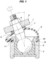
- a ball joint comprising a cover according to the present invention is structured such that a spherical head portion 2 formed in one end of a ball stud 1 is retained within a socket 3, a shaft 4 in the other end of the ball stud 1 is fastened and fixed to a knuckle 5, a one end large-diameter opening portion 8 is fixed and retained to an outer peripheral surface of the socket 3, and the other end small-diameter portion 7 embedding a reinforcing ring 9 therein is retained to the shaft 4.
- the reinforcing ring 9 is constructed by a tubular portion 91, and a flange portion 92 which extends from an end portion in a side of the knuckle 5 of the tubular portion 91 toward the shaft 4.
- the reinforcing ring 9 is integrated with the small-diameter portion 7 in such a manner that a side surface 921 in the side of the knuckle 5 of the flange portion 92 and an inner peripheral surface 922 of the flange portion 92 facing to a peripheral surface of the shaft 4 are exposed.
- an inward end portion 923 in a diametrical direction of the flange portion 92 protrudes to the shaft 4 side, and engages with an annular step portion 41 which is provided in an outer peripheral surface of the shaft 4.
- the inward end portion 923 in the diametrical direction inhibits the displacement to the spherical head portion 2 side in cooperation with the step portion 41.
- the flange portion 92 of the reinforcing ring 9 is structured such as to extend toward the shaft 4, it is possible to more downsize the small-diameter portion 7. Therefore, it is possible to maintain the shape of the dust cover 6 in the bell shape, even in the case that the diameter difference between the ball stud 1 and the socket 3 is reduced.
- a plurality of projections 924 and 924 each having a circular arc shape are uniformly provided in an inner peripheral surface 922 which comes into contact with an outer peripheral surface of the shaft 4 in the inward end portion 923 in the diametrical direction of the reinforcing ring 9. Therefore, it is possible to reduce a sliding resistance between the ball stud 1 and the reinforcing ring 9. As a result, it is possible to inhibit the buckling (the torsion) of the film portion of the dust cover 6 from being generated.
- the present embodiment is structured such that twelve projections 924 each having the circular arc shape are uniformly provided, however, the number of the projections 924 is three or more. Further, the projection may be formed as a triangular shape or a quadrangular shape in addition to the circular arc shape, and various shapes can be applied as long as a contact way with the outer peripheral surface of the shaft 4 is similar to a line contact or a point contact and can reduce the sliding resistance.
- an inner diameter of a root portion 925 existing between the projections 924 and 924 is designed into such a dimension as to prevent the metal mold from coming into contact with a whole surface of the flange portion 92 and prevent the elastic member from leaking out to the side surface 921 side via the root portion 925, in the case that the seal lip 72 is integrally formed in the flange portion 92 of the reinforcing ring 9.
- the shape of the dust cover 6 can be maintained in the bell shape, it is possible to dissolve the tendency that the strain applied to the film portion of the dust cover 6 is enlarged. As a result, it is possible to improve a durability of the dust cover 6, and it is possible to avoid a problem that a part on the circumference of the film portion of the dust cover deforms to an inner diameter side when setting the dust cover.
- the reinforcing ring 9 is integrated with the small-diameter portion 7 in such a manner that the side surface 921 in the knuckle 5 side of the flange portion 92 and the inner peripheral surface 922 facing to the peripheral surface of the shaft 4 in the flange portion 92 are exposed, it is possible to more downsize the small-diameter portion 7.
- the reinforcing ring 9 is manufactured by a punching work from a steel plate such as SPCC.
- the reinforcing ring 9 can be made thinner in comparison with the case that the resin material is used, it is more possible to maintain the shape of the dust cover 6 in the bell shape, even in the case that the diameter difference between the ball stud 1 and the socket 3 is reduced.
- a material of the dust cover 6 is used by appropriately selecting from a rubber-like material such as chloroprene, and a thermoplastic elastomer such as a polyester elastomer and a thermoplastic polyurethane according to an intended use.
- a different point from the previously described embodiment is provision of a pin groove 61 for a ring receiving pin, the pin groove 61 supporting the end portion in the spherical head portion 2 side of the tubular portion 91, in place of the protrusion of the inward end portion 923 of the flange portion 92 to the shaft 4 side.
- the one end large-diameter opening portion 8 having an approximately C-shaped cross section in the dust cover 6 made of the rubber-like elastic material is structured such as to be fixed and retained within an annular groove portion 31 which is formed in the outer peripheral surface of the socket 3, by the annular pressure ring 11.
- a circlip having an approximately rectangular cross sectional shape is used as the pressure ring 11.
- a dust lip 71 coming into elastic contact with the knuckle 5 is provided, and a seal lip 72 coming into elastic contact with the outer peripheral surface of the shaft 4 is formed.
- the present invention can be used in the ball joint which is used in the suspension device and the steering device of the motor vehicle.
Description
- The present invention relates to a ball joint comprising a dust cover.
- Further, the present invention relates to a ball joint comprising a dust cover which is used in an automobile suspension device, and a steering device.
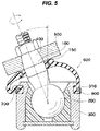
- Conventionally, as a ball joint to which a dust cover is installed for the purpose of a dust prevention and a water prevention in a ball joint coupling portion, there has been known a ball joint dust cover which is described in
Fig. 5 (JP S62 137 408 A - In a seal structure of this kind of ball joint dust cover, a
spherical head portion 200 formed in one end of aball stud 100 is retained within asocket 300. - Further, a
shaft 400 in the other end of theball stud 100 is fastened and fixed to aknuckle 500. - On the other hand, a one end large-
diameter opening portion 800 formed as an approximately C-shaped cross sectional form of adust cover 600 made of a rubber-like elastic material is fixed and retained within anannular groove portion 310 which is formed in an outer peripheral surface of thesocket 300 by anannular pressure ring 700, and the other end small-diameter opening portion 150 is retained to theshaft 400. - The
pressure ring 700 employs a circlip which is formed approximately as a rectangular cross sectional shape. - In this kind of
conventional dust cover 600, in the case that theball stud 100 oscillates in a state in which theball stud 100 is inclined as shown inFig. 5 , a force extending the small-diameter portion 150 is applied in a side in which a film portion of thedust cover 600 extends (a right side on the drawing). Therefore, there is generated a so-called mouth opening phenomenon of the small-diameter portion 150 in which a lip portion of the small-diameter portion 150 and theknuckle 500 is disconnected. - As a result, a seal performance in the small-
diameter portion 150 is lowered, and a problem that sedimentation or garbage enters into thedust cover 600 from an external portion has been brought about. - Further, it is often the case that the general dust cover has a bell shape as shown in
Fig. 4 , however, in the case that a diameter difference between the ball stud and the socket is reduced for the reason of downsizing of the socket, there has been generated a case that it is necessary to set the shape of the dust cover to a shape similar to a cylindrical shape in place of the bell shape. - As mentioned above, there is a tendency that the closer to the cylindrical shape the shape of the dust cover is, the greater a strain applied to the film portion of the dust cover is.
- As a result, a durability of the dust cover is lowered, thereby causing a problem that a part on a circumference of the film portion of the dust cover deforms to an inner diameter side at the setting time of the dust cover. Further, a problem that the small-diameter portion of the dust cover falls away from the ball stud has been brought about.
- Therefore, it is desired for the shape of the dust cover to maintain the bell shape even if the diameter difference between the ball stud and the socket is reduced.
- Furthermore, a ball joint comprising a dust cover according to the preamble of
claim 1 is known fromDE 20 2005 002 407 U1 . Further ball joint dust covers are disclosed inEP 0 916 859 A2 andJP S61 175 667 U1 - The present invention is made by taking the problem mentioned above into consideration, and an object of the present invention is to provide a ball joint dust cover which can maintain a shape of a dust cover in a bell shape even in the case that a diameter difference between a ball stud and a socket is reduced, can resolve the problem that the small-diameter portion of the dust cover falls away from the ball stud, and has a good durability.
- According to the present invention, the above object is solved with a ball joint having the features of
claim 1. - The present invention achieves effects as described below.
- According to the ball joint comprising a dust cover of the invention as defined in
claim 1, even if a diameter difference between the ball stud and the socket becomes smaller, it is possible to maintain the shape of the dust cover in the bell shape, it is possible to resolve the problem that the small-diameter portion of the dust cover falls away from the ball stud, and a durability is good. - Further, according to the ball joint comprising a dust cover of the invention as defined in
claim 1, it is possible to more securely resolve the problem that the small-diameter portion of the dust cover falls away from the ball stud. Further, since the reinforcing ring can be positioned by the inward end portion in the diametrical direction of the flange portion at the molding time, it is not necessary to set the ring receiving pin in the metal mold, and it is possible to reduce a working man hour of the metal mold. Further, since a plurality of projections are uniformly provided in the inner peripheral surface which comes into contact with the axial outer peripheral surface of the inward end portion in the diametrical direction, it is possible to reduce a sliding resistance between the ball stud and the reinforcing ring. As a result, it is possible to inhibit buckling (torsion) of the dust cover film portion from being generated. - Further, according to the ball joint comprising a dust cover of the invention as defined in
claim 2, since the reinforcing ring can be made thinner, it is possible to maintain the shape of the dust cover in the bell shape even if the diameter difference between the ball stud and the socket becomes smaller. -
-
Fig. 1 is a vertical cross sectional view of a ball joint comprising a dust cover according to the present invention; -
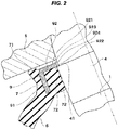
Fig. 2 is a partly enlarged view of a small-diameter portion of the ball joint comprising a dust cover inFig. 1 ; -
Fig. 3 is a plan view of a reinforcing ring shown inFig. 2 ; -
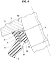
Fig. 4 is a view showing a ball joint comprising a cover not according to the present invention in the same manner asFig. 2 ; and -
Fig. 5 is a vertical cross sectional view of a ball joint comprising a dust cover according to a prior art. - A description will be given below of a mode for carrying out the present invention.
- As shown in
Figs. 1 ,2 and3 , a ball joint comprising a cover according to the present invention is structured such that aspherical head portion 2 formed in one end of aball stud 1 is retained within asocket 3, ashaft 4 in the other end of theball stud 1 is fastened and fixed to aknuckle 5, a one end large-diameter opening portion 8 is fixed and retained to an outer peripheral surface of thesocket 3, and
the other end small-diameter portion 7 embedding a reinforcingring 9 therein is retained to theshaft 4. - Further, the
reinforcing ring 9 is constructed by atubular portion 91, and aflange portion 92 which extends from an end portion in a side of theknuckle 5 of thetubular portion 91 toward theshaft 4. - Further, the reinforcing
ring 9 is integrated with the small-diameter portion 7 in such a manner that aside surface 921 in the side of theknuckle 5 of theflange portion 92 and an innerperipheral surface 922 of theflange portion 92 facing to a peripheral surface of theshaft 4 are exposed. - Further, an
inward end portion 923 in a diametrical direction of theflange portion 92 protrudes to theshaft 4 side, and engages with anannular step portion 41 which is provided in an outer peripheral surface of theshaft 4. - Accordingly, even if the small-
diameter portion 7 is pulled to thespherical head portion 2 side (a downward side on the drawing) by the film portion of thedust cover 6, theinward end portion 923 in the diametrical direction inhibits the displacement to thespherical head portion 2 side in cooperation with thestep portion 41. - Further, since the
flange portion 92 of the reinforcingring 9 is structured such as to extend toward theshaft 4, it is possible to more downsize the small-diameter portion 7. Therefore, it is possible to maintain the shape of thedust cover 6 in the bell shape, even in the case that the diameter difference between theball stud 1 and thesocket 3 is reduced. - Further, a plurality of
projections peripheral surface 922 which comes into contact with an outer peripheral surface of theshaft 4 in theinward end portion 923 in the diametrical direction of the reinforcingring 9. Therefore, it is possible to reduce a sliding resistance between theball stud 1 and the reinforcingring 9. As a result, it is possible to inhibit the buckling (the torsion) of the film portion of thedust cover 6 from being generated. - The present embodiment is structured such that twelve
projections 924 each having the circular arc shape are uniformly provided, however, the number of theprojections 924 is three or more. Further, the projection may be formed as a triangular shape or a quadrangular shape in addition to the circular arc shape, and various shapes can be applied as long as a contact way with the outer peripheral surface of theshaft 4 is similar to a line contact or a point contact and can reduce the sliding resistance. - Further, an inner diameter of a
root portion 925 existing between theprojections flange portion 92 and prevent the elastic member from leaking out to theside surface 921 side via theroot portion 925, in the case that theseal lip 72 is integrally formed in theflange portion 92 of the reinforcingring 9. - Specifically, it is desirable to form such a shape that the
root portion 925 is accommodated within thestep portion 41. - Further, since the shape of the
dust cover 6 can be maintained in the bell shape, it is possible to dissolve the tendency that the strain applied to the film portion of thedust cover 6 is enlarged. As a result, it is possible to improve a durability of thedust cover 6, and it is possible to avoid a problem that a part on the circumference of the film portion of the dust cover deforms to an inner diameter side when setting the dust cover. - Further, since the reinforcing
ring 9 is integrated with the small-diameter portion 7 in such a manner that theside surface 921 in theknuckle 5 side of theflange portion 92 and the innerperipheral surface 922 facing to the peripheral surface of theshaft 4 in theflange portion 92 are exposed, it is possible to more downsize the small-diameter portion 7. - Further, a grease is sealed within the
dust cover 6. - The reinforcing
ring 9 is manufactured by a punching work from a steel plate such as SPCC. - Therefore, since the reinforcing
ring 9 can be made thinner in comparison with the case that the resin material is used, it is more possible to maintain the shape of thedust cover 6 in the bell shape, even in the case that the diameter difference between theball stud 1 and thesocket 3 is reduced. - Further, a material of the
dust cover 6 is used by appropriately selecting from a rubber-like material such as chloroprene, and a thermoplastic elastomer such as a polyester elastomer and a thermoplastic polyurethane according to an intended use. - Next, a description will be given of another aspect of the ball joint comprising a dust cover not according to the present invention with reference to
Fig. 4 . - A different point from the previously described embodiment is provision of a
pin groove 61 for a ring receiving pin, thepin groove 61 supporting the end portion in thespherical head portion 2 side of thetubular portion 91, in place of the protrusion of theinward end portion 923 of theflange portion 92 to theshaft 4 side. - According to the structure mentioned above, it is possible to maintain the shape of the
dust cover 6 in the bell shape even in the case that thestep portion 41 is not provided in the outer peripheral surface of theshaft 4. - Further, the grease is sealed within the
dust cover 6. - On the other hand, the one end large-
diameter opening portion 8 having an approximately C-shaped cross section in thedust cover 6 made of the rubber-like elastic material is structured such as to be fixed and retained within anannular groove portion 31 which is formed in the outer peripheral surface of thesocket 3, by theannular pressure ring 11. - As the
pressure ring 11, a circlip having an approximately rectangular cross sectional shape is used. - Further, in the small-
diameter portion 7, adust lip 71 coming into elastic contact with theknuckle 5 is provided, and aseal lip 72 coming into elastic contact with the outer peripheral surface of theshaft 4 is formed. - As a result, it is possible to more effectively inhibit the dust from intruding into the
dust cover 6 from the external portion, and it is possible to prevent the grease from flowing out of an inner side of thedust cover 6. - Further, it goes without saying that the present invention is not limited to the best mode for carrying out the invention mentioned above, but can employ the other various structures without deviating from the scope of the appended claims. invention defined by the appended claims only.
- The present invention can be used in the ball joint which is used in the suspension device and the steering device of the motor vehicle.
-
- 1
- ball stud
- 2
- spherical head portion
- 3
- socket
- 4
- shaft
- 5
- knuckle
- 6
- dust cover
- 7
- small-diameter portion
- 8
- large-diameter opening portion
- 9
- reinforcing ring
- 11
- pressure ring
- 31
- groove portion
- 41
- step portion
- 71
- dust lip
- 72
- seal lip
- 91
- tubular portion
- 92
- flange portion
- 921
- side surface
- 922
- inner peripheral surface
- 923
- inward end portion
- 924
- projection
- 925
- root portion
Claims (2)
- A ball joint having a spherical head portion (2) formed in one end of a ball stud (1) and retained within a socket (3), a shaft (4) in the other end of said ball stud (1), which is fastened and fixed to a knuckle (5), and a ball joint dust cover (6), wherein a one end large-diameter opening portion (8) of the ball joint dust cover (6) is fixed and retained to an outer peripheral surface of said socket (3), wherein the other end small-diameter portion (7) of the ball joint dust cover (6), which is embedding a reinforcing ring (9) therein, is retained to said shaft (4), and wherein said ball joint dust cover (6) is made of an elastic material,
wherein said reinforcing ring (9) is constructed by a tubular portion (91), and a flange portion (92) which extends from an end portion in a side of said knuckle (5) in said tubular portion (91) toward said shaft (4), and is integrated with said small-diameter portion (7) in such a manner that a side surface (921) of said flange portion (92) in a side of said knuckle (5) and an inner peripheral surface (922) of said flange portion (92) facing to a peripheral surface of said shaft (4) are exposed, wherein
in the small-diameter portion (7), a seal lip (72) coming into elastic contact with the outer peripheral surface of the shaft (4) is formed, characterized in that
in the small-diameter portion (7), a dust lip (71) coming into elastic contact with the knuckle (5) is provided, and
an inward end portion (923) in a diametrical direction of said flange portion (92) engages with a step portion (41) provided in an outer peripheral surface of said shaft (4) as well as protruding to said shaft (4) side, and a plurality of projections (924) are uniformly provided in said inner peripheral surface (922) which come into contact with the outer peripheral surface of said shaft (4) in said inward end portion (923) in the diametrical direction. - The ball joint dust cover according to claim 1, wherein said reinforcing ring (9) is made of a metal material.
Applications Claiming Priority (3)
| Application Number | Priority Date | Filing Date | Title |
|---|---|---|---|
| JP2012020433 | 2012-02-02 | ||
| JP2012162226A JP6025024B2 (en) | 2012-02-02 | 2012-07-23 | Dust cover for ball joint |
| PCT/JP2013/050516 WO2013114938A1 (en) | 2012-02-02 | 2013-01-15 | Ball joint dust cover |
Publications (3)
| Publication Number | Publication Date |
|---|---|
| EP2811184A1 EP2811184A1 (en) | 2014-12-10 |
| EP2811184A4 EP2811184A4 (en) | 2016-01-06 |
| EP2811184B1 true EP2811184B1 (en) | 2018-08-22 |
Family
ID=48904981
Family Applications (1)
| Application Number | Title | Priority Date | Filing Date |
|---|---|---|---|
| EP13743519.4A Not-in-force EP2811184B1 (en) | 2012-02-02 | 2013-01-15 | Ball joint dust cover |
Country Status (5)
| Country | Link |
|---|---|
| US (1) | US9206837B2 (en) |
| EP (1) | EP2811184B1 (en) |
| JP (1) | JP6025024B2 (en) |
| CN (1) | CN104040195B (en) |
| WO (1) | WO2013114938A1 (en) |
Families Citing this family (9)
| Publication number | Priority date | Publication date | Assignee | Title |
|---|---|---|---|---|
| JP5888577B1 (en) * | 2014-05-13 | 2016-03-22 | Nok株式会社 | Dust cover for ball joint |
| JP6135828B2 (en) * | 2014-10-22 | 2017-05-31 | Nok株式会社 | Dust cover |
| US9790983B2 (en) * | 2015-05-21 | 2017-10-17 | Federal-Mogul Motorparts Corporation | Movable joint assembly |
| JP6167256B1 (en) * | 2015-11-20 | 2017-07-19 | Nok株式会社 | Dust cover for ball joint and method of attaching dust cover for ball joint |
| DE102015224616A1 (en) * | 2015-12-08 | 2017-06-08 | Robert Bosch Gmbh | Method for fastening a spherical shell in a joint rod and joint rod with ball socket |
| JP6387206B2 (en) * | 2016-09-21 | 2018-09-05 | Nok株式会社 | Dust cover |
| EP3306143B1 (en) * | 2016-10-04 | 2020-09-02 | Fico Triad, S.A. | Gear shift device for motor vehicles |
| EP3427904B1 (en) * | 2017-07-13 | 2020-06-10 | Siemens Aktiengesellschaft | Assembly with a manipulator and a limiting device for limiting the working space |
| DE102019110034A1 (en) * | 2019-04-16 | 2020-10-22 | Carl Freudenberg Kg | Sealing bellows |
Family Cites Families (20)
| Publication number | Priority date | Publication date | Assignee | Title |
|---|---|---|---|---|
| US3248955A (en) * | 1962-06-29 | 1966-05-03 | Trw Inc | Pressure relief boot seal |
| US4322175A (en) * | 1980-05-12 | 1982-03-30 | Trw Inc. | Joint assembly |
| JPS60103766U (en) * | 1983-12-22 | 1985-07-15 | 豊田合成株式会社 | dust cover |
| JPS61175667U (en) * | 1985-04-22 | 1986-11-01 | ||
| JPH0135062Y2 (en) * | 1985-06-03 | 1989-10-25 | ||
| JPS62137408A (en) | 1985-12-11 | 1987-06-20 | Musashi Seimitsu Ind Co Ltd | Dust cover for ball joint |
| JPS6388378A (en) * | 1986-09-30 | 1988-04-19 | Toyoda Gosei Co Ltd | Dust cover |
| JPH02127816U (en) * | 1989-03-30 | 1990-10-22 | ||
| JPH078904Y2 (en) * | 1990-06-28 | 1995-03-06 | エヌオーケー株式会社 | Dust cover |
| DE4133878C2 (en) * | 1991-10-12 | 1995-04-13 | Continental Ag | Air spring with a hose bellows made of elastomeric material |
| JPH11141535A (en) * | 1997-11-11 | 1999-05-25 | Somic Ishikawa:Kk | Ball joint |
| DE19843063C1 (en) * | 1998-09-19 | 2000-10-26 | Zf Lemfoerder Metallwaren Ag | Bellows seal |
| DE10114693C2 (en) * | 2001-03-23 | 2003-02-27 | Zf Lemfoerder Metallwaren Ag | ball joint |
| DE10124295C5 (en) * | 2001-05-17 | 2008-09-04 | ZF Lemförder GmbH | ball joint |
| DE10239266B4 (en) * | 2002-08-22 | 2005-02-24 | ZF Lemförder Metallwaren AG | Ball joint with sealing bellows |
| DE202005002407U1 (en) * | 2005-02-15 | 2005-07-07 | Trw Automotive Gmbh | bellows |
| JP2007247824A (en) * | 2006-03-17 | 2007-09-27 | Nok Corp | Dust cover sealing structure for ball joint |
| JP5146646B2 (en) * | 2007-02-27 | 2013-02-20 | Nok株式会社 | Dust cover fixing structure |
| JP2008232249A (en) * | 2007-03-20 | 2008-10-02 | Nok Corp | Dust cover fixing structure |
| JP2008240865A (en) * | 2007-03-27 | 2008-10-09 | Nok Corp | Fixing structure of dust cover |
-
2012
- 2012-07-23 JP JP2012162226A patent/JP6025024B2/en active Active
-
2013
- 2013-01-15 WO PCT/JP2013/050516 patent/WO2013114938A1/en active Application Filing
- 2013-01-15 US US14/371,576 patent/US9206837B2/en not_active Expired - Fee Related
- 2013-01-15 EP EP13743519.4A patent/EP2811184B1/en not_active Not-in-force
- 2013-01-15 CN CN201380004741.0A patent/CN104040195B/en not_active Expired - Fee Related
Also Published As
| Publication number | Publication date |
|---|---|
| WO2013114938A1 (en) | 2013-08-08 |
| JP2013177957A (en) | 2013-09-09 |
| CN104040195A (en) | 2014-09-10 |
| US20150003893A1 (en) | 2015-01-01 |
| EP2811184A1 (en) | 2014-12-10 |
| EP2811184A4 (en) | 2016-01-06 |
| US9206837B2 (en) | 2015-12-08 |
| JP6025024B2 (en) | 2016-11-16 |
| CN104040195B (en) | 2016-06-29 |
Similar Documents
| Publication | Publication Date | Title |
|---|---|---|
| EP2811184B1 (en) | Ball joint dust cover | |
| EP2088352B1 (en) | Sealing device | |
| EP2184519B1 (en) | Sealing device | |
| EP2012028B1 (en) | Dust cover for ball joint | |
| WO2011033867A1 (en) | Dust cover for ball joint | |
| EP3144549A1 (en) | Dust cover for ball joint | |
| JPWO2006049152A1 (en) | Bearing seal | |
| EP3106687B1 (en) | Dust cover for ball joint | |
| EP2778446A1 (en) | Dust cover for ball joint | |
| JP5057219B2 (en) | Dust cover for ball joint | |
| EP3006749B1 (en) | Ball joint dust cover | |
| EP3015725B1 (en) | Ball joint dust cover | |
| JP2013160327A (en) | Dust cover for ball joint | |
| EP2937581B1 (en) | Ball joint dust cover | |
| JP5073319B2 (en) | Constant velocity joint boots | |
| JP2012097855A (en) | Dust cover for ball joint | |
| EP2796735A1 (en) | Dust cover for ball joint | |
| JP2013160326A (en) | Dust cover for ball joint | |
| JP2008232249A (en) | Dust cover fixing structure | |
| JP2012127437A (en) | Dust cover for ball joint | |
| EP4027041A1 (en) | Sealing device | |
| JP2018025202A (en) | Dust cover and ball joint | |
| JP2012092858A (en) | Dust cover for ball joint | |
| JP2012087840A (en) | Dust cover for ball joint |
Legal Events
| Date | Code | Title | Description |
|---|---|---|---|
| PUAI | Public reference made under article 153(3) epc to a published international application that has entered the european phase |
Free format text: ORIGINAL CODE: 0009012 |
|
| 17P | Request for examination filed |
Effective date: 20140702 |
|
| AK | Designated contracting states |
Kind code of ref document: A1 Designated state(s): AL AT BE BG CH CY CZ DE DK EE ES FI FR GB GR HR HU IE IS IT LI LT LU LV MC MK MT NL NO PL PT RO RS SE SI SK SM TR |
|
| AX | Request for extension of the european patent |
Extension state: BA ME |
|
| DAX | Request for extension of the european patent (deleted) | ||
| RA4 | Supplementary search report drawn up and despatched (corrected) |
Effective date: 20151207 |
|
| RIC1 | Information provided on ipc code assigned before grant |
Ipc: F16J 15/52 20060101ALI20151201BHEP Ipc: F16C 11/06 20060101AFI20151201BHEP |
|
| STAA | Information on the status of an ep patent application or granted ep patent |
Free format text: STATUS: EXAMINATION IS IN PROGRESS |
|
| 17Q | First examination report despatched |
Effective date: 20170719 |
|
| GRAP | Despatch of communication of intention to grant a patent |
Free format text: ORIGINAL CODE: EPIDOSNIGR1 |
|
| STAA | Information on the status of an ep patent application or granted ep patent |
Free format text: STATUS: GRANT OF PATENT IS INTENDED |
|
| INTG | Intention to grant announced |
Effective date: 20180308 |
|
| RIN1 | Information on inventor provided before grant (corrected) |
Inventor name: KANAGAWA, KOJI Inventor name: SATO, NORIAKI Inventor name: ISHIMORI, JUNICHI |
|
| GRAS | Grant fee paid |
Free format text: ORIGINAL CODE: EPIDOSNIGR3 |
|
| GRAA | (expected) grant |
Free format text: ORIGINAL CODE: 0009210 |
|
| STAA | Information on the status of an ep patent application or granted ep patent |
Free format text: STATUS: THE PATENT HAS BEEN GRANTED |
|
| AK | Designated contracting states |
Kind code of ref document: B1 Designated state(s): AL AT BE BG CH CY CZ DE DK EE ES FI FR GB GR HR HU IE IS IT LI LT LU LV MC MK MT NL NO PL PT RO RS SE SI SK SM TR |
|
| REG | Reference to a national code |
Ref country code: GB Ref legal event code: FG4D |
|
| REG | Reference to a national code |
Ref country code: CH Ref legal event code: EP |
|
| REG | Reference to a national code |
Ref country code: AT Ref legal event code: REF Ref document number: 1032873 Country of ref document: AT Kind code of ref document: T Effective date: 20180915 |
|
| REG | Reference to a national code |
Ref country code: IE Ref legal event code: FG4D |
|
| REG | Reference to a national code |
Ref country code: DE Ref legal event code: R096 Ref document number: 602013042398 Country of ref document: DE |
|
| REG | Reference to a national code |
Ref country code: NL Ref legal event code: MP Effective date: 20180822 |
|
| REG | Reference to a national code |
Ref country code: LT Ref legal event code: MG4D |
|
| PG25 | Lapsed in a contracting state [announced via postgrant information from national office to epo] |
Ref country code: NO Free format text: LAPSE BECAUSE OF FAILURE TO SUBMIT A TRANSLATION OF THE DESCRIPTION OR TO PAY THE FEE WITHIN THE PRESCRIBED TIME-LIMIT Effective date: 20181122 Ref country code: SE Free format text: LAPSE BECAUSE OF FAILURE TO SUBMIT A TRANSLATION OF THE DESCRIPTION OR TO PAY THE FEE WITHIN THE PRESCRIBED TIME-LIMIT Effective date: 20180822 Ref country code: RS Free format text: LAPSE BECAUSE OF FAILURE TO SUBMIT A TRANSLATION OF THE DESCRIPTION OR TO PAY THE FEE WITHIN THE PRESCRIBED TIME-LIMIT Effective date: 20180822 Ref country code: GR Free format text: LAPSE BECAUSE OF FAILURE TO SUBMIT A TRANSLATION OF THE DESCRIPTION OR TO PAY THE FEE WITHIN THE PRESCRIBED TIME-LIMIT Effective date: 20181123 Ref country code: FI Free format text: LAPSE BECAUSE OF FAILURE TO SUBMIT A TRANSLATION OF THE DESCRIPTION OR TO PAY THE FEE WITHIN THE PRESCRIBED TIME-LIMIT Effective date: 20180822 Ref country code: IS Free format text: LAPSE BECAUSE OF FAILURE TO SUBMIT A TRANSLATION OF THE DESCRIPTION OR TO PAY THE FEE WITHIN THE PRESCRIBED TIME-LIMIT Effective date: 20181222 Ref country code: BG Free format text: LAPSE BECAUSE OF FAILURE TO SUBMIT A TRANSLATION OF THE DESCRIPTION OR TO PAY THE FEE WITHIN THE PRESCRIBED TIME-LIMIT Effective date: 20181122 Ref country code: NL Free format text: LAPSE BECAUSE OF FAILURE TO SUBMIT A TRANSLATION OF THE DESCRIPTION OR TO PAY THE FEE WITHIN THE PRESCRIBED TIME-LIMIT Effective date: 20180822 Ref country code: LT Free format text: LAPSE BECAUSE OF FAILURE TO SUBMIT A TRANSLATION OF THE DESCRIPTION OR TO PAY THE FEE WITHIN THE PRESCRIBED TIME-LIMIT Effective date: 20180822 |
|
| REG | Reference to a national code |
Ref country code: AT Ref legal event code: MK05 Ref document number: 1032873 Country of ref document: AT Kind code of ref document: T Effective date: 20180822 |
|
| PG25 | Lapsed in a contracting state [announced via postgrant information from national office to epo] |
Ref country code: AL Free format text: LAPSE BECAUSE OF FAILURE TO SUBMIT A TRANSLATION OF THE DESCRIPTION OR TO PAY THE FEE WITHIN THE PRESCRIBED TIME-LIMIT Effective date: 20180822 Ref country code: LV Free format text: LAPSE BECAUSE OF FAILURE TO SUBMIT A TRANSLATION OF THE DESCRIPTION OR TO PAY THE FEE WITHIN THE PRESCRIBED TIME-LIMIT Effective date: 20180822 Ref country code: HR Free format text: LAPSE BECAUSE OF FAILURE TO SUBMIT A TRANSLATION OF THE DESCRIPTION OR TO PAY THE FEE WITHIN THE PRESCRIBED TIME-LIMIT Effective date: 20180822 |
|
| PG25 | Lapsed in a contracting state [announced via postgrant information from national office to epo] |
Ref country code: EE Free format text: LAPSE BECAUSE OF FAILURE TO SUBMIT A TRANSLATION OF THE DESCRIPTION OR TO PAY THE FEE WITHIN THE PRESCRIBED TIME-LIMIT Effective date: 20180822 Ref country code: PL Free format text: LAPSE BECAUSE OF FAILURE TO SUBMIT A TRANSLATION OF THE DESCRIPTION OR TO PAY THE FEE WITHIN THE PRESCRIBED TIME-LIMIT Effective date: 20180822 Ref country code: AT Free format text: LAPSE BECAUSE OF FAILURE TO SUBMIT A TRANSLATION OF THE DESCRIPTION OR TO PAY THE FEE WITHIN THE PRESCRIBED TIME-LIMIT Effective date: 20180822 Ref country code: RO Free format text: LAPSE BECAUSE OF FAILURE TO SUBMIT A TRANSLATION OF THE DESCRIPTION OR TO PAY THE FEE WITHIN THE PRESCRIBED TIME-LIMIT Effective date: 20180822 Ref country code: ES Free format text: LAPSE BECAUSE OF FAILURE TO SUBMIT A TRANSLATION OF THE DESCRIPTION OR TO PAY THE FEE WITHIN THE PRESCRIBED TIME-LIMIT Effective date: 20180822 Ref country code: CZ Free format text: LAPSE BECAUSE OF FAILURE TO SUBMIT A TRANSLATION OF THE DESCRIPTION OR TO PAY THE FEE WITHIN THE PRESCRIBED TIME-LIMIT Effective date: 20180822 Ref country code: IT Free format text: LAPSE BECAUSE OF FAILURE TO SUBMIT A TRANSLATION OF THE DESCRIPTION OR TO PAY THE FEE WITHIN THE PRESCRIBED TIME-LIMIT Effective date: 20180822 |
|
| REG | Reference to a national code |
Ref country code: DE Ref legal event code: R097 Ref document number: 602013042398 Country of ref document: DE |
|
| PG25 | Lapsed in a contracting state [announced via postgrant information from national office to epo] |
Ref country code: SK Free format text: LAPSE BECAUSE OF FAILURE TO SUBMIT A TRANSLATION OF THE DESCRIPTION OR TO PAY THE FEE WITHIN THE PRESCRIBED TIME-LIMIT Effective date: 20180822 Ref country code: SM Free format text: LAPSE BECAUSE OF FAILURE TO SUBMIT A TRANSLATION OF THE DESCRIPTION OR TO PAY THE FEE WITHIN THE PRESCRIBED TIME-LIMIT Effective date: 20180822 Ref country code: DK Free format text: LAPSE BECAUSE OF FAILURE TO SUBMIT A TRANSLATION OF THE DESCRIPTION OR TO PAY THE FEE WITHIN THE PRESCRIBED TIME-LIMIT Effective date: 20180822 |
|
| PLBE | No opposition filed within time limit |
Free format text: ORIGINAL CODE: 0009261 |
|
| STAA | Information on the status of an ep patent application or granted ep patent |
Free format text: STATUS: NO OPPOSITION FILED WITHIN TIME LIMIT |
|
| 26N | No opposition filed |
Effective date: 20190523 |
|
| PG25 | Lapsed in a contracting state [announced via postgrant information from national office to epo] |
Ref country code: MC Free format text: LAPSE BECAUSE OF FAILURE TO SUBMIT A TRANSLATION OF THE DESCRIPTION OR TO PAY THE FEE WITHIN THE PRESCRIBED TIME-LIMIT Effective date: 20180822 Ref country code: SI Free format text: LAPSE BECAUSE OF FAILURE TO SUBMIT A TRANSLATION OF THE DESCRIPTION OR TO PAY THE FEE WITHIN THE PRESCRIBED TIME-LIMIT Effective date: 20180822 |
|
| REG | Reference to a national code |
Ref country code: CH Ref legal event code: PL |
|
| PG25 | Lapsed in a contracting state [announced via postgrant information from national office to epo] |
Ref country code: LU Free format text: LAPSE BECAUSE OF NON-PAYMENT OF DUE FEES Effective date: 20190115 |
|
| REG | Reference to a national code |
Ref country code: BE Ref legal event code: MM Effective date: 20190131 |
|
| REG | Reference to a national code |
Ref country code: IE Ref legal event code: MM4A |
|
| PG25 | Lapsed in a contracting state [announced via postgrant information from national office to epo] |
Ref country code: BE Free format text: LAPSE BECAUSE OF NON-PAYMENT OF DUE FEES Effective date: 20190131 |
|
| PG25 | Lapsed in a contracting state [announced via postgrant information from national office to epo] |
Ref country code: CH Free format text: LAPSE BECAUSE OF NON-PAYMENT OF DUE FEES Effective date: 20190131 Ref country code: LI Free format text: LAPSE BECAUSE OF NON-PAYMENT OF DUE FEES Effective date: 20190131 |
|
| PG25 | Lapsed in a contracting state [announced via postgrant information from national office to epo] |
Ref country code: IE Free format text: LAPSE BECAUSE OF NON-PAYMENT OF DUE FEES Effective date: 20190115 |
|
| PG25 | Lapsed in a contracting state [announced via postgrant information from national office to epo] |
Ref country code: TR Free format text: LAPSE BECAUSE OF FAILURE TO SUBMIT A TRANSLATION OF THE DESCRIPTION OR TO PAY THE FEE WITHIN THE PRESCRIBED TIME-LIMIT Effective date: 20180822 |
|
| PG25 | Lapsed in a contracting state [announced via postgrant information from national office to epo] |
Ref country code: MT Free format text: LAPSE BECAUSE OF NON-PAYMENT OF DUE FEES Effective date: 20190115 Ref country code: PT Free format text: LAPSE BECAUSE OF FAILURE TO SUBMIT A TRANSLATION OF THE DESCRIPTION OR TO PAY THE FEE WITHIN THE PRESCRIBED TIME-LIMIT Effective date: 20181222 |
|
| PGFP | Annual fee paid to national office [announced via postgrant information from national office to epo] |
Ref country code: FR Payment date: 20201210 Year of fee payment: 9 |
|
| PG25 | Lapsed in a contracting state [announced via postgrant information from national office to epo] |
Ref country code: CY Free format text: LAPSE BECAUSE OF FAILURE TO SUBMIT A TRANSLATION OF THE DESCRIPTION OR TO PAY THE FEE WITHIN THE PRESCRIBED TIME-LIMIT Effective date: 20180822 |
|
| PGFP | Annual fee paid to national office [announced via postgrant information from national office to epo] |
Ref country code: GB Payment date: 20210106 Year of fee payment: 9 Ref country code: DE Payment date: 20210105 Year of fee payment: 9 |
|
| PG25 | Lapsed in a contracting state [announced via postgrant information from national office to epo] |
Ref country code: HU Free format text: LAPSE BECAUSE OF FAILURE TO SUBMIT A TRANSLATION OF THE DESCRIPTION OR TO PAY THE FEE WITHIN THE PRESCRIBED TIME-LIMIT; INVALID AB INITIO Effective date: 20130115 |
|
| PG25 | Lapsed in a contracting state [announced via postgrant information from national office to epo] |
Ref country code: MK Free format text: LAPSE BECAUSE OF FAILURE TO SUBMIT A TRANSLATION OF THE DESCRIPTION OR TO PAY THE FEE WITHIN THE PRESCRIBED TIME-LIMIT Effective date: 20180822 |
|
| REG | Reference to a national code |
Ref country code: DE Ref legal event code: R119 Ref document number: 602013042398 Country of ref document: DE |
|
| GBPC | Gb: european patent ceased through non-payment of renewal fee |
Effective date: 20220115 |
|
| PG25 | Lapsed in a contracting state [announced via postgrant information from national office to epo] |
Ref country code: GB Free format text: LAPSE BECAUSE OF NON-PAYMENT OF DUE FEES Effective date: 20220115 Ref country code: DE Free format text: LAPSE BECAUSE OF NON-PAYMENT OF DUE FEES Effective date: 20220802 |
|
| PG25 | Lapsed in a contracting state [announced via postgrant information from national office to epo] |
Ref country code: FR Free format text: LAPSE BECAUSE OF NON-PAYMENT OF DUE FEES Effective date: 20220131 |