EP2811138B1 - Vane coupling part structure and jet engine using same - Google Patents
Vane coupling part structure and jet engine using same Download PDFInfo
- Publication number
- EP2811138B1 EP2811138B1 EP13743758.8A EP13743758A EP2811138B1 EP 2811138 B1 EP2811138 B1 EP 2811138B1 EP 13743758 A EP13743758 A EP 13743758A EP 2811138 B1 EP2811138 B1 EP 2811138B1
- Authority
- EP
- European Patent Office
- Prior art keywords
- vane
- end portion
- support member
- jet engine
- pair
- Prior art date
- Legal status (The legal status is an assumption and is not a legal conclusion. Google has not performed a legal analysis and makes no representation as to the accuracy of the status listed.)
- Active
Links
- 230000008878 coupling Effects 0.000 title claims description 114
- 238000010168 coupling process Methods 0.000 title claims description 114
- 238000005859 coupling reaction Methods 0.000 title claims description 114
- 239000002131 composite material Substances 0.000 claims description 9
- 239000000853 adhesive Substances 0.000 claims description 8
- 230000001070 adhesive effect Effects 0.000 claims description 8
- 229910052751 metal Inorganic materials 0.000 claims description 8
- 239000002184 metal Substances 0.000 claims description 8
- 239000000835 fiber Substances 0.000 claims description 5
- 230000002787 reinforcement Effects 0.000 claims description 5
- 229920005989 resin Polymers 0.000 claims description 5
- 239000011347 resin Substances 0.000 claims description 5
- 229920001187 thermosetting polymer Polymers 0.000 claims description 5
- 229920005992 thermoplastic resin Polymers 0.000 claims description 4
- 230000009467 reduction Effects 0.000 description 10
- 239000000470 constituent Substances 0.000 description 9
- 239000000463 material Substances 0.000 description 9
- 229910000838 Al alloy Inorganic materials 0.000 description 8
- 239000007769 metal material Substances 0.000 description 5
- 229920000049 Carbon (fiber) Polymers 0.000 description 3
- 229910001069 Ti alloy Inorganic materials 0.000 description 3
- 239000004917 carbon fiber Substances 0.000 description 3
- 239000003822 epoxy resin Substances 0.000 description 3
- 230000006872 improvement Effects 0.000 description 3
- VNWKTOKETHGBQD-UHFFFAOYSA-N methane Chemical compound C VNWKTOKETHGBQD-UHFFFAOYSA-N 0.000 description 3
- 229920000647 polyepoxide Polymers 0.000 description 3
- 230000002265 prevention Effects 0.000 description 3
- KXGFMDJXCMQABM-UHFFFAOYSA-N 2-methoxy-6-methylphenol Chemical compound [CH]OC1=CC=CC([CH])=C1O KXGFMDJXCMQABM-UHFFFAOYSA-N 0.000 description 2
- 239000004696 Poly ether ether ketone Substances 0.000 description 2
- 239000004697 Polyetherimide Substances 0.000 description 2
- 239000004734 Polyphenylene sulfide Substances 0.000 description 2
- 229920006231 aramid fiber Polymers 0.000 description 2
- 230000000694 effects Effects 0.000 description 2
- 239000005007 epoxy-phenolic resin Substances 0.000 description 2
- 239000003365 glass fiber Substances 0.000 description 2
- 238000010030 laminating Methods 0.000 description 2
- 230000013011 mating Effects 0.000 description 2
- 238000000034 method Methods 0.000 description 2
- 229920001568 phenolic resin Polymers 0.000 description 2
- 229920002530 polyetherether ketone Polymers 0.000 description 2
- 229920001601 polyetherimide Polymers 0.000 description 2
- 229920001721 polyimide Polymers 0.000 description 2
- 239000009719 polyimide resin Substances 0.000 description 2
- 229920000069 polyphenylene sulfide Polymers 0.000 description 2
- 230000008569 process Effects 0.000 description 2
- 230000002708 enhancing effect Effects 0.000 description 1
- 239000000446 fuel Substances 0.000 description 1
- 230000004044 response Effects 0.000 description 1
- 125000006850 spacer group Chemical group 0.000 description 1
- 239000000126 substance Substances 0.000 description 1
- 210000002105 tongue Anatomy 0.000 description 1
Images

Classifications
-
- F—MECHANICAL ENGINEERING; LIGHTING; HEATING; WEAPONS; BLASTING
- F01—MACHINES OR ENGINES IN GENERAL; ENGINE PLANTS IN GENERAL; STEAM ENGINES
- F01D—NON-POSITIVE DISPLACEMENT MACHINES OR ENGINES, e.g. STEAM TURBINES
- F01D9/00—Stators
- F01D9/02—Nozzles; Nozzle boxes; Stator blades; Guide conduits, e.g. individual nozzles
- F01D9/04—Nozzles; Nozzle boxes; Stator blades; Guide conduits, e.g. individual nozzles forming ring or sector
- F01D9/042—Nozzles; Nozzle boxes; Stator blades; Guide conduits, e.g. individual nozzles forming ring or sector fixing blades to stators
-
- F—MECHANICAL ENGINEERING; LIGHTING; HEATING; WEAPONS; BLASTING
- F01—MACHINES OR ENGINES IN GENERAL; ENGINE PLANTS IN GENERAL; STEAM ENGINES
- F01D—NON-POSITIVE DISPLACEMENT MACHINES OR ENGINES, e.g. STEAM TURBINES
- F01D25/00—Component parts, details, or accessories, not provided for in, or of interest apart from, other groups
- F01D25/16—Arrangement of bearings; Supporting or mounting bearings in casings
- F01D25/162—Bearing supports
-
- F—MECHANICAL ENGINEERING; LIGHTING; HEATING; WEAPONS; BLASTING
- F01—MACHINES OR ENGINES IN GENERAL; ENGINE PLANTS IN GENERAL; STEAM ENGINES
- F01D—NON-POSITIVE DISPLACEMENT MACHINES OR ENGINES, e.g. STEAM TURBINES
- F01D5/00—Blades; Blade-carrying members; Heating, heat-insulating, cooling or antivibration means on the blades or the members
- F01D5/12—Blades
- F01D5/28—Selecting particular materials; Particular measures relating thereto; Measures against erosion or corrosion
- F01D5/282—Selecting composite materials, e.g. blades with reinforcing filaments
-
- F—MECHANICAL ENGINEERING; LIGHTING; HEATING; WEAPONS; BLASTING
- F02—COMBUSTION ENGINES; HOT-GAS OR COMBUSTION-PRODUCT ENGINE PLANTS
- F02C—GAS-TURBINE PLANTS; AIR INTAKES FOR JET-PROPULSION PLANTS; CONTROLLING FUEL SUPPLY IN AIR-BREATHING JET-PROPULSION PLANTS
- F02C7/00—Features, components parts, details or accessories, not provided for in, or of interest apart form groups F02C1/00 - F02C6/00; Air intakes for jet-propulsion plants
- F02C7/20—Mounting or supporting of plant; Accommodating heat expansion or creep
-
- F—MECHANICAL ENGINEERING; LIGHTING; HEATING; WEAPONS; BLASTING
- F01—MACHINES OR ENGINES IN GENERAL; ENGINE PLANTS IN GENERAL; STEAM ENGINES
- F01D—NON-POSITIVE DISPLACEMENT MACHINES OR ENGINES, e.g. STEAM TURBINES
- F01D25/00—Component parts, details, or accessories, not provided for in, or of interest apart from, other groups
- F01D25/24—Casings; Casing parts, e.g. diaphragms, casing fastenings
- F01D25/246—Fastening of diaphragms or stator-rings
-
- F—MECHANICAL ENGINEERING; LIGHTING; HEATING; WEAPONS; BLASTING
- F05—INDEXING SCHEMES RELATING TO ENGINES OR PUMPS IN VARIOUS SUBCLASSES OF CLASSES F01-F04
- F05D—INDEXING SCHEME FOR ASPECTS RELATING TO NON-POSITIVE-DISPLACEMENT MACHINES OR ENGINES, GAS-TURBINES OR JET-PROPULSION PLANTS
- F05D2260/00—Function
- F05D2260/30—Retaining components in desired mutual position
- F05D2260/31—Retaining bolts or nuts
-
- F—MECHANICAL ENGINEERING; LIGHTING; HEATING; WEAPONS; BLASTING
- F05—INDEXING SCHEMES RELATING TO ENGINES OR PUMPS IN VARIOUS SUBCLASSES OF CLASSES F01-F04
- F05D—INDEXING SCHEME FOR ASPECTS RELATING TO NON-POSITIVE-DISPLACEMENT MACHINES OR ENGINES, GAS-TURBINES OR JET-PROPULSION PLANTS
- F05D2260/00—Function
- F05D2260/30—Retaining components in desired mutual position
- F05D2260/36—Retaining components in desired mutual position by a form fit connection, e.g. by interlocking
-
- Y—GENERAL TAGGING OF NEW TECHNOLOGICAL DEVELOPMENTS; GENERAL TAGGING OF CROSS-SECTIONAL TECHNOLOGIES SPANNING OVER SEVERAL SECTIONS OF THE IPC; TECHNICAL SUBJECTS COVERED BY FORMER USPC CROSS-REFERENCE ART COLLECTIONS [XRACs] AND DIGESTS
- Y02—TECHNOLOGIES OR APPLICATIONS FOR MITIGATION OR ADAPTATION AGAINST CLIMATE CHANGE
- Y02T—CLIMATE CHANGE MITIGATION TECHNOLOGIES RELATED TO TRANSPORTATION
- Y02T50/00—Aeronautics or air transport
- Y02T50/60—Efficient propulsion technologies, e.g. for aircraft
Definitions
- the present invention relates to, for example, a coupling structure for an engine main body, of guide vanes that are vanes constituting an aircraft jet engine, and a jet engine including the coupling structure for the jet engine.
- Such a jet engine as described above is normally provided with: rotor blades for introducing air into an engine main body; and guide vanes that are stator vanes for controlling a flow of the air introduced by the rotor blades.
- the guide vanes may be required to have only the flow controlling function, and may be required to also have a structural function of coupling a fan frame and a fan case constituting the engine main body, in addition to the flow controlling function.
- a metal material such as an aluminum alloy or a composite material of thermosetting resin such as epoxy resin and reinforcement fiber such as carbon fiber is normally adopted as the constituent material of each guide vane, and a strut that is placed downstream of the guide vanes and is made of a metal material such as an aluminum alloy as its constituent material is provided with the structural function.
- a metal material such as an aluminum alloy is adopted as the constituent material of each guide vane.
- Patent Document 4 an intermediate casing for a turbojet engine is disclosed which comprises a fin whose end is in the form of tongues adapted to be integrated with inner and outer shells. The shells are arranged opposite to the fin end based on a dovetail type fastener.
- a flange assembly for a turbine engine is described with a first and a second casing section.
- the first casing section is positioned radially outward from the turbine engine and comprises a first flange.
- the second casing section includes a second flange adjacent to the first casing section such that a mating surface of the second flange is positioned flush against a first flange mating surface.
- the weight of each guide vane itself can be reduced by an amount corresponding to using the composite material as its constituent material, whereas the reduction in weight of the aircraft jet engine is prevented by an amount corresponding to assigning the structural function to the strut that is made of the metal material such as the aluminum alloy as its constituent material.
- the metal material such as the aluminum alloy is used as the constituent material of each guide vane, and hence the reduction in weight of the aircraft jet engine is prevented, which is the same problem as that in the case of using the strut.
- This is a conventional problem to be solved.
- the present invention which has been made in view of the above-mentioned conventional problem, has an object to provide a coupling structure for a jet engine capable of obtaining a high structural strength while contributing to a reduction in weight of a jet engine, and a jet engine including the coupling structure for the jet engine.
- the present invention provides a coupling structure for a jet engine comprising a vane made of a composite material of thermosetting resin or thermoplastic resin and reinforcement fiber, and a coupling support member.
- the coupling support member is made of metal and includes a pair of divided pieces separated from each other, the pair of divided pieces being joined to an end portion of the vane from a first and a second side in a vane thickness direction and each of the pair of divided pieces is attached to an attachment flange of the jet engine.
- a joint surface of the end portion of the vane and a joint surface of the divided piece are formed as follows: according to a version (a) the joint surface of the end portion of the vane has at least one linear protrusion and the joint surface of the divided piece has at least one groove being engaged with the linear protrusion. Or according to version (b) the joint surface of the end portion of the vane has at least one groove and the joint surface of the divided piece has at least one linear protrusion being engaged with the groove.
- the end portion of the vane is held between the pair of divided pieces of the coupling support member, by fastening force (for example, fastening force obtained by bolts and nuts) that is applied to the pair of divided pieces of the coupling support member from both the sides in the vane thickness direction.
- fastening force for example, fastening force obtained by bolts and nuts
- an adhesive is interposed between the pair of divided pieces of the coupling support member and the end portion of the vane held between the pair of divided pieces.
- the present invention further provides a jet engine including the above-mentioned coupling structure for the jet engine.
- the coupling structure for the jet engine according to the present invention can be applied to: a coupling part between a vane distal end portion of a guide vane that is a stator vane of a jet engine and an engine main body; and a coupling part between a vane proximal end portion of, similarly, the guide vane and the engine main body, and can also be applied to: a coupling part between a tip (distal end portion) of a rotor blade of the jet engine and a tip shroud; and a coupling part between a hub (proximal end portion) of, similarly, the rotor blade and a shaft.
- the tip shroud is provided to the tip of the rotor blade for the purpose of vibration prevention and aerodynamic performance improvement, and rotates together with the rotor blade.
- the number of the linear protrusions or grooves formed on the joint surface(s) of the end portion of the vane to the coupling support member is not limited to one, regardless of whether the linear protrusions or grooves are provided on only one of the joint surfaces or on both of one joint surface and another joint surface.
- two linear protrusions or grooves may be provided on both of one joint surface and another joint surface.
- one linear protrusion or groove may be provided on one joint surface, and two linear protrusions or grooves may be provided on another joint surface.
- the linear protrusions or grooves formed on the joint surface(s) of the end portion of the vane to the coupling support member can be trapezoidal, semicircular, triangular, and rectangular in cross-section, but are not limited to these shapes.
- examples of the thermosetting resin usable to form the vane include epoxy resin, phenolic resin, and polyimide resin
- examples of the thermoplastic resin usable to form, similarly, the vane include polyetherimide, polyether ether ketone, and polyphenylene sulfide.
- examples of the reinforcement fiber usable to form the vane include carbon fiber, aramid fiber, and glass fiber.
- the vane is formed by, for example, laminating the composite material of these substances in the vane thickness direction or three-dimensionally inweaving the composite material thereof. Meanwhile, metal such as an aluminum alloy and a titanium alloy can be used to form the coupling support member.
- the end portion of the vane made of the composite material is located between respective opposed walls of the pair of divided pieces of the coupling support member made of the metal. Further, the linear protrusion or groove formed on at least any one of the joint surfaces of the end portion of the vane to the coupling support member is engaged with the groove or linear protrusion formed on at least any one of the end joint surfaces of the coupling support member.
- the fastening force obtained by the bolts and the nuts is applied to the pair of divided pieces of the coupling support member from both the sides in the vane thickness direction, whereby the end portion of the vane is held between the pair of divided pieces of the coupling support member.
- the coupling structure for the jet engine according to the present invention is capable of obtaining a high structural strength while contributing to a reduction in weight of the jet engine.
- the coupling strength is a mechanical coupling strength, process management for the coupling part is facilitated compared with the coupling strength in the case of using only an adhesive.
- the end portion of the vane is sandwiched between the pair of divided pieces from both the sides in the vane thickness direction, a turn of the end portion of the vane can be avoided compared with, for example, the case where the end portion of the vane is supported by only one of the divided pieces. As a result, a strong coupling state can be maintained.
- the linear protrusion or groove in the end portion of the vane is engaged with the groove or linear protrusion in the coupling support member, whereby the two components are positioned with each other. Accordingly, this assembling work is facilitated.
- the jet engine according to the present invention adopts the coupling structure for the jet engine according to the present invention, to thereby achieve both a reduction in weight and an increase in strength.
- a coupling structure for a jet engine according to the present invention produces an excellent effect of obtaining a high structural strength while contributing to a reduction in weight of a jet engine.
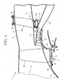
- FIG. 1 to FIG. 3 illustrate one embodiment of a coupling part structure for a vane according to the present invention, and a coupling part of each guide vane as a stator vane constituting a jet engine is described as an example in this embodiment.
- an annular core flow passage 4 is formed on a shaft core side of an engine inner cylinder 3 of an engine main body 2, and a bypass flow passage 6 is formed between the inner circumferential surface of a fan case 5 and the outer circumferential surface of the engine inner cylinder 3 corresponding to an outer portion of the engine main body 2.
- a fan disc 7 is rotatably set around the engine shaft core (not illustrated) with the intermediation of a bearing 8.
- the fan disc 7 is integrally coupled to a turbine rotor of a low-pressure turbine (not illustrated) placed in a back portion (on the right side of FIG. 1 ) of the jet engine 1.
- a plurality of rotor blades 10 are placed at regular intervals in the circumferential direction with the intermediation of fitting grooves 7a, and spacers 11, 11 are respectively placed in a front portion and a back portion between each rotor blade 10 and each fitting groove 7a.
- Annular retainers 12, 13 that support the rotor blades 10 are respectively integrally set in the circumferential direction in a front portion and a back portion of the fan disc 7.
- the retainer 12 in the front portion is integrally coupled to a nose cone 14, and the retainer 13 in the back portion is coaxially and integrally coupled to a rotor 16 of a low-pressure compressor 15 that is adjacently placed downstream of the fan disc 7.
- tip shrouds for vibration prevention and aerodynamic performance improvement are respectively coupled between the tips of the plurality of rotor blades 10, and the tip shrouds are not illustrated in FIG. 1 .
- the jet engine 1 includes a plurality of guide vanes (stator vanes) 20 on the bypass flow passage 6.
- the plurality of guide vanes 20 are placed at regular intervals around the engine inner cylinder 3, and regulate a swirling flow of air flowing in the bypass flow passage 6.
- a composite material of: thermosetting resin (such as epoxy resin, phenolic resin, and polyimide resin) or thermoplastic resin (such as polyetherimide, polyether ether ketone, and polyphenylene sulfide); and reinforcement fiber (such as carbon fiber, aramid fiber, and glass fiber) is used as the constituent material of each guide vane 20.
- the guide vane 20 is formed by, for example, laminating the constituent material in the vane thickness direction or three-dimensionally inweaving the constituent material.
- a vane proximal end portion (vane end portion) 21 on a shaft core side of each guide vane 20 is coupled to an attachment flange 31f of a fan frame 31 placed on the engine inner cylinder 3, and a vane distal end portion (vane end portion) 22 on a side farther from the shaft core of the guide vane 20 is coupled to an attachment flange 5f placed on the fan case 5.
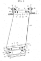
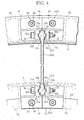
- a coupling support member 33 including a pair of divided pieces 34, 34 separated from each other is placed in a coupling part between the vane proximal end portion 21 of the guide vane 20 and the attachment flange 31f, namely, a vane coupling part, and the pair of divided pieces 34, 34 are joined to the vane proximal end portion 21 of the guide vane 20 from both the sides in the vane thickness direction (the left-right direction in FIG. 2 ).
- Each of the divided pieces 34, 34 of the coupling support member 33 is made of metal such as an aluminum alloy and a titanium alloy, and is attached to the attachment flange 31f using a bolt 38 and a nut 39.
- Opposed walls 35 facing each other are respectively formed on the pair of divided pieces 34, 34 of the coupling support member 33, and the opposed walls 35, 35 are joined to the vane proximal end portion 21 of the guide vane 20 from both the sides in the vane thickness direction.
- one linear protrusion 21b trapezoidal in cross-section is formed on a joint surface 21a on the left side of FIG. 2 , of the joint surfaces 21a, 21a of the vane proximal end portion 21 of the guide vane 20.
- a groove 35b engaged with the linear protrusion 21b formed in the vane proximal end portion 21 of the guide vane 20 is formed on the divided piece 34 similarly on the left side of FIG. 2 , of the two divided pieces 34, 34 constituting the coupling support member 33, namely, an end joint surface 35a of the opposed wall 35 of the divided piece 34 on the left side of FIG. 2 .
- the vane proximal end portion 21 of the guide vane 20 is held between the respective opposed walls 35, 35 of the pair of divided pieces 34, 34 by the fastening force that is applied by a bolt 36 and a nut 37 to the pair of divided pieces 34, 34 of the coupling support member 33 from both the sides in the vane thickness direction.
- an adhesive is interposed between the respective opposed walls 35, 35 of the pair of divided pieces 34, 34 of the coupling support member 33 and the vane proximal end portion 21 of the guide vane 20 held between the opposed walls 35, 35.
- a coupling support member 53 including a pair of divided pieces 54, 54 separated from each other is placed also in a coupling part between the vane distal end portion 22 of the guide vane 20 and the attachment flange 5f, namely, a vane coupling part, and the pair of divided pieces 54, 54 are joined to the vane distal end portion 22 of the guide vane 20 from both the sides in the vane thickness direction (the left-right direction in FIG. 2 ).
- Each of the divided pieces 54, 54 of the coupling support member 53 is made of metal such as an aluminum alloy and a titanium alloy, and is attached to the attachment flange 5f using the bolt 38 and the nut 39.
- Opposed walls 55 facing each other are respectively formed also on the pair of divided pieces 54, 54 of the coupling support member 53, and the opposed walls 55, 55 are joined to the vane distal end portion 22 of the guide vane 20 from both the sides in the vane thickness direction.
- one linear protrusion 22b trapezoidal in cross-section is formed on a joint surface 22a on the left side of FIG. 2 , of the joint surfaces 22a, 22a of the vane distal end portion 22 of the guide vane 20.
- a groove 55b engaged with the linear protrusion 22b formed in the vane distal end portion 22 of the guide vane 20 is formed on the divided piece 54 similarly on the left side of FIG. 2 , of the two divided pieces 54, 54 constituting the coupling support member 53, namely, an end joint surface 55a of the opposed wall 55 of the divided piece 54 on the left side of FIG. 2 .
- the vane distal end portion 22 of the guide vane 20 is held between the respective opposed walls 55, 55 of the pair of divided pieces 54, 54 by the fastening force that is applied by a bolt 56 and a nut 57 to the pair of divided pieces 54, 54 of the coupling support member 53 from both the sides in the vane thickness direction.
- an adhesive is interposed between the respective opposed walls 55, 55 of the pair of divided pieces 54, 54 of the coupling support member 53 and the vane distal end portion 22 of the guide vane 20 held between the opposed walls 55, 55.
- the vane proximal end portion 21 of each guide vane 20 made of the composite material is located between the respective opposed walls 35, 35 of the pair of divided pieces 34, 34 of the coupling support member 33 made of the metal. Further, the linear protrusion 21b formed on the joint surface 21a on the left side of FIG. 2 of the vane proximal end portion 21 is engaged with the groove 35b formed on the joint surface 35a on the left side of FIG. 2 of the coupling support member 33.
- each guide vane 20 is located between the respective opposed walls 55, 55 of the pair of divided pieces 54, 54 of the coupling support member 53 made of the metal. Further, the linear protrusion 22b formed on the joint surface 22a on the left side of FIG. 2 of the vane distal end portion 22 is engaged with the groove 55b formed on the joint surface 55a on the left side of FIG. 2 of the coupling support member 53. In this state, the fastening force obtained by the bolts 56 and the nuts 57 is applied to the pair of divided pieces 54, 54 of the coupling support member 53 from both the sides in the vane thickness direction, whereby the vane distal end portion 22 is held between the respective opposed walls 55, 55 of the pair of divided pieces 54, 54.
- the coupling part structure for the vane according to this embodiment is capable of obtaining a high structural strength while contributing to a reduction in weight of the jet engine 1.
- the coupling strength is a mechanical coupling strength, process management for the coupling part is facilitated compared with the coupling strength in the case of using only an adhesive.
- vane proximal end portion 21 (vane distal end portion 22) is sandwiched between the respective opposed walls 35, 35 (55, 55) of the pair of divided pieces 34, 34 (54, 54) from both the sides in the vane thickness direction, a turn of the vane proximal end portion 21 (vane distal end portion 22) can be avoided compared with, for example, the case where the vane proximal end portion 21 (vane distal end portion 22) is supported by a wall on one side. As a result, a strong coupling state can be maintained.
- the linear protrusion 21b (22b) of the vane proximal end portion 21 (vane distal end portion 22) is engaged with the groove 35b (55b) of the coupling support member 33 (53), whereby the two components are positioned with each other. Accordingly, this assembling work is facilitated.
- the adhesive is interposed between the respective opposed walls 35, 35 (55, 55) of the pair of divided pieces 34, 34 (54, 54) of the coupling support member 33 (53) and the vane proximal end portion 21 (vane distal end portion 22) of the guide vane 20 held between the opposed walls 35, 35 (55, 55), and hence a higher structural strength can be obtained.
- the jet engine according to this embodiment adopts the above-mentioned coupling part structure for the vane, and thus achieves both a reduction in weight and an increase in strength.
- FIG. 4 illustrates another embodiment of the coupling part structure for the vane according to the present invention.
- a coupling part structure for a vane of this embodiment is different from that of the above-mentioned embodiment in that: the linear protrusions 21b (22b) are respectively formed on both the joint surfaces 21a, 21a (22a, 22a) of a vane proximal end portion 21A (vane distal end portion 22A) of each guide vane 20A; and the grooves 35b (55b) that are respectively engaged with the linear protrusions 21b (22b) formed in the vane proximal end portion 21A (vane distal end portion 22A) of the guide vane 20A are respectively formed on both the joint surfaces 35a, 35a (55a, 55a) of the pair of divided pieces 34, 34 (54, 54) of a coupling support member 33A (53A).
- the coupling part structure for the vane of this embodiment is the same as that of the above-mentioned embodiment in the other configurations
- the coupling part structure for the vane according to this embodiment is capable of obtaining a higher structural strength while contributing to the reduction in weight of the jet engine 1.
- the coupling part structure for the vane according to the present invention is applied to the vane coupling part of each guide vane as the stator vane of the jet engine, but the present invention is not limited thereto.
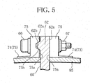
- the coupling part structure for the vane according to the present invention can also be applied to a coupling part between: a tip (distal end portion) 62 of each rotor blade 60 of the jet engine; and a tip shroud 85 that is provided to the tip 62 for the purpose of vibration prevention and aerodynamic performance improvement and rotates together with the rotor blade 60.
- a linear protrusion 62b is formed on a joint surface 62a on the left side of FIG. 5 , of the joint surfaces 62a, 62a of the distal end portion 62 of the rotor blade 60.
- a groove 75b engaged with the linear protrusion 62b formed in the distal end portion 62 of the rotor blade 60 is formed on a joint surface 75a on the left side of FIG. 5 , of the respective joint surfaces 75a, 75a of a pair of divided pieces 74, 74 of a coupling support member 73.
- the coupling part structure for the vane according to the above-mentioned embodiment is also capable of obtaining a higher structural strength while contributing to the reduction in weight of the jet engine.
- the linear protrusion 21b (22b) is formed in the vane proximal end portion 21, 21A (vane distal end portion 22, 22A) of each guide vane 20, 20A, and the groove 35b (55b) is formed in the coupling support member 33, 33A (53, 53A), but the present invention is not limited to this configuration.
- a groove may be formed in the vane proximal end portion 21, 21A (vane distal end portion 22, 22A) of the guide vane 20, 20A, and a linear protrusion may be formed in the coupling support member 33, 33A (53, 53A).
- the number of the linear protrusions 21b (22b) or grooves in the vane proximal end portion 21, 21A (vane distal end portion 22, 22A) of the guide vane 20, 20A is not limited to one, regardless of whether the linear protrusions or grooves are provided on only one of the joint surfaces or on both of one joint surface and another joint surface.
- two linear protrusions or grooves may be provided on both of one joint surface and another joint surface.
- one linear protrusion or groove may be provided on one joint surface, and two linear protrusions or grooves may be provided on another joint surface.
- the linear protrusion 62b is formed in the distal end portion 62 of each rotor blade 60, and the groove 75b is formed in the coupling support member 73, but the present invention is not limited to this configuration.
- a groove may be formed in the distal end portion 62 of the rotor blade 60, and a linear protrusion may be formed in the coupling support member 73.
- the number of the linear protrusions 62b or grooves in the distal end portion 62 of the rotor blade 60 is not limited to one, regardless of whether the linear protrusions or grooves are provided on only one of the joint surfaces or on both of one joint surface and another joint surface.
- two linear protrusions or grooves may be provided on both of one joint surface and another joint surface.
- one linear protrusion or groove may be provided on one joint surface, and two linear protrusions or grooves may be provided on another joint surface.
- linear protrusion 21b, 22b, 62b or the groove 35b, 55b, 75b can be trapezoidal, semicircular, triangular, and rectangular in cross-section, but is not limited to these shapes.
Description
- The present invention relates to, for example, a coupling structure for an engine main body, of guide vanes that are vanes constituting an aircraft jet engine, and a jet engine including the coupling structure for the jet engine.
- Such a jet engine as described above is normally provided with: rotor blades for introducing air into an engine main body; and guide vanes that are stator vanes for controlling a flow of the air introduced by the rotor blades.
- The guide vanes may be required to have only the flow controlling function, and may be required to also have a structural function of coupling a fan frame and a fan case constituting the engine main body, in addition to the flow controlling function.
- In the former case where the guide vanes are required to have only the flow controlling function, a metal material such as an aluminum alloy or a composite material of thermosetting resin such as epoxy resin and reinforcement fiber such as carbon fiber is normally adopted as the constituent material of each guide vane, and a strut that is placed downstream of the guide vanes and is made of a metal material such as an aluminum alloy as its constituent material is provided with the structural function. Meanwhile, in the case where the guide vanes are required to also have the structural function in addition to the flow controlling function, a metal material such as an aluminum alloy is adopted as the constituent material of each guide vane.
- Such guide vanes as described above and a jet engine including the guide vanes are described in, for example,
Patent Documents 1 to 3. Further, in PatenDocument 4 an intermediate casing for a turbojet engine is disclosed which comprises a fin whose end is in the form of tongues adapted to be integrated with inner and outer shells. The shells are arranged opposite to the fin end based on a dovetail type fastener. In Patent Document 5 a flange assembly for a turbine engine is described with a first and a second casing section. The first casing section is positioned radially outward from the turbine engine and comprises a first flange. The second casing section includes a second flange adjacent to the first casing section such that a mating surface of the second flange is positioned flush against a first flange mating surface. -
- Patent Document 1:
U.S. Patent No. 5320490 - Patent Document 2: Japanese Patent No.
2766423 - Patent Document 3: Japanese Patent Laid-Open No.
05-149148 - Patent Document 4: Patent Application No.
FR 2958680 A1 - Patent Document 5: Patent Application No.
EP 1777377 A2 - Here, in response to a demand of recent years for a higher bypass ratio for the purpose of enhancing the fuel efficiency of an aircraft jet engine, the engine diameter tends to be made larger. Along with this, the weight of the aircraft jet engine needs to be urgently reduced.
- For example, in the case where the guide vanes are provided with only the flow controlling function, the weight of each guide vane itself can be reduced by an amount corresponding to using the composite material as its constituent material, whereas the reduction in weight of the aircraft jet engine is prevented by an amount corresponding to assigning the structural function to the strut that is made of the metal material such as the aluminum alloy as its constituent material.
- On the other hand, in the case where the guide vanes are provided with the structural function in addition to the flow controlling function, the metal material such as the aluminum alloy is used as the constituent material of each guide vane, and hence the reduction in weight of the aircraft jet engine is prevented, which is the same problem as that in the case of using the strut. This is a conventional problem to be solved.
- The present invention, which has been made in view of the above-mentioned conventional problem, has an object to provide a coupling structure for a jet engine capable of obtaining a high structural strength while contributing to a reduction in weight of a jet engine, and a jet engine including the coupling structure for the jet engine.
- In order to achieve the above object, the present invention provides a coupling structure for a jet engine comprising a vane made of a composite material of thermosetting resin or thermoplastic resin and reinforcement fiber, and a coupling support member. The coupling support member is made of metal and includes a pair of divided pieces separated from each other, the pair of divided pieces being joined to an end portion of the vane from a first and a second side in a vane thickness direction and each of the pair of divided pieces is attached to an attachment flange of the jet engine. On at least one of the first side and the second side, a joint surface of the end portion of the vane and a joint surface of the divided piece are formed as follows: according to a version (a) the joint surface of the end portion of the vane has at least one linear protrusion and the joint surface of the divided piece has at least one groove being engaged with the linear protrusion. Or according to version (b) the joint surface of the end portion of the vane has at least one groove and the joint surface of the divided piece has at least one linear protrusion being engaged with the groove. The end portion of the vane is held between the pair of divided pieces of the coupling support member, by fastening force (for example, fastening force obtained by bolts and nuts) that is applied to the pair of divided pieces of the coupling support member from both the sides in the vane thickness direction.
- Preferably, an adhesive is interposed between the pair of divided pieces of the coupling support member and the end portion of the vane held between the pair of divided pieces.
- The present invention further provides a jet engine including the above-mentioned coupling structure for the jet engine.
- Here, the coupling structure for the jet engine according to the present invention can be applied to: a coupling part between a vane distal end portion of a guide vane that is a stator vane of a jet engine and an engine main body; and a coupling part between a vane proximal end portion of, similarly, the guide vane and the engine main body, and can also be applied to: a coupling part between a tip (distal end portion) of a rotor blade of the jet engine and a tip shroud; and a coupling part between a hub (proximal end portion) of, similarly, the rotor blade and a shaft. Note that the tip shroud is provided to the tip of the rotor blade for the purpose of vibration prevention and aerodynamic performance improvement, and rotates together with the rotor blade.
- In the coupling structure for the jet engine according to the present invention, the number of the linear protrusions or grooves formed on the joint surface(s) of the end portion of the vane to the coupling support member (the number of the grooves or linear protrusions formed on the end joint surface(s) of the coupling support member) is not limited to one, regardless of whether the linear protrusions or grooves are provided on only one of the joint surfaces or on both of one joint surface and another joint surface. For example, two linear protrusions or grooves may be provided on both of one joint surface and another joint surface. Alternatively, one linear protrusion or groove may be provided on one joint surface, and two linear protrusions or grooves may be provided on another joint surface.
- Further, in the coupling structure for the jet engine according to the present invention, the linear protrusions or grooves formed on the joint surface(s) of the end portion of the vane to the coupling support member (the grooves or linear protrusions formed on the end joint surface(s) of the coupling support member) can be trapezoidal, semicircular, triangular, and rectangular in cross-section, but are not limited to these shapes.
- Moreover, in the coupling structure for the jet engine according to the present invention, examples of the thermosetting resin usable to form the vane include epoxy resin, phenolic resin, and polyimide resin, and examples of the thermoplastic resin usable to form, similarly, the vane include polyetherimide, polyether ether ketone, and polyphenylene sulfide. Then, examples of the reinforcement fiber usable to form the vane include carbon fiber, aramid fiber, and glass fiber. The vane is formed by, for example, laminating the composite material of these substances in the vane thickness direction or three-dimensionally inweaving the composite material thereof. Meanwhile, metal such as an aluminum alloy and a titanium alloy can be used to form the coupling support member.
- In the coupling structure for the jet engine according to the present invention, first, the end portion of the vane made of the composite material is located between respective opposed walls of the pair of divided pieces of the coupling support member made of the metal. Further, the linear protrusion or groove formed on at least any one of the joint surfaces of the end portion of the vane to the coupling support member is engaged with the groove or linear protrusion formed on at least any one of the end joint surfaces of the coupling support member. In this state, for example, the fastening force obtained by the bolts and the nuts is applied to the pair of divided pieces of the coupling support member from both the sides in the vane thickness direction, whereby the end portion of the vane is held between the pair of divided pieces of the coupling support member.
- Accordingly, the coupling structure for the jet engine according to the present invention is capable of obtaining a high structural strength while contributing to a reduction in weight of the jet engine. In addition, because the coupling strength is a mechanical coupling strength, process management for the coupling part is facilitated compared with the coupling strength in the case of using only an adhesive.
- Further, because the end portion of the vane is sandwiched between the pair of divided pieces from both the sides in the vane thickness direction, a turn of the end portion of the vane can be avoided compared with, for example, the case where the end portion of the vane is supported by only one of the divided pieces. As a result, a strong coupling state can be maintained.
- Moreover, at the time of assembling of the end portion of the vane and the coupling support member, the linear protrusion or groove in the end portion of the vane is engaged with the groove or linear protrusion in the coupling support member, whereby the two components are positioned with each other. Accordingly, this assembling work is facilitated.
- Still further, in the coupling structure for the jet engine according to the present invention, if the adhesive is interposed between the pair of divided pieces of the coupling support member and the end portion of the vane held between the pair of divided pieces, a higher structural strength can be obtained.
- Meanwhile, the jet engine according to the present invention adopts the coupling structure for the jet engine according to the present invention, to thereby achieve both a reduction in weight and an increase in strength.
- A coupling structure for a jet engine according to the present invention produces an excellent effect of obtaining a high structural strength while contributing to a reduction in weight of a jet engine.
-
-
FIG. 1 is an explanatory partial cross-sectional view of a front upper portion of a jet engine to which a coupling part structure for a vane according to one embodiment of the present invention is applied. -
FIG. 2 is an explanatory cross-sectional view of a vane coupling part,FIG. 2 illustrating in detail the coupling part structure for the vane inFIG. 1 , the jet engine being observed on its front side. -
FIG. 3 is an explanatory side view of the vane coupling part,FIG. 3 illustrating in detail the coupling part structure for the vane inFIG. 1 . -
FIG. 4 is an explanatory cross-sectional view illustrating in detail a coupling part structure for a vane according to another embodiment of the present invention,FIG. 4 corresponding toFIG. 2 . -
FIG. 5 is an explanatory partial cross-sectional view of a coupling part between a tip of a rotor blade and a tip shroud,FIG. 5 illustrating in detail a coupling part structure for a vane according to still another embodiment of the present invention. - Hereinafter, the present invention is described with reference to the drawings.
-
FIG. 1 to FIG. 3 illustrate one embodiment of a coupling part structure for a vane according to the present invention, and a coupling part of each guide vane as a stator vane constituting a jet engine is described as an example in this embodiment. - As illustrated in
FIG. 1 , in ajet engine 1, an annularcore flow passage 4 is formed on a shaft core side of an engineinner cylinder 3 of an enginemain body 2, and abypass flow passage 6 is formed between the inner circumferential surface of afan case 5 and the outer circumferential surface of the engineinner cylinder 3 corresponding to an outer portion of the enginemain body 2. - In a front portion (on the left side of
FIG. 1 ) of thejet engine 1, afan disc 7 is rotatably set around the engine shaft core (not illustrated) with the intermediation of abearing 8. Thefan disc 7 is integrally coupled to a turbine rotor of a low-pressure turbine (not illustrated) placed in a back portion (on the right side ofFIG. 1 ) of thejet engine 1. - Further, on the outer circumferential surface of the
fan disc 7, a plurality ofrotor blades 10 are placed at regular intervals in the circumferential direction with the intermediation offitting grooves 7a, andspacers rotor blade 10 and eachfitting groove 7a.Annular retainers rotor blades 10 are respectively integrally set in the circumferential direction in a front portion and a back portion of thefan disc 7. Theretainer 12 in the front portion is integrally coupled to anose cone 14, and theretainer 13 in the back portion is coaxially and integrally coupled to arotor 16 of a low-pressure compressor 15 that is adjacently placed downstream of thefan disc 7. - Note that tip shrouds for vibration prevention and aerodynamic performance improvement are respectively coupled between the tips of the plurality of
rotor blades 10, and the tip shrouds are not illustrated inFIG. 1 . - That is, when the
jet engine 1 is operated, the plurality ofrotor blades 10 are rotated together with thefan disc 7, whereby air can be introduced into thecore flow passage 4 and thebypass flow passage 6. - The
jet engine 1 includes a plurality of guide vanes (stator vanes) 20 on thebypass flow passage 6. The plurality ofguide vanes 20 are placed at regular intervals around the engineinner cylinder 3, and regulate a swirling flow of air flowing in thebypass flow passage 6. A composite material of: thermosetting resin (such as epoxy resin, phenolic resin, and polyimide resin) or thermoplastic resin (such as polyetherimide, polyether ether ketone, and polyphenylene sulfide); and reinforcement fiber (such as carbon fiber, aramid fiber, and glass fiber) is used as the constituent material of eachguide vane 20. Theguide vane 20 is formed by, for example, laminating the constituent material in the vane thickness direction or three-dimensionally inweaving the constituent material. - A vane proximal end portion (vane end portion) 21 on a shaft core side of each
guide vane 20 is coupled to anattachment flange 31f of afan frame 31 placed on the engineinner cylinder 3, and a vane distal end portion (vane end portion) 22 on a side farther from the shaft core of theguide vane 20 is coupled to anattachment flange 5f placed on thefan case 5. - In this case, as illustrated in
FIG. 2 andFIG. 3 , acoupling support member 33 including a pair of dividedpieces proximal end portion 21 of theguide vane 20 and theattachment flange 31f, namely, a vane coupling part, and the pair of dividedpieces proximal end portion 21 of theguide vane 20 from both the sides in the vane thickness direction (the left-right direction inFIG. 2 ). Each of the dividedpieces coupling support member 33 is made of metal such as an aluminum alloy and a titanium alloy, and is attached to theattachment flange 31f using abolt 38 and anut 39. -
Opposed walls 35 facing each other are respectively formed on the pair of dividedpieces coupling support member 33, and theopposed walls proximal end portion 21 of theguide vane 20 from both the sides in the vane thickness direction. - In this embodiment, one
linear protrusion 21b trapezoidal in cross-section is formed on ajoint surface 21a on the left side ofFIG. 2 , of thejoint surfaces proximal end portion 21 of theguide vane 20. Meanwhile, agroove 35b engaged with thelinear protrusion 21b formed in the vaneproximal end portion 21 of theguide vane 20 is formed on the dividedpiece 34 similarly on the left side ofFIG. 2 , of the two dividedpieces coupling support member 33, namely, an endjoint surface 35a of theopposed wall 35 of the dividedpiece 34 on the left side ofFIG. 2 . - Then, in this embodiment, the vane
proximal end portion 21 of theguide vane 20 is held between the respective opposedwalls pieces bolt 36 and anut 37 to the pair of dividedpieces coupling support member 33 from both the sides in the vane thickness direction. - Further, in this embodiment, an adhesive is interposed between the respective opposed
walls pieces coupling support member 33 and the vaneproximal end portion 21 of theguide vane 20 held between theopposed walls - Meanwhile, a
coupling support member 53 including a pair of dividedpieces distal end portion 22 of theguide vane 20 and theattachment flange 5f, namely, a vane coupling part, and the pair of dividedpieces distal end portion 22 of theguide vane 20 from both the sides in the vane thickness direction (the left-right direction inFIG. 2 ). Each of the dividedpieces coupling support member 53 is made of metal such as an aluminum alloy and a titanium alloy, and is attached to theattachment flange 5f using thebolt 38 and thenut 39. -
Opposed walls 55 facing each other are respectively formed also on the pair of dividedpieces coupling support member 53, and theopposed walls distal end portion 22 of theguide vane 20 from both the sides in the vane thickness direction. - Also in this vane coupling part, one
linear protrusion 22b trapezoidal in cross-section is formed on ajoint surface 22a on the left side ofFIG. 2 , of thejoint surfaces distal end portion 22 of theguide vane 20. Meanwhile, agroove 55b engaged with thelinear protrusion 22b formed in the vanedistal end portion 22 of theguide vane 20 is formed on the dividedpiece 54 similarly on the left side ofFIG. 2 , of the two dividedpieces coupling support member 53, namely, an endjoint surface 55a of theopposed wall 55 of the dividedpiece 54 on the left side ofFIG. 2 . - Then, the vane
distal end portion 22 of theguide vane 20 is held between the respective opposedwalls pieces bolt 56 and anut 57 to the pair of dividedpieces coupling support member 53 from both the sides in the vane thickness direction. - Further, also in this vane coupling part, an adhesive is interposed between the respective opposed
walls pieces coupling support member 53 and the vanedistal end portion 22 of theguide vane 20 held between theopposed walls - As described above, in the coupling part structure for the vane according to this embodiment, first, the vane
proximal end portion 21 of eachguide vane 20 made of the composite material is located between the respective opposedwalls pieces coupling support member 33 made of the metal. Further, thelinear protrusion 21b formed on thejoint surface 21a on the left side ofFIG. 2 of the vaneproximal end portion 21 is engaged with thegroove 35b formed on thejoint surface 35a on the left side ofFIG. 2 of thecoupling support member 33. In this state, the fastening force obtained by thebolts 36 and the nuts 37 is applied to the pair of dividedpieces coupling support member 33 from both the sides in the vane thickness direction, whereby the vaneproximal end portion 21 is held between the respective opposedwalls pieces - Similarly, the vane
distal end portion 22 of eachguide vane 20 is located between the respective opposedwalls pieces coupling support member 53 made of the metal. Further, thelinear protrusion 22b formed on thejoint surface 22a on the left side ofFIG. 2 of the vanedistal end portion 22 is engaged with thegroove 55b formed on thejoint surface 55a on the left side ofFIG. 2 of thecoupling support member 53. In this state, the fastening force obtained by thebolts 56 and the nuts 57 is applied to the pair of dividedpieces coupling support member 53 from both the sides in the vane thickness direction, whereby the vanedistal end portion 22 is held between the respective opposedwalls pieces - Accordingly, the coupling part structure for the vane according to this embodiment is capable of obtaining a high structural strength while contributing to a reduction in weight of the
jet engine 1. In addition, because the coupling strength is a mechanical coupling strength, process management for the coupling part is facilitated compared with the coupling strength in the case of using only an adhesive. - Further, because the vane proximal end portion 21 (vane distal end portion 22) is sandwiched between the respective opposed
walls 35, 35 (55, 55) of the pair of dividedpieces 34, 34 (54, 54) from both the sides in the vane thickness direction, a turn of the vane proximal end portion 21 (vane distal end portion 22) can be avoided compared with, for example, the case where the vane proximal end portion 21 (vane distal end portion 22) is supported by a wall on one side. As a result, a strong coupling state can be maintained. - Moreover, at the time of assembling of the vane proximal end portion 21 (vane distal end portion 22) and the coupling support member 33 (53), the
linear protrusion 21b (22b) of the vane proximal end portion 21 (vane distal end portion 22) is engaged with thegroove 35b (55b) of the coupling support member 33 (53), whereby the two components are positioned with each other. Accordingly, this assembling work is facilitated. - Still further, in the coupling part structure for the vane according to this embodiment, the adhesive is interposed between the respective opposed
walls 35, 35 (55, 55) of the pair of dividedpieces 34, 34 (54, 54) of the coupling support member 33 (53) and the vane proximal end portion 21 (vane distal end portion 22) of theguide vane 20 held between theopposed walls 35, 35 (55, 55), and hence a higher structural strength can be obtained. - Then, the jet engine according to this embodiment adopts the above-mentioned coupling part structure for the vane, and thus achieves both a reduction in weight and an increase in strength.
-
FIG. 4 illustrates another embodiment of the coupling part structure for the vane according to the present invention. A coupling part structure for a vane of this embodiment is different from that of the above-mentioned embodiment in that: thelinear protrusions 21b (22b) are respectively formed on both thejoint surfaces proximal end portion 21A (vanedistal end portion 22A) of eachguide vane 20A; and thegrooves 35b (55b) that are respectively engaged with thelinear protrusions 21b (22b) formed in the vaneproximal end portion 21A (vanedistal end portion 22A) of theguide vane 20A are respectively formed on both thejoint surfaces pieces 34, 34 (54, 54) of acoupling support member 33A (53A). The coupling part structure for the vane of this embodiment is the same as that of the above-mentioned embodiment in the other configurations. - Accordingly, the coupling part structure for the vane according to this embodiment is capable of obtaining a higher structural strength while contributing to the reduction in weight of the
jet engine 1. - In the above-mentioned embodiments, description is given of an example case where the coupling part structure for the vane according to the present invention is applied to the vane coupling part of each guide vane as the stator vane of the jet engine, but the present invention is not limited thereto. For example, as illustrated in
FIG. 5 , the coupling part structure for the vane according to the present invention can also be applied to a coupling part between: a tip (distal end portion) 62 of eachrotor blade 60 of the jet engine; and atip shroud 85 that is provided to thetip 62 for the purpose of vibration prevention and aerodynamic performance improvement and rotates together with therotor blade 60. - Namely, in this embodiment, a
linear protrusion 62b is formed on ajoint surface 62a on the left side ofFIG. 5 , of thejoint surfaces distal end portion 62 of therotor blade 60. Meanwhile, agroove 75b engaged with thelinear protrusion 62b formed in thedistal end portion 62 of therotor blade 60 is formed on ajoint surface 75a on the left side ofFIG. 5 , of the respectivejoint surfaces pieces coupling support member 73. - In this way, the coupling part structure for the vane according to the above-mentioned embodiment is also capable of obtaining a higher structural strength while contributing to the reduction in weight of the jet engine.
- In each of the above-mentioned embodiments relating to the vane end portion of each guide vane, the
linear protrusion 21b (22b) is formed in the vaneproximal end portion distal end portion guide vane groove 35b (55b) is formed in thecoupling support member proximal end portion distal end portion guide vane coupling support member - Further, the number of the
linear protrusions 21b (22b) or grooves in the vaneproximal end portion distal end portion guide vane grooves 35b (55b) or linear protrusions in thecoupling support member - Similarly, in the above-mentioned embodiment relating to the distal end portion of each rotor blade, the
linear protrusion 62b is formed in thedistal end portion 62 of eachrotor blade 60, and thegroove 75b is formed in thecoupling support member 73, but the present invention is not limited to this configuration. A groove may be formed in thedistal end portion 62 of therotor blade 60, and a linear protrusion may be formed in thecoupling support member 73. - Then, the number of the
linear protrusions 62b or grooves in thedistal end portion 62 of the rotor blade 60 (the number of thegrooves 75b or linear protrusions in the coupling support member 73) is not limited to one, regardless of whether the linear protrusions or grooves are provided on only one of the joint surfaces or on both of one joint surface and another joint surface. For example, two linear protrusions or grooves may be provided on both of one joint surface and another joint surface. Alternatively, one linear protrusion or groove may be provided on one joint surface, and two linear protrusions or grooves may be provided on another joint surface. - Moreover, the
linear protrusion groove - The configurations of the coupling part structure for the vane and the jet engine according to the present invention are not limited to the above-mentioned embodiments.
-
- 1 jet engine
- 20, 20A guide vane (stator vane)
- 21, 21A vane proximal end portion (vane end portion)
- 21a, 22a, 62a joint surface
- 21b, 22b, 62b linear protrusion
- 22, 22A vane distal end portion (vane end portion)
- 33, 33A, 53, 53A, 73 coupling support member
- 34, 54, 74 pair of divided pieces
- 35a, 55a, 75a end joint surface
- 35b, 55b, 75b groove
- 36, 56 bolt
- 37, 57 nut
- 60 rotor blade
- 62 distal end portion (vane end portion)
Claims (2)
- A jet engine (1) comprising a vane (20) made of a composite material of thermosetting resin or thermoplastic resin and reinforcement fiber, and a coupling support member (33, 53), wherein
the coupling support member (33, 53) is made of metal and includes a pair of divided pieces (34, 54) separated from each other, the pair of divided pieces (34, 54) being joined to an end portion (21, 22) of the vane (20) from a first side and a second side in a vane thickness direction and each of the pair of divided pieces (34, 54) is attached to an attachment flange (31f, 5f) of the jet engine (1),
on at least one of the first side and the second side, a joint surface (21a, 22a) of the end portion (21, 22) of the vane (20) and a joint surface (35a, 55a) of the divided piece (34, 54) are formed as follows:(a) the joint surface (21a, 22a) of the end portion (21, 22) of the vane (20) has at least one linear protrusion (21b, 22b) and the joint surface (35a, 55a) of the divided piece (34, 54) has at least one groove (35b, 55b) being engaged with the linear protrusion (21b, 22b), or(b) the joint surface (21a, 22a) of the end portion (21, 22) of the vane (20) has at least one groove and the joint surface (35a, 55a) of the divided piece (34, 54) has at least one linear protrusion being engaged with the groove, andthe end portion (21, 22) of the vane (20) is held between the pair of divided pieces (34, 54) of the coupling support member (33, 53), by fastening force that is applied to the pair of divided pieces (34, 54) of the coupling support member (33, 53) from the first and second sides in the vane thickness direction. - The jet engine (1) according to claim 1, wherein an adhesive is interposed between the pair of divided pieces (34, 54) of the coupling support member (33, 53) and the end portion (21, 22) of the vane (20) held between the pair of divided pieces (34, 54).
Applications Claiming Priority (2)
| Application Number | Priority Date | Filing Date | Title |
|---|---|---|---|
| JP2012021256A JP5962887B2 (en) | 2012-02-02 | 2012-02-02 | Wing connection structure and jet engine using the same |
| PCT/JP2013/052320 WO2013115349A1 (en) | 2012-02-02 | 2013-02-01 | Vane coupling part structure and jet engine using same |
Publications (3)
| Publication Number | Publication Date |
|---|---|
| EP2811138A1 EP2811138A1 (en) | 2014-12-10 |
| EP2811138A4 EP2811138A4 (en) | 2015-10-28 |
| EP2811138B1 true EP2811138B1 (en) | 2018-05-09 |
Family
ID=48905377
Family Applications (1)
| Application Number | Title | Priority Date | Filing Date |
|---|---|---|---|
| EP13743758.8A Active EP2811138B1 (en) | 2012-02-02 | 2013-02-01 | Vane coupling part structure and jet engine using same |
Country Status (7)
| Country | Link |
|---|---|
| US (1) | US9963986B2 (en) |
| EP (1) | EP2811138B1 (en) |
| JP (1) | JP5962887B2 (en) |
| CN (1) | CN104093953B (en) |
| CA (1) | CA2863001C (en) |
| RU (1) | RU2597728C2 (en) |
| WO (1) | WO2013115349A1 (en) |
Families Citing this family (13)
| Publication number | Priority date | Publication date | Assignee | Title |
|---|---|---|---|---|
| FR2958980B1 (en) * | 2010-04-14 | 2013-03-15 | Snecma | RECTIFIER DEVICE FOR TURBOMACHINE |
| JP2015135061A (en) * | 2014-01-16 | 2015-07-27 | 株式会社Ihi | Blade connection part structure and jet engine using the same |
| GB201414587D0 (en) * | 2014-08-18 | 2014-10-01 | Rolls Royce Plc | Mounting Arrangement For Aerofoil Body |
| EP3144499A4 (en) * | 2014-08-22 | 2018-01-24 | IHI Corporation | Cylindrical case |
| DE102015205424A1 (en) | 2015-03-25 | 2016-09-29 | Ebm-Papst Mulfingen Gmbh & Co. Kg | vane |
| FR3036435B1 (en) | 2015-05-22 | 2020-01-24 | Safran Ceramics | TURBINE RING ASSEMBLY |
| US10443449B2 (en) * | 2015-07-24 | 2019-10-15 | Pratt & Whitney Canada Corp. | Spoke mounting arrangement |
| US10247035B2 (en) * | 2015-07-24 | 2019-04-02 | Pratt & Whitney Canada Corp. | Spoke locking architecture |
| CA2936180A1 (en) | 2015-07-24 | 2017-01-24 | Pratt & Whitney Canada Corp. | Multiple spoke cooling system and method |
| FR3045099B1 (en) * | 2015-12-14 | 2018-01-26 | Safran Aircraft Engines | SPACER FOR ASSEMBLING A BLADE ON A HUB OF A TURBOMACHINE |
| FR3088367B1 (en) * | 2018-11-09 | 2020-11-20 | Safran Aircraft Engines | FLOW RECTIFIER ASSEMBLY |
| US11065825B2 (en) * | 2018-12-05 | 2021-07-20 | Raytheon Technologies Corporation | High temperature composite seal |
| CN111561480B (en) * | 2020-05-14 | 2022-02-22 | 中国航发沈阳发动机研究所 | Stator structure |
Family Cites Families (17)
| Publication number | Priority date | Publication date | Assignee | Title |
|---|---|---|---|---|
| US4249859A (en) * | 1977-12-27 | 1981-02-10 | United Technologies Corporation | Preloaded engine inlet shroud |
| JPH06105048B2 (en) | 1991-05-28 | 1994-12-21 | ゼネラル・エレクトリック・カンパニイ | A device that attaches the core frame to the vane frame with a stable center ring in a detachable manner. |
| US5222360A (en) * | 1991-10-30 | 1993-06-29 | General Electric Company | Apparatus for removably attaching a core frame to a vane frame with a stable mid ring |
| JP2766423B2 (en) | 1991-05-28 | 1998-06-18 | ゼネラル・エレクトリック・カンパニイ | Removable turbofan engine assembly |
| FR2685383B1 (en) * | 1991-12-18 | 1994-02-11 | Snecma | STRUCTURAL ARM OF THE HOUSING OF A TURBOMACHINE. |
| JP3478984B2 (en) * | 1999-01-18 | 2003-12-15 | 株式会社巴技研 | Structure for fixing columnar objects |
| JP2001020392A (en) * | 1999-07-07 | 2001-01-23 | Shimizu Corp | Joining structure of structural member |
| DE60307302T2 (en) * | 2003-12-18 | 2007-07-19 | Techspace Aero S.A. | Fastening device for stator blade, and Leitschaufelstufe a compressor with such a device |
| RU40655U1 (en) * | 2004-04-05 | 2004-09-20 | Открытое акционерное общество "Научно-производственное объединение "Сатурн" | ENGINE RACK ASSEMBLY |
| US8079773B2 (en) * | 2005-10-18 | 2011-12-20 | General Electric Company | Methods and apparatus for assembling composite structures |
| FR2906296A1 (en) * | 2006-09-26 | 2008-03-28 | Snecma Sa | DEVICE FOR FASTENING A FIXED BLADE IN AN ANNULAR CASE FOR TURBOMACHINE, TURBOREACTOR INCORPORATING THE DEVICE AND METHOD FOR MOUNTING THE BLADE. |
| GB2447964B (en) * | 2007-03-29 | 2012-07-18 | Gurit Uk Ltd | Moulding material |
| SE0700823L (en) * | 2007-03-30 | 2008-10-01 | Volvo Aero Corp | Component for a gas turbine engine, a jet engine equipped with such a component, and an airplane equipped with such a jet engine |
| JP5321186B2 (en) * | 2009-03-26 | 2013-10-23 | 株式会社Ihi | CMC turbine stationary blade |
| US9228446B2 (en) * | 2009-10-27 | 2016-01-05 | Gkn Aerospace Sweden Ab | Gas turbine engine component |
| FR2958680B1 (en) * | 2010-04-13 | 2015-08-14 | Snecma | INTERMEDIATE CASE OF MULTI-FLOW TURBOREACTOR |
| US8734101B2 (en) * | 2010-08-31 | 2014-05-27 | General Electric Co. | Composite vane mounting |
-
2012
- 2012-02-02 JP JP2012021256A patent/JP5962887B2/en active Active
-
2013
- 2013-02-01 WO PCT/JP2013/052320 patent/WO2013115349A1/en active Application Filing
- 2013-02-01 RU RU2014135547/06A patent/RU2597728C2/en active
- 2013-02-01 EP EP13743758.8A patent/EP2811138B1/en active Active
- 2013-02-01 CN CN201380007665.9A patent/CN104093953B/en not_active Expired - Fee Related
- 2013-02-01 CA CA2863001A patent/CA2863001C/en active Active
- 2013-02-01 US US14/375,556 patent/US9963986B2/en active Active
Non-Patent Citations (1)
| Title |
|---|
| None * |
Also Published As
| Publication number | Publication date |
|---|---|
| JP5962887B2 (en) | 2016-08-03 |
| US20150064000A1 (en) | 2015-03-05 |
| EP2811138A1 (en) | 2014-12-10 |
| CA2863001A1 (en) | 2013-08-08 |
| US9963986B2 (en) | 2018-05-08 |
| JP2013160101A (en) | 2013-08-19 |
| CA2863001C (en) | 2016-08-16 |
| CN104093953A (en) | 2014-10-08 |
| CN104093953B (en) | 2016-11-02 |
| EP2811138A4 (en) | 2015-10-28 |
| RU2597728C2 (en) | 2016-09-20 |
| RU2014135547A (en) | 2016-03-27 |
| WO2013115349A1 (en) | 2013-08-08 |
Similar Documents
| Publication | Publication Date | Title |
|---|---|---|
| EP2811138B1 (en) | Vane coupling part structure and jet engine using same | |
| US9777585B2 (en) | Guide vane assembly | |
| US9482095B2 (en) | Web connected dual aerofoil members | |
| EP1908920A2 (en) | Guide vane and gas turbine comprising a plurality of these guide vanes | |
| EP2713014A2 (en) | Annulus filler for axial flow machine | |
| US20110150643A1 (en) | Architecture of a Compressor Rectifier | |
| CN106286407B (en) | Shaft turbine compressor housing | |
| JP2015528540A (en) | Low radius ratio fan for gas turbine engines | |
| US10215040B2 (en) | Coupling part structure for vane and jet engine including the same | |
| US20140003958A1 (en) | Fairing assembly | |
| US9896963B2 (en) | Coupling part structure for vane and jet engine including the same | |
| CN108868902B (en) | Component with co-bonded composite and metallic ring and method of assembling same | |
| EP3090134B1 (en) | Fan blade with root through holes | |
| US9435215B2 (en) | Gas turbine structure |
Legal Events
| Date | Code | Title | Description |
|---|---|---|---|
| PUAI | Public reference made under article 153(3) epc to a published international application that has entered the european phase |
Free format text: ORIGINAL CODE: 0009012 |
|
| 17P | Request for examination filed |
Effective date: 20140731 |
|
| AK | Designated contracting states |
Kind code of ref document: A1 Designated state(s): AL AT BE BG CH CY CZ DE DK EE ES FI FR GB GR HR HU IE IS IT LI LT LU LV MC MK MT NL NO PL PT RO RS SE SI SK SM TR |
|
| AX | Request for extension of the european patent |
Extension state: BA ME |
|
| DAX | Request for extension of the european patent (deleted) | ||
| RA4 | Supplementary search report drawn up and despatched (corrected) |
Effective date: 20150925 |
|
| RIC1 | Information provided on ipc code assigned before grant |
Ipc: F02C 7/00 20060101ALI20150921BHEP Ipc: F02K 3/06 20060101ALI20150921BHEP Ipc: F01D 25/24 20060101ALI20150921BHEP Ipc: F01D 5/28 20060101ALI20150921BHEP Ipc: F01D 9/02 20060101ALI20150921BHEP Ipc: F04D 29/54 20060101ALI20150921BHEP Ipc: F02C 7/20 20060101AFI20150921BHEP |
|
| STAA | Information on the status of an ep patent application or granted ep patent |
Free format text: STATUS: EXAMINATION IS IN PROGRESS |
|
| 17Q | First examination report despatched |
Effective date: 20161205 |
|
| GRAP | Despatch of communication of intention to grant a patent |
Free format text: ORIGINAL CODE: EPIDOSNIGR1 |
|
| STAA | Information on the status of an ep patent application or granted ep patent |
Free format text: STATUS: GRANT OF PATENT IS INTENDED |
|
| INTG | Intention to grant announced |
Effective date: 20170803 |
|
| GRAJ | Information related to disapproval of communication of intention to grant by the applicant or resumption of examination proceedings by the epo deleted |
Free format text: ORIGINAL CODE: EPIDOSDIGR1 |
|
| STAA | Information on the status of an ep patent application or granted ep patent |
Free format text: STATUS: EXAMINATION IS IN PROGRESS |
|
| GRAP | Despatch of communication of intention to grant a patent |
Free format text: ORIGINAL CODE: EPIDOSNIGR1 |
|
| STAA | Information on the status of an ep patent application or granted ep patent |
Free format text: STATUS: GRANT OF PATENT IS INTENDED |
|
| INTC | Intention to grant announced (deleted) | ||
| INTG | Intention to grant announced |
Effective date: 20171208 |
|
| GRAS | Grant fee paid |
Free format text: ORIGINAL CODE: EPIDOSNIGR3 |
|
| GRAA | (expected) grant |
Free format text: ORIGINAL CODE: 0009210 |
|
| STAA | Information on the status of an ep patent application or granted ep patent |
Free format text: STATUS: THE PATENT HAS BEEN GRANTED |
|
| AK | Designated contracting states |
Kind code of ref document: B1 Designated state(s): AL AT BE BG CH CY CZ DE DK EE ES FI FR GB GR HR HU IE IS IT LI LT LU LV MC MK MT NL NO PL PT RO RS SE SI SK SM TR |
|
| REG | Reference to a national code |
Ref country code: GB Ref legal event code: FG4D |
|
| REG | Reference to a national code |
Ref country code: CH Ref legal event code: EP Ref country code: AT Ref legal event code: REF Ref document number: 997774 Country of ref document: AT Kind code of ref document: T Effective date: 20180515 |
|
| REG | Reference to a national code |
Ref country code: DE Ref legal event code: R096 Ref document number: 602013037234 Country of ref document: DE Ref country code: IE Ref legal event code: FG4D |
|
| REG | Reference to a national code |
Ref country code: DE Ref legal event code: R096 Ref document number: 602013037234 Country of ref document: DE |
|
| REG | Reference to a national code |
Ref country code: NL Ref legal event code: MP Effective date: 20180509 |
|
| REG | Reference to a national code |
Ref country code: LT Ref legal event code: MG4D |
|
| PG25 | Lapsed in a contracting state [announced via postgrant information from national office to epo] |
Ref country code: BG Free format text: LAPSE BECAUSE OF FAILURE TO SUBMIT A TRANSLATION OF THE DESCRIPTION OR TO PAY THE FEE WITHIN THE PRESCRIBED TIME-LIMIT Effective date: 20180809 Ref country code: FI Free format text: LAPSE BECAUSE OF FAILURE TO SUBMIT A TRANSLATION OF THE DESCRIPTION OR TO PAY THE FEE WITHIN THE PRESCRIBED TIME-LIMIT Effective date: 20180509 Ref country code: NO Free format text: LAPSE BECAUSE OF FAILURE TO SUBMIT A TRANSLATION OF THE DESCRIPTION OR TO PAY THE FEE WITHIN THE PRESCRIBED TIME-LIMIT Effective date: 20180809 Ref country code: SE Free format text: LAPSE BECAUSE OF FAILURE TO SUBMIT A TRANSLATION OF THE DESCRIPTION OR TO PAY THE FEE WITHIN THE PRESCRIBED TIME-LIMIT Effective date: 20180509 Ref country code: ES Free format text: LAPSE BECAUSE OF FAILURE TO SUBMIT A TRANSLATION OF THE DESCRIPTION OR TO PAY THE FEE WITHIN THE PRESCRIBED TIME-LIMIT Effective date: 20180509 Ref country code: LT Free format text: LAPSE BECAUSE OF FAILURE TO SUBMIT A TRANSLATION OF THE DESCRIPTION OR TO PAY THE FEE WITHIN THE PRESCRIBED TIME-LIMIT Effective date: 20180509 |
|
| PG25 | Lapsed in a contracting state [announced via postgrant information from national office to epo] |
Ref country code: HR Free format text: LAPSE BECAUSE OF FAILURE TO SUBMIT A TRANSLATION OF THE DESCRIPTION OR TO PAY THE FEE WITHIN THE PRESCRIBED TIME-LIMIT Effective date: 20180509 Ref country code: NL Free format text: LAPSE BECAUSE OF FAILURE TO SUBMIT A TRANSLATION OF THE DESCRIPTION OR TO PAY THE FEE WITHIN THE PRESCRIBED TIME-LIMIT Effective date: 20180509 Ref country code: RS Free format text: LAPSE BECAUSE OF FAILURE TO SUBMIT A TRANSLATION OF THE DESCRIPTION OR TO PAY THE FEE WITHIN THE PRESCRIBED TIME-LIMIT Effective date: 20180509 Ref country code: GR Free format text: LAPSE BECAUSE OF FAILURE TO SUBMIT A TRANSLATION OF THE DESCRIPTION OR TO PAY THE FEE WITHIN THE PRESCRIBED TIME-LIMIT Effective date: 20180810 Ref country code: LV Free format text: LAPSE BECAUSE OF FAILURE TO SUBMIT A TRANSLATION OF THE DESCRIPTION OR TO PAY THE FEE WITHIN THE PRESCRIBED TIME-LIMIT Effective date: 20180509 |
|
| REG | Reference to a national code |
Ref country code: AT Ref legal event code: MK05 Ref document number: 997774 Country of ref document: AT Kind code of ref document: T Effective date: 20180509 |
|
| PG25 | Lapsed in a contracting state [announced via postgrant information from national office to epo] |
Ref country code: EE Free format text: LAPSE BECAUSE OF FAILURE TO SUBMIT A TRANSLATION OF THE DESCRIPTION OR TO PAY THE FEE WITHIN THE PRESCRIBED TIME-LIMIT Effective date: 20180509 Ref country code: SK Free format text: LAPSE BECAUSE OF FAILURE TO SUBMIT A TRANSLATION OF THE DESCRIPTION OR TO PAY THE FEE WITHIN THE PRESCRIBED TIME-LIMIT Effective date: 20180509 Ref country code: AT Free format text: LAPSE BECAUSE OF FAILURE TO SUBMIT A TRANSLATION OF THE DESCRIPTION OR TO PAY THE FEE WITHIN THE PRESCRIBED TIME-LIMIT Effective date: 20180509 Ref country code: DK Free format text: LAPSE BECAUSE OF FAILURE TO SUBMIT A TRANSLATION OF THE DESCRIPTION OR TO PAY THE FEE WITHIN THE PRESCRIBED TIME-LIMIT Effective date: 20180509 Ref country code: RO Free format text: LAPSE BECAUSE OF FAILURE TO SUBMIT A TRANSLATION OF THE DESCRIPTION OR TO PAY THE FEE WITHIN THE PRESCRIBED TIME-LIMIT Effective date: 20180509 Ref country code: CZ Free format text: LAPSE BECAUSE OF FAILURE TO SUBMIT A TRANSLATION OF THE DESCRIPTION OR TO PAY THE FEE WITHIN THE PRESCRIBED TIME-LIMIT Effective date: 20180509 Ref country code: PL Free format text: LAPSE BECAUSE OF FAILURE TO SUBMIT A TRANSLATION OF THE DESCRIPTION OR TO PAY THE FEE WITHIN THE PRESCRIBED TIME-LIMIT Effective date: 20180509 |
|
| REG | Reference to a national code |
Ref country code: DE Ref legal event code: R097 Ref document number: 602013037234 Country of ref document: DE |
|
| PG25 | Lapsed in a contracting state [announced via postgrant information from national office to epo] |
Ref country code: SM Free format text: LAPSE BECAUSE OF FAILURE TO SUBMIT A TRANSLATION OF THE DESCRIPTION OR TO PAY THE FEE WITHIN THE PRESCRIBED TIME-LIMIT Effective date: 20180509 |
|
| PLBE | No opposition filed within time limit |
Free format text: ORIGINAL CODE: 0009261 |
|
| STAA | Information on the status of an ep patent application or granted ep patent |
Free format text: STATUS: NO OPPOSITION FILED WITHIN TIME LIMIT |
|
| 26N | No opposition filed |
Effective date: 20190212 |
|
| PG25 | Lapsed in a contracting state [announced via postgrant information from national office to epo] |
Ref country code: SI Free format text: LAPSE BECAUSE OF FAILURE TO SUBMIT A TRANSLATION OF THE DESCRIPTION OR TO PAY THE FEE WITHIN THE PRESCRIBED TIME-LIMIT Effective date: 20180509 |
|
| REG | Reference to a national code |
Ref country code: CH Ref legal event code: PL |
|
| PG25 | Lapsed in a contracting state [announced via postgrant information from national office to epo] |
Ref country code: LU Free format text: LAPSE BECAUSE OF NON-PAYMENT OF DUE FEES Effective date: 20190201 Ref country code: MC Free format text: LAPSE BECAUSE OF FAILURE TO SUBMIT A TRANSLATION OF THE DESCRIPTION OR TO PAY THE FEE WITHIN THE PRESCRIBED TIME-LIMIT Effective date: 20180509 |
|
| REG | Reference to a national code |
Ref country code: BE Ref legal event code: MM Effective date: 20190228 |
|
| REG | Reference to a national code |
Ref country code: IE Ref legal event code: MM4A |
|
| PG25 | Lapsed in a contracting state [announced via postgrant information from national office to epo] |
Ref country code: AL Free format text: LAPSE BECAUSE OF FAILURE TO SUBMIT A TRANSLATION OF THE DESCRIPTION OR TO PAY THE FEE WITHIN THE PRESCRIBED TIME-LIMIT Effective date: 20180509 |
|
| PG25 | Lapsed in a contracting state [announced via postgrant information from national office to epo] |
Ref country code: LI Free format text: LAPSE BECAUSE OF NON-PAYMENT OF DUE FEES Effective date: 20190228 Ref country code: CH Free format text: LAPSE BECAUSE OF NON-PAYMENT OF DUE FEES Effective date: 20190228 |
|
| PG25 | Lapsed in a contracting state [announced via postgrant information from national office to epo] |
Ref country code: IE Free format text: LAPSE BECAUSE OF NON-PAYMENT OF DUE FEES Effective date: 20190201 |
|
| PG25 | Lapsed in a contracting state [announced via postgrant information from national office to epo] |
Ref country code: BE Free format text: LAPSE BECAUSE OF NON-PAYMENT OF DUE FEES Effective date: 20190228 |
|
| PG25 | Lapsed in a contracting state [announced via postgrant information from national office to epo] |
Ref country code: TR Free format text: LAPSE BECAUSE OF FAILURE TO SUBMIT A TRANSLATION OF THE DESCRIPTION OR TO PAY THE FEE WITHIN THE PRESCRIBED TIME-LIMIT Effective date: 20180509 |
|
| PG25 | Lapsed in a contracting state [announced via postgrant information from national office to epo] |
Ref country code: MT Free format text: LAPSE BECAUSE OF NON-PAYMENT OF DUE FEES Effective date: 20190201 Ref country code: PT Free format text: LAPSE BECAUSE OF FAILURE TO SUBMIT A TRANSLATION OF THE DESCRIPTION OR TO PAY THE FEE WITHIN THE PRESCRIBED TIME-LIMIT Effective date: 20180910 |
|
| PG25 | Lapsed in a contracting state [announced via postgrant information from national office to epo] |
Ref country code: CY Free format text: LAPSE BECAUSE OF FAILURE TO SUBMIT A TRANSLATION OF THE DESCRIPTION OR TO PAY THE FEE WITHIN THE PRESCRIBED TIME-LIMIT Effective date: 20180509 |
|
| PG25 | Lapsed in a contracting state [announced via postgrant information from national office to epo] |
Ref country code: IS Free format text: LAPSE BECAUSE OF FAILURE TO SUBMIT A TRANSLATION OF THE DESCRIPTION OR TO PAY THE FEE WITHIN THE PRESCRIBED TIME-LIMIT Effective date: 20180909 |
|
| PG25 | Lapsed in a contracting state [announced via postgrant information from national office to epo] |
Ref country code: HU Free format text: LAPSE BECAUSE OF FAILURE TO SUBMIT A TRANSLATION OF THE DESCRIPTION OR TO PAY THE FEE WITHIN THE PRESCRIBED TIME-LIMIT; INVALID AB INITIO Effective date: 20130201 |
|
| PGFP | Annual fee paid to national office [announced via postgrant information from national office to epo] |
Ref country code: IT Payment date: 20220119 Year of fee payment: 10 Ref country code: FR Payment date: 20220120 Year of fee payment: 10 |
|
| PG25 | Lapsed in a contracting state [announced via postgrant information from national office to epo] |
Ref country code: MK Free format text: LAPSE BECAUSE OF FAILURE TO SUBMIT A TRANSLATION OF THE DESCRIPTION OR TO PAY THE FEE WITHIN THE PRESCRIBED TIME-LIMIT Effective date: 20180509 |
|
| PGFP | Annual fee paid to national office [announced via postgrant information from national office to epo] |
Ref country code: GB Payment date: 20230120 Year of fee payment: 11 Ref country code: DE Payment date: 20230119 Year of fee payment: 11 |
|
| PG25 | Lapsed in a contracting state [announced via postgrant information from national office to epo] |
Ref country code: IT Free format text: LAPSE BECAUSE OF NON-PAYMENT OF DUE FEES Effective date: 20230201 Ref country code: FR Free format text: LAPSE BECAUSE OF NON-PAYMENT OF DUE FEES Effective date: 20230228 |