EP2811068A1 - Method and arrangement for degassing treatment substance of a fiber web - Google Patents
Method and arrangement for degassing treatment substance of a fiber web Download PDFInfo
- Publication number
- EP2811068A1 EP2811068A1 EP13170730.9A EP13170730A EP2811068A1 EP 2811068 A1 EP2811068 A1 EP 2811068A1 EP 13170730 A EP13170730 A EP 13170730A EP 2811068 A1 EP2811068 A1 EP 2811068A1
- Authority
- EP
- European Patent Office
- Prior art keywords
- treatment substance
- degassing
- temperature
- control unit
- substance
- Prior art date
- Legal status (The legal status is an assumption and is not a legal conclusion. Google has not performed a legal analysis and makes no representation as to the accuracy of the status listed.)
- Granted
Links
Images

Classifications
-
- D—TEXTILES; PAPER
- D21—PAPER-MAKING; PRODUCTION OF CELLULOSE
- D21H—PULP COMPOSITIONS; PREPARATION THEREOF NOT COVERED BY SUBCLASSES D21C OR D21D; IMPREGNATING OR COATING OF PAPER; TREATMENT OF FINISHED PAPER NOT COVERED BY CLASS B31 OR SUBCLASS D21G; PAPER NOT OTHERWISE PROVIDED FOR
- D21H19/00—Coated paper; Coating material
-
- D—TEXTILES; PAPER
- D21—PAPER-MAKING; PRODUCTION OF CELLULOSE
- D21H—PULP COMPOSITIONS; PREPARATION THEREOF NOT COVERED BY SUBCLASSES D21C OR D21D; IMPREGNATING OR COATING OF PAPER; TREATMENT OF FINISHED PAPER NOT COVERED BY CLASS B31 OR SUBCLASS D21G; PAPER NOT OTHERWISE PROVIDED FOR
- D21H21/00—Non-fibrous material added to the pulp, characterised by its function, form or properties; Paper-impregnating or coating material, characterised by its function, form or properties
- D21H21/14—Non-fibrous material added to the pulp, characterised by its function, form or properties; Paper-impregnating or coating material, characterised by its function, form or properties characterised by function or properties in or on the paper
- D21H21/16—Sizing or water-repelling agents
-
- D—TEXTILES; PAPER
- D21—PAPER-MAKING; PRODUCTION OF CELLULOSE
- D21H—PULP COMPOSITIONS; PREPARATION THEREOF NOT COVERED BY SUBCLASSES D21C OR D21D; IMPREGNATING OR COATING OF PAPER; TREATMENT OF FINISHED PAPER NOT COVERED BY CLASS B31 OR SUBCLASS D21G; PAPER NOT OTHERWISE PROVIDED FOR
- D21H23/00—Processes or apparatus for adding material to the pulp or to the paper
- D21H23/02—Processes or apparatus for adding material to the pulp or to the paper characterised by the manner in which substances are added
- D21H23/22—Addition to the formed paper
- D21H23/46—Pouring or allowing the fluid to flow in a continuous stream on to the surface, the entire stream being carried away by the paper
- D21H23/48—Curtain coaters
Definitions
- the invention relates to a method and to an arrangement for degassing treatment substance, especially for degassing a coating color or a sizing agent, of a fiber web. More especially the invention relates to a method according to the preamble of claim 1 and to an arrangement according to the preamble of claim 8.
- a typical production and treatment line comprises a head box, a wire section and a press section as well as a subsequent drying section and a reel-up.
- the production and treatment line can further comprise other devices and sections for finishing the fiber web, for example, a sizer, a calender, a coating section.
- the production and treatment line also comprises at least one winder for forming customer rolls as well as a roll packaging apparatus.
- fiber webs are meant for example paper and board webs.
- Sizing is used to alter the properties of a fiber web by adding sizing agents (sizing medium), for example glue chemicals onto the surface of the fiber web at the fiber web machine.
- sizing agent for example glue chemicals
- coating onto surface of a fiber web is added a layer or layers of coating color (coating medium) at a coating station followed by drying.
- the coating or the sizing of a fiber web typically utilizes a coating device - a coater - or a sizing device - a sizer.
- a coating device - a coater - or a sizing device - a sizer In connection with the coaters and sizers different kinds of application technology for application of the coating medium or the sizing medium on the fiber web are employed, for example curtain technology or blade coating technology or film transfer technology or rod coating technology or air brush coating technology or spray coating technology.
- the mixing of gases, such as air, with the liquids and compounds used in the process typically causes many problems.
- gases such as air
- the gas and gas bubbles in the treatment substance cause unevenness on the surface of the web.
- the seriousness of the problems varies for example due to their different tendency to bind with gases.
- the significance of the problem depends also on the coating or sizing technology used.
- the coating substance is arranged to rise stepwise up the wall of the drum, so that the coating substance will form a thin veil-like film on at least two different step levels, whereupon the gas bubbles in the coating substance will break and discharge.
- the inner surface of the drum is designed to be stepped, comprising at least two step levels so that the coating substance rising upwards due to the effect of the rotating motion will form a thin veil-like film on the said at least two step levels, respectively.
- EP publication 0517223 A1 is disclosed manufacturing of a coated paper to be used for a usual printing and using a curtain type coating method, in which is enabled by de-aerating a coating substance having a high concentration and a high viscosity is de-aerated under a degree of vacuum of a saturated vapor pressure or less and under a condition of applying shear to the coating substance, which is formed as a free-falling curtain in a vertical direction and a printing base paper is coated with the de-aerated coating liquid so that the free-falling curtain of the coating substance collides with the coating base paper running continuously in a direction crossing the free-falling curtain.
- DE 102005017952 is disclosed a method for degassing a coating substance, which substance is passed through a vacuum degassing unit at a temperature close to its boiling point and especially 40-60 °C under a pressure of 20-100 mbar for degassing the treatment substance in temperatures near boiling temperature.
- Heat is supplied by a heat exchanger or heated walls of the vacuum degasser.
- One disadvantage of this known method is that heating of the coating substance increases solubility of gases into the substance liquid and increases amount of steam that must be removed by the vacuum degassing unit from the system and therefore more powerful and bigger unit is needed and the energy consumption is increased.
- heating of the treatment substance might, for example due to chemical reactions initiated by the heat or due to non-tolerance of heat of some components of the treatment substance, deteriorate properties required from treatment substance.
- thermal coatings will lose brightness already at temperatures 50 °C and some latex coatings will suffer instability in temperatures over 45°C in longer run.
- the heating of the treatment substance which typically is already in rather, even too high temperatures, for example 40 - 50 °C, when passed to the degassing, creates more steam into the substance.
- a suction pump of the degassing unit from the treatment substance, which might in some cases be problematic since some suction pump types, for example dry screw vacuum pumps, which are operable in vacuums over 22 mbar, and liquid ring vacuum pumps, which are operable in vacuums over 35 mbar, do not function well when steam is present.
- An object of the invention is to create a method and an arrangement for degassing treatment substance of a fiber web in which the above problems and disadvantages are eliminated or at least minimized.
- Another object of the invention is to provide a method and an arrangement for degassing treatment substance of a fiber web in which high temperatures of the treatment substance are avoided.
- a particular object is to prevent harmful chemical reactions in treatment substance during degassing.
- a further particular object is to provide a method and an arrangement for degassing treatment substance of a fiber web in which the temperature of the treatment substance is controlled during degassing.
- a further particular object is to provide a method and an arrangement for degassing treatment substance of a fiber web in which the suction pump type of the degassing unit choice is not limited by steam tolerance.
- the method for degassing treatment substance of a fiber web according to the invention is mainly characterized by the features of claim 1 and the arrangement for degassing treatment substance of a fiber web according to the invention is mainly characterized by the features of claim 8.
- the treatment substance in particular a coating color or a sizing agent, of a fiber web the treatment substance is degassed in a degassing unit and temperature of the treatment substance is adjusted to temperature below 35 °C by cooling the treatment substance in a temperature control unit before degassing of the treatment substance in the degassing unit.
- the arrangement for degassing treatment substance of a fiber web comprises a degassing unit and a temperature control unit, advantageously a cooler or a heat exchanger, before the degassing unit for adjusting temperature of the treatment substance to temperature below 35 °C before degassing.
- temperature changes of the treatment substance are evened out in the temperature control unit before degassing of the treatment substance in the degassing unit.
- the temperature control unit maintains the temperature changes of the treatments substance slow, for example about 1°C/15 min.
- the treatment substance is cooled to temperatures 20-30 °C before degassing.
- the temperature of the treatment substance in particular the temperature of a coating or a sizing substance, is controlled before degassing the substance in the degassing unit by cooling the substance by a cooler, for example by a heat exchanger.
- the cooler advantageously maintains the temperature changes of the treatments substance as slow as possible by which best environment and best conditions for degassing and for functions of the degassing unit and the vacuum system are provided. Thus improved degassing effect is achieved.
- the temperature of the treatment substance is controlled by a heat exchanger, advantageously by a cooler.
- the arrangement comprises a droplet separator between the degassing unit and the vacuum system.
- the arrangement comprises a dry screw vacuum pump for providing vacuum 20 - 40 mbar in the vacuum system.
- a droplet separator before the dry screw vacuum pump.
- the process of treatment substance flow the treatment substance is delivered to a feed tank 11.
- temperature control unit 12 which is for example a heat exchanger or advantageously a cooler.
- the temperature controlled, advantageously cooled treatment substance is then passed to degassing unit 13, which comprises a vacuum system 14 with a suction pump (not shown) for removing gas from the treatment substance.
- degassing unit 13 which comprises a vacuum system 14 with a suction pump (not shown) for removing gas from the treatment substance.
- the degassed treatment substance is the passed to a working tank 15, from which the treatment substance is passed to a coating device or to a sizing device (not shown).
- the degassed treatment substance may also be passed directly to a coating head / an applicator of a coating device or to a sizing head / an applicator of a sizing device (not shown).
- treatment substance is delivered via feed channel 20 to the temperature control unit 12 from the feed tank 11 ( fig. 1 ). Temperature of the treatment substance is measured by a temperature sensor 12A and pressure of the treatment substance in the feed channel 20 is measured by a pressure sensor 20A. Measurement information from the temperature sensor 12A and the pressure sensor 20A is transmitted to a control unit 25. From the temperature control unit 12 the treatment substance is passed to degassing unit 13, in which the gas is separated from the treatment substance and removed by the vacuum system 14. The gas flow is passed to the vacuum system via a droplet separator 16, in which the steam in the substance is cooled to condensate and moisture is separated from the gas flow.
- Pressure in the degassing unit 13 is measured by a pressure sensor 13A and its measurement information is transmitted to the control unit 25.
- the control unit 25 controls operation of the system and especially controls the pressure created by the vacuum system and temperature conditions of the treatment system by adjusting the operation of the temperature control unit 12.
- From the degassing unit the degassed treatment substance is fed via a feed channel 22 to the working tank 15 ( fig. 1 ).
- the degassed treatment substance may also be passed directly to a coating head / an applicator of a coating device or to a sizing head / an applicator of a sizing device (not shown).
- Temperature control unit 12 is advantageously a cooler or a heat exchanger, which maintains the temperature changes of the treatments substance as slow as possible and thus best environment and best conditions for degassing and for functions of the degassing unit 13 and the vacuum system 14 are provided.
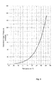
- FIG 3 is an air-saturation vapor pressure diagram, which provides basic information for the control unit 25 ( fig. 2 ) for creating required pressure level in view of the temperature of the treatment substance for desired degassing conditions.
- the control unit 25 fig. 2
- a vacuum is created as the steam volume in the gas flow decreases due to cooling and condensing of the steam.
- the steam condensate is removed in the droplet separator 16.
Landscapes
- Coating Apparatus (AREA)
- Degasification And Air Bubble Elimination (AREA)
- Application Of Or Painting With Fluid Materials (AREA)
Abstract
Description
- The invention relates to a method and to an arrangement for degassing treatment substance, especially for degassing a coating color or a sizing agent, of a fiber web. More especially the invention relates to a method according to the preamble of claim 1 and to an arrangement according to the preamble of claim 8.
- As known from the prior art in fiber web producing processes typically comprise an assembly formed by a number of apparatuses arranged consecutively in the process line. A typical production and treatment line comprises a head box, a wire section and a press section as well as a subsequent drying section and a reel-up. The production and treatment line can further comprise other devices and sections for finishing the fiber web, for example, a sizer, a calender, a coating section. The production and treatment line also comprises at least one winder for forming customer rolls as well as a roll packaging apparatus. In this description and the following claims by fiber webs are meant for example paper and board webs.
- In production of fiber webs, for example of paper or board webs, treatment substances are added onto the fiber web. Sizing is used to alter the properties of a fiber web by adding sizing agents (sizing medium), for example glue chemicals onto the surface of the fiber web at the fiber web machine. In coating onto surface of a fiber web, is added a layer or layers of coating color (coating medium) at a coating station followed by drying.
- The coating or the sizing of a fiber web typically utilizes a coating device - a coater - or a sizing device - a sizer. In connection with the coaters and sizers different kinds of application technology for application of the coating medium or the sizing medium on the fiber web are employed, for example curtain technology or blade coating technology or film transfer technology or rod coating technology or air brush coating technology or spray coating technology.
- In the process industry, the mixing of gases, such as air, with the liquids and compounds used in the process typically causes many problems. Particularly in the coating or sizing of fiber web material, the gas and gas bubbles in the treatment substance cause unevenness on the surface of the web. Depending on the treatment substance the seriousness of the problems varies for example due to their different tendency to bind with gases. In addition, the significance of the problem depends also on the coating or sizing technology used.
- It is known from prior art to degas treatment substance by vacuum de-aerators comprising a rotating drum arranged inside a vacuum tank, inside which the treatment substance is conducted, whereupon due to the centrifugal force, the coating material rises up the inner wall of the drum and discharges from the drum as a thin film colliding with the wall of the vacuum tank. One problem with prior art vacuum de-aerators is their insufificient de-aeration efficiency, especially with high-viscosity treatment substances. In
WO publication 2006/128963 is disclosed a method and an arrangement to provide an improvement for vacuum-operated degassing of coating material. In the method the coating substance is arranged to rise stepwise up the wall of the drum, so that the coating substance will form a thin veil-like film on at least two different step levels, whereupon the gas bubbles in the coating substance will break and discharge. In the apparatus the inner surface of the drum is designed to be stepped, comprising at least two step levels so that the coating substance rising upwards due to the effect of the rotating motion will form a thin veil-like film on the said at least two step levels, respectively. - In
EP publication 0517223 A1 is disclosed manufacturing of a coated paper to be used for a usual printing and using a curtain type coating method, in which is enabled by de-aerating a coating substance having a high concentration and a high viscosity is de-aerated under a degree of vacuum of a saturated vapor pressure or less and under a condition of applying shear to the coating substance, which is formed as a free-falling curtain in a vertical direction and a printing base paper is coated with the de-aerated coating liquid so that the free-falling curtain of the coating substance collides with the coating base paper running continuously in a direction crossing the free-falling curtain. - In
DE 102005017952 is disclosed a method for degassing a coating substance, which substance is passed through a vacuum degassing unit at a temperature close to its boiling point and especially 40-60 °C under a pressure of 20-100 mbar for degassing the treatment substance in temperatures near boiling temperature. Heat is supplied by a heat exchanger or heated walls of the vacuum degasser. One disadvantage of this known method is that heating of the coating substance increases solubility of gases into the substance liquid and increases amount of steam that must be removed by the vacuum degassing unit from the system and therefore more powerful and bigger unit is needed and the energy consumption is increased. - In some cases heating of the treatment substance might, for example due to chemical reactions initiated by the heat or due to non-tolerance of heat of some components of the treatment substance, deteriorate properties required from treatment substance. For example thermal coatings will lose brightness already at
temperatures 50 °C and some latex coatings will suffer instability in temperatures over 45°C in longer run. - The heating of the treatment substance, which typically is already in rather, even too high temperatures, for example 40 - 50 °C, when passed to the degassing, creates more steam into the substance. In degassing the gases and the steam is typically removed by a suction pump of the degassing unit from the treatment substance, which might in some cases be problematic since some suction pump types, for example dry screw vacuum pumps, which are operable in vacuums over 22 mbar, and liquid ring vacuum pumps, which are operable in vacuums over 35 mbar, do not function well when steam is present.
- An object of the invention is to create a method and an arrangement for degassing treatment substance of a fiber web in which the above problems and disadvantages are eliminated or at least minimized.
- Another object of the invention is to provide a method and an arrangement for degassing treatment substance of a fiber web in which high temperatures of the treatment substance are avoided.
- A particular object is to prevent harmful chemical reactions in treatment substance during degassing.
- A further particular object is to provide a method and an arrangement for degassing treatment substance of a fiber web in which the temperature of the treatment substance is controlled during degassing.
- A further particular object is to provide a method and an arrangement for degassing treatment substance of a fiber web in which the suction pump type of the degassing unit choice is not limited by steam tolerance.
- In order to achieve the above objects the method for degassing treatment substance of a fiber web according to the invention is mainly characterized by the features of claim 1 and the arrangement for degassing treatment substance of a fiber web according to the invention is mainly characterized by the features of claim 8.
- According to the invention in the method for degassing a treatment substance, in particular a coating color or a sizing agent, of a fiber web the treatment substance is degassed in a degassing unit and temperature of the treatment substance is adjusted to temperature below 35 °C by cooling the treatment substance in a temperature control unit before degassing of the treatment substance in the degassing unit. According to the invention the arrangement for degassing treatment substance of a fiber web comprises a degassing unit and a temperature control unit, advantageously a cooler or a heat exchanger, before the degassing unit for adjusting temperature of the treatment substance to temperature below 35 °C before degassing.
- According to an advantageous aspect of the invention temperature changes of the treatment substance are evened out in the temperature control unit before degassing of the treatment substance in the degassing unit.
- According to an advantageous feature in the method the temperature control unit maintains the temperature changes of the treatments substance slow, for example about 1°C/15 min.
- According to an advantageous feature in the method when the treatment substance is cooled in the temperature control unit, steam in the gas of the treatment substance is condensed and vacuum is created, since the steam volume decreases due to cooling and condensing of the steam.
- According to an advantageous feature the treatment substance is cooled to temperatures 20-30 °C before degassing.
- According to an advantageous aspect of the invention the temperature of the treatment substance, in particular the temperature of a coating or a sizing substance, is controlled before degassing the substance in the degassing unit by cooling the substance by a cooler, for example by a heat exchanger. The cooler advantageously maintains the temperature changes of the treatments substance as slow as possible by which best environment and best conditions for degassing and for functions of the degassing unit and the vacuum system are provided. Thus improved degassing effect is achieved.
- According to an advantageous aspect of the arrangement according to the inventions the temperature of the treatment substance is controlled by a heat exchanger, advantageously by a cooler.
- According to an advantageous feature of the invention the arrangement comprises a droplet separator between the degassing unit and the vacuum system. According to an advantageous feature of the invention the arrangement comprises a dry screw vacuum pump for providing vacuum 20 - 40 mbar in the vacuum system. Advantageously there is a droplet separator before the dry screw vacuum pump. In the following the invention is described in more detail with reference to the accompanying drawing, in which
-
figure 1 is a schematic process chart of treatment substance flow, -
figure 2 is a schematic example of one advantageous aspect of the invention and -
figure 3 is an air-saturation vapor pressure diagram. - According to
figure 1 the process of treatment substance flow the treatment substance is delivered to afeed tank 11. From thefeed tank 11 the treatment substance is passed totemperature control unit 12, which is for example a heat exchanger or advantageously a cooler. The temperature controlled, advantageously cooled treatment substance is then passed to degassingunit 13, which comprises avacuum system 14 with a suction pump (not shown) for removing gas from the treatment substance. The degassed treatment substance is the passed to a workingtank 15, from which the treatment substance is passed to a coating device or to a sizing device (not shown). The degassed treatment substance may also be passed directly to a coating head / an applicator of a coating device or to a sizing head / an applicator of a sizing device (not shown). - In the example of
figure 2 treatment substance is delivered viafeed channel 20 to thetemperature control unit 12 from the feed tank 11 (fig. 1 ). Temperature of the treatment substance is measured by atemperature sensor 12A and pressure of the treatment substance in thefeed channel 20 is measured by apressure sensor 20A. Measurement information from thetemperature sensor 12A and thepressure sensor 20A is transmitted to acontrol unit 25. From thetemperature control unit 12 the treatment substance is passed to degassingunit 13, in which the gas is separated from the treatment substance and removed by thevacuum system 14. The gas flow is passed to the vacuum system via adroplet separator 16, in which the steam in the substance is cooled to condensate and moisture is separated from the gas flow. Pressure in thedegassing unit 13 is measured by apressure sensor 13A and its measurement information is transmitted to thecontrol unit 25. Thecontrol unit 25 controls operation of the system and especially controls the pressure created by the vacuum system and temperature conditions of the treatment system by adjusting the operation of thetemperature control unit 12. From the degassing unit the degassed treatment substance is fed via afeed channel 22 to the working tank 15 (fig. 1 ). The degassed treatment substance may also be passed directly to a coating head / an applicator of a coating device or to a sizing head / an applicator of a sizing device (not shown). - As shown in
figures 1 and 2 temperature of the treatment substance is adjusted by thetemperature control unit 12 and temperature changes of the treatment substance are evened out before degassing of the treatment substance in thedegassing unit 13.Temperature control unit 12 is advantageously a cooler or a heat exchanger, which maintains the temperature changes of the treatments substance as slow as possible and thus best environment and best conditions for degassing and for functions of thedegassing unit 13 and thevacuum system 14 are provided. - In
figure 3 is an air-saturation vapor pressure diagram, which provides basic information for the control unit 25 (fig. 2 ) for creating required pressure level in view of the temperature of the treatment substance for desired degassing conditions. When the temperature of the treatment substance is controlled in thetemperature control unit 12, a vacuum is created as the steam volume in the gas flow decreases due to cooling and condensing of the steam. The steam condensate is removed in thedroplet separator 16.Reference signs used 11 feed tank 12 temperature control unit 12A temperature sensor 13 degassing unit 13A pressure sensor 14 vacuum system 15 working tank 16 droplet separator 20 feed channel from feed tank 20A pressure sensor 22 feed channel to working tank 25 control unit
Claims (15)
- Method for degassing a treatment substance of a fiber web, in which method the treatment substance is degassed in a degassing unit (15), characterized in that temperature of the treatment substance is adjusted to temperature below 35 °C by cooling the treatment substance in a temperature control unit (12) before degassing of the treatment substance in the degassing unit (15).
- Method according to claim 1, characterized in that temperature changes of the treatment substance are evened out in the temperature control unit (12) before degassing of the treatment substance in the degassing unit (15).
- Method according to claim 1 or 2, characterized in that in the method the temperature control unit (12) maintains the temperature changes of the treatments substance slow below about 1 °/15 min.
- Method according to any of claims 1-3, characterized in that in the method as the temperature of the treatment substance is cooled in the temperature control unit (12) steam in the gas of the treatment substance is condensed and vacuum is created the steam volume decreases due to cooling and condensing of the steam.
- Method according to any of claims 1-4, characterized in that the treatment substance is cooled to temperatures 20-30 °C before degassing.
- Method according to any of claims 1-5, characterized in that the treatment substance is a coating color or a sizing agent.
- Method according to any of claims 1 - 6, characterized in that the treatment substance is delivered from a feed tank (11) via a feed channel (20) passed to the temperature control unit (12), that the temperature controlled, advantageously cooled treatment substance is then passed to the degassing unit (13) for removing gas from the treatment substance and that the degassed treatment substance is the passed to a working tank (15) from which the treatment substance is passed to a treatment device, in particular to a coating device or to a sizing device.
- Arrangement for degassing treatment substance of a fiber web, which arrangement comprises a degassing unit (15), characterized in that the arrangement comprises a temperature control unit (12) before the degassing unit (15) for adjusting temperature of the treatment substance to temperature below 35 °C before degassing.
- Arrangement according to claim 8, characterized in that the temperature control unit (12) is a cooler or a heat exchanger.
- Arrangement according to claim 8 or 9, characterized in that the arrangement further comprises a feed tank (11) and a feed channel (20) for passing the treatment substance to the temperature control unit (12) and another feed channel for passing the treatment substance from the degassing unit (13) to a working tank (15) from which the treatment substance is passed to a treatment device, in particular to a coating device or to a sizing device.
- Arrangement according to any of claims 8-10, characterized in that the arrangement comprises a control unit (25) receiving measurement information from a temperature sensor (12A), from a pressure sensor (20A) in the feed channel (20) and from a pressure sensor (13A) in the degassing unit for controlling the temperature of treatment substance in the temperature control unit (12) and the pressure of the degassing unit (13).
- Arrangement according to any of claims 8-11, characterized in that the arrangement comprises a droplet separator (16) and a vacuum system (14) connected to the degassing unit (15).
- Arrangement according to any of claims 8-12, characterized in that the treatment substance is a coating color or a sizing agent.
- Arrangement according to any of claims 8-13, characterized in that the arrangement comprises a dry screw vacuum pump for providing vacuum 20 - 40 mbar in the vacuum system (14).
- Arrangement according to any of claim 14, characterized in that the arrangement comprises a droplet separator (16) before the dry screw vacuum pump.
Priority Applications (2)
| Application Number | Priority Date | Filing Date | Title |
|---|---|---|---|
| EP13170730.9A EP2811068B1 (en) | 2013-06-06 | 2013-06-06 | Method and arrangement for degassing treatment substance of a fiber web |
| CN201420296160.0U CN204059096U (en) | 2013-06-06 | 2014-06-05 | The treated substance of fiber web is carried out to the equipment of degasification |
Applications Claiming Priority (1)
| Application Number | Priority Date | Filing Date | Title |
|---|---|---|---|
| EP13170730.9A EP2811068B1 (en) | 2013-06-06 | 2013-06-06 | Method and arrangement for degassing treatment substance of a fiber web |
Publications (2)
| Publication Number | Publication Date |
|---|---|
| EP2811068A1 true EP2811068A1 (en) | 2014-12-10 |
| EP2811068B1 EP2811068B1 (en) | 2019-05-08 |
Family
ID=48576295
Family Applications (1)
| Application Number | Title | Priority Date | Filing Date |
|---|---|---|---|
| EP13170730.9A Active EP2811068B1 (en) | 2013-06-06 | 2013-06-06 | Method and arrangement for degassing treatment substance of a fiber web |
Country Status (2)
| Country | Link |
|---|---|
| EP (1) | EP2811068B1 (en) |
| CN (1) | CN204059096U (en) |
Families Citing this family (1)
| Publication number | Priority date | Publication date | Assignee | Title |
|---|---|---|---|---|
| FI20185867A1 (en) * | 2018-10-15 | 2020-04-16 | Valmet Technologies Oy | Method for sizing a multi-ply fiber web and a forming section for a multi-ply fiber web |
Citations (10)
| Publication number | Priority date | Publication date | Assignee | Title |
|---|---|---|---|---|
| GB1246806A (en) * | 1967-09-06 | 1971-09-22 | Burlington Industries Inc | Process and apparatus for treating textile materials |
| EP0517223A1 (en) * | 1991-06-07 | 1992-12-09 | Nippon Paper Industries Co., Ltd. | Method of manufacturing coated paper for printing |
| WO1997010387A1 (en) * | 1995-09-11 | 1997-03-20 | Hercules Incorporated | Paper sizing polymeric enhancer, compositions, sized paper and method of use |
| JP2001087698A (en) * | 1999-09-22 | 2001-04-03 | Ishikawajima Harima Heavy Ind Co Ltd | Color defoaming device for curtain coater |
| WO2002066739A1 (en) * | 2001-02-16 | 2002-08-29 | Voith Paper Patent Gmbh | Coating and method for producing coated paper or cardboard |
| EP1498544A1 (en) * | 2003-07-16 | 2005-01-19 | Air Products Polymers, L.P. | Polymer emulsion coatings for cellulosic substrates with improved barrier properties |
| EP1518962A2 (en) * | 2003-09-16 | 2005-03-30 | Voith Paper Patent GmbH | Apparatus for preparing coating colours |
| WO2008037843A1 (en) * | 2006-09-29 | 2008-04-03 | Metso Paper, Inc. | Method of coating a fibrous web with a curtain coater |
| WO2012041662A1 (en) * | 2010-09-30 | 2012-04-05 | Voith Patent Gmbh | Method for operating a device for directly or indirectly applying liquid or paste-like application medium and device |
| EP2474369A1 (en) * | 2009-08-31 | 2012-07-11 | Voith Patent GmbH | Curtain coating apparatus and curtain coating method |
-
2013
- 2013-06-06 EP EP13170730.9A patent/EP2811068B1/en active Active
-
2014
- 2014-06-05 CN CN201420296160.0U patent/CN204059096U/en not_active Expired - Lifetime
Patent Citations (10)
| Publication number | Priority date | Publication date | Assignee | Title |
|---|---|---|---|---|
| GB1246806A (en) * | 1967-09-06 | 1971-09-22 | Burlington Industries Inc | Process and apparatus for treating textile materials |
| EP0517223A1 (en) * | 1991-06-07 | 1992-12-09 | Nippon Paper Industries Co., Ltd. | Method of manufacturing coated paper for printing |
| WO1997010387A1 (en) * | 1995-09-11 | 1997-03-20 | Hercules Incorporated | Paper sizing polymeric enhancer, compositions, sized paper and method of use |
| JP2001087698A (en) * | 1999-09-22 | 2001-04-03 | Ishikawajima Harima Heavy Ind Co Ltd | Color defoaming device for curtain coater |
| WO2002066739A1 (en) * | 2001-02-16 | 2002-08-29 | Voith Paper Patent Gmbh | Coating and method for producing coated paper or cardboard |
| EP1498544A1 (en) * | 2003-07-16 | 2005-01-19 | Air Products Polymers, L.P. | Polymer emulsion coatings for cellulosic substrates with improved barrier properties |
| EP1518962A2 (en) * | 2003-09-16 | 2005-03-30 | Voith Paper Patent GmbH | Apparatus for preparing coating colours |
| WO2008037843A1 (en) * | 2006-09-29 | 2008-04-03 | Metso Paper, Inc. | Method of coating a fibrous web with a curtain coater |
| EP2474369A1 (en) * | 2009-08-31 | 2012-07-11 | Voith Patent GmbH | Curtain coating apparatus and curtain coating method |
| WO2012041662A1 (en) * | 2010-09-30 | 2012-04-05 | Voith Patent Gmbh | Method for operating a device for directly or indirectly applying liquid or paste-like application medium and device |
Non-Patent Citations (1)
| Title |
|---|
| DATABASE WPI Week 200133, Derwent World Patents Index; AN 2001-314591, XP002714688 * |
Also Published As
| Publication number | Publication date |
|---|---|
| CN204059096U (en) | 2014-12-31 |
| EP2811068B1 (en) | 2019-05-08 |
Similar Documents
| Publication | Publication Date | Title |
|---|---|---|
| EP1828475B2 (en) | Method and apparatus for processing a fibre web | |
| FI96894C (en) | Method and apparatus for coating paper or the like | |
| Kinnunen-Raudaskoski et al. | Thin coatings for paper by foam coating | |
| EP2772584A1 (en) | Method and arrangement for a fiber web production line | |
| EP2811069B1 (en) | Device for treating a fiber web | |
| CN113089369A (en) | Device for applying a treatment substance | |
| US20050098291A1 (en) | Apparatus for paper making and paper surface enhancement | |
| EP2811068A1 (en) | Method and arrangement for degassing treatment substance of a fiber web | |
| FI108993B (en) | Method and apparatus for applying treatment substance to mobile surface | |
| CN103237940A (en) | Method and apparatus for producing paper or board | |
| US7540941B2 (en) | Method and apparatus in the surface sizing of a paper or board web | |
| MX2007009631A (en) | Apparatus and method for the production of corrugated and laminated board and compositions based thereon. | |
| FI127812B (en) | Method and system for applying a layer of substance to a moving fiber web by foam application | |
| FI121391B (en) | Method and arrangement for coating a web of fibrous material with at least two layers of processing agent | |
| CN102905797A (en) | Device and method for applying a medium to a moving fibrous web on both sides | |
| EP2808087A1 (en) | Device for treating a fibre web | |
| US3343977A (en) | Method and apparatus for impregnating corrugated board | |
| FI66042C (en) | ANORDNING FOER BESTRYKNING AV BANA | |
| WO2020233849A1 (en) | Applicator unit and application method | |
| JP2009024305A (en) | Apparatus for producing paper or paperboard, and production method using the same | |
| AU2003292836A1 (en) | Method for providing canvas of paper-making machine with anti-staining agent through sprinkling, and sliding sprinkle device and anti-staining agent for use therein | |
| US5720816A (en) | Reverse feed film applicator | |
| US5776546A (en) | Method and apparatus for impregnating a porous substrate with a solids-bearing saturant | |
| CN204455711U (en) | For coating pigment being coated in the apparatus for coating on fiber web | |
| SE524183C2 (en) | Coating method and coating device for reducing the heating of the shaver element |
Legal Events
| Date | Code | Title | Description |
|---|---|---|---|
| PUAI | Public reference made under article 153(3) epc to a published international application that has entered the european phase |
Free format text: ORIGINAL CODE: 0009012 |
|
| 17P | Request for examination filed |
Effective date: 20130606 |
|
| AK | Designated contracting states |
Kind code of ref document: A1 Designated state(s): AL AT BE BG CH CY CZ DE DK EE ES FI FR GB GR HR HU IE IS IT LI LT LU LV MC MK MT NL NO PL PT RO RS SE SI SK SM TR |
|
| AX | Request for extension of the european patent |
Extension state: BA ME |
|
| R17P | Request for examination filed (corrected) |
Effective date: 20150526 |
|
| RBV | Designated contracting states (corrected) |
Designated state(s): AL AT BE BG CH CY CZ DE DK EE ES FI FR GB GR HR HU IE IS IT LI LT LU LV MC MK MT NL NO PL PT RO RS SE SI SK SM TR |
|
| STAA | Information on the status of an ep patent application or granted ep patent |
Free format text: STATUS: EXAMINATION IS IN PROGRESS |
|
| 17Q | First examination report despatched |
Effective date: 20180319 |
|
| GRAP | Despatch of communication of intention to grant a patent |
Free format text: ORIGINAL CODE: EPIDOSNIGR1 |
|
| STAA | Information on the status of an ep patent application or granted ep patent |
Free format text: STATUS: GRANT OF PATENT IS INTENDED |
|
| INTG | Intention to grant announced |
Effective date: 20181221 |
|
| GRAS | Grant fee paid |
Free format text: ORIGINAL CODE: EPIDOSNIGR3 |
|
| GRAA | (expected) grant |
Free format text: ORIGINAL CODE: 0009210 |
|
| STAA | Information on the status of an ep patent application or granted ep patent |
Free format text: STATUS: THE PATENT HAS BEEN GRANTED |
|
| AK | Designated contracting states |
Kind code of ref document: B1 Designated state(s): AL AT BE BG CH CY CZ DE DK EE ES FI FR GB GR HR HU IE IS IT LI LT LU LV MC MK MT NL NO PL PT RO RS SE SI SK SM TR |
|
| REG | Reference to a national code |
Ref country code: GB Ref legal event code: FG4D |
|
| REG | Reference to a national code |
Ref country code: CH Ref legal event code: EP Ref country code: AT Ref legal event code: REF Ref document number: 1130306 Country of ref document: AT Kind code of ref document: T Effective date: 20190515 |
|
| REG | Reference to a national code |
Ref country code: DE Ref legal event code: R096 Ref document number: 602013054913 Country of ref document: DE |
|
| REG | Reference to a national code |
Ref country code: IE Ref legal event code: FG4D |
|
| REG | Reference to a national code |
Ref country code: NL Ref legal event code: MP Effective date: 20190508 |
|
| REG | Reference to a national code |
Ref country code: LT Ref legal event code: MG4D |
|
| PG25 | Lapsed in a contracting state [announced via postgrant information from national office to epo] |
Ref country code: NO Free format text: LAPSE BECAUSE OF FAILURE TO SUBMIT A TRANSLATION OF THE DESCRIPTION OR TO PAY THE FEE WITHIN THE PRESCRIBED TIME-LIMIT Effective date: 20190808 Ref country code: FI Free format text: LAPSE BECAUSE OF FAILURE TO SUBMIT A TRANSLATION OF THE DESCRIPTION OR TO PAY THE FEE WITHIN THE PRESCRIBED TIME-LIMIT Effective date: 20190508 Ref country code: LT Free format text: LAPSE BECAUSE OF FAILURE TO SUBMIT A TRANSLATION OF THE DESCRIPTION OR TO PAY THE FEE WITHIN THE PRESCRIBED TIME-LIMIT Effective date: 20190508 Ref country code: ES Free format text: LAPSE BECAUSE OF FAILURE TO SUBMIT A TRANSLATION OF THE DESCRIPTION OR TO PAY THE FEE WITHIN THE PRESCRIBED TIME-LIMIT Effective date: 20190508 Ref country code: PT Free format text: LAPSE BECAUSE OF FAILURE TO SUBMIT A TRANSLATION OF THE DESCRIPTION OR TO PAY THE FEE WITHIN THE PRESCRIBED TIME-LIMIT Effective date: 20190908 Ref country code: AL Free format text: LAPSE BECAUSE OF FAILURE TO SUBMIT A TRANSLATION OF THE DESCRIPTION OR TO PAY THE FEE WITHIN THE PRESCRIBED TIME-LIMIT Effective date: 20190508 Ref country code: NL Free format text: LAPSE BECAUSE OF FAILURE TO SUBMIT A TRANSLATION OF THE DESCRIPTION OR TO PAY THE FEE WITHIN THE PRESCRIBED TIME-LIMIT Effective date: 20190508 Ref country code: SE Free format text: LAPSE BECAUSE OF FAILURE TO SUBMIT A TRANSLATION OF THE DESCRIPTION OR TO PAY THE FEE WITHIN THE PRESCRIBED TIME-LIMIT Effective date: 20190508 Ref country code: HR Free format text: LAPSE BECAUSE OF FAILURE TO SUBMIT A TRANSLATION OF THE DESCRIPTION OR TO PAY THE FEE WITHIN THE PRESCRIBED TIME-LIMIT Effective date: 20190508 |
|
| PG25 | Lapsed in a contracting state [announced via postgrant information from national office to epo] |
Ref country code: RS Free format text: LAPSE BECAUSE OF FAILURE TO SUBMIT A TRANSLATION OF THE DESCRIPTION OR TO PAY THE FEE WITHIN THE PRESCRIBED TIME-LIMIT Effective date: 20190508 Ref country code: GR Free format text: LAPSE BECAUSE OF FAILURE TO SUBMIT A TRANSLATION OF THE DESCRIPTION OR TO PAY THE FEE WITHIN THE PRESCRIBED TIME-LIMIT Effective date: 20190809 Ref country code: BG Free format text: LAPSE BECAUSE OF FAILURE TO SUBMIT A TRANSLATION OF THE DESCRIPTION OR TO PAY THE FEE WITHIN THE PRESCRIBED TIME-LIMIT Effective date: 20190808 Ref country code: LV Free format text: LAPSE BECAUSE OF FAILURE TO SUBMIT A TRANSLATION OF THE DESCRIPTION OR TO PAY THE FEE WITHIN THE PRESCRIBED TIME-LIMIT Effective date: 20190508 |
|
| REG | Reference to a national code |
Ref country code: AT Ref legal event code: MK05 Ref document number: 1130306 Country of ref document: AT Kind code of ref document: T Effective date: 20190508 |
|
| PG25 | Lapsed in a contracting state [announced via postgrant information from national office to epo] |
Ref country code: AT Free format text: LAPSE BECAUSE OF FAILURE TO SUBMIT A TRANSLATION OF THE DESCRIPTION OR TO PAY THE FEE WITHIN THE PRESCRIBED TIME-LIMIT Effective date: 20190508 Ref country code: CZ Free format text: LAPSE BECAUSE OF FAILURE TO SUBMIT A TRANSLATION OF THE DESCRIPTION OR TO PAY THE FEE WITHIN THE PRESCRIBED TIME-LIMIT Effective date: 20190508 Ref country code: EE Free format text: LAPSE BECAUSE OF FAILURE TO SUBMIT A TRANSLATION OF THE DESCRIPTION OR TO PAY THE FEE WITHIN THE PRESCRIBED TIME-LIMIT Effective date: 20190508 Ref country code: RO Free format text: LAPSE BECAUSE OF FAILURE TO SUBMIT A TRANSLATION OF THE DESCRIPTION OR TO PAY THE FEE WITHIN THE PRESCRIBED TIME-LIMIT Effective date: 20190508 Ref country code: DK Free format text: LAPSE BECAUSE OF FAILURE TO SUBMIT A TRANSLATION OF THE DESCRIPTION OR TO PAY THE FEE WITHIN THE PRESCRIBED TIME-LIMIT Effective date: 20190508 Ref country code: SK Free format text: LAPSE BECAUSE OF FAILURE TO SUBMIT A TRANSLATION OF THE DESCRIPTION OR TO PAY THE FEE WITHIN THE PRESCRIBED TIME-LIMIT Effective date: 20190508 |
|
| REG | Reference to a national code |
Ref country code: CH Ref legal event code: PL |
|
| REG | Reference to a national code |
Ref country code: DE Ref legal event code: R097 Ref document number: 602013054913 Country of ref document: DE |
|
| PG25 | Lapsed in a contracting state [announced via postgrant information from national office to epo] |
Ref country code: SM Free format text: LAPSE BECAUSE OF FAILURE TO SUBMIT A TRANSLATION OF THE DESCRIPTION OR TO PAY THE FEE WITHIN THE PRESCRIBED TIME-LIMIT Effective date: 20190508 Ref country code: IT Free format text: LAPSE BECAUSE OF FAILURE TO SUBMIT A TRANSLATION OF THE DESCRIPTION OR TO PAY THE FEE WITHIN THE PRESCRIBED TIME-LIMIT Effective date: 20190508 Ref country code: MC Free format text: LAPSE BECAUSE OF FAILURE TO SUBMIT A TRANSLATION OF THE DESCRIPTION OR TO PAY THE FEE WITHIN THE PRESCRIBED TIME-LIMIT Effective date: 20190508 |
|
| PLBE | No opposition filed within time limit |
Free format text: ORIGINAL CODE: 0009261 |
|
| STAA | Information on the status of an ep patent application or granted ep patent |
Free format text: STATUS: NO OPPOSITION FILED WITHIN TIME LIMIT |
|
| REG | Reference to a national code |
Ref country code: BE Ref legal event code: MM Effective date: 20190630 |
|
| PG25 | Lapsed in a contracting state [announced via postgrant information from national office to epo] |
Ref country code: TR Free format text: LAPSE BECAUSE OF FAILURE TO SUBMIT A TRANSLATION OF THE DESCRIPTION OR TO PAY THE FEE WITHIN THE PRESCRIBED TIME-LIMIT Effective date: 20190508 |
|
| 26N | No opposition filed |
Effective date: 20200211 |
|
| GBPC | Gb: european patent ceased through non-payment of renewal fee |
Effective date: 20190808 |
|
| PG25 | Lapsed in a contracting state [announced via postgrant information from national office to epo] |
Ref country code: PL Free format text: LAPSE BECAUSE OF FAILURE TO SUBMIT A TRANSLATION OF THE DESCRIPTION OR TO PAY THE FEE WITHIN THE PRESCRIBED TIME-LIMIT Effective date: 20190508 Ref country code: IE Free format text: LAPSE BECAUSE OF NON-PAYMENT OF DUE FEES Effective date: 20190606 |
|
| PG25 | Lapsed in a contracting state [announced via postgrant information from national office to epo] |
Ref country code: SI Free format text: LAPSE BECAUSE OF FAILURE TO SUBMIT A TRANSLATION OF THE DESCRIPTION OR TO PAY THE FEE WITHIN THE PRESCRIBED TIME-LIMIT Effective date: 20190508 Ref country code: CH Free format text: LAPSE BECAUSE OF NON-PAYMENT OF DUE FEES Effective date: 20190630 Ref country code: LU Free format text: LAPSE BECAUSE OF NON-PAYMENT OF DUE FEES Effective date: 20190606 Ref country code: LI Free format text: LAPSE BECAUSE OF NON-PAYMENT OF DUE FEES Effective date: 20190630 Ref country code: BE Free format text: LAPSE BECAUSE OF NON-PAYMENT OF DUE FEES Effective date: 20190630 |
|
| PG25 | Lapsed in a contracting state [announced via postgrant information from national office to epo] |
Ref country code: FR Free format text: LAPSE BECAUSE OF NON-PAYMENT OF DUE FEES Effective date: 20190708 |
|
| PG25 | Lapsed in a contracting state [announced via postgrant information from national office to epo] |
Ref country code: GB Free format text: LAPSE BECAUSE OF NON-PAYMENT OF DUE FEES Effective date: 20190808 |
|
| PG25 | Lapsed in a contracting state [announced via postgrant information from national office to epo] |
Ref country code: CY Free format text: LAPSE BECAUSE OF FAILURE TO SUBMIT A TRANSLATION OF THE DESCRIPTION OR TO PAY THE FEE WITHIN THE PRESCRIBED TIME-LIMIT Effective date: 20190508 |
|
| PG25 | Lapsed in a contracting state [announced via postgrant information from national office to epo] |
Ref country code: IS Free format text: LAPSE BECAUSE OF FAILURE TO SUBMIT A TRANSLATION OF THE DESCRIPTION OR TO PAY THE FEE WITHIN THE PRESCRIBED TIME-LIMIT Effective date: 20190908 |
|
| PG25 | Lapsed in a contracting state [announced via postgrant information from national office to epo] |
Ref country code: MT Free format text: LAPSE BECAUSE OF FAILURE TO SUBMIT A TRANSLATION OF THE DESCRIPTION OR TO PAY THE FEE WITHIN THE PRESCRIBED TIME-LIMIT Effective date: 20190508 Ref country code: HU Free format text: LAPSE BECAUSE OF FAILURE TO SUBMIT A TRANSLATION OF THE DESCRIPTION OR TO PAY THE FEE WITHIN THE PRESCRIBED TIME-LIMIT; INVALID AB INITIO Effective date: 20130606 |
|
| PG25 | Lapsed in a contracting state [announced via postgrant information from national office to epo] |
Ref country code: MK Free format text: LAPSE BECAUSE OF FAILURE TO SUBMIT A TRANSLATION OF THE DESCRIPTION OR TO PAY THE FEE WITHIN THE PRESCRIBED TIME-LIMIT Effective date: 20190508 |
|
| PGFP | Annual fee paid to national office [announced via postgrant information from national office to epo] |
Ref country code: DE Payment date: 20250618 Year of fee payment: 13 |