EP2810873A1 - System and method for assisting in rotor speed control - Google Patents
System and method for assisting in rotor speed control Download PDFInfo
- Publication number
- EP2810873A1 EP2810873A1 EP20140171604 EP14171604A EP2810873A1 EP 2810873 A1 EP2810873 A1 EP 2810873A1 EP 20140171604 EP20140171604 EP 20140171604 EP 14171604 A EP14171604 A EP 14171604A EP 2810873 A1 EP2810873 A1 EP 2810873A1
- Authority
- EP
- European Patent Office
- Prior art keywords
- rotor speed
- collective
- droop
- limit
- droop limit
- Prior art date
- Legal status (The legal status is an assumption and is not a legal conclusion. Google has not performed a legal analysis and makes no representation as to the accuracy of the status listed.)
- Granted
Links
Images


Classifications
-
- B—PERFORMING OPERATIONS; TRANSPORTING
- B64—AIRCRAFT; AVIATION; COSMONAUTICS
- B64C—AEROPLANES; HELICOPTERS
- B64C27/00—Rotorcraft; Rotors peculiar thereto
- B64C27/54—Mechanisms for controlling blade adjustment or movement relative to rotor head, e.g. lag-lead movement
- B64C27/56—Mechanisms for controlling blade adjustment or movement relative to rotor head, e.g. lag-lead movement characterised by the control initiating means, e.g. manually actuated
- B64C27/57—Mechanisms for controlling blade adjustment or movement relative to rotor head, e.g. lag-lead movement characterised by the control initiating means, e.g. manually actuated automatic or condition responsive, e.g. responsive to rotor speed, torque or thrust
-
- B—PERFORMING OPERATIONS; TRANSPORTING
- B64—AIRCRAFT; AVIATION; COSMONAUTICS
- B64C—AEROPLANES; HELICOPTERS
- B64C27/00—Rotorcraft; Rotors peculiar thereto
- B64C27/32—Rotors
- B64C27/46—Blades
-
- G—PHYSICS
- G05—CONTROLLING; REGULATING
- G05D—SYSTEMS FOR CONTROLLING OR REGULATING NON-ELECTRIC VARIABLES
- G05D1/00—Control of position, course or altitude of land, water, air, or space vehicles, e.g. automatic pilot
- G05D1/08—Control of attitude, i.e. control of roll, pitch, or yaw
- G05D1/0808—Control of attitude, i.e. control of roll, pitch, or yaw specially adapted for aircraft
- G05D1/0858—Control of attitude, i.e. control of roll, pitch, or yaw specially adapted for aircraft specially adapted for vertical take-off of aircraft
Definitions
- the present disclosure relates to a system and method of assisting in rotor speed control. More specifically, the system and method provides rotor speed control during rotor speed excursions outside of a normal rotor speed envelope.
- rotorcraft Conventionally, certain rotorcraft have employed some level of rotor speed control in a fly by wire flight control system. For example, rotor speed can be controlled by an engine control unit. However, controlling rotor speed with the engine control unit has shortcomings in certain situations. There is a need for an improved flight control system.
- the method and system of the present disclosure can provide rotor speed envelope protection against several types of failures, or degraded operation.
- One benefit is after a dual engine failure; however, it will also provide envelope protection functionality during a full authority digital engine control (FADEC) failure, aggressive rotorcraft pitch-over maneuvers, aggressive pitch-up maneuvers with high torque, and rapid collective inputs, for example.
- FADEC full authority digital engine control
- the system is configured such that it detects that a rotor excursion is too great, and it adjusts collective to maintain rotor speed within desired limits.
- the system is enabled during normal operation and does not depend on detecting a dual engine failure.
- one benefit of the system and method is that detection of an engine failure is not required.
- Certain rotor systems can dangerously and quickly lose rotor speed prior to a detection of an engine failure, therefore, the system and method of the present disclosure provide safety by detecting the loss in rotor speed and temporarily reducing or eliminating rotor speed control responsible from an engine control unit to a collective control until the rotor speed is back within a normal rotor speed envelope.
- Rotorcraft 101 can include a rotor system 103 with a plurality of rotor blades 105.
- the pitch of each rotor blade 105 can be managed in order to selectively control direction, thrust, and lift of rotorcraft 101.
- a swashplate mechanism 123 can be used to collectively and/or cyclically change the pitch of rotor blades 105. It should be appreciated that swashplate mechanism 123 is merely exemplary of one possible system for selectively controlling the pitch of rotor blades 105; for example, an independent blade control system is another exemplary system for selectively controlling the pitch of rotor blades 105.
- Rotorcraft 101 can include an airframe 107, anti-torque system 109, and an empennage 111. Torque can be supplied to rotor system 103 and anti-torque system 109 with at least one engine 113.
- a main rotor gearbox 115 is operably associated with an engine main output driveshaft 121 and the main rotor mast.
- Rotorcraft 101 is merely illustrative of the wide variety of aircraft and vehicles that are particularly well suited to take advantage of the method and system of the present disclosure. It should be appreciated that other aircraft can also utilize the method and system of the present disclosure.
- a rotorcraft with a low inertia rotor system may especially benefit from the system and method of the present disclosure.
- system 201 is illustrated in conjunction with rotorcraft 101. It should be appreciated that though system 201 is illustrated with regard to rotorcraft 101, system 201 is also implementable on other aircraft as well. Further, it should be appreciated that system 201 can be implemented in a wide variety of configurations, depending in part on the flight control configuration of the aircraft.
- System 201 is particularly well suited for implementation in aircraft having a fly-by-wire flight control computer, such as flight control computer 125; however, a partial fly-by-wire aircraft can also utilize system 201.
- system 201 can be utilized with a flight control system having collective actuators 124a, 124b, and 124c that can receive commands from a trim motor, autopilot system, or any other system that allows collective commands to be realized by collective actuators 124a, 124b, and 124c.
- system 201 is particularly well suited for implementation with aircraft having an engine controlled by an engine control unit 127, such as a FADEC (full authority digital engine control) system.
- system 201 can also be implemented on an aircraft having an engine that is not controlled by an engine control unit 127, in such an embodiment, system 201 can make fuel control commands directly to a fuel control unit 129, for example.
- System 201 is configured as an interface between engine 113, airframe 107, flight control computer 125, and collective actuators 124a-124c.
- the flight control computer 125 uses data from the engine 113 and rotor system 103 to calculate a collective pitch command. Any number and variety of sensors can be utilized to provide certain data to flight control computer 125 and system 201.
- System 201 is preferably integrated with flight control computer 125; however, in another embodiment system 201 can be a standalone computer system within the aircraft.
- flight control computer 125 and system 201 can include computer related equipment, such as processors and the like for performing associated functions.
- system 201 can include control laws, which are illustrated as vertical loops 205.
- Vertical loops 205 can include vertical axis control laws configured to make control commands so that the rotorcraft can hold a desired vertical axis state, such as vertical speed or vertical altitude, for example.
- the vertical loops 205 can adjust for differences between a commanded vertical state and an actual vertical state.
- One example can be if rotorcraft 101 is directed to hold a commanded altitude, but rotorcraft 101 experiences a sudden updraft of wind, then the vertical loops 205 can in response generate commands to collective actuators 124a-124c in order to decrease pitch and thrust in order to maintain the commanded altitude.
- System 201 can also include a controller 207 configured to adjust a received command to minimize an error signal and then send output adjusted commands to collective actuators 124a-124c.
- controller 207 includes a proportional plus integral (P+I) functionality; however, it should be appreciated that controller 207 may include any implementation specific desired functionality.
- Droop protection loop 203 is configured to detect a drop in rotor speed beyond a droop rotor speed limit (i.e. 7% below commanded).
- the droop rotor speed limit is set below a lower normal rotor speed range (i.e. 3% below commanded) that may occur during normal maneuvers, and then make a decrease collective command to collective actuators 124a-124c in order to quickly increase rotor speed.
- the rotorcraft 101 will experience a nonpilot commanded decrease in altitude, but this is better than continuing to lose valuable rotor speed.
- droop protection loop 203 is described in Figure 4 , as discussed further herein.
- rotor speed is regulated by an engine control unit of engine 113; moreover, if the pilot were to increase collective pitch, the rotors would naturally tend to slow down due to the increase in aerodynamic resistance; however, the engine control unit would sense or anticipate such an affect and increase fuel to the engine to increase engine power and engine speed. Therefore, the collective commands from droop protection loop 203 are only realized when the droop protection loop 203 generates decrease collective commands that are less than the decrease collective commands make by vertical loops 205.
- a selector 209 can be configured to choose the lesser of the decrease pitch commands made by vertical loops 205 and droop protection loop 203.
- the commands generated by droop protection loop 203 can be output to controller 207 and then to a switch 211.
- Switch 211 is configured to communicate commands from controller 207 by default; however, switch 211 will instead communicate commands from all engines inoperative (AEI) control laws 213 upon the detection of engine failure, or other implementation specific criteria.
- AEI control laws 213 can include autorotation control laws that will assist in the autorotation and safe landing of the rotorcraft 101.
- droop activation loop 203 will function to provide the important function of preserving rotor speed so that a more effective autorotation can be performed with the assistance of AEI control laws 213.
- AEI control laws 213 are configured so that the pilot can have the ability to directly control the collective pitch in order to deliberately cause the rotor speed to decay during the autorotation flare and landing without activation of droop protection loop 203.
- System 201 is configured to selectively activate the droop protection loop 203 which reduces collective rotor blade pitch based upon rotor speed decay.
- the droop protection loop 203 is configured such that collective input commands will not be made during normal rotor speed excursions, but rather after a decrease in rotor speed beyond a lower rotor speed limit that is well beyond normal rotor speed excursions, but before an excessive reduction in rotor speed.
- droop protection loop 203 can be activated when rotor speed decreases below a droop rotor speed limit, such as 5% below commanded rotor speed, to name one example.
- the activation conditions can be a function of commanded rotor speed and/or other aircraft conditions (such as to allow greater rotor speed droop at low altitude, for example).
- system 201 can be configured to adjust the droop rotor speed limit lower at high altitude (such as 10% of commanded, for example) and adjust the droop rotor speed limit higher (such as 5% of commanded, for example) at low altitude.
- system 201 can be configured with an overspeed protection loop in order to prevent the rotor speed from possibly overspeeding due to inflow dynamics. Due to the slower transients, the overspeed protection can be lower bandwidth and lower authority.
- droop protection loop 203 one embodiment of droop protection loop 203 is illustrated in further detail.
- Values associated with a commanded rotor speed 401 and an actual rotor speed 403 are correlated with values in table 405.
- the table 405 provides flexibility over a standard linear/gain system, in that it serves to prevent inadvertent limiting of the vertical command, while allowing more aggressive collective decrease for larger rotor speed decreases.
- the table output is a large value, which allows a high authority on the vertical speed command.
- the table output decreases, which reduces the authority of the vertical command.
- table output is negative, which would result in a decrease in collective.
- the values in the lower portion of table 405 allow for more aggressive decrease in collective for larger rotor speed droops due to the nonlinear relationship therebetween. In the example shown, for rotor speed decreases between 3 and 8%, the value in table 405 decreases from 0 to -1.5. When rotor speed decreases below 8%, the table output decreases more steeply.
- the system and method of the present disclosure successfully transitions between engine throttle governing and collective pitch governing to control rotor speed.
- the system and method allows collective pitch governing in circumstances when rotor speed has dropped beyond a threshold that is well below normal operating ranges.
- the system and method prevents excessive rotor speed droop after a dual engine failure, without requiring engine failure detection. As such, it is robust to delayed engine failure detection and nuisance engine failure declarations.
- a dual engine failure detection is not required for initial operation, but can be used to improve long term response.
- One benefit of the system of the present disclosure is that it will aid the pilot in an emergency situation, greatly relieving the requirement for immediate pilot action. It reduces pilot workload after a dual engine failure.
- Computer system 601 can be configured for performing one or more functions with regard to the operation of system and method further disclosed herein. Further, any processing and analysis can be partly or fully performed by computer system 601. Computer system 601 can be partly or fully integrated with other aircraft computer systems.
- the system 601 can include an input/output (I/O) interface 603, an analysis engine 605, and a database 607. Alternative embodiments can combine or distribute the input/output (I/O) interface 603, analysis engine 605, and database 607, as desired.
- Embodiments of the system 601 can include one or more computers that include one or more processors and memories configured for performing tasks described herein. This can include, for example, a computer having a central processing unit (CPU) and non-volatile memory that stores software instructions for instructing the CPU to perform at least some of the tasks described herein.
- CPU central processing unit
- This can also include, for example, two or more computers that are in communication via a computer network, where one or more of the computers include a CPU and non-volatile memory, and one or more of the computer's non-volatile memory stores software instructions for instructing any of the CPU(s) to perform any of the tasks described herein.
- the exemplary embodiment is described in terms of a discrete machine, it should be appreciated that this description is non-limiting, and that the present description applies equally to numerous other arrangements involving one or more machines performing tasks distributed in any way among the one or more machines. It should also be appreciated that such machines need not be dedicated to performing tasks described herein, but instead can be multi-purpose machines, for example computer workstations, that are suitable for also performing other tasks.
- the I/O interface 603 can provide a communication link between external users, systems, and data sources and components of the system 601.
- the I/O interface 603 can be configured for allowing one or more users to input information to the system 601 via any known input device. Examples can include a keyboard, mouse, touch screen, and/or any other desired input device.
- the I/O interface 603 can be configured for allowing one or more users to receive information output from the system 601 via any known output device. Examples can include a display monitor, a printer, cockpit display, and/or any other desired output device.
- the I/O interface 603 can be configured for allowing other systems to communicate with the system 601.
- the database 607 provides persistent data storage for system 601. While the term "database" is primarily used, a memory or other suitable data storage arrangement may provide the functionality of the database 607. In alternative embodiments, the database 607 can be integral to or separate from the system 601 and can operate on one or more computers. The database 607 preferably provides non-volatile data storage for any information suitable to support the operation of system 201 and method 501, and various embodiments thereof, including various types of data discussed further herein.
- the analysis engine 605 can include various combinations of one or more processors, memories, and software components.
Abstract
Description
- The present disclosure relates to a system and method of assisting in rotor speed control. More specifically, the system and method provides rotor speed control during rotor speed excursions outside of a normal rotor speed envelope.
- Conventionally, certain rotorcraft have employed some level of rotor speed control in a fly by wire flight control system. For example, rotor speed can be controlled by an engine control unit. However, controlling rotor speed with the engine control unit has shortcomings in certain situations.
There is a need for an improved flight control system. - The novel features believed characteristic of the system and method of the present disclosure are set forth in the appended claims. However, the system and method itself, as well as a preferred mode of use, and further objectives and advantages thereof, will best be understood by reference to the following detailed description when read in conjunction with the accompanying drawings, wherein:
-
Figure 1 is a side view of an rotorcraft, according to one example embodiment; -
Figure 2 is a partially schematic view of rotorcraft systems, according to one example embodiment; -
Figure 3 is a schematic view of a system, according to one example embodiment; -
Figure 4 is a schematic view of a droop protection loop, according to one example embodiment; -
Figure 5 is a schematic view of a method, according to one example embodiment; and -
Figure 6 is a schematic view of a computer system, according to one example embodiment. - Illustrative embodiments of the system and method of the present disclosure are described below. In the interest of clarity, all features of an actual implementation may not be described in this specification. It will of course be appreciated that in the development of any such actual embodiment, numerous implementation-specific decisions must be made to achieve the developer's specific goals, such as compliance with system-related and business-related constraints, which will vary from one implementation to another. Moreover, it will be appreciated that such a development effort might be complex and time-consuming but would nevertheless be a routine undertaking for those of ordinary skill in the art having the benefit of this disclosure.
- In the specification, reference may be made to the spatial relationships between various components and to the spatial orientation of various aspects of components as the devices are depicted in the attached drawings. However, as will be recognized by those skilled in the art after a complete reading of the present disclosure, the devices, members, apparatuses, etc. described herein may be positioned in any desired orientation. Thus, the use of terms such as "above," "below," "upper," "lower," or other like terms to describe a spatial relationship between various components or to describe the spatial orientation of aspects of such components should be understood to describe a relative relationship between the components or a spatial orientation of aspects of such components, respectively, as the device described herein may be oriented in any desired direction.
- The method and system of the present disclosure can provide rotor speed envelope protection against several types of failures, or degraded operation. One benefit is after a dual engine failure; however, it will also provide envelope protection functionality during a full authority digital engine control (FADEC) failure, aggressive rotorcraft pitch-over maneuvers, aggressive pitch-up maneuvers with high torque, and rapid collective inputs, for example. The system is configured such that it detects that a rotor excursion is too great, and it adjusts collective to maintain rotor speed within desired limits. The system is enabled during normal operation and does not depend on detecting a dual engine failure. Moreover, one benefit of the system and method is that detection of an engine failure is not required. Certain rotor systems can dangerously and quickly lose rotor speed prior to a detection of an engine failure, therefore, the system and method of the present disclosure provide safety by detecting the loss in rotor speed and temporarily reducing or eliminating rotor speed control responsible from an engine control unit to a collective control until the rotor speed is back within a normal rotor speed envelope.
- Referring now to
Figure 1 in the drawings, arotorcraft 101 is illustrated. Rotorcraft 101 can include arotor system 103 with a plurality ofrotor blades 105. The pitch of eachrotor blade 105 can be managed in order to selectively control direction, thrust, and lift ofrotorcraft 101. For example, aswashplate mechanism 123 can be used to collectively and/or cyclically change the pitch ofrotor blades 105. It should be appreciated thatswashplate mechanism 123 is merely exemplary of one possible system for selectively controlling the pitch ofrotor blades 105; for example, an independent blade control system is another exemplary system for selectively controlling the pitch ofrotor blades 105. Rotorcraft 101 can include anairframe 107,anti-torque system 109, and anempennage 111. Torque can be supplied torotor system 103 andanti-torque system 109 with at least oneengine 113. Amain rotor gearbox 115 is operably associated with an enginemain output driveshaft 121 and the main rotor mast. - Rotorcraft 101 is merely illustrative of the wide variety of aircraft and vehicles that are particularly well suited to take advantage of the method and system of the present disclosure. It should be appreciated that other aircraft can also utilize the method and system of the present disclosure.
- A rotorcraft with a low inertia rotor system may especially benefit from the system and method of the present disclosure.
- Referring now also to
Figure 2 in the drawings, asystem 201 is illustrated in conjunction withrotorcraft 101. It should be appreciated that thoughsystem 201 is illustrated with regard to rotorcraft 101,system 201 is also implementable on other aircraft as well. Further, it should be appreciated thatsystem 201 can be implemented in a wide variety of configurations, depending in part on the flight control configuration of the aircraft. -
System 201 is particularly well suited for implementation in aircraft having a fly-by-wire flight control computer, such asflight control computer 125; however, a partial fly-by-wire aircraft can also utilizesystem 201. For example,system 201 can be utilized with a flight control system havingcollective actuators collective actuators system 201 is particularly well suited for implementation with aircraft having an engine controlled by anengine control unit 127, such as a FADEC (full authority digital engine control) system. However,system 201 can also be implemented on an aircraft having an engine that is not controlled by anengine control unit 127, in such an embodiment,system 201 can make fuel control commands directly to afuel control unit 129, for example. - Referring now also to
Figure 3 , a schematic view ofsystem 201 is schematically illustrated in conjunction with features ofrotorcraft 101.System 201 is configured as an interface betweenengine 113,airframe 107,flight control computer 125, andcollective actuators 124a-124c. Theflight control computer 125 uses data from theengine 113 androtor system 103 to calculate a collective pitch command. Any number and variety of sensors can be utilized to provide certain data toflight control computer 125 andsystem 201.System 201 is preferably integrated withflight control computer 125; however, inanother embodiment system 201 can be a standalone computer system within the aircraft. As discussed further herein,flight control computer 125 andsystem 201 can include computer related equipment, such as processors and the like for performing associated functions. - Still referring to
Figure 3 ,system 201 can include control laws, which are illustrated asvertical loops 205.Vertical loops 205 can include vertical axis control laws configured to make control commands so that the rotorcraft can hold a desired vertical axis state, such as vertical speed or vertical altitude, for example. For example, thevertical loops 205 can adjust for differences between a commanded vertical state and an actual vertical state. One example can be if rotorcraft 101 is directed to hold a commanded altitude, butrotorcraft 101 experiences a sudden updraft of wind, then thevertical loops 205 can in response generate commands tocollective actuators 124a-124c in order to decrease pitch and thrust in order to maintain the commanded altitude. -
System 201 can also include acontroller 207 configured to adjust a received command to minimize an error signal and then send output adjusted commands tocollective actuators 124a-124c. In one embodiment,controller 207 includes a proportional plus integral (P+I) functionality; however, it should be appreciated thatcontroller 207 may include any implementation specific desired functionality. - One unique feature of
system 201 is the inclusion of adroop protection loop 203.Droop protection loop 203 is configured to detect a drop in rotor speed beyond a droop rotor speed limit (i.e. 7% below commanded). The droop rotor speed limit is set below a lower normal rotor speed range (i.e. 3% below commanded) that may occur during normal maneuvers, and then make a decrease collective command tocollective actuators 124a-124c in order to quickly increase rotor speed. Therotorcraft 101 will experience a nonpilot commanded decrease in altitude, but this is better than continuing to lose valuable rotor speed. One embodiment ofdroop protection loop 203 is described inFigure 4 , as discussed further herein. During normal operation, rotor speed is regulated by an engine control unit ofengine 113; moreover, if the pilot were to increase collective pitch, the rotors would naturally tend to slow down due to the increase in aerodynamic resistance; however, the engine control unit would sense or anticipate such an affect and increase fuel to the engine to increase engine power and engine speed. Therefore, the collective commands fromdroop protection loop 203 are only realized when thedroop protection loop 203 generates decrease collective commands that are less than the decrease collective commands make byvertical loops 205. Aselector 209 can be configured to choose the lesser of the decrease pitch commands made byvertical loops 205 and droopprotection loop 203. The commands generated bydroop protection loop 203 can be output tocontroller 207 and then to aswitch 211.Switch 211 is configured to communicate commands fromcontroller 207 by default; however, switch 211 will instead communicate commands from all engines inoperative (AEI)control laws 213 upon the detection of engine failure, or other implementation specific criteria. Thus, if a rapid drop in rotor speed is sensed, but the engine failure is not yet detected, then droopactivation loop 203 will function to send decrease collective commands tocollective actuators 124a-124c only untilswitch 211 turns authority over toAEI control laws 213, such as after detection of engine failure.AEI control laws 213 can include autorotation control laws that will assist in the autorotation and safe landing of therotorcraft 101. It should be appreciated that in such a scenario,droop activation loop 203 will function to provide the important function of preserving rotor speed so that a more effective autorotation can be performed with the assistance ofAEI control laws 213. It should be appreciated thatAEI control laws 213 are configured so that the pilot can have the ability to directly control the collective pitch in order to deliberately cause the rotor speed to decay during the autorotation flare and landing without activation ofdroop protection loop 203. - One challenge of a rotorcraft, such as
rotorcraft 101, with a lowinertia rotor system 103, is an immediate and large compensation is required to control rotor speed after a dual engine failure. Pilot reaction time may not be sufficient to prevent excessive rotor speed decay. For many types of engine failures, the engine failure will not be detected until the rotor has already drooped significantly or excessively. One advantage is thatsystem 201 provides immediate compensation with a large authority/bandwidth (faster than the pilot) and does not depend on detection of an engine failure. -
System 201 is configured to selectively activate thedroop protection loop 203 which reduces collective rotor blade pitch based upon rotor speed decay. Thedroop protection loop 203 is configured such that collective input commands will not be made during normal rotor speed excursions, but rather after a decrease in rotor speed beyond a lower rotor speed limit that is well beyond normal rotor speed excursions, but before an excessive reduction in rotor speed. In one illustrative embodiment,droop protection loop 203 can be activated when rotor speed decreases below a droop rotor speed limit, such as 5% below commanded rotor speed, to name one example. The activation conditions can be a function of commanded rotor speed and/or other aircraft conditions (such as to allow greater rotor speed droop at low altitude, for example). Moreover,system 201 can be configured to adjust the droop rotor speed limit lower at high altitude (such as 10% of commanded, for example) and adjust the droop rotor speed limit higher (such as 5% of commanded, for example) at low altitude. - In one example embodiment,
system 201 can be configured with an overspeed protection loop in order to prevent the rotor speed from possibly overspeeding due to inflow dynamics. Due to the slower transients, the overspeed protection can be lower bandwidth and lower authority. - Referring now also to
Figure 4 , one embodiment ofdroop protection loop 203 is illustrated in further detail. Values associated with a commandedrotor speed 401 and anactual rotor speed 403 are correlated with values in table 405. The table 405 provides flexibility over a standard linear/gain system, in that it serves to prevent inadvertent limiting of the vertical command, while allowing more aggressive collective decrease for larger rotor speed decreases. When the difference between commandedrotor speed 401 andactual rotor speed 403 is small, the table output is a large value, which allows a high authority on the vertical speed command. As the rotor speed droops closer to the specified limit (in this case, 3%), the table output decreases, which reduces the authority of the vertical command. Once rotor speed droops below 3%, the table output is negative, which would result in a decrease in collective. The values in the lower portion of table 405 allow for more aggressive decrease in collective for larger rotor speed droops due to the nonlinear relationship therebetween. In the example shown, for rotor speed decreases between 3 and 8%, the value in table 405 decreases from 0 to -1.5. When rotor speed decreases below 8%, the table output decreases more steeply. - Referring now also to
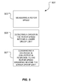
Figure 5 , amethod 501 of assisting in rotor speed control in a rotorcraft includes astep 503 of measuring a rotor speed with a sensor; atstep 505 of detecting a droop in the rotor speed beyond a lower droop limit; and astep 507 of commanding a decrease in collective in response to the rotor speed drooping beyond the lower droop limit. - The system and method of the present disclosure successfully transitions between engine throttle governing and collective pitch governing to control rotor speed. The system and method allows collective pitch governing in circumstances when rotor speed has dropped beyond a threshold that is well below normal operating ranges. The system and method prevents excessive rotor speed droop after a dual engine failure, without requiring engine failure detection. As such, it is robust to delayed engine failure detection and nuisance engine failure declarations. A dual engine failure detection is not required for initial operation, but can be used to improve long term response. One benefit of the system of the present disclosure is that it will aid the pilot in an emergency situation, greatly relieving the requirement for immediate pilot action. It reduces pilot workload after a dual engine failure.
- Referring now also to
Figure 6 , acomputer system 601 is schematically illustrated.Computer system 601 can be configured for performing one or more functions with regard to the operation of system and method further disclosed herein. Further, any processing and analysis can be partly or fully performed bycomputer system 601.Computer system 601 can be partly or fully integrated with other aircraft computer systems. - The
system 601 can include an input/output (I/O)interface 603, ananalysis engine 605, and adatabase 607. Alternative embodiments can combine or distribute the input/output (I/O)interface 603,analysis engine 605, anddatabase 607, as desired. Embodiments of thesystem 601 can include one or more computers that include one or more processors and memories configured for performing tasks described herein. This can include, for example, a computer having a central processing unit (CPU) and non-volatile memory that stores software instructions for instructing the CPU to perform at least some of the tasks described herein. This can also include, for example, two or more computers that are in communication via a computer network, where one or more of the computers include a CPU and non-volatile memory, and one or more of the computer's non-volatile memory stores software instructions for instructing any of the CPU(s) to perform any of the tasks described herein. Thus, while the exemplary embodiment is described in terms of a discrete machine, it should be appreciated that this description is non-limiting, and that the present description applies equally to numerous other arrangements involving one or more machines performing tasks distributed in any way among the one or more machines. It should also be appreciated that such machines need not be dedicated to performing tasks described herein, but instead can be multi-purpose machines, for example computer workstations, that are suitable for also performing other tasks. - The I/
O interface 603 can provide a communication link between external users, systems, and data sources and components of thesystem 601. The I/O interface 603 can be configured for allowing one or more users to input information to thesystem 601 via any known input device. Examples can include a keyboard, mouse, touch screen, and/or any other desired input device. The I/O interface 603 can be configured for allowing one or more users to receive information output from thesystem 601 via any known output device. Examples can include a display monitor, a printer, cockpit display, and/or any other desired output device. The I/O interface 603 can be configured for allowing other systems to communicate with thesystem 601. For example, the I/O interface 603 can allow one or more remote computer(s) to access information, input information, and/or remotely instruct thesystem 601 to perform one or more of the tasks described herein. The I/O interface 603 can be configured for allowing communication with one or more remote data sources. For example, the I/O interface 603 can allow one or more remote data source(s) to access information, input information, and/or remotely instruct thesystem 601 to perform one or more of the tasks described herein. - The
database 607 provides persistent data storage forsystem 601. While the term "database" is primarily used, a memory or other suitable data storage arrangement may provide the functionality of thedatabase 607. In alternative embodiments, thedatabase 607 can be integral to or separate from thesystem 601 and can operate on one or more computers. Thedatabase 607 preferably provides non-volatile data storage for any information suitable to support the operation ofsystem 201 andmethod 501, and various embodiments thereof, including various types of data discussed further herein. Theanalysis engine 605 can include various combinations of one or more processors, memories, and software components. - The particular embodiments disclosed herein are illustrative only, as the system and method may be modified and practiced in different but equivalent manners apparent to those skilled in the art having the benefit of the teachings herein. Modifications, additions, or omissions may be made to the system described herein without departing from the scope of the invention. The components of the system may be integrated or separated. Moreover, the operations of the system may be performed by more, fewer, or other components.
- Furthermore, no limitations are intended to the details of construction or design herein shown, other than as described in the claims below. It is therefore evident that the particular embodiments disclosed above may be altered or modified and all such variations are considered within the scope and spirit of the disclosure.
- To aid the Patent Office, and any readers of any patent issued on this application in interpreting the claims appended hereto, applicants wish to note that they do not intend any of the appended claims to invoke paragraph 6 of 35 U.S.C. § 112 as it exists on the date of filing hereof unless the words "means for" or "step for" are explicitly used in the particular claim.
Claims (16)
- A system of assisting in rotor speed control in a rotorcraft, the system comprising:a computer having a control law, the control law operable to generate an increase collective command to an actuator in response to a rotor speed decreasing below a lower droop limit;wherein the lower droop limit is below a normal lower rotor speed range.
- A method of assisting in rotor speed control in a rotorcraft, the method comprising:measuring a rotor speed with a sensor;detecting a droop in the rotor speed beyond a lower droop limit; andcommanding a decrease in collective in response to the rotor speed drooping beyond the lower droop limit.
- The system according to claim 1, wherein the control law is operable to generate the increase collective command without the detection of an engine failure.
- The system according to claim 1 or claim 3, further comprising:a sensor configured for measuring the rotor speed.
- The system according to claim 1 or claim 3 or claim 4, wherein the lower droop limit is a function of a difference between a commanded rotor speed and the rotor speed; or
the method of claim 2, wherein the lower droop limit is a function of a difference between a commanded rotor speed and an actual rotor speed. - The system according to claim 1 or of any of claims 3 to 5, wherein the computer is further operable to at least partially remove collective command authority from a vertical loops control law, the vertical loops control law being configured to make collective commands so that the rotorcraft can hold a desired vertical axis state; or
the method according to claim 2 or claim 5 further comprising:at least partially removing collective command authority from a vertical loops control law. - The system according to claim 1 or any of claims 3 to 6, wherein the actuator is a collective actuator configured to cause a pitch change in a rotor blade; or
the method of claim 2 or of claim 5 or of claim 6, wherein the step of commanding the decrease in collective in response to the rotor speed drooping beyond the lower droop limit includes communicating a command to a collective actuator. - The system according to claim 1 or any of claims 3 to 7, wherein the computer is a flight control computer located in the rotorcraft.
- The system according to claim 1 or any of claims 3 to 8, wherein the rotor speed decreasing below the lower droop limit is due to an undetected engine failure; or
the method of claim 2 or any of claims 5 to 7, wherein the droop in the rotor speed beyond a lower droop limit is due to an undetected engine failure. - The system according to claim 1 or any of claims 3 to 9, wherein the rotor speed decreasing below the lower droop limit is due to a pilot commanded pitch-up maneuver.
- The method according to claim 2, or any preceding method claim, wherein the lower droop limit is below a normal lower rotor speed range.
- The method according to claim 2, or any preceding method claim, further comprising:switching collective command authority to an all engine inoperative control law after a detection of an engine failure.
- The method according to claim 2, or any preceding method claim, wherein the step of detecting the droop in the rotor speed beyond the lower droop limit is performed by a computer.
- The method according to claim 2, or any preceding method claim, further comprising:adjusting the lower droop limit according to an altitude of the rotorcraft.
- The method according to claim 2, or any preceding method claim, wherein the lower droop limit is adjusted higher at lower altitudes and adjusted lower at higher altitudes.
- The method according to claim 2, or any preceding method claim, wherein a magnitude of the decrease in collective has a nonlinear relationship to an amount of the rotor speed drooping beyond the lower droop limit, such that the magnitude of the decrease in collective exponentially increases as the amount of the rotor speed drooping beyond the lower droop limit increases.
Applications Claiming Priority (2)
| Application Number | Priority Date | Filing Date | Title |
|---|---|---|---|
| US201361832186P | 2013-06-07 | 2013-06-07 | |
| US14/297,136 US9821908B2 (en) | 2013-06-07 | 2014-06-05 | System and method for assisting in rotor speed control |
Publications (2)
| Publication Number | Publication Date |
|---|---|
| EP2810873A1 true EP2810873A1 (en) | 2014-12-10 |
| EP2810873B1 EP2810873B1 (en) | 2015-09-30 |
Family
ID=50942078
Family Applications (1)
| Application Number | Title | Priority Date | Filing Date |
|---|---|---|---|
| EP14171604.3A Active EP2810873B1 (en) | 2013-06-07 | 2014-06-06 | System and method for assisting in rotor speed control |
Country Status (2)
| Country | Link |
|---|---|
| US (2) | US9821908B2 (en) |
| EP (1) | EP2810873B1 (en) |
Cited By (1)
| Publication number | Priority date | Publication date | Assignee | Title |
|---|---|---|---|---|
| EP3444187A1 (en) * | 2017-08-17 | 2019-02-20 | Bell Helicopter Textron Inc. | System and method for rotorcraft collective power hold |
Families Citing this family (18)
| Publication number | Priority date | Publication date | Assignee | Title |
|---|---|---|---|---|
| US8651425B2 (en) | 2009-11-24 | 2014-02-18 | Merlin Technology Inc. | Emergency collective actuator and method for a helicopter |
| FR3023261B1 (en) * | 2014-07-03 | 2016-07-01 | Airbus Helicopters | METHOD FOR REGULATING THE ROTATION SPEED OF THE MAIN ROTOR OF A MULTI-ENGINE GYROVATOR IN CASE OF FAILURE OF ONE OF THE ENGINES |
| US9957041B2 (en) | 2015-05-21 | 2018-05-01 | Merlin Technology, Inc. | Advanced emergency collective actuator with friction pull-off and method for a helicopter |
| US10343770B2 (en) * | 2016-03-01 | 2019-07-09 | Joe H. Mullins | Torque and pitch managed quad-rotor aircraft |
| FR3062881B1 (en) * | 2017-02-15 | 2019-03-15 | Safran Helicopter Engines | METHOD AND SYSTEM FOR CONTROLLING AN EMERGENCY DEVICE |
| US10802482B2 (en) * | 2017-02-27 | 2020-10-13 | Textron Innovations Inc. | Reverse tactile cue for rotorcraft rotor overspeed protection |
| US10377470B2 (en) | 2017-07-11 | 2019-08-13 | Bell Helicopter Textron Inc. | Rotorcraft with redundant processors using state comparison |
| US10860038B2 (en) * | 2018-02-26 | 2020-12-08 | Textron Innovations Inc. | System and method for automatic rotorcraft tail strike protection |
| US10906656B2 (en) | 2018-05-01 | 2021-02-02 | Bell Textron Inc. | Hybrid tiltrotor drive system |
| US10906637B2 (en) | 2018-05-17 | 2021-02-02 | Textron Innovations Inc. | Assisted landing systems for rotorcraft |
| US20200023955A1 (en) * | 2018-07-23 | 2020-01-23 | Textron Innovations Inc. | System and Method for Rotorcraft Flight Control |
| US10968765B2 (en) | 2018-12-04 | 2021-04-06 | General Electric Company | Power system with a coordinated power draw |
| US11643965B2 (en) * | 2019-05-15 | 2023-05-09 | Pratt & Whitney Canada Corp. | System and method for operating multi-engine rotorcraft |
| US11299286B2 (en) | 2019-05-15 | 2022-04-12 | Pratt & Whitney Canada Corp. | System and method for operating a multi-engine aircraft |
| ES2954854T3 (en) * | 2020-01-08 | 2023-11-27 | Swissdrones Operating Ag | air vehicle |
| CN115136092A (en) | 2020-02-28 | 2022-09-30 | 索尼集团公司 | Unmanned aerial vehicle, computer program and method for reducing damage to the environment due to collisions of an unmanned aerial vehicle |
| US11873081B2 (en) | 2021-06-09 | 2024-01-16 | Textron Innovations Inc. | Supplemental engine power control |
| US20240017823A1 (en) * | 2022-07-18 | 2024-01-18 | Textron Innovations Inc. | Optimizing usage of supplemental engine power |
Citations (5)
| Publication number | Priority date | Publication date | Assignee | Title |
|---|---|---|---|---|
| US4980835A (en) * | 1988-10-13 | 1990-12-25 | United Technologies Corporation | Control law system for X-Wing aircraft |
| US5951608A (en) * | 1995-12-06 | 1999-09-14 | Mcdonnell Douglas Helicopter Company | Flight control system for jet powered tri-mode aircraft |
| US20040010354A1 (en) * | 2002-06-10 | 2004-01-15 | The Boeing Company | Method, system, and computer program product for tactile cueing flight control |
| US20080243313A1 (en) * | 2007-03-26 | 2008-10-02 | Bell Helicopter Textron Inc. | Governor for a rotor with a variable maximum collective pitch |
| EP2774845A1 (en) * | 2013-03-07 | 2014-09-10 | Bell Helicopter Textron Inc. | System and method of adaptively governing rotor speed for optimal performance |
Family Cites Families (44)
| Publication number | Priority date | Publication date | Assignee | Title |
|---|---|---|---|---|
| US5265825A (en) * | 1991-08-27 | 1993-11-30 | United Technologies Corporation | Helicopter engine control having yaw input anticipation |
| US5899855A (en) | 1992-11-17 | 1999-05-04 | Health Hero Network, Inc. | Modular microprocessor-based health monitoring system |
| US5307263A (en) | 1992-11-17 | 1994-04-26 | Raya Systems, Inc. | Modular microprocessor-based health monitoring system |
| US20010011224A1 (en) | 1995-06-07 | 2001-08-02 | Stephen James Brown | Modular microprocessor-based health monitoring system |
| US5951300A (en) | 1997-03-10 | 1999-09-14 | Health Hero Network | Online system and method for providing composite entertainment and health information |
| US6968375B1 (en) | 1997-03-28 | 2005-11-22 | Health Hero Network, Inc. | Networked system for interactive communication and remote monitoring of individuals |
| US7647237B2 (en) | 1998-04-29 | 2010-01-12 | Minimed, Inc. | Communication station and software for interfacing with an infusion pump, analyte monitor, analyte meter, or the like |
| US6175752B1 (en) | 1998-04-30 | 2001-01-16 | Therasense, Inc. | Analyte monitoring device and methods of use |
| US6477424B1 (en) | 1998-06-19 | 2002-11-05 | Medtronic, Inc. | Medical management system integrated programming apparatus for communication with an implantable medical device |
| DE69926900T3 (en) | 1998-09-30 | 2012-10-04 | Medtronic Minimed, Inc. | COMMUNICATION STATION AND SOFTWARE WITH AN INFUSION PUMP, ANALYSIS MONITORING SYSTEM, ANALYTY METER, OR SIMILAR EQUIPMENT |
| US6442432B2 (en) | 1999-12-21 | 2002-08-27 | Medtronic, Inc. | Instrumentation and software for remote monitoring and programming of implantable medical devices (IMDs) |
| US6669631B2 (en) | 2000-06-14 | 2003-12-30 | Medtronic, Inc. | Deep computing applications in medical device systems |
| US7685005B2 (en) | 2000-08-29 | 2010-03-23 | Medtronic, Inc. | Medical device systems implemented network scheme for remote patient management |
| US6943787B2 (en) | 2001-02-27 | 2005-09-13 | Medtronics, Inc. | System and method for displaying implantable medical device data |
| US6957102B2 (en) | 2001-12-10 | 2005-10-18 | Medtronic Emergency Response Systems, Inc. | Enhanced interface for a medical device and a terminal |
| US20050038680A1 (en) | 2002-12-19 | 2005-02-17 | Mcmahon Kevin Lee | System and method for glucose monitoring |
| US7231258B2 (en) | 2002-12-26 | 2007-06-12 | Medtronic Physio-Control Corp. | Communicating medical event information |
| US8333714B2 (en) | 2006-09-10 | 2012-12-18 | Abbott Diabetes Care Inc. | Method and system for providing an integrated analyte sensor insertion device and data processing unit |
| US7414544B2 (en) * | 2005-01-28 | 2008-08-19 | Bell Helicopter Textron, Inc. | Power situation indicator |
| DE602006000239T2 (en) * | 2005-04-19 | 2008-09-18 | Fraunhofer-Gesellschaft zur Förderung der angewandten Forschung e.V. | ENERGY DEPENDENT QUANTIZATION FOR EFFICIENT CODING OF SPATIAL AUDIOPARAMETERS |
| US7768408B2 (en) | 2005-05-17 | 2010-08-03 | Abbott Diabetes Care Inc. | Method and system for providing data management in data monitoring system |
| US7766829B2 (en) | 2005-11-04 | 2010-08-03 | Abbott Diabetes Care Inc. | Method and system for providing basal profile modification in analyte monitoring and management systems |
| US7976310B2 (en) * | 2006-01-13 | 2011-07-12 | Systems Technology, Inc. | Autorotation flight control system |
| US7618369B2 (en) | 2006-10-02 | 2009-11-17 | Abbott Diabetes Care Inc. | Method and system for dynamically updating calibration parameters for an analyte sensor |
| US9058590B2 (en) | 2006-04-10 | 2015-06-16 | Microsoft Technology Licensing, Llc | Content upload safety tool |
| US20090112769A1 (en) | 2007-10-24 | 2009-04-30 | Kent Dicks | Systems and methods for remote patient monitoring |
| US8579853B2 (en) | 2006-10-31 | 2013-11-12 | Abbott Diabetes Care Inc. | Infusion devices and methods |
| US20080270802A1 (en) | 2007-04-24 | 2008-10-30 | Paul Anthony Ashley | Method and system for protecting personally identifiable information |
| US8103471B2 (en) | 2007-05-14 | 2012-01-24 | Abbott Diabetes Care Inc. | Method and apparatus for providing data processing and control in a medical communication system |
| FR2916421B1 (en) * | 2007-05-22 | 2010-04-23 | Eurocopter France | SYSTEM FOR CONTROLLING A GIRAVION. |
| US8409093B2 (en) | 2007-10-23 | 2013-04-02 | Abbott Diabetes Care Inc. | Assessing measures of glycemic variability |
| FR2943131B1 (en) * | 2009-03-12 | 2011-02-25 | Eurocopter France | METHOD FOR DETERMINING AND DISPLAYING STEERING INDICATIONS AND STEERING INDICATOR FOR CARRYING OUT SAID METHOD |
| FI20095791A0 (en) | 2009-07-15 | 2009-07-15 | Ihq Medical Inc | Procedure and arrangements for checking measurement |
| US8360369B2 (en) | 2009-11-24 | 2013-01-29 | Merlin Technology, Inc. | Emergency collective actuator and method for a helicopter |
| US8651425B2 (en) | 2009-11-24 | 2014-02-18 | Merlin Technology Inc. | Emergency collective actuator and method for a helicopter |
| US20110288884A1 (en) | 2010-05-21 | 2011-11-24 | Richard Algoo | Providing medical services and/or products using telecommunications |
| US8475367B1 (en) | 2011-01-09 | 2013-07-02 | Fitbit, Inc. | Biometric monitoring device having a body weight sensor, and methods of operating same |
| US20120182939A1 (en) | 2011-01-14 | 2012-07-19 | Qualcomm Incorporated | Telehealth wireless communication hub and service platform system |
| US8811888B2 (en) | 2011-01-14 | 2014-08-19 | Covidien Lp | Wireless relay module for monitoring network status |
| WO2013052937A1 (en) | 2011-10-06 | 2013-04-11 | Nant Holdings Ip, Llc | Healthcare object recognition systems and methods |
| US9193450B2 (en) * | 2012-02-24 | 2015-11-24 | Bell Helicopter Textron Inc. | System and method for automation of rotorcraft entry into autorotation and maintenance of stabilized autorotation |
| US9567091B2 (en) * | 2013-06-06 | 2017-02-14 | Bell Helicopter Textron Inc. | System and method for maximizing aircraft safe landing capability during one engine inoperative operation |
| US9856017B2 (en) * | 2013-06-11 | 2018-01-02 | Bell Helicopter Textron Inc. | Torque based method of limiting vertical axis augmentation |
| US9957041B2 (en) | 2015-05-21 | 2018-05-01 | Merlin Technology, Inc. | Advanced emergency collective actuator with friction pull-off and method for a helicopter |
-
2014
- 2014-06-05 US US14/297,136 patent/US9821908B2/en active Active
- 2014-06-06 EP EP14171604.3A patent/EP2810873B1/en active Active
-
2017
- 2017-07-05 US US15/642,279 patent/US10392105B2/en active Active
Patent Citations (5)
| Publication number | Priority date | Publication date | Assignee | Title |
|---|---|---|---|---|
| US4980835A (en) * | 1988-10-13 | 1990-12-25 | United Technologies Corporation | Control law system for X-Wing aircraft |
| US5951608A (en) * | 1995-12-06 | 1999-09-14 | Mcdonnell Douglas Helicopter Company | Flight control system for jet powered tri-mode aircraft |
| US20040010354A1 (en) * | 2002-06-10 | 2004-01-15 | The Boeing Company | Method, system, and computer program product for tactile cueing flight control |
| US20080243313A1 (en) * | 2007-03-26 | 2008-10-02 | Bell Helicopter Textron Inc. | Governor for a rotor with a variable maximum collective pitch |
| EP2774845A1 (en) * | 2013-03-07 | 2014-09-10 | Bell Helicopter Textron Inc. | System and method of adaptively governing rotor speed for optimal performance |
Cited By (2)
| Publication number | Priority date | Publication date | Assignee | Title |
|---|---|---|---|---|
| EP3444187A1 (en) * | 2017-08-17 | 2019-02-20 | Bell Helicopter Textron Inc. | System and method for rotorcraft collective power hold |
| US10479491B2 (en) | 2017-08-17 | 2019-11-19 | Textron Innovations Inc. | System and method for rotorcraft collective power hold |
Also Published As
| Publication number | Publication date |
|---|---|
| EP2810873B1 (en) | 2015-09-30 |
| US20140363288A1 (en) | 2014-12-11 |
| US20170297695A1 (en) | 2017-10-19 |
| US10392105B2 (en) | 2019-08-27 |
| US9821908B2 (en) | 2017-11-21 |
Similar Documents
| Publication | Publication Date | Title |
|---|---|---|
| US10392105B2 (en) | System and method for assisting in rotor speed control | |
| US11383829B2 (en) | System and method for automation of rotorcraft entry into autorotation and maintenance of stabilized autorotation | |
| US11208205B2 (en) | System and method for rotorcraft autorotation entry assist | |
| US9567091B2 (en) | System and method for maximizing aircraft safe landing capability during one engine inoperative operation | |
| EP2774845B1 (en) | System and method of adaptively governing rotor speed for optimal performance | |
| US10479491B2 (en) | System and method for rotorcraft collective power hold | |
| US20200285232A1 (en) | Reverse Tactile Cue for Rotorcraft Rotor Overspeed Protection | |
| US9886039B2 (en) | System and method for avoiding inadvertant entry into an unsafe vertical descent speed region for rotorcraft | |
| US20230150656A1 (en) | System and Method for Protection Against Vortex Ring State | |
| US11048273B2 (en) | System and method for rotorcraft height control | |
| US11117653B2 (en) | System and method for tactile cueing through rotorcraft pilot controls using variable friction and force gradient | |
| EP2813427B1 (en) | Torque-based method of limiting vertical axis augmentation | |
| EP3326911A1 (en) | Rotor speed control using a feed-forward rotor speed command | |
| EP3569497A1 (en) | System and method for tactile cueing through rotorcraft pilot controls using variable friction and force gradient |
Legal Events
| Date | Code | Title | Description |
|---|---|---|---|
| PUAI | Public reference made under article 153(3) epc to a published international application that has entered the european phase |
Free format text: ORIGINAL CODE: 0009012 |
|
| 17P | Request for examination filed |
Effective date: 20140606 |
|
| AK | Designated contracting states |
Kind code of ref document: A1 Designated state(s): AL AT BE BG CH CY CZ DE DK EE ES FI FR GB GR HR HU IE IS IT LI LT LU LV MC MK MT NL NO PL PT RO RS SE SI SK SM TR |
|
| AX | Request for extension of the european patent |
Extension state: BA ME |
|
| 17Q | First examination report despatched |
Effective date: 20141113 |
|
| GRAP | Despatch of communication of intention to grant a patent |
Free format text: ORIGINAL CODE: EPIDOSNIGR1 |
|
| RIN1 | Information on inventor provided before grant (corrected) |
Inventor name: O'NEILL, ERIC Inventor name: PATEL, JIGNESH Inventor name: SCHAEFFER, JOSEPH M. |
|
| INTG | Intention to grant announced |
Effective date: 20150709 |
|
| GRAS | Grant fee paid |
Free format text: ORIGINAL CODE: EPIDOSNIGR3 |
|
| GRAA | (expected) grant |
Free format text: ORIGINAL CODE: 0009210 |
|
| AK | Designated contracting states |
Kind code of ref document: B1 Designated state(s): AL AT BE BG CH CY CZ DE DK EE ES FI FR GB GR HR HU IE IS IT LI LT LU LV MC MK MT NL NO PL PT RO RS SE SI SK SM TR |
|
| REG | Reference to a national code |
Ref country code: CH Ref legal event code: EP Ref country code: GB Ref legal event code: FG4D |
|
| REG | Reference to a national code |
Ref country code: AT Ref legal event code: REF Ref document number: 752221 Country of ref document: AT Kind code of ref document: T Effective date: 20151015 |
|
| REG | Reference to a national code |
Ref country code: IE Ref legal event code: FG4D |
|
| REG | Reference to a national code |
Ref country code: DE Ref legal event code: R096 Ref document number: 602014000285 Country of ref document: DE |
|
| PG25 | Lapsed in a contracting state [announced via postgrant information from national office to epo] |
Ref country code: GR Free format text: LAPSE BECAUSE OF FAILURE TO SUBMIT A TRANSLATION OF THE DESCRIPTION OR TO PAY THE FEE WITHIN THE PRESCRIBED TIME-LIMIT Effective date: 20151231 Ref country code: FI Free format text: LAPSE BECAUSE OF FAILURE TO SUBMIT A TRANSLATION OF THE DESCRIPTION OR TO PAY THE FEE WITHIN THE PRESCRIBED TIME-LIMIT Effective date: 20150930 Ref country code: LT Free format text: LAPSE BECAUSE OF FAILURE TO SUBMIT A TRANSLATION OF THE DESCRIPTION OR TO PAY THE FEE WITHIN THE PRESCRIBED TIME-LIMIT Effective date: 20150930 Ref country code: NO Free format text: LAPSE BECAUSE OF FAILURE TO SUBMIT A TRANSLATION OF THE DESCRIPTION OR TO PAY THE FEE WITHIN THE PRESCRIBED TIME-LIMIT Effective date: 20151230 Ref country code: LV Free format text: LAPSE BECAUSE OF FAILURE TO SUBMIT A TRANSLATION OF THE DESCRIPTION OR TO PAY THE FEE WITHIN THE PRESCRIBED TIME-LIMIT Effective date: 20150930 |
|
| REG | Reference to a national code |
Ref country code: NL Ref legal event code: MP Effective date: 20150930 |
|
| REG | Reference to a national code |
Ref country code: LT Ref legal event code: MG4D |
|
| REG | Reference to a national code |
Ref country code: AT Ref legal event code: MK05 Ref document number: 752221 Country of ref document: AT Kind code of ref document: T Effective date: 20150930 |
|
| PG25 | Lapsed in a contracting state [announced via postgrant information from national office to epo] |
Ref country code: HR Free format text: LAPSE BECAUSE OF FAILURE TO SUBMIT A TRANSLATION OF THE DESCRIPTION OR TO PAY THE FEE WITHIN THE PRESCRIBED TIME-LIMIT Effective date: 20150930 Ref country code: RS Free format text: LAPSE BECAUSE OF FAILURE TO SUBMIT A TRANSLATION OF THE DESCRIPTION OR TO PAY THE FEE WITHIN THE PRESCRIBED TIME-LIMIT Effective date: 20150930 Ref country code: SE Free format text: LAPSE BECAUSE OF FAILURE TO SUBMIT A TRANSLATION OF THE DESCRIPTION OR TO PAY THE FEE WITHIN THE PRESCRIBED TIME-LIMIT Effective date: 20150930 |
|
| PG25 | Lapsed in a contracting state [announced via postgrant information from national office to epo] |
Ref country code: ES Free format text: LAPSE BECAUSE OF FAILURE TO SUBMIT A TRANSLATION OF THE DESCRIPTION OR TO PAY THE FEE WITHIN THE PRESCRIBED TIME-LIMIT Effective date: 20150930 Ref country code: IS Free format text: LAPSE BECAUSE OF FAILURE TO SUBMIT A TRANSLATION OF THE DESCRIPTION OR TO PAY THE FEE WITHIN THE PRESCRIBED TIME-LIMIT Effective date: 20160130 Ref country code: SK Free format text: LAPSE BECAUSE OF FAILURE TO SUBMIT A TRANSLATION OF THE DESCRIPTION OR TO PAY THE FEE WITHIN THE PRESCRIBED TIME-LIMIT Effective date: 20150930 Ref country code: NL Free format text: LAPSE BECAUSE OF FAILURE TO SUBMIT A TRANSLATION OF THE DESCRIPTION OR TO PAY THE FEE WITHIN THE PRESCRIBED TIME-LIMIT Effective date: 20150930 Ref country code: EE Free format text: LAPSE BECAUSE OF FAILURE TO SUBMIT A TRANSLATION OF THE DESCRIPTION OR TO PAY THE FEE WITHIN THE PRESCRIBED TIME-LIMIT Effective date: 20150930 Ref country code: CZ Free format text: LAPSE BECAUSE OF FAILURE TO SUBMIT A TRANSLATION OF THE DESCRIPTION OR TO PAY THE FEE WITHIN THE PRESCRIBED TIME-LIMIT Effective date: 20150930 |
|
| PG25 | Lapsed in a contracting state [announced via postgrant information from national office to epo] |
Ref country code: AT Free format text: LAPSE BECAUSE OF FAILURE TO SUBMIT A TRANSLATION OF THE DESCRIPTION OR TO PAY THE FEE WITHIN THE PRESCRIBED TIME-LIMIT Effective date: 20150930 Ref country code: PT Free format text: LAPSE BECAUSE OF FAILURE TO SUBMIT A TRANSLATION OF THE DESCRIPTION OR TO PAY THE FEE WITHIN THE PRESCRIBED TIME-LIMIT Effective date: 20160201 Ref country code: PL Free format text: LAPSE BECAUSE OF FAILURE TO SUBMIT A TRANSLATION OF THE DESCRIPTION OR TO PAY THE FEE WITHIN THE PRESCRIBED TIME-LIMIT Effective date: 20150930 Ref country code: RO Free format text: LAPSE BECAUSE OF FAILURE TO SUBMIT A TRANSLATION OF THE DESCRIPTION OR TO PAY THE FEE WITHIN THE PRESCRIBED TIME-LIMIT Effective date: 20150930 |
|
| REG | Reference to a national code |
Ref country code: FR Ref legal event code: PLFP Year of fee payment: 3 |
|
| REG | Reference to a national code |
Ref country code: DE Ref legal event code: R097 Ref document number: 602014000285 Country of ref document: DE |
|
| PLBE | No opposition filed within time limit |
Free format text: ORIGINAL CODE: 0009261 |
|
| STAA | Information on the status of an ep patent application or granted ep patent |
Free format text: STATUS: NO OPPOSITION FILED WITHIN TIME LIMIT |
|
| PG25 | Lapsed in a contracting state [announced via postgrant information from national office to epo] |
Ref country code: DK Free format text: LAPSE BECAUSE OF FAILURE TO SUBMIT A TRANSLATION OF THE DESCRIPTION OR TO PAY THE FEE WITHIN THE PRESCRIBED TIME-LIMIT Effective date: 20150930 |
|
| 26N | No opposition filed |
Effective date: 20160701 |
|
| PG25 | Lapsed in a contracting state [announced via postgrant information from national office to epo] |
Ref country code: SI Free format text: LAPSE BECAUSE OF FAILURE TO SUBMIT A TRANSLATION OF THE DESCRIPTION OR TO PAY THE FEE WITHIN THE PRESCRIBED TIME-LIMIT Effective date: 20150930 |
|
| PG25 | Lapsed in a contracting state [announced via postgrant information from national office to epo] |
Ref country code: BE Free format text: LAPSE BECAUSE OF FAILURE TO SUBMIT A TRANSLATION OF THE DESCRIPTION OR TO PAY THE FEE WITHIN THE PRESCRIBED TIME-LIMIT Effective date: 20150930 |
|
| PG25 | Lapsed in a contracting state [announced via postgrant information from national office to epo] |
Ref country code: MC Free format text: LAPSE BECAUSE OF FAILURE TO SUBMIT A TRANSLATION OF THE DESCRIPTION OR TO PAY THE FEE WITHIN THE PRESCRIBED TIME-LIMIT Effective date: 20150930 |
|
| REG | Reference to a national code |
Ref country code: IE Ref legal event code: MM4A |
|
| PG25 | Lapsed in a contracting state [announced via postgrant information from national office to epo] |
Ref country code: IE Free format text: LAPSE BECAUSE OF NON-PAYMENT OF DUE FEES Effective date: 20160606 |
|
| REG | Reference to a national code |
Ref country code: FR Ref legal event code: PLFP Year of fee payment: 4 |
|
| REG | Reference to a national code |
Ref country code: CH Ref legal event code: PL |
|
| PG25 | Lapsed in a contracting state [announced via postgrant information from national office to epo] |
Ref country code: LI Free format text: LAPSE BECAUSE OF NON-PAYMENT OF DUE FEES Effective date: 20170630 Ref country code: CH Free format text: LAPSE BECAUSE OF NON-PAYMENT OF DUE FEES Effective date: 20170630 |
|
| PG25 | Lapsed in a contracting state [announced via postgrant information from national office to epo] |
Ref country code: HU Free format text: LAPSE BECAUSE OF FAILURE TO SUBMIT A TRANSLATION OF THE DESCRIPTION OR TO PAY THE FEE WITHIN THE PRESCRIBED TIME-LIMIT; INVALID AB INITIO Effective date: 20140606 Ref country code: SM Free format text: LAPSE BECAUSE OF FAILURE TO SUBMIT A TRANSLATION OF THE DESCRIPTION OR TO PAY THE FEE WITHIN THE PRESCRIBED TIME-LIMIT Effective date: 20150930 |
|
| REG | Reference to a national code |
Ref country code: FR Ref legal event code: PLFP Year of fee payment: 5 |
|
| PG25 | Lapsed in a contracting state [announced via postgrant information from national office to epo] |
Ref country code: MT Free format text: LAPSE BECAUSE OF NON-PAYMENT OF DUE FEES Effective date: 20160630 Ref country code: LU Free format text: LAPSE BECAUSE OF NON-PAYMENT OF DUE FEES Effective date: 20160606 Ref country code: MK Free format text: LAPSE BECAUSE OF FAILURE TO SUBMIT A TRANSLATION OF THE DESCRIPTION OR TO PAY THE FEE WITHIN THE PRESCRIBED TIME-LIMIT Effective date: 20150930 Ref country code: CY Free format text: LAPSE BECAUSE OF FAILURE TO SUBMIT A TRANSLATION OF THE DESCRIPTION OR TO PAY THE FEE WITHIN THE PRESCRIBED TIME-LIMIT Effective date: 20150930 |
|
| PG25 | Lapsed in a contracting state [announced via postgrant information from national office to epo] |
Ref country code: BG Free format text: LAPSE BECAUSE OF FAILURE TO SUBMIT A TRANSLATION OF THE DESCRIPTION OR TO PAY THE FEE WITHIN THE PRESCRIBED TIME-LIMIT Effective date: 20150930 |
|
| PG25 | Lapsed in a contracting state [announced via postgrant information from national office to epo] |
Ref country code: AL Free format text: LAPSE BECAUSE OF FAILURE TO SUBMIT A TRANSLATION OF THE DESCRIPTION OR TO PAY THE FEE WITHIN THE PRESCRIBED TIME-LIMIT Effective date: 20150930 Ref country code: TR Free format text: LAPSE BECAUSE OF FAILURE TO SUBMIT A TRANSLATION OF THE DESCRIPTION OR TO PAY THE FEE WITHIN THE PRESCRIBED TIME-LIMIT Effective date: 20150930 |
|
| P01 | Opt-out of the competence of the unified patent court (upc) registered |
Effective date: 20230602 |
|
| PGFP | Annual fee paid to national office [announced via postgrant information from national office to epo] |
Ref country code: FR Payment date: 20230626 Year of fee payment: 10 Ref country code: DE Payment date: 20230626 Year of fee payment: 10 |
|
| PGFP | Annual fee paid to national office [announced via postgrant information from national office to epo] |
Ref country code: IT Payment date: 20230620 Year of fee payment: 10 Ref country code: GB Payment date: 20230627 Year of fee payment: 10 |