EP2810504B1 - Method and device for facilitating location approximation in a cdma 1x network - Google Patents
Method and device for facilitating location approximation in a cdma 1x network Download PDFInfo
- Publication number
- EP2810504B1 EP2810504B1 EP13702174.7A EP13702174A EP2810504B1 EP 2810504 B1 EP2810504 B1 EP 2810504B1 EP 13702174 A EP13702174 A EP 13702174A EP 2810504 B1 EP2810504 B1 EP 2810504B1
- Authority
- EP
- European Patent Office
- Prior art keywords
- system information
- access terminal
- base station
- serving base
- determining
- Prior art date
- Legal status (The legal status is an assumption and is not a legal conclusion. Google has not performed a legal analysis and makes no representation as to the accuracy of the status listed.)
- Active
Links
- 238000000034 method Methods 0.000 title claims description 44
- 238000004891 communication Methods 0.000 claims description 50
- 230000004807 localization Effects 0.000 claims description 8
- 230000004044 response Effects 0.000 claims description 6
- 238000004590 computer program Methods 0.000 claims description 2
- 238000012545 processing Methods 0.000 description 44
- 230000006870 function Effects 0.000 description 22
- 230000008569 process Effects 0.000 description 17
- 238000010586 diagram Methods 0.000 description 15
- 230000005540 biological transmission Effects 0.000 description 7
- 239000000969 carrier Substances 0.000 description 3
- 230000011664 signaling Effects 0.000 description 3
- 230000003287 optical effect Effects 0.000 description 2
- 230000003321 amplification Effects 0.000 description 1
- 230000001413 cellular effect Effects 0.000 description 1
- 239000003795 chemical substances by application Substances 0.000 description 1
- 239000012141 concentrate Substances 0.000 description 1
- 230000003750 conditioning effect Effects 0.000 description 1
- 238000009795 derivation Methods 0.000 description 1
- 238000013461 design Methods 0.000 description 1
- 238000011161 development Methods 0.000 description 1
- 238000005516 engineering process Methods 0.000 description 1
- 238000001914 filtration Methods 0.000 description 1
- 238000013507 mapping Methods 0.000 description 1
- 238000012986 modification Methods 0.000 description 1
- 230000004048 modification Effects 0.000 description 1
- 238000003199 nucleic acid amplification method Methods 0.000 description 1
- 230000001105 regulatory effect Effects 0.000 description 1
- 230000000717 retained effect Effects 0.000 description 1
- 238000012552 review Methods 0.000 description 1
- 230000001360 synchronised effect Effects 0.000 description 1
Images


Classifications
-
- H—ELECTRICITY
- H04—ELECTRIC COMMUNICATION TECHNIQUE
- H04W—WIRELESS COMMUNICATION NETWORKS
- H04W4/00—Services specially adapted for wireless communication networks; Facilities therefor
- H04W4/02—Services making use of location information
- H04W4/025—Services making use of location information using location based information parameters
-
- G—PHYSICS
- G01—MEASURING; TESTING
- G01S—RADIO DIRECTION-FINDING; RADIO NAVIGATION; DETERMINING DISTANCE OR VELOCITY BY USE OF RADIO WAVES; LOCATING OR PRESENCE-DETECTING BY USE OF THE REFLECTION OR RERADIATION OF RADIO WAVES; ANALOGOUS ARRANGEMENTS USING OTHER WAVES
- G01S5/00—Position-fixing by co-ordinating two or more direction or position line determinations; Position-fixing by co-ordinating two or more distance determinations
- G01S5/02—Position-fixing by co-ordinating two or more direction or position line determinations; Position-fixing by co-ordinating two or more distance determinations using radio waves
- G01S5/0205—Details
- G01S5/0236—Assistance data, e.g. base station almanac
-
- H—ELECTRICITY
- H04—ELECTRIC COMMUNICATION TECHNIQUE
- H04W—WIRELESS COMMUNICATION NETWORKS
- H04W64/00—Locating users or terminals or network equipment for network management purposes, e.g. mobility management
-
- H—ELECTRICITY
- H04—ELECTRIC COMMUNICATION TECHNIQUE
- H04W—WIRELESS COMMUNICATION NETWORKS
- H04W64/00—Locating users or terminals or network equipment for network management purposes, e.g. mobility management
- H04W64/006—Locating users or terminals or network equipment for network management purposes, e.g. mobility management with additional information processing, e.g. for direction or speed determination
Definitions
- Embodiments of the present invention relate generally to wireless communication, and more specifically to methods and devices for determining a location and/or location information of a wireless access terminal.
- Wireless communications systems are widely deployed to provide various types of communication content such as voice, video, packet data, messaging, broadcast, and so on. These systems may be accessed by various types of access terminals adapted to facilitate wireless communications, where multiple access terminals share the available system resources (e.g., time, frequency, and power). Examples of such wireless communications systems include code-division multiple access (CDMA) systems, time- division multiple access (TDMA) systems, frequency-division multiple access (FDMA) systems and orthogonal frequency-division multiple access (OFDMA) systems.
- CDMA code-division multiple access
- TDMA time- division multiple access
- FDMA frequency-division multiple access
- OFDMA orthogonal frequency-division multiple access
- Mobile devices used in such wireless communication systems frequently include one or more means of determining their position. These can include but are not limited to the use of global positioning satellites (GPS) and trilateration techniques such as advanced forward link trilateration (AFLT). Each of these positioning techniques generally brings different advantages and disadvantages, providing different trade-offs of accuracy, battery consumption, availability in different areas, etc. The desire for always-available and highly accurate positioning information in concert with the least amount of battery consumption is always desired, and the development of positioning technologies has continued. Examples can be found in patent documents WO2011/028452 and WO2007/001660 . Embodiments of the present invention are provisioned to address these issues as well as others
- the access terminal retrieves system information from its current serving cell and stores the retrieved system information in memory along with an associated timestamp. Over time, as the access terminal moves about the network, it can accumulate system information for a plurality of base stations within its memory. By utilizing system information for a plurality of base stations rather than only the current serving base station, as well as the associated timestamps, additional position information can be provided to the access terminal.
- Such an apparatus can include a communications interface (e.g., receiver, transmitter, or transceiver).
- the communications interface can be operatively coupled to a processing module (or controller module).
- the apparatus can also include a memory coupled to the processing module.
- the processing module can be configured to obtain position information about the communication apparatus.
- This processing module can also be configured to analyze system information from multiple base stations (e.g., a first BS, a second BS, a current serving BS, and one or more prior serving BSs). By analyzing BS system information in concert with position information about the communication apparatus, the processing module can be used to localize the communications apparatus.
- the positioning information may then be passed on to applications that can use the positioning data as a user may desire or to other network components for their use.
- the disclosure provides a method of positioning a wireless access terminal, including determining to retrieve position information corresponding to the access terminal, determining system information corresponding to a current serving base station, storing the system information in a memory, storing an associated timestamp with the system information, and transmitting the system information and the associated timestamp for the current serving base station and for at least one prior serving base station, for localization of the access terminal.
- an access terminal configured for wireless communication, including means for determining to retrieve position information corresponding to the access terminal, means for determining system information corresponding to a current serving base station, means for storing the system information, means for storing an associated timestamp with the system information, and means for transmitting the system information and the associated timestamp for the current serving base station and for at least one prior serving base station, for localization of the access terminal.
- the computer-readable storage medium includes instructions for causing a computer to determine to retrieve position information corresponding to the access terminal, to determine system information corresponding to a current serving base station, to store the system information in a memory, to store an associated timestamp with the system information, and to transmit the system information and the associated timestamp for the current serving base station and for at least one prior serving base station, for localization of the access terminal.
- an access terminal configured for wireless communication, including a processing circuit, a communications interface communicatively coupled to the processing circuit for transmitting and receiving information, and a memory communicatively coupled to the processing circuit for storing information, wherein the processing circuit is configured to determine to retrieve position information corresponding to the access terminal, to determine system information corresponding to a current serving base station, to store the system information in the memory, to store an associated timestamp with the system information, and to transmit the system information and the associated timestamp for the current serving base station and for at least one prior serving base station, for localization of the access terminal.
- an “access terminal” refers generally to one or more devices that communicate with one or more other devices through wireless signals.
- Such access terminals may also be referred to by those skilled in the art as a user equipment (UE), a mobile station (MS), a subscriber station, a mobile unit, a subscriber unit, a wireless unit, a remote unit, a mobile device, a wireless device, a wireless communications device, a remote device, a mobile subscriber station, a mobile terminal, a wireless terminal, a remote terminal, a handset, a terminal, a user agent, a mobile client, a client, or some other suitable terminology.
- Access terminals may include mobile terminals, at least substantially fixed terminals, and/or stationary communication components.
- access terminals include mobile phones, pagers, wireless modems, personal digital assistants, personal information managers (PIMs), personal media players, palmtop computers, laptop computers, tablet computers, televisions, appliances, e-readers, digital video recorders (DVRs), machine-to-machine (M2M) devices, routers, smartphones, entertainment devices, and/or other communication/computing devices which communicate, at least partially, through a wireless or cellular network.
- PIMs personal information managers
- DVRs digital video recorders
- M2M machine-to-machine
- programming shall be construed broadly to include without limitation instructions, instruction sets, code, code segments, program code, programs, subprograms, software modules, applications, software applications, software packages, routines, subroutines, objects, executables, threads of execution, procedures, functions, etc., whether referred to as software, firmware, middleware, microcode, hardware description language, or otherwise.
- FIG. 1 is a conceptual diagram illustrating an example of a network environment in which one or more aspects of the present disclosure may find application.
- the wireless communication system 100 generally includes one or more base stations 102, one or more access terminals 104, one or more base station controllers (BSC) 106, and a core network 108 providing access to a public switched telephone network (PSTN) (e.g., via a mobile switching center/visitor location register (MSC/VLR)) and/or to an IP network (e.g., via a packet data switching node (PDSN)).
- PSTN public switched telephone network
- MSC/VLR mobile switching center/visitor location register
- IP network e.g., via a packet data switching node (PDSN)
- the system 100 may support operation on multiple carriers (waveform signals of different frequencies). Multi-carrier transmitters can transmit modulated signals simultaneously on the multiple carriers.
- Each modulated signal may be a CDMA signal, a TDMA signal, an OFDMA signal, a Single Carrier Frequency Division Multiple Access (SC-FDMA) signal, etc.
- Each modulated signal may be sent on a different carrier and may carry control information (e.g., pilot signals), overhead information, data, etc.
- the base stations 102 may wirelessly communicate with the access terminals 104 via a base station antenna.
- the base stations 102 may each include a device that facilitates wireless connectivity (for one or more access terminals 104) to the wireless communications system 100.
- the base stations 102 may include access points, base transceiver stations (BTS), radio base stations, radio transceivers, transceiver functions, basic service sets (BSS), extended service sets (ESS), Node Bs, femto cells, pico cells, and/or some other suitable device.
- the base stations 102 are configured to communicate with the access terminals 104 under the control of the base station controller 106 via multiple carriers. Each of the base stations 102 can provide communication coverage for a respective geographic area.
- the coverage area 110 for each base station 102 here is identified as cells 110-a, 110-b, or 110-c.
- the coverage area 110 for a base station 102 may be divided into sectors (not shown, but making up only a portion of the coverage area). In a coverage area 110 that is divided into sectors, the multiple sectors within a coverage area 110 can be formed by groups of antennas with each antenna responsible for communication with one or more access terminals 104 in a portion of the cell.
- the access terminals 104 may be dispersed throughout the coverage areas 110, and may wirelessly communicate with one or more sectors associated with each respective base station 102.
- the access terminal 104 may be adapted to employ a protocol stack architecture for communicating data between the access terminal 104 and one or more network nodes of the wireless communication system 100 (e.g., the base station 102).
- a protocol stack generally includes a conceptual model of the layered architecture for communication protocols.
- the layers are represented in order of their numeric designation, where transferred data is processed sequentially by each layer, in the order of their representation. Graphically, the "stack" is typically shown vertically, with the layer having the lowest numeric designation at the base.
- FIG. 2 is a block diagram illustrating an example of a protocol stack architecture which may be implemented by an access terminal 104.
- the protocol stack architecture for the access terminal 104 is shown with three layers: Layer 1 (L1), Layer 2 (L2), and Layer 3 (L3).
- Layer 1 202 is the lowest layer and implements various physical layer signal processing functions. Layer 1 202 is also referred to herein as the physical layer 202. This physical layer 202 provides for the transmission and reception of radio signals between the access terminal 104 and a base station 102.
- the data link layer, called layer 2 (or “the L2 layer”) 204 is above the physical layer 202 and is responsible for delivery of signaling messages generated by Layer 3.
- the L2 layer 204 makes use of the services provided by the physical layer 202.
- the L2 layer 204 may include two sublayers: the Medium Access Control (MAC) sublayer 206, and the Link Access Control (LAC) sublayer 208.
- MAC Medium Access Control
- LAC Link Access Control
- the MAC sublayer 206 is the lower sublayer of the L2 layer 204.
- the MAC sublayer 206 implements the medium access protocol and is responsible for transport of higher layers' protocol data units using the services provided by the physical layer 202.
- the MAC sublayer 206 may manage the access of data from the higher layers to the shared air interface.
- the LAC sublayer 208 is the upper sublayer of the L2 layer 204.
- the LAC sublayer 208 implements a data link protocol that provides for the correct transport and delivery of signaling messages generated at the layer 3.
- the LAC sublayer makes use of the services provided by the lower layers (e.g., layer 1 and the MAC sublayer).
- Layer 3 210 which may also be referred to as the upper layer or the L3 layer, originates and terminates signaling messages according to the semantics and timing of the communication protocol between a base station 102 and the access terminal 104.
- the L3 layer 210 makes use of the services provided by the L2 layer.
- Information (both data and voice) message are also passed through the L3 layer 210.
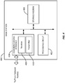
- FIG. 3 is a block diagram illustrating select components of an access terminal 300 adapted to employ such features according to at least one example.
- the access terminal 300 may include a processing circuit 302 coupled to a communications interface 304 and to a storage medium 306.
- the processing circuit 302 is arranged to obtain, process and/or send data, control data access and storage, issue commands, and control other desired operations.
- the processing circuit 302 may include circuitry configured to implement desired programming provided by appropriate media in at least one embodiment.
- the processing circuit 302 may be implemented as one or more of a processor, a controller, a plurality of processors and/or other structure configured to execute executable instructions including, for example, software and/or firmware instructions, and/or hardware circuitry.
- Examples of the processing circuit 302 may include a general purpose processor, a digital signal processor (DSP), an application specific integrated circuit (ASIC), a field programmable gate array (FPGA) or other programmable logic component, discrete gate or transistor logic, discrete hardware components, or any combination thereof designed to perform the functions described herein.
- a general purpose processor may be a microprocessor but, in the alternative, the processor may be any conventional processor, controller, microcontroller, or state machine.
- a processor may also be implemented as a combination of computing components, such as a combination of a DSP and a microprocessor, a number of microprocessors, one or more microprocessors in conjunction with a DSP core, or any other such configuration.
- These examples of the processing circuit 302 are for illustration and other suitable configurations within the scope of the present disclosure are also contemplated.
- the processing circuit 302 is adapted for processing, including the execution of programming, which may be stored on the storage medium 306.
- the processing circuit 302 may include system information gathering circuitry 312.
- the system information gathering circuitry 312 may include circuitry and/or programming adapted to utilize the transmitter 310 and/or the receiver 308 to retrieve system information corresponding to one or more base stations, for the positioning of the access terminal 300.
- the communications interface 304 is configured to facilitate wireless communications of the access terminal 300.
- the communications interface 304 may include circuitry and/or programming adapted to facilitate the communication of information bi-directionally with respect to one or more network nodes.
- the communications interface 304 may be coupled to one or more antennas (not shown), and includes wireless transceiver circuitry, including at least one receiver circuit 308 (e.g., one or more receiver chains) and/or at least one transmitter circuit 310 (e.g., one or more transmitter chains).
- the at least one transmitter circuit 310 may include circuitry, devices and/or programming adapted to provide various signal conditioning functions including amplification, filtering, and modulating transmission frames onto a carrier for uplink transmission over a wireless medium through an antenna.
- the storage medium 306 may represent one or more devices for storing programming and/or data, such as processor executable code or instructions (e.g., software, firmware), electronic data, databases, or other digital information.
- the storage medium 306 may also be used for storing data that is manipulated by the processing circuit 302 when executing programming.
- the storage medium 306 may be any available media that can be accessed by a general purpose or special purpose processor.
- the storage medium 306 may include a non-transitory computer-readable medium such as a magnetic storage device (e.g., hard disk, floppy disk, magnetic strip), an optical storage medium (e.g., compact disk (CD), digital versatile disk (DVD)), a smart card, a flash memory device (e.g., card, stick, key drive), random access memory (RAM), read only memory (ROM), programmable ROM (PROM), erasable PROM (EPROM), electrically erasable PROM (EEPROM), a register, a removable disk, and/or other non-transitory computer-readable mediums for storing information, as well as any combination thereof.
- a magnetic storage device e.g., hard disk, floppy disk, magnetic strip
- an optical storage medium e.g., compact disk (CD), digital versatile disk (DVD)
- a smart card e.g., a flash memory device (e.g., card, stick, key drive), random access memory (RAM), read only memory (ROM
- the storage medium 306 may be coupled to, or at least accessible by the processing circuit 302 such that the processing circuit 302 can read information from, and write information to, the storage medium 306.
- the storage medium 306 may be integral to the processing circuit 302. But in some embodiments these components may be distinct devices.
- the storage medium 306 may system information gathering operations (i.e., instructions) 314.
- the transmitter power regulating operations 314 can be implemented by the processing circuit 302 in, for example, the transmitter power regulator 312.
- the processing circuit 302 may be adapted to perform any or all of the processes, functions, steps and/or routines for any or all of the access terminals (e.g., access terminal 104 or 300) described herein.
- the term "adapted" in relation to the processing circuit 302 may refer to the processing circuit 302 being one or more of configured, employed, implemented, or programmed to perform a particular process, function, step and/or routine according to various features described herein.
- base stations are provided, which are adapted to transmit pilot signals and to provide various system information to access terminals in their vicinity.
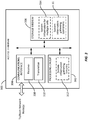
- FIG. 4 a block diagram is shown illustrating select components of a base station 400 according to at least one implementation.
- the base station 400 may include a processing circuit 402 coupled to a communications interface 404 and to a storage medium 406.
- the processing circuit 402 is arranged to obtain, process and/or send data, control data access and storage, issue commands, and control other desired operations.
- the processing circuit 402 may include circuitry configured to implement desired programming provided by appropriate media in at least one example, and may be implemented and/or adapted in a manner similar to the processing circuit 302 described above.
- the communications interface 404 is configured to facilitate wireless communications of the base station 400.
- the communications interface 404 may include circuitry and/or programming adapted to facilitate the communication of information with respect to one or more access terminals 300.
- the communications interface 404 may be coupled to one or more antennas (not shown), and includes wireless transceiver circuitry, including at least one receiver circuit 408 (e.g., one or more receiver chains) and/or at least one transmitter circuit 410 (e.g., one or more transmitter chains).
- the storage medium 406 may represent one or more devices for storing programming and/or data, such as processor executable code or instructions (e.g., software, firmware), electronic data, databases, or other digital information.
- the storage medium 406 may be configured and/or implemented in a manner similar to the storage medium 306 described above.
- the storage medium 406 includes programming stored thereon.
- the processing circuit 402 may be adapted to perform (in conjunction with the storage medium 406) any or all of the processes, functions, steps and/or routines for any or all of the network nodes described herein (e.g., base station 202 and/or base station controller 106 in FIG. 1 ).
- the term "adapted" in relation to the processing circuit 402 may refer to the processing circuit 402 being one or more of configured, employed, implemented, and/or programmed to perform a particular process, function, step and/or routine according to various features described herein.
- an access terminal is generally capable of retrieving system information from a base station in its vicinity.
- this system information may include active pilot information such as a cell ID, a latitude and longitude of the base station 400, pilot strength, etc.
- active pilot information such as a cell ID, a latitude and longitude of the base station 400, pilot strength, etc.
- system information for neighboring cells not currently serving the access terminal is generally unavailable. That is, because the derivation of this information would generally require the access terminal to detach from its current serving base station and attach to the neighboring base station, such information is not available to the conventional access terminal.
- some aspects of the present disclosure make suitable system information from neighboring cells available to the access terminal 300. This can assist and/or improve positioning of the access terminal 300 without substantially (or at all) affecting conventional communication protocols as well as making efficient use of power resources.
- a flow chart is provided to illustrate a process 500 of positioning a wireless access terminal such as the access terminal 300 illustrated in FIG. 3 within a wireless communication network in accordance with some aspects of the disclosure.
- the process 500 may operate at the access terminal 300 within the access network 100 illustrated in FIG. 1 , which as described above may be configured for operation according to cdma2000 1x standards.
- cdma2000 1x standards a wireless communication system
- the access terminal 300 may make a determination to find its position. In some examples, this determination may be made by the processing circuit 302 at the access terminal 300 in accordance with any suitable stimulus, such as a mapping application, a request from a user utilizing a user interface, etc. In other examples, this determination may be made by the access terminal 300 in response to the reception of a request from the network (e.g., transmitted by the base station 400) for the access terminal 300 to provide information from which the position may be determined.
- a mapping application e.g., a request from a user utilizing a user interface
- the access terminal may optionally transmit a request for position information. That is, in some aspects of the disclosure, the access terminal 300 may actively request position information from the network, such that the network can determine and transmit the location information to the access terminal 300 as described in further detail below. Of course, in other examples, wherein the access terminal 300 receives a request from the network to provide the system information for a plurality of base stations 400, the transmission of the request for position information at step 504 may be omitted.
- the access terminal 300 may establish communication with a first base station 400.
- the access terminal 300 may be turned on at this point, or the access terminal 300 may utilize mobility procedures to hand over from a neighbor cell to the first base station 400.
- the access terminal 300 may determine system information corresponding to the current serving cell, which at this time corresponds to the first base station 400. That is, when the access terminal 300 is served by a base station 400, the access terminal 300 can derive a list of parameters corresponding to that base station 400. For example, these parameters may include a cell identifier (cell_ID), a system ID (SID), and a network ID (NID).
- cell_ID cell identifier
- SID system ID
- NID network ID
- a globally unique identifier for a particular base cell is available.
- position information of the cell may be determined based on this cell identifier.
- these parameters may include a base station latitude, a base station longitude, a pilot strength, and/or a reference pseudorandom number (PN) used by the base station 400. Still further, these parameters may include the number of antennas utilized by the base station 400, whether the antennas are directional and which direction they transmit, etc. With the latitude and longitude associated with the base station 400 corresponding to that cell, and with the pilot strength and directionality of the pilot transmitted by that base station 400, additional position information can be determined.
- PN pseudorandom number
- the system information retrieved at step 508 may include an associated time stamp for recording the time at which the system information is retrieved.
- the clock is synchronized to GPS time. That is, an access terminal 300 configured for the CDMA system retrieves its time reference from the network, and the network synchronizes its time to the global positioning system (GPS).
- GPS global positioning system
- some aspects of the present disclosure may utilize a local clock at the access terminal 300 to obtain the associated time stamp.
- any suitable source for the time stamp may be utilized within the scope of the present disclosure.
- the access terminal 300 may store in memory (e.g., in the storage medium 306) the system information retrieved at step 508 from the current serving base station 400.
- the retrieved system information can be available to the access terminal 300 at a later time, e.g., when the first base station 400 is no longer serving the access terminal 300.
- system information corresponding to any suitable number of cells may be retained in the memory at any time.
- the access terminal 300 may store system information from a predetermined number of cells, or in other examples, the number of cells for which the system information is stored may be set by the access terminal 300 and/or the network in accordance with suitable factors.
- the access terminal 300 may determine whether system information corresponding to a sufficient number of cells has been gathered. If not, then the process may proceed to step 514, wherein the access terminal 300 may move to a second base station 400. For example, conventional mobility procedures may be utilized in accordance with movement of the access terminal 300 from one location to another. In another example, the access terminal may select another base station 400 to serve the access terminal 300 in accordance with any suitable handover procedure.
- the process may return to steps 508 and 510, determining the system information corresponding to the current serving cell and storing this retrieved system information in memory.
- This loop including the handover from cell to cell and the determining of system information for each cell in turn may proceed any suitable number of times, so that the access terminal 300 may accumulate the system information for a plurality of base stations 400 over time.
- an access network 600 is illustrated to show one example of an access terminal 300 moving through the access network 600 and accumulating system information for a plurality of base stations 400.
- the access terminal 300 first establishes communication with a first base station 400-A and according to an aspect of the present disclosure obtains and stores system information corresponding to the first base station 400-A.
- the access terminal 300 may utilize conventional mobility procedures to handover to a second base station 400-B.
- the access terminal 300 may obtain and store system information corresponding to the second base station 400-B.
- This procedure may repeat as the access terminal 300 continues to move about the access network 600, handing over to a third base station 400-C and a fourth base station 400-D.
- system information for the plurality of base stations 400-A to 400-D may be accumulated in memory at the access terminal 300 for use positioning the access terminal 300, as described below.
- the process may proceed to step 516, wherein the access terminal 300 may transmit the system information to the network.
- a software application may access the system information 314 for a plurality of cells stored in memory (e.g., at the storage medium 306) and in some examples may implement suitable processing on the system information.
- the application may send the system information (or information corresponding thereto) to a location server at the network for processing and determining position information corresponding to the access terminal 300. This determined position information may thereafter be transmitted to the access terminal, such that at step 518 the access terminal 300 may receive the position information.
- additional positioning information e.g., including but not limited to improved accuracy may be obtained when compared to positioning information obtainable only from the system information of the current serving cell.
- the utilization of time stamp information corresponding to the time when such system information was gathered for each of the plurality of cells can provide further enhancement of the position information obtainable therefrom.
- some aspects of the disclosure may provide information corresponding to a path of the access terminal 300 over time. For example, referring once again to FIG.
- the path taken by the access terminal 300 among these cells may be determined and accordingly relayed to the access terminal 300.
- a series of the most recently retrieved system information indicates little or no movement, it may be known that the access terminal 300 is stationary.
- the time stamp information may enable the position information may be adapted to additionally include velocity information corresponding to a velocity of the access terminal 300. That is, by determining the time difference between the obtaining of the system information of base stations 400 having known locations, a velocity of the access terminal 300 may be determined corresponding to its movement from cell to cell over time. Similarly, if the speed component of the velocity is unavailable or undesired, more simple direction information may be so obtained and transmitted to the access terminal 300.
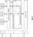
- FIG. 7 is a conceptual diagram providing additional details of one or more aspects of the disclosure.
- the access terminal 300 is shown in communication with a location framework 700.
- the location framework may be embodied by any suitable network entity such as a server configured for determining the position information in accordance with the system information provided by the access terminal 300.
- the access terminal 300 may reside certain functionality represented in the illustration by an upper layer 350 and a lower layer 360.
- the upper layer 350 may represent an application layer at the access terminal 300
- the lower layer 360 may represent the physical and/or MAC layers 202 and/or 206 described above in relation to FIG. 2 .
- the lower layer 360 at the access terminal 300 may search for pilot information, measure pilot strength, and perform other suitable lower-layer functions for gathering cell transmission information from one or more cells nearby the access terminal 300. That is, the lower layer 360 may generally concentrate on the pilot, e.g., seeking transmission characteristics such as the signal energy, without determining the higher-order system information such as the SID, the NID, etc.
- the lower layer 360 may include access to stored information corresponding to a set of pilots that have been acquired by the access terminal 300 over time. Here, if it is determined that an acquired pilot matches one of the stored set of pilots, parameters corresponding to the cell transmitting that pilot may be retrieved and sent up to the higher layer 350.
- the higher layer 350 may then retrieve the pilot information obtained by the lower layer 360 and access the SID/NID, cell_ID, latitude, longitude, etc. corresponding to the serving cell.
- the system information from the higher layer 350 and the lower layer 360 may be provided to the location framework 700, which may thereby determine current and past location of the access terminal 300, its direction and/or velocity, etc. as described above.
- FIGS. 1-7 One or more of the components, steps, features and/or functions illustrated in FIGS. 1-7 may be rearranged and/or combined into a single component, step, feature or function or embodied in several components, steps, or functions. Additional elements, components, steps, and/or functions may also be added without departing from the invention.
- the apparatus, devices and/or components illustrated in FIGS. 1 , 3 , 4 , 6 , and/or 7 may be configured to implement and/or perform one or more of the methods, features, or steps described in FIG. 5 .
- the novel algorithms described herein may also be efficiently implemented in software and/or embedded in hardware.
- a process is terminated when its operations are completed.
- a process may correspond to a method, a function, a procedure, a subroutine, a subprogram, etc.
- a process corresponds to a function
- its termination corresponds to a return of the function to the calling function or the main function.
- embodiments may be implemented by hardware, software, firmware, middleware, microcode, or any combination thereof.
- the program code or code segments to perform the necessary tasks may be stored in a machine-readable medium such as a storage medium or other storage(s).
- a processor may perform the necessary tasks.
- a code segment may represent a procedure, a function, a subprogram, a program, a routine, a subroutine, a module, a software package, a class, or any combination of instructions, data structures, or program statements.
- a code segment may be coupled to another code segment or a hardware circuit by passing and/or receiving information, data, arguments, parameters, or memory contents. Information, arguments, parameters, data, etc. may be passed, forwarded, or transmitted via any suitable means including memory sharing, message passing, token passing, network transmission, etc.
- machine-readable medium may include, but are not limited to portable or fixed storage devices, optical storage devices, and various other non-transitory mediums capable of storing, containing or carrying instruction(s) and/or data.
- machine-readable medium may include, but are not limited to portable or fixed storage devices, optical storage devices, and various other non-transitory mediums capable of storing, containing or carrying instruction(s) and/or data.
- various methods described herein may be partially or fully implemented by instructions and/or data that may be stored in a “machine-readable medium”, “computer-readable medium”, and/or “processor-readable medium” and executed by one or more processors, machines and/or devices.
- a software module may reside in RAM memory, flash memory, ROM memory, EPROM memory, EEPROM memory, registers, hard disk, a removable disk, a CD-ROM, or any other form of storage medium known in the art.
- a storage medium may be coupled to the processor such that the processor can read information from, and write information to, the storage medium. In the alternative, the storage medium may be integral to the processor.
Landscapes
- Engineering & Computer Science (AREA)
- Computer Networks & Wireless Communication (AREA)
- Signal Processing (AREA)
- Physics & Mathematics (AREA)
- General Physics & Mathematics (AREA)
- Radar, Positioning & Navigation (AREA)
- Remote Sensing (AREA)
- Mobile Radio Communication Systems (AREA)
- Position Fixing By Use Of Radio Waves (AREA)
- Telephonic Communication Services (AREA)
Description
- Embodiments of the present invention relate generally to wireless communication, and more specifically to methods and devices for determining a location and/or location information of a wireless access terminal.
- Wireless communications systems are widely deployed to provide various types of communication content such as voice, video, packet data, messaging, broadcast, and so on. These systems may be accessed by various types of access terminals adapted to facilitate wireless communications, where multiple access terminals share the available system resources (e.g., time, frequency, and power). Examples of such wireless communications systems include code-division multiple access (CDMA) systems, time- division multiple access (TDMA) systems, frequency-division multiple access (FDMA) systems and orthogonal frequency-division multiple access (OFDMA) systems.
- Mobile devices used in such wireless communication systems frequently include one or more means of determining their position. These can include but are not limited to the use of global positioning satellites (GPS) and trilateration techniques such as advanced forward link trilateration (AFLT). Each of these positioning techniques generally brings different advantages and disadvantages, providing different trade-offs of accuracy, battery consumption, availability in different areas, etc. The desire for always-available and highly accurate positioning information in concert with the least amount of battery consumption is always desired, and the development of positioning technologies has continued. Examples can be found in patent documents
WO2011/028452 andWO2007/001660 . Embodiments of the present invention are provisioned to address these issues as well as others - The following presents a simplified summary of one or more aspects of the present disclosure to provide a basic understanding of such aspects. This summary is not an extensive overview of all contemplated features of the disclosure, and is intended neither to identify key or critical elements of all aspects of the disclosure nor to delineate the scope of any or all aspects of the disclosure. Its sole purpose is to present some concepts of one or more aspects of the disclosure in a simplified form as a prelude to the more detailed description that is presented later.
- Various aspects of the disclosure provide for determining a position of an access terminal within a wireless communication network. In some examples, the access terminal retrieves system information from its current serving cell and stores the retrieved system information in memory along with an associated timestamp. Over time, as the access terminal moves about the network, it can accumulate system information for a plurality of base stations within its memory. By utilizing system information for a plurality of base stations rather than only the current serving base station, as well as the associated timestamps, additional position information can be provided to the access terminal.
- Other embodiments can also be directed to a communication apparatus. Such an apparatus can include a communications interface (e.g., receiver, transmitter, or transceiver). The communications interface can be operatively coupled to a processing module (or controller module). The apparatus can also include a memory coupled to the processing module. The processing module can be configured to obtain position information about the communication apparatus. This processing module can also be configured to analyze system information from multiple base stations (e.g., a first BS, a second BS, a current serving BS, and one or more prior serving BSs). By analyzing BS system information in concert with position information about the communication apparatus, the processing module can be used to localize the communications apparatus. This enables the communication apparatus to be always-available and have highly accurate positioning information in such a way to reduce processing to efficiently use power (e.g., battery) resources. The positioning information may then be passed on to applications that can use the positioning data as a user may desire or to other network components for their use.
- In one aspect, the disclosure provides a method of positioning a wireless access terminal, including determining to retrieve position information corresponding to the access terminal, determining system information corresponding to a current serving base station, storing the system information in a memory, storing an associated timestamp with the system information, and transmitting the system information and the associated timestamp for the current serving base station and for at least one prior serving base station, for localization of the access terminal.
- Another aspect of the disclosure provides an access terminal configured for wireless communication, including means for determining to retrieve position information corresponding to the access terminal, means for determining system information corresponding to a current serving base station, means for storing the system information, means for storing an associated timestamp with the system information, and means for transmitting the system information and the associated timestamp for the current serving base station and for at least one prior serving base station, for localization of the access terminal.
- Another aspect of the disclosure provides a computer program product including a computer-readable storage medium configured for operation at a wireless access terminal. Here, the computer-readable storage medium includes instructions for causing a computer to determine to retrieve position information corresponding to the access terminal, to determine system information corresponding to a current serving base station, to store the system information in a memory, to store an associated timestamp with the system information, and to transmit the system information and the associated timestamp for the current serving base station and for at least one prior serving base station, for localization of the access terminal.
- Another aspect of the disclosure provides an access terminal configured for wireless communication, including a processing circuit, a communications interface communicatively coupled to the processing circuit for transmitting and receiving information, and a memory communicatively coupled to the processing circuit for storing information, wherein the processing circuit is configured to determine to retrieve position information corresponding to the access terminal, to determine system information corresponding to a current serving base station, to store the system information in the memory, to store an associated timestamp with the system information, and to transmit the system information and the associated timestamp for the current serving base station and for at least one prior serving base station, for localization of the access terminal.
- These and other aspects of the invention will become more fully understood upon a review of the detailed description, which follows.
-
-
FIG. 1 is a block diagram illustrating an example of an access network in which one or more aspects of the present disclosure may find application. -
FIG. 2 is a block diagram illustrating an example of a protocol stack architecture which may be implemented for communication between an access terminal and a wireless communication network. -
FIG. 3 is a simplified block diagram illustrating some aspects of an access terminal according to one example. -
FIG. 4 is a simplified block diagram illustrating some aspects of a base station according to one example. -
FIG. 5 is a flow chart illustrating a process for determining a position of an access terminal according to one example. -
FIG. 6 is a conceptual diagram illustrating an access terminal moving about an access network and accumulating system information for a plurality of cells according to one example. -
FIG. 7 is a conceptual diagram illustrating additional details of an access terminal according to one example. - In the following description, specific details are given to provide a thorough understanding of the described implementations. However, it will be understood by one of ordinary skill in the art that at least some of the aspects described herein may be practiced without these specific details. For example, circuits may be shown in block diagrams in order not to obscure the implementations in unnecessary detail. In other instances, well-known circuits, structures, and techniques may be shown in detail in order not to obscure the implementations.
- In the following description, certain terminology is used to describe certain features of one or more implementations. The terms "access terminal" and "programming" as used herein are meant to be interpreted broadly. For example, an "access terminal" refers generally to one or more devices that communicate with one or more other devices through wireless signals. Such access terminals may also be referred to by those skilled in the art as a user equipment (UE), a mobile station (MS), a subscriber station, a mobile unit, a subscriber unit, a wireless unit, a remote unit, a mobile device, a wireless device, a wireless communications device, a remote device, a mobile subscriber station, a mobile terminal, a wireless terminal, a remote terminal, a handset, a terminal, a user agent, a mobile client, a client, or some other suitable terminology. Access terminals may include mobile terminals, at least substantially fixed terminals, and/or stationary communication components. Examples of access terminals include mobile phones, pagers, wireless modems, personal digital assistants, personal information managers (PIMs), personal media players, palmtop computers, laptop computers, tablet computers, televisions, appliances, e-readers, digital video recorders (DVRs), machine-to-machine (M2M) devices, routers, smartphones, entertainment devices, and/or other communication/computing devices which communicate, at least partially, through a wireless or cellular network.
- The term "programming" shall be construed broadly to include without limitation instructions, instruction sets, code, code segments, program code, programs, subprograms, software modules, applications, software applications, software packages, routines, subroutines, objects, executables, threads of execution, procedures, functions, etc., whether referred to as software, firmware, middleware, microcode, hardware description language, or otherwise.
- The various concepts presented throughout this disclosure may be implemented across a broad variety of telecommunication systems, network architectures, and communication standards. Although the discussions herein may present examples of CDMA and 3rd Generation Partnership Project 2 (3GPP2) 1x protocols and systems, those of ordinary skill in the art will recognize that one or more aspects of the present disclosure may be employed and included in one or more other wireless communication protocols and systems.
-
FIG. 1 is a conceptual diagram illustrating an example of a network environment in which one or more aspects of the present disclosure may find application. Thewireless communication system 100 generally includes one ormore base stations 102, one ormore access terminals 104, one or more base station controllers (BSC) 106, and acore network 108 providing access to a public switched telephone network (PSTN) (e.g., via a mobile switching center/visitor location register (MSC/VLR)) and/or to an IP network (e.g., via a packet data switching node (PDSN)). Thesystem 100 may support operation on multiple carriers (waveform signals of different frequencies). Multi-carrier transmitters can transmit modulated signals simultaneously on the multiple carriers. Each modulated signal may be a CDMA signal, a TDMA signal, an OFDMA signal, a Single Carrier Frequency Division Multiple Access (SC-FDMA) signal, etc. Each modulated signal may be sent on a different carrier and may carry control information (e.g., pilot signals), overhead information, data, etc. - The
base stations 102 may wirelessly communicate with theaccess terminals 104 via a base station antenna. Thebase stations 102 may each include a device that facilitates wireless connectivity (for one or more access terminals 104) to thewireless communications system 100. For example, thebase stations 102 may include access points, base transceiver stations (BTS), radio base stations, radio transceivers, transceiver functions, basic service sets (BSS), extended service sets (ESS), Node Bs, femto cells, pico cells, and/or some other suitable device. - The
base stations 102 are configured to communicate with theaccess terminals 104 under the control of thebase station controller 106 via multiple carriers. Each of thebase stations 102 can provide communication coverage for a respective geographic area. Thecoverage area 110 for eachbase station 102 here is identified as cells 110-a, 110-b, or 110-c. Thecoverage area 110 for abase station 102 may be divided into sectors (not shown, but making up only a portion of the coverage area). In acoverage area 110 that is divided into sectors, the multiple sectors within acoverage area 110 can be formed by groups of antennas with each antenna responsible for communication with one ormore access terminals 104 in a portion of the cell. - The
access terminals 104 may be dispersed throughout thecoverage areas 110, and may wirelessly communicate with one or more sectors associated with eachrespective base station 102. Theaccess terminal 104 may be adapted to employ a protocol stack architecture for communicating data between theaccess terminal 104 and one or more network nodes of the wireless communication system 100 (e.g., the base station 102). - A protocol stack generally includes a conceptual model of the layered architecture for communication protocols. The layers are represented in order of their numeric designation, where transferred data is processed sequentially by each layer, in the order of their representation. Graphically, the "stack" is typically shown vertically, with the layer having the lowest numeric designation at the base.
-
FIG. 2 is a block diagram illustrating an example of a protocol stack architecture which may be implemented by anaccess terminal 104. Referring toFIGS. 1 and2 , the protocol stack architecture for theaccess terminal 104 is shown with three layers: Layer 1 (L1), Layer 2 (L2), and Layer 3 (L3). - Layer 1 202 is the lowest layer and implements various physical layer signal processing functions. Layer 1 202 is also referred to herein as the
physical layer 202. Thisphysical layer 202 provides for the transmission and reception of radio signals between theaccess terminal 104 and abase station 102. - The data link layer, called layer 2 (or "the L2 layer") 204 is above the
physical layer 202 and is responsible for delivery of signaling messages generated by Layer 3. TheL2 layer 204 makes use of the services provided by thephysical layer 202. TheL2 layer 204 may include two sublayers: the Medium Access Control (MAC)sublayer 206, and the Link Access Control (LAC)sublayer 208. - The
MAC sublayer 206 is the lower sublayer of theL2 layer 204. TheMAC sublayer 206 implements the medium access protocol and is responsible for transport of higher layers' protocol data units using the services provided by thephysical layer 202. TheMAC sublayer 206 may manage the access of data from the higher layers to the shared air interface. - The
LAC sublayer 208 is the upper sublayer of theL2 layer 204. TheLAC sublayer 208 implements a data link protocol that provides for the correct transport and delivery of signaling messages generated at the layer 3. The LAC sublayer makes use of the services provided by the lower layers (e.g., layer 1 and the MAC sublayer). - Layer 3 210, which may also be referred to as the upper layer or the L3 layer, originates and terminates signaling messages according to the semantics and timing of the communication protocol between a
base station 102 and theaccess terminal 104. TheL3 layer 210 makes use of the services provided by the L2 layer. Information (both data and voice) message are also passed through theL3 layer 210. -
FIG. 3 is a block diagram illustrating select components of anaccess terminal 300 adapted to employ such features according to at least one example. Theaccess terminal 300 may include aprocessing circuit 302 coupled to acommunications interface 304 and to astorage medium 306. - The
processing circuit 302 is arranged to obtain, process and/or send data, control data access and storage, issue commands, and control other desired operations. Theprocessing circuit 302 may include circuitry configured to implement desired programming provided by appropriate media in at least one embodiment. For example, theprocessing circuit 302 may be implemented as one or more of a processor, a controller, a plurality of processors and/or other structure configured to execute executable instructions including, for example, software and/or firmware instructions, and/or hardware circuitry. Examples of theprocessing circuit 302 may include a general purpose processor, a digital signal processor (DSP), an application specific integrated circuit (ASIC), a field programmable gate array (FPGA) or other programmable logic component, discrete gate or transistor logic, discrete hardware components, or any combination thereof designed to perform the functions described herein. A general purpose processor may be a microprocessor but, in the alternative, the processor may be any conventional processor, controller, microcontroller, or state machine. A processor may also be implemented as a combination of computing components, such as a combination of a DSP and a microprocessor, a number of microprocessors, one or more microprocessors in conjunction with a DSP core, or any other such configuration. These examples of theprocessing circuit 302 are for illustration and other suitable configurations within the scope of the present disclosure are also contemplated. - The
processing circuit 302 is adapted for processing, including the execution of programming, which may be stored on thestorage medium 306. In some instances, theprocessing circuit 302 may include systeminformation gathering circuitry 312. The systeminformation gathering circuitry 312 may include circuitry and/or programming adapted to utilize thetransmitter 310 and/or thereceiver 308 to retrieve system information corresponding to one or more base stations, for the positioning of theaccess terminal 300. - The
communications interface 304 is configured to facilitate wireless communications of theaccess terminal 300. For example, thecommunications interface 304 may include circuitry and/or programming adapted to facilitate the communication of information bi-directionally with respect to one or more network nodes. Thecommunications interface 304 may be coupled to one or more antennas (not shown), and includes wireless transceiver circuitry, including at least one receiver circuit 308 (e.g., one or more receiver chains) and/or at least one transmitter circuit 310 (e.g., one or more transmitter chains). By way of example and not limitation, the at least onetransmitter circuit 310 may include circuitry, devices and/or programming adapted to provide various signal conditioning functions including amplification, filtering, and modulating transmission frames onto a carrier for uplink transmission over a wireless medium through an antenna. - The
storage medium 306 may represent one or more devices for storing programming and/or data, such as processor executable code or instructions (e.g., software, firmware), electronic data, databases, or other digital information. Thestorage medium 306 may also be used for storing data that is manipulated by theprocessing circuit 302 when executing programming. Thestorage medium 306 may be any available media that can be accessed by a general purpose or special purpose processor. By way of example and not limitation, thestorage medium 306 may include a non-transitory computer-readable medium such as a magnetic storage device (e.g., hard disk, floppy disk, magnetic strip), an optical storage medium (e.g., compact disk (CD), digital versatile disk (DVD)), a smart card, a flash memory device (e.g., card, stick, key drive), random access memory (RAM), read only memory (ROM), programmable ROM (PROM), erasable PROM (EPROM), electrically erasable PROM (EEPROM), a register, a removable disk, and/or other non-transitory computer-readable mediums for storing information, as well as any combination thereof. Thestorage medium 306 may be coupled to, or at least accessible by theprocessing circuit 302 such that theprocessing circuit 302 can read information from, and write information to, thestorage medium 306. In the examples, thestorage medium 306 may be integral to theprocessing circuit 302. But in some embodiments these components may be distinct devices. - Programming stored by the
storage medium 306, when executed by theprocessing circuit 302, causes theprocessing circuit 302 to perform one or more of the various functions and/or process steps described herein. Thestorage medium 306 may system information gathering operations (i.e., instructions) 314. The transmitterpower regulating operations 314 can be implemented by theprocessing circuit 302 in, for example, thetransmitter power regulator 312. Thus, according to one or more aspects of the present disclosure, theprocessing circuit 302 may be adapted to perform any or all of the processes, functions, steps and/or routines for any or all of the access terminals (e.g.,access terminal 104 or 300) described herein. As used herein, the term "adapted" in relation to theprocessing circuit 302 may refer to theprocessing circuit 302 being one or more of configured, employed, implemented, or programmed to perform a particular process, function, step and/or routine according to various features described herein. - According to various further aspects of the present disclosure, base stations are provided, which are adapted to transmit pilot signals and to provide various system information to access terminals in their vicinity. Turning to
FIG. 4 , a block diagram is shown illustrating select components of abase station 400 according to at least one implementation. Thebase station 400 may include aprocessing circuit 402 coupled to acommunications interface 404 and to astorage medium 406. - The
processing circuit 402 is arranged to obtain, process and/or send data, control data access and storage, issue commands, and control other desired operations. Theprocessing circuit 402 may include circuitry configured to implement desired programming provided by appropriate media in at least one example, and may be implemented and/or adapted in a manner similar to theprocessing circuit 302 described above. - The
communications interface 404 is configured to facilitate wireless communications of thebase station 400. For example, thecommunications interface 404 may include circuitry and/or programming adapted to facilitate the communication of information with respect to one ormore access terminals 300. Thecommunications interface 404 may be coupled to one or more antennas (not shown), and includes wireless transceiver circuitry, including at least one receiver circuit 408 (e.g., one or more receiver chains) and/or at least one transmitter circuit 410 (e.g., one or more transmitter chains). - The
storage medium 406 may represent one or more devices for storing programming and/or data, such as processor executable code or instructions (e.g., software, firmware), electronic data, databases, or other digital information. Thestorage medium 406 may be configured and/or implemented in a manner similar to thestorage medium 306 described above. - Like the
storage medium 306, thestorage medium 406 includes programming stored thereon. The programming stored by thestorage medium 406, when executed by theprocessing circuit 402, causes theprocessing circuit 402 to perform one or more of the various functions and/or process steps described herein. Thus, according to one or more aspects of the present disclosure, theprocessing circuit 402 may be adapted to perform (in conjunction with the storage medium 406) any or all of the processes, functions, steps and/or routines for any or all of the network nodes described herein (e.g.,base station 202 and/orbase station controller 106 inFIG. 1 ). As used herein, the term "adapted" in relation to theprocessing circuit 402 may refer to theprocessing circuit 402 being one or more of configured, employed, implemented, and/or programmed to perform a particular process, function, step and/or routine according to various features described herein. - In a cdma2000 1x system, an access terminal is generally capable of retrieving system information from a base station in its vicinity. For example, this system information may include active pilot information such as a cell ID, a latitude and longitude of the
base station 400, pilot strength, etc. However, in conventional systems, such system information for neighboring cells not currently serving the access terminal is generally unavailable. That is, because the derivation of this information would generally require the access terminal to detach from its current serving base station and attach to the neighboring base station, such information is not available to the conventional access terminal. Thus, some aspects of the present disclosure make suitable system information from neighboring cells available to theaccess terminal 300. This can assist and/or improve positioning of theaccess terminal 300 without substantially (or at all) affecting conventional communication protocols as well as making efficient use of power resources. - Referring now to
FIG. 5 , a flow chart is provided to illustrate aprocess 500 of positioning a wireless access terminal such as theaccess terminal 300 illustrated inFIG. 3 within a wireless communication network in accordance with some aspects of the disclosure. In some examples, theprocess 500 may operate at theaccess terminal 300 within theaccess network 100 illustrated inFIG. 1 , which as described above may be configured for operation according to cdma2000 1x standards. Of course, those of ordinary skill in the art will comprehend that any suitable wireless communication system may be utilized within the scope of the present disclosure. - At
step 502, theaccess terminal 300 may make a determination to find its position. In some examples, this determination may be made by theprocessing circuit 302 at theaccess terminal 300 in accordance with any suitable stimulus, such as a mapping application, a request from a user utilizing a user interface, etc. In other examples, this determination may be made by theaccess terminal 300 in response to the reception of a request from the network (e.g., transmitted by the base station 400) for theaccess terminal 300 to provide information from which the position may be determined. - At
step 504, the access terminal may optionally transmit a request for position information. That is, in some aspects of the disclosure, theaccess terminal 300 may actively request position information from the network, such that the network can determine and transmit the location information to theaccess terminal 300 as described in further detail below. Of course, in other examples, wherein theaccess terminal 300 receives a request from the network to provide the system information for a plurality ofbase stations 400, the transmission of the request for position information atstep 504 may be omitted. - At
step 506, theaccess terminal 300 may establish communication with afirst base station 400. For example, theaccess terminal 300 may be turned on at this point, or theaccess terminal 300 may utilize mobility procedures to hand over from a neighbor cell to thefirst base station 400. - At
step 508, theaccess terminal 300 may determine system information corresponding to the current serving cell, which at this time corresponds to thefirst base station 400. That is, when theaccess terminal 300 is served by abase station 400, theaccess terminal 300 can derive a list of parameters corresponding to thatbase station 400. For example, these parameters may include a cell identifier (cell_ID), a system ID (SID), and a network ID (NID). Here, with the combination of the SID, NID, and cell_ID, a globally unique identifier for a particular base cell is available. With a suitable database storing cell service locations, position information of the cell may be determined based on this cell identifier. Furthermore, these parameters may include a base station latitude, a base station longitude, a pilot strength, and/or a reference pseudorandom number (PN) used by thebase station 400. Still further, these parameters may include the number of antennas utilized by thebase station 400, whether the antennas are directional and which direction they transmit, etc. With the latitude and longitude associated with thebase station 400 corresponding to that cell, and with the pilot strength and directionality of the pilot transmitted by thatbase station 400, additional position information can be determined. - Still further, the system information retrieved at
step 508 may include an associated time stamp for recording the time at which the system information is retrieved. In a CDMA system, the clock is synchronized to GPS time. That is, anaccess terminal 300 configured for the CDMA system retrieves its time reference from the network, and the network synchronizes its time to the global positioning system (GPS). In another example, some aspects of the present disclosure may utilize a local clock at theaccess terminal 300 to obtain the associated time stamp. Of course, any suitable source for the time stamp may be utilized within the scope of the present disclosure. - At
step 510, theaccess terminal 300 may store in memory (e.g., in the storage medium 306) the system information retrieved atstep 508 from the currentserving base station 400. In this way, in accordance with an aspect of the disclosure, the retrieved system information can be available to theaccess terminal 300 at a later time, e.g., when thefirst base station 400 is no longer serving theaccess terminal 300. - In various examples, system information corresponding to any suitable number of cells may be retained in the memory at any time. For example, the
access terminal 300 may store system information from a predetermined number of cells, or in other examples, the number of cells for which the system information is stored may be set by theaccess terminal 300 and/or the network in accordance with suitable factors. - At
step 512, theaccess terminal 300 may determine whether system information corresponding to a sufficient number of cells has been gathered. If not, then the process may proceed to step 514, wherein theaccess terminal 300 may move to asecond base station 400. For example, conventional mobility procedures may be utilized in accordance with movement of theaccess terminal 300 from one location to another. In another example, the access terminal may select anotherbase station 400 to serve theaccess terminal 300 in accordance with any suitable handover procedure. - Following the handover to the second base station at
step 514, the process may return tosteps access terminal 300 may accumulate the system information for a plurality ofbase stations 400 over time. - Referring now to
FIG. 6 , a portion of anaccess network 600 is illustrated to show one example of anaccess terminal 300 moving through theaccess network 600 and accumulating system information for a plurality ofbase stations 400. As seen in this example, theaccess terminal 300 first establishes communication with a first base station 400-A and according to an aspect of the present disclosure obtains and stores system information corresponding to the first base station 400-A. As theaccess terminal 300 thereafter moves in a northward direction on the illustration, it may utilize conventional mobility procedures to handover to a second base station 400-B. At this time, as described above, theaccess terminal 300 may obtain and store system information corresponding to the second base station 400-B. This procedure may repeat as theaccess terminal 300 continues to move about theaccess network 600, handing over to a third base station 400-C and a fourth base station 400-D. Thereby, system information for the plurality of base stations 400-A to 400-D may be accumulated in memory at theaccess terminal 300 for use positioning theaccess terminal 300, as described below. - Returning now to
FIG. 5 , if atstep 512 theaccess terminal 300 determines that sufficient system information has been gathered for the plurality of cells, the process may proceed to step 516, wherein theaccess terminal 300 may transmit the system information to the network. For example, a software application may access thesystem information 314 for a plurality of cells stored in memory (e.g., at the storage medium 306) and in some examples may implement suitable processing on the system information. Upon processing (if any), the application may send the system information (or information corresponding thereto) to a location server at the network for processing and determining position information corresponding to theaccess terminal 300. This determined position information may thereafter be transmitted to the access terminal, such that atstep 518 theaccess terminal 300 may receive the position information. - By utilizing the system information corresponding to a plurality of cells as described above, additional positioning information, e.g., including but not limited to improved accuracy may be obtained when compared to positioning information obtainable only from the system information of the current serving cell. Moreover, as described above, the utilization of time stamp information corresponding to the time when such system information was gathered for each of the plurality of cells can provide further enhancement of the position information obtainable therefrom. For example, some aspects of the disclosure may provide information corresponding to a path of the
access terminal 300 over time. For example, referring once again toFIG. 6 , by considering time stamps corresponding to the time when system information was obtained from each of the four base stations 400-A, 400-B, 400-C, and 400-D, the path taken by theaccess terminal 300 among these cells may be determined and accordingly relayed to theaccess terminal 300. Similarly, if a series of the most recently retrieved system information indicates little or no movement, it may be known that theaccess terminal 300 is stationary. - Still further, the time stamp information may enable the position information may be adapted to additionally include velocity information corresponding to a velocity of the
access terminal 300. That is, by determining the time difference between the obtaining of the system information ofbase stations 400 having known locations, a velocity of theaccess terminal 300 may be determined corresponding to its movement from cell to cell over time. Similarly, if the speed component of the velocity is unavailable or undesired, more simple direction information may be so obtained and transmitted to theaccess terminal 300. -
FIG. 7 is a conceptual diagram providing additional details of one or more aspects of the disclosure. In the illustration, theaccess terminal 300 is shown in communication with alocation framework 700. In various examples, the location framework may be embodied by any suitable network entity such as a server configured for determining the position information in accordance with the system information provided by theaccess terminal 300. - Within the
access terminal 300 may reside certain functionality represented in the illustration by anupper layer 350 and alower layer 360. Here, theupper layer 350 may represent an application layer at theaccess terminal 300, and thelower layer 360 may represent the physical and/orMAC layers 202 and/or 206 described above in relation toFIG. 2 . - In an aspect of the disclosure, the
lower layer 360 at theaccess terminal 300 may search for pilot information, measure pilot strength, and perform other suitable lower-layer functions for gathering cell transmission information from one or more cells nearby theaccess terminal 300. That is, thelower layer 360 may generally concentrate on the pilot, e.g., seeking transmission characteristics such as the signal energy, without determining the higher-order system information such as the SID, the NID, etc. In some aspects of the disclosure, thelower layer 360 may include access to stored information corresponding to a set of pilots that have been acquired by theaccess terminal 300 over time. Here, if it is determined that an acquired pilot matches one of the stored set of pilots, parameters corresponding to the cell transmitting that pilot may be retrieved and sent up to thehigher layer 350. - The
higher layer 350 may then retrieve the pilot information obtained by thelower layer 360 and access the SID/NID, cell_ID, latitude, longitude, etc. corresponding to the serving cell. Thus, in conjunction, the system information from thehigher layer 350 and thelower layer 360 may be provided to thelocation framework 700, which may thereby determine current and past location of theaccess terminal 300, its direction and/or velocity, etc. as described above. - One or more of the components, steps, features and/or functions illustrated in
FIGS. 1-7 may be rearranged and/or combined into a single component, step, feature or function or embodied in several components, steps, or functions. Additional elements, components, steps, and/or functions may also be added without departing from the invention. The apparatus, devices and/or components illustrated inFIGS. 1 ,3 ,4 ,6 , and/or 7 may be configured to implement and/or perform one or more of the methods, features, or steps described inFIG. 5 . The novel algorithms described herein may also be efficiently implemented in software and/or embedded in hardware. - Also, it is noted that at least some implementations have been described as a process that is depicted as a flowchart, a flow diagram, a structure diagram, or a block diagram. Although a flowchart may describe the operations as a sequential process, many of the operations can be performed in parallel or concurrently. In addition, the order of the operations may be re-arranged. A process is terminated when its operations are completed. A process may correspond to a method, a function, a procedure, a subroutine, a subprogram, etc. When a process corresponds to a function, its termination corresponds to a return of the function to the calling function or the main function.
- Moreover, embodiments may be implemented by hardware, software, firmware, middleware, microcode, or any combination thereof. When implemented in software, firmware, middleware or microcode, the program code or code segments to perform the necessary tasks may be stored in a machine-readable medium such as a storage medium or other storage(s). A processor may perform the necessary tasks. A code segment may represent a procedure, a function, a subprogram, a program, a routine, a subroutine, a module, a software package, a class, or any combination of instructions, data structures, or program statements. A code segment may be coupled to another code segment or a hardware circuit by passing and/or receiving information, data, arguments, parameters, or memory contents. Information, arguments, parameters, data, etc. may be passed, forwarded, or transmitted via any suitable means including memory sharing, message passing, token passing, network transmission, etc.
- The terms "machine-readable medium", "computer-readable medium", and/or "processor-readable medium" may include, but are not limited to portable or fixed storage devices, optical storage devices, and various other non-transitory mediums capable of storing, containing or carrying instruction(s) and/or data. Thus, the various methods described herein may be partially or fully implemented by instructions and/or data that may be stored in a "machine-readable medium", "computer-readable medium", and/or "processor-readable medium" and executed by one or more processors, machines and/or devices.
- The methods or algorithms described in connection with the examples disclosed herein may be embodied directly in hardware, in a software module executable by a processor, or in a combination of both, in the form of processing unit, programming instructions, or other directions, and may be contained in a single device or distributed across multiple devices. A software module may reside in RAM memory, flash memory, ROM memory, EPROM memory, EEPROM memory, registers, hard disk, a removable disk, a CD-ROM, or any other form of storage medium known in the art. A storage medium may be coupled to the processor such that the processor can read information from, and write information to, the storage medium. In the alternative, the storage medium may be integral to the processor.
- Those of skill in the art would further appreciate that the various illustrative logical blocks, modules, circuits, and algorithm steps described in connection with the embodiments disclosed herein may be implemented as electronic hardware, computer software, or combinations of both. To clearly illustrate this interchangeability of hardware and software, various illustrative components, blocks, modules, circuits, and steps have been described above generally in terms of their functionality. Whether such functionality is implemented as hardware or software depends upon the particular application and design constraints imposed on the overall system.
- The various features of the invention described herein can be implemented in different systems without departing from the invention. It should be noted that the foregoing embodiments are merely examples and are not to be construed as limiting the invention. The description of the embodiments is intended to be illustrative, and not to limit the scope of the claims. As such, the present teachings can be readily applied to other types of apparatuses and many alternatives, modifications, and variations will be apparent to those skilled in the art.
Claims (11)
- A method (500) operational on a wireless access terminal (104,300), of positioning the wireless access terminal (104,300), comprising:determining if to retrieve position information corresponding to the access terminal; and in response to the determination:determining (508) system information corresponding to each of a plurality of serving base stations (400) of a network (600), wherein the system information comprising latitude and longitude associated with each base station (400) of the plurality of base stations;storing (510) the determined system information associated with each of the plurality of base stations as accumulated system information over time in a memory (306) of the wireless access terminal; andstoring (510) for each of the plurality of base stations an associated timestamp with the system information; anddetermining (512) if sufficient system information corresponding to a sufficient number of base stations (400) has been gathered and in response to the determination (512)transmitting (516) the accumulated system information and time stamps for the current serving base station and for at least one prior serving base station, for localization of the access terminal, wherein the associated timestamp is adapted to record the time at which the system information is determined and wherein the accumulated system information and time stamps are accumulated over time as the access terminal moves about the network (600).
- The method of claim 1, further comprising:handing (514) over to a second serving base station (400);determining (508) second system information corresponding to the second serving base station (400), wherein the second system information comprises at least one of a second base station latitude and/or a second base station longitude;storing (510) the second system information in the memory (306); andstoring (510) a second associated timestamp with the second system information,wherein the transmitting (516) of the system information and the associated timestamp further comprises transmitting the second system information and the second timestamp for localization of the access terminal (104,300).
- The method of claim 1, further comprising receiving position information (518) in response to the transmitting of the system information, the position information corresponding at least in part to a position of the access terminal (104,300).
- The method of claim 3, wherein the position information comprises at least one of speed, direction, and/or velocity information corresponding to the access terminal (104,300).
- The method of claim 3, wherein the position information comprises a path that the access terminal (104,300) has taken.
- The method of claim 1, wherein the determining of the system information comprises deriving a set of parameters corresponding to the serving base station (400) in accordance with a pilot received from the serving base station and stored information corresponding to a set of pilots that have previously been acquired by the access terminal (104,300).
- An access terminal configured for wireless communication, comprising:means for determining if to retrieve position information corresponding to the access terminal (104,300);means for determining system information corresponding to each of a plurality of base stations (400) of a network (600), wherein the system information comprises latitude and longitude associated with each base station of the plurality of base stations;means for storing the determined system information associated with each of the plurality of base stations as accumulated system information over time in a memory of the access terminal; andmeans for storing an associated timestamp with the system information;means for determining (512) if sufficient system information corresponding to a sufficient number of base stations (400) has been gathered and in response to the determination (512) using transmitting means for transmitting the accumulated system information and the associated timestamp for the current serving base station and for at least one prior serving base station, for localization of the access terminal (104,300) wherein the associated timestamp is adapted to record the time at which the system information is determined and wherein the accumulated system information and time stamps are accumulated over time as the access terminal moves about the network (600).
- The access terminal (104,300), of claim 7, further comprising:means for handing over to a second serving base station;means for determining second system information corresponding to the second serving base station, wherein the second system information comprises at least one of a second base station latitude and/or a second base station longitude;means for storing the second system information; andmeans for storing a second associated timestamp with the second system information;wherein the means for transmitting the system information and the associated timestamp is further configured to transmit the second system information and the second timestamp for localization of the access terminal.
- The access terminal (104,300), of claim 7, further comprising means for receiving position information in response to the transmitting of the system information, the position information corresponding at least in part to a position of the access terminal.
- The access terminal (104,300) of claim 7, wherein the means for determining the system information is configured to derive a set of parameters corresponding to the serving base station in accordance with a pilot received from the serving base station and stored information corresponding to a set of pilots that have previously been acquired by the access terminal.
- A computer program product comprising:
a computer-readable storage medium configured for operation at a wireless access terminal, comprising instructions for causing a computer to implement the method accordingly to any of claims 1 to 6.
Applications Claiming Priority (3)
| Application Number | Priority Date | Filing Date | Title |
|---|---|---|---|
| US201261592770P | 2012-01-31 | 2012-01-31 | |
| US13/599,448 US9071936B2 (en) | 2012-01-31 | 2012-08-30 | Methods and devices for facilitating location approximation in a CDMA 1x network |
| PCT/US2013/022243 WO2013116015A1 (en) | 2012-01-31 | 2013-01-18 | Methods and devices for facilitating location approximation in a cdma 1x network |
Publications (2)
| Publication Number | Publication Date |
|---|---|
| EP2810504A1 EP2810504A1 (en) | 2014-12-10 |
| EP2810504B1 true EP2810504B1 (en) | 2019-11-06 |
Family
ID=47630587
Family Applications (1)
| Application Number | Title | Priority Date | Filing Date |
|---|---|---|---|
| EP13702174.7A Active EP2810504B1 (en) | 2012-01-31 | 2013-01-18 | Method and device for facilitating location approximation in a cdma 1x network |
Country Status (7)
| Country | Link |
|---|---|
| US (1) | US9071936B2 (en) |
| EP (1) | EP2810504B1 (en) |
| JP (2) | JP6250558B2 (en) |
| KR (1) | KR20140124383A (en) |
| CN (1) | CN104106293B (en) |
| IN (1) | IN2014CN04850A (en) |
| WO (1) | WO2013116015A1 (en) |
Families Citing this family (9)
| Publication number | Priority date | Publication date | Assignee | Title |
|---|---|---|---|---|
| US8849306B1 (en) * | 2013-01-30 | 2014-09-30 | Sprint Spectrum L.P. | Management of base station connectivity in location based service requests |
| CN104821956B (en) * | 2015-03-31 | 2019-01-18 | 百度在线网络技术(北京)有限公司 | Localization method and device based on electronic equipment or application |
| WO2016191955A1 (en) * | 2015-05-29 | 2016-12-08 | 华为技术有限公司 | System information acquisition method in cell cluster, relevant device and system |
| KR101631121B1 (en) * | 2015-08-18 | 2016-06-27 | 주식회사 아이쉐어링소프트 | Method of measuring a location of mobile computing device and mobile computing device performing the same |
| WO2018023700A1 (en) * | 2016-08-05 | 2018-02-08 | Honeywell International Inc. | System including base stations that provide information from which a mobile station can determine its position |
| EP4096263B1 (en) * | 2016-10-07 | 2023-09-06 | FG Innovation Company Limited | Method and apparatus for system information delivery |
| EP3556144A1 (en) * | 2016-12-16 | 2019-10-23 | Telefonaktiebolaget LM Ericsson (PUBL) | Wireless device, network node, and methods and computer programs for the same |
| GB2567296B (en) * | 2017-08-09 | 2021-08-25 | Samsung Electronics Co Ltd | System and method for transmitting and receiving system information |
| CN108449793B (en) * | 2018-05-17 | 2024-05-10 | 成都四相致新科技有限公司 | One-dimensional positioning base station and positioning method |
Citations (1)
| Publication number | Priority date | Publication date | Assignee | Title |
|---|---|---|---|---|
| WO2007001660A2 (en) * | 2005-06-28 | 2007-01-04 | Microsoft Corporation | Positioning service utilizing existing radio base stations |
Family Cites Families (13)
| Publication number | Priority date | Publication date | Assignee | Title |
|---|---|---|---|---|
| US6393294B1 (en) | 1998-09-22 | 2002-05-21 | Polaris Wireless, Inc. | Location determination using RF fingerprinting |
| FI114192B (en) | 2003-03-24 | 2004-08-31 | Elisa Matkapuhelinpalvelut Oy | Anonymous cellular mobile subscriber detection |
| JP2007133828A (en) * | 2005-11-14 | 2007-05-31 | Hitachi Ltd | Traffic information generating device, and method and program for specifying vehicle position information |
| US8606299B2 (en) | 2006-01-09 | 2013-12-10 | Qualcomm Incorporated | Apparatus and methods for geographic position approximation of an event occurring on a wireless device |
| JP2007214801A (en) * | 2006-02-08 | 2007-08-23 | Fuji Electric Holdings Co Ltd | Operator authentication management system |
| US8798639B2 (en) | 2007-01-17 | 2014-08-05 | Qualcomm Incorporated | Method and apparatus for using historic network information for determining approximate position |
| JP5038793B2 (en) * | 2007-06-27 | 2012-10-03 | 株式会社エヌ・ティ・ティ・ドコモ | Position estimation system |
| US20090088180A1 (en) * | 2007-10-01 | 2009-04-02 | James Lamance | Computing geographical location of a mobile receiver using network measurement reports |
| US20100093376A1 (en) | 2008-10-14 | 2010-04-15 | Del Castillo Manuel | Method and system for area code rough initial position for gnss assistance data in a communication network |
| EP2199818B1 (en) | 2008-12-19 | 2019-02-20 | Koninklijke KPN N.V. | Method of determining a location of a mobile device |
| US8611326B2 (en) * | 2009-09-03 | 2013-12-17 | Apple Inc. | Location histories for location aware devices |
| JP2011077896A (en) * | 2009-09-30 | 2011-04-14 | Ntt Docomo Inc | Method of providing positional information service, switching station and server device |
| US9037163B2 (en) * | 2009-10-09 | 2015-05-19 | Qualcomm Incorporated | Method and apparatus for continuity of positioning determination at handover |
-
2012
- 2012-08-30 US US13/599,448 patent/US9071936B2/en active Active
-
2013
- 2013-01-18 WO PCT/US2013/022243 patent/WO2013116015A1/en active Application Filing
- 2013-01-18 CN CN201380007109.1A patent/CN104106293B/en active Active
- 2013-01-18 KR KR20147023712A patent/KR20140124383A/en not_active Application Discontinuation
- 2013-01-18 JP JP2014554749A patent/JP6250558B2/en not_active Expired - Fee Related
- 2013-01-18 IN IN4850CHN2014 patent/IN2014CN04850A/en unknown
- 2013-01-18 EP EP13702174.7A patent/EP2810504B1/en active Active
-
2017
- 2017-09-21 JP JP2017181351A patent/JP2018029351A/en active Pending
Patent Citations (1)
| Publication number | Priority date | Publication date | Assignee | Title |
|---|---|---|---|---|
| WO2007001660A2 (en) * | 2005-06-28 | 2007-01-04 | Microsoft Corporation | Positioning service utilizing existing radio base stations |
Also Published As
| Publication number | Publication date |
|---|---|
| KR20140124383A (en) | 2014-10-24 |
| JP6250558B2 (en) | 2017-12-20 |
| US9071936B2 (en) | 2015-06-30 |
| JP2018029351A (en) | 2018-02-22 |
| CN104106293A (en) | 2014-10-15 |
| US20130231114A1 (en) | 2013-09-05 |
| CN104106293B (en) | 2018-04-24 |
| WO2013116015A1 (en) | 2013-08-08 |
| EP2810504A1 (en) | 2014-12-10 |
| JP2015511311A (en) | 2015-04-16 |
| IN2014CN04850A (en) | 2015-09-18 |
Similar Documents
| Publication | Publication Date | Title |
|---|---|---|
| EP2810504B1 (en) | Method and device for facilitating location approximation in a cdma 1x network | |
| US10206063B2 (en) | Proximity detection in a device to device network | |
| US11825438B2 (en) | Positioning signal measurement with discontinuous reception and wake-up signal | |
| EP4108015B1 (en) | Positioning reference signal processing | |
| US12022388B2 (en) | Positioning signal measurement with discontinuous reception | |
| US20130229961A1 (en) | Methods and devices for positioning an access terminal utilizing a highly detectable pilot | |
| US20240073752A1 (en) | Co-Existence of Inter-SN and Intra-SN CPC | |
| US11533142B2 (en) | Obtaining lean carrier assistance information | |
| US20230097008A1 (en) | Dormant secondary cell positioning signaling | |
| EP4314863A1 (en) | Low-frequency uplink signal based positioning | |
| WO2019126964A1 (en) | Information transmission method, network device, and terminal device | |
| US20240196325A1 (en) | Method for Switching Off Network Cells based on the Capability of Wireless Devices in the Network | |
| US20230125160A1 (en) | Sidelink Positioning Architecture for Wireless Communications | |
| WO2024028832A1 (en) | Group signaling for network energy savings | |
| CN117652202A (en) | Indicating release preferences for handover persistence | |
| WO2024170497A1 (en) | D2d positioning support management | |
| WO2024107483A1 (en) | Signal source mobility status classification | |
| KR20230062563A (en) | Optional symbol measurement for positioning | |
| WO2023068982A1 (en) | Multi-usim measurement gap based on signal reception proximity condition | |
| CN117729523A (en) | Positioning method, positioning device, terminal and network side equipment | |
| CN118525575A (en) | Location information provision |
Legal Events
| Date | Code | Title | Description |
|---|---|---|---|
| PUAI | Public reference made under article 153(3) epc to a published international application that has entered the european phase |
Free format text: ORIGINAL CODE: 0009012 |
|
| 17P | Request for examination filed |
Effective date: 20140626 |
|
| AK | Designated contracting states |
Kind code of ref document: A1 Designated state(s): AL AT BE BG CH CY CZ DE DK EE ES FI FR GB GR HR HU IE IS IT LI LT LU LV MC MK MT NL NO PL PT RO RS SE SI SK SM TR |
|
| AX | Request for extension of the european patent |
Extension state: BA ME |
|
| DAX | Request for extension of the european patent (deleted) | ||
| STAA | Information on the status of an ep patent application or granted ep patent |
Free format text: STATUS: EXAMINATION IS IN PROGRESS |
|
| 17Q | First examination report despatched |
Effective date: 20170616 |
|
| GRAP | Despatch of communication of intention to grant a patent |
Free format text: ORIGINAL CODE: EPIDOSNIGR1 |
|
| STAA | Information on the status of an ep patent application or granted ep patent |
Free format text: STATUS: GRANT OF PATENT IS INTENDED |
|
| INTG | Intention to grant announced |
Effective date: 20190523 |
|
| GRAS | Grant fee paid |
Free format text: ORIGINAL CODE: EPIDOSNIGR3 |
|
| GRAA | (expected) grant |
Free format text: ORIGINAL CODE: 0009210 |
|
| STAA | Information on the status of an ep patent application or granted ep patent |
Free format text: STATUS: THE PATENT HAS BEEN GRANTED |
|
| AK | Designated contracting states |
Kind code of ref document: B1 Designated state(s): AL AT BE BG CH CY CZ DE DK EE ES FI FR GB GR HR HU IE IS IT LI LT LU LV MC MK MT NL NO PL PT RO RS SE SI SK SM TR |
|
| REG | Reference to a national code |
Ref country code: GB Ref legal event code: FG4D |
|
| REG | Reference to a national code |
Ref country code: CH Ref legal event code: EP Ref country code: AT Ref legal event code: REF Ref document number: 1200612 Country of ref document: AT Kind code of ref document: T Effective date: 20191115 |
|
| REG | Reference to a national code |
Ref country code: DE Ref legal event code: R096 Ref document number: 602013062489 Country of ref document: DE |
|
| REG | Reference to a national code |
Ref country code: IE Ref legal event code: FG4D |
|
| REG | Reference to a national code |
Ref country code: NL Ref legal event code: MP Effective date: 20191106 |
|
| REG | Reference to a national code |
Ref country code: LT Ref legal event code: MG4D |
|
| PG25 | Lapsed in a contracting state [announced via postgrant information from national office to epo] |
Ref country code: NO Free format text: LAPSE BECAUSE OF FAILURE TO SUBMIT A TRANSLATION OF THE DESCRIPTION OR TO PAY THE FEE WITHIN THE PRESCRIBED TIME-LIMIT Effective date: 20200206 Ref country code: LT Free format text: LAPSE BECAUSE OF FAILURE TO SUBMIT A TRANSLATION OF THE DESCRIPTION OR TO PAY THE FEE WITHIN THE PRESCRIBED TIME-LIMIT Effective date: 20191106 Ref country code: PL Free format text: LAPSE BECAUSE OF FAILURE TO SUBMIT A TRANSLATION OF THE DESCRIPTION OR TO PAY THE FEE WITHIN THE PRESCRIBED TIME-LIMIT Effective date: 20191106 Ref country code: GR Free format text: LAPSE BECAUSE OF FAILURE TO SUBMIT A TRANSLATION OF THE DESCRIPTION OR TO PAY THE FEE WITHIN THE PRESCRIBED TIME-LIMIT Effective date: 20200207 Ref country code: NL Free format text: LAPSE BECAUSE OF FAILURE TO SUBMIT A TRANSLATION OF THE DESCRIPTION OR TO PAY THE FEE WITHIN THE PRESCRIBED TIME-LIMIT Effective date: 20191106 Ref country code: ES Free format text: LAPSE BECAUSE OF FAILURE TO SUBMIT A TRANSLATION OF THE DESCRIPTION OR TO PAY THE FEE WITHIN THE PRESCRIBED TIME-LIMIT Effective date: 20191106 Ref country code: LV Free format text: LAPSE BECAUSE OF FAILURE TO SUBMIT A TRANSLATION OF THE DESCRIPTION OR TO PAY THE FEE WITHIN THE PRESCRIBED TIME-LIMIT Effective date: 20191106 Ref country code: SE Free format text: LAPSE BECAUSE OF FAILURE TO SUBMIT A TRANSLATION OF THE DESCRIPTION OR TO PAY THE FEE WITHIN THE PRESCRIBED TIME-LIMIT Effective date: 20191106 Ref country code: PT Free format text: LAPSE BECAUSE OF FAILURE TO SUBMIT A TRANSLATION OF THE DESCRIPTION OR TO PAY THE FEE WITHIN THE PRESCRIBED TIME-LIMIT Effective date: 20200306 Ref country code: BG Free format text: LAPSE BECAUSE OF FAILURE TO SUBMIT A TRANSLATION OF THE DESCRIPTION OR TO PAY THE FEE WITHIN THE PRESCRIBED TIME-LIMIT Effective date: 20200206 Ref country code: FI Free format text: LAPSE BECAUSE OF FAILURE TO SUBMIT A TRANSLATION OF THE DESCRIPTION OR TO PAY THE FEE WITHIN THE PRESCRIBED TIME-LIMIT Effective date: 20191106 |
|
| PG25 | Lapsed in a contracting state [announced via postgrant information from national office to epo] |
Ref country code: RS Free format text: LAPSE BECAUSE OF FAILURE TO SUBMIT A TRANSLATION OF THE DESCRIPTION OR TO PAY THE FEE WITHIN THE PRESCRIBED TIME-LIMIT Effective date: 20191106 Ref country code: IS Free format text: LAPSE BECAUSE OF FAILURE TO SUBMIT A TRANSLATION OF THE DESCRIPTION OR TO PAY THE FEE WITHIN THE PRESCRIBED TIME-LIMIT Effective date: 20200306 Ref country code: HR Free format text: LAPSE BECAUSE OF FAILURE TO SUBMIT A TRANSLATION OF THE DESCRIPTION OR TO PAY THE FEE WITHIN THE PRESCRIBED TIME-LIMIT Effective date: 20191106 |
|
| PG25 | Lapsed in a contracting state [announced via postgrant information from national office to epo] |
Ref country code: AL Free format text: LAPSE BECAUSE OF FAILURE TO SUBMIT A TRANSLATION OF THE DESCRIPTION OR TO PAY THE FEE WITHIN THE PRESCRIBED TIME-LIMIT Effective date: 20191106 |
|
| PG25 | Lapsed in a contracting state [announced via postgrant information from national office to epo] |
Ref country code: DK Free format text: LAPSE BECAUSE OF FAILURE TO SUBMIT A TRANSLATION OF THE DESCRIPTION OR TO PAY THE FEE WITHIN THE PRESCRIBED TIME-LIMIT Effective date: 20191106 Ref country code: RO Free format text: LAPSE BECAUSE OF FAILURE TO SUBMIT A TRANSLATION OF THE DESCRIPTION OR TO PAY THE FEE WITHIN THE PRESCRIBED TIME-LIMIT Effective date: 20191106 Ref country code: EE Free format text: LAPSE BECAUSE OF FAILURE TO SUBMIT A TRANSLATION OF THE DESCRIPTION OR TO PAY THE FEE WITHIN THE PRESCRIBED TIME-LIMIT Effective date: 20191106 Ref country code: CZ Free format text: LAPSE BECAUSE OF FAILURE TO SUBMIT A TRANSLATION OF THE DESCRIPTION OR TO PAY THE FEE WITHIN THE PRESCRIBED TIME-LIMIT Effective date: 20191106 |
|
| REG | Reference to a national code |
Ref country code: DE Ref legal event code: R097 Ref document number: 602013062489 Country of ref document: DE |
|
| REG | Reference to a national code |
Ref country code: AT Ref legal event code: MK05 Ref document number: 1200612 Country of ref document: AT Kind code of ref document: T Effective date: 20191106 |
|
| PG25 | Lapsed in a contracting state [announced via postgrant information from national office to epo] |
Ref country code: MC Free format text: LAPSE BECAUSE OF FAILURE TO SUBMIT A TRANSLATION OF THE DESCRIPTION OR TO PAY THE FEE WITHIN THE PRESCRIBED TIME-LIMIT Effective date: 20191106 Ref country code: SK Free format text: LAPSE BECAUSE OF FAILURE TO SUBMIT A TRANSLATION OF THE DESCRIPTION OR TO PAY THE FEE WITHIN THE PRESCRIBED TIME-LIMIT Effective date: 20191106 Ref country code: SM Free format text: LAPSE BECAUSE OF FAILURE TO SUBMIT A TRANSLATION OF THE DESCRIPTION OR TO PAY THE FEE WITHIN THE PRESCRIBED TIME-LIMIT Effective date: 20191106 |
|
| REG | Reference to a national code |
Ref country code: CH Ref legal event code: PL |
|
| PLBE | No opposition filed within time limit |
Free format text: ORIGINAL CODE: 0009261 |
|
| STAA | Information on the status of an ep patent application or granted ep patent |
Free format text: STATUS: NO OPPOSITION FILED WITHIN TIME LIMIT |
|
| 26N | No opposition filed |
Effective date: 20200807 |
|
| REG | Reference to a national code |
Ref country code: BE Ref legal event code: MM Effective date: 20200131 |
|
| PG25 | Lapsed in a contracting state [announced via postgrant information from national office to epo] |
Ref country code: LU Free format text: LAPSE BECAUSE OF NON-PAYMENT OF DUE FEES Effective date: 20200118 |
|
| PG25 | Lapsed in a contracting state [announced via postgrant information from national office to epo] |
Ref country code: BE Free format text: LAPSE BECAUSE OF NON-PAYMENT OF DUE FEES Effective date: 20200131 Ref country code: CH Free format text: LAPSE BECAUSE OF NON-PAYMENT OF DUE FEES Effective date: 20200131 Ref country code: LI Free format text: LAPSE BECAUSE OF NON-PAYMENT OF DUE FEES Effective date: 20200131 Ref country code: SI Free format text: LAPSE BECAUSE OF FAILURE TO SUBMIT A TRANSLATION OF THE DESCRIPTION OR TO PAY THE FEE WITHIN THE PRESCRIBED TIME-LIMIT Effective date: 20191106 Ref country code: AT Free format text: LAPSE BECAUSE OF FAILURE TO SUBMIT A TRANSLATION OF THE DESCRIPTION OR TO PAY THE FEE WITHIN THE PRESCRIBED TIME-LIMIT Effective date: 20191106 |
|
| PG25 | Lapsed in a contracting state [announced via postgrant information from national office to epo] |
Ref country code: IE Free format text: LAPSE BECAUSE OF NON-PAYMENT OF DUE FEES Effective date: 20200118 Ref country code: IT Free format text: LAPSE BECAUSE OF FAILURE TO SUBMIT A TRANSLATION OF THE DESCRIPTION OR TO PAY THE FEE WITHIN THE PRESCRIBED TIME-LIMIT Effective date: 20191106 |
|
| PG25 | Lapsed in a contracting state [announced via postgrant information from national office to epo] |
Ref country code: TR Free format text: LAPSE BECAUSE OF FAILURE TO SUBMIT A TRANSLATION OF THE DESCRIPTION OR TO PAY THE FEE WITHIN THE PRESCRIBED TIME-LIMIT Effective date: 20191106 Ref country code: MT Free format text: LAPSE BECAUSE OF FAILURE TO SUBMIT A TRANSLATION OF THE DESCRIPTION OR TO PAY THE FEE WITHIN THE PRESCRIBED TIME-LIMIT Effective date: 20191106 Ref country code: CY Free format text: LAPSE BECAUSE OF FAILURE TO SUBMIT A TRANSLATION OF THE DESCRIPTION OR TO PAY THE FEE WITHIN THE PRESCRIBED TIME-LIMIT Effective date: 20191106 |
|
| PG25 | Lapsed in a contracting state [announced via postgrant information from national office to epo] |
Ref country code: MK Free format text: LAPSE BECAUSE OF FAILURE TO SUBMIT A TRANSLATION OF THE DESCRIPTION OR TO PAY THE FEE WITHIN THE PRESCRIBED TIME-LIMIT Effective date: 20191106 |
|
| PGFP | Annual fee paid to national office [announced via postgrant information from national office to epo] |
Ref country code: GB Payment date: 20231218 Year of fee payment: 12 |
|
| PGFP | Annual fee paid to national office [announced via postgrant information from national office to epo] |
Ref country code: FR Payment date: 20231214 Year of fee payment: 12 |
|
| PGFP | Annual fee paid to national office [announced via postgrant information from national office to epo] |
Ref country code: DE Payment date: 20231215 Year of fee payment: 12 |