EP2810472B1 - Knoten und verfahren zur anpassung von parallelen messungen in bezug auf einen verbesserten empfänger - Google Patents
Knoten und verfahren zur anpassung von parallelen messungen in bezug auf einen verbesserten empfänger Download PDFInfo
- Publication number
- EP2810472B1 EP2810472B1 EP12773414.3A EP12773414A EP2810472B1 EP 2810472 B1 EP2810472 B1 EP 2810472B1 EP 12773414 A EP12773414 A EP 12773414A EP 2810472 B1 EP2810472 B1 EP 2810472B1
- Authority
- EP
- European Patent Office
- Prior art keywords
- measurements
- enhanced receiver
- interference
- node
- information
- Prior art date
- Legal status (The legal status is an assumption and is not a legal conclusion. Google has not performed a legal analysis and makes no representation as to the accuracy of the status listed.)
- Not-in-force
Links
Images

Classifications
-
- H—ELECTRICITY
- H04—ELECTRIC COMMUNICATION TECHNIQUE
- H04W—WIRELESS COMMUNICATION NETWORKS
- H04W24/00—Supervisory, monitoring or testing arrangements
- H04W24/10—Scheduling measurement reports ; Arrangements for measurement reports
Definitions
- Example embodiments presented herein are directed towards a radio node, and corresponding method therein, for adapting parallel measurements and/or channel receptions when an enhanced receiver is in use.
- Example embodiments presented herein are also directed towards a network node, and method therein, for configuring measurements and/or channel receptions for a radio node by accounting for an enhanced receiver utilization.
- the UMTS enhanced receivers are referred to as an enhanced receiver type 1 (with a two-branch receiver diversity), enhanced receiver type 2 (with a single-branch equalizer), enhanced receiver type 3 (with a two branch receiver diversity and equalizer) and enhanced receiver type 3i (with a two branch receiver diversity and inter-cell interference cancellation capability).
- the new receivers may be used to improve performance, for example, in terms of throughput and/or coverage.
- MMSE-IRC Minimum Mean Square Error- Interference Rejection Combining
- MMSE-SIC Minimum Mean Square Error-Successive Interference Cancellation
- Such techniques generally may benefit all deployments where relatively high interference of one or more signals is experienced when performing measurements on radio signals or channels transmitted by radio nodes or devices, but are particularly useful in heterogeneous deployments.
- receivers may be used by the user equipment for mitigating interference on specific signals or channels.
- a user equipment may apply an interference mitigation or cancellation technique only on a data channel.
- a more sophisticated user equipment may apply interference mitigation on a data channel as well as on one or two common control signals. Examples of common control signals are reference signals, synchronization signals, etc.
- interference mitigation receiver interference cancellation receiver, interference suppression receiver, interference rejection receiver, interference aware receiver, interference avoidance receiver, etc.
- All the different types of advanced receivers improve performance by fully or partly eliminating the interference arising from at least one interfering source.
- the interfering source is generally the strongest interferer(s), which are signals from the neighboring cells when the action is performed in the user equipment. Therefore, a more generic term, 'enhanced receiver', which covers all variants of an advanced receiver, is used hereinafter.
- the corresponding interference handling techniques e.g., interference cancellation, interference suppression, or interference rejection combining
- heterogeneous network deployments have been defined as deployments where low-power nodes of different transmit powers are placed throughout a macro-cell layout, implying also non-uniform traffic distribution. Such deployments are, for example, effective for capacity extension in certain areas, so-called traffic hotspots, for example, small geographical areas with a higher user density and/or higher traffic intensity where installation of pico nodes can be considered to enhance performance. Heterogeneous deployments may also be viewed as a way of densifying networks to adopt for traffic needs and the environment. However, heterogeneous deployments also bring challenges for which the network has to be prepared to ensure efficient network operation and superior user experience. Some challenges are related to the increased interference in the attempt to increase small cells associated with low-power nodes, which is also known as cell range expansion. The other challenges are related to potentially high interferences in uplink due to a mix of large and small cells.
- heterogeneous deployments comprise deployments where low power nodes are placed throughout a macro-cell layout.
- the interference characteristics in a heterogeneous deployment can be significantly different than in a homogeneous deployment, in downlink or uplink or both.
- CSG Closed Subscriber Group
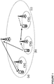
- Figure 1 Examples hereof with Closed Subscriber Group (CSG) cells are given in Figure 1 , where in case (a), a macro user with no access to the CSG cell will be interfered by the HeNB, in case (b) a macro user causes severe interference towards the HeNB and in case (c), a CSG user is interfered by another CSG HeNB.
- Heterogeneous deployments are not limited to those with CSG involved.
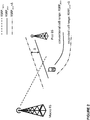
- FIG. 2 Another example is illustrated in Figure 2 , where the need for enhanced ICIC techniques for DL is particularly crucial when the cell assignment rule diverges from the RSRP-based approach, for example, towards pathloss- or pathgain-based approach, sometimes also referred to as the cell range expansion when adopted for cells with a transmission power lower than neighbor cells.
- the cell range expansion of a pico cell is implemented by means of a parameter ⁇ .
- the pico cell is expanded without increasing its power, just by changing the reselection threshold, for example, the user equipment selects the cell of the pico BS as the serving cell when RSRP pico + ⁇ RSRP macro , where RSRP macro is the received signal strength measured for the cell of macro BS and RSRP pico is the signal strength measured for the cell of pico BS.
- ABS Almost Blank Subframe
- eNodeBs eNodeBs
- restricted measurement patterns for user equipments.
- a pattern that may be configured for eICIC is a bit string indicating restricted and unrestricted subframes characterized by a length and periodicity, which are different for FDD and TDD (40 subframes for FDD and 20, 60 or 70 subframes for TDD). Only DL patterns have been specified for interference coordination in 3GPP, although patterns for UL interference coordination are also known.
- An ABS pattern is a transmit pattern at a radio node transmitting radio signals.
- the ABS pattern is also cell-specific and may be different from the restricted measurement patterns signaled to the user equipment.
- ABS comprises a low-power and/or low-transmission activity subframes.
- ABS patterns may be exchanged between eNodeBs via X2, but these patterns are not signaled to the user equipment, unlike the restricted measurement patterns.
- Restricted measurement patterns for example, "time domain resource restriction patterns", as described in 3GPP TS 36.331, are configured to indicate to the user equipment a subset of subframes for performing measurements. This may typically be done in lower interference conditions, where the interference may be reduced, for example, by means of configuring MBSFN subframes or ABS subframes at interfering eNodeBs, for example, at least in some examples a restricted measurement pattern for a measured cell overlaps, at least partly, with MBSFN subframes or ABS subframes of a strongly interfering cell.
- Restricted measurement patterns may, however, be also configured for user equipments with good interference conditions, for example, receiving a measurement pattern may be not necessarily an indication of expected poor signal quality.
- a measurement pattern may be configured for a user equipment in the cell range expansion zone where typically high interference is expected, but a measurement pattern may also be configured for user equipments located close to the serving base station where the signal quality is typically good which may be for the purpose of enabling higher-rank transmission modes, for example, rank-two transmissions.
- Restricted measurement patterns are in general user equipment-specific, although it is known that such patterns may be broadcasted or multicasted. Three patterns are currently specified in the standard to enable restricted measurements. The three patterns are a serving-cell pattern for RLM and RRM measurements, a neighbor-cell pattern for RRM measurements and a serving-cell pattern for CSI measurements.
- Transmit patterns and measurement patterns are means for coordinating inter-cell interference in wireless network and improve measurement performance.
- inter-cell interference coordination techniques and measurement performance may also be improved by using more advanced receiver techniques, for example, interference suppression or interference cancellation techniques.
- WO 2011/142715 A1 discloses a method and a network node for controlling configuration of parallel measurements to be performed by a user equipment operating in a wireless communication system.
- a network node such as a positioning server or a eNodeB
- obtain information on measurements requested by another network node the network node is able to configure the user equipment with a set of measurements that does not exceed at least one predetermined threshold for parallel reporting criteria.
- the performance of parallel measurements and/or channel receptions does not take into account the use of an enhanced receiver.
- a measuring node may be requested to perform more measurements than the measuring node is capable of carrying out. Therefore, degradation in performance and an unnecessary waste of system resources may happen.
- At least one example object of the example embodiments presented herein may be to provide optimized parallel measurements and/or channel receptions by taking into account the different elements of a wireless network.
- At least one example advantage of the example embodiments presented herein may be the assurance of a node's awareness of a measuring device's capability with respect to resource usage due to using an enhanced receiver.
- Another example advantage may be a node's ability to configure measurements and/or channel receptions for a measuring device while accounting for the usage of the enhanced receiver.
- a further example advantage may be the user equipment's ability to adaptively configure measurements and channels while accounting for a usage of the enhanced receiver.
- Another example advantage is being having the ability, in a controlled way, to avoid configuring too many measurements and channels for a user equipment which demands excessive usage of the enhanced receiver and may go beyond the user equipment's capability.
- a further example advantage may be keeping the user equipment complexity (e.g., processing power, power consumption and memory) at a reasonable level, while ensuring the minimum user equipment capability to perform a certain amount of measurements and/or channel receptions involving the enhanced receiver.
- some of the example embodiments are directed towards a method, in a radio node, for adapting parallel measurements and/or channel receptions when an enhanced receiver is in use.
- the enhanced receiver is capable of improving performance by fully or partly eliminating an interference arising from at least one interfering source.
- the method comprises obtaining current information and/or type information.
- the current information is associated with a total number of current parallel measurements and/or channel receptions being performed.
- the type information is associated with a type of each parallel measurement and/or channel reception being performed.
- the method further comprises obtaining interference information, and adapting the number of current parallel measurements and/or channel receptions being performed.
- the adapting is based on the current information, the type information, and/or the interference information.
- the adapting further being based on at least one enhanced receiver characteristic.
- the radio node comprises processing circuitry configured to obtain current information and/or type information.
- the current information is associated with a total number of current parallel measurements and/or channel receptions being performed.
- the type information is associated with a type of each parallel measurement and/or channel reception being performed.
- the processing circuitry is further configured to obtain interference information, which is associated with interference.
- the processing circuitry is also configured to adapt the number of current parallel measurements and/or channel receptions being performed.
- the adapting is based on the current information, the type information, and/or the interference information.
- the adapting further being based at least one enhanced receiver characteristic.
- Some of the example embodiments are directed towards a method, in a network node, for configuring measurements and/or channel receptions for a radio node by accounting for an enhanced receiver utilization.
- the enhanced receiver is capable of improving performance by fully or partly eliminating an interference arising from at least one interfering source.
- the network node is comprised in a radio network.
- the method comprises determining a number of parallel measurements and/or channel receptions being performed by the radio node.
- the method further comprises determining the radio node's capability to perform measurements and/or adapt the number of parallel measurements being performed and/or receive channels based on at least one characteristic of an enhanced receiver.
- the method further comprises sending, to the radio node or another network node, at least one instruction, based on the determined number of measurements and/or channel receptions and the determined capability, to perform measurements or adapt the number of parallel measurements being performed and/or receive one or more channels, based on at least one characteristic of an enhanced receiver.
- Some of the example embodiments are directed towards a network node for configuring measurements and/or channel receptions for a radio node by accounting for an enhanced receiver utilization.
- the enhanced receiver is capable of improving performance by fully or partly eliminating an interference arising from at least one interfering source.
- the network node is comprised in a radio network.
- the network node comprises processing circuitry configured to determine a number of parallel measurements and/or channel receptions being performed by the radio node.
- the processing circuitry is further configured to determine the radio node's capability to perform measurements and/or adapt the number of parallel measurements being performed and/or receive channels, based on at least one characteristic of the enhanced receiver.
- the network node further comprises interface circuitry configured to send, to the radio node or another network node, at least one instruction, based on the determined number of measurements and/or channel receptions and the determined capability, to perform measurements or adapt the number of parallel measurements being performed and/or receive one or more channels, based on at least one characteristic of the enhanced receiver.
- 3GPP TS 36.133 specifies requirements on user equipment capabilities for support of event triggering and reporting criteria.
- the current requirements are primarily defined for the mobility measurements.
- the requirements comprise a set of reporting criteria categories, the number of reporting criteria per category that user equipment shall be able to support in parallel, and the maximum total number of reporting criteria.
- the current set of reporting criteria comprises three measurement categories used for mobility: intra-frequency, inter-frequency and inter-RAT measurements.
- the intra-frequency category measurements for up to 9 E-UTRAN intra-frequency cells may be configured in parallel.
- measurements of up to 7 E-UTRAN inter-frequency cells may be configured in parallel.
- inter-RAT up to 5 parallel measurements per supported RAT are supported.
- the maximum total number of reporting criteria is currently 30. This means depending upon the user equipment capability, for example, inter-RAT capabilities, the eNodeB may configure the user equipment to perform up to 30 measurements in parallel. As long as the measurement configuration does not exceed the reporting criteria requirements above, the user equipment is required to meet the relevant performance requirements, for example, measurement reporting delay, measurement time, measurement accuracy of the configured measurements, etc.
- Table 1 Requirements for reporting criteria per measurement category Measurement category E cat Note Intra-frequency 9 E-UTRA intra-frequency cells Intra-frequency UE Rx-Tx time difference 2 Intra-frequency UE Rx-Tx time difference measurements reported to E-UTRAN via RRC and to positioning server via LPP. Applies for UE supporting both LPP and UE Rx-Tx time difference measurement.
- Intra-frequency RSTD 1 Intra-frequency RSTD measurement reporting for UE supporting OTDOA 1 report capable of minimum 16 cell measurements for the intra-frequency Inter-frequency 7 E-UTRA inter-frequency cells
- the parallel measurement requirements do not take into account whether any interference mitigation technique is applied for at least some of the measurements performed in parallel, where the measurements may be, for example, intra-frequency measurements, inter-frequency measurements, inter-RAT measurements, or measurements with carrier aggregation. There are currently no requirements or rules related to the number of parallel measurements at least one of which assumes the use of, involves or requires enhanced receiver techniques.
- no signaling means to indicate to other nodes (e.g., an eNodeB, home eNodeB, positioning node, or MDT node) the user equipment ability, or capability, to perform a certain number of parallel measurements while using, for example, at least one or more of the enhanced receiver techniques.
- nodes e.g., an eNodeB, home eNodeB, positioning node, or MDT node
- the measuring node e.g., a user equipment, wireless device or a radio node in general
- the measuring node may be requested to perform more measurements than the measuring node is capable to carry out in parallel, which may degrade performance but also may require prioritization of the measurements while accounting for the use of the enhanced receiver.
- Such methods are also covered by the example embodiments presented herein.
- Some of the example embodiments presented herein may comprise methods in user equipment of adapting the parallel measurements and/or control channel receptions, for example, common, user equipment specific, broadcast, multicast, etc., when using an enhanced receiver.
- Some of the example embodiments may comprise adaptation of parallel measurements and/or channel receptions which may be performed based on one or more characteristics associated with the enhanced receiver, radio conditions, activity state, etc.
- Some of the example embodiments may comprise the adaptation being based on pre-defined rules/requirements, which may be configured by the network node.
- Some of the example embodiments may comprise methods in user equipment for signaling a user equipment capability of adapting the parallel measurements and/or control channels when using an enhanced receiver to the network node.
- Some of the example embodiments may comprise methods in network node of taking into account the user equipment capability and/or pre-defined requirements related to adapting the parallel measurements and/or control channels when configuring the parallel reporting criteria and measurements/channels when the user equipment uses the enhanced receiver.
- the example embodiments will be presented as follows. First, an overview of a radio network, in which the example embodiments may be utilized, is provided under the subheading 'Radio Network Overview'. Thereafter, examples of how the parallel measurements and/or channel receptions when an enhanced receiver is in use may be adapted are provided under the subheading 'Interference Mitigation/Cancellation Techniques and Parallel Measurements'. Under the subheading 'Signaling Enhancements', examples of different types of information which may be signaled to and from various nodes in the network, to assist in the adaption, is provided.
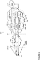
- FIG. 3 illustrates positioning architecture in an LTE system which features the positioning node 140.
- the positioning architecture may comprise the user equipment 101 which may be configured to perform positioning measurements.
- the user equipment 101 may be in communication with a base station 103 (e.g., base station 103A or 103B).
- the base station 103 may be in communication with a core network comprising a Serving Gateway (SGW) 109, a Packet Data Network Gateway (PGW) 111 and a Mobility Management Entity (MME) 107.
- SGW Serving Gateway
- PGW Packet Data Network Gateway
- MME Mobility Management Entity
- the base station 103 may also be in communication with a Location Measurement Unit (LMU) 102 which may assist in preforming measurements.
- LMU Location Measurement Unit
- the core network may also comprise a number of positioning nodes, for example, a Gateway Mobile Location Centre (GMLC) 105, an Enhanced Serving Mobile Location Centre (E-SMLC) 115 and/or a Secure User Plane Location Platform (SLP) 113.
- SLP 113 may comprise two components, SPC 113b and SLC 113a, which may also reside in different nodes.
- SPC 113b has a proprietary interface with E-SMLC 119, and LIp interface with SLC 113a, and the SLC part of SLP 113 communicates with P-GW (Packet Data Network Gateway) and External LCS Client.
- P-GW Packet Data Network Gateway
- the GMLC 105 may be used to request routing information from the Home Location register (HLR) or Home Subscriber Server (HSS). The GMLC 105 may also be used to positioning requests to the Visited Mobile Switching Centre (VMSC), Serving GPRS Support Node (SGSN) or Mobile Switching Centre (MSC) Server and receive final location estimates from the corresponding entity.
- the E-SMLC 115 may communicate with the user equipment 101 for location services and assistance data delivery using an LPP protocol.
- the E-SMLC 115 may also communication with the base station 103 of assistance data purposes using an LPPa protocol.
- the SLP 113 may be responsible for coordination and administrative functions to provide location services.
- the SLP 113 may also be responsible for positioning functions.
- the SLP 113 is a positioning node in the user plane.
- a radio node may be a measuring node, for example any type base station or a user equipment. It should be appreciated that the terms user equipment, measuring node and base station (or eNodeB) may be interchangeable. Specifically, embodiments (e.g., embodiments directed towards the adaption of parallel measurements and/or channel receptions) which are described solely with a user equipment may also be applied to a measuring node or base station and vice versa.
- a network node may refer to any form of base station or positioning node.
- a position node may further be a SLP or E-SMLC.
- base station or eNodeB
- positioning node may be interchangeable. Specifically, embodiments (e.g., embodiments directed towards providing instructions or configurations for parallel measurements and/or channel receptions) which are described solely with a base station may also be applied to a positioning node and vice versa.
- the enhanced receiver techniques addressed in the example embodiments presented herein may be applied to any physical signal (e.g., physical signals in general, reference signals, cell-specific or user equipment-specific reference signals, synchronization signals, etc.) or channel (e.g., broadcast channel, data channel, control channel, etc.).
- Some examples of enhanced receiver techniques are interference cancellation, interference rejection combining, and interference suppression.
- the enhanced receiver techniques may thus apply, for example, to radio measurements and/or channel reception.
- the measuring node adapts the number of parallel measurements and/or control/common/broadcast/multicast channel reception, which may be performed when enhanced receiver is used for performing at least one measurement and/or for control/common/broadcast/multicast channel reception.
- the parallel measurements for user equipment herein refer to the event triggering and reporting criteria, which may belong to one or more measurement categories such as intra-frequency, inter-frequency, carrier aggregation, inter-RAT, positioning measurement categories, etc. Examples of control channels are BCH, PCH, etc.
- the user equipment may perform only 7 intra-frequency measurements in parallel when it uses enhanced receiver for doing intra-frequency measurements.
- the adaptation of parallel measurements and/or control/common/broadcast channel reception performed by the measuring node may also depend upon one or more characteristics of the enhanced receiver.
- An example characteristic of the enhanced receiver may be a number of interferers or interfering transmitters or interfering cells, whose interference is fully or partly eliminated by the receiver. Another example characteristic may be a signal level of interferers, for example, received signal strength of interferer. A further example may be type of channels or signals on which enhanced receiver is used, for example, reference signals, synchronization signals, broadcast channel, etc. Another example characteristic of the enhanced receive is number of channels or signals on which enhanced receiver is used. A further example is type of control channel received using advanced receiver, or type or category of measurements, for example, intra-frequency, RSRP, RSRQ, timing measurements, positioning measurements, etc.
- Yet another example of a characteristic of the enhanced receiver may be the availability and the detail level of the assistance information used by the enhanced receiver, as well as how much the enhanced receiver depends on the assistance information provided by the network (the assistance data may. For example, the configuration of interfering signals, related cell information, etc. For example, if the number of interferers is 1 then the user equipment may perform up to 7 intra-frequency measurements in parallel. But if the number of interferers is increased to 2 then the user equipment may perform up to 6 or 5 intra-frequency measurements in parallel.
- the adaptation ability may also be associated with a specific activity state and may depend on the state, e.g., a DRX state and non-DRX state, or an IDLE mode or CONNECTED mode. For example, in a low-activity state the adaptation ability may be lower compared to a higher activity state.
- the lower adaptation may mean a smaller difference with and without accounting for the enhanced receiver in a specific state (e.g., IDLE or DRX), compared to another state (e.g., CONNECTED or non-DRX, respectively), which may occur because the user equipment has already a too limited amount of measurements in this state so that limiting it even further may harm the performance.
- a specific state e.g., IDLE or DRX
- another state e.g., CONNECTED or non-DRX, respectively
- the measurement capability of different user equipments may be different with respect to the use of the enhanced receiver. According to some of the example embodiments, this difference may be provided by the presence of low-cost devices.
- the adaptation may also be associated with the radio characteristics.
- radio characteristics are a type of radio environment such as indoor, urban, rural, a level of signal dispersion, etc., and/or a user speed.
- the user equipment may be able to perform fewer measurements in parallel since more processing may be required.
- the number of measurements and/or control/common/broadcast channel receptions that may be performed in parallel is less if the measuring node applies the enhanced receiver for at least N (N ⁇ 0) measurements and at least M (M ⁇ 0) channel receptions (M+N>0), compared to when no enhanced receiver technique is applied to any of the K (K ⁇ 0) measurements and L (L ⁇ 0) channel receptions that are performed in parallel without the enhanced receiver.
- N, M, K, and L may be applied to any of the example embodiments presented.
- the number of measurements and/or channel receptions, X and Y respectively, that may be performed in parallel when the enhanced receiver is used is equal the total number of measurements K and L, respectively, for example, the same as without the enhanced receiver, if the number of measurements N and/or number of channel receptions M for which the enhanced receiver is used does not exceed corresponding thresholds n and m or the aggregate threshold p (i.e., N ⁇ n , M ⁇ m or N+M ⁇ p ).
- the number of measurements and/or channel receptions, X and Y, that may be performed in parallel when the enhanced receiver is used depends on the number of signals to which the enhanced receiver technique is applied, for example, the number of cancelled or suppressed signals, denoted by R and S for measurements and channel receptions, respectively.
- a cancelled or suppressed signal may comprise an interfering signal from a neighboring cell or device.
- the cancelled/suppressed signal may or may not be the same for more than one measurement out of N measurements for which the enhanced receiver is used.
- the cancelled/suppressed signal may or may not be the same for more than one channel reception out of M channel receptions for which the enhanced receiver is used.
- the maximum number of measurements and/or channel receptions that can be performed in parallel when the enhanced receiver is used may be the same as when the enhanced receiver is not used.
- the adaptation of the number of measurements and/or channel receptions that can be performed in parallel when the enhanced receiver is used on the measurements and/or control channel depends upon the extent to which the enhanced receiver is used for the data channel reception. For example, if the user equipment does not use the enhanced receiver on a data channel, then the user equipment may be able to perform more measurements in parallel and/or receive more control/common/broadcast channels in parallel. The user equipment may not use the enhanced receiver on a data channel due to one or more reasons such as when there is no data reception, the data is sent using a robust transport format, the data comprises low bit rate channel, and/or the interference on the data channel is low (e.g. low system load), etc.
- the user equipment may receive a certain number of control channels (e.g., 4) in parallel using the enhanced receiver when for receiving data on the PCell and the baseline receiver for receiving data on the SCell.
- the same user equipment may receive a lower number of control channels (e.g., 2) when the enhanced receiver is used for receiving data on both the PCell and SCell.
- N and M may be the minimum number of measurements and channel receptions with the enhanced receiver, respectively, that the user equipment may be capable to perform.
- the measurements and/or channel receptions may or may not be limited to a certain set of time-frequency resources, for example, subframes configured with a certain periodicity, or certain time-frequency resources with specific interference conditions, for example, subframes indicated as restricted measurement subframes configured for eICIC.
- any of parameters X, Y, N, M, R, S may be defined statically, semi-statically or dynamically, and/or defined as the radio device capability.
- the parameters may also be defined as reporting criteria, which may be pre-defined or configured, for example, externally by software or autonomously by the device or received from a network node or radio network node.
- the parameters may also be defined separately for one, a subset, or all of time-frequency resources, for example, per frequency carrier or over a number of frequency carriers, per restricted measurement pattern or in configured positioning subframes.
- the parameters may also be defined separately for one, a subset, or for all measurements and/or channel reception types, for example, N RRM measurements or SI reading for M cells.
- measurements may comprise, but are not limited to, RRM measurements (e.g., cell identification, signal strength, signal quality), RLM measurements, mobility measurements (e.g., signal strength, signals quality), timing measurements (e.g., RTT, UE Rx-Tx, eNodeB Rx-Tx, Timing Advance, ToA, TDOA, RSTD, one-way propagation delay, etc.), positioning measurements (e.g., measurements for E-CID, AECID, fingerprinting, pattern matching, OTDOA, hybrid or other positioning methods), MDT measurements, channel state estimation measurements (e.g., CSI, CQI, RI, PMI, etc.), and/or direction measurements (e.g., AoA). It should be appreciated that these measurements may be intra-frequency, CA measurements, CoMP measurements, inter-frequency, inter-band, and/or inter-RAT.
- RRM measurements e.g., cell identification, signal strength, signal quality
- RLM measurements e.g., mobility measurements (e.g.,
- the channel reception may comprise receiving control, common, broadcast or multicast channels.
- Channels may be physical or logical channels.
- the control channels may be used for sending user equipment and/or cell specific information to the user equipment to control user equipment radio communication.
- Common and broadcast/multicast channels are generally sent to a group of user equipments or to all user equipments in a cell.
- User equipment specific information may be sent via dedicated control channels or by means of using user equipment specific codes and/or time frequency resources.
- control channels are PCFICH, PHICH, broadcast channels (e.g. PBCH, PDSCH, or D-BCH in LTE) carrying system information (SI), paging channels (e.g. PDCCH, PDSCH, etc. in LTE), etc.
- PBCH and PDSCH i.e. D-BCH
- MIB and SIBs respectively.
- signaling enhancements may comprise providing information associated with the measuring node's capability to adapt the number of parallel measurements and/or channel receptions when the enhanced receiver is used.
- the measuring node's capability to adapt the number of parallel measurements and/or control/common/broadcast/multicast channels when the enhanced receiver is used for performing the measurements and/or receiving the channels may be expressed as a pre-defined rule or it may be signaled by the measuring node to another node (e.g., to another user equipment or another network node). In other words any information associated with the adaptation ability described herein may be signaled by the measuring node to another user equipment or another network node.
- a user equipment may signal its capability to the serving radio node and/or to other network nodes (e.g., core network node, positioning node, MME, MDT, coordinating node, etc.).
- the measuring node capability may also be signaled by the network node to another network node.
- another network node may be a serving eNodeB (e.g., a femto BS), a neighboring eNodeB (e.g., a macro BS during a handover), or a positioning node.
- the capability may be signaled to another user equipment and the other user equipment may also signal it to another user equipment or network node.
- the information associated with the measuring node's capability to adapt parallel measurements and/or channel reception may comprise the basic ability of the measuring node to adapt the performance of parallel measurements and/or channel receptions when using the enhanced receiver.
- the capability may further comprise an ability to adapt related parameters, for example, any one or more of: N, M, S, R, X, Y, as described under the subheading 'Interference Mitigation/Cancellation Techniques and Parallel Measurements'.
- the capability may further provide information regarding types of the measurement and/or channel(s).
- the capability information may further comprise associated time-frequency resources, for example, subframes, patterns of time-frequency resources, restricted measurement patterns for eICIC, component carriers, frequencies, etc.
- the capability may also comprise information related to an enhanced receiver usage, for example, the number of currently configured measurements and/or channel receptions when the enhanced receiver is used and/or for which the enhanced receiver is used.
- any of the information described under the preceding subheading may be signaled in a number of ways, according to some of the example embodiments.
- a non-limited example of such signaling may be from one radio device to another radio device (e.g., the user equipment).
- Signaling may also be provided from the first radio device to the radio network node (e.g., the eNodeB), from the first radio device to the network node (e.g., a positioning node, SON, etc.), from the radio network node to another radio network node, from the radio network node to the network node, from the radio network node to the second radio device signaling of the information related to the first radio device and/or from the network node to the second radio device signaling of the information related to the first radio device.
- the radio network node e.g., the eNodeB
- the network node e.g., a positioning node, SON, etc.
- the information signaled as described above may be provided by the source node to the target node in a number different ways, according to some of the example embodiments.
- a non-limiting example of providing such information may be upon receiving an explicit request from the target node, for example, the eNodeB requesting the user equipment to send its capability.
- a further example may be upon receiving an explicit request from another node, for example, the eNodeB requesting the user equipment to send its capability to the positioning node or one eNodeB requesting the user equipment to send its capability to another eNodeB.
- a further example may be without receiving an explicit request from a node, for example, without the eNodeB requesting the user equipment to send its capability.
- the capability may be sent at a pre-defined occasion such as an initial setup, after a cell change, when an interference level changes beyond a certain level, when accessing a node, and/or when setting up a service such as a positioning session and/or configuring positioning measurements, etc.
- a further example may be in response to a triggering condition.
- a triggering condition may be based on a comparison of a signal strength level or a signal quality level to a certain threshold. For example, a triggering condition may occur when the serving cell quality drops below a threshold or when the number of currently performed measurements exceeds a threshold.
- Other triggering condition examples are a cell change event, a handover event, connection and/or session establishment, etc.
- Measurements and/or channel receptions may be requested from the measuring node by any number of different nodes, which may not be aware of the each other's decision or configuration. According to some of the example embodiments, it is assured that the number of configured/requested measurements and/or channel receptions with the enhanced receiver, or the number of measurements and/or channel receptions performed when the enhanced receiver is used, does not exceed the measuring node's capability related to the enhanced receiver, as described under the subheadings 'Interference Mitigation/Cancellation Techniques and Parallel Measurements' and 'Signaling Enhancements'.
- the first node may determine any number of factors or criteria in configuring measurements or channels when the enhanced receiver is in use.
- criteria may be currently configured reporting criteria in total, and/or currently configured reporting criteria for which the enhanced receiver is used (also likely to be used or may need to be used), for example, due to an expected low signal quality.
- Further examples may comprise whether the enhanced receiver is used, for example, based on the measuring node's capability or from other information.
- Another example may be measurement types for which the enhanced receiver is currently used. It should be appreciated that the aforementioned information may be obtained autonomously, for example, and/or by explicit signaling from another node or the measuring node, as described under subheading 'Nodes and Devices Involved'.
- the radio node may configure/schedule/request the measuring node to perform measurements and/or channel receptions.
- the network node may prioritize some of the measurements and/or channel receptions.
- prioritizing may also be provided by exploiting the knowledge about the user equipment's ability to adapt measurements and channel receptions when using the enhanced receiver.
- the network node may also differentiate between the measurements and channel receptions that require, or are likely to require, a use of the enhanced receiver and the measurements and channel receptions that may be performed without the enhanced receiver, for example, the performance may degrade but would still meet a performance requirement or would not impact the performance of other measurements and/or channels.
- cell search using the enhanced receiver may be prioritized over paging channel reading.
- the user equipment when the total number of configured parallel measurement criteria exceeds the limit, for example any form of a pre-defined requirement, and the user equipment, or measuring node in general, uses the enhanced receiver for at least some measurements and/or channel receptions, the user equipment may adapt the number of parallel measurements to perform and/or channels to receive.
- the limit for example any form of a pre-defined requirement
- the user equipment, or measuring node in general uses the enhanced receiver for at least some measurements and/or channel receptions
- the user equipment may adapt the number of parallel measurements to perform and/or channels to receive.
- the adaptation may be based purely on a pre-defined rule, which may be realized by set of pre-defined requirements.
- the user equipment may adapt the number as well as specific measurements and/or channel receptions according to the pre-defined requirements.
- the adaptation may be done autonomously by the user equipment but within the limit defined by a pre-defined rule, which may also be realized by a set of pre-defined requirements.
- the user equipment may adapt the number of parallel measurements and/or channel receptions according to the limit defined by the pre-defined requirement.
- the user equipment may itself decide which of the measurements should be prioritized or performed and which should not be performed.
- the user equipment may have to stop the reporting of another, for example, lower priority, measurement or stop the reading of a lower priority channel in favor of a measurement/channel with a higher priority.
- the user equipment may determine which of the measurements and/or channel receptions are to be performed when the total number of configured/requested measurements and/or channel receptions is larger than X or Y, respectively.
- the user equipment may make a determination when the number of configured/requested measurements and/or channel receptions with the enhanced receiver exceeds N or M, respectively, or the number of measurements and/or channel receptions for which the enhanced receiver may be performed, and those for which the enhanced receiver is to be used should not exceed N, M, S or R.
- the user equipment may use a prioritization approach to determine which measurements to perform and/or which channels to receive, while accounting for its ability to perform parallel measurements and/or channel receptions when the enhanced receiver is used for at least some of them.
- the user equipment may choose not to use the enhanced receiver if it may perform the measurement without the enhanced receiver (perhaps with lower quality) and at the same time also perform another measurement which it would not be able to perform if the enhanced receiver would be used for the first measurement.
- the autonomous decision in the user equipment may be based on a pre-defined rule.
- a pre-defined rule may be that a particular type of measurement and/or channel receptions shall always be performed or shall be performed with the enhanced receiver, or has a higher priority, where the type may be associated, for example, with a purpose (e.g., RRM, mobility, positioning, emergency applications, etc.) or frequency (e.g., intra-frequency, inter-frequency, CA, or inter-RAT).
- a pre-defined rule may be measurements and/or channel receptions in a specific environment or specific cells shall be performed with or without the enhanced receiver, for example, in a proximity of an interfering radio node or another wireless device or under coverage of a CSG cell.
- a further example of a pre-defined rule may be measurements and/or channel receptions shall be performed with or without the enhanced receiver when a list of cells is provided.
- Another example of the pre-defined rule may be measurements and/or channel receptions in specific interference conditions shall be performed with or without the enhanced receiver, for example, when a condition based on thresholds for the received signal strength or quality of one or more cells holds or when the user equipment is in the cell range expansion zone.
- a further example of the pre-defined rule may be measurements and/or channel receptions shall be performed with or without the enhanced receiver in specific time-frequency resources, for example, when a restricted measurement pattern is provided.
- Step 1 Obtain the current number and types of measurements and channel receptions performed in parallel.
- Step 2 Determine the set of measurements and/or channel receptions for which the enhanced receiver is currently used.
- Step 3 (Optional) Determine the set of measurements and/or channel receptions for which the enhanced receiver may not be used, but the minimum required quality is still likely to be achieved.
- Step 4 (Optional) Prioritize measurements and/or channel receptions with respect to their importance and the 'cost' of usage of the enhanced receiver for each of them (e.g., the estimation of one channel estimation may be reused by the enhanced receiver for improving performance of more than one measurements and thus may be less 'costly' as if each measurement would require separate channel estimation for the signal to be cancelled).
- Step 5 Adapt the number of current measurements and/or channel receptions based on the user equipment's capability to perform parallel measurements and/or channel receptions with enhanced receiver.
- Such adaption may comprise, for example, reducing a usage of the enhanced receiver and increasing the total number of measurements, choosing to not perform at least one measurement and/or channel reception that requires use of the enhanced receiver, and/or reducing the intensity of the enhanced receiver being used, for example, not cancelling more than one interferer.
- reporting criteria may be configured according to some of the examples provided in Table 2 below: Table 2.
- Example reporting criteria accounting for the enhanced receiver Measurement category E cat Note
- Intra-frequency 9 E-UTRA intra-frequency cells
- E cat for Intra-frequency is applied per serving frequency.
- Example Note 2 When the user equipment performs measurements/receptions with the enhanced receiver, the number of measurements may also comprise the minimum number of aggressor interferers the receiver is capable to deal with. or: Another example Note 2: When the measurements require the use of the enhanced receiver, the number of parallel measurements may be lower.
- the measuring node may be expected to meet certain performance requirements, for example, report the measurements within a certain time and comply with a certain accuracy level.
- the measurement time or channel reading time for at least one measurement or channel may be longer and/or the accuracy may be degraded.
- the number of cell identifications performed by the measuring node may be smaller when the user equipment uses the enhanced receiver than if the user equipment would not use the enhanced receiver to deal with the interference.
- the required minimum number of reported identified cells may be smaller if the enhanced receiver is used for the cell identifications or other measurements and/or channel receptions performed in parallel.
- the measuring node is using the enhanced receiver when the measurement and/or channel reception is performed in certain interference conditions, for example, at a signal level below a certain threshold (e.g., the threshold may correspond to when the measuring node is capable of performing the same measurement and/or channel reception without using the enhanced receiver and meet the corresponding requirement).
- a certain threshold e.g., the threshold may correspond to when the measuring node is capable of performing the same measurement and/or channel reception without using the enhanced receiver and meet the corresponding requirement.
- usage of the enhanced receiver is associated with the configuring node and/or measuring node with additional power consumption, for example, more intensive usage of the enhanced receiver is likely to result in higher power consumption and faster battery energy consumption.
- the adaption described in this section enables measurement and channel configurations that are energy efficient. According to some of the example embodiments, this may be achieved by the methods described in any of the previous sections combined with the power and energy consumption aspect described herein. This also applies to prioritization approaches in the measuring or configuring nodes with respect to using the enhanced receiver while accounting for power/energy.
- any one of the embodiments described until this part may further be enhanced with the information about the battery level and adaptation of the measurements configuration and/or channel configuration by the configuring node or measuring node.
- Such enhancement may be based on, for example, the measuring device's capability of parallel measurements and channel receptions when using the enhanced receiver, a current measurement and channel configuration, a power or battery energy level indication, and/or a power-saving or energy-consumption mode indication.
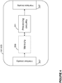
- FIG 4 illustrates an example of a radio node 101/103 which may incorporate some of the example embodiments discussed above.
- the radio node may be a measuring node, user equipment 101 or any type of base station 103.
- the radio node 101/103 may comprise interference circuitry 207 configured to receive and transmit any form of communications or control signals within a network.
- the interference circuitry 207 may be comprised as any number of transceiving, receiving, and/or transmitting units or circuitry. It should further be appreciated that the interference circuitry 207 may be in the form of any input/output communications port known in the art.
- the interference circuitry 207 may comprise RF circuitry and baseband processing circuitry (not shown).
- the radio node 101/103 may further comprise at least one memory unit or circuitry 209 that may be in communication with the interference circuitry 207.
- the memory 209 may be configured to store received or transmitted data and/or executable program instructions.
- the memory 209 may also be configured to store any form of predefined rules of information related to the example embodiments presented herein.
- the memory 209 may be any suitable type of computer readable memory and may be of volatile and/or non-volatile type.
- the radio node 101/103 may further comprise processing circuitry 211 which may be configured to adapt the parallel measurements and/or channel receptions based on a usage of an enhanced receiver.
- the processing circuitry 211 may also be configured to provide configuration instructions to the user equipment, in the case where the radio node is a base station 103.
- the processing circuitry 211 may be any suitable type of computation unit, e.g. a microprocessor, digital signal processor (DSP), field programmable gate array (FPGA), or application specific integrated circuit (ASIC) or any other form of circuitry. It should be appreciated that the processing circuitry need not be provided as a single unit but may be provided as any number of units or circuitry.
- Figure 5 illustrates an example of a network node 103/140 which may incorporate some of the example embodiments discussed above.
- the network node may be a base station 103 or a positioning node 140.
- the network node 103/140 may comprise interference circuitry 307 configured to receive and transmit any form of communications or control signals within a network.
- the interference circuitry 307 may be comprised as any number of transceiving, receiving, and/or transmitting units or circuitry. It should further be appreciated that the interference circuitry 307 may be in the form of any input/output communications port known in the art.
- the interference circuitry 307 may comprise RF circuitry and baseband processing circuitry (not shown).
- the network node 103/140 may further comprise at least one memory unit or circuitry 309 that may be in communication with the interference circuitry 307.
- the memory 309 may be configured to store received or transmitted data and/or executable program instructions.
- the memory 309 may also be configured to store any form of predefined rules of information related to the example embodiments presented herein.
- the memory 309 may be any suitable type of computer readable memory and may be of volatile and/or non-volatile type.
- the network node 103/140 may further comprise further processing circuitry 311 which may be configured to adapt the parallel measurements and/or channel receptions based on a usage of an enhanced receiver.
- the processing circuitry 311 may also be configured to provide configuration instructions to the user equipment for providing the adaptation.
- the processing circuitry 311 may be any suitable type of computation unit, e.g. a microprocessor, digital signal processor (DSP), field programmable gate array (FPGA), or application specific integrated circuit (ASIC) or any other form of circuitry. It should be appreciated that the processing circuitry need not be provided as a single unit but may be provided as any number of units or circuitry.
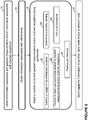
- Figure 6 is a flow diagram depicting example operations which may be taken by the radio node 101/103 of Figure 4 , during the adaption of parallel measurements and/or channel receptions when an enhanced receiver is in use, according to some of the example embodiments.
- Figure 6 comprises some operations which are illustrated with a darker border and some operations which are illustrated with a lighter border.
- the operations which are comprised in a darker border are operations which are comprised in the broadest example embodiment.
- the operations which are comprised in a lighter border are example embodiments which may be comprised in, or a part of, or are further operations which may be taken in addition to the operations of the border example embodiments. It should be appreciated that these operations need not be performed in order. Furthermore, it should be appreciated that not all of the operations need to be performed.
- the example operations may be performed in any order and in any combination.
- the radio node 101/103 is configured to obtain 10 current information and/or type information.
- the current information is associated with a total number of current parallel measurements and/or channel receptions being performed.
- the type information is associated with a type of each parallel measurement and/or channel reception being performed.
- the processing circuitry 211 is configured to obtain the current and/or the type information.
- the current and/or type information may be obtained from another radio node or network node. According to some of the example embodiments, the current and/or type information may be obtained by the radio node 101/103 itself. Further explanation and examples of the type of information which may be obtained, and how such information may be obtained, is described at least under the subheading 'Signaling Enhancements'.
- the radio node 101/103 is further configured to obtain 14 interference information.
- the processing circuitry 211 is configured to obtain the interference information.
- the interference information may comprise at least one of a number of interfering radio nodes or interfering cells, time-frequency resources associated with interfering transmissions, received signal strength of at least one interferer, a type of interfering signals or channels, a measurement pattern, or assistance data for interference handling.
- the interference information may be obtained from another radio node or network node.
- the interference information may be obtained by the radio node 101/103 itself.
- the current, type and interference information may comprise any form of information or parameter discussed herein. Further explanation and examples of the type of information which may be obtained, and how such information may be obtained, is described at least under the subheading 'Signaling Enhancements'.
- the radio node 101/103 is further configured to adapt 18 the number of current parallel measurements and/or channel receptions being performed.
- the adapting is based on the current information, the type information, and/or the interference information, and at least one enhanced receiver characteristic.
- the processing circuitry 211 is configured to adapt the number of current parallel measurements and/or channel receptions being performed.
- the at least one enhanced receiver characteristic may comprise any one or more of a number of interferers, a number of interfering transmitters, a number of interfering cells whose interference is fully or partly eliminated by the enhanced receiver, received signal strength of interferes whose interference is fully or partially eliminated by the enhanced receiver, types of channels or signals whose interference is fully or partially eliminated by the enhanced receiver, a number of different types of channels or signals on which the enhanced receiver is sued, an ability to handle high interference without or with assistance data for interference handling, the enhanced receiver's ability to handle the interference by applying interference cancellation, the enhanced receiver's ability to handle the interference by applying interference suppression, and the enhanced receiver's ability to handle the interference by applying interference rejection.
- the adapting 18 may be further based on at least one of an amount of usage of an enhanced receiver, an amount of power consumption, a measurement pattern and/or a battery energy level.
- the adapting 18 may be performed autonomously, based on a pre-defined rule, and/or based on adaption instructions received from another radio node or a network node.
- the adapting may be further based on an activity state of the radio node, a type of radio environment in which the radio node is located and/or a speed of the radio node.
- the adapting 18 may further comprise controlling 20 a usage of the enhanced receiver.
- the processing circuitry 211 may be configured to control the usage of the enhanced receiver.
- the adapting 18 may further comprising controlling 22 at least one parameter related to the current number of parallel measurements and/or channel receptions.
- the processing circuitry 211 may be configured to control at least one parameter related to the current number of parallel measurements and/or channel receptions.
- the adapting 18 may further comprise providing 24 a priority ranking of parallel measurements or channel receptions based on a level of interference.
- the processing circuitry 211 may be configured to provide the priority ranking of parallel measurements or channel receptions based on the level of interference.
- the adapting 18 may further comprising halting 26 a performance of at least one measurement and/or channel reception that requires use of the enhanced receiver.
- the processing circuitry 211 may be configured to halt the performance of the at least one measurement and/or channel reception that requires use of the enhanced receiver.
- the adapting 18 may further comprise reducing 28 an intensity of the enhanced receiver when a number of interferes requiring an enhanced receiver for a measurement or channel reception exceeds a threshold.
- the processing circuitry 211 may be configured to reduce the intensity of the enhanced receiver when the number of interferes requiring the enhanced receiver for a measurement or channel reception exceeds a threshold.
- the radio node 101/103 may be further configured to send 30 capability information to another radio node and/or to a network node.
- the capability information may indicate that the radio node is capable of adapting the number of currently performed parallel measurements and/or channel receptions based on the current information, type information and/or interference information and at least one enhanced receiver characteristic.
- the processing circuitry 211 may be configured to send the capability information to another radio node and/or to a network node.
- the capability information may comprise any one or more of the information associated with interference, a measurement pattern, an ability of the radio node to adapt the number of current parallel measurements and/or channel receptions being performed while using the enhanced receiver for performing the parallel measurements or channel receptions, information associated with the current number of parallel measurements and/or channel receptions, types of parallel measurements and/or channel reception being performed, time-frequency resources associated with the parallel measurements or channel receptions, and/or an ability of the radio node to adapt the number of current parallel measurements and/or channel receptions being performed while using the enhanced receiver for performing the parallel measurements or receiving the channels (adaptively to the enhance receiver usage, power consumption level, and/or battery energy level).
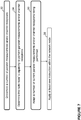
- Figure 7 is a flow diagram depicting example operations which may be taken by the network node 103/140 of Figure 5 , during the configuration of measurements and/or channel receptions for a radio node by accounting for an enhanced receiver utilization, according to some of the example embodiments.
- Figure 7 comprises some operations which are illustrated with a darker border and some operations which are illustrated with a lighter border.
- the operations which are comprised in a darker border are operations which are comprised in the broadest example embodiment.
- the operations which are comprised in a lighter border are example embodiments which may be comprised in, or a part of, or are further operations which may be taken in addition to the operations of the border example embodiments. It should be appreciated that these operations need not be performed in order. Furthermore, it should be appreciated that not all of the operations need to be performed.
- the example operations may be performed in any order and in any combination.
- the network node 103/140 is configured to determine 32 a number of parallel measurements and/or channel receptions being performed by the radio node 101/103.
- the processing circuitry 311 is configured to determine the number of parallel measurements and/or channel receptions being performed by the radio node 101/103.
- the network node 103/140 is further configured to determine 34 the radio node's 101/103 capability to perform and/or adapt parallel measurements and/or receive channels.
- the processing circuitry 311 is configured to determine the radio node's 101/103 capability to perform and/or adapt parallel measurements and/or receive channels.
- the determining 34 may be based on capability information received from the radio node, another network node, and/or based on a predefined rule.
- the capability further comprises an ability of the radio node to adapt a number of measurements being performed and/or channel receptions, for example, while the enhanced receiver is in use for performing the parallel measurements or channel receptions.
- the capability may be based on at least one of information associated with the parallel measurements and/or information associated with channel receptions and at least one enhanced receiver characteristic.
- the capability may be further based on information associated with a level of interference from at least one interfering radio node and/or associated time-frequency resources.
- the capability may be further based on a measurement pattern, types of parallel measurements and/or channel reception being performed, and/or time frequency resources associated with the parallel measurements or channel receptions.
- the capability may further comprise an ability to adaptively enhance receiver usage, a power consumption level, and/or a battery energy level.
- the network node 103/140 is further configured to send 36, to the radio node 101/103 or another network node, at least one instruction.
- the at least one instruction is based on the determined number of parallel measurements and/or channel receptions and the determined capability.
- the instruction is directed towards performing or adapting one or more measurements and/or receiving one or more channels.
- the interface circuitry 307 is configured to send, to the radio node or another network node, the at least one instruction.
- the one or more measurements, and/or one or more received channels may be of a same or different type.
- the at least one instruction is further based on a level of interference from at least one interfering radio node or cell and/or at least one characteristic of the enhanced receiver. It should be appreciated that the level of interference may further comprise a number of interference radio nodes or interfering cells whose interference is at least partially eliminated by the enhanced receiver and/or a received signal strength of the at least one interfering radio node.
- the at least one instruction further comprises at least one reduction instruction for reducing a usage of the enhanced receiver an increasing a current number of parallel measurements being performed, halting at least one measurement and/or channel reception that requires a use of the enhanced receiver, and/or reducing an intensity of the enhanced receive.
- the at least one instruction may further be based on an activity state of the radio node, a type of radio environment in which the radio node is located, a power level of the radio node, and/or speed of the radio node.
- the network node 103/140 may be further configured to obtain at least one characteristic of the enhanced receiver.
- the at least one instruction may be further based on the at least one characteristic of the enhanced receiver.
- the at least one characteristic of the enhanced receiver may comprise a type or number of channel or signal utilized by the enhanced receiver, a type of control channel utilized by the enhanced receiver, and/or an availability or detail level of assistance information used by the enhanced receiver.
- the network node 103/140 may be further configured to apply 38 the at least one instruction, within the network node 103/140, and perform measurements based on the applying 38.
- the processing circuitry 311 may be configured to apply the at least one instruction, within the network node 103/140, and perform measurements based on the application.
- the network may also function as a measuring node.
- the term 'parallel measurements and/or channel receptions' may be interpreted as (1) at least one measurement and at least one other measurement being performed in parallel, (2) at least one channel and at least one other channel being received in parallel, or (3) at least one measurement being performed and at least one channel being received in parallel.
- radio device is a non-limiting term comprising any wireless device or radio node equipped with a radio interface allowing for at least receiving radio signals and/or performing measuring signals.
- a user equipment in its general sense herein is further interchangeably referred to as a radio device.
- Some examples of such radio device are PDA, laptop, mobile, sensor, fixed relay, mobile relay, a radio network node, a radio base station, a femto base station, a small base station using the terminal-like technology, a low-cost radio device.
- the radio device may further be capable of operating or performing measurements in one or more frequencies, carrier frequencies, component carriers or frequency bands.
- the radio devices may or may not use measurement gaps.
- the radio device may also operate in single- or multi-RAT or multi-standard mode (e.g., an example dual-mode UE may operate with any one or combination of WiFi and LTE).
- measuring node may comprise a base station, user equipment, or any form of wireless device in general (e.g., relays, eNodeB, HeNB).
- a first radio device is receiving and/or measuring signals from a second radio device (i.e., user equipment, radio base station, etc.).
- the first radio device may be associated with or served by a radio network node (e.g., a radio base station), wherein the radio network node may or may not be the same as the second radio device.
- a measurement performed by the first radio device may be requested or configured by a network node, wherein the network node may or may not be the same as the radio network node.
- Some examples of the network node are eNodeB, NodeB, RNC, positioning node, MDT node, SON node, O&M node, etc.
- a cell may be associated with the radio network node, wherein some examples of radio network nodes are eNodeB, Node B, macro/micro/pico radio base station, home eNodeB, relay, repeater, sensor, radio nodes transmitting physical signals, etc.
- a radio network node herein may comprise a radio node operating in one or more frequencies, carrier frequencies or frequency bands. It may be a radio node capable of CA. It may also be a single- or muti-RAT or multi-standard node, e.g., using the same or different base band modules for different RATs.
- a serving cell is in general used throughout the description for CA and non-CA systems.
- primary cell PCell
- SCell secondary cell
- a radio node may also be a radio node which does not create own cell, but still transmitting some DL signals or receiving some signals in UL.
- a subframe may be an LTE subframe or any time interval or time slot, which may be pre-defined.
- centralized network management node or "coordinating node” used herein is a network node, which may also be a radio network node, which coordinates radio resources with one or more radio network nodes and/or user equipments.
- the coordinating node are network monitoring and configuration node, OSS node, O&M, MDT node, SON node, positioning node, a gateway node such as Packet Data Network Gateway (P-GW) or Serving Gateway (S-GW) network node or femto gateway node, a macro node coordinating smaller radio nodes associated with it, etc.
- P-GW Packet Data Network Gateway
- S-GW Serving Gateway
- the signaling described in some of the example embodiments is either via direct links or logical links (e.g. via higher layer protocols and/or via one or more network nodes).
- signaling from a coordinating node may pass another network node, e.g., a radio node.
- a radio node e.g., a radio node.
- the example embodiments are not limited to LTE, but may apply with any Radio Access Network (RAN), single- or multi-RAT.
- Some other RAT examples are LTE-Advanced, UMTS, GSM, cdma2000, WiMAX, and WiFi.
- Embodiments and sections described herein may be considered as independent embodiments or may be considered in any combination with each other to describe non-limiting examples of the embodiments.
- a “device” as the term may be used herein, is to be broadly interpreted to include a radiotelephone having ability for Internet/intranet access, web browser, organizer, calendar, a camera (e.g., video and/or still image camera), a sound recorder (e.g., a microphone), and/or global positioning system (GPS) receiver; a personal communications system (PCS) user equipment that may combine a cellular radiotelephone with data processing; a personal digital assistant (PDA) that can include a radiotelephone or wireless communication system; a laptop; a camera (e.g., video and/or still image camera) having communication ability; and any other computation or communication device capable of transceiving, such as a personal computer, a home entertainment system, a television, etc.
- a device may be interpreted as any number of antennas or antenna elements.
- user equipment is a non-limiting term which means any wireless device, terminal, or node capable of receiving in DL and transmitting in UL (e.g. PDA, laptop, mobile, sensor, fixed relay, mobile relay or even a radio base station, e.g. femto base station).
- UL e.g. PDA, laptop, mobile, sensor, fixed relay, mobile relay or even a radio base station, e.g. femto base station.
- a cell is associated with a radio node, where a radio node or radio network node or eNodeB used interchangeably in the example embodiment description, comprises in a general sense any node transmitting radio signals used for measurements, e.g., eNodeB, macro/micro/pico base station, home eNodeB, relay, beacon device, or repeater.
- a radio node herein may comprise a radio node operating in one or more frequencies or frequency bands. It may be a radio node capable of CA. It may also be a single- or muti-RAT node.
- a multi-RAT node may comprise a node with co-located RATs or supporting multi-standard radio (MSR) or a mixed radio node.
- a computer-readable medium may include removable and non-removable storage devices including, but not limited to, Read Only Memory (ROM), Random Access Memory (RAM), compact discs (CDs), digital versatile discs (DVD), etc.
- program modules may include routines, programs, objects, components, data structures, etc. that perform particular tasks or implement particular abstract data types.
- Computer-executable instructions, associated data structures, and program modules represent examples of program code for executing steps of the methods disclosed herein. The particular sequence of such executable instructions or associated data structures represents examples of corresponding acts for implementing the functions described in such steps or processes.
Landscapes
- Engineering & Computer Science (AREA)
- Computer Networks & Wireless Communication (AREA)
- Signal Processing (AREA)
- Mobile Radio Communication Systems (AREA)
Claims (15)
- Verfahren in einem Funkknoten (101, 103) zum Anpassen von parallelen Messungen und/oder Kanalempfängen, wenn ein erweiterter Empfänger in Verwendung ist, wobei der erweiterte Empfänger fähig ist, Leistung durch vollständiges oder teilweises Eliminieren einer Störung zu verbessern, die sich aus mindestens einer störenden Quelle ergibt, wobei das Verfahren umfasst:Erlangen (10) von gegenwärtigen Informationen und/oder Typinformationen, wobei die gegenwärtigen Informationen mit einer Gesamtzahl von gegenwärtigen parallelen Messungen und/oder Kanalempfängen verbunden sind, die ausgeführt werden, und die Typinformationen mit einem Typ von jeder parallelen Messung und/oder jedem parallelen Kanalempfang verbunden sind, die bzw. der ausgeführt wird;Erlangen (14) von Störungsinformationen; undAnpassen (18) der Anzahl an gegenwärtigen parallelen Messungen und/oder Kanalempfängen, die ausgeführt werden, wobei das Anpassen auf den gegenwärtigen Informationen, den Typinformationen und/oder den Störungsinformationen basiert,dadurch gekennzeichnet, dass das Anpassen (18) weiter auf mindestens einer erweiterten Empfänger-Charakteristik basiert.
- Verfahren nach Anspruch 1, wobei das Erlangen (10) weiter das Empfangen (11) der gegenwärtigen Informationen, der Typinformationen und/oder der Störungsinformationen von einem anderen Funkknoten oder Netzwerkknoten umfasst.
- Verfahren nach einem der Ansprüche 1 bis 2, wobei die Störungsinformationen mindestens eines von einer Anzahl von störenden Funkknoten oder störenden Zellen, Zeit-Frequenz-Ressourcen, die mit störenden Übertragungen verbunden sind, empfangener Signalstärke von mindestens einem Störer, einem Typ von störenden Signalen oder Kanälen, einer Messstruktur oder Unterstützungsdaten für eine Störungsbehandlung umfassen.
- Verfahren nach einem der Ansprüche 1 bis 3, wobei das Anpassen (18) weiter auf mindestens einem von einem Umfang an Verwendung eines erweiterten Empfängers, einer Energieverbrauchsmenge, einer Messstruktur und/oder einem Batterieenergieniveau basiert.
- Verfahren nach einem der Ansprüche 1 bis 4, wobei das Anpassen (18) weiter das Steuern (20) einer Verwendung des erweiterten Empfängers umfasst.
- Verfahren nach einem der Ansprüche 1 bis 5, wobei das Anpassen (18) weiter das Steuern (22) von mindestens einem Parameter umfasst, der mit der gegenwärtigen Anzahl an parallelen Messungen und/oder Kanalempfängen verbunden ist, die ausgeführt werden.
- Verfahren nach einem der Ansprüche 1 bis 6, wobei das Anpassen (18) weiter das Bereitstellen (24) einer Prioritätseinstufung von parallelen Messungen oder Kanalempfang basierend auf einem Störungsgrad umfasst.
- Verfahren nach einem der Ansprüche 1 bis 7, wobei das Anpassen (18) weiter das Stoppen (26) eines Ausführens von mindestens einer Messung und/oder eines Kanalempfangs umfasst, die bzw. der die Verwendung des erweiterten Empfängers erfordert.
- Verfahren nach einem der Ansprüche 1 bis 8, weiter umfassend das Senden (30) von Fähigkeitsinformationen zu einem anderen Funkknoten (101, 103) und/oder Netzwerkknoten (103, 140), wobei die Fähigkeitsinformationen anzeigen, dass der Funkknoten fähig ist, die Anzahl an gegenwärtig ausgeführten parallelen Messungen und/oder Kanalempfängen basierend auf den gegenwärtigen Informationen, den Typinformationen und/oder den Störungsinformationen und der mindestens einen erweiterten Empfänger-Charakteristik anzupassen.
- Funkknoten (101, 103) zum Anpassen von parallelen Messungen und/oder Kanalempfängen, wenn ein erweiterter Empfänger in Verwendung ist, wobei der erweiterte Empfänger fähig ist, die Leistung durch vollständiges oder teilweises Eliminieren einer Störung zu verbessern, die sich aus mindestens einer störenden Quelle ergibt, wobei der Funkknoten umfasst:Verarbeitungsschaltungen (211), die konfiguriert sind, gegenwärtige Informationen und/oder Typinformationen zu erlangen, wobei die gegenwärtigen Informationen mit einer Gesamtzahl von gegenwärtigen parallelen Messungen und/oder Kanalempfängen verbunden sind, die ausgeführt werden, und die Typinformationen mit einem Typ von jeder parallelen Messung oder jedem parallelen Kanalempfang verbunden sind, die bzw. der ausgeführt wird;wobei die Verarbeitungsschaltungen (211) weiter konfiguriert sind, Störungsinformationen zu erlangen, und die Störungsinformationen mit einer Störung verbunden sind; unddie Verarbeitungsschaltungen (211) zudem konfiguriert sind, die Anzahl an gegenwärtigen parallelen Messungen und/oder Kanalempfängen anzupassen, die ausgeführt werden, wobei das Anpassen auf den gegenwärtigen Informationen, den Typinformationen und/oder den Störungsinformationen basiert,dadurch gekennzeichnet, dass das Anpassen weiter auf mindestens einer erweiterten Empfänger-Charakteristik basiert.
- Funkknoten (101, 103) nach Anspruch 10, wobei die mindestens eine erweiterte Empfänger-Charakteristik ein oder mehrere einer Anzahl von Störern, einer Anzahl von Störsendern, einer Anzahl von störenden Zellen, deren Störung durch den erweiterten Empfänger vollständig oder teilweise eliminiert ist, einer empfangenen Signalstärke von Störern, deren Störung durch den erweiterten Empfänger vollständig oder teilweise eliminiert ist, von Arten von Kanälen oder Signalen, deren Störung durch den erweiterten Empfänger vollständig oder teilweise eliminiert ist, einer Anzahl von unterschiedlichen Typen von Kanälen oder Signalen, bei denen der erweiterte Empfänger verwendet wird, einer Fähigkeit, eine hohe Störung ohne oder mit Unterstützungsdaten für die Störungsbehandlung zu behandeln, der Fähigkeit des erweiterten Empfängers, die Störung durch Anwenden von Störungsauslöschung zu behandeln, der Fähigkeit des erweiterten Empfängers, die Störung durch Anwenden von Störungsunterdrückung zu behandeln und der Fähigkeit des erweiterten Empfängers, die Störung durch Anwenden von Störungszurückweisung zu behandeln, umfasst.
- Funkknoten (101, 103) nach einem der Ansprüche 10 bis 11, wobei die Verarbeitungsschaltungen (211) weiter konfiguriert sind, die Anzahl an gegenwärtigen parallelen Messungen und/oder Kanalempfängen, die ausgeführt werden, basierend auf mindestens einem von einem Umfang an Verwendung eines erweiterten Empfängers, einer Energieverbrauchsmenge, einer Messstruktur und/oder einem Batterieenergieniveau anzupassen.
- Funkknoten (101, 103) nach einem der Ansprüche 10 bis 12, weiter umfassend Schnittstellenschaltungen (207), die konfiguriert sind, Fähigkeitsinformationen an einen anderen Funkknoten und/oder Netzwerkknoten zu senden, wobei die Fähigkeitsinformationen anzeigen, dass der Funkknoten fähig ist, die Anzahl an gegenwärtig ausgeführten parallelen Messungen und/oder Kanalempfängen basierend auf den gegenwärtigen Informationen, den Typinformationen und/oder den Störungsinformationen und der mindestens einen erweiterten Empfänger-Charakteristik anzupassen.
- Verfahren in einem Netzwerkknoten (103, 140) zum Konfigurieren von Messungen und/oder Kanalempfängen für einen Funkknoten (101, 103) durch Berücksichtigen einer Verwendung eines erweiterten Empfängers, wobei der erweiterte Empfänger fähig ist, die Leistung durch vollständiges oder teilweises Eliminieren einer Störung zu verbessern, die sich aus mindestens einer störenden Quelle ergibt, wobei der Netzwerkknoten in einem Funknetzwerk beinhaltet ist und das Verfahren umfasst:Bestimmen (32) einer Anzahl von parallelen Messungen und/oder Kanalempfängen, die von dem Funkknoten ausgeführt werden;dadurch gekennzeichnet, dass das Verfahren weiter umfasst,Bestimmen (34) des Vermögens des Funkknotens, Messungen auszufiihren und/oder die Anzahl an parallelen Messungen, die ausgeführt werden, anzupassen und/oder Kanäle basierend auf mindestens einer Charakteristik eines erweiterten Empfängers zu empfangen; undSenden (36) von mindestens einem Befehl an den Funkknoten oder einen weiteren Netzwerkknoten basierend auf der bestimmten Anzahl an Messungen und/oder Kanalempfängen und der bestimmten Fähigkeit, um Messungen auszuführen oder die Anzahl an parallelen Messungen anzupassen, die ausgeführt werden, und/oder einen oder mehrere Kanäle basierend auf mindestens einer Charakteristik eines erweiterten Empfängers zu empfangen.
- Netzwerkknoten (103, 140) zum Konfigurieren von Messungen und/oder Kanalempfängen für einen Funkknoten (101, 103) durch Berücksichtigen einer Verwendung eines erweiterten Empfängers, wobei der erweiterte Empfänger fähig ist, die Leistung durch vollständiges oder teilweises Eliminieren einer Störung zu verbessern, die sich aus mindestens einer störenden Quelle ergibt, wobei der Netzwerkknoten in einem Funknetzwerk beinhaltet ist und der Netzwerkknoten umfasst:Verarbeitungsschaltungen (311), die konfiguriert sind, eine Anzahl von parallelen Messungen und/oder Kanalempfängen zu bestimmen, die von dem Funkknoten ausgeführt werden;dadurch gekennzeichnet, dass die Verarbeitungsschaltungen (311) weiter konfiguriert sind, die Fähigkeit des Funkknotens zu bestimmen, Messungen auszuführen, und/oder die Anzahl an parallelen Messungen anzupassen, die ausgeführt werden, und/oder Kanäle basierend auf mindestens einer Charakteristik des erweiterten Empfängers zu empfangen; undSchnittstellenschaltungen (307), die konfiguriert sind, mindestens einen Befehl an den Funkknoten oder einen weiteren Netzwerkknoten basierend auf der bestimmten Anzahl an Messungen und/oder Kanalempfängen und der bestimmten Fähigkeit zu senden, um Messungen auszuführen oder die Anzahl an parallelen Messungen anzupassen, die ausgeführt werden, und/oder einen oder mehrere Kanäle basierend auf mindestens einer Charakteristik des erweiterten Empfängers zu empfangen.
Applications Claiming Priority (2)
| Application Number | Priority Date | Filing Date | Title |
|---|---|---|---|
| US201261594410P | 2012-02-03 | 2012-02-03 | |
| PCT/SE2012/050973 WO2013115694A1 (en) | 2012-02-03 | 2012-09-14 | Node and method for adapting parallel measurements with respect to an enhanced receiver |
Publications (2)
| Publication Number | Publication Date |
|---|---|
| EP2810472A1 EP2810472A1 (de) | 2014-12-10 |
| EP2810472B1 true EP2810472B1 (de) | 2017-01-11 |
Family
ID=47040771
Family Applications (1)
| Application Number | Title | Priority Date | Filing Date |
|---|---|---|---|
| EP12773414.3A Not-in-force EP2810472B1 (de) | 2012-02-03 | 2012-09-14 | Knoten und verfahren zur anpassung von parallelen messungen in bezug auf einen verbesserten empfänger |
Country Status (5)
| Country | Link |
|---|---|
| EP (1) | EP2810472B1 (de) |
| KR (1) | KR101895108B1 (de) |
| CN (1) | CN104067658B (de) |
| TW (1) | TW201338433A (de) |
| WO (1) | WO2013115694A1 (de) |
Families Citing this family (7)
| Publication number | Priority date | Publication date | Assignee | Title |
|---|---|---|---|---|
| EP3205140B1 (de) * | 2014-10-08 | 2019-12-11 | Telefonaktiebolaget LM Ericsson (publ) | System und verfahren zur bereitstellung paralleler multicast-messungen |
| RU2708230C1 (ru) * | 2016-11-03 | 2019-12-05 | Телефонактиеболагет Лм Эрикссон (Пабл) | Способы и устройства для поддержки позиционирования беспроводного устройства в сети беспроводной связи |
| US10477502B2 (en) * | 2017-02-02 | 2019-11-12 | Telefonaktiebolaget Lm Ericsson (Publ) | Notification of delivery of a RRLP multilateration timing advance request message to a base station subsystem (BSS) |
| CN107567043B (zh) * | 2017-10-10 | 2021-07-30 | 成都欧珀通信科技有限公司 | 检测终端接入的方法及相关产品 |
| US11877302B2 (en) * | 2020-01-07 | 2024-01-16 | Qualcomm Incorporated | Control channel element and blind decode limits for physical downlink control channel |
| CN119095096A (zh) * | 2023-06-05 | 2024-12-06 | 维沃移动通信有限公司 | 测量切换、信息传输方法、装置、终端及网络侧设备 |
| CN120821625B (zh) * | 2025-09-17 | 2025-12-16 | 青岛仪迪电子有限公司 | 多通道板卡检测方法、系统、电子设备和存储介质 |
Family Cites Families (3)
| Publication number | Priority date | Publication date | Assignee | Title |
|---|---|---|---|---|
| US20080081624A1 (en) * | 2006-09-29 | 2008-04-03 | Andres Reial | Inter-network handover optimization for terminals using advanced receivers |
| US7734308B2 (en) * | 2006-12-27 | 2010-06-08 | Alcatel-Lucent Usa Inc. | Power reduction methods in enhanced transmitters and receivers |
| EP2569974B1 (de) * | 2010-05-10 | 2014-09-24 | Telefonaktiebolaget LM Ericsson (publ) | Verfahren und vorrichtung zur unterstützung von messkonfigurationen |
-
2012
- 2012-09-14 KR KR1020147024734A patent/KR101895108B1/ko not_active Expired - Fee Related
- 2012-09-14 EP EP12773414.3A patent/EP2810472B1/de not_active Not-in-force
- 2012-09-14 WO PCT/SE2012/050973 patent/WO2013115694A1/en not_active Ceased
- 2012-09-14 CN CN201280068878.8A patent/CN104067658B/zh not_active Expired - Fee Related
-
2013
- 2013-01-24 TW TW102102709A patent/TW201338433A/zh unknown
Non-Patent Citations (1)
| Title |
|---|
| None * |
Also Published As
| Publication number | Publication date |
|---|---|
| CN104067658B (zh) | 2018-11-06 |
| CN104067658A (zh) | 2014-09-24 |
| EP2810472A1 (de) | 2014-12-10 |
| KR101895108B1 (ko) | 2018-09-04 |
| TW201338433A (zh) | 2013-09-16 |
| WO2013115694A1 (en) | 2013-08-08 |
| KR20140132721A (ko) | 2014-11-18 |
Similar Documents
| Publication | Publication Date | Title |
|---|---|---|
| US9055453B2 (en) | Node and method for adapting parallel measurements with respect to an enhanced receiver | |
| US9585104B2 (en) | Performing inter-frequency measurements on carriers with overlapping bandwidths | |
| RU2619074C2 (ru) | Способы и устройства для определения оценки мощности сигнала посредством масштабирования | |
| US12185145B2 (en) | Methods and network nodes for configuring almost blank subframe transmission patterns and corresponding measurement patterns for reducing intercell interference in an heterogeneous cellular radio communication system | |
| RU2621678C2 (ru) | Способы и устройства, относящиеся к эффективным измерениям со сниженными помехами | |
| CN104718781B (zh) | 用于获得无线网络中的系统信息的方法、系统和装置 | |
| KR101748304B1 (ko) | 측정 방법, 구성 방법, 관련 장치 및 시스템 | |
| US9596042B2 (en) | Methods of performing inter-frequency measurements in the IDLE state | |
| EP3240326B1 (de) | Verfahren und knoten zur handhabung von messungen in einem drahtloskommunikationssystem | |
| EP2810472B1 (de) | Knoten und verfahren zur anpassung von parallelen messungen in bezug auf einen verbesserten empfänger | |
| US9877229B2 (en) | Methods enabling enhanced receivers with a reduced need for gaps when handling interference | |
| US9681343B2 (en) | Apparatuses, methods and computer programs for a mobile transceiver and a base station transceiver | |
| RU2747052C1 (ru) | Управление измерениями сигнала в беспроводных устройствах с формированием луча | |
| JP6219110B2 (ja) | 無線基地局、ユーザ端末及び通信制御方法 | |
| JP2013526155A (ja) | 異種ネットワークにおけるユーザ機器の無線リソース管理測定に関する方法と装置 | |
| EP2871881B1 (de) | Drahtloses kommunikationssystem, drahtloses endgerät, drahtlose station und kommunikationssteuerungsverfahren | |
| JP2019503608A (ja) | 混合干渉管理のためのシステムおよび方法 | |
| KR101821537B1 (ko) | 저주파수 무선 네트워크에서 고주파수 통신들의 관리를 위한 방법 및 장치 | |
| JP2016524424A (ja) | クラウド無線アクセスネットワークにおけるリレーの適時的なアクティベーション |
Legal Events
| Date | Code | Title | Description |
|---|---|---|---|
| PUAI | Public reference made under article 153(3) epc to a published international application that has entered the european phase |
Free format text: ORIGINAL CODE: 0009012 |
|
| 17P | Request for examination filed |
Effective date: 20140829 |
|
| AK | Designated contracting states |
Kind code of ref document: A1 Designated state(s): AL AT BE BG CH CY CZ DE DK EE ES FI FR GB GR HR HU IE IS IT LI LT LU LV MC MK MT NL NO PL PT RO RS SE SI SK SM TR |
|
| AX | Request for extension of the european patent |
Extension state: BA ME |
|
| DAX | Request for extension of the european patent (deleted) | ||
| 17Q | First examination report despatched |
Effective date: 20151030 |
|
| GRAP | Despatch of communication of intention to grant a patent |
Free format text: ORIGINAL CODE: EPIDOSNIGR1 |
|
| INTG | Intention to grant announced |
Effective date: 20160824 |
|
| GRAS | Grant fee paid |
Free format text: ORIGINAL CODE: EPIDOSNIGR3 |
|
| GRAA | (expected) grant |
Free format text: ORIGINAL CODE: 0009210 |
|
| AK | Designated contracting states |
Kind code of ref document: B1 Designated state(s): AL AT BE BG CH CY CZ DE DK EE ES FI FR GB GR HR HU IE IS IT LI LT LU LV MC MK MT NL NO PL PT RO RS SE SI SK SM TR |
|
| REG | Reference to a national code |
Ref country code: GB Ref legal event code: FG4D |
|
| REG | Reference to a national code |
Ref country code: CH Ref legal event code: EP |
|
| REG | Reference to a national code |
Ref country code: AT Ref legal event code: REF Ref document number: 862275 Country of ref document: AT Kind code of ref document: T Effective date: 20170115 |
|
| REG | Reference to a national code |
Ref country code: IE Ref legal event code: FG4D |
|
| REG | Reference to a national code |
Ref country code: DE Ref legal event code: R096 Ref document number: 602012027765 Country of ref document: DE |
|
| REG | Reference to a national code |
Ref country code: LT Ref legal event code: MG4D |
|
| REG | Reference to a national code |
Ref country code: NL Ref legal event code: MP Effective date: 20170111 |
|
| REG | Reference to a national code |
Ref country code: AT Ref legal event code: MK05 Ref document number: 862275 Country of ref document: AT Kind code of ref document: T Effective date: 20170111 |
|
| PG25 | Lapsed in a contracting state [announced via postgrant information from national office to epo] |
Ref country code: NL Free format text: LAPSE BECAUSE OF FAILURE TO SUBMIT A TRANSLATION OF THE DESCRIPTION OR TO PAY THE FEE WITHIN THE PRESCRIBED TIME-LIMIT Effective date: 20170111 |
|
| PG25 | Lapsed in a contracting state [announced via postgrant information from national office to epo] |
Ref country code: LT Free format text: LAPSE BECAUSE OF FAILURE TO SUBMIT A TRANSLATION OF THE DESCRIPTION OR TO PAY THE FEE WITHIN THE PRESCRIBED TIME-LIMIT Effective date: 20170111 Ref country code: FI Free format text: LAPSE BECAUSE OF FAILURE TO SUBMIT A TRANSLATION OF THE DESCRIPTION OR TO PAY THE FEE WITHIN THE PRESCRIBED TIME-LIMIT Effective date: 20170111 Ref country code: HR Free format text: LAPSE BECAUSE OF FAILURE TO SUBMIT A TRANSLATION OF THE DESCRIPTION OR TO PAY THE FEE WITHIN THE PRESCRIBED TIME-LIMIT Effective date: 20170111 Ref country code: GR Free format text: LAPSE BECAUSE OF FAILURE TO SUBMIT A TRANSLATION OF THE DESCRIPTION OR TO PAY THE FEE WITHIN THE PRESCRIBED TIME-LIMIT Effective date: 20170412 Ref country code: IS Free format text: LAPSE BECAUSE OF FAILURE TO SUBMIT A TRANSLATION OF THE DESCRIPTION OR TO PAY THE FEE WITHIN THE PRESCRIBED TIME-LIMIT Effective date: 20170511 Ref country code: NO Free format text: LAPSE BECAUSE OF FAILURE TO SUBMIT A TRANSLATION OF THE DESCRIPTION OR TO PAY THE FEE WITHIN THE PRESCRIBED TIME-LIMIT Effective date: 20170411 |
|
| PG25 | Lapsed in a contracting state [announced via postgrant information from national office to epo] |
Ref country code: RS Free format text: LAPSE BECAUSE OF FAILURE TO SUBMIT A TRANSLATION OF THE DESCRIPTION OR TO PAY THE FEE WITHIN THE PRESCRIBED TIME-LIMIT Effective date: 20170111 Ref country code: PT Free format text: LAPSE BECAUSE OF FAILURE TO SUBMIT A TRANSLATION OF THE DESCRIPTION OR TO PAY THE FEE WITHIN THE PRESCRIBED TIME-LIMIT Effective date: 20170511 Ref country code: PL Free format text: LAPSE BECAUSE OF FAILURE TO SUBMIT A TRANSLATION OF THE DESCRIPTION OR TO PAY THE FEE WITHIN THE PRESCRIBED TIME-LIMIT Effective date: 20170111 Ref country code: SE Free format text: LAPSE BECAUSE OF FAILURE TO SUBMIT A TRANSLATION OF THE DESCRIPTION OR TO PAY THE FEE WITHIN THE PRESCRIBED TIME-LIMIT Effective date: 20170111 Ref country code: BG Free format text: LAPSE BECAUSE OF FAILURE TO SUBMIT A TRANSLATION OF THE DESCRIPTION OR TO PAY THE FEE WITHIN THE PRESCRIBED TIME-LIMIT Effective date: 20170411 Ref country code: ES Free format text: LAPSE BECAUSE OF FAILURE TO SUBMIT A TRANSLATION OF THE DESCRIPTION OR TO PAY THE FEE WITHIN THE PRESCRIBED TIME-LIMIT Effective date: 20170111 Ref country code: AT Free format text: LAPSE BECAUSE OF FAILURE TO SUBMIT A TRANSLATION OF THE DESCRIPTION OR TO PAY THE FEE WITHIN THE PRESCRIBED TIME-LIMIT Effective date: 20170111 Ref country code: LV Free format text: LAPSE BECAUSE OF FAILURE TO SUBMIT A TRANSLATION OF THE DESCRIPTION OR TO PAY THE FEE WITHIN THE PRESCRIBED TIME-LIMIT Effective date: 20170111 |
|
| REG | Reference to a national code |
Ref country code: FR Ref legal event code: PLFP Year of fee payment: 6 |
|
| REG | Reference to a national code |
Ref country code: DE Ref legal event code: R097 Ref document number: 602012027765 Country of ref document: DE |
|
| PG25 | Lapsed in a contracting state [announced via postgrant information from national office to epo] |
Ref country code: RO Free format text: LAPSE BECAUSE OF FAILURE TO SUBMIT A TRANSLATION OF THE DESCRIPTION OR TO PAY THE FEE WITHIN THE PRESCRIBED TIME-LIMIT Effective date: 20170111 Ref country code: EE Free format text: LAPSE BECAUSE OF FAILURE TO SUBMIT A TRANSLATION OF THE DESCRIPTION OR TO PAY THE FEE WITHIN THE PRESCRIBED TIME-LIMIT Effective date: 20170111 Ref country code: IT Free format text: LAPSE BECAUSE OF FAILURE TO SUBMIT A TRANSLATION OF THE DESCRIPTION OR TO PAY THE FEE WITHIN THE PRESCRIBED TIME-LIMIT Effective date: 20170111 Ref country code: SK Free format text: LAPSE BECAUSE OF FAILURE TO SUBMIT A TRANSLATION OF THE DESCRIPTION OR TO PAY THE FEE WITHIN THE PRESCRIBED TIME-LIMIT Effective date: 20170111 Ref country code: CZ Free format text: LAPSE BECAUSE OF FAILURE TO SUBMIT A TRANSLATION OF THE DESCRIPTION OR TO PAY THE FEE WITHIN THE PRESCRIBED TIME-LIMIT Effective date: 20170111 |
|
| PLBE | No opposition filed within time limit |
Free format text: ORIGINAL CODE: 0009261 |
|
| STAA | Information on the status of an ep patent application or granted ep patent |
Free format text: STATUS: NO OPPOSITION FILED WITHIN TIME LIMIT |
|
| PG25 | Lapsed in a contracting state [announced via postgrant information from national office to epo] |
Ref country code: SM Free format text: LAPSE BECAUSE OF FAILURE TO SUBMIT A TRANSLATION OF THE DESCRIPTION OR TO PAY THE FEE WITHIN THE PRESCRIBED TIME-LIMIT Effective date: 20170111 Ref country code: DK Free format text: LAPSE BECAUSE OF FAILURE TO SUBMIT A TRANSLATION OF THE DESCRIPTION OR TO PAY THE FEE WITHIN THE PRESCRIBED TIME-LIMIT Effective date: 20170111 |
|
| 26N | No opposition filed |
Effective date: 20171012 |
|
| PG25 | Lapsed in a contracting state [announced via postgrant information from national office to epo] |
Ref country code: SI Free format text: LAPSE BECAUSE OF FAILURE TO SUBMIT A TRANSLATION OF THE DESCRIPTION OR TO PAY THE FEE WITHIN THE PRESCRIBED TIME-LIMIT Effective date: 20170111 |
|
| REG | Reference to a national code |
Ref country code: CH Ref legal event code: PL |
|
| PG25 | Lapsed in a contracting state [announced via postgrant information from national office to epo] |
Ref country code: MC Free format text: LAPSE BECAUSE OF FAILURE TO SUBMIT A TRANSLATION OF THE DESCRIPTION OR TO PAY THE FEE WITHIN THE PRESCRIBED TIME-LIMIT Effective date: 20170111 |
|
| REG | Reference to a national code |
Ref country code: IE Ref legal event code: MM4A |
|
| REG | Reference to a national code |
Ref country code: BE Ref legal event code: MM Effective date: 20170930 |
|
| PG25 | Lapsed in a contracting state [announced via postgrant information from national office to epo] |
Ref country code: LU Free format text: LAPSE BECAUSE OF NON-PAYMENT OF DUE FEES Effective date: 20170914 |
|
| PG25 | Lapsed in a contracting state [announced via postgrant information from national office to epo] |
Ref country code: CH Free format text: LAPSE BECAUSE OF NON-PAYMENT OF DUE FEES Effective date: 20170930 Ref country code: IE Free format text: LAPSE BECAUSE OF NON-PAYMENT OF DUE FEES Effective date: 20170914 Ref country code: LI Free format text: LAPSE BECAUSE OF NON-PAYMENT OF DUE FEES Effective date: 20170930 |
|
| PG25 | Lapsed in a contracting state [announced via postgrant information from national office to epo] |
Ref country code: BE Free format text: LAPSE BECAUSE OF NON-PAYMENT OF DUE FEES Effective date: 20170930 |
|
| REG | Reference to a national code |
Ref country code: FR Ref legal event code: PLFP Year of fee payment: 7 |
|
| PG25 | Lapsed in a contracting state [announced via postgrant information from national office to epo] |
Ref country code: MT Free format text: LAPSE BECAUSE OF NON-PAYMENT OF DUE FEES Effective date: 20170914 |
|
| PG25 | Lapsed in a contracting state [announced via postgrant information from national office to epo] |
Ref country code: HU Free format text: LAPSE BECAUSE OF FAILURE TO SUBMIT A TRANSLATION OF THE DESCRIPTION OR TO PAY THE FEE WITHIN THE PRESCRIBED TIME-LIMIT; INVALID AB INITIO Effective date: 20120914 |
|
| PG25 | Lapsed in a contracting state [announced via postgrant information from national office to epo] |
Ref country code: CY Free format text: LAPSE BECAUSE OF FAILURE TO SUBMIT A TRANSLATION OF THE DESCRIPTION OR TO PAY THE FEE WITHIN THE PRESCRIBED TIME-LIMIT Effective date: 20170111 |
|
| PG25 | Lapsed in a contracting state [announced via postgrant information from national office to epo] |
Ref country code: MK Free format text: LAPSE BECAUSE OF FAILURE TO SUBMIT A TRANSLATION OF THE DESCRIPTION OR TO PAY THE FEE WITHIN THE PRESCRIBED TIME-LIMIT Effective date: 20170111 |
|
| PG25 | Lapsed in a contracting state [announced via postgrant information from national office to epo] |
Ref country code: TR Free format text: LAPSE BECAUSE OF FAILURE TO SUBMIT A TRANSLATION OF THE DESCRIPTION OR TO PAY THE FEE WITHIN THE PRESCRIBED TIME-LIMIT Effective date: 20170111 |
|
| PG25 | Lapsed in a contracting state [announced via postgrant information from national office to epo] |
Ref country code: AL Free format text: LAPSE BECAUSE OF FAILURE TO SUBMIT A TRANSLATION OF THE DESCRIPTION OR TO PAY THE FEE WITHIN THE PRESCRIBED TIME-LIMIT Effective date: 20170111 |
|
| PGFP | Annual fee paid to national office [announced via postgrant information from national office to epo] |
Ref country code: GB Payment date: 20220927 Year of fee payment: 11 Ref country code: DE Payment date: 20220629 Year of fee payment: 11 |
|
| PGFP | Annual fee paid to national office [announced via postgrant information from national office to epo] |
Ref country code: FR Payment date: 20220926 Year of fee payment: 11 |
|
| REG | Reference to a national code |
Ref country code: DE Ref legal event code: R119 Ref document number: 602012027765 Country of ref document: DE |
|
| GBPC | Gb: european patent ceased through non-payment of renewal fee |
Effective date: 20230914 |
|
| PG25 | Lapsed in a contracting state [announced via postgrant information from national office to epo] |
Ref country code: GB Free format text: LAPSE BECAUSE OF NON-PAYMENT OF DUE FEES Effective date: 20230914 |
|
| PG25 | Lapsed in a contracting state [announced via postgrant information from national office to epo] |
Ref country code: GB Free format text: LAPSE BECAUSE OF NON-PAYMENT OF DUE FEES Effective date: 20230914 Ref country code: FR Free format text: LAPSE BECAUSE OF NON-PAYMENT OF DUE FEES Effective date: 20230930 Ref country code: DE Free format text: LAPSE BECAUSE OF NON-PAYMENT OF DUE FEES Effective date: 20240403 |