EP2809975B1 - Sensoraktivierutes schieberventil - Google Patents
Sensoraktivierutes schieberventil Download PDFInfo
- Publication number
- EP2809975B1 EP2809975B1 EP13743385.0A EP13743385A EP2809975B1 EP 2809975 B1 EP2809975 B1 EP 2809975B1 EP 13743385 A EP13743385 A EP 13743385A EP 2809975 B1 EP2809975 B1 EP 2809975B1
- Authority
- EP
- European Patent Office
- Prior art keywords
- bore
- sensing
- bonnet
- stem
- bushing
- Prior art date
- Legal status (The legal status is an assumption and is not a legal conclusion. Google has not performed a legal analysis and makes no representation as to the accuracy of the status listed.)
- Active
Links
- 210000003462 vein Anatomy 0.000 claims description 55
- 239000012530 fluid Substances 0.000 claims description 48
- XLYOFNOQVPJJNP-UHFFFAOYSA-N water Substances O XLYOFNOQVPJJNP-UHFFFAOYSA-N 0.000 claims description 27
- 238000004891 communication Methods 0.000 claims description 17
- 238000000034 method Methods 0.000 claims description 15
- 238000012360 testing method Methods 0.000 claims description 14
- 238000007789 sealing Methods 0.000 claims description 6
- 238000005660 chlorination reaction Methods 0.000 claims description 3
- 239000000463 material Substances 0.000 description 7
- 230000007797 corrosion Effects 0.000 description 6
- 238000005260 corrosion Methods 0.000 description 6
- 230000008901 benefit Effects 0.000 description 5
- 230000007246 mechanism Effects 0.000 description 5
- 229910001018 Cast iron Inorganic materials 0.000 description 4
- 238000005266 casting Methods 0.000 description 4
- 238000003754 machining Methods 0.000 description 3
- 239000004033 plastic Substances 0.000 description 3
- 239000011253 protective coating Substances 0.000 description 3
- 230000003993 interaction Effects 0.000 description 2
- 230000037361 pathway Effects 0.000 description 2
- 230000008569 process Effects 0.000 description 2
- 230000008439 repair process Effects 0.000 description 2
- 229910001369 Brass Inorganic materials 0.000 description 1
- RYGMFSIKBFXOCR-UHFFFAOYSA-N Copper Chemical compound [Cu] RYGMFSIKBFXOCR-UHFFFAOYSA-N 0.000 description 1
- 239000010951 brass Substances 0.000 description 1
- 230000008859 change Effects 0.000 description 1
- 239000002131 composite material Substances 0.000 description 1
- 230000006835 compression Effects 0.000 description 1
- 238000007906 compression Methods 0.000 description 1
- 238000001816 cooling Methods 0.000 description 1
- 229910052802 copper Inorganic materials 0.000 description 1
- 239000010949 copper Substances 0.000 description 1
- 238000005336 cracking Methods 0.000 description 1
- 238000005520 cutting process Methods 0.000 description 1
- 230000000593 degrading effect Effects 0.000 description 1
- 230000006870 function Effects 0.000 description 1
- 238000009434 installation Methods 0.000 description 1
- 238000012423 maintenance Methods 0.000 description 1
- 238000004519 manufacturing process Methods 0.000 description 1
- 239000002184 metal Substances 0.000 description 1
- 229910052751 metal Inorganic materials 0.000 description 1
- 238000012986 modification Methods 0.000 description 1
- 230000004048 modification Effects 0.000 description 1
- 239000000523 sample Substances 0.000 description 1
- 229910001220 stainless steel Inorganic materials 0.000 description 1
- 239000010935 stainless steel Substances 0.000 description 1
- 238000005303 weighing Methods 0.000 description 1
Images


Classifications
-
- F—MECHANICAL ENGINEERING; LIGHTING; HEATING; WEAPONS; BLASTING
- F16—ENGINEERING ELEMENTS AND UNITS; GENERAL MEASURES FOR PRODUCING AND MAINTAINING EFFECTIVE FUNCTIONING OF MACHINES OR INSTALLATIONS; THERMAL INSULATION IN GENERAL
- F16K—VALVES; TAPS; COCKS; ACTUATING-FLOATS; DEVICES FOR VENTING OR AERATING
- F16K3/00—Gate valves or sliding valves, i.e. cut-off apparatus with closing members having a sliding movement along the seat for opening and closing
- F16K3/02—Gate valves or sliding valves, i.e. cut-off apparatus with closing members having a sliding movement along the seat for opening and closing with flat sealing faces; Packings therefor
- F16K3/0209—Gate valves or sliding valves, i.e. cut-off apparatus with closing members having a sliding movement along the seat for opening and closing with flat sealing faces; Packings therefor the valve having a particular passage, e.g. provided with a filter, throttle or safety device
-
- F—MECHANICAL ENGINEERING; LIGHTING; HEATING; WEAPONS; BLASTING
- F16—ENGINEERING ELEMENTS AND UNITS; GENERAL MEASURES FOR PRODUCING AND MAINTAINING EFFECTIVE FUNCTIONING OF MACHINES OR INSTALLATIONS; THERMAL INSULATION IN GENERAL
- F16K—VALVES; TAPS; COCKS; ACTUATING-FLOATS; DEVICES FOR VENTING OR AERATING
- F16K37/00—Special means in or on valves or other cut-off apparatus for indicating or recording operation thereof, or for enabling an alarm to be given
-
- F—MECHANICAL ENGINEERING; LIGHTING; HEATING; WEAPONS; BLASTING
- F16—ENGINEERING ELEMENTS AND UNITS; GENERAL MEASURES FOR PRODUCING AND MAINTAINING EFFECTIVE FUNCTIONING OF MACHINES OR INSTALLATIONS; THERMAL INSULATION IN GENERAL
- F16K—VALVES; TAPS; COCKS; ACTUATING-FLOATS; DEVICES FOR VENTING OR AERATING
- F16K27/00—Construction of housing; Use of materials therefor
- F16K27/04—Construction of housing; Use of materials therefor of sliding valves
- F16K27/044—Construction of housing; Use of materials therefor of sliding valves slide valves with flat obturating members
-
- F—MECHANICAL ENGINEERING; LIGHTING; HEATING; WEAPONS; BLASTING
- F16—ENGINEERING ELEMENTS AND UNITS; GENERAL MEASURES FOR PRODUCING AND MAINTAINING EFFECTIVE FUNCTIONING OF MACHINES OR INSTALLATIONS; THERMAL INSULATION IN GENERAL
- F16K—VALVES; TAPS; COCKS; ACTUATING-FLOATS; DEVICES FOR VENTING OR AERATING
- F16K3/00—Gate valves or sliding valves, i.e. cut-off apparatus with closing members having a sliding movement along the seat for opening and closing
- F16K3/30—Details
- F16K3/314—Forms or constructions of slides; Attachment of the slide to the spindle
-
- F—MECHANICAL ENGINEERING; LIGHTING; HEATING; WEAPONS; BLASTING
- F16—ENGINEERING ELEMENTS AND UNITS; GENERAL MEASURES FOR PRODUCING AND MAINTAINING EFFECTIVE FUNCTIONING OF MACHINES OR INSTALLATIONS; THERMAL INSULATION IN GENERAL
- F16K—VALVES; TAPS; COCKS; ACTUATING-FLOATS; DEVICES FOR VENTING OR AERATING
- F16K3/00—Gate valves or sliding valves, i.e. cut-off apparatus with closing members having a sliding movement along the seat for opening and closing
- F16K3/30—Details
- F16K3/316—Guiding of the slide
-
- F—MECHANICAL ENGINEERING; LIGHTING; HEATING; WEAPONS; BLASTING
- F16—ENGINEERING ELEMENTS AND UNITS; GENERAL MEASURES FOR PRODUCING AND MAINTAINING EFFECTIVE FUNCTIONING OF MACHINES OR INSTALLATIONS; THERMAL INSULATION IN GENERAL
- F16K—VALVES; TAPS; COCKS; ACTUATING-FLOATS; DEVICES FOR VENTING OR AERATING
- F16K31/00—Actuating devices; Operating means; Releasing devices
- F16K31/44—Mechanical actuating means
- F16K31/50—Mechanical actuating means with screw-spindle or internally threaded actuating means
- F16K31/504—Mechanical actuating means with screw-spindle or internally threaded actuating means the actuating means being rotable, rising, and having internal threads which co-operate with threads on the outside of the valve body
-
- F—MECHANICAL ENGINEERING; LIGHTING; HEATING; WEAPONS; BLASTING
- F16—ENGINEERING ELEMENTS AND UNITS; GENERAL MEASURES FOR PRODUCING AND MAINTAINING EFFECTIVE FUNCTIONING OF MACHINES OR INSTALLATIONS; THERMAL INSULATION IN GENERAL
- F16K—VALVES; TAPS; COCKS; ACTUATING-FLOATS; DEVICES FOR VENTING OR AERATING
- F16K37/00—Special means in or on valves or other cut-off apparatus for indicating or recording operation thereof, or for enabling an alarm to be given
- F16K37/0075—For recording or indicating the functioning of a valve in combination with test equipment
- F16K37/0091—For recording or indicating the functioning of a valve in combination with test equipment by measuring fluid parameters
-
- G—PHYSICS
- G01—MEASURING; TESTING
- G01N—INVESTIGATING OR ANALYSING MATERIALS BY DETERMINING THEIR CHEMICAL OR PHYSICAL PROPERTIES
- G01N33/00—Investigating or analysing materials by specific methods not covered by groups G01N1/00 - G01N31/00
- G01N33/18—Water
-
- Y—GENERAL TAGGING OF NEW TECHNOLOGICAL DEVELOPMENTS; GENERAL TAGGING OF CROSS-SECTIONAL TECHNOLOGIES SPANNING OVER SEVERAL SECTIONS OF THE IPC; TECHNICAL SUBJECTS COVERED BY FORMER USPC CROSS-REFERENCE ART COLLECTIONS [XRACs] AND DIGESTS
- Y10—TECHNICAL SUBJECTS COVERED BY FORMER USPC
- Y10T—TECHNICAL SUBJECTS COVERED BY FORMER US CLASSIFICATION
- Y10T137/00—Fluid handling
- Y10T137/8158—With indicator, register, recorder, alarm or inspection means
Definitions
- the current disclosure relates to valves. Particularly, the current disclosure relates to gate valves.
- Valve elements are used to regulate or control the flow of material by opening, closing, or partially obstructing various passageways.
- One type of valve is a gate valve, which can be used in a number of applications.
- US 6557 577 B1 describes a union assembly useful in a fluid flowstream includes a body portion, a pressure indicating device and a removable cover.
- FR 2 764 360 A1 a valve consisting of a housing defining an internal chamber connecting to the outlets of two pipes respectively inlet and outlet of the said internal chamber.
- DE 43 28 879 A1 describes a shut-off fitting as butterfly valve, ball valve, poppet valve, or gate valve.
- a gate valve having a body, and a sensing bore defined in the gate valve.
- a subassembly including a body, the body defining a sensing bore; a bonnet contacting the body; and at least one of a vein and a plug in the sensing bore.
- Also disclosed is a method of sensing an aspect of a water control system including gaining access to the water control system through an access bore in a gate valve; at least temporarily removing water for testing from the access bore; and sensing an aspect of the removed water.
- a gate valve including a body, a stem, and a sensing bore defined in the stem.
- Also disclosed is a method of sensing an aspect of a water control system including gaining access to the water control system through an access sensing bore defined in the a stem of a gate valve; at least temporarily removing water for testing from the access sensing bore; and sensing an aspect of the removed water.
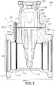
- a subassembly 100 of a body 110, a bonnet 120, and a vein 130 is seen in FIG. 1 .
- the subassembly 100 is incorporated into a gate valve 1000, seen in FIG. 13A .
- the bonnet 120 includes a notch relief 140 into which the vein 130 fits.
- the body 110 defines a fluid bore 145 which is substantially continuous from an inlet end 112 to an outlet end 114 of the body 110 to allow fluid flow therein.
- an interior 210 of the body 110 is substantially continuous and includes the fluid bore 145 and a valve cavity 214 that is defined within the body 110.
- the valve cavity 214 includes a valve seat 215.
- An interior 220 of the bonnet 120 is defined within a cavity 225 of the bonnet 120.
- the cavity 225 of the bonnet 120 is in fluid communication with the valve seat 215 which is then in fluid communication with the fluid bore 145.
- fluid flows from the inlet 112 to the outlet 114.
- the gate valve 1000 incorporating the subassembly 100 includes an encapsulated disc 710 (see FIGs. 7A-7C ) as a selective gate to prevent fluid flow.
- a gasket seat 222 provides space for inclusion of a gasket (not shown) to seal the connection between the bonnet 120 and the body 110.
- the bonnet 120 includes a flange 255 that matches up with the body 110 over the gasket seat 222, where a flange 655 (seen in FIG. 6 ) matches that of the flange 255.
- the flange 255 allows for bolts to secure the bonnet 120 to the body 110.
- the flange 255 ends at an outermost extent 257.
- the flange 655 is readily discerned in FIG. 2 because the cross-sectional view is taken through webbing 235. Webbing 236 is seen on the body 110 one opposite side of the valve cavity 214 from webbing 235.
- the notch 140 of the bonnet 120 aligns with a sensing bore 230 in the webbing 235 of the body 110.
- the sensing bore 230 extends from a flange end 240 of the body 110 down to the fluid bore 145.
- a lay length 250 as measured from the inlet end 112 to the outlet end 114 of the body 110 can also be seen.
- the sensing bore 230 includes an insert portion 310 and a threaded portion 320.
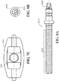
- the vein 130 includes a shank portion 330 and a threaded portion 340.
- the vein 130 defines a bore 350 extending from a shank end 360 of the vein 130 to a thread end 370 of the vein 130 such that the bore 350 is continuous along the entire length of the vein 130.
- the vein 130 is shown with its threaded portion 340 engaging the threaded portion 320 of the sensing bore 230. This interaction secures the vein 130 in place and seals an interior surface 380 of the vein 130 from an exterior surface 390.
- the vein 130 and the sensing bore 230 are cylindrical in the current embodiment, these shapes should not be considered limiting on the scope of the disclosure.
- the vein 130 extends nearly the entire length of the sensing bore 230. Although some unengaged threads are shown along the threaded portion 320, the vein 130 is designed to extend as far as possible into the sensing bore 230.
- the vein 130 is made of brass, stainless steel, copper, plastic, or any other type of material subject to low corrosion in an aqueous environment.
- the body 110 and the bonnet 120 are made of cast iron, although other similar materials may be used in various embodiments. Because cast iron can be highly corrosive when exposed to water, the extension of the vein 130 into the sensing bore 230 prevents corrosion, pitting, and tuberculation from degrading the ability of fluid to flow through the sensing bore 230.
- the body 110 will have a protective coating, but, in some circumstances, such a protective coating may not be applied easily to the interior of the sensing bore 230. However, in some embodiments, no vein 130 will be needed to prevent corrosion because a protective coating may be applied inside the sensing bore 230. In some embodiments, the vein 130 or another vein may be used but may not need to be extended along the entire length of the sensing bore 230.
- the sensing bore 230 is generally cylindrical although the notch 140 is not.
- the notch 140 includes a portion that is semi-cylindrical, but the remainder of the notch 140 extends to the outermost extent 257.
- This configuration of the notch 140 allows for easier assembly of the bonnet 120 onto the body 110 if the vein 130 is already in place.
- the vein 130 may be prefabricated with the body 110 or may be preassembled with the body 110 as provided.
- the subassembly 100 may need to be serviced or the bonnet 120 may need to be replaced due to cracking or other failure.
- Gate valves are designed in sizes ranging from a few centimeters (a few inches) to several meters (several feet) in diameter. Particularly in embodiments with larger diameters, the bonnet 120 may be extremely heavy. Some gate valves are as large as 122 cm (48-inches) in diameter, and 60 cm (24-inch) diameter gate valves each include a bonnet weighing approximately 2,270 kg (5,000 pounds). As such, attempting to align the vein 130 with a bore in the bonnet 120 may be very difficult.
- the notch 140 allows a user assembling the subassembly 100 to place the bonnet 120 onto the body 110 and then slide the bonnet 120 into place with the notch 140 aligned to the vein 130 and the sensing bore 230. However, in some embodiments-particularly in embodiments in which the bonnet 120 is relatively light-the bonnet 120 may include a bore instead of the notch 140 with an open side, as in the current embodiment.
- the placement of the sensing bore 230 and the vein 130 is that the placement does not require an increase in the lay length 250 of the body 110.
- the body 110 can be used with piping systems that are already designed for standard lay lengths such as lay length 250. From time to time, such gate valves will need servicing, either to remove blockages in the line, to repair cracked piping, to repair a non-functioning gate valve, or for other purposes. As such, damage to the vein 130 poses a significant risk.
- Another advantage to the placement of the vein 130 is that it is close to other components of the subassembly 100. As such, the vein 130 may be less-susceptible to movements in the earth whether such movements are seismic or due to assembly, disassembly, and burying of the subassembly 100 in the ground.
- the subassembly 100 is part of the gate valve 1000.
- Pipes in a piping system are typically installed as quickly as possible.
- Gate valves such as gate valve 1000 are typically handled with care because improper installation of gate valves can lead to leaking piping systems and nonfunctioning gate valves.
- sensors such as the pressure sensor-which may be relatively delicate and relatively expensive-are also handled with care if the vein 130 and the pressure sensor are attached to the gate valve 1000 as opposed to another component of the piping system.
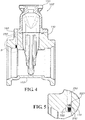
- a subassembly 100' may be substantially the same as subassembly 100.
- the subassembly 100' may be provided with a plug 510 instead of the vein 130 as in subassembly 100.
- Such an embodiment as subassembly 100' may make the use of veins 130 optional.
- one who assembles the piping system may optionally place the vein 130 or another device into the sensing bore 230 in place of the plug 510.
- the plug 510 is threaded to engage the threaded portion 320 of the sensing bore 230.
- the plug 510 includes a hex head 520 and operates similarly to a set screw in the current embodiment.
- a quick-connect adapter may be connected to the sensing bore 230 to allow quick assembly of sensing apparatus.
- the vein 130 or a similar probe may be molded in place inside the body 110 casting. In such embodiments, threaded portions 320,340 may be unnecessary as compression from the cooling of the cast iron most likely will retain the vein 130 in place.
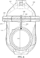
- FIG. 6 shows the subassembly 100 on a plane cut through the axis of the vein 130 orthogonal to the cutting plane in the view of FIG. 2 .
- the flange 655 of the body 110 corresponds with the flange 255 of the bonnet 120.
- the thickness of the webbing 235 can be seen in the view.
- the webbing 235 is various thicknesses.
- the subassembly 100 includes 15 cm (6-inch) fluid bore 145.
- the vein 130 is about 3.81 cm (one-half inch) in external diameter.
- the webbing 235 (and also 236) is about 2.5 cm (one inch) in thickness.
- the sensing bore 230 is located centrally to retain the structural integrity of the webbing 235.
- the webbing 235 may be thicker even if the sensing bore 230 and the vein 130 are not. Thus, in larger size embodiments, placement of the sensing bore 230 is less important. In smaller size embodiments, a smaller vein 130 and sensing bore 230 may be used to accommodate thinner webbing 235.
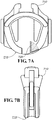
- encapsulated disc 710 can be added to subassembly 100 as part of a gate valve 1000 in accord with one embodiment of the disclosure.
- the encapsulated disc 710 includes a contact surface 715 for contacting and sealing with the valve seat 215 (seen in FIG. 2 ).
- the encapsulated disc 710 is coated in a water-impervious material that aids in sealing the gate valve 1000 when in the closed position.
- the encapsulated disc 710 includes an actuation bore 725.
- the encapsulated disc 710 is actuated by a stem 810 which is seen in FIGs. 8A and 8B .
- the stem 810 includes a threaded portion 815 that interacts with the actuation bore 725.
- the stem 810 also includes a nut portion 820 that can be rotated by the users to actuate the encapsulated disc 710 and to open or to close the gate valve 1000 selectively.
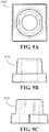
- FIGs. 9A-9C show various views of a disc nut 910 that couples the stem 810 and the encapsulated disc 710.
- FIGs. 10A-10C show various views of a wrench nut 1010 which includes an indicator 1020a,1020b showing the direction of turning to place the gate valve 1000 in an open position.
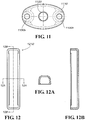
- FIG. 11 shows a top cover 1110.
- the top cover 1110 includes an actuation bore 1120 and two connection bores 1130a,b.
- FIG. 12 shows a guide cap 1210.
- the guide cap 1210 is attached to the side of the encapsulated disc 710 to help prevent friction binding of the encapsulated disc 710 against the body 110.
- the guide cap 1210 is made of plastic in the current embodiment, although other similarly non-binding materials may be used in various embodiments.
- FIG. 12A shows a cross-sectional view of the guide cap taken in a plane indicated by line 12A in FIG. 12
- FIG. 12B shows a cross-sectional view of the guide cap taken in a plane indicated by line 12B in FIG. 12 .
- a gate valve 1000 may incorporate the subassembly 100 along with the encapsulated disc 710 (not shown), the stem 810 (not shown), the disc nut 910 (not shown), the wrench nut 1010, the top cover 1110, and guide caps 1210a,b (not shown).
- a gate valve 1000' may include subassembly 100' as well.
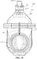
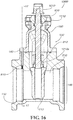
- FIGs. 14 and 15 show cutaway views of the gate valve 1000.
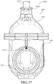
- FIGs. 16 and 17 show cutaway views of the gate valve 1000'.
- each gate valve 1000,1000' When in use, each gate valve 1000,1000' operates as its main function to allow a user selectively to prevent or to allow water flow through the fluid bore 145. Moving the encapsulated disc 710, the gate valve 1000,1000' can be sealed when the contact surface 715 is seated against the valve seat 215. Actuation of the stem 810 moves the encapsulated disc 710 out of the flow path of fluid, thereby opening the flow.
- the sensing bore 230 and the bore 350 of the vein 130 provide a fluid pathway in fluid communication with the interior 210 of the body 110. Because fluid in a piping system is under pressure, fluid is forced through the fluid pathway, and pressure equalizes with the pressure inside the gate valve 1000. As such, a pressure sensor may be placed on the shank end 360 of the vein 130 to sense pressure within the piping system.
- vein 130 may be connected to other types of sensors to sense other aspects of fluid in the system, including (particularly when the fluid is water) turbidity, chlorination, and acidity (pH), among others.
- the vein 130 allows sensors to be placed outside of the gate valve 1000, thereby providing a non-intrusive means of measuring aspects of the fluid in the piping system.
- some sensors may be placed proximate the thread end 370 of the vein 130 or, in some embodiments, may protrude inside the fluid bore 145.
- MEMS microelectromechanical systems
- sensors may be especially adapted for the small spaces of the bore 350.
- gate valves such as gate valve 1000 to be buried 1.83 meters (six feet) or more below the surface of the earth.
- sensors such as the pressure sensor may be read electronically and may include wires leading to the surface.
- the wires may be connected to a remote communicator such as an RF device.
- the RF device will correspond with a mesh network.
- Gate valve 1000' may be provided as a sensor-capable gate valve, such that the vein 130 is not included with the assembly but may be added by the user.
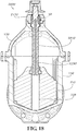
- the gate valve 2000 includes the bonnet 120, the body 110, a stem 2810, and a top cover 2110, among other parts and features.
- the actuation bore 725 extends entirely through the encapsulated disc 710. When the gate valve 2000 is in an open position, the actuation bore 725 is in fluid communication with the interior of the body 110 and with fluid passing therethrough. As such, the actuation bore 725 can be used as testing port.
- the sensing bore 230 is located in the webbing 235.
- such a configuration introduces a machining operation to the casting process of the bonnet 120.
- it is also possible to cast the sensing bore 230 such a casting may be difficult to achieve.
- the sensing bore 230 may weaken the webbing of the bonnet 120 in some applications, which may not be desirable.
- the bonnet 120 is made of cast iron, some steps are typically taken to ensure that the sensing bore 230 does not corrode (as previously described).
- the gate valve 2000 of the current embodiment includes a sensing bore 2230 machined into the stem 2810.
- the sensing bore 2230 is in fluid communication with the actuation bore 725 such that fluid in the body 110 can be communicated up the stem 2810 by fluid pressure in the system for testing.
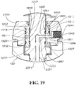
- the sensing bore 2230 includes an axial portion 2231 and a radial portion 2232.
- the radial portion 2232 provides a portion of the testing port from inside the stem 2810 to outside.
- Adjacent the stem 2810 between the top cover 2110 and the bonnet 120 is a bushing 1910.
- the bushing 1910 may be made of various materials including plastic, metal, and composite, among others. In the current embodiment, the bushing 1910 is annular, and many of the features as shown are annular as well.
- the bushing 1910 of the current embodiment includes three annular gasket seating grooves 1912,1914,1916 into which gaskets 1932,1934,1936 seat to seal the testing port from leakage.
- the stem 2810 includes three annular gasket seating grooves 1913,1915,1917 that provide a sealing interface with gaskets 1933,1935,1937.
- fewer or more gasket seating grooves may be included depending on sealing requirements.
- the number and configuration of gaskets and gasket seating grooves may change from one embodiment to another, as will be understood by one of skill in the art.
- the radial portion 2232 communicates with an external shaft annulus 1920, which is an annulus groove defined in the stem 2810.
- the external shaft annulus 1920 ensures that a line of fluid communication may be made regardless of the orientation of the stem 2810 with respect to the bushing 1910.
- the bushing 1910 includes two radial bores 1925,1927 that connect in fluid communication to the external shaft annulus 1920.
- the radial bores 1925,1927 are in fluid communication with an external bushing annulus 1930 which is similar to the external shaft annulus 1920 and substantially connects the two radial bores 1925,1927 along the outside of the bushing 1910.
- the adapter bore 1940 includes a neck portion 1942 and a threaded portion 1944 in the current embodiment, although the adapter bore 1940 need not include any specific connection configuration in all embodiments.
- a sensing mechanism may be connected to the adapter bore 1940 and in fluid communication with the interior of the gate valve 2000.
- the gate valve 2000 may include a plug (not shown) connected in the adapter bore 1940 if the testing port is not in use.
- use of the testing port of the current embodiment includes the actuation bore 725, the sensing bore 2230, external shaft annulus 1920, the two radial bores 1925,1927, external bushing annulus 1930, and the adapter bore 1940.
- the gate valve 2000 may include the sensing mechanism connected in the adapter bore 1940.
- the gate valve 2000 may include a vein such as vein 130 of prior embodiments to connect to a sensing mechanism.
- Locating the sensing bore 2230 in the stem 2810 addresses many of the concerns noted with respect to prior embodiments. Because the sensing bore 2230 is not defined in the bonnet 120, it does not require a machining operation in addition to casting. Moreover, the bonnet 120 is not weakened by the inclusion of sensing bore 230, which may be a concern in some embodiments. Further, because the stem 2810 is exposed to water throughout its life, it is typically made of a material that is substantially corrosion-resistant or subjected to a process to discourage corrosion. As such, no additional steps are required to protect the sensing bore 2230 from corrosion as would be required in prior embodiments. Further, the stem 2810 may be machined in some embodiments, and adding a machining step to include the sensing bore 2230 would not introduce excessive costs for additional machinery or capital into the process of manufacturing the stem 2810.
- the gate valve 2000 is normally in an open position with the gate 710 raised (not shown in FIGs. 18 and 19 ).
- the actuation bore 725 is in fluid communication with the interior of the gate valve 2000, and, as such, is exposed to fluid pressure in the piping system.
- the fluid pressure in the piping system allows fluid flow into the axial portion 2231 of the sensing bore 2230 and then into the radial portion 2232. Fluid exits the radial portion 2232 and travels into the external shaft annulus 1920, into the two radial bores 1925,1927, into the external bushing annulus 1930, into the neck portion 1942 of the adapter bore 1940, and then into the threaded portion 1944 of the adapter bore 1940.
- the fluid in the threaded portion 1944 is then communicated into the sensing mechanism which may be capable of sensing various aspects of the fluid system, including pressure, turbidity, chlorination, and acidity (pH), among others.
- the gate valve 2000 may be changed to a closed position.
- the actuation bore 725 is not in fluid communication with the interior of the gate valve 2000.
- the gate valve 2000 should be in the closed position only when maintenance or faults are determined in the piping system, and, as such, use of the sensing mechanism may not be required when the gate valve 2000 is in the closed position.
- the gate 710 may include a sensing bore (not shown) to communicate fluid from one side of the gate 710 into the actuation bore 725 and maintain the ability to test at least one part of the piping system when the gate valve 2000 is in the closed position.
- conditional language such as, among others, "can,” “could,” “might,” or “may,” unless specifically stated otherwise, or otherwise understood within the context as used, is generally intended to convey that certain embodiments include, while alternative embodiments do not include, certain features, elements and/or steps. Thus, such conditional language is not generally intended to imply that features, elements and/or steps are in any way required for one or more particular embodiments or that one or more particular embodiments necessarily include logic for deciding, with or without user input or prompting, whether these features, elements and/or steps are included or are to be performed in any particular embodiment.
Landscapes
- Engineering & Computer Science (AREA)
- General Engineering & Computer Science (AREA)
- Mechanical Engineering (AREA)
- Health & Medical Sciences (AREA)
- Life Sciences & Earth Sciences (AREA)
- Chemical & Material Sciences (AREA)
- Food Science & Technology (AREA)
- Medicinal Chemistry (AREA)
- Physics & Mathematics (AREA)
- Analytical Chemistry (AREA)
- Biochemistry (AREA)
- General Health & Medical Sciences (AREA)
- General Physics & Mathematics (AREA)
- Immunology (AREA)
- Pathology (AREA)
- Indication Of The Valve Opening Or Closing Status (AREA)
Claims (8)
- Ein Schieberventil, das die folgenden Merkmale aufweist:einen Ventilkörper (110); undeine Fühlbohrung (230), die in dem Schieberventil ausgebildet ist, eine Haube (120), wobei eine Entlastungskerbe (140) in der Haube (120) ausgebildet ist, und wobei die Fühlbohrung (230) durch die Entlastungskerbe (120) der Haube (120) hindurch erreichbar ist;ein Venenröhrchen (130), wobei ein Durchmesser des Venenröhrchens (130) ungefähr gleich einem Durchmesser der Fühlbohrung (230) ist, wobei die Fühlbohrung (230) Gewinde aufweist und wobei das Venenröhrchen (130) Gewinde aufweist, das mit dem Gewinde der Fühlbohrung (230) zusammenpasst; und
wobei das Venenröhrchen (130) sich durch die Haube (120) erstreckt, gekennzeichnet dadurch, dass
die Fühlbohrung (230) zentral in einem Netzwerk (235) des Ventilkörpers (110) ausgebildet ist, wobei die Haube (120) einen Flansch (255) mit einem äußersten Umfang (257) enthält, und worin der Ventilkörper (110) einen Flansch (655) enthält, der mit dem Flansch (255) der Haube (120) über einen Dichtungssitz (222) zusammenpasst, und wobei die Kerbe (140) sich bis zu dem äußersten Umfang (257) des Flansches (255) erstreckt. - Eine Unteranordnung, die die folgenden Merkmale aufweist:Einen Körper (110), wobei der Körper (110) eine Fühlbohrung (230) ausbildet;eine Haube (120), die den Körper (120) berührt; undwenigstens eines von einem Venenröhrchen (130) und einem Stöpsel (510) in der Fühlbohrung, wobei eine Entlastungskerbe (140) in der Haube (130) ausgebildet ist, und wobei die Fühlbohrung (230) durch die Entlastungskerbe (140) der Haube (130) erreichbar ist, gekennzeichnet dadurch, dass die Fühlbohrung (230) zentral in einem Netzwerk (235) des Körpers (110) ausgebildet ist,und wobei die Haube (120) einen Flansch (255) mit einem äußersten Umfang (257) enthält, und wobei der Körper (110) einen Flansch (655) enthält, der mit dem Flansch (255) der Haube (120) über einen Dichtungssitz (222) zusammenpasst, und wobei die Kerbe (140) sich zu dem äußersten Umfang (257) des Flansches (255) erstreckt.
- Die Unteranordnung von Anspruch 2, wobei sich das Venenröhrchen (130) durch die Entlastungskerbe (140) in der Haube (120) erstreckt.
- Ein Verfahren zum Erfassen eines Aspekts eines Wasserkontrollsystems, wobei das Verfahren aufweist:Verschaffung eines Zugangs zu dem Wasserkontrollsystem durch eine Zugangsbohrung in einem Schieberventil (1000, 1000`); undzumindest zeitweise Entfernung von Wasser aus der Zugangsbohrung zum Testen; und Erfassung eines Aspekts des entfernten Wassers, wobei die Verschaffung des Zugangs zu dem Wasserkontrollsystem ein Erreichen der Zugangsbohrung durch eine Entlastungskerbe (140), die in einer Haube (120) des Schieberventils (1000, 1000') ausgebildet ist, umfasst, und wobei die Fühlbohrung (230) zentral in einem Netzwerk (235) des Körpers (110) ausgebildet ist, und wobei die Haube (120) einen Flansch (255) mit einem äußersten Umfang (257) aufweist, und wobei der Körper (110) einen Flansch (655) aufweist, der mit dem Flansch (255) der Haube (120) über einen Dichtungssitz (222) zusammenpasst, und wobei die Kerbe (140) sich zu dem äußersten Umfang (257) des Flansches (255) erstreckt.
- Das Verfahren nach Anspruch 4, wobei das Erlangen von Zugang zu dem Wasserkontrollsystem durch die Zugangsbohrung in dem Schieberventil (1000) ein Erlangen eines Zugangs zu dem Wasserkontrollsystem durch ein Venenröhrchen (130) aufweist, das sich durch die Zugangsbohrung erstreckt.
- Ein Schieberventil, das aufweist:einen Körper (110);einen Schaft (2810);eine Fühlbohrung (2230), die in dem Schaft (2810) ausgebildet ist;eine obere Abdeckung (2110), wobei die obere Abdeckung (2110) eine Adapterbohrung (1940) ausbildet, und wobei die Adapterbohrung (1940) in fluider Kommnunikation mit der Fühlbohrung (2230) des Schafts (2810) ist; undeine Buchse (1910), die zwischen dem Schaft (2810) und der oberen Abdeckung (2110) angeordnet ist, wobei die Buchse (1910) wenigstens eine radiale Bohrung (1925, 1927) ausbildet, und einen äußeren Buchsenring (1930), wobei die Fühlbohrung (2230) einen axialen Bereich (2231) und einen radialen Bereich (2232) enthält, wobei der Schaft (2810) weiterhin einen äußeren Schaftring (1920) ausbildet, wobei der äußere Buchsenring (1930), der äußere Schaftring (1920), die Fühlbohrung (2230) und die Adapterbohrung (1940) in fluider Kommunikation miteinander sind,wobei das Schieberventil (2000) weiterhin ein Schiebetor (710) aufweist, wobei das Schiebetor (710) eine Betätigungsbohrung (725) ausbildet, wobei der Schaft (2810) mit der Betätigungsbohrung (725) zusammenwirkt, wobei die Betätigungsbohrung (725) in fluider Kommunikation mit der Fühlbohrung (2230) ist, und wobei die Buchse (1910) mindestens zwei ringförmige Dichtungssitznuten (1912, 1914, 1916) enthält, in denen Dichtungen (1932, 1934, 1936) sitzen, um einen Testzugang gegen Undichtigkeit abzudichten, und wobei der Schaft (2810) mindestens zwei Dichtungssitznuten (1913, 1915, 1917) enthält, die einen Dichtungsschnittstelle zu den Dichtungen (1933, 1935, 1937) bereitstellen, und wobei der Schaft (2810) einen Schaftring (1920) ausbildet, so dass die Fühlbohrung (2230), der Schaftring (1920), die radiale Bohrung (1925, 1927), der Buchsenring (1930) und die Adapterbohrung (1940) einen Durchflussweg ausbilden, so dass eine Verbindungslinie fluider Kommunikation gebildet werden kann, und zwar unabhängig von der Orientierung des Schafts (2810) in Bezug auf die Buchse (1910).
- Ein Verfahren zum Erfassen eines Aspekts eines Wasserkontrollsystems, wobei das Verfahren aufweist:Verschaffen eines Zugangs zu dem Wasserkontrollsystem durch eine Fühlbohrung (2230), die in einem Schaft (2810) eines Schieberventils ausgebildet ist;zumindest zeitweises Entfernen von Wasser aus der Fühlbohrung (2230) zum Testen; und Erfassen eines Aspekts des entfernten Wassers, wobei das zumindest zeitweise Entfernen des Wassers aus der Fühlbohrung (2230) zum Testen das Entfernen von Wasser durch eine Adapterbohrung (1940) beinhaltet, die in der oberen Abdeckung (2110) des Schieberventils ausgebildet ist,wobei eine Buchse (1910) zwischen dem Schaft (2810) und der oberen Abdeckung (2110) positioniert ist, wobei die Buchse (1910) zumindest eine radiale Bohrung (1925, 1927) und einen Buchsenring (1930) ausbildet, wobei die Fühlbohrung (2230) einen axialen Bereich (2231) und einen radialen Bereich (2232) enthält, wobei der Schaft (2810) weiterhin einen äußeren Schaftring (1920) ausbildet und wobei die Buchse (1910) einen äußeren Buchsenring (1930) ausbildet, wobei der äußere Buchsenring (1930), der äußere Schaftring (1920), die Fühlbohrung (2230) und die Adapterbohrung (1940) untereinander in fluider Kommunikation sind, wobei das Verschaffen von Zugang zu dem Wasserkontrollsystem durch die Fühlbohrung ein Verschaffen eines Zugangs zu dem Wasserkontrollsystem durch eine Betätigungsbohrung eines Schiebetors beinhaltet, wobei die Betätigungsbohrung mit der Fühlbohrung wechselwirkt und wobei die Buchse (1910) mindestens zwei ringförmige Dichtungssitznuten (1912, 1914, 1916) enthält, in denen Dichtungen (1932, 1934, 1936) sitzen, um die Testöffnung gegen Undichtigkeit abzudichten, und wobei der Schaft (2810) zumindest zwei ringförmige Dichtungssitznuten (1913, 1915, 1917) enthält, die eine Dichtungsschnittstelle mit Dichtungen (1933, 1935, 1937) bereitstellen, und wobei der Schaft (2810) einen Schaftring (1920) ausbildet, so dass die Fühlbohrung (1930), der Schaftring (1920), die radiale Bohrung (1925, 1927), der Dichtring (1930) und die Adapterbohrung (1940) einen Durchflussweg definieren, so dass eine Linie fluider Kommunikation gebildet werden kann, und zwar unabhängig von der Orientierung des Schafts (2810) in Bezug auf die Buchse (1910).
- Das Verfahren nach Anspruch 7,
wobei der erfasste Aspekt zumindest eines von Druck, Turbulenz, Chlorierung und Säuregrad enthält.
Applications Claiming Priority (5)
| Application Number | Priority Date | Filing Date | Title |
|---|---|---|---|
| US201261592321P | 2012-01-30 | 2012-01-30 | |
| US201261643400P | 2012-05-07 | 2012-05-07 | |
| US13/753,431 US9032781B2 (en) | 2012-01-30 | 2013-01-29 | Sensor-enabled gate valve |
| US13/753,428 US9021867B2 (en) | 2012-01-30 | 2013-01-29 | Sensor-enabled gate valve |
| PCT/US2013/023755 WO2013116276A1 (en) | 2012-01-30 | 2013-01-30 | Sensor-enabled gate valve |
Publications (3)
| Publication Number | Publication Date |
|---|---|
| EP2809975A1 EP2809975A1 (de) | 2014-12-10 |
| EP2809975A4 EP2809975A4 (de) | 2015-10-21 |
| EP2809975B1 true EP2809975B1 (de) | 2016-12-28 |
Family
ID=48869099
Family Applications (1)
| Application Number | Title | Priority Date | Filing Date |
|---|---|---|---|
| EP13743385.0A Active EP2809975B1 (de) | 2012-01-30 | 2013-01-30 | Sensoraktivierutes schieberventil |
Country Status (10)
| Country | Link |
|---|---|
| US (3) | US9032781B2 (de) |
| EP (1) | EP2809975B1 (de) |
| CN (4) | CN106907522B (de) |
| AU (4) | AU2013215321B2 (de) |
| CA (1) | CA2858845C (de) |
| GB (3) | GB201903206D0 (de) |
| IL (3) | IL233065A (de) |
| MX (2) | MX357795B (de) |
| SG (2) | SG10201605268WA (de) |
| WO (1) | WO2013116276A1 (de) |
Cited By (1)
| Publication number | Priority date | Publication date | Assignee | Title |
|---|---|---|---|---|
| US20230304622A1 (en) * | 2020-08-14 | 2023-09-28 | Pipe Transformations Ltd | Improvements in pipeline networks |
Families Citing this family (6)
| Publication number | Priority date | Publication date | Assignee | Title |
|---|---|---|---|---|
| US9021867B2 (en) | 2012-01-30 | 2015-05-05 | Mueller International, Llc | Sensor-enabled gate valve |
| US9032781B2 (en) | 2012-01-30 | 2015-05-19 | Mueller International, Llc | Sensor-enabled gate valve |
| US11988656B2 (en) | 2015-09-21 | 2024-05-21 | Mcwane, Inc. | Remote monitoring of water distribution system |
| US10317384B2 (en) | 2015-09-21 | 2019-06-11 | AMI Investments, L.L.C. | Remote monitoring of water distribution system |
| US11174958B2 (en) | 2019-01-24 | 2021-11-16 | Jet Oilfield Services, LLC | Gate valve and method of repairing same |
| US11009149B2 (en) | 2019-04-19 | 2021-05-18 | Mueller International, Llc | Bonnet and stuffing box assembly |
Family Cites Families (17)
| Publication number | Priority date | Publication date | Assignee | Title |
|---|---|---|---|---|
| US4026517A (en) * | 1976-03-17 | 1977-05-31 | New Concepts, Inc. | Biasable seal for gate valves |
| US4696325A (en) | 1984-07-18 | 1987-09-29 | Magee Anthony J | Sensing of fire installation water valves being closed |
| US4968002A (en) | 1989-05-03 | 1990-11-06 | American Cast Iron Pipe Company | Boltless bonnet assembly for gate valve |
| US5056758A (en) | 1990-05-11 | 1991-10-15 | Bramblet John W | Valve stem packing structure |
| DE4328879A1 (de) * | 1993-08-27 | 1995-03-02 | Ebro Armaturen Gebr Broeer Gmb | Absperrarmatur |
| US5616829A (en) | 1995-03-09 | 1997-04-01 | Teledyne Industries Inc. | Abnormality detection/suppression system for a valve apparatus |
| US5728942A (en) | 1995-11-28 | 1998-03-17 | Boger; Henry W. | Fluid pressure measuring system for control valves |
| FR2764360B1 (fr) * | 1997-06-06 | 1999-09-17 | Sarl Mirr Maintenance Ind Et R | Robinet equipe d'un passage d'acces a son volume interne |
| US6338359B1 (en) * | 1998-02-19 | 2002-01-15 | Welker Engineering Company | Dual automatic insertion device |
| US6240789B1 (en) | 1998-05-15 | 2001-06-05 | Crane Nuclear, Inc. | Permanently instrumented actuated valve assembly, with internally-gauged, permanently instrumented shaft |
| GB2350412A (en) | 1999-05-22 | 2000-11-29 | Robert Peter Enston | Freeing of seized valves |
| US6557577B1 (en) | 2001-06-19 | 2003-05-06 | Cor-Val, Inc. | Threaded union safety device and method |
| KR100887180B1 (ko) * | 2007-09-28 | 2009-03-09 | 주식회사 코펙스 | 오토 크린넷 설비용 쓰레기 배출 밸브 |
| KR100944701B1 (ko) * | 2009-08-31 | 2010-03-02 | (주) 삼진정밀 | 유수감지용 제수밸브 |
| CN101900211B (zh) * | 2010-08-12 | 2012-08-29 | 承德江钻石油机械有限责任公司 | 一种气动平行闸板阀 |
| US9021867B2 (en) | 2012-01-30 | 2015-05-05 | Mueller International, Llc | Sensor-enabled gate valve |
| US9032781B2 (en) | 2012-01-30 | 2015-05-19 | Mueller International, Llc | Sensor-enabled gate valve |
-
2013
- 2013-01-29 US US13/753,431 patent/US9032781B2/en active Active
- 2013-01-30 AU AU2013215321A patent/AU2013215321B2/en active Active
- 2013-01-30 GB GBGB1903206.9A patent/GB201903206D0/en not_active Ceased
- 2013-01-30 MX MX2017012369A patent/MX357795B/es unknown
- 2013-01-30 CN CN201710131534.1A patent/CN106907522B/zh active Active
- 2013-01-30 MX MX2014007571A patent/MX352303B/es active IP Right Grant
- 2013-01-30 CN CN201810359905.6A patent/CN108612855B/zh active Active
- 2013-01-30 SG SG10201605268WA patent/SG10201605268WA/en unknown
- 2013-01-30 EP EP13743385.0A patent/EP2809975B1/de active Active
- 2013-01-30 GB GB1410234.7A patent/GB2511014B/en active Active
- 2013-01-30 CN CN201380018687.5A patent/CN104395656B/zh active Active
- 2013-01-30 CN CN201810360409.2A patent/CN108468818B/zh active Active
- 2013-01-30 CA CA2858845A patent/CA2858845C/en active Active
- 2013-01-30 WO PCT/US2013/023755 patent/WO2013116276A1/en not_active Ceased
- 2013-01-30 GB GB1904294.4A patent/GB2569479B/en active Active
- 2013-01-30 SG SG11201403056RA patent/SG11201403056RA/en unknown
-
2014
- 2014-06-10 IL IL233065A patent/IL233065A/en active IP Right Grant
-
2015
- 2015-04-15 US US14/687,181 patent/US9534694B2/en active Active
-
2016
- 2016-11-20 IL IL249059A patent/IL249059A/en active IP Right Grant
- 2016-11-22 US US15/358,683 patent/US9939069B2/en active Active
-
2017
- 2017-03-16 IL IL251235A patent/IL251235A/en active IP Right Grant
- 2017-06-22 AU AU2017204244A patent/AU2017204244B2/en active Active
-
2018
- 2018-12-13 AU AU2018278989A patent/AU2018278989B2/en active Active
- 2018-12-13 AU AU2018278985A patent/AU2018278985B2/en active Active
Non-Patent Citations (1)
| Title |
|---|
| None * |
Cited By (1)
| Publication number | Priority date | Publication date | Assignee | Title |
|---|---|---|---|---|
| US20230304622A1 (en) * | 2020-08-14 | 2023-09-28 | Pipe Transformations Ltd | Improvements in pipeline networks |
Also Published As
Similar Documents
| Publication | Publication Date | Title |
|---|---|---|
| AU2018278989B2 (en) | Sensor-enabled gate valve | |
| US8584705B2 (en) | Bidirectional sleeved/plug ball check valve | |
| US8522630B1 (en) | System for retrieving a fluid sample from a fluid sample source | |
| EP2914887B1 (de) | Isolierventilanordnung | |
| WO2011019808A1 (en) | Speed control drive section with failsafe valve | |
| US9021867B2 (en) | Sensor-enabled gate valve | |
| EP2633211B1 (de) | Ausgleichsventil | |
| US20090056438A1 (en) | Gage Cock Ball Valve | |
| AU2005218073B2 (en) | Pipe insert | |
| JP2013527404A (ja) | ブラインドフランジ型バルブを有するバルブ装置 | |
| CA3206356A1 (en) | Butterfly check valve | |
| WO2015122798A1 (ru) | Трубопроводный обратный клапан | |
| TWM453065U (zh) | 閥用的保護裝置 | |
| GB2476129A (en) | Drain off valve |
Legal Events
| Date | Code | Title | Description |
|---|---|---|---|
| PUAI | Public reference made under article 153(3) epc to a published international application that has entered the european phase |
Free format text: ORIGINAL CODE: 0009012 |
|
| 17P | Request for examination filed |
Effective date: 20140901 |
|
| AK | Designated contracting states |
Kind code of ref document: A1 Designated state(s): AL AT BE BG CH CY CZ DE DK EE ES FI FR GB GR HR HU IE IS IT LI LT LU LV MC MK MT NL NO PL PT RO RS SE SI SK SM TR |
|
| AX | Request for extension of the european patent |
Extension state: BA ME |
|
| DAX | Request for extension of the european patent (deleted) | ||
| RA4 | Supplementary search report drawn up and despatched (corrected) |
Effective date: 20150922 |
|
| RIC1 | Information provided on ipc code assigned before grant |
Ipc: F16K 37/00 20060101ALI20150916BHEP Ipc: F16K 3/316 20060101ALI20150916BHEP Ipc: F16K 3/314 20060101ALI20150916BHEP Ipc: F16K 3/00 20060101AFI20150916BHEP |
|
| RIC1 | Information provided on ipc code assigned before grant |
Ipc: F16K 37/00 20060101ALI20160609BHEP Ipc: F16K 3/00 20060101AFI20160609BHEP Ipc: F16K 3/316 20060101ALI20160609BHEP Ipc: F16K 3/314 20060101ALI20160609BHEP |
|
| GRAP | Despatch of communication of intention to grant a patent |
Free format text: ORIGINAL CODE: EPIDOSNIGR1 |
|
| INTG | Intention to grant announced |
Effective date: 20160804 |
|
| GRAS | Grant fee paid |
Free format text: ORIGINAL CODE: EPIDOSNIGR3 |
|
| STAA | Information on the status of an ep patent application or granted ep patent |
Free format text: STATUS: GRANT OF PATENT IS INTENDED |
|
| GRAA | (expected) grant |
Free format text: ORIGINAL CODE: 0009210 |
|
| STAA | Information on the status of an ep patent application or granted ep patent |
Free format text: STATUS: THE PATENT HAS BEEN GRANTED |
|
| AK | Designated contracting states |
Kind code of ref document: B1 Designated state(s): AL AT BE BG CH CY CZ DE DK EE ES FI FR GB GR HR HU IE IS IT LI LT LU LV MC MK MT NL NO PL PT RO RS SE SI SK SM TR |
|
| REG | Reference to a national code |
Ref country code: GB Ref legal event code: FG4D |
|
| REG | Reference to a national code |
Ref country code: CH Ref legal event code: EP |
|
| REG | Reference to a national code |
Ref country code: AT Ref legal event code: REF Ref document number: 857601 Country of ref document: AT Kind code of ref document: T Effective date: 20170115 |
|
| REG | Reference to a national code |
Ref country code: IE Ref legal event code: FG4D |
|
| REG | Reference to a national code |
Ref country code: DE Ref legal event code: R096 Ref document number: 602013015898 Country of ref document: DE |
|
| REG | Reference to a national code |
Ref country code: FR Ref legal event code: PLFP Year of fee payment: 5 |
|
| PG25 | Lapsed in a contracting state [announced via postgrant information from national office to epo] |
Ref country code: LV Free format text: LAPSE BECAUSE OF FAILURE TO SUBMIT A TRANSLATION OF THE DESCRIPTION OR TO PAY THE FEE WITHIN THE PRESCRIBED TIME-LIMIT Effective date: 20161228 |
|
| REG | Reference to a national code |
Ref country code: LT Ref legal event code: MG4D |
|
| PG25 | Lapsed in a contracting state [announced via postgrant information from national office to epo] |
Ref country code: NO Free format text: LAPSE BECAUSE OF FAILURE TO SUBMIT A TRANSLATION OF THE DESCRIPTION OR TO PAY THE FEE WITHIN THE PRESCRIBED TIME-LIMIT Effective date: 20170328 Ref country code: LT Free format text: LAPSE BECAUSE OF FAILURE TO SUBMIT A TRANSLATION OF THE DESCRIPTION OR TO PAY THE FEE WITHIN THE PRESCRIBED TIME-LIMIT Effective date: 20161228 Ref country code: GR Free format text: LAPSE BECAUSE OF FAILURE TO SUBMIT A TRANSLATION OF THE DESCRIPTION OR TO PAY THE FEE WITHIN THE PRESCRIBED TIME-LIMIT Effective date: 20170329 Ref country code: SE Free format text: LAPSE BECAUSE OF FAILURE TO SUBMIT A TRANSLATION OF THE DESCRIPTION OR TO PAY THE FEE WITHIN THE PRESCRIBED TIME-LIMIT Effective date: 20161228 |
|
| REG | Reference to a national code |
Ref country code: NL Ref legal event code: MP Effective date: 20161228 |
|
| REG | Reference to a national code |
Ref country code: AT Ref legal event code: MK05 Ref document number: 857601 Country of ref document: AT Kind code of ref document: T Effective date: 20161228 |
|
| PG25 | Lapsed in a contracting state [announced via postgrant information from national office to epo] |
Ref country code: RS Free format text: LAPSE BECAUSE OF FAILURE TO SUBMIT A TRANSLATION OF THE DESCRIPTION OR TO PAY THE FEE WITHIN THE PRESCRIBED TIME-LIMIT Effective date: 20161228 Ref country code: FI Free format text: LAPSE BECAUSE OF FAILURE TO SUBMIT A TRANSLATION OF THE DESCRIPTION OR TO PAY THE FEE WITHIN THE PRESCRIBED TIME-LIMIT Effective date: 20161228 Ref country code: BE Free format text: LAPSE BECAUSE OF NON-PAYMENT OF DUE FEES Effective date: 20170131 Ref country code: HR Free format text: LAPSE BECAUSE OF FAILURE TO SUBMIT A TRANSLATION OF THE DESCRIPTION OR TO PAY THE FEE WITHIN THE PRESCRIBED TIME-LIMIT Effective date: 20161228 |
|
| PG25 | Lapsed in a contracting state [announced via postgrant information from national office to epo] |
Ref country code: NL Free format text: LAPSE BECAUSE OF FAILURE TO SUBMIT A TRANSLATION OF THE DESCRIPTION OR TO PAY THE FEE WITHIN THE PRESCRIBED TIME-LIMIT Effective date: 20161228 |
|
| PG25 | Lapsed in a contracting state [announced via postgrant information from national office to epo] |
Ref country code: CZ Free format text: LAPSE BECAUSE OF FAILURE TO SUBMIT A TRANSLATION OF THE DESCRIPTION OR TO PAY THE FEE WITHIN THE PRESCRIBED TIME-LIMIT Effective date: 20161228 Ref country code: IS Free format text: LAPSE BECAUSE OF FAILURE TO SUBMIT A TRANSLATION OF THE DESCRIPTION OR TO PAY THE FEE WITHIN THE PRESCRIBED TIME-LIMIT Effective date: 20170428 Ref country code: RO Free format text: LAPSE BECAUSE OF FAILURE TO SUBMIT A TRANSLATION OF THE DESCRIPTION OR TO PAY THE FEE WITHIN THE PRESCRIBED TIME-LIMIT Effective date: 20161228 Ref country code: SK Free format text: LAPSE BECAUSE OF FAILURE TO SUBMIT A TRANSLATION OF THE DESCRIPTION OR TO PAY THE FEE WITHIN THE PRESCRIBED TIME-LIMIT Effective date: 20161228 Ref country code: EE Free format text: LAPSE BECAUSE OF FAILURE TO SUBMIT A TRANSLATION OF THE DESCRIPTION OR TO PAY THE FEE WITHIN THE PRESCRIBED TIME-LIMIT Effective date: 20161228 |
|
| PG25 | Lapsed in a contracting state [announced via postgrant information from national office to epo] |
Ref country code: PT Free format text: LAPSE BECAUSE OF FAILURE TO SUBMIT A TRANSLATION OF THE DESCRIPTION OR TO PAY THE FEE WITHIN THE PRESCRIBED TIME-LIMIT Effective date: 20170428 Ref country code: AT Free format text: LAPSE BECAUSE OF FAILURE TO SUBMIT A TRANSLATION OF THE DESCRIPTION OR TO PAY THE FEE WITHIN THE PRESCRIBED TIME-LIMIT Effective date: 20161228 Ref country code: BE Free format text: LAPSE BECAUSE OF FAILURE TO SUBMIT A TRANSLATION OF THE DESCRIPTION OR TO PAY THE FEE WITHIN THE PRESCRIBED TIME-LIMIT Effective date: 20161228 Ref country code: ES Free format text: LAPSE BECAUSE OF FAILURE TO SUBMIT A TRANSLATION OF THE DESCRIPTION OR TO PAY THE FEE WITHIN THE PRESCRIBED TIME-LIMIT Effective date: 20161228 Ref country code: PL Free format text: LAPSE BECAUSE OF FAILURE TO SUBMIT A TRANSLATION OF THE DESCRIPTION OR TO PAY THE FEE WITHIN THE PRESCRIBED TIME-LIMIT Effective date: 20161228 Ref country code: IT Free format text: LAPSE BECAUSE OF FAILURE TO SUBMIT A TRANSLATION OF THE DESCRIPTION OR TO PAY THE FEE WITHIN THE PRESCRIBED TIME-LIMIT Effective date: 20161228 Ref country code: SM Free format text: LAPSE BECAUSE OF FAILURE TO SUBMIT A TRANSLATION OF THE DESCRIPTION OR TO PAY THE FEE WITHIN THE PRESCRIBED TIME-LIMIT Effective date: 20161228 Ref country code: BG Free format text: LAPSE BECAUSE OF FAILURE TO SUBMIT A TRANSLATION OF THE DESCRIPTION OR TO PAY THE FEE WITHIN THE PRESCRIBED TIME-LIMIT Effective date: 20170328 |
|
| REG | Reference to a national code |
Ref country code: CH Ref legal event code: PL |
|
| PG25 | Lapsed in a contracting state [announced via postgrant information from national office to epo] |
Ref country code: MC Free format text: LAPSE BECAUSE OF FAILURE TO SUBMIT A TRANSLATION OF THE DESCRIPTION OR TO PAY THE FEE WITHIN THE PRESCRIBED TIME-LIMIT Effective date: 20161228 |
|
| REG | Reference to a national code |
Ref country code: DE Ref legal event code: R097 Ref document number: 602013015898 Country of ref document: DE |
|
| PG25 | Lapsed in a contracting state [announced via postgrant information from national office to epo] |
Ref country code: LI Free format text: LAPSE BECAUSE OF NON-PAYMENT OF DUE FEES Effective date: 20170131 Ref country code: CH Free format text: LAPSE BECAUSE OF NON-PAYMENT OF DUE FEES Effective date: 20170131 |
|
| REG | Reference to a national code |
Ref country code: IE Ref legal event code: MM4A |
|
| PLBE | No opposition filed within time limit |
Free format text: ORIGINAL CODE: 0009261 |
|
| STAA | Information on the status of an ep patent application or granted ep patent |
Free format text: STATUS: NO OPPOSITION FILED WITHIN TIME LIMIT |
|
| PG25 | Lapsed in a contracting state [announced via postgrant information from national office to epo] |
Ref country code: LU Free format text: LAPSE BECAUSE OF NON-PAYMENT OF DUE FEES Effective date: 20170130 Ref country code: DK Free format text: LAPSE BECAUSE OF FAILURE TO SUBMIT A TRANSLATION OF THE DESCRIPTION OR TO PAY THE FEE WITHIN THE PRESCRIBED TIME-LIMIT Effective date: 20161228 |
|
| 26N | No opposition filed |
Effective date: 20170929 |
|
| REG | Reference to a national code |
Ref country code: FR Ref legal event code: PLFP Year of fee payment: 6 |
|
| PG25 | Lapsed in a contracting state [announced via postgrant information from national office to epo] |
Ref country code: IE Free format text: LAPSE BECAUSE OF NON-PAYMENT OF DUE FEES Effective date: 20170130 Ref country code: SI Free format text: LAPSE BECAUSE OF FAILURE TO SUBMIT A TRANSLATION OF THE DESCRIPTION OR TO PAY THE FEE WITHIN THE PRESCRIBED TIME-LIMIT Effective date: 20161228 |
|
| PG25 | Lapsed in a contracting state [announced via postgrant information from national office to epo] |
Ref country code: MT Free format text: LAPSE BECAUSE OF NON-PAYMENT OF DUE FEES Effective date: 20170130 |
|
| PG25 | Lapsed in a contracting state [announced via postgrant information from national office to epo] |
Ref country code: HU Free format text: LAPSE BECAUSE OF FAILURE TO SUBMIT A TRANSLATION OF THE DESCRIPTION OR TO PAY THE FEE WITHIN THE PRESCRIBED TIME-LIMIT; INVALID AB INITIO Effective date: 20130130 |
|
| PG25 | Lapsed in a contracting state [announced via postgrant information from national office to epo] |
Ref country code: CY Free format text: LAPSE BECAUSE OF FAILURE TO SUBMIT A TRANSLATION OF THE DESCRIPTION OR TO PAY THE FEE WITHIN THE PRESCRIBED TIME-LIMIT Effective date: 20161228 |
|
| PG25 | Lapsed in a contracting state [announced via postgrant information from national office to epo] |
Ref country code: MK Free format text: LAPSE BECAUSE OF FAILURE TO SUBMIT A TRANSLATION OF THE DESCRIPTION OR TO PAY THE FEE WITHIN THE PRESCRIBED TIME-LIMIT Effective date: 20161228 |
|
| PG25 | Lapsed in a contracting state [announced via postgrant information from national office to epo] |
Ref country code: TR Free format text: LAPSE BECAUSE OF FAILURE TO SUBMIT A TRANSLATION OF THE DESCRIPTION OR TO PAY THE FEE WITHIN THE PRESCRIBED TIME-LIMIT Effective date: 20161228 |
|
| PG25 | Lapsed in a contracting state [announced via postgrant information from national office to epo] |
Ref country code: AL Free format text: LAPSE BECAUSE OF FAILURE TO SUBMIT A TRANSLATION OF THE DESCRIPTION OR TO PAY THE FEE WITHIN THE PRESCRIBED TIME-LIMIT Effective date: 20161228 |
|
| REG | Reference to a national code |
Ref country code: DE Ref legal event code: R082 Ref document number: 602013015898 Country of ref document: DE Representative=s name: SCHWEIGER, MARTIN, DIPL.-ING. UNIV., DE Ref country code: DE Ref legal event code: R082 Ref document number: 602013015898 Country of ref document: DE Representative=s name: WUNDERLICH & HEIM PATENTANWAELTE PARTNERSCHAFT, DE |
|
| REG | Reference to a national code |
Ref country code: DE Ref legal event code: R082 Ref document number: 602013015898 Country of ref document: DE Representative=s name: WUNDERLICH & HEIM PATENTANWAELTE PARTNERSCHAFT, DE |
|
| PGFP | Annual fee paid to national office [announced via postgrant information from national office to epo] |
Ref country code: DE Payment date: 20250109 Year of fee payment: 13 |
|
| PGFP | Annual fee paid to national office [announced via postgrant information from national office to epo] |
Ref country code: FR Payment date: 20250122 Year of fee payment: 13 |
|
| PGFP | Annual fee paid to national office [announced via postgrant information from national office to epo] |
Ref country code: GB Payment date: 20250102 Year of fee payment: 13 |