EP2809954B1 - Method of repair of wear zones on a rotor mounting the fan of a gas turbine engine - Google Patents
Method of repair of wear zones on a rotor mounting the fan of a gas turbine engine Download PDFInfo
- Publication number
- EP2809954B1 EP2809954B1 EP13706582.7A EP13706582A EP2809954B1 EP 2809954 B1 EP2809954 B1 EP 2809954B1 EP 13706582 A EP13706582 A EP 13706582A EP 2809954 B1 EP2809954 B1 EP 2809954B1
- Authority
- EP
- European Patent Office
- Prior art keywords
- flange
- wear
- stem
- fan
- stress
- Prior art date
- Legal status (The legal status is an assumption and is not a legal conclusion. Google has not performed a legal analysis and makes no representation as to the accuracy of the status listed.)
- Active
Links
- 238000000034 method Methods 0.000 title claims description 17
- 230000008439 repair process Effects 0.000 title description 11
- 238000011144 upstream manufacturing Methods 0.000 claims description 17
- 238000010438 heat treatment Methods 0.000 claims description 6
- 239000002184 metal Substances 0.000 claims description 4
- 229910052751 metal Inorganic materials 0.000 claims description 4
- 230000009467 reduction Effects 0.000 claims description 4
- 230000000670 limiting effect Effects 0.000 claims description 3
- 238000003754 machining Methods 0.000 claims description 2
- 241000237503 Pectinidae Species 0.000 claims 3
- 235000020637 scallop Nutrition 0.000 claims 3
- 238000005480 shot peening Methods 0.000 claims 2
- 241000272165 Charadriidae Species 0.000 description 7
- 230000014759 maintenance of location Effects 0.000 description 5
- IJGRMHOSHXDMSA-UHFFFAOYSA-N Atomic nitrogen Chemical compound N#N IJGRMHOSHXDMSA-UHFFFAOYSA-N 0.000 description 4
- 238000001816 cooling Methods 0.000 description 3
- 238000006073 displacement reaction Methods 0.000 description 3
- 241000920340 Pion Species 0.000 description 2
- 229910001069 Ti alloy Inorganic materials 0.000 description 2
- 230000008901 benefit Effects 0.000 description 2
- 239000007789 gas Substances 0.000 description 2
- 229910000816 inconels 718 Inorganic materials 0.000 description 2
- 230000000977 initiatory effect Effects 0.000 description 2
- 239000007788 liquid Substances 0.000 description 2
- 238000012423 maintenance Methods 0.000 description 2
- 239000000463 material Substances 0.000 description 2
- 229910052757 nitrogen Inorganic materials 0.000 description 2
- 230000035939 shock Effects 0.000 description 2
- 241001417494 Sciaenidae Species 0.000 description 1
- 230000009471 action Effects 0.000 description 1
- 229910045601 alloy Inorganic materials 0.000 description 1
- 239000000956 alloy Substances 0.000 description 1
- 238000005422 blasting Methods 0.000 description 1
- 230000008859 change Effects 0.000 description 1
- 238000002485 combustion reaction Methods 0.000 description 1
- 239000002131 composite material Substances 0.000 description 1
- 230000006866 deterioration Effects 0.000 description 1
- 238000005553 drilling Methods 0.000 description 1
- 230000003628 erosive effect Effects 0.000 description 1
- 238000003304 gavage Methods 0.000 description 1
- 230000036541 health Effects 0.000 description 1
- 230000003100 immobilizing effect Effects 0.000 description 1
- 238000003780 insertion Methods 0.000 description 1
- 230000037431 insertion Effects 0.000 description 1
- 238000009434 installation Methods 0.000 description 1
- 239000007769 metal material Substances 0.000 description 1
- 238000005457 optimization Methods 0.000 description 1
- 230000002829 reductive effect Effects 0.000 description 1
- 230000000284 resting effect Effects 0.000 description 1
- 230000000717 retained effect Effects 0.000 description 1
- 238000006748 scratching Methods 0.000 description 1
- 230000002393 scratching effect Effects 0.000 description 1
- 238000007789 sealing Methods 0.000 description 1
- 239000002344 surface layer Substances 0.000 description 1
- 229920002994 synthetic fiber Polymers 0.000 description 1
- 210000003462 vein Anatomy 0.000 description 1
Images

Classifications
-
- F—MECHANICAL ENGINEERING; LIGHTING; HEATING; WEAPONS; BLASTING
- F01—MACHINES OR ENGINES IN GENERAL; ENGINE PLANTS IN GENERAL; STEAM ENGINES
- F01D—NON-POSITIVE DISPLACEMENT MACHINES OR ENGINES, e.g. STEAM TURBINES
- F01D5/00—Blades; Blade-carrying members; Heating, heat-insulating, cooling or antivibration means on the blades or the members
- F01D5/005—Repairing methods or devices
-
- B—PERFORMING OPERATIONS; TRANSPORTING
- B23—MACHINE TOOLS; METAL-WORKING NOT OTHERWISE PROVIDED FOR
- B23P—METAL-WORKING NOT OTHERWISE PROVIDED FOR; COMBINED OPERATIONS; UNIVERSAL MACHINE TOOLS
- B23P6/00—Restoring or reconditioning objects
- B23P6/002—Repairing turbine components, e.g. moving or stationary blades, rotors
-
- F—MECHANICAL ENGINEERING; LIGHTING; HEATING; WEAPONS; BLASTING
- F01—MACHINES OR ENGINES IN GENERAL; ENGINE PLANTS IN GENERAL; STEAM ENGINES
- F01D—NON-POSITIVE DISPLACEMENT MACHINES OR ENGINES, e.g. STEAM TURBINES
- F01D5/00—Blades; Blade-carrying members; Heating, heat-insulating, cooling or antivibration means on the blades or the members
- F01D5/02—Blade-carrying members, e.g. rotors
- F01D5/06—Rotors for more than one axial stage, e.g. of drum or multiple disc type; Details thereof, e.g. shafts, shaft connections
-
- F—MECHANICAL ENGINEERING; LIGHTING; HEATING; WEAPONS; BLASTING
- F01—MACHINES OR ENGINES IN GENERAL; ENGINE PLANTS IN GENERAL; STEAM ENGINES
- F01D—NON-POSITIVE DISPLACEMENT MACHINES OR ENGINES, e.g. STEAM TURBINES
- F01D5/00—Blades; Blade-carrying members; Heating, heat-insulating, cooling or antivibration means on the blades or the members
- F01D5/30—Fixing blades to rotors; Blade roots ; Blade spacers
- F01D5/3007—Fixing blades to rotors; Blade roots ; Blade spacers of axial insertion type
-
- F—MECHANICAL ENGINEERING; LIGHTING; HEATING; WEAPONS; BLASTING
- F01—MACHINES OR ENGINES IN GENERAL; ENGINE PLANTS IN GENERAL; STEAM ENGINES
- F01D—NON-POSITIVE DISPLACEMENT MACHINES OR ENGINES, e.g. STEAM TURBINES
- F01D5/00—Blades; Blade-carrying members; Heating, heat-insulating, cooling or antivibration means on the blades or the members
- F01D5/30—Fixing blades to rotors; Blade roots ; Blade spacers
- F01D5/3092—Protective layers between blade root and rotor disc surfaces, e.g. anti-friction layers
-
- F—MECHANICAL ENGINEERING; LIGHTING; HEATING; WEAPONS; BLASTING
- F04—POSITIVE - DISPLACEMENT MACHINES FOR LIQUIDS; PUMPS FOR LIQUIDS OR ELASTIC FLUIDS
- F04D—NON-POSITIVE-DISPLACEMENT PUMPS
- F04D29/00—Details, component parts, or accessories
- F04D29/26—Rotors specially for elastic fluids
- F04D29/32—Rotors specially for elastic fluids for axial flow pumps
- F04D29/321—Rotors specially for elastic fluids for axial flow pumps for axial flow compressors
- F04D29/322—Blade mountings
-
- B—PERFORMING OPERATIONS; TRANSPORTING
- B23—MACHINE TOOLS; METAL-WORKING NOT OTHERWISE PROVIDED FOR
- B23P—METAL-WORKING NOT OTHERWISE PROVIDED FOR; COMBINED OPERATIONS; UNIVERSAL MACHINE TOOLS
- B23P6/00—Restoring or reconditioning objects
- B23P6/002—Repairing turbine components, e.g. moving or stationary blades, rotors
- B23P6/005—Repairing turbine components, e.g. moving or stationary blades, rotors using only replacement pieces of a particular form
-
- F—MECHANICAL ENGINEERING; LIGHTING; HEATING; WEAPONS; BLASTING
- F05—INDEXING SCHEMES RELATING TO ENGINES OR PUMPS IN VARIOUS SUBCLASSES OF CLASSES F01-F04
- F05D—INDEXING SCHEME FOR ASPECTS RELATING TO NON-POSITIVE-DISPLACEMENT MACHINES OR ENGINES, GAS-TURBINES OR JET-PROPULSION PLANTS
- F05D2260/00—Function
- F05D2260/94—Functionality given by mechanical stress related aspects such as low cycle fatigue [LCF] of high cycle fatigue [HCF]
- F05D2260/941—Functionality given by mechanical stress related aspects such as low cycle fatigue [LCF] of high cycle fatigue [HCF] particularly aimed at mechanical or thermal stress reduction
-
- Y—GENERAL TAGGING OF NEW TECHNOLOGICAL DEVELOPMENTS; GENERAL TAGGING OF CROSS-SECTIONAL TECHNOLOGIES SPANNING OVER SEVERAL SECTIONS OF THE IPC; TECHNICAL SUBJECTS COVERED BY FORMER USPC CROSS-REFERENCE ART COLLECTIONS [XRACs] AND DIGESTS
- Y02—TECHNOLOGIES OR APPLICATIONS FOR MITIGATION OR ADAPTATION AGAINST CLIMATE CHANGE
- Y02T—CLIMATE CHANGE MITIGATION TECHNOLOGIES RELATED TO TRANSPORTATION
- Y02T50/00—Aeronautics or air transport
- Y02T50/60—Efficient propulsion technologies, e.g. for aircraft
-
- Y—GENERAL TAGGING OF NEW TECHNOLOGICAL DEVELOPMENTS; GENERAL TAGGING OF CROSS-SECTIONAL TECHNOLOGIES SPANNING OVER SEVERAL SECTIONS OF THE IPC; TECHNICAL SUBJECTS COVERED BY FORMER USPC CROSS-REFERENCE ART COLLECTIONS [XRACs] AND DIGESTS
- Y10—TECHNICAL SUBJECTS COVERED BY FORMER USPC
- Y10T—TECHNICAL SUBJECTS COVERED BY FORMER US CLASSIFICATION
- Y10T29/00—Metal working
- Y10T29/49—Method of mechanical manufacture
- Y10T29/49316—Impeller making
- Y10T29/49318—Repairing or disassembling
Definitions
- the present invention relates to the field of gas turbine engines and aims in particular a turbofan engine before.
- the rotor of the fan of a multi-jet turbojet fitted on civil aircraft comprises a disk driven by the low-pressure shaft and on the periphery of which a plurality of blades is retained, extending radially with respect to the axis of the engine. by their end forming the dovetail section and these are housed in individual cells machined in the rim of the disk in a substantially axial direction.
- the booster compressor Immediately downstream of the fan disk and forming the same rotor is the booster compressor. It is drum-shaped and includes several blade stages.
- the fan disk is secured to the drum of the booster compressor by bolting to a radial flange forming the upstream face of the latter.
- the flange is also provided with notches forming an axial retention means of the vanes of the fan disk.
- each blade root is provided, on its downstream side, with an axial extension, which is designated hook, with two lateral grooves, radial. The hook is engaged in a groove of the booster compressor flange, mentioned above, at the radial grooves so as to be blocked against axial displacement.
- the blower When the engine is on the ground, the blower can be autorotated by the action of the wind on the Fan blades. This phenomenon causes a tangential deflection of Fan blades. The portion of the blade forming the stilt, between the dovetail foot and the platform, then rubs by its downstream transverse edge against the upstream flange of the drum of the booster compressor. This displacement thus generates a friction leading to wear that has been seen on the upstream face of the flange in the areas located in the extension of the cells of the fan disk.
- Flange repair solutions have been proposed. They consist primarily in the removal of worn areas, by performing a countersink and then the reconstruction of the reference surface vis-à-vis the foot of the blade. For this last operation we use plugs, called anti-wear plugs, tightly mounted in the discharge holes of the drum.
- Anti-wear plugs can be made of composite materials or metal.
- the former have the advantage of being used much less quickly than the latter. They are also more easily removable when it is necessary to change them. However, they do not provide sufficient mechanical strength when mounting the blades. For this reason, anti-wear plugs are usually metallic but with a risk of deterioration of the drum during the assembly and disassembly operations necessary to control the material health of the discharge holes of the booster compressor drum.
- plugs The establishment of plugs is a delicate operation because it is necessary to ensure a sliding fit of the plug in the orifice with a minimum shrink fit to ensure the maintenance in its housing in operation. This is achieved by heating the drum associated with cooling the plug. A large difference in temperature is necessary, greater than 300 ° C.
- the repair is expensive: as many counters to be machined as fan blades and as many assembly operations.
- the repair must be carried out in a specialized workshop which involves immobilizing the part, or even the engine.
- Drilling must be drilled in the drum for each disassembly; this limits the number of possible replacements during the life of the drum.
- the applicant has proposed improvements facilitating the mounting of the caps; for example in the patent application FR 2 929 660 the plug is in two parts, a metal part of the upstream side receiving the frictional stresses and a part of plastic material downstream facilitating assembly and disassembly operations.
- the stopper is arranged so that it can be mounted and disassembled from the one upstream side of the drum.
- the plaintiff has set itself the goal of developing another method of repair.
- the goal is to achieve reliable repair until the end of the part's life. It is also to reduce maintenance costs in fleet, the repair cost must be less than that of replacement by a new part. It is also to remove the wear on the front face of the flange without changing the axial position of the blade vis-à-vis.
- the method relates to the repair of a flange of a rotor on the transverse face of which is fixed a fan disk in an upstream turbofan engine, the flange comprising, disposed in a ring, disk-connecting orifices and said intermediate discharge ports, wear marks being formed by the friction of the fan blades on the flange.
- the method comprising a step of machining countersinks on the flange in areas with wear marks and of placing pins said anti-wear in the discharge ports may be covered by the blades during friction, is characterized in that the counterbores extend between the connecting ports, and are circumferentially limited by the zones or clamping surfaces of the connection between the disk and the flange.
- each counterbore between two connecting orifices being defined by two radially oriented edges, at least one of the borders is outside the discharge holes. Avoiding that the edges of the counterbore do not pass through the discharge holes reduces the risk of creating zones of stress concentration initiating cracks.
- the depth of the counterbore is determined so as to obtain both a counterbore bottom radius along said borders sufficient to avoid stress concentrations along said borders while limiting the reduction of the working section.
- the flange comprises radial notches for receiving axial hooks of the blades
- the radial edges extend radially to the bottom of the notches.
- the bottom of the notch having a chamfer it further improves the resistance to deformation of the flange in the event of loss of blade, limiting the depth of the counterbore so that the depth thereof is less than that of the chamfer.
- an anti-wear pin with flange and collar in the discharge port may be covered by a fan blade, the pin being metallic.
- the sliding assembly is intended to reduce the risk of damage to the flange. Indeed a metal pin provides better resistance to forces and shocks such as those applied to the collar during assembly blades.
- the sliding assembly being associated with sufficient space around the pin of the pawn during assembly, it limits the risk of shock and making grooves initiating cracks.
- the sliding assembly is achieved by shrinking the spring of the pin in the discharge port.
- the flange surface having been blasted, the heating of the flange has been adjusted in temperature and time to not cause relaxation of residual stresses.
- the pin being radially deformable, a radial extension plug of the is disposed on the opposite side to the flange.
- the pin being deformable radially, it is pinched to allow its introduction into the hole and then release the pinch.
- a turbojet engine 1 in axial section, with double flow and double body. It comprises, upstream, a front blower 2 with a shrouded rotor in a fan casing 3 which delimits the secondary flow vein.
- the rotor 2 of the blower is secured to a low-pressure compressor 4, still referred to as a booster compressor.
- the assembly of the fan 2 and the booster compressor is secured by means of a central shaft, a downstream turbine assembly forming the low pressure turbine 8.
- the air Downstream of the booster compressor 4, the air is still compressed by the high pressure compressor 5.
- the latter is rotatably connected to the high pressure turbine stage 7 by which it is driven.
- the compressed air enters the combustion chamber 6 which produces the hot gases to drive the turbine stages.
- the invention relates to the portion of the motor situated between the fan rotor 2 and the rotor 4 of the low-pressure compressor.
- the blower disk 20 comprises cells 21 on its rim. These are oriented generally axially, that is to say in the axis of the motor, with here a curvilinear shape. The cells have a dovetailed cross section to retain the blades radially.
- the rim comprises transverse radial flanges 22 between the cells for fixing unillustrated inter-blade platforms.
- the disc 20 is secured to the low pressure compressor 40 said feeding, located downstream.
- the compressor 40 comprises a cylindrical drum 41 on which are fixed the compressor blades 42 that can be seen in part. Upstream, the drum is secured to a radial transverse flange 43, forming a ring and on which the rim of the disc 20 is bolted.
- the rim comprises radial attachment flanges 23 between the cells 21.
- Each radial flange 23 is fixed by a bolt 24 to the upstream flange 43 of the compressor.
- 43F connecting holes are used to ensure the connection by bolting the disk to the drum and discharge holes 43D protect the bond holes of the circumferential stress flow.
- the bolts 24 are housed in the connecting holes 43F.
- the connecting holes 43F have a diameter slightly greater than that of the discharge holes 43D.
- Three discharge holes are provided here between two connecting holes. They are arranged on the same circular crown. Seals not shown seal the orifices 43D and prevent the air downstream, inside the drum cavity, leaks through the holes upstream whose pressure is lower. These sealing plugs are made of synthetic material and do not perform any other function.
- the upstream flange 43 has retention slots 43a with radial edges and which are open towards the axis of the machine. These notches serve to retain axially the blades by introducing the hook of the latter which are housed in the cells 21 located vis-à-vis. This method of retaining the blades is described in the patent in the name of the applicant EP 165,860 .
- an optimized countersink 43L is machined in the area of each wear mark T, see figure 4 .
- This countersink 43L is defined by its circumferential extent between two radial edges 43L1 and 43L2, its radial extent and its depth.
- the surface of the flange 43 is reconstituted by the establishment of anti-wear pins 50 in the discharge ports 43D vis-à-vis the cavities of the disk 20. These anti-wear pins present one was 51 housed in the corresponding hole and a flange 52 resting on the bottom of the counterbore 43L.
- the optimization of the counterbore is not to reduce the life of the part.
- it is arranged that at least one of the borders 43L1 or 43L2 passes between two adjacent 43D discharge holes. As a result, the risk of occurrence of cracks at the intersection of the curbs with the discharge holes is generally reduced.
- Optimizing the counterbore still takes into account the resistance of the part to the stresses resulting from the loss of a blade.
- the zones located on either side of the notches ensure the axial retention of the blades and participate directly in the flexibility of the downstream retention system.
- the extent of the counterbore is thus limited radially so as to minimize its impact on the axial flexibility of the downstream retention system of the fan blades.
- the radial edges of the notch 43a are thus not machined, their thickness is not changed.
- the depth of the counterbore is limited to that of the existing chamfer at the intersection between the countersink and the bottom 43af of the notch
- a slippery fitting for this condition is the hooping. It comprises cooling the pin with liquid nitrogen combined with heating the room at a limited temperature so as not to relax the residual stresses of shot blasting in the surface layers.
- Advantageous shrinking includes cooling the Inconel 718 pin to liquid nitrogen at -196 ° C combined with heating the titanium alloy part, such as TA6V, between 250 ° C and 350 ° C for one hour.
- FIG. 5 there is shown a mounting solution of a pin 150 with 151 and collar 152 which comprises a male member 155 which is arranged in the fut by introduction of the opposite side to the flange.
- The is split longitudinally so as to allow its radial extension.
- the male element slightly frustoconical, is guided axially in the is what induces radial forces on the walls of the pawn of the east.
- the guidance can be obtained by screwing or by forced insertion.
- the pin may be split and have a slightly flared shape.
- the pin is set up by necking the slotted edges of the was by means of a suitable tool.
Description
La présente invention concerne le domaine des moteurs à turbine à gaz et vise en particulier un turboréacteur à soufflante avant.The present invention relates to the field of gas turbine engines and aims in particular a turbofan engine before.
Le rotor de la soufflante d'un turboréacteur multi flux équipant les avions civils comprend un disque entraîné par l'arbre basse pression et à la périphérie duquel est retenue une pluralité d'aubes, s'étendant radialement par rapport à l'axe du moteur, par leur extrémité formant la section en queue d'aronde et celles-ci sont logées dans des alvéoles individuels usinés dans la jante du disque selon une direction sensiblement axiale. Immédiatement en aval du disque de soufflante et formant le même rotor, se trouve le compresseur de gavage. Celui-ci est en forme de tambour et comprend plusieurs étages d'aubes.The rotor of the fan of a multi-jet turbojet fitted on civil aircraft comprises a disk driven by the low-pressure shaft and on the periphery of which a plurality of blades is retained, extending radially with respect to the axis of the engine. by their end forming the dovetail section and these are housed in individual cells machined in the rim of the disk in a substantially axial direction. Immediately downstream of the fan disk and forming the same rotor is the booster compressor. It is drum-shaped and includes several blade stages.
Selon une réalisation, le disque de soufflante est rendu solidaire du tambour du compresseur de gavage par boulonnage à une bride radiale formant la face amont de ce dernier. La bride est par ailleurs pourvue d'encoches formant un moyen de rétention axiale des aubes du disque de soufflante. A cet effet, chaque pied d'aube est pourvu, sur son côté aval, d'une extension axiale, que l'on désigne crochet, avec deux rainures latérales, radiales. Le crochet est engagé dans une encoche de la bride du compresseur de gavage, mentionnée ci-dessus, au niveau des rainures radiales de manière à être bloqué contre tout déplacement axial.In one embodiment, the fan disk is secured to the drum of the booster compressor by bolting to a radial flange forming the upstream face of the latter. The flange is also provided with notches forming an axial retention means of the vanes of the fan disk. For this purpose, each blade root is provided, on its downstream side, with an axial extension, which is designated hook, with two lateral grooves, radial. The hook is engaged in a groove of the booster compressor flange, mentioned above, at the radial grooves so as to be blocked against axial displacement.
Lorsque le moteur est au sol, la soufflante peut être mise en autorotation par l'action du vent sur les aubes Fan. Ce phénomène provoque un débattement tangentiel des aubes Fan. La partie de l'aube formant l'échasse, entre le pied en queue d'aronde et la plateforme, vient alors frotter par son bord transversal aval contre la bride amont du tambour du compresseur de gavage. Ce déplacement génère ainsi un frottement conduisant à une usure qui a été constatée sur la face amont de la bride dans les zones situées dans le prolongement des alvéoles du disque de soufflante.When the engine is on the ground, the blower can be autorotated by the action of the wind on the Fan blades. This phenomenon causes a tangential deflection of Fan blades. The portion of the blade forming the stilt, between the dovetail foot and the platform, then rubs by its downstream transverse edge against the upstream flange of the drum of the booster compressor. This displacement thus generates a friction leading to wear that has been seen on the upstream face of the flange in the areas located in the extension of the cells of the fan disk.
Au-delà d'une certaine profondeur ces usures peuvent avoir un impact d'une part sur la durée de vie des pièces et d'autre part sur leur tenue en cas de perte d'aube.Beyond a certain depth these wear can have an impact on the one hand on the life of the parts and on the other hand on their behavior in case of dawn loss.
Un problème associé à ce phénomène d'usure vient de la présence, dans ces zones, de perçages réalisés pour décharger les contraintes mécaniques dans la bride. Ces trous dits de décharge sont généralement fermés par de simples bouchons en matière plastique. L'aube qui s'appuie sur la bride dans une zone avec perçage subit elle-même une érosion. L'usure de l'échasse n'est alors pas uniforme. La surface de la face aval de l'échasse ne s'use que dans la mesure où elle vient au contact de la bride ; la portion de surface qui est au droit du perçage ne s'use pas et devient proéminente à la longue. En plus de ce phénomène d'usure sur les aubes, il s'ensuit l'apparition de jeux entre les aubes et la bride.A problem associated with this phenomenon of wear comes from the presence in these areas of holes made to discharge the mechanical stresses in the flange. These so-called discharge holes are generally closed by simple plastic plugs. The dawn that leans on the flange in a pierced area itself undergoes erosion. The wear of the stilt is not uniform. The surface of the downstream face of the stilt is worn only to the extent that it comes into contact with the flange; the surface portion which is at the piercing point does not wear out and becomes prominent in the long run. In addition to this phenomenon of wear on the blades, it follows the appearance of games between the blades and the flange.
Le présent déposant a proposé de disposer une butée élastique entre la bride et l'échasse de l'aube de manière à éviter ce contact. Une telle solution, décrite dans le document
Des solutions de réparation de la bride ont été proposées. Elles consistent d'abord en la suppression des zones usées, par la réalisation d'un lamage puis en la reconstitution de la surface de référence en vis-à-vis du pied de l'aube. Pour cette dernière opération on utilise des bouchons, dit bouchons anti-usure, montés serrés dans les trous de décharge du tambour.Flange repair solutions have been proposed. They consist primarily in the removal of worn areas, by performing a countersink and then the reconstruction of the reference surface vis-à-vis the foot of the blade. For this last operation we use plugs, called anti-wear plugs, tightly mounted in the discharge holes of the drum.
Les bouchons anti-usure peuvent être en matériaux composites ou en métal. Les premiers présentent l'avantage de s'user beaucoup moins vite que les seconds. Ils sont également plus facilement démontables lorsqu'il est nécessaire de les changer. En revanche, ils n'assurent pas une tenue mécanique suffisante lors du montage des aubes. Pour cette raison, les bouchons anti-usure sont généralement métalliques mais avec un risque de détérioration du tambour lors des opérations de montage et de démontage nécessaires pour contrôler la santé matière des trous de décharge du tambour de compresseur de gavage.Anti-wear plugs can be made of composite materials or metal. The former have the advantage of being used much less quickly than the latter. They are also more easily removable when it is necessary to change them. However, they do not provide sufficient mechanical strength when mounting the blades. For this reason, anti-wear plugs are usually metallic but with a risk of deterioration of the drum during the assembly and disassembly operations necessary to control the material health of the discharge holes of the booster compressor drum.
Les inconvénients sont plus précisément les suivants.The disadvantages are more precisely the following.
Il existe un risque de génération de défauts lors de la mise en place des bouchons.There is a risk of fault generation during the installation of plugs.
La mise en place des bouchons est une opération délicate car il faut assurer un ajustement glissant du bouchon dans l'orifice avec un frettage minimal à respecter pour en garantir le maintien dans son logement en fonctionnement. On réalise celle-ci par un chauffage du tambour associé à un refroidissement du bouchon. Un écart important de température est nécessaire, supérieur à 300°C.The establishment of plugs is a delicate operation because it is necessary to ensure a sliding fit of the plug in the orifice with a minimum shrink fit to ensure the maintenance in its housing in operation. This is achieved by heating the drum associated with cooling the plug. A large difference in temperature is necessary, greater than 300 ° C.
La réparation est coûteuse : autant de lamages à usiner que d'aubes fan et autant d'opérations de montage.The repair is expensive: as many counters to be machined as fan blades and as many assembly operations.
La réparation doit être effectuée dans un atelier spécialisé ce qui implique une immobilisation de la pièce, voire du moteur.The repair must be carried out in a specialized workshop which involves immobilizing the part, or even the engine.
Il faut réaléser le perçage dans le tambour pour chaque démontage ; cela limite le nombre de remplacements possibles pendant la durée de vie du tambour.Drilling must be drilled in the drum for each disassembly; this limits the number of possible replacements during the life of the drum.
Pour remédier au moins en partie à ces inconvénients, la demanderesse a proposé des améliorations facilitant le montage des bouchons ; par exemple dans la demande de brevet
Dans la demande
La demanderesse s'est fixé comme objectif la mise au point d'une autre méthode de réparation. L'objectif est de réaliser une réparation fiable jusqu'à la fin de vie de la pièce. Il est également de réduire les coûts de maintenance en flotte, le coût de réparation doit être inférieur à celui de remplacement par une pièce neuve. Il est aussi de supprimer les usures sur la face avant de la bride sans changer la position axiale de l'aube en vis-à-vis.The plaintiff has set itself the goal of developing another method of repair. The goal is to achieve reliable repair until the end of the part's life. It is also to reduce maintenance costs in fleet, the repair cost must be less than that of replacement by a new part. It is also to remove the wear on the front face of the flange without changing the axial position of the blade vis-à-vis.
On parvient à ces objectifs en réalisant un lamage optimisé des zones présentant un marquage d'usure.These objectives are achieved by optimizing countershaft of areas with wear markings.
Plus précisément et conformément à l'invention, le procédé porte sur la réparation d'une bride d'un rotor sur la face transversale de laquelle est fixé un disque de soufflante dans un moteur à turbosoufflante amont, la bride comportant, disposés en couronne, des orifices de liaison au disque et des orifices intercalaires dits de décharge, des marques d'usure étant formées par le frottement des aubes de soufflante sur la bride.More specifically and in accordance with the invention, the method relates to the repair of a flange of a rotor on the transverse face of which is fixed a fan disk in an upstream turbofan engine, the flange comprising, disposed in a ring, disk-connecting orifices and said intermediate discharge ports, wear marks being formed by the friction of the fan blades on the flange.
Le procédé, comprenant une étape d'usinage de lamages sur la bride dans les zones avec marques d'usure et de mise en place de pions dit anti-usure dans les orifices de décharge susceptibles d'être recouverts par les aubes lors des frottements, est caractérisé par le fait que les lamages s'étendent entre les orifices de liaison, et sont limités circonférentiellement par les zones ou surfaces de serrage de la liaison entre le disque et la bride.The method, comprising a step of machining countersinks on the flange in areas with wear marks and of placing pins said anti-wear in the discharge ports may be covered by the blades during friction, is characterized in that the counterbores extend between the connecting ports, and are circumferentially limited by the zones or clamping surfaces of the connection between the disk and the flange.
Par cette caractéristique, on ne remet pas en cause les conditions de serrage entre le disque de soufflante et la bride.By this characteristic, it does not question the clamping conditions between the fan disk and the flange.
Conformément à une autre caractéristique, chaque lamage entre deux orifices de liaison étant défini par deux bordures orientées radialement, au moins l'une des bordures est en dehors des trous de décharge. En évitant que les bordures du lamage ne traversent les trous de décharge, on réduit le risque de créer des zones de concentration de contraintes initiatrices de criques.According to another characteristic, each counterbore between two connecting orifices being defined by two radially oriented edges, at least one of the borders is outside the discharge holes. Avoiding that the edges of the counterbore do not pass through the discharge holes reduces the risk of creating zones of stress concentration initiating cracks.
Avantageusement, on détermine la profondeur du lamage de manière à obtenir à la fois un rayon de fond de lamage le long desdites bordures suffisant pour éviter les concentrations de contraintes le long desdites bordures tout en limitant la diminution de la section travaillante.Advantageously, the depth of the counterbore is determined so as to obtain both a counterbore bottom radius along said borders sufficient to avoid stress concentrations along said borders while limiting the reduction of the working section.
Plus particulièrement, dans le mesure où la bride comprend des encoches radiales de réception de crochets axiaux des aubes, les bordures radiales s'étendent radialement jusqu'au fond des encoches. Cette solution permet de ne pas affaiblir la pièce en cas de rupture d'aube. En effet la perte d'une aube induit des efforts tendant à déformer la bride au niveau des encoches.More particularly, insofar as the flange comprises radial notches for receiving axial hooks of the blades, the radial edges extend radially to the bottom of the notches. This solution does not weaken the room in case of dawn break. Indeed the loss of a blade induces efforts tending to deform the flange at the notches.
Le fond de l'encoche présentant un chanfrein, on améliore encore la résistance à la déformation de la bride en cas de perte d'aube, en limitant la profondeur du lamage de telle manière que la profondeur de celui-ci soit inférieure à celle du chanfrein.The bottom of the notch having a chamfer, it further improves the resistance to deformation of the flange in the event of loss of blade, limiting the depth of the counterbore so that the depth thereof is less than that of the chamfer.
Conformément à une autre caractéristique, on dispose par montage glissant, un pion anti-usure avec fut et collerette dans l'orifice de décharge susceptible d'être recouvert par une aube de soufflante, le pion étant métallique. Le montage glissant a pour but de réduire le risque d'endommagement de la bride. En effet un pion métallique offre une meilleure résistance aux efforts et aux chocs tels que ceux appliqués sur la collerette lors du montage des aubes. En outre le montage glissant étant associé à un espace suffisant autour du fut du pion pendant le montage, on limite les risques de choc et de réalisation de rainures initiatrices de criques.According to another characteristic, there is provided by sliding mounting, an anti-wear pin with flange and collar in the discharge port may be covered by a fan blade, the pin being metallic. The sliding assembly is intended to reduce the risk of damage to the flange. Indeed a metal pin provides better resistance to forces and shocks such as those applied to the collar during assembly blades. In addition the sliding assembly being associated with sufficient space around the pin of the pawn during assembly, it limits the risk of shock and making grooves initiating cracks.
Avantageusement, le montage glissant est réalisé par frettage du fut du pion dans l'orifice de décharge. Dans ce cas, la surface de bride ayant été grenaillée, le chauffage de la bride a été ajusté en température et en temps pour ne pas entraîner une relaxation des contraintes résiduelles.Advantageously, the sliding assembly is achieved by shrinking the spring of the pin in the discharge port. In this case, the flange surface having been blasted, the heating of the flange has been adjusted in temperature and time to not cause relaxation of residual stresses.
Conformément à une autre solution évitant les risques d'endommagement de la bride, le fut du pion étant déformable radialement, un bouchon d'extension radiale du fut est disposé du côté opposé à la collerette. Alternativement, le fut du pion étant déformable radialement, on pince le fut pour permettre son introduction dans l'orifice puis on relâche le pincement.According to another solution avoiding the risk of damage to the flange, the pin being radially deformable, a radial extension plug of the is disposed on the opposite side to the flange. Alternatively, the pin being deformable radially, it is pinched to allow its introduction into the hole and then release the pinch.
D'autres caractéristiques et avantages ressortiront de la description qui suit de modes de réalisation de l'invention, non limitatifs, en référence aux dessins annexés sur lesquels :
- La
figure 1 représente, vu en coupe axiale, un turboréacteur auquel s'applique l'invention ; - La
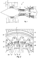
figure 2 montre en perspective le détail d'un rotor de soufflante de turboréacteur du côté de la bride amont du compresseur de gavage ; - La
figure 3 montre en perspective la bride amont du tambour du compresseur avec des zones de lamage. - La
figure 4 montre la bride de face et en coupe au travers du pion anti-usure montée dans un trou de décharge ; - La
figure 5 montre une variante de réalisation du montage des pions anti-usure avec et sans élément mâle de verrouillage.
- The
figure 1 represents, in axial section, a turbojet engine to which the invention applies; - The
figure 2 shows in perspective the detail of a turbojet fan rotor on the side of the upstream flange of the booster compressor; - The
figure 3 shows in perspective the upstream flange of the compressor drum with countersinks. - The
figure 4 shows the face flange and in section through the anti-wear pin mounted in a discharge hole; - The
figure 5 shows an alternative embodiment of the assembly of anti-wear pins with and without male locking element.
On a représenté sur la
En aval du compresseur de gavage 4, l'air est encore comprimé par le compresseur à haute pression 5. Ce dernier est solidaire en rotation de l'étage de turbine à haute pression 7 par lequel il est entraîné. L'air comprimé entre dans la chambre de combustion 6 qui produit les gaz chauds pour entraîner les étages de turbine.Downstream of the
L'invention concerne, dans cet exemple, la partie du moteur située entre le rotor 2 de soufflante et le rotor 4 du compresseur à basse pression.In this example, the invention relates to the portion of the motor situated between the
On a représenté sur la
Le disque 20 de soufflante comprend des alvéoles 21 sur sa jante. Ceux-ci sont orientés globalement axialement, c'est-à-dire dans l'axe du moteur, avec ici une forme curviligne. Les alvéoles sont à section transversale en queue d'aronde pour retenir les aubes radialement. La jante comprend des brides radiales transversales 22 entre les alvéoles pour la fixation de plateformes inter-aubes non représentées. Le disque 20 est solidaire du compresseur à basse pression 40 dit de gavage, situé en aval. Le compresseur 40 comprend un tambour 41 cylindrique sur lequel sont fixées les aubes de compresseur 42 que l'on voit en partie. À l'amont, le tambour est solidaire d'une bride transversale radiale 43, formant un anneau et sur laquelle la jante du disque 20 est boulonnée. La jante comprend des brides de fixation radiales 23 entre les alvéoles 21. Chaque bride radiale 23 est fixée par un boulon 24 à la bride amont 43 du compresseur. On note que les trous présents sur la bride amont 43 du tambour du compresseur n'ont pas tous la même fonction ; des trous de liaison 43F permettent d'assurer la liaison par boulonnage du disque au tambour et des trous de décharge 43D protègent les trous de liaison du flux de contraintes circonférentiel. Les boulons 24 sont logés dans les trous de liaison 43F. Les trous de liaison 43F ont un diamètre légèrement supérieur à celui des trous de décharge 43D. Trois trous de décharges sont ici prévus entre deux trous de liaison. Ils sont disposés sur une même couronne circulaire. Des bouchons d'étanchéité non représentés obturent les orifices 43D et évitent que l'air à l'aval, à l'intérieur de la cavité du tambour, ne fuie par les perçages vers l'amont dont la pression est inférieure. Ces bouchons d'étanchéité sont en matière synthétique et n'assurent aucune autre fonction.The
La bride amont 43 présente des encoches de rétention 43a avec des bords radiaux et qui sont ouvertes vers l'axe de la machine. Ces encoches servent à retenir axialement les aubes par introduction du crochet de ces dernières qui sont logées dans les alvéoles 21 situés en vis-à-vis. Ce mode de retenue des aubes est décrit dans le brevet au nom de la demanderesse
Lorsque le moteur est au sol, la mise en autorotation de la soufflante provoque un débattement tangentiel des aubes Fan. Dans un tel cas, les aubes viennent frotter contre la bride 43 par la face aval de leur échasse. La pression et les déplacements des aubes entraînent une usure à la fois de l'aube et de la bride amont. On a indiqué sur ce rotor la disposition des marques T d'usure laissées par les échasses des aubes sur la bride 43. Ces marquent reproduisent la forme de la section des échasses des aubes ; elle est de forme rectangulaire. Elles sont situées dans le prolongement des alvéoles dans lesquelles les aubes sont logées et chevauchent notamment des trous de décharge 43D.When the engine is on the ground, the autorotation of the fan causes a tangential deflection of the vanes Fan. In such a case, the blades come rub against the
On décrit maintenant le procédé de réparation de l'invention. On usine conformément à celle-ci un lamage optimisé 43L dans la zone de chaque marque d'usure T, voir
Afin de ne pas remettre en cause les conditions de serrage des brides 23 du disque 20 sur la bride 43 du tambour par les boulons 24, l'étendue circonférentielle des lamages est limitée. En particulier les zones de contact par lesquelles les brides 23 du disque 20 sont serrées sur la bride du tambour ne sont pas usinées.In order not to call into question the clamping conditions of the
Par ailleurs, l'optimisation du lamage vise à ne pas diminuer la durée de vie de la pièce. Dans ce but, on fait en sorte qu'au moins l'une des bordures 43L1 ou 43L2 passe entre deux trous de décharge 43D adjacents. De ce fait, on réduit globalement le risque d'apparition de criques à l'intersection des bordures avec les trous de décharge.Furthermore, the optimization of the counterbore is not to reduce the life of the part. For this purpose, it is arranged that at least one of the borders 43L1 or 43L2 passes between two adjacent 43D discharge holes. As a result, the risk of occurrence of cracks at the intersection of the curbs with the discharge holes is generally reduced.
Dans le but également de ne pas réduire la durée de vie de la pièce, on établit un compromis entre la profondeur du lamage nécessaire pour que le rayon de raccordement le long des bordures et la diminution de la section travaillante radiale et circonférentielle.In order also not to reduce the service life of the part, a compromise is made between the depth of the counterbore necessary for the connection radius along the edges and the reduction of the radial and circumferential working section.
L'optimisation du lamage prend encore en considération la tenue de la pièce aux sollicitations résultant de la perte d'une aube. En cas de perte d'une aube, les zones situées de part et d'autre des encoches assurent la rétention axiale des aubes et participe directement à la souplesse du système de rétention aval. L'étendue du lamage est donc limitée radialement de manière à minimiser son impact sur la souplesse axiale du système de rétention aval des aubes de soufflante. Les bords radiaux de l'encoche 43a ne sont ainsi pas usinés, leur épaisseur n'est pas modifiée.Optimizing the counterbore still takes into account the resistance of the part to the stresses resulting from the loss of a blade. In the event of a blade being lost, the zones located on either side of the notches ensure the axial retention of the blades and participate directly in the flexibility of the downstream retention system. The extent of the counterbore is thus limited radially so as to minimize its impact on the axial flexibility of the downstream retention system of the fan blades. The radial edges of the
Concernant le fond de l'encoche, afin d'éviter une diminution de la surface de contact entre le crochet de l'aube et le fond de l'encoche, la profondeur du lamage est limitée à celle du chanfrein existant à l'intersection entre le lamage et le fond 43af de l'encocheWith regard to the bottom of the notch, in order to avoid a reduction of the contact surface between the blade hook and the bottom of the notch, the depth of the counterbore is limited to that of the existing chamfer at the intersection between the countersink and the bottom 43af of the notch
Concernant la profondeur du lamage, il est suffisamment profond pour supprimer la totalité des marques d'usure constatées au niveau des talons des aubes.Regarding the depth of the countersink, it is deep enough to remove all wear marks found at the blade heels.
Concernant les pions anti-usure 50 rapportés dans le trou de décharge 43D en vis-à-vis des alvéoles du disque, on prend en compte les considérations suivantes :
- Maximiser l'épaisseur de la collerette pour garantir la tenue mécanique de la collerette lors du montage et en fonctionnement.
- Maximize the thickness of the flange to ensure the mechanical strength of the flange during assembly and operation.
Choix d'un matériau métallique qui permet de résister aux sollicitations de montage et qui présente un bon comportement à l'usure. Il est apparu qu'un alliage à base Ni, tel que l'Inconel 718 satisfaisait à cette contrainte.Choice of a metallic material which makes it possible to withstand mounting stresses and exhibits good wear behavior. It appeared that an Ni-based alloy such as Inconel 718 satisfied this constraint.
Montage glissant des pions 50 dans les orifices 43D de manière à ne pas risquer d'endommager ou rayer la bride en alliage de titane.Sliding mounting
Un montage glissant convenant à cette condition est le frettage. Il comprend un refroidissement du pion à l'azote liquide combiné à un chauffage de la pièce à température limitée de manière à ne pas relaxer les contraintes résiduelles de grenaillage dans les couches superficielles. Un frettage avantageux comprend le refroidissement du pion en Inconel 718 à l'azote liquide à -196°C combiné à un chauffage de la pièce en alliage de titane, tel que le TA6V, entre 250°C et 350°C pendant une heure.A slippery fitting for this condition is the hooping. It comprises cooling the pin with liquid nitrogen combined with heating the room at a limited temperature so as not to relax the residual stresses of shot blasting in the surface layers. Advantageous shrinking includes cooling the Inconel 718 pin to liquid nitrogen at -196 ° C combined with heating the titanium alloy part, such as TA6V, between 250 ° C and 350 ° C for one hour.
Des essais de faisabilité du montage ont été réalisés sur 160 trous. Aucun endommagement du tambour n'a été constaté lors du montage des pions anti-usure.Feasibility tests of the assembly were carried out on 160 holes. No damage to the drum was observed during the assembly of the anti-wear pins.
Des solutions alternatives au frettage du pion avec des risques faibles d'endommagement du tambour et sans mise en place dans l'orifice de décharge impliquant le chauffage de la pièce, sont envisageables.Alternative solutions to the hooping of the pin with low risk of damage to the drum and without implementation in the discharge port involving the heating of the room, are conceivable.
Dans la
Selon un autre mode de réalisation le fut du pion peut être fendu et avoir une forme légèrement évasée. Le pion est mis en place par rétreint des bords fendus du fut au moyen d'un outil adapté.According to another embodiment, the pin may be split and have a slightly flared shape. The pin is set up by necking the slotted edges of the was by means of a suitable tool.
Claims (10)
- A method for repairing a flange (43) of a rotor on the transverse face of which there is attached a disk (20) of a fan in an engine having an upstream turbofan, the flange comprising, in a ring shape, openings (43F) for connecting to the disk (20) and, between these, openings (43D) termed stress-relief openings, wear marks (T) being formed by the fan blades rubbing on the flange, the method comprising a step of machining spot faces (43L) on the flange in the regions having wear marks and a step of putting in place pegs (50, 150), known as anti-wear pegs, in the stress-relief openings (43D) which are likely to be covered by the blades during rubbing, characterized in that the spot faces (43L) extend between the connection openings (43F) and are limited in the circumferential direction by the clamping surfaces of the connection between the disk and the flange.
- The method as claimed in the preceding claim, each spot face between two connection openings being defined by two radially oriented borders (43L1, 43L2), at least one of the borders is outside the stress-relief holes.
- The method as claimed in the preceding claim, according to which the depth of the spot face (43L) is determined so as to obtain a sufficient spot facing base radius along said borders (43L1, 43L2) in order to avoid stress concentrations along said borders while limiting the reduction in the effective cross section of the flange in the spot facing region.
- The method as claimed in either of claims 2 and 3, the flange comprising radial scallops (43a) for receiving axial hooks of the blades, according to which the radial borders extend radially as far as the base of the scallops.
- The method as claimed in the preceding claim, the base of the scallops having a chamfer, according to which the depth of the spot face is limited such that it is less than that of the chamfer.
- The method as claimed in one of the preceding claims, according to which an anti-wear peg, having a stem and a collar, is arranged by sliding assembly in the stress-relief opening which may be covered by a fan blade, the peg being made of metal.
- The method as claimed in the preceding claim, according to which the sliding assembly is created by shrink-fitting the stem of the peg in the stress-relief opening.
- The method as claimed in the preceding claim, the flange surface having undergone shot peening, the heating of the flange is carried out for a predetermined period and up to a predetermined temperature such that it does not relieve the residual stresses from the shot peening.
- The method as claimed in claim 1, the stem of the peg (150) being deformable in the radial direction, a plug for radially stretching the stem is arranged on the side opposite the collar.
- The method as claimed in claim 1, the stem of the peg being deformable in the radial direction, the stem is pinched such that it can be inserted into the opening, after which the pinching is released.
Applications Claiming Priority (2)
| Application Number | Priority Date | Filing Date | Title |
|---|---|---|---|
| FR1250887A FR2986284B1 (en) | 2012-01-31 | 2012-01-31 | PROCESS FOR REPAIRING WEAR MARKS. |
| PCT/FR2013/050177 WO2013114032A1 (en) | 2012-01-31 | 2013-01-28 | Method for repairing wear marks on a rotor supporting the fan of a bypass engine |
Publications (2)
| Publication Number | Publication Date |
|---|---|
| EP2809954A1 EP2809954A1 (en) | 2014-12-10 |
| EP2809954B1 true EP2809954B1 (en) | 2016-04-06 |
Family
ID=47754773
Family Applications (1)
| Application Number | Title | Priority Date | Filing Date |
|---|---|---|---|
| EP13706582.7A Active EP2809954B1 (en) | 2012-01-31 | 2013-01-28 | Method of repair of wear zones on a rotor mounting the fan of a gas turbine engine |
Country Status (4)
| Country | Link |
|---|---|
| US (1) | US9512724B2 (en) |
| EP (1) | EP2809954B1 (en) |
| FR (1) | FR2986284B1 (en) |
| WO (1) | WO2013114032A1 (en) |
Families Citing this family (6)
| Publication number | Priority date | Publication date | Assignee | Title |
|---|---|---|---|---|
| US10370997B2 (en) * | 2015-05-26 | 2019-08-06 | Rolls-Royce Corporation | Turbine shroud having ceramic matrix composite seal segment |
| FR3055565B1 (en) * | 2016-09-02 | 2018-08-17 | Safran Aircraft Engines | SUSPENSION IN VIS-A-VIS FOR THE REPAIR OF TIGHTENING HOLES |
| US10357776B2 (en) * | 2016-09-09 | 2019-07-23 | Comcorp, Inc. | Impact cutter blade and holder system and method |
| US11015483B2 (en) | 2018-03-09 | 2021-05-25 | General Electric Company | High pressure compressor flow path flanges with leak resistant plates for improved compressor efficiency and cyclic life |
| US11421555B2 (en) * | 2018-12-07 | 2022-08-23 | Raytheon Technologies Corporation | Case flange with scallop features |
| IT202100029963A1 (en) * | 2021-11-26 | 2023-05-26 | Ge Avio Srl | GAS TURBINE ENGINE INCLUDING A ROTATING BLADE ASSEMBLY. |
Family Cites Families (8)
| Publication number | Priority date | Publication date | Assignee | Title |
|---|---|---|---|---|
| US1955728A (en) * | 1932-04-09 | 1934-04-24 | Colony Man Corp | Chilling method and tool for expansion fits |
| FR1060087A (en) | 1952-05-16 | 1954-03-30 | Ile D Etudes Pour La Fabricati | Improvements to eyeshadow distributors |
| FR2566061B1 (en) | 1984-06-14 | 1988-09-02 | Snecma | AXIAL LOCKING DEVICE OF A TURBOMACHINE BLADE |
| FR2844562B1 (en) * | 2002-09-18 | 2004-10-29 | Snecma Moteurs | CONTROL OF THE AXIAL POSITION OF A BLOWER ROTOR BLADE |
| FR2903154B1 (en) | 2006-06-29 | 2011-10-28 | Snecma | ROTOR OF TURBOMACHINE AND TURBOMACHINE COMPRISING SUCH A ROTOR |
| FR2929660B1 (en) | 2008-04-07 | 2012-11-16 | Snecma | ANTI-WEAR DEVICE FOR TURBOMACHINE ROTOR, CAP FORMING ANTI-WEAR DEVICE AND ROTOR COMPRESSOR OF GAS TURBINE ENGINE HAVING ANTI-WEAR CAP |
| FR2933887B1 (en) * | 2008-07-18 | 2010-09-17 | Snecma | PROCESS FOR REPAIRING OR RETRIEVING A TURBOMACHINE DISK AND TURBOMACHINE DISK REPAIRED OR RECOVERED |
| FR2948725B1 (en) * | 2009-07-28 | 2012-10-05 | Snecma | ANTI-WEAR DEVICE FOR A TURBOMACHINE ROTOR |
-
2012
- 2012-01-31 FR FR1250887A patent/FR2986284B1/en not_active Expired - Fee Related
-
2013
- 2013-01-28 EP EP13706582.7A patent/EP2809954B1/en active Active
- 2013-01-28 WO PCT/FR2013/050177 patent/WO2013114032A1/en active Application Filing
- 2013-01-28 US US14/374,282 patent/US9512724B2/en active Active
Also Published As
| Publication number | Publication date |
|---|---|
| CN104067000A (en) | 2014-09-24 |
| US9512724B2 (en) | 2016-12-06 |
| FR2986284B1 (en) | 2014-03-28 |
| FR2986284A1 (en) | 2013-08-02 |
| US20150040395A1 (en) | 2015-02-12 |
| WO2013114032A1 (en) | 2013-08-08 |
| EP2809954A1 (en) | 2014-12-10 |
Similar Documents
| Publication | Publication Date | Title |
|---|---|---|
| EP2809954B1 (en) | Method of repair of wear zones on a rotor mounting the fan of a gas turbine engine | |
| EP2276911B1 (en) | Turbomachine rotor comprising an anti-wear plug, and anti-wear plug | |
| EP2315642B1 (en) | Method of repairing or reworking a turbomachine disk | |
| EP1455055B1 (en) | Turbomachine with cooled shroud segments | |
| CA2607238C (en) | Turbomachinery rotor balancing system | |
| FR2968363A1 (en) | Rotor for use in turbojet engine e.g. turbofan engine, has annular wedge arranged and interposed between disk and ring and forming axial support surface against which paddles placed in slots are supported | |
| CA2475043C (en) | Rotor flange retainer | |
| CA2931044C (en) | Device for centering and guiding in rotation with a turbomachine shaft and comprising methods for retaining the bearing outer race | |
| FR2941487A1 (en) | TURBOMACHINE DRAFT IN COMPOSITE MATERIAL WITH A REINFORCED FOOT | |
| EP2459884A2 (en) | Outer shell sector for a bladed stator ring of an aircraft turbine engine, comprising vibration-damping blocks | |
| EP2706242A1 (en) | Fixing of blades on an axial compressor drum | |
| EP3033495B1 (en) | Improvement for the locking of blade-supporting components | |
| FR2948725A1 (en) | ANTI-WEAR DEVICE FOR A TURBOMACHINE ROTOR | |
| FR2992680A1 (en) | TURBOMACHINE TOURILLON COMPRISING A CROWN FOR RECOVERING A FLOW OF LUBRICATING OIL WITH A PLURALITY OF ORIFICES | |
| EP2795068A1 (en) | Turbomachine compressor guide vanes assembly | |
| FR2993599A1 (en) | TURBOMACHINE LABYRINTH DISK | |
| WO2013083905A1 (en) | Unlockable device for axially arresting a sealing ring with which an aircraft turbomachine module rotor wheel makes contact | |
| FR2968349A1 (en) | SINGLET® STEAM TURBINE INTERFACE FOR MARGINAL STORAGE DISTRIBUTORS WITH INTERNAL RING | |
| FR2948737A1 (en) | Outer shell sector forming assembly for bladed ring sector of turbine or compressor stator in turbojet engine of aircraft, has vibration-damping block supported against two friction surfaces respectively provided on two elementary sectors | |
| FR3040191A1 (en) | AIRCRAFT TURBOMACHINE PROPELLER COMPRISING IMPROVED RADIAL RETENTION MEANS FOR PROPELLER BLADE | |
| FR3028781A1 (en) | AIRCRAFT TURBOMACHINE ROTOR PIECE COMPRISING A MACHINEABLE ANNULAR PROTUBERANCE PROVIDED WITH A DEHYLING ORIFICE AND METHOD OF PREPARING THE SAME | |
| WO2019141918A1 (en) | Turbomachine ring | |
| FR3099888A1 (en) | Tools for extracting a turbomachine retaining ring | |
| FR3083820A1 (en) | IMPROVED HOLDING DEVICE FOR A TURBOMACHINE DISPENSER | |
| FR3039201A1 (en) | THERMAL PROTECTION TURBOMACHINE PART HAVING PINS |
Legal Events
| Date | Code | Title | Description |
|---|---|---|---|
| PUAI | Public reference made under article 153(3) epc to a published international application that has entered the european phase |
Free format text: ORIGINAL CODE: 0009012 |
|
| 17P | Request for examination filed |
Effective date: 20140821 |
|
| AK | Designated contracting states |
Kind code of ref document: A1 Designated state(s): AL AT BE BG CH CY CZ DE DK EE ES FI FR GB GR HR HU IE IS IT LI LT LU LV MC MK MT NL NO PL PT RO RS SE SI SK SM TR |
|
| AX | Request for extension of the european patent |
Extension state: BA ME |
|
| DAX | Request for extension of the european patent (deleted) | ||
| GRAP | Despatch of communication of intention to grant a patent |
Free format text: ORIGINAL CODE: EPIDOSNIGR1 |
|
| INTG | Intention to grant announced |
Effective date: 20150929 |
|
| RAP1 | Party data changed (applicant data changed or rights of an application transferred) |
Owner name: SNECMA |
|
| GRAS | Grant fee paid |
Free format text: ORIGINAL CODE: EPIDOSNIGR3 |
|
| GRAA | (expected) grant |
Free format text: ORIGINAL CODE: 0009210 |
|
| AK | Designated contracting states |
Kind code of ref document: B1 Designated state(s): AL AT BE BG CH CY CZ DE DK EE ES FI FR GB GR HR HU IE IS IT LI LT LU LV MC MK MT NL NO PL PT RO RS SE SI SK SM TR |
|
| REG | Reference to a national code |
Ref country code: GB Ref legal event code: FG4D Free format text: NOT ENGLISH |
|
| REG | Reference to a national code |
Ref country code: AT Ref legal event code: REF Ref document number: 788147 Country of ref document: AT Kind code of ref document: T Effective date: 20160415 Ref country code: CH Ref legal event code: EP |
|
| REG | Reference to a national code |
Ref country code: IE Ref legal event code: FG4D Free format text: LANGUAGE OF EP DOCUMENT: FRENCH |
|
| REG | Reference to a national code |
Ref country code: DE Ref legal event code: R096 Ref document number: 602013006247 Country of ref document: DE |
|
| REG | Reference to a national code |
Ref country code: SE Ref legal event code: TRGR |
|
| REG | Reference to a national code |
Ref country code: LT Ref legal event code: MG4D Ref country code: NL Ref legal event code: MP Effective date: 20160406 |
|
| REG | Reference to a national code |
Ref country code: AT Ref legal event code: MK05 Ref document number: 788147 Country of ref document: AT Kind code of ref document: T Effective date: 20160406 |
|
| RAP2 | Party data changed (patent owner data changed or rights of a patent transferred) |
Owner name: SAFRAN AIRCRAFT ENGINES |
|
| PG25 | Lapsed in a contracting state [announced via postgrant information from national office to epo] |
Ref country code: NL Free format text: LAPSE BECAUSE OF FAILURE TO SUBMIT A TRANSLATION OF THE DESCRIPTION OR TO PAY THE FEE WITHIN THE PRESCRIBED TIME-LIMIT Effective date: 20160406 |
|
| PG25 | Lapsed in a contracting state [announced via postgrant information from national office to epo] |
Ref country code: FI Free format text: LAPSE BECAUSE OF FAILURE TO SUBMIT A TRANSLATION OF THE DESCRIPTION OR TO PAY THE FEE WITHIN THE PRESCRIBED TIME-LIMIT Effective date: 20160406 Ref country code: IS Free format text: LAPSE BECAUSE OF FAILURE TO SUBMIT A TRANSLATION OF THE DESCRIPTION OR TO PAY THE FEE WITHIN THE PRESCRIBED TIME-LIMIT Effective date: 20160806 Ref country code: LT Free format text: LAPSE BECAUSE OF FAILURE TO SUBMIT A TRANSLATION OF THE DESCRIPTION OR TO PAY THE FEE WITHIN THE PRESCRIBED TIME-LIMIT Effective date: 20160406 Ref country code: PL Free format text: LAPSE BECAUSE OF FAILURE TO SUBMIT A TRANSLATION OF THE DESCRIPTION OR TO PAY THE FEE WITHIN THE PRESCRIBED TIME-LIMIT Effective date: 20160406 Ref country code: NO Free format text: LAPSE BECAUSE OF FAILURE TO SUBMIT A TRANSLATION OF THE DESCRIPTION OR TO PAY THE FEE WITHIN THE PRESCRIBED TIME-LIMIT Effective date: 20160706 |
|
| PG25 | Lapsed in a contracting state [announced via postgrant information from national office to epo] |
Ref country code: ES Free format text: LAPSE BECAUSE OF FAILURE TO SUBMIT A TRANSLATION OF THE DESCRIPTION OR TO PAY THE FEE WITHIN THE PRESCRIBED TIME-LIMIT Effective date: 20160406 Ref country code: LV Free format text: LAPSE BECAUSE OF FAILURE TO SUBMIT A TRANSLATION OF THE DESCRIPTION OR TO PAY THE FEE WITHIN THE PRESCRIBED TIME-LIMIT Effective date: 20160406 Ref country code: AT Free format text: LAPSE BECAUSE OF FAILURE TO SUBMIT A TRANSLATION OF THE DESCRIPTION OR TO PAY THE FEE WITHIN THE PRESCRIBED TIME-LIMIT Effective date: 20160406 Ref country code: RS Free format text: LAPSE BECAUSE OF FAILURE TO SUBMIT A TRANSLATION OF THE DESCRIPTION OR TO PAY THE FEE WITHIN THE PRESCRIBED TIME-LIMIT Effective date: 20160406 Ref country code: GR Free format text: LAPSE BECAUSE OF FAILURE TO SUBMIT A TRANSLATION OF THE DESCRIPTION OR TO PAY THE FEE WITHIN THE PRESCRIBED TIME-LIMIT Effective date: 20160707 Ref country code: HR Free format text: LAPSE BECAUSE OF FAILURE TO SUBMIT A TRANSLATION OF THE DESCRIPTION OR TO PAY THE FEE WITHIN THE PRESCRIBED TIME-LIMIT Effective date: 20160406 Ref country code: PT Free format text: LAPSE BECAUSE OF FAILURE TO SUBMIT A TRANSLATION OF THE DESCRIPTION OR TO PAY THE FEE WITHIN THE PRESCRIBED TIME-LIMIT Effective date: 20160808 |
|
| REG | Reference to a national code |
Ref country code: FR Ref legal event code: PLFP Year of fee payment: 5 |
|
| REG | Reference to a national code |
Ref country code: DE Ref legal event code: R097 Ref document number: 602013006247 Country of ref document: DE |
|
| PG25 | Lapsed in a contracting state [announced via postgrant information from national office to epo] |
Ref country code: RO Free format text: LAPSE BECAUSE OF FAILURE TO SUBMIT A TRANSLATION OF THE DESCRIPTION OR TO PAY THE FEE WITHIN THE PRESCRIBED TIME-LIMIT Effective date: 20160406 Ref country code: EE Free format text: LAPSE BECAUSE OF FAILURE TO SUBMIT A TRANSLATION OF THE DESCRIPTION OR TO PAY THE FEE WITHIN THE PRESCRIBED TIME-LIMIT Effective date: 20160406 Ref country code: CZ Free format text: LAPSE BECAUSE OF FAILURE TO SUBMIT A TRANSLATION OF THE DESCRIPTION OR TO PAY THE FEE WITHIN THE PRESCRIBED TIME-LIMIT Effective date: 20160406 Ref country code: SK Free format text: LAPSE BECAUSE OF FAILURE TO SUBMIT A TRANSLATION OF THE DESCRIPTION OR TO PAY THE FEE WITHIN THE PRESCRIBED TIME-LIMIT Effective date: 20160406 Ref country code: DK Free format text: LAPSE BECAUSE OF FAILURE TO SUBMIT A TRANSLATION OF THE DESCRIPTION OR TO PAY THE FEE WITHIN THE PRESCRIBED TIME-LIMIT Effective date: 20160406 |
|
| PLBE | No opposition filed within time limit |
Free format text: ORIGINAL CODE: 0009261 |
|
| STAA | Information on the status of an ep patent application or granted ep patent |
Free format text: STATUS: NO OPPOSITION FILED WITHIN TIME LIMIT |
|
| PG25 | Lapsed in a contracting state [announced via postgrant information from national office to epo] |
Ref country code: SM Free format text: LAPSE BECAUSE OF FAILURE TO SUBMIT A TRANSLATION OF THE DESCRIPTION OR TO PAY THE FEE WITHIN THE PRESCRIBED TIME-LIMIT Effective date: 20160406 |
|
| 26N | No opposition filed |
Effective date: 20170110 |
|
| PG25 | Lapsed in a contracting state [announced via postgrant information from national office to epo] |
Ref country code: BE Free format text: LAPSE BECAUSE OF NON-PAYMENT OF DUE FEES Effective date: 20170131 Ref country code: SI Free format text: LAPSE BECAUSE OF FAILURE TO SUBMIT A TRANSLATION OF THE DESCRIPTION OR TO PAY THE FEE WITHIN THE PRESCRIBED TIME-LIMIT Effective date: 20160406 |
|
| REG | Reference to a national code |
Ref country code: CH Ref legal event code: PL |
|
| PG25 | Lapsed in a contracting state [announced via postgrant information from national office to epo] |
Ref country code: MC Free format text: LAPSE BECAUSE OF FAILURE TO SUBMIT A TRANSLATION OF THE DESCRIPTION OR TO PAY THE FEE WITHIN THE PRESCRIBED TIME-LIMIT Effective date: 20160406 |
|
| PG25 | Lapsed in a contracting state [announced via postgrant information from national office to epo] |
Ref country code: CH Free format text: LAPSE BECAUSE OF NON-PAYMENT OF DUE FEES Effective date: 20170131 Ref country code: LI Free format text: LAPSE BECAUSE OF NON-PAYMENT OF DUE FEES Effective date: 20170131 |
|
| REG | Reference to a national code |
Ref country code: IE Ref legal event code: MM4A |
|
| PG25 | Lapsed in a contracting state [announced via postgrant information from national office to epo] |
Ref country code: LU Free format text: LAPSE BECAUSE OF NON-PAYMENT OF DUE FEES Effective date: 20170128 |
|
| REG | Reference to a national code |
Ref country code: FR Ref legal event code: PLFP Year of fee payment: 6 |
|
| REG | Reference to a national code |
Ref country code: BE Ref legal event code: MM Effective date: 20170131 |
|
| PG25 | Lapsed in a contracting state [announced via postgrant information from national office to epo] |
Ref country code: IE Free format text: LAPSE BECAUSE OF NON-PAYMENT OF DUE FEES Effective date: 20170128 |
|
| PG25 | Lapsed in a contracting state [announced via postgrant information from national office to epo] |
Ref country code: MT Free format text: LAPSE BECAUSE OF FAILURE TO SUBMIT A TRANSLATION OF THE DESCRIPTION OR TO PAY THE FEE WITHIN THE PRESCRIBED TIME-LIMIT Effective date: 20160406 |
|
| PG25 | Lapsed in a contracting state [announced via postgrant information from national office to epo] |
Ref country code: AL Free format text: LAPSE BECAUSE OF FAILURE TO SUBMIT A TRANSLATION OF THE DESCRIPTION OR TO PAY THE FEE WITHIN THE PRESCRIBED TIME-LIMIT Effective date: 20160406 |
|
| PG25 | Lapsed in a contracting state [announced via postgrant information from national office to epo] |
Ref country code: HU Free format text: LAPSE BECAUSE OF FAILURE TO SUBMIT A TRANSLATION OF THE DESCRIPTION OR TO PAY THE FEE WITHIN THE PRESCRIBED TIME-LIMIT; INVALID AB INITIO Effective date: 20130128 |
|
| PG25 | Lapsed in a contracting state [announced via postgrant information from national office to epo] |
Ref country code: BG Free format text: LAPSE BECAUSE OF FAILURE TO SUBMIT A TRANSLATION OF THE DESCRIPTION OR TO PAY THE FEE WITHIN THE PRESCRIBED TIME-LIMIT Effective date: 20160406 |
|
| PG25 | Lapsed in a contracting state [announced via postgrant information from national office to epo] |
Ref country code: CY Free format text: LAPSE BECAUSE OF FAILURE TO SUBMIT A TRANSLATION OF THE DESCRIPTION OR TO PAY THE FEE WITHIN THE PRESCRIBED TIME-LIMIT Effective date: 20160406 |
|
| PG25 | Lapsed in a contracting state [announced via postgrant information from national office to epo] |
Ref country code: MK Free format text: LAPSE BECAUSE OF FAILURE TO SUBMIT A TRANSLATION OF THE DESCRIPTION OR TO PAY THE FEE WITHIN THE PRESCRIBED TIME-LIMIT Effective date: 20160406 |
|
| PG25 | Lapsed in a contracting state [announced via postgrant information from national office to epo] |
Ref country code: TR Free format text: LAPSE BECAUSE OF FAILURE TO SUBMIT A TRANSLATION OF THE DESCRIPTION OR TO PAY THE FEE WITHIN THE PRESCRIBED TIME-LIMIT Effective date: 20160406 |
|
| PGFP | Annual fee paid to national office [announced via postgrant information from national office to epo] |
Ref country code: IT Payment date: 20230103 Year of fee payment: 11 Ref country code: DE Payment date: 20221220 Year of fee payment: 11 |
|
| PGFP | Annual fee paid to national office [announced via postgrant information from national office to epo] |
Ref country code: GB Payment date: 20231219 Year of fee payment: 12 |
|
| PGFP | Annual fee paid to national office [announced via postgrant information from national office to epo] |
Ref country code: SE Payment date: 20231219 Year of fee payment: 12 Ref country code: FR Payment date: 20231219 Year of fee payment: 12 |