EP2809904B1 - Procede d'ejection de gaz d'echappement de turbine a gaz et ensemble d'echappement de configuration optimisee - Google Patents
Procede d'ejection de gaz d'echappement de turbine a gaz et ensemble d'echappement de configuration optimisee Download PDFInfo
- Publication number
- EP2809904B1 EP2809904B1 EP13706619.7A EP13706619A EP2809904B1 EP 2809904 B1 EP2809904 B1 EP 2809904B1 EP 13706619 A EP13706619 A EP 13706619A EP 2809904 B1 EP2809904 B1 EP 2809904B1
- Authority
- EP
- European Patent Office
- Prior art keywords
- ejector
- pipe
- peripheral opening
- gas
- gas turbine
- Prior art date
- Legal status (The legal status is an assumption and is not a legal conclusion. Google has not performed a legal analysis and makes no representation as to the accuracy of the status listed.)
- Active
Links
Images

Classifications
-
- F—MECHANICAL ENGINEERING; LIGHTING; HEATING; WEAPONS; BLASTING
- F01—MACHINES OR ENGINES IN GENERAL; ENGINE PLANTS IN GENERAL; STEAM ENGINES
- F01D—NON-POSITIVE DISPLACEMENT MACHINES OR ENGINES, e.g. STEAM TURBINES
- F01D25/00—Component parts, details, or accessories, not provided for in, or of interest apart from, other groups
- F01D25/30—Exhaust heads, chambers, or the like
- F01D25/305—Exhaust heads, chambers, or the like with fluid, e.g. liquid injection
-
- B—PERFORMING OPERATIONS; TRANSPORTING
- B01—PHYSICAL OR CHEMICAL PROCESSES OR APPARATUS IN GENERAL
- B01F—MIXING, e.g. DISSOLVING, EMULSIFYING OR DISPERSING
- B01F25/00—Flow mixers; Mixers for falling materials, e.g. solid particles
- B01F25/30—Injector mixers
- B01F25/31—Injector mixers in conduits or tubes through which the main component flows
- B01F25/314—Injector mixers in conduits or tubes through which the main component flows wherein additional components are introduced at the circumference of the conduit
- B01F25/3143—Injector mixers in conduits or tubes through which the main component flows wherein additional components are introduced at the circumference of the conduit characterised by the specific design of the injector
- B01F25/31432—Injector mixers in conduits or tubes through which the main component flows wherein additional components are introduced at the circumference of the conduit characterised by the specific design of the injector being a slit extending in the circumferential direction only
-
- B—PERFORMING OPERATIONS; TRANSPORTING
- B64—AIRCRAFT; AVIATION; COSMONAUTICS
- B64D—EQUIPMENT FOR FITTING IN OR TO AIRCRAFT; FLIGHT SUITS; PARACHUTES; ARRANGEMENT OR MOUNTING OF POWER PLANTS OR PROPULSION TRANSMISSIONS IN AIRCRAFT
- B64D33/00—Arrangement in aircraft of power plant parts or auxiliaries not otherwise provided for
- B64D33/04—Arrangement in aircraft of power plant parts or auxiliaries not otherwise provided for of exhaust outlets or jet pipes
-
- F—MECHANICAL ENGINEERING; LIGHTING; HEATING; WEAPONS; BLASTING
- F01—MACHINES OR ENGINES IN GENERAL; ENGINE PLANTS IN GENERAL; STEAM ENGINES
- F01D—NON-POSITIVE DISPLACEMENT MACHINES OR ENGINES, e.g. STEAM TURBINES
- F01D25/00—Component parts, details, or accessories, not provided for in, or of interest apart from, other groups
- F01D25/30—Exhaust heads, chambers, or the like
-
- F—MECHANICAL ENGINEERING; LIGHTING; HEATING; WEAPONS; BLASTING
- F02—COMBUSTION ENGINES; HOT-GAS OR COMBUSTION-PRODUCT ENGINE PLANTS
- F02C—GAS-TURBINE PLANTS; AIR INTAKES FOR JET-PROPULSION PLANTS; CONTROLLING FUEL SUPPLY IN AIR-BREATHING JET-PROPULSION PLANTS
- F02C3/00—Gas-turbine plants characterised by the use of combustion products as the working fluid
- F02C3/32—Inducing air flow by fluid jet, e.g. ejector action
-
- F—MECHANICAL ENGINEERING; LIGHTING; HEATING; WEAPONS; BLASTING
- F05—INDEXING SCHEMES RELATING TO ENGINES OR PUMPS IN VARIOUS SUBCLASSES OF CLASSES F01-F04
- F05B—INDEXING SCHEME RELATING TO WIND, SPRING, WEIGHT, INERTIA OR LIKE MOTORS, TO MACHINES OR ENGINES FOR LIQUIDS COVERED BY SUBCLASSES F03B, F03D AND F03G
- F05B2260/00—Function
- F05B2260/60—Fluid transfer
- F05B2260/601—Fluid transfer using an ejector or a jet pump
-
- Y—GENERAL TAGGING OF NEW TECHNOLOGICAL DEVELOPMENTS; GENERAL TAGGING OF CROSS-SECTIONAL TECHNOLOGIES SPANNING OVER SEVERAL SECTIONS OF THE IPC; TECHNICAL SUBJECTS COVERED BY FORMER USPC CROSS-REFERENCE ART COLLECTIONS [XRACs] AND DIGESTS
- Y02—TECHNOLOGIES OR APPLICATIONS FOR MITIGATION OR ADAPTATION AGAINST CLIMATE CHANGE
- Y02T—CLIMATE CHANGE MITIGATION TECHNOLOGIES RELATED TO TRANSPORTATION
- Y02T50/00—Aeronautics or air transport
- Y02T50/60—Efficient propulsion technologies, e.g. for aircraft
Definitions
- the invention relates to a gas turbine exhaust gas ejection process and to an exhaust assembly having a junction between a nozzle and a configuration ejector adapted to implement this method.
- the field of the invention relates to gas turbines and more particularly to means dedicated to the exhaust of gases emitted by these turbines as described in EP 1780124 A .
- Helicopter engines typically include a gas generator (compressor assembly, combustion chamber, and turbine) that provides a high kinetic energy gas stream from a mixture of fuel and pressurized air injected into the chamber. of combustion, and a turbine driven in rotation by the gas flow to deliver mechanical power to an output shaft via a gear train.
- gas generator compressor assembly, combustion chamber, and turbine
- turbine turbine driven in rotation by the gas flow to deliver mechanical power to an output shaft via a gear train.
- This so-called power turbine is coupled to an exhaust nozzle, itself extended by an ejector, the assembly being intended to maintain the static pressure at the outlet of the free turbine at a low level and to limit the total pressure losses. .
- the efficiency of the free turbine and exhaust assembly is thus improved and the mechanical power transmitted to the output shaft is increased.
- the ejector may be advantageously bent to deflect the gas flow output of the beam or the tail rotor of the helicopter.
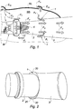
- the sectional drawing of the figure 1 illustrates the use of secondary fresh air streams Fs, originating from outside at ambient pressure via inlet passages E1a, E1b of the engine hood Mc and circulating in the engine bay Mb.
- the secondary flows Fs flow along the motor M as well as along the primary nozzle 2.
- these flows Fs are at least partially sucked through a peripheral opening 1 between the downstream end of the nozzle 2 and the upstream end of the ejector 3 which surrounds it at a distance.
- the secondary flows Fs are generated by the driving effect of the hot primary flux Fp exiting the nozzle 2, around the cone 4 as well as by the vacuum effect generated by the shape of the ejector 3.
- the shape of the The upstream end of the ejector 3 promotes the stability of the suction of the secondary flows generated by these two effects.
- the shape of the upstream end of the ejector 3 trunk is an example.
- the nominal operation of an ejector is to allow fresh air to be drawn through the opening 1 formed between this ejector 3 and the nozzle 2.
- the same opening 1 can be crossed - in the opposite direction - by hot primary air Fp which is then partially displaced, according to the arrows Fr, to the motor bay Mb.
- the motor bay Mb and the equipment are heated instead of being cooled.
- the secondary fresh air flow sucked is then decreased and the cooling of the hot gases of the primary flow at the outlet of the exhaust is accordingly attenuated.
- the invention aims to prevent the discharge of hot primary air via the peripheral opening described above. To do this, the invention provides for partially closing the peripheral opening to prevent the discharge of the primary flow in the engine bay.
- the subject of the present invention is a method for ejecting exhaust gas from a gas turbine using an exhaust nozzle of a primary flow of hot gases, the gas turbine comprising a motor equipment engine bay and provided with fresh air secondary flow inlets to ventilate the engine bay, cooling the engine equipment and the primary gas flow by mixing in the exhaust.
- the nozzle is extended by an ejector which surrounds it with a determined recovery rate to form together a gas exhaust vein.
- a peripheral opening is formed between the nozzle and the ejector.
- the position and the angle at the center of at least one sector of the peripheral opening likely to constitute a re-ingestion zone of the primary flow in the motor bay are determined by correlation of the interactions between the secondary flows and the primary flow at from the parameters of gyration and air velocity at the nozzle inlet, geometries of the vein and the engine bay, as well as the geometry and the position of the inputs of the secondary flows of cooling of the primary flow.
- This peripheral opening is then closed on the angular sector (s) thus identified and extends over at least substantially 30 degrees.
- the invention also relates to a gas turbine exhaust assembly adapted to implement the above method, and comprising a motor bay and an exhaust nozzle of a primary flow of hot gases.
- the nozzle is extended by an ejector which covers it over a given longitudinal distance, forming a peripheral opening between the nozzle and the ejector.
- Inlets of secondary flow of fresh air are formed in a bonnet which surrounds the engine bay.
- the peripheral opening has at least one closure which extends over an angular sector at least equal to substantially 30 degrees.
- the term “longitudinal” means along the center line of the gas turbine, the term “transverse” being defined perpendicular to that axis and the term “radial” extending in a transverse plane from this axis.
- the terms “upstream” and “downstream” refer to the overall direction of flow of airflows along the longitudinal axis of a gas turbine until they are finally ejected into the nozzle. In the illustrated examples, helicopters are propelled by gas turbines. Moreover, identical reference signs refer to the passages in which these elements are described.
- FIG. 1 With reference to the side view of the peripheral opening 1 of the figure 2 , an example of local closure of this opening 1 between a nozzle 2 and a bent ejector 3 of a gas turbine is illustrated.
- This closure is performed by a piece 20 attached to the nozzle 2 and the ejector 3 at the upstream end 30 of the ejector forming the raised edge "in a trunk" of this end.
- the part may be sheet metal or composite material. Any suitable means of joining can be used: welding, gluing, etc.
- the closing piece 20 extends over an angular sector substantially equal to 120 °.
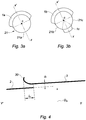
- the closed section 21 may extend, respectively, according to a single sector 21a of the order of 180 ° ( figure 3a ) or in two sectors 21b and 21c of angle at the center C equal to 60 ° each ( figure 3b ).
- the closed sectors 21a, and 21b-21c are supplemented by open sectors 1a, and 1b-1c.
- the closed sectors 21b and 21c are of the same extension, separated by an intermediate open sector 1c of angle at the center C equal to about 60 °, the latter being generally diametrically opposed to the remainder of the peripheral opening 1b of greater amplitude than the intermediate sector 1c, angle in the center of the order of 180 °. More specifically, the open sectors 1a, 1b and 1c extend symmetrically about the radial axis x'x oriented according to the position of the inlet of the secondary fresh air flow, as described below.
- the position and the angle at the center of the sectors of the peripheral opening are determined by correlating the interactions by modeling, for example using digital tools, between the secondary flows Fs and the primary flow Fp from the parameters of gyration and air speed at the free turbine inlet 12 ( figure 1 ), geometries of the exhaust vein and the motor bay Mb, as well as the geometry and the position of the inputs of the secondary flows E1a and E1b.
- This peripheral opening is then closed on the angular sectors thus identified.
- FIG. 21 An example of positioning of a closed section 21 of the peripheral opening 1 is presented with reference to the view in partial longitudinal section of the figure 5 , referring to the rear end of a gas turbine.
- the closed section 21 extends according to a suitable curvature "in continuity" from the upstream end 3a of the ejector 3 which then couples with the nozzle 2.
- the last air intake passage E1 b of a secondary flow Fs is disposed at the same radial level as the suction of these secondary flow Fs in the opening 1 between the nozzle 2 and the ejector 3.
- the section 21 is then positioned radially opposite to the passage of the air intake E1 b of the secondary flow Fs through the engine bonnet Mc of the engine bay Mb.
- the "continuous" type junction or equivalent has the advantage of being able to eliminate the fastening tabs between the nozzle and the ejector, in particular when the closed sectors extend over more than 180 °.
- the rear end of a gas turbine comprises an elbow ejector 3.
- the closed section 21 extends over an angular sector positioned on an upstream portion of the external curvature Ce formed by the elbow 33 of the ejector.
- the invention is not limited to the embodiments described and shown.
- other configurations may be provided to guide the secondary flows in the engine bay to cool the primary flow.
- the gyration of the air at the outlet of the free turbine is an essential parameter for determining the air gyration at the nozzle inlet.
- the geometry of the exhaust gas depends in particular on a configuration at least partially axisymmetric nozzle vein, the presence and the number of arms or obstacles in the exhaust vein.
- the nozzle and ejector may have several elbows: the number and position of the elbows may also be factors to consider.
Landscapes
- Engineering & Computer Science (AREA)
- Mechanical Engineering (AREA)
- Chemical & Material Sciences (AREA)
- General Engineering & Computer Science (AREA)
- Combustion & Propulsion (AREA)
- Aviation & Aerospace Engineering (AREA)
- Chemical Kinetics & Catalysis (AREA)
- Jet Pumps And Other Pumps (AREA)
- Supercharger (AREA)
- Exhaust Silencers (AREA)
Priority Applications (1)
| Application Number | Priority Date | Filing Date | Title |
|---|---|---|---|
| PL13706619T PL2809904T3 (pl) | 2012-02-01 | 2013-02-01 | Sposób wyrzucania gazów spalinowych z turbiny gazowej oraz zespół wydechowy o zoptymalizowanej konfiguracji |
Applications Claiming Priority (2)
| Application Number | Priority Date | Filing Date | Title |
|---|---|---|---|
| FR1250934A FR2986275B1 (fr) | 2012-02-01 | 2012-02-01 | Procede d'ejection de gaz d'echappement de turbine a gaz et ensemble d'echappement de configuration optimisee |
| PCT/FR2013/050222 WO2013114058A1 (fr) | 2012-02-01 | 2013-02-01 | Procede d'ejection de gaz d'echappement de turbine a gaz et ensemble d'echappement de configuration optimisee |
Publications (2)
| Publication Number | Publication Date |
|---|---|
| EP2809904A1 EP2809904A1 (fr) | 2014-12-10 |
| EP2809904B1 true EP2809904B1 (fr) | 2017-11-08 |
Family
ID=47754808
Family Applications (1)
| Application Number | Title | Priority Date | Filing Date |
|---|---|---|---|
| EP13706619.7A Active EP2809904B1 (fr) | 2012-02-01 | 2013-02-01 | Procede d'ejection de gaz d'echappement de turbine a gaz et ensemble d'echappement de configuration optimisee |
Country Status (11)
| Country | Link |
|---|---|
| US (1) | US9926809B2 (pl) |
| EP (1) | EP2809904B1 (pl) |
| JP (1) | JP6423718B2 (pl) |
| KR (1) | KR102015154B1 (pl) |
| CN (1) | CN104040147B (pl) |
| CA (1) | CA2860080C (pl) |
| ES (1) | ES2649019T3 (pl) |
| FR (1) | FR2986275B1 (pl) |
| PL (1) | PL2809904T3 (pl) |
| RU (1) | RU2635001C2 (pl) |
| WO (1) | WO2013114058A1 (pl) |
Families Citing this family (13)
| Publication number | Priority date | Publication date | Assignee | Title |
|---|---|---|---|---|
| FR3028888B1 (fr) * | 2014-11-25 | 2016-12-09 | Snecma | Dispositif de refroidissement pour une turbomachine alimente par un circuit de decharge |
| CA2996285C (en) | 2015-09-02 | 2023-10-31 | Jetoptera, Inc. | Ejector and airfoil configurations |
| US11965456B2 (en) * | 2015-09-02 | 2024-04-23 | Jetoptera, Inc. | Fluidic turbo heater system |
| USD868627S1 (en) | 2018-04-27 | 2019-12-03 | Jetoptera, Inc. | Flying car |
| US20170283080A1 (en) * | 2015-09-02 | 2017-10-05 | Jetoptera, Inc. | Winglet ejector configurations |
| US10464668B2 (en) | 2015-09-02 | 2019-11-05 | Jetoptera, Inc. | Configuration for vertical take-off and landing system for aerial vehicles |
| CN106988850A (zh) * | 2017-03-15 | 2017-07-28 | 中国航空工业集团公司西安飞机设计研究所 | 一种飞机发动机排气管及具有其的飞机 |
| CN108614920B (zh) * | 2018-04-03 | 2021-10-12 | 同济大学 | 一种多台设备局部排风同时系数确定方法 |
| RU2696521C1 (ru) * | 2018-05-17 | 2019-08-02 | Общество с ограниченной ответственностью "Газпром трансгаз Ухта" | Способ снижения температуры воздуха в полости между коническим корпусом силовой турбины двигателя ал-31стн и внутренним корпусом улитки газоперекачивающего агрегата ц1-16л/76-1,44 |
| US11105511B2 (en) * | 2018-12-14 | 2021-08-31 | General Electric Company | Rotating detonation propulsion system |
| KR20200113593A (ko) * | 2019-03-26 | 2020-10-07 | 이태준 | 배관 직결형 터보압축기 |
| US11772783B2 (en) * | 2020-05-19 | 2023-10-03 | Lockheed Martin Corporation | Turbine engine secondary ejector system |
| FR3143008B1 (fr) * | 2022-12-09 | 2024-11-01 | Airbus Helicopters | Aéronef muni d’un moteur et d’un conduit d’échappement autour d’une tuyère d’éjection du moteur |
Family Cites Families (17)
| Publication number | Priority date | Publication date | Assignee | Title |
|---|---|---|---|---|
| US4018046A (en) * | 1975-07-17 | 1977-04-19 | Avco Corporation | Infrared radiation suppressor for gas turbine engine |
| US4178760A (en) * | 1976-12-02 | 1979-12-18 | Filterwerk Mann & Hummel Gmbh | Filter dust ejector and check valve arrangement in exhaust system of internal combustion engine |
| SU1804042A1 (ru) * | 1991-03-28 | 1994-01-15 | Киевский механический завод им.О.К.Антонова | Система охлаждения теплообменника двигателя |
| US5265408A (en) * | 1992-02-13 | 1993-11-30 | Allied-Signal Inc. | Exhaust eductor cooling system |
| US5628623A (en) * | 1993-02-12 | 1997-05-13 | Skaggs; Bill D. | Fluid jet ejector and ejection method |
| US5655359A (en) * | 1995-05-15 | 1997-08-12 | The Boeing Company | Passive cooling device and method for cooling an auxiliary power unit on an airplane |
| DE19619535C1 (de) * | 1996-05-15 | 1997-10-30 | Daimler Benz Aerospace Airbus | Ejektor-Ölkühlsystem für ein Flugzeug-Hilfstriebwerk |
| US6092360A (en) * | 1998-07-01 | 2000-07-25 | The Boeing Company | Auxiliary power unit passive cooling system |
| US6202413B1 (en) * | 1999-02-04 | 2001-03-20 | Cummins Engine Company, Inc. | Multiple nozzle ejector for wastegated turbomachinery |
| US6651929B2 (en) * | 2001-10-29 | 2003-11-25 | Pratt & Whitney Canada Corp. | Passive cooling system for auxiliary power unit installation |
| US7152410B2 (en) * | 2004-06-10 | 2006-12-26 | Honeywell International, Inc. | System and method for dumping surge flow into eductor primary nozzle for free turbine |
| US20060059891A1 (en) * | 2004-09-23 | 2006-03-23 | Honeywell International, Inc. | Quiet chevron/tab exhaust eductor system |
| US7500353B2 (en) * | 2005-10-25 | 2009-03-10 | Honeywell International Inc. | Eductor swirl buster |
| EP2032829B1 (en) * | 2006-06-09 | 2014-03-05 | Bell Helicopter Textron Inc. | Engine exhaust system with directional nozzle |
| DE102007061994B4 (de) * | 2007-12-21 | 2016-11-03 | Airbus Operations Gmbh | Vorrichtung zum Kühlen von aus einem Flugzeug abzuführendem Heißgas |
| US8322126B2 (en) * | 2008-05-23 | 2012-12-04 | Rolls-Royce North American Technologies, Inc. | Gas turbine exhaust assembly |
| PL2133265T3 (pl) * | 2008-06-10 | 2011-01-31 | Agusta Spa | Helikopter |
-
2012
- 2012-02-01 FR FR1250934A patent/FR2986275B1/fr active Active
-
2013
- 2013-02-01 US US14/368,554 patent/US9926809B2/en active Active
- 2013-02-01 WO PCT/FR2013/050222 patent/WO2013114058A1/fr not_active Ceased
- 2013-02-01 KR KR1020147018546A patent/KR102015154B1/ko not_active Expired - Fee Related
- 2013-02-01 JP JP2014555291A patent/JP6423718B2/ja not_active Expired - Fee Related
- 2013-02-01 CN CN201380004676.1A patent/CN104040147B/zh active Active
- 2013-02-01 PL PL13706619T patent/PL2809904T3/pl unknown
- 2013-02-01 RU RU2014127484A patent/RU2635001C2/ru active
- 2013-02-01 EP EP13706619.7A patent/EP2809904B1/fr active Active
- 2013-02-01 CA CA2860080A patent/CA2860080C/fr active Active
- 2013-02-01 ES ES13706619.7T patent/ES2649019T3/es active Active
Non-Patent Citations (1)
| Title |
|---|
| None * |
Also Published As
| Publication number | Publication date |
|---|---|
| ES2649019T3 (es) | 2018-01-09 |
| US20140373546A1 (en) | 2014-12-25 |
| CN104040147A (zh) | 2014-09-10 |
| CN104040147B (zh) | 2017-04-05 |
| RU2635001C2 (ru) | 2017-11-08 |
| US9926809B2 (en) | 2018-03-27 |
| KR102015154B1 (ko) | 2019-08-27 |
| KR20140116858A (ko) | 2014-10-06 |
| EP2809904A1 (fr) | 2014-12-10 |
| FR2986275B1 (fr) | 2016-07-01 |
| JP2015510070A (ja) | 2015-04-02 |
| CA2860080A1 (fr) | 2013-08-08 |
| FR2986275A1 (fr) | 2013-08-02 |
| JP6423718B2 (ja) | 2018-11-14 |
| RU2014127484A (ru) | 2016-03-20 |
| PL2809904T3 (pl) | 2018-03-30 |
| CA2860080C (fr) | 2020-04-07 |
| WO2013114058A1 (fr) | 2013-08-08 |
Similar Documents
| Publication | Publication Date | Title |
|---|---|---|
| EP2809904B1 (fr) | Procede d'ejection de gaz d'echappement de turbine a gaz et ensemble d'echappement de configuration optimisee | |
| EP2740905B1 (fr) | Bec de séparation d'une turbomachine axiale, compresseur et turbomachine axiale associés | |
| EP2488739B1 (fr) | Entrée d'air de moteur à turbine à gaz dans une nacelle | |
| EP3325345B1 (fr) | Aeronef avec un ensemble propulsif comprenant une soufflante a l'arriere du fuselage | |
| EP2279341B1 (fr) | Dispositif de réduction du bruit généré par un réacteur d'aéronef à conduits de fluide coudés | |
| EP3312391B1 (fr) | Bec dégivrant de compresseur de turbomachine axiale | |
| FR2970302A1 (fr) | Turboreacteur a double flux | |
| EP2896796B1 (fr) | Stator de turbomachine axiale et turbomachine associée | |
| FR2979673A1 (fr) | Procede de melange de flux dans un turboreacteur double flux et sortie moteur de mise en oeuvre | |
| EP3224463A1 (fr) | Agencements à entrée d'air et piège de corps étrangers dans un ensemble propulsif d'aéronef | |
| EP4314491B1 (fr) | Dispositif d'etancheite et de reinjection d'un flux de contournement pour distributeur de turbine | |
| EP2799666B1 (fr) | Volute à deux volumes pour turbine à gaz | |
| WO2023099527A1 (fr) | Turbomachine axiale triple-flux avec échangeur de chaleur divergeant dans le troisième flux | |
| EP3938626B1 (fr) | Redresseur de flux secondaire à tuyère integrêe | |
| WO2025229288A1 (fr) | Ensemble propulsif d'aeronef comportant une helice | |
| EP4459214A2 (fr) | Turbomachine axiale triple-flux avec échangeur de chaleur divergeant dans le troisième flux | |
| WO2021136900A1 (fr) | Inverseur de poussée à portes comprenant un déflecteur pour rediriger un flux d'air vers un empennage | |
| FR2993921A1 (fr) | Procede pour ameliorer les performances du systeme d'ejection d'un turbomoteur d'aeronef a double flux separes, systeme d'ejection et turbomoteur correspondants. |
Legal Events
| Date | Code | Title | Description |
|---|---|---|---|
| PUAI | Public reference made under article 153(3) epc to a published international application that has entered the european phase |
Free format text: ORIGINAL CODE: 0009012 |
|
| 17P | Request for examination filed |
Effective date: 20140728 |
|
| AK | Designated contracting states |
Kind code of ref document: A1 Designated state(s): AL AT BE BG CH CY CZ DE DK EE ES FI FR GB GR HR HU IE IS IT LI LT LU LV MC MK MT NL NO PL PT RO RS SE SI SK SM TR |
|
| AX | Request for extension of the european patent |
Extension state: BA ME |
|
| DAX | Request for extension of the european patent (deleted) | ||
| REG | Reference to a national code |
Ref country code: DE Ref legal event code: R079 Ref document number: 602013029055 Country of ref document: DE Free format text: PREVIOUS MAIN CLASS: F02C0003320000 Ipc: B64D0033040000 |
|
| RAP1 | Party data changed (applicant data changed or rights of an application transferred) |
Owner name: SAFRAN HELICOPTER ENGINES |
|
| RIC1 | Information provided on ipc code assigned before grant |
Ipc: B64D 33/04 20060101AFI20161208BHEP Ipc: F02C 3/32 20060101ALI20161208BHEP Ipc: F01D 25/30 20060101ALI20161208BHEP |
|
| GRAP | Despatch of communication of intention to grant a patent |
Free format text: ORIGINAL CODE: EPIDOSNIGR1 |
|
| INTG | Intention to grant announced |
Effective date: 20170602 |
|
| GRAS | Grant fee paid |
Free format text: ORIGINAL CODE: EPIDOSNIGR3 |
|
| GRAA | (expected) grant |
Free format text: ORIGINAL CODE: 0009210 |
|
| AK | Designated contracting states |
Kind code of ref document: B1 Designated state(s): AL AT BE BG CH CY CZ DE DK EE ES FI FR GB GR HR HU IE IS IT LI LT LU LV MC MK MT NL NO PL PT RO RS SE SI SK SM TR |
|
| REG | Reference to a national code |
Ref country code: GB Ref legal event code: FG4D Free format text: NOT ENGLISH |
|
| REG | Reference to a national code |
Ref country code: CH Ref legal event code: EP Ref country code: AT Ref legal event code: REF Ref document number: 943892 Country of ref document: AT Kind code of ref document: T Effective date: 20171115 |
|
| REG | Reference to a national code |
Ref country code: IE Ref legal event code: FG4D Free format text: LANGUAGE OF EP DOCUMENT: FRENCH |
|
| REG | Reference to a national code |
Ref country code: DE Ref legal event code: R096 Ref document number: 602013029055 Country of ref document: DE |
|
| REG | Reference to a national code |
Ref country code: SE Ref legal event code: TRGR |
|
| REG | Reference to a national code |
Ref country code: ES Ref legal event code: FG2A Ref document number: 2649019 Country of ref document: ES Kind code of ref document: T3 Effective date: 20180109 |
|
| REG | Reference to a national code |
Ref country code: FR Ref legal event code: PLFP Year of fee payment: 6 |
|
| REG | Reference to a national code |
Ref country code: NL Ref legal event code: MP Effective date: 20171108 |
|
| REG | Reference to a national code |
Ref country code: LT Ref legal event code: MG4D |
|
| REG | Reference to a national code |
Ref country code: AT Ref legal event code: MK05 Ref document number: 943892 Country of ref document: AT Kind code of ref document: T Effective date: 20171108 |
|
| PG25 | Lapsed in a contracting state [announced via postgrant information from national office to epo] |
Ref country code: FI Free format text: LAPSE BECAUSE OF FAILURE TO SUBMIT A TRANSLATION OF THE DESCRIPTION OR TO PAY THE FEE WITHIN THE PRESCRIBED TIME-LIMIT Effective date: 20171108 Ref country code: NL Free format text: LAPSE BECAUSE OF FAILURE TO SUBMIT A TRANSLATION OF THE DESCRIPTION OR TO PAY THE FEE WITHIN THE PRESCRIBED TIME-LIMIT Effective date: 20171108 Ref country code: LT Free format text: LAPSE BECAUSE OF FAILURE TO SUBMIT A TRANSLATION OF THE DESCRIPTION OR TO PAY THE FEE WITHIN THE PRESCRIBED TIME-LIMIT Effective date: 20171108 Ref country code: NO Free format text: LAPSE BECAUSE OF FAILURE TO SUBMIT A TRANSLATION OF THE DESCRIPTION OR TO PAY THE FEE WITHIN THE PRESCRIBED TIME-LIMIT Effective date: 20180208 |
|
| PG25 | Lapsed in a contracting state [announced via postgrant information from national office to epo] |
Ref country code: IS Free format text: LAPSE BECAUSE OF FAILURE TO SUBMIT A TRANSLATION OF THE DESCRIPTION OR TO PAY THE FEE WITHIN THE PRESCRIBED TIME-LIMIT Effective date: 20180308 Ref country code: GR Free format text: LAPSE BECAUSE OF FAILURE TO SUBMIT A TRANSLATION OF THE DESCRIPTION OR TO PAY THE FEE WITHIN THE PRESCRIBED TIME-LIMIT Effective date: 20180209 Ref country code: BG Free format text: LAPSE BECAUSE OF FAILURE TO SUBMIT A TRANSLATION OF THE DESCRIPTION OR TO PAY THE FEE WITHIN THE PRESCRIBED TIME-LIMIT Effective date: 20180208 Ref country code: RS Free format text: LAPSE BECAUSE OF FAILURE TO SUBMIT A TRANSLATION OF THE DESCRIPTION OR TO PAY THE FEE WITHIN THE PRESCRIBED TIME-LIMIT Effective date: 20171108 Ref country code: AT Free format text: LAPSE BECAUSE OF FAILURE TO SUBMIT A TRANSLATION OF THE DESCRIPTION OR TO PAY THE FEE WITHIN THE PRESCRIBED TIME-LIMIT Effective date: 20171108 Ref country code: HR Free format text: LAPSE BECAUSE OF FAILURE TO SUBMIT A TRANSLATION OF THE DESCRIPTION OR TO PAY THE FEE WITHIN THE PRESCRIBED TIME-LIMIT Effective date: 20171108 Ref country code: LV Free format text: LAPSE BECAUSE OF FAILURE TO SUBMIT A TRANSLATION OF THE DESCRIPTION OR TO PAY THE FEE WITHIN THE PRESCRIBED TIME-LIMIT Effective date: 20171108 |
|
| PG25 | Lapsed in a contracting state [announced via postgrant information from national office to epo] |
Ref country code: DK Free format text: LAPSE BECAUSE OF FAILURE TO SUBMIT A TRANSLATION OF THE DESCRIPTION OR TO PAY THE FEE WITHIN THE PRESCRIBED TIME-LIMIT Effective date: 20171108 Ref country code: SK Free format text: LAPSE BECAUSE OF FAILURE TO SUBMIT A TRANSLATION OF THE DESCRIPTION OR TO PAY THE FEE WITHIN THE PRESCRIBED TIME-LIMIT Effective date: 20171108 Ref country code: EE Free format text: LAPSE BECAUSE OF FAILURE TO SUBMIT A TRANSLATION OF THE DESCRIPTION OR TO PAY THE FEE WITHIN THE PRESCRIBED TIME-LIMIT Effective date: 20171108 Ref country code: CY Free format text: LAPSE BECAUSE OF FAILURE TO SUBMIT A TRANSLATION OF THE DESCRIPTION OR TO PAY THE FEE WITHIN THE PRESCRIBED TIME-LIMIT Effective date: 20171108 |
|
| REG | Reference to a national code |
Ref country code: DE Ref legal event code: R097 Ref document number: 602013029055 Country of ref document: DE |
|
| PG25 | Lapsed in a contracting state [announced via postgrant information from national office to epo] |
Ref country code: SM Free format text: LAPSE BECAUSE OF FAILURE TO SUBMIT A TRANSLATION OF THE DESCRIPTION OR TO PAY THE FEE WITHIN THE PRESCRIBED TIME-LIMIT Effective date: 20171108 Ref country code: RO Free format text: LAPSE BECAUSE OF FAILURE TO SUBMIT A TRANSLATION OF THE DESCRIPTION OR TO PAY THE FEE WITHIN THE PRESCRIBED TIME-LIMIT Effective date: 20171108 |
|
| PLBE | No opposition filed within time limit |
Free format text: ORIGINAL CODE: 0009261 |
|
| REG | Reference to a national code |
Ref country code: CH Ref legal event code: PL |
|
| STAA | Information on the status of an ep patent application or granted ep patent |
Free format text: STATUS: NO OPPOSITION FILED WITHIN TIME LIMIT |
|
| PG25 | Lapsed in a contracting state [announced via postgrant information from national office to epo] |
Ref country code: MT Free format text: LAPSE BECAUSE OF FAILURE TO SUBMIT A TRANSLATION OF THE DESCRIPTION OR TO PAY THE FEE WITHIN THE PRESCRIBED TIME-LIMIT Effective date: 20171108 Ref country code: MC Free format text: LAPSE BECAUSE OF FAILURE TO SUBMIT A TRANSLATION OF THE DESCRIPTION OR TO PAY THE FEE WITHIN THE PRESCRIBED TIME-LIMIT Effective date: 20171108 |
|
| 26N | No opposition filed |
Effective date: 20180809 |
|
| REG | Reference to a national code |
Ref country code: IE Ref legal event code: MM4A |
|
| REG | Reference to a national code |
Ref country code: BE Ref legal event code: MM Effective date: 20180228 |
|
| PG25 | Lapsed in a contracting state [announced via postgrant information from national office to epo] |
Ref country code: LU Free format text: LAPSE BECAUSE OF NON-PAYMENT OF DUE FEES Effective date: 20180201 Ref country code: LI Free format text: LAPSE BECAUSE OF NON-PAYMENT OF DUE FEES Effective date: 20180228 Ref country code: SI Free format text: LAPSE BECAUSE OF FAILURE TO SUBMIT A TRANSLATION OF THE DESCRIPTION OR TO PAY THE FEE WITHIN THE PRESCRIBED TIME-LIMIT Effective date: 20171108 Ref country code: CH Free format text: LAPSE BECAUSE OF NON-PAYMENT OF DUE FEES Effective date: 20180228 |
|
| PG25 | Lapsed in a contracting state [announced via postgrant information from national office to epo] |
Ref country code: IE Free format text: LAPSE BECAUSE OF NON-PAYMENT OF DUE FEES Effective date: 20180201 |
|
| PG25 | Lapsed in a contracting state [announced via postgrant information from national office to epo] |
Ref country code: BE Free format text: LAPSE BECAUSE OF NON-PAYMENT OF DUE FEES Effective date: 20180228 |
|
| PG25 | Lapsed in a contracting state [announced via postgrant information from national office to epo] |
Ref country code: TR Free format text: LAPSE BECAUSE OF FAILURE TO SUBMIT A TRANSLATION OF THE DESCRIPTION OR TO PAY THE FEE WITHIN THE PRESCRIBED TIME-LIMIT Effective date: 20171108 |
|
| PG25 | Lapsed in a contracting state [announced via postgrant information from national office to epo] |
Ref country code: PT Free format text: LAPSE BECAUSE OF FAILURE TO SUBMIT A TRANSLATION OF THE DESCRIPTION OR TO PAY THE FEE WITHIN THE PRESCRIBED TIME-LIMIT Effective date: 20171108 Ref country code: HU Free format text: LAPSE BECAUSE OF FAILURE TO SUBMIT A TRANSLATION OF THE DESCRIPTION OR TO PAY THE FEE WITHIN THE PRESCRIBED TIME-LIMIT; INVALID AB INITIO Effective date: 20130201 |
|
| PG25 | Lapsed in a contracting state [announced via postgrant information from national office to epo] |
Ref country code: MK Free format text: LAPSE BECAUSE OF NON-PAYMENT OF DUE FEES Effective date: 20171108 |
|
| PG25 | Lapsed in a contracting state [announced via postgrant information from national office to epo] |
Ref country code: AL Free format text: LAPSE BECAUSE OF FAILURE TO SUBMIT A TRANSLATION OF THE DESCRIPTION OR TO PAY THE FEE WITHIN THE PRESCRIBED TIME-LIMIT Effective date: 20171108 |
|
| PGFP | Annual fee paid to national office [announced via postgrant information from national office to epo] |
Ref country code: SE Payment date: 20220120 Year of fee payment: 10 Ref country code: ES Payment date: 20220301 Year of fee payment: 10 |
|
| REG | Reference to a national code |
Ref country code: SE Ref legal event code: EUG |
|
| PG25 | Lapsed in a contracting state [announced via postgrant information from national office to epo] |
Ref country code: SE Free format text: LAPSE BECAUSE OF NON-PAYMENT OF DUE FEES Effective date: 20230202 |
|
| REG | Reference to a national code |
Ref country code: ES Ref legal event code: FD2A Effective date: 20240405 |
|
| PG25 | Lapsed in a contracting state [announced via postgrant information from national office to epo] |
Ref country code: ES Free format text: LAPSE BECAUSE OF NON-PAYMENT OF DUE FEES Effective date: 20230202 |
|
| PG25 | Lapsed in a contracting state [announced via postgrant information from national office to epo] |
Ref country code: ES Free format text: LAPSE BECAUSE OF NON-PAYMENT OF DUE FEES Effective date: 20230202 |
|
| PGFP | Annual fee paid to national office [announced via postgrant information from national office to epo] |
Ref country code: DE Payment date: 20250122 Year of fee payment: 13 |
|
| PGFP | Annual fee paid to national office [announced via postgrant information from national office to epo] |
Ref country code: FR Payment date: 20250122 Year of fee payment: 13 Ref country code: PL Payment date: 20250122 Year of fee payment: 13 Ref country code: CZ Payment date: 20250122 Year of fee payment: 13 |
|
| PGFP | Annual fee paid to national office [announced via postgrant information from national office to epo] |
Ref country code: IT Payment date: 20250121 Year of fee payment: 13 Ref country code: GB Payment date: 20250123 Year of fee payment: 13 |