EP2809901B1 - Puffersystem für gasturbinenmotor und entsprechendes kühlverfahren - Google Patents
Puffersystem für gasturbinenmotor und entsprechendes kühlverfahren Download PDFInfo
- Publication number
- EP2809901B1 EP2809901B1 EP13775885.0A EP13775885A EP2809901B1 EP 2809901 B1 EP2809901 B1 EP 2809901B1 EP 13775885 A EP13775885 A EP 13775885A EP 2809901 B1 EP2809901 B1 EP 2809901B1
- Authority
- EP
- European Patent Office
- Prior art keywords
- gas turbine
- turbine engine
- air supply
- buffer
- bleed air
- Prior art date
- Legal status (The legal status is an assumption and is not a legal conclusion. Google has not performed a legal analysis and makes no representation as to the accuracy of the status listed.)
- Active
Links
Images


Classifications
-
- F—MECHANICAL ENGINEERING; LIGHTING; HEATING; WEAPONS; BLASTING
- F02—COMBUSTION ENGINES; HOT-GAS OR COMBUSTION-PRODUCT ENGINE PLANTS
- F02C—GAS-TURBINE PLANTS; AIR INTAKES FOR JET-PROPULSION PLANTS; CONTROLLING FUEL SUPPLY IN AIR-BREATHING JET-PROPULSION PLANTS
- F02C6/00—Plural gas-turbine plants; Combinations of gas-turbine plants with other apparatus; Adaptations of gas-turbine plants for special use
- F02C6/04—Gas-turbine plants providing heated or pressurised working fluid for other apparatus, e.g. without mechanical power output
- F02C6/06—Gas-turbine plants providing heated or pressurised working fluid for other apparatus, e.g. without mechanical power output providing compressed gas
- F02C6/08—Gas-turbine plants providing heated or pressurised working fluid for other apparatus, e.g. without mechanical power output providing compressed gas the gas being bled from the gas-turbine compressor
-
- F—MECHANICAL ENGINEERING; LIGHTING; HEATING; WEAPONS; BLASTING
- F01—MACHINES OR ENGINES IN GENERAL; ENGINE PLANTS IN GENERAL; STEAM ENGINES
- F01D—NON-POSITIVE DISPLACEMENT MACHINES OR ENGINES, e.g. STEAM TURBINES
- F01D25/00—Component parts, details, or accessories, not provided for in, or of interest apart from, other groups
- F01D25/18—Lubricating arrangements
- F01D25/183—Sealing means
-
- F—MECHANICAL ENGINEERING; LIGHTING; HEATING; WEAPONS; BLASTING
- F02—COMBUSTION ENGINES; HOT-GAS OR COMBUSTION-PRODUCT ENGINE PLANTS
- F02C—GAS-TURBINE PLANTS; AIR INTAKES FOR JET-PROPULSION PLANTS; CONTROLLING FUEL SUPPLY IN AIR-BREATHING JET-PROPULSION PLANTS
- F02C7/00—Features, components parts, details or accessories, not provided for in, or of interest apart form groups F02C1/00 - F02C6/00; Air intakes for jet-propulsion plants
- F02C7/12—Cooling of plants
- F02C7/14—Cooling of plants of fluids in the plant, e.g. lubricant or fuel
-
- F—MECHANICAL ENGINEERING; LIGHTING; HEATING; WEAPONS; BLASTING
- F05—INDEXING SCHEMES RELATING TO ENGINES OR PUMPS IN VARIOUS SUBCLASSES OF CLASSES F01-F04
- F05D—INDEXING SCHEME FOR ASPECTS RELATING TO NON-POSITIVE-DISPLACEMENT MACHINES OR ENGINES, GAS-TURBINES OR JET-PROPULSION PLANTS
- F05D2260/00—Function
- F05D2260/60—Fluid transfer
- F05D2260/601—Fluid transfer using an ejector or a jet pump
-
- Y—GENERAL TAGGING OF NEW TECHNOLOGICAL DEVELOPMENTS; GENERAL TAGGING OF CROSS-SECTIONAL TECHNOLOGIES SPANNING OVER SEVERAL SECTIONS OF THE IPC; TECHNICAL SUBJECTS COVERED BY FORMER USPC CROSS-REFERENCE ART COLLECTIONS [XRACs] AND DIGESTS
- Y02—TECHNOLOGIES OR APPLICATIONS FOR MITIGATION OR ADAPTATION AGAINST CLIMATE CHANGE
- Y02T—CLIMATE CHANGE MITIGATION TECHNOLOGIES RELATED TO TRANSPORTATION
- Y02T50/00—Aeronautics or air transport
- Y02T50/60—Efficient propulsion technologies, e.g. for aircraft
Definitions
- This disclosure relates to a gas turbine engine, and more particularly to a buffer system that can communicate a buffer supply air to one or more portions of the gas turbine engine.
- Gas turbine engines typically include at least a compressor section, a combustor section and a turbine section. During operation, air is pressurized in the compressor section and is mixed with fuel and burned in the combustor section to generate hot combustion gases. The hot combustion gases are communicated through the turbine section which extracts energy from the hot combustion gases to power the compressor section and other gas turbine engine modes.
- Gas turbine engines typically include shafts that support a plurality of airfoil supporting rotors of the compressor section and the turbine section. Generally, these shafts are supported by bearing structures that define bearing compartments.
- the bearing compartments house one or more bearings and contain lubricant that is used to lubricate the bearings.
- the lubricant is contained within the bearing compartment by one or more seals. A predetermined differential pressure must be maintained across the seals so the lubricant cannot leak past the seals.
- US 2749087 discloses a system for ventilating working parts of a turbine engine with cool bleed air from a compressor.
- US 2010/286889 discloses a turbine engine wherein air extracted from the compressor is used to cool parts in the hot gas path during operation.
- a gas turbine engine comprising: a buffer system that includes a first circuit that communicates a first buffer supply air to a first bearing compartment of the gas turbine engine and a second circuit that communicates a second buffer supply air to a second bearing compartment of the gas turbine engine; said first circuit including a first bleed air supply, a second bleed air supply and a valve; and said second circuit including a first bleed air supply, a second bleed air supply, a valve and a conditioning device.
- the first bearing compartment is subject to low pressure requirements and the second bearing compartment is subject to high pressure requirements.
- the buffer system can include a controller in communication with each of the first circuit and the second circuit.
- the gas turbine engine includes a compressor section, a combustor in fluid communication with the compressor section, and a turbine section in fluid communication with the combustor.
- the gas turbine engine can include a high bypass geared aircraft engine having a bypass ratio of greater than about six (6).
- the gas turbine engine includes a low fan pressure ratio of less than about 1.45.
- the at least one controller is for governing augmentation of buffer supply air for at least one of the first circuit and the second circuit.
- a method of cooling a portion of a gas turbine engine, comprising: addressing a bearing compartment subject to a first pressure requirement of the gas turbine engine with a first buffer supply air from a first circuit of a buffer system; addressing a bearing compartment subject to a second pressure requirement of the gas turbine engine with a second buffer supply air from a second circuit of the buffer system; the first circuit including a first bleed air supply, a second bleed air supply and a valve; and the second circuit including a first bleed air supply, a second bleed air supply, a valve and a conditioning device.
- the bearing compartment subject to the second pressure requirement is located separate from the bearing compartment subject to the first pressure requirement.
- a power condition can be identified prior to the steps of addressing.
- low pressure bleed air supplies can be communicated as the first buffer air supply and the second buffer air supply in response to identifying a high power condition and high pressure bleed air supplies can be communicated as the first buffer air supply and the second buffer air supply in response to identifying a low power condition.
- the second buffer supply air can be cooled prior to addressing the bearing compartment subject to the second pressure requirement.
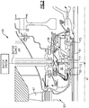
- FIG. 1 schematically illustrates a gas turbine engine 20.
- the gas turbine engine 20 disclosed herein is a two spool turbofan engine that generally incorporates a fan section 22, a compressor section 24, a combustor section 26 and a turbine section 28.
- Alternative engines might include an augmenter section (not shown) among other systems or features.
- the fan section 22 drives air along a bypass flow path B while the compressor section 24 drives air along a core flow path C for compression and communication into the combustor section 26.
- the hot combustion gases generated in the combustor section 26 are expanded through the turbine section 28.
- FIG. 1 schematically illustrates a gas turbine engine 20.
- the gas turbine engine 20 disclosed herein is a two spool turbofan engine that generally incorporates a fan section 22, a compressor section 24, a combustor section 26 and a turbine section 28.
- Alternative engines might include an augmenter section (not shown) among other systems or features.
- the fan section 22 drives air along a bypass flow path B while the compressor section 24 drives
- the gas turbine engine 20 generally includes a low speed spool 30 and a high speed spool 32 mounted for rotation about an engine centerline longitudinal axis A relative to an engine static structure 36 via several bearing structures 38. It should be understood that various bearing structures 38 at various locations may alternatively or additionally be provided.
- the low speed spool 30 generally includes an inner shaft 40 that interconnects a fan 42, a low pressure compressor 44 and a low pressure turbine 46.
- the inner shaft 40 can be connected to the fan 42 through a geared architecture 48 to drive the fan 42 at a lower speed than the low speed spool 30.
- the high speed spool 32 includes an outer shaft 50 that interconnects a high pressure compressor 52 and a high pressure turbine 54.
- the inner shaft 40 and the outer shaft 50 are supported at a plurality of points by bearing structures 38 positioned within the engine static structure 36.
- bearing structures 38 include at least a #1 bearing structure 38-1 forward of the geared architecture 48 and a #2 bearing structure 38-2 located aft of the geared architecture 48.
- a combustor 56 is arranged between the high pressure compressor 52 and the high pressure turbine 54.
- a mid-turbine frame 57 of the engine static structure 36 is arranged generally between the high pressure turbine 54 and the low pressure turbine 46.
- the mid-turbine frame 57 can support one or more bearing structures 38 in the turbine section 28.
- the inner shaft 40 and the outer shaft 50 are concentric and rotate via the bearing structures 38 about the engine centerline longitudinal axis A which is collinear with their longitudinal axes.
- the inner shaft 40 and the outer shaft 50 can be either co-rotating or counter-rotating with respect to one another.
- the core airflow C is compressed by the low pressure compressor 44 and the high pressure compressor 52, is mixed with fuel and burned in the combustor 56, and is then expanded over the high pressure turbine 54 and the low pressure turbine 46.
- the mid-turbine frame 57 includes airfoils 59 which are in the core airflow path.
- the high pressure turbine 54 and the low pressure turbine 46 rotationally drive the respective high speed spool 32 and the low speed spool 30 in response to the expansion.
- the gas turbine engine 20 is a high-bypass geared aircraft engine.
- the gas turbine engine 20 bypass ratio is greater than about six (6:1).
- the geared architecture 48 of the example gas turbine engine 20 includes an epicyclic gear train, such as a planetary gear system or other gear system.
- the example epicyclic gear train has a gear reduction ratio of greater than about 2.3.
- the geared architecture 48 enables operation of the low speed spool 30 at higher speeds which can increase the operational efficiency of the low pressure compressor 44 and low pressure turbine 46 and render increased pressure in a fewer number of stages.
- the low pressure turbine 46 pressure ratio is pressure measured prior to inlet of low pressure turbine 46 as related to the pressure at the outlet of the low pressure turbine 46 prior to an exhaust nozzle of the gas turbine engine 20.
- the bypass ratio of the gas turbine engine 20 is greater than about ten (10:1)
- the fan diameter is significantly larger than that of the low pressure compressor 44
- the low pressure turbine 46 has a pressure ratio that is greater than about 5 (5:1).
- the geared architecture 48 of this embodiment is an epicyclic gear train with a gear reduction ratio of greater than about 2.5:1. It should be understood, however, that the above parameters are only exemplary of one embodiment of a geared architecture engine and that the present disclosure is applicable to other gas turbine engines including direct drive turbofans.
- a significant amount of thrust is provided by a bypass flow B due to the high bypass ratio.
- the fan section 22 of the gas turbine engine 20 is designed for a particular flight conditiontypically cruise at about 0.8 Mach and about 35,000 feet. This flight condition, with the gas turbine engine 20 at its best fuel consumption, is also known as bucket cruise Thrust Specific Fuel Consumption (TSFC).
- TSFC Thrust Specific Fuel Consumption
- Fan Pressure Ratio is the pressure ratio across a blade of the fan section 22 without the use of a Fan Exit Guide Vane system.
- the low Fan Pressure Ratio according to one non-limiting embodiment of the example gas turbine engine 20 is less than 1.45.
- Low Corrected Fan Tip Speed is the actual fan tip speed divided by an industry standard temperature correction of "T" / 518.7 0.5 .
- T represents the ambient temperature in degrees Rankine.
- the Low Corrected Fan Tip Speed according to one non-limiting embodiment of the example gas turbine engine 20 is less than about 1150 fps (351 m/s).
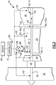
- Figure 2 illustrates a portion 100 of a gas turbine engine, such as the gas turbine engine 20.
- the portion 100 can include one or more bearing structures 38. Only one bearing structure 38 is depicted in Figure 2 to schematically illustrate its features, but this is in no way intended to limit this disclosure.
- the bearing structure 38 supports a shaft 61, such as the inner shaft 40 or the outer shaft 50, which supports a rotor assembly 63, such as a rotor assembly of the compressor section 24 or the turbine section 28, through a hub 65.
- the rotor assembly 63 carries at least one airfoil 67 for adding or extracting energy from the core airflow.
- the bearing structure 38 defines a bearing compartment BC that houses one or more bearings 71.
- the bearing compartment BC contains a lubricant for lubricating (and acting as a cooling medium to) the bearings 71.
- One or more seals 73 (two shown) contain the lubricant within the bearing compartment BC.
- the seals 73 of the bearing compartment BC must be pressurized to prevent the lubricant from leaking out during certain ground and flight conditions (both steady state and transient).
- a buffer system can be used to communicate buffer supply air to the bearing compartment BC in order to provide adequate pressurization of the seals 73 without exceeding material and/or lubricant temperature limitations. Example buffer systems that can be used for this and other purposes are detailed below.
- Figure 3 illustrates an example buffer system 60 that can communicate buffer supply air 62 to a portion of the gas turbine engine 20, such as to one or more bearing compartments BC.
- bearing compartments BC-1, BC-2, BC-3, BC-4(a), BC-4(b) and BC-5 can be fed with buffer supply air 62.
- the buffer supply air 62 pressurizes the bearing compartments BC and can maintain the bearing compartments BC at an acceptable temperature.
- this example illustrates communication of the buffer supply air 62 to multiple bearing compartments BC-1 through BC-5 to provide adequate bearing compartment seal pressurization to prevent lubricant leakage, buffer supply air 62 could be communicated to only a single bearing compartment or could be communicated for anti-icing, ventilation, cooling and other purposes.
- the buffer system 60 includes a first bleed air supply 64 and a second bleed air supply 66.
- the buffer system 60 is a dual supply system.
- the first bleed air supply 64 is a low pressure bleed air supply and the second bleed air supply 66 is a high pressure bleed air supply that includes a pressure that is greater than the pressure of the first bleed air supply 64.
- the first bleed air supply 64 can be sourced from the fan section 22, the low pressure compressor 44 or the high pressure compressor 52. In the illustrated non-limiting example, the first bleed air supply 64 is sourced from an upstream stage of the high pressure compressor 52. However, the first bleed air supply 64 could be sourced from any location that is upstream from the second bleed air supply 66.
- the second bleed air supply 66 can be sourced from the high pressure compressor 52, such as from a middle or downstream stage of the high pressure compressor 52. The second bleed air supply 66 could also be sourced from the low pressure compressor 44 or the fan section 22 depending on from where the first bleed air supply 64 is sourced.
- the buffer system 60 can also include a valve 68 that is in communication with both the first bleed air supply 64 and the second bleed air supply 66. Although shown schematically, the first bleed air supply 64 and the second bleed air supply 66 can be in fluid communication with the valve 68 via buffer tubing, conduits, or other passageways. Check valves may also be used to prevent the second bleed air supply 66 from backflowing into the first bleed air supply 64.
- the valve 68 can select between the first bleed air supply 64 and the second bleed air supply 66 to communicate the buffer supply air 62 to a desired portion(s) of the gas turbine engine 20.
- the buffer supply air 62 that is communicated is either the first bleed air supply 64 or the second bleed air supply 66 depending on which air supply is ultimately selected by the valve 68, as is further discussed below.
- the determination of whether to communicate the first bleed air supply 64 or the second bleed air supply 66 as the buffer supply air 62 is based on a power condition of the gas turbine engine 20.
- the term "power condition" as used in this disclosure generally refers to an operability condition of the gas turbine engine 20.
- Gas turbine engine power conditions can include low power conditions and high power conditions.
- Example low power conditions include, but are not limited to, ground operation, ground idle, and descent idle.
- Example high power conditions include, but are not limited to, takeoff, climb, and cruise conditions. It should be understood that other power conditions are also contemplated as within the scope of this disclosure.
- the valve 68 communicates the first bleed air supply 64 (which is a relatively lower pressure bleed air supply) as the buffer supply air 62 in response to identifying a high power condition of a gas turbine engine 20.
- the second bleed air supply 66 (which is a relatively higher pressure bleed air supply) is selected by the valve 68 and communicated as the buffer supply air 62 in response to detecting a low power condition of the gas turbine engine 20.
- Both the first bleed air supply 64 and the second bleed air supply 66 are intended to maintain the same minimum pressure delta across the bearing compartment seals. Low power conditions require a higher stage pressure source to contain the lubricant within the bearing compartment, while high power conditions require a lower stage pressure source.
- the buffer system 60 can use the lowest possible compressor stage to meet pressure requirements in order to minimize supply temperature and any performance impact to the gas turbine engine 20.
- the valve 68 can be a passive valve.
- a passive valve operates like a pressure regulator that can switch between two or more sources without being commanded to do so by a controller, such as an engine control (EEC).
- EEC engine control
- the valve 68 of this example uses only a single input which is directly measured to switch between the first bleed air supply 64 and the second bleed air supply 66.
- the valve 68 could also be a controller based valve.
- the buffer system 60 can include a controller 70 in communication with the valve 68 for selecting between the first bleed air supply 64 and the second bleed air supply 66.
- the controller 70 is programmed with the necessary logic for selecting between the first bleed air supply 64 and the second bleed air supply 66 in response to detecting a pre-defined power condition of the gas turbine engine 20.
- the controller 70 could also be programmed with multiple inputs.
- a sensor 99 detects a power condition of the gas turbine engine 20 and communicates a signal to the controller 70 to command modulation of the valve 68 between the first bleed air supply 64 and the second bleed air supply 66.
- the valve 68 could also be modulated to an intermediate level to intermix the first bleed air supply 64 and the second bleed air supply 66.
- this view is highly schematic. It should be understood that the sensor 99 and the controller 70 can be programmed to detect any power condition. Also, the sensor 99 can be replaced by any control associated with the gas turbine engine 20 or an associated aircraft. Also, although shown as a separate feature, the controller functionality could be incorporated into the valve 68.
- FIG 4 illustrates another example buffer system 160 that can communicate buffer supply air 162 to provide adequate bearing compartment seal pressurization at an acceptable temperature.
- the buffer supply air 162 can also be used for additional purposes such as anti-icing and ventilation or for other cooling requirements of the gas turbine engine 20.
- the buffer system 160 includes a first bleed air supply 164, a second bleed air supply 166 and an ejector 172.
- the first bleed air supply 164 can be augmented by the ejector 172 to prepare the buffer supply air 162 for communication to a portion of the gas turbine engine 20, such as a bearing compartment BC (schematically shown by Figure 4 ).
- the ejector 172 can add pressure (using a relatively small amount of the second bleed air supply 166) to the first bleed air supply 164 to prepare the buffer supply air 162 for communication to an appropriate location of a gas turbine engine 20.
- the ejector 172 can mix the first bleed air supply 164 of a first pressure with the second bleed air supply 166 of a second higher pressure to render the buffer supply air 162 of an intermediate pressure to the first bleed air supply 164 and the second bleed air supply 166.
- the second bleed air supply 166 which is a higher pressure air than the first bleed air supply 164, can be communicated to the ejector 172 to power the ejector 172.
- the first bleed air supply 164 can be sourced from the fan section 22, the low pressure compressor 44 or the high pressure compressor 52.
- the second bleed air supply 166 can be sourced from a middle or downstream stage of the high pressure compressor 52, or can include diffuser air.
- the second bleed air supply 166 could also be sourced from the low pressure compressor 44 or the fan section 22 depending on from where the first bleed air supply 164 is sourced.
- Augmentation of the first bleed air supply 164 prepares the buffer supply air 162 at an adequate pressure and temperature to pressurize the bearing compartment(s) BC.
- the determination of whether or not to augment the first bleed air supply 164 with the ejector 172 is based on a power condition of the gas turbine engine 20.
- Gas turbine engine power conditions can include low power conditions and high power conditions.
- Example low power conditions include, but are not limited to, ground operation, ground idle and descent idle.
- Example high power conditions include, but are not limited to, takeoff, climb, and cruise conditions. It should be understood that other power conditions are also contemplated as within the scope of this disclosure.
- the first bleed air supply 164 is augmented by the ejector 172 in response to detecting a low power condition of the gas turbine engine 20 in order to communicate a buffer supply air 162 having adequate pressurization.
- the amount of augmentation performed on the first bleed air supply 164 can vary depending upon the type of power condition that is detected and the pressure requirements of the bearing compartment(s) BC.
- the first bleed air supply 164 is not augmented by the ejector 172 in response to detection of a high power condition of the gas turbine engine 20. In other words, the first bleed air supply 164 can be communicated as the buffer supply air 162 without any augmentation in response to some power conditions.
- the buffer system 160 can include a controller 170 in communication with the ejector 172 for determining whether or not to augment the first bleed air supply 164.
- the controller 170 is programmed with the necessary logic for making this determination in response to detecting a pre-defined power condition of the gas turbine engine 20.
- a sensor 199 detects a power condition of the gas turbine engine 20 and communicates a signal to the controller 170 to command the ejector 172 to augment the first bleed air supply 64.
- this view is highly schematic. It should be understood that the sensor 199 and the controller 170 can be programmed to detect any power condition. Also, the sensor 199 can be replaced by any control associated with the gas turbine engine 20 or an associated aircraft. Also, although shown as a separate feature, the controller 170 functionality could be incorporated into the ejector 172.
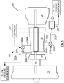
- Figure 5 illustrates an example buffer system 260 according to an embodiment of the invention.
- the buffer system 260 is a two-circuit, multi-source buffer system that includes at least a first circuit 274 and a second circuit 276. Additional circuits could also be incorporated.
- Low pressure requirements of the gas turbine engine 20 can be fed with a first buffer supply air 262A from the first circuit 274, while high pressure requirements of the gas turbine engine 20 can be buffered with a second buffer supply air 262B from the second circuit 276.
- the first circuit 274 can buffer a first portion(s) of the gas turbine engine 20, while the second circuit 276 can buffer a second, different portion(s).
- Example components subject to low pressure requirements include bearing compartments in low pressure regions of the gas turbine engine 20, such as front or rear bearing compartments.
- Example components subject to high pressure requirements include bearing compartments in high pressure regions of the gas turbine engine 20, such as mid-engine bearing compartments.
- the first circuit 274 is similar to the buffer system 60 of Figure 3 and includes a first bleed air supply 264A, a second bleed air supply 266A and a valve 268A.
- the second circuit 276 includes a first bleed air supply 264B, a second bleed air supply 266B, a valve 268B and a conditioning device 280.
- the conditioning device 280 cools the second buffer supply air 262B to an acceptable temperature for addressing higher pressure requirements.
- the conditioning device could include an air-to-air heat exchanger, a fuel-to-air heat exchanger, or any other suitable heater exchanger.
- the conditioning device 280 could also be a device other than a heat exchanger.
- the second bleed air supply 266A of the first circuit 274 can be common to the first bleed air supply 264B of the second circuit 276. These sources can also be completely separate.
- the second bleed air supplies 266A, 266B are communicated as the buffer supply airs 262A, 262B for low power conditions of the gas turbine engine 20 and the first bleed air supplies 264A, 264B are communicated as the buffer supply airs 262A, 262B in response to high power conditions of the gas turbine engine 20.
- Example low power conditions include, but are not limited to, ground operation, ground idle and flight idle conditions.
- Example high power conditions include, but are not limited to, takeoff, climb, and cruise conditions. It should be understood that other power conditions are also contemplated as within the scope of this disclosure.
- the valves 268A, 268B select and communicate the first bleed air supplies 264A, 264B (which are relatively lower pressure bleed air supplies) as the buffer supply airs 262A, 262B in response to identifying a high power condition of a gas turbine engine 20.
- the second bleed air supplies 266A, 266B (which are relatively higher pressure bleed air supplies) are selected by the valves 268A, 268B and communicated as the buffer supply airs 262A, 262B in response to detecting a low power condition of the gas turbine engine 20. Both the lower bleed air supplies and the higher bleed air supplies are intended to maintain the same minimum pressure delta across the bearing compartment seals.
- the buffer system 260 can use the lowest possible compressor stage to meet the pressure requirements in order to minimize supply temperature and any performance impact to the gas turbine engine 20.
- the buffer system 260 can also include a controller 270 in communication with the valves 268A, 268B for selectively switching between the first bleed air supplies 264A, 264B and the second bleed air supplies 266A, 266B.
- a single controller or multiple controllers could be utilized.
- the controller 270 can also command operation of the conditioning device 280 of the second circuit 276 for cooling the buffer supply air 262B. Alternatively, separate controllers can be used to control each of the first circuit 274, the second circuit 276 and the conditioning device 280.
Landscapes
- Engineering & Computer Science (AREA)
- Chemical & Material Sciences (AREA)
- Combustion & Propulsion (AREA)
- Mechanical Engineering (AREA)
- General Engineering & Computer Science (AREA)
- Engine Equipment That Uses Special Cycles (AREA)
- Structures Of Non-Positive Displacement Pumps (AREA)
Claims (13)
- Gasturbinentriebwerk (20), das Folgendes umfasst:ein Puffersystem (260), das einen ersten Kreislauf (274) einschließt, der eine erste Pufferzufuhrluft (262A) an eine erste Lagerkammer (Bearing Compartment, BC) des Gasturbinentriebwerks kommuniziert;wobei der erste Kreislauf eine erste Abluftzufuhr (264A), eine zweite Abluftzufuhr (266A) und ein Ventil (268A) einschließt;dadurch gekennzeichnet, dass das Puffersystem ferner einen zweiten Kreislauf (276) umfasst, der eine zweite Pufferzufuhrluft (262B) an eine zweite Lagerkammer (BC) des Gasturbinentriebwerks kommuniziert;wobei der zweite Kreislauf eine erste Abluftzufuhr (264B), eine zweite Abluftzufuhr (266B), ein Ventil (268B) und eine Klimatisierungsvorrichtung (280) einschließt.
- Gasturbinentriebwerk (20) nach Anspruch 1, wobei die erste Lagerkammer (BC) niedrigen Druckanforderungen ausgesetzt ist und die zweite Lagerkammer (BC) hohen Druckanforderungen ausgesetzt ist.
- Gasturbinentriebwerk (20) nach einem der vorhergehenden Ansprüche, umfassend mindestens eine Steuerung (270) in Kommunikation mit jedem von dem ersten Kreislauf (274) und dem zweiten Kreislauf (276).
- Gasturbinentriebwerk nach Anspruch 3, wobei die mindestens eine Steuerung eine Verstärkung von Pufferzufuhrluft für mindestens einen von dem ersten Kreislauf und dem zweiten Kreislauf regeln soll.
- Gasturbinentriebwerk nach einem der vorhergehenden Ansprüche, ferner umfassend:einen Verdichterbereich;eine Brennkammer in Fluidkommunikation mit dem Verdichterbereich;einen Turbinenbereich in Fluidkommunikation mit der Brennkammer.
- Gasturbinentriebwerk nach Anspruch 5, wobei das Gasturbinentriebwerk:
ein Hochbypassflugzeugtriebwerk mit Getriebe ist, das ein Bypass-Verhältnis von mehr als sechs aufweist. - Gasturbinentriebwerk nach Anspruch 5 oder 6, wobei das Gasturbinentriebwerk ein niedriges Lüfterdruckverhältnis von weniger als 1,45 einschließt.
- Verfahren zum Kühlen eines Abschnitts eines Gasturbinentriebwerks (20), wobei das Verfahren Folgendes umfasst:Ansteuern einer Lagerkammer (BC), die einer ersten Druckanforderung des Gasturbinentriebwerks ausgesetzt ist, mit einer ersten Pufferzufuhrluft (262A) von einem ersten Kreislauf (274) eines Puffersystems (260);Ansteuern einer Lagerkammer (BC), die einer zweiten Druckanforderung des Gasturbinentriebwerks ausgesetzt ist, mit einer zweiten Pufferzufuhrluft (262B) von einem zweiten Kreislauf (276) des Puffersystems;wobei der erste Kreislauf eine erste Abluftzufuhr (264A), eine zweite Abluftzufuhr (266A) und ein Ventil (268A) einschließt; undwobei der zweite Kreislauf eine erste Abluftzufuhr (264B), eine zweite Abluftzufuhr (266B), ein Ventil (268B) und eine Klimatisierungsvorrichtung (280) einschließt.
- Verfahren nach Anspruch 8, wobei die Lagerkammer (BC), die der zweiten Druckanforderung ausgesetzt ist, von der Lagerkammer (BC), die der ersten Druckanforderung ausgesetzt ist, getrennt positioniert ist.
- Verfahren nach Anspruch 8 oder 9, umfassend den Schritt des Identifizierens eines Leistungszustands des Gasturbinentriebwerks (20) vor den Schritten des Ansteuerns.
- Verfahren nach Anspruch 10, das den folgenden Schritt umfasst:Kommunizieren von Abluftzufuhren mit niedrigem Druck als erste Pufferluftzufuhr (262A) und zweite Pufferluftzufuhr (262B) als Reaktion auf ein Identifizieren eines Zustands mit hoher Leistung; undKommunizieren von Abluftzufuhren mit hohem Druck als erste Pufferluftzufuhr (262A) und zweite Pufferluftzufuhr (262B) als Reaktion auf ein Identifizieren eines Zustands mit niedriger Leistung.
- Verfahren nach Anspruch 9, 10 oder 11, das den folgenden Schritt umfasst:
Kühlen der zweiten Pufferzufuhrluft (262B) vor dem Schritt des Ansteuerns der Lagerkammer (BC), die der zweiten Druckanforderung ausgesetzt ist. - Verfahren nach einem der Ansprüche 9 bis 12, das den folgenden Schritt umfasst:
Verstärken von einer von der ersten Pufferluftzufuhr (262A) und der zweiten Pufferluftzufuhr (262B) mit einer Ausstoßvorrichtung (172).
Applications Claiming Priority (2)
| Application Number | Priority Date | Filing Date | Title |
|---|---|---|---|
| US13/362,349 US8769962B2 (en) | 2012-01-31 | 2012-01-31 | Multi-circuit buffer system for a gas turbine engine |
| PCT/US2013/021641 WO2013154633A2 (en) | 2012-01-31 | 2013-01-16 | Gas turbine engine buffer system |
Publications (3)
| Publication Number | Publication Date |
|---|---|
| EP2809901A2 EP2809901A2 (de) | 2014-12-10 |
| EP2809901A4 EP2809901A4 (de) | 2015-10-21 |
| EP2809901B1 true EP2809901B1 (de) | 2019-10-23 |
Family
ID=48869053
Family Applications (1)
| Application Number | Title | Priority Date | Filing Date |
|---|---|---|---|
| EP13775885.0A Active EP2809901B1 (de) | 2012-01-31 | 2013-01-16 | Puffersystem für gasturbinenmotor und entsprechendes kühlverfahren |
Country Status (3)
| Country | Link |
|---|---|
| US (3) | US8769962B2 (de) |
| EP (1) | EP2809901B1 (de) |
| WO (1) | WO2013154633A2 (de) |
Families Citing this family (30)
| Publication number | Priority date | Publication date | Assignee | Title |
|---|---|---|---|---|
| WO2015030907A1 (en) | 2013-08-26 | 2015-03-05 | Hamilton Sundstrand Corporation | Variable pressure air supply |
| EP3084180B1 (de) * | 2013-12-16 | 2020-04-01 | United Technologies Corporation | Übertragungslager für getriebefan |
| US9580180B2 (en) | 2014-03-07 | 2017-02-28 | Honeywell International Inc. | Low-pressure bleed air aircraft environmental control system |
| US10054051B2 (en) * | 2014-04-01 | 2018-08-21 | The Boeing Company | Bleed air systems for use with aircraft and related methods |
| US9810158B2 (en) * | 2014-04-01 | 2017-11-07 | The Boeing Company | Bleed air systems for use with aircraft and related methods |
| US9869190B2 (en) | 2014-05-30 | 2018-01-16 | General Electric Company | Variable-pitch rotor with remote counterweights |
| US10472071B2 (en) * | 2014-07-09 | 2019-11-12 | United Technologies Corporation | Hybrid compressor bleed air for aircraft use |
| US10731502B2 (en) * | 2014-11-03 | 2020-08-04 | Raytheon Technologies Corporation | High pressure compressor rotor thermal conditioning using outer diameter gas extraction |
| US10072510B2 (en) | 2014-11-21 | 2018-09-11 | General Electric Company | Variable pitch fan for gas turbine engine and method of assembling the same |
| US10100744B2 (en) | 2015-06-19 | 2018-10-16 | The Boeing Company | Aircraft bleed air and engine starter systems and related methods |
| US10100653B2 (en) | 2015-10-08 | 2018-10-16 | General Electric Company | Variable pitch fan blade retention system |
| US10774752B2 (en) * | 2016-04-04 | 2020-09-15 | Raytheon Technologies Corporation | Integrated environmental control and buffer air system |
| US10344614B2 (en) | 2016-04-12 | 2019-07-09 | United Technologies Corporation | Active clearance control for a turbine and case |
| US10982595B2 (en) * | 2016-08-23 | 2021-04-20 | Raytheon Technologies Corporation | Heat exchanger for gas turbine engine mounted in intermediate case |
| US10422237B2 (en) * | 2017-04-11 | 2019-09-24 | United Technologies Corporation | Flow diverter case attachment for gas turbine engine |
| FR3078368B1 (fr) * | 2018-02-23 | 2021-05-28 | Safran Aircraft Engines | Turbomachine comportant un echangeur de chaleur dans la veine secondaire |
| GB201808852D0 (en) | 2018-05-31 | 2018-07-18 | Rolls Royce Plc | Gas turbine engine |
| US10954865B2 (en) | 2018-06-19 | 2021-03-23 | The Boeing Company | Pressurized air systems for aircraft and related methods |
| US11306614B2 (en) * | 2018-10-04 | 2022-04-19 | Rolls-Royce Corporation | Sump auxiliary vent system |
| US10774684B2 (en) * | 2018-10-24 | 2020-09-15 | Raytheon Technologies Corporation | Gas turbine engine seal assemblies |
| US11465757B2 (en) | 2018-12-06 | 2022-10-11 | The Boeing Company | Systems and methods to produce aircraft cabin supply air |
| US11274599B2 (en) | 2019-03-27 | 2022-03-15 | Pratt & Whitney Canada Corp. | Air system switching system to allow aero-engines to operate in standby mode |
| US11391219B2 (en) * | 2019-04-18 | 2022-07-19 | Pratt & Whitney Canada Corp. | Health monitor for air switching system |
| US11859563B2 (en) | 2019-05-31 | 2024-01-02 | Pratt & Whitney Canada Corp. | Air system of multi-engine aircraft |
| US11274611B2 (en) | 2019-05-31 | 2022-03-15 | Pratt & Whitney Canada Corp. | Control logic for gas turbine engine fuel economy |
| US11326525B2 (en) * | 2019-10-11 | 2022-05-10 | Pratt & Whitney Canada Corp. | Aircraft bleed air systems and methods |
| US11674435B2 (en) | 2021-06-29 | 2023-06-13 | General Electric Company | Levered counterweight feathering system |
| US11795964B2 (en) | 2021-07-16 | 2023-10-24 | General Electric Company | Levered counterweight feathering system |
| FR3140115B1 (fr) * | 2022-09-22 | 2024-10-04 | Safran Aircraft Engines | Pièce d'amortissement des déformations d'un carter de récupération d'huile, ensemble qui le comporte et turbomachine ainsi équipée |
| US20250027445A1 (en) * | 2023-07-21 | 2025-01-23 | Raytheon Technologies Corporation | Buffer air assembly for an aircraft engine |
Family Cites Families (22)
| Publication number | Priority date | Publication date | Assignee | Title |
|---|---|---|---|---|
| GB702931A (en) * | 1951-04-18 | 1954-01-27 | Bristol Aeroplane Co Ltd | Improvements in or relating to rotary machines comprising fluid compressing means |
| US3441045A (en) * | 1966-12-02 | 1969-04-29 | Boeing Co | Variable orifice nozzle mixing ejector |
| CA1034510A (en) * | 1975-10-14 | 1978-07-11 | Westinghouse Canada Limited | Cooling apparatus for split shaft gas turbine |
| US4550561A (en) * | 1980-03-20 | 1985-11-05 | The United States Of America As Represented By The Administrator Of The National Aeronautics And Space Administration | Method for improving the fuel efficiency of a gas turbine engine |
| US4561246A (en) | 1983-12-23 | 1985-12-31 | United Technologies Corporation | Bearing compartment for a gas turbine engine |
| US4645415A (en) | 1983-12-23 | 1987-02-24 | United Technologies Corporation | Air cooler for providing buffer air to a bearing compartment |
| US6393825B1 (en) * | 2000-01-25 | 2002-05-28 | General Electric Company | System for pressure modulation of turbine sidewall cavities |
| US6732502B2 (en) * | 2002-03-01 | 2004-05-11 | General Electric Company | Counter rotating aircraft gas turbine engine with high overall pressure ratio compressor |
| FR2898939B1 (fr) * | 2006-03-22 | 2008-05-09 | Snecma Sa | Systeme de degivrage d'un cone d'entree de turbomoteur pour aeronef |
| US7591631B2 (en) | 2006-06-30 | 2009-09-22 | United Technologies Corporation | Flow delivery system for seals |
| EP2066896B1 (de) | 2006-08-22 | 2016-10-05 | Rolls-Royce North American Technologies, Inc. | Gasturbinenmotor mit zwischengeschwindigkeitsverstärker |
| US20080115503A1 (en) * | 2006-11-16 | 2008-05-22 | Honeywell International, Inc. | Multi-port bleed system with variable geometry ejector pump |
| US8495883B2 (en) * | 2007-04-05 | 2013-07-30 | Siemens Energy, Inc. | Cooling of turbine components using combustor shell air |
| US20090313999A1 (en) * | 2008-05-13 | 2009-12-24 | Scott Hunter | Method and apparatus for controlling fuel in a gas turbine engine |
| US8146370B2 (en) * | 2008-05-21 | 2012-04-03 | Honeywell International Inc. | Turbine drive system with lock-up clutch and method |
| US20100092116A1 (en) | 2008-10-15 | 2010-04-15 | Honeywell International Inc. | Pressure balanced valve assembly and aircraft buffer cooler system employing the same |
| US20100162714A1 (en) * | 2008-12-31 | 2010-07-01 | Edward Claude Rice | Fuel nozzle with swirler vanes |
| US8142169B2 (en) * | 2009-01-06 | 2012-03-27 | General Electric Company | Variable geometry ejector |
| US8529189B2 (en) * | 2009-01-30 | 2013-09-10 | Honeywell International Inc. | Linear quadratic regulator control for bleed air system fan air valve |
| US8355854B2 (en) * | 2009-05-08 | 2013-01-15 | General Electric Company | Methods relating to gas turbine control and operation |
| US8516828B2 (en) | 2010-02-19 | 2013-08-27 | United Technologies Corporation | Bearing compartment pressurization and shaft ventilation system |
| US9359949B2 (en) * | 2011-02-17 | 2016-06-07 | Honeywell International Inc. | Distributed bleed system temperature management |
-
2012
- 2012-01-31 US US13/362,349 patent/US8769962B2/en active Active
-
2013
- 2013-01-16 WO PCT/US2013/021641 patent/WO2013154633A2/en not_active Ceased
- 2013-01-16 EP EP13775885.0A patent/EP2809901B1/de active Active
-
2014
- 2014-05-21 US US14/283,610 patent/US9816436B2/en active Active
-
2017
- 2017-10-26 US US15/794,175 patent/US10794275B2/en active Active
Non-Patent Citations (1)
| Title |
|---|
| None * |
Also Published As
| Publication number | Publication date |
|---|---|
| US9816436B2 (en) | 2017-11-14 |
| US20130192239A1 (en) | 2013-08-01 |
| US10794275B2 (en) | 2020-10-06 |
| EP2809901A4 (de) | 2015-10-21 |
| WO2013154633A3 (en) | 2013-12-05 |
| US20180045115A1 (en) | 2018-02-15 |
| WO2013154633A2 (en) | 2013-10-17 |
| US8769962B2 (en) | 2014-07-08 |
| EP2809901A2 (de) | 2014-12-10 |
| US20140318143A1 (en) | 2014-10-30 |
Similar Documents
| Publication | Publication Date | Title |
|---|---|---|
| US11098644B2 (en) | Gas turbine engine buffer system | |
| US11499476B2 (en) | Gas turbine engine buffer system | |
| EP2809901B1 (de) | Puffersystem für gasturbinenmotor und entsprechendes kühlverfahren | |
| EP2809911B1 (de) | Puffersystem für gasturbinenmotor | |
| US11560839B2 (en) | Gas turbine engine buffer system | |
| EP2809910B1 (de) | Gasturbinentriebwerkspuffersystem |
Legal Events
| Date | Code | Title | Description |
|---|---|---|---|
| PUAI | Public reference made under article 153(3) epc to a published international application that has entered the european phase |
Free format text: ORIGINAL CODE: 0009012 |
|
| 17P | Request for examination filed |
Effective date: 20140820 |
|
| AK | Designated contracting states |
Kind code of ref document: A2 Designated state(s): AL AT BE BG CH CY CZ DE DK EE ES FI FR GB GR HR HU IE IS IT LI LT LU LV MC MK MT NL NO PL PT RO RS SE SI SK SM TR |
|
| AX | Request for extension of the european patent |
Extension state: BA ME |
|
| DAX | Request for extension of the european patent (deleted) | ||
| A4 | Supplementary search report drawn up and despatched |
Effective date: 20150923 |
|
| RIC1 | Information provided on ipc code assigned before grant |
Ipc: F02C 7/14 20060101ALI20150917BHEP Ipc: F01D 25/18 20060101ALI20150917BHEP Ipc: F02C 6/08 20060101ALI20150917BHEP Ipc: F02C 1/00 20060101AFI20150917BHEP Ipc: F02C 7/12 20060101ALI20150917BHEP |
|
| RAP1 | Party data changed (applicant data changed or rights of an application transferred) |
Owner name: UNITED TECHNOLOGIES CORPORATION |
|
| GRAP | Despatch of communication of intention to grant a patent |
Free format text: ORIGINAL CODE: EPIDOSNIGR1 |
|
| STAA | Information on the status of an ep patent application or granted ep patent |
Free format text: STATUS: GRANT OF PATENT IS INTENDED |
|
| INTG | Intention to grant announced |
Effective date: 20181129 |
|
| GRAJ | Information related to disapproval of communication of intention to grant by the applicant or resumption of examination proceedings by the epo deleted |
Free format text: ORIGINAL CODE: EPIDOSDIGR1 |
|
| STAA | Information on the status of an ep patent application or granted ep patent |
Free format text: STATUS: REQUEST FOR EXAMINATION WAS MADE |
|
| GRAP | Despatch of communication of intention to grant a patent |
Free format text: ORIGINAL CODE: EPIDOSNIGR1 |
|
| STAA | Information on the status of an ep patent application or granted ep patent |
Free format text: STATUS: GRANT OF PATENT IS INTENDED |
|
| INTC | Intention to grant announced (deleted) | ||
| INTG | Intention to grant announced |
Effective date: 20190506 |
|
| GRAS | Grant fee paid |
Free format text: ORIGINAL CODE: EPIDOSNIGR3 |
|
| GRAA | (expected) grant |
Free format text: ORIGINAL CODE: 0009210 |
|
| STAA | Information on the status of an ep patent application or granted ep patent |
Free format text: STATUS: THE PATENT HAS BEEN GRANTED |
|
| AK | Designated contracting states |
Kind code of ref document: B1 Designated state(s): AL AT BE BG CH CY CZ DE DK EE ES FI FR GB GR HR HU IE IS IT LI LT LU LV MC MK MT NL NO PL PT RO RS SE SI SK SM TR |
|
| REG | Reference to a national code |
Ref country code: GB Ref legal event code: FG4D |
|
| REG | Reference to a national code |
Ref country code: CH Ref legal event code: EP |
|
| REG | Reference to a national code |
Ref country code: IE Ref legal event code: FG4D |
|
| REG | Reference to a national code |
Ref country code: DE Ref legal event code: R096 Ref document number: 602013062024 Country of ref document: DE |
|
| REG | Reference to a national code |
Ref country code: AT Ref legal event code: REF Ref document number: 1193879 Country of ref document: AT Kind code of ref document: T Effective date: 20191115 |
|
| REG | Reference to a national code |
Ref country code: NL Ref legal event code: MP Effective date: 20191023 |
|
| REG | Reference to a national code |
Ref country code: LT Ref legal event code: MG4D |
|
| PG25 | Lapsed in a contracting state [announced via postgrant information from national office to epo] |
Ref country code: ES Free format text: LAPSE BECAUSE OF FAILURE TO SUBMIT A TRANSLATION OF THE DESCRIPTION OR TO PAY THE FEE WITHIN THE PRESCRIBED TIME-LIMIT Effective date: 20191023 Ref country code: NL Free format text: LAPSE BECAUSE OF FAILURE TO SUBMIT A TRANSLATION OF THE DESCRIPTION OR TO PAY THE FEE WITHIN THE PRESCRIBED TIME-LIMIT Effective date: 20191023 Ref country code: SE Free format text: LAPSE BECAUSE OF FAILURE TO SUBMIT A TRANSLATION OF THE DESCRIPTION OR TO PAY THE FEE WITHIN THE PRESCRIBED TIME-LIMIT Effective date: 20191023 Ref country code: LV Free format text: LAPSE BECAUSE OF FAILURE TO SUBMIT A TRANSLATION OF THE DESCRIPTION OR TO PAY THE FEE WITHIN THE PRESCRIBED TIME-LIMIT Effective date: 20191023 Ref country code: PT Free format text: LAPSE BECAUSE OF FAILURE TO SUBMIT A TRANSLATION OF THE DESCRIPTION OR TO PAY THE FEE WITHIN THE PRESCRIBED TIME-LIMIT Effective date: 20200224 Ref country code: FI Free format text: LAPSE BECAUSE OF FAILURE TO SUBMIT A TRANSLATION OF THE DESCRIPTION OR TO PAY THE FEE WITHIN THE PRESCRIBED TIME-LIMIT Effective date: 20191023 Ref country code: BG Free format text: LAPSE BECAUSE OF FAILURE TO SUBMIT A TRANSLATION OF THE DESCRIPTION OR TO PAY THE FEE WITHIN THE PRESCRIBED TIME-LIMIT Effective date: 20200123 Ref country code: PL Free format text: LAPSE BECAUSE OF FAILURE TO SUBMIT A TRANSLATION OF THE DESCRIPTION OR TO PAY THE FEE WITHIN THE PRESCRIBED TIME-LIMIT Effective date: 20191023 Ref country code: LT Free format text: LAPSE BECAUSE OF FAILURE TO SUBMIT A TRANSLATION OF THE DESCRIPTION OR TO PAY THE FEE WITHIN THE PRESCRIBED TIME-LIMIT Effective date: 20191023 Ref country code: NO Free format text: LAPSE BECAUSE OF FAILURE TO SUBMIT A TRANSLATION OF THE DESCRIPTION OR TO PAY THE FEE WITHIN THE PRESCRIBED TIME-LIMIT Effective date: 20200123 Ref country code: GR Free format text: LAPSE BECAUSE OF FAILURE TO SUBMIT A TRANSLATION OF THE DESCRIPTION OR TO PAY THE FEE WITHIN THE PRESCRIBED TIME-LIMIT Effective date: 20200124 |
|
| PG25 | Lapsed in a contracting state [announced via postgrant information from national office to epo] |
Ref country code: RS Free format text: LAPSE BECAUSE OF FAILURE TO SUBMIT A TRANSLATION OF THE DESCRIPTION OR TO PAY THE FEE WITHIN THE PRESCRIBED TIME-LIMIT Effective date: 20191023 Ref country code: IS Free format text: LAPSE BECAUSE OF FAILURE TO SUBMIT A TRANSLATION OF THE DESCRIPTION OR TO PAY THE FEE WITHIN THE PRESCRIBED TIME-LIMIT Effective date: 20200224 Ref country code: HR Free format text: LAPSE BECAUSE OF FAILURE TO SUBMIT A TRANSLATION OF THE DESCRIPTION OR TO PAY THE FEE WITHIN THE PRESCRIBED TIME-LIMIT Effective date: 20191023 |
|
| PG25 | Lapsed in a contracting state [announced via postgrant information from national office to epo] |
Ref country code: AL Free format text: LAPSE BECAUSE OF FAILURE TO SUBMIT A TRANSLATION OF THE DESCRIPTION OR TO PAY THE FEE WITHIN THE PRESCRIBED TIME-LIMIT Effective date: 20191023 |
|
| REG | Reference to a national code |
Ref country code: DE Ref legal event code: R097 Ref document number: 602013062024 Country of ref document: DE |
|
| PG2D | Information on lapse in contracting state deleted |
Ref country code: IS |
|
| PG25 | Lapsed in a contracting state [announced via postgrant information from national office to epo] |
Ref country code: RO Free format text: LAPSE BECAUSE OF FAILURE TO SUBMIT A TRANSLATION OF THE DESCRIPTION OR TO PAY THE FEE WITHIN THE PRESCRIBED TIME-LIMIT Effective date: 20191023 Ref country code: CZ Free format text: LAPSE BECAUSE OF FAILURE TO SUBMIT A TRANSLATION OF THE DESCRIPTION OR TO PAY THE FEE WITHIN THE PRESCRIBED TIME-LIMIT Effective date: 20191023 Ref country code: DK Free format text: LAPSE BECAUSE OF FAILURE TO SUBMIT A TRANSLATION OF THE DESCRIPTION OR TO PAY THE FEE WITHIN THE PRESCRIBED TIME-LIMIT Effective date: 20191023 Ref country code: EE Free format text: LAPSE BECAUSE OF FAILURE TO SUBMIT A TRANSLATION OF THE DESCRIPTION OR TO PAY THE FEE WITHIN THE PRESCRIBED TIME-LIMIT Effective date: 20191023 Ref country code: IS Free format text: LAPSE BECAUSE OF FAILURE TO SUBMIT A TRANSLATION OF THE DESCRIPTION OR TO PAY THE FEE WITHIN THE PRESCRIBED TIME-LIMIT Effective date: 20200223 |
|
| REG | Reference to a national code |
Ref country code: AT Ref legal event code: MK05 Ref document number: 1193879 Country of ref document: AT Kind code of ref document: T Effective date: 20191023 |
|
| PLBE | No opposition filed within time limit |
Free format text: ORIGINAL CODE: 0009261 |
|
| STAA | Information on the status of an ep patent application or granted ep patent |
Free format text: STATUS: NO OPPOSITION FILED WITHIN TIME LIMIT |
|
| PG25 | Lapsed in a contracting state [announced via postgrant information from national office to epo] |
Ref country code: SK Free format text: LAPSE BECAUSE OF FAILURE TO SUBMIT A TRANSLATION OF THE DESCRIPTION OR TO PAY THE FEE WITHIN THE PRESCRIBED TIME-LIMIT Effective date: 20191023 Ref country code: SM Free format text: LAPSE BECAUSE OF FAILURE TO SUBMIT A TRANSLATION OF THE DESCRIPTION OR TO PAY THE FEE WITHIN THE PRESCRIBED TIME-LIMIT Effective date: 20191023 Ref country code: IT Free format text: LAPSE BECAUSE OF FAILURE TO SUBMIT A TRANSLATION OF THE DESCRIPTION OR TO PAY THE FEE WITHIN THE PRESCRIBED TIME-LIMIT Effective date: 20191023 Ref country code: MC Free format text: LAPSE BECAUSE OF FAILURE TO SUBMIT A TRANSLATION OF THE DESCRIPTION OR TO PAY THE FEE WITHIN THE PRESCRIBED TIME-LIMIT Effective date: 20191023 |
|
| REG | Reference to a national code |
Ref country code: CH Ref legal event code: PL |
|
| 26N | No opposition filed |
Effective date: 20200724 |
|
| REG | Reference to a national code |
Ref country code: BE Ref legal event code: MM Effective date: 20200131 |
|
| PG25 | Lapsed in a contracting state [announced via postgrant information from national office to epo] |
Ref country code: LU Free format text: LAPSE BECAUSE OF NON-PAYMENT OF DUE FEES Effective date: 20200116 |
|
| PG25 | Lapsed in a contracting state [announced via postgrant information from national office to epo] |
Ref country code: SI Free format text: LAPSE BECAUSE OF FAILURE TO SUBMIT A TRANSLATION OF THE DESCRIPTION OR TO PAY THE FEE WITHIN THE PRESCRIBED TIME-LIMIT Effective date: 20191023 Ref country code: AT Free format text: LAPSE BECAUSE OF FAILURE TO SUBMIT A TRANSLATION OF THE DESCRIPTION OR TO PAY THE FEE WITHIN THE PRESCRIBED TIME-LIMIT Effective date: 20191023 Ref country code: BE Free format text: LAPSE BECAUSE OF NON-PAYMENT OF DUE FEES Effective date: 20200131 Ref country code: CH Free format text: LAPSE BECAUSE OF NON-PAYMENT OF DUE FEES Effective date: 20200131 Ref country code: LI Free format text: LAPSE BECAUSE OF NON-PAYMENT OF DUE FEES Effective date: 20200131 |
|
| PG25 | Lapsed in a contracting state [announced via postgrant information from national office to epo] |
Ref country code: IE Free format text: LAPSE BECAUSE OF NON-PAYMENT OF DUE FEES Effective date: 20200116 |
|
| PG25 | Lapsed in a contracting state [announced via postgrant information from national office to epo] |
Ref country code: TR Free format text: LAPSE BECAUSE OF FAILURE TO SUBMIT A TRANSLATION OF THE DESCRIPTION OR TO PAY THE FEE WITHIN THE PRESCRIBED TIME-LIMIT Effective date: 20191023 Ref country code: MT Free format text: LAPSE BECAUSE OF FAILURE TO SUBMIT A TRANSLATION OF THE DESCRIPTION OR TO PAY THE FEE WITHIN THE PRESCRIBED TIME-LIMIT Effective date: 20191023 Ref country code: CY Free format text: LAPSE BECAUSE OF FAILURE TO SUBMIT A TRANSLATION OF THE DESCRIPTION OR TO PAY THE FEE WITHIN THE PRESCRIBED TIME-LIMIT Effective date: 20191023 |
|
| PG25 | Lapsed in a contracting state [announced via postgrant information from national office to epo] |
Ref country code: MK Free format text: LAPSE BECAUSE OF FAILURE TO SUBMIT A TRANSLATION OF THE DESCRIPTION OR TO PAY THE FEE WITHIN THE PRESCRIBED TIME-LIMIT Effective date: 20191023 |
|
| REG | Reference to a national code |
Ref country code: DE Ref legal event code: R081 Ref document number: 602013062024 Country of ref document: DE Owner name: RAYTHEON TECHNOLOGIES CORPORATION (N.D.GES.D.S, US Free format text: FORMER OWNER: UNITED TECHNOLOGIES CORPORATION, FARMINGTON, CONN., US Ref country code: DE Ref legal event code: R081 Ref document number: 602013062024 Country of ref document: DE Owner name: RTX CORPORATION (N.D.GES.D. STAATES DELAWARE),, US Free format text: FORMER OWNER: UNITED TECHNOLOGIES CORPORATION, FARMINGTON, CONN., US |
|
| P01 | Opt-out of the competence of the unified patent court (upc) registered |
Effective date: 20230520 |
|
| PGFP | Annual fee paid to national office [announced via postgrant information from national office to epo] |
Ref country code: DE Payment date: 20241218 Year of fee payment: 13 |
|
| REG | Reference to a national code |
Ref country code: DE Ref legal event code: R081 Ref document number: 602013062024 Country of ref document: DE Owner name: RTX CORPORATION (N.D.GES.D. STAATES DELAWARE),, US Free format text: FORMER OWNER: RAYTHEON TECHNOLOGIES CORPORATION (N.D.GES.D.STAATES DELAWARE), ARLINGTON, VA, US |
|
| PGFP | Annual fee paid to national office [announced via postgrant information from national office to epo] |
Ref country code: GB Payment date: 20251217 Year of fee payment: 14 |
|
| PGFP | Annual fee paid to national office [announced via postgrant information from national office to epo] |
Ref country code: FR Payment date: 20251217 Year of fee payment: 14 |