EP2809475B1 - Verfahren zum erzeugen von ätzfähigen strukturen unter verwendung eines lasers mit einer wellenlänge im infrarotbereich - Google Patents
Verfahren zum erzeugen von ätzfähigen strukturen unter verwendung eines lasers mit einer wellenlänge im infrarotbereich Download PDFInfo
- Publication number
- EP2809475B1 EP2809475B1 EP13704739.5A EP13704739A EP2809475B1 EP 2809475 B1 EP2809475 B1 EP 2809475B1 EP 13704739 A EP13704739 A EP 13704739A EP 2809475 B1 EP2809475 B1 EP 2809475B1
- Authority
- EP
- European Patent Office
- Prior art keywords
- laser
- etch
- coating
- press plate
- press
- Prior art date
- Legal status (The legal status is an assumption and is not a legal conclusion. Google has not performed a legal analysis and makes no representation as to the accuracy of the status listed.)
- Active
Links
Images

Classifications
-
- B—PERFORMING OPERATIONS; TRANSPORTING
- B30—PRESSES
- B30B—PRESSES IN GENERAL
- B30B5/00—Presses characterised by the use of pressing means other than those mentioned in the preceding groups
- B30B5/04—Presses characterised by the use of pressing means other than those mentioned in the preceding groups wherein the pressing means is in the form of an endless band
-
- G—PHYSICS
- G03—PHOTOGRAPHY; CINEMATOGRAPHY; ANALOGOUS TECHNIQUES USING WAVES OTHER THAN OPTICAL WAVES; ELECTROGRAPHY; HOLOGRAPHY
- G03F—PHOTOMECHANICAL PRODUCTION OF TEXTURED OR PATTERNED SURFACES, e.g. FOR PRINTING, FOR PROCESSING OF SEMICONDUCTOR DEVICES; MATERIALS THEREFOR; ORIGINALS THEREFOR; APPARATUS SPECIALLY ADAPTED THEREFOR
- G03F7/00—Photomechanical, e.g. photolithographic, production of textured or patterned surfaces, e.g. printing surfaces; Materials therefor, e.g. comprising photoresists; Apparatus specially adapted therefor
- G03F7/0017—Photomechanical, e.g. photolithographic, production of textured or patterned surfaces, e.g. printing surfaces; Materials therefor, e.g. comprising photoresists; Apparatus specially adapted therefor for the production of embossing, cutting or similar devices; for the production of casting means
-
- B—PERFORMING OPERATIONS; TRANSPORTING
- B23—MACHINE TOOLS; METAL-WORKING NOT OTHERWISE PROVIDED FOR
- B23K—SOLDERING OR UNSOLDERING; WELDING; CLADDING OR PLATING BY SOLDERING OR WELDING; CUTTING BY APPLYING HEAT LOCALLY, e.g. FLAME CUTTING; WORKING BY LASER BEAM
- B23K26/00—Working by laser beam, e.g. welding, cutting or boring
- B23K26/352—Working by laser beam, e.g. welding, cutting or boring for surface treatment
- B23K26/355—Texturing
-
- B—PERFORMING OPERATIONS; TRANSPORTING
- B23—MACHINE TOOLS; METAL-WORKING NOT OTHERWISE PROVIDED FOR
- B23K—SOLDERING OR UNSOLDERING; WELDING; CLADDING OR PLATING BY SOLDERING OR WELDING; CUTTING BY APPLYING HEAT LOCALLY, e.g. FLAME CUTTING; WORKING BY LASER BEAM
- B23K26/00—Working by laser beam, e.g. welding, cutting or boring
- B23K26/352—Working by laser beam, e.g. welding, cutting or boring for surface treatment
- B23K26/3568—Modifying rugosity
- B23K26/3584—Increasing rugosity, i.e. roughening
-
- B—PERFORMING OPERATIONS; TRANSPORTING
- B23—MACHINE TOOLS; METAL-WORKING NOT OTHERWISE PROVIDED FOR
- B23K—SOLDERING OR UNSOLDERING; WELDING; CLADDING OR PLATING BY SOLDERING OR WELDING; CUTTING BY APPLYING HEAT LOCALLY, e.g. FLAME CUTTING; WORKING BY LASER BEAM
- B23K26/00—Working by laser beam, e.g. welding, cutting or boring
- B23K26/36—Removing material
- B23K26/361—Removing material for deburring or mechanical trimming
-
- B—PERFORMING OPERATIONS; TRANSPORTING
- B23—MACHINE TOOLS; METAL-WORKING NOT OTHERWISE PROVIDED FOR
- B23K—SOLDERING OR UNSOLDERING; WELDING; CLADDING OR PLATING BY SOLDERING OR WELDING; CUTTING BY APPLYING HEAT LOCALLY, e.g. FLAME CUTTING; WORKING BY LASER BEAM
- B23K26/00—Working by laser beam, e.g. welding, cutting or boring
- B23K26/36—Removing material
- B23K26/40—Removing material taking account of the properties of the material involved
-
- B—PERFORMING OPERATIONS; TRANSPORTING
- B29—WORKING OF PLASTICS; WORKING OF SUBSTANCES IN A PLASTIC STATE IN GENERAL
- B29C—SHAPING OR JOINING OF PLASTICS; SHAPING OF MATERIAL IN A PLASTIC STATE, NOT OTHERWISE PROVIDED FOR; AFTER-TREATMENT OF THE SHAPED PRODUCTS, e.g. REPAIRING
- B29C33/00—Moulds or cores; Details thereof or accessories therefor
- B29C33/38—Moulds or cores; Details thereof or accessories therefor characterised by the material or the manufacturing process
- B29C33/3842—Manufacturing moulds, e.g. shaping the mould surface by machining
- B29C33/3857—Manufacturing moulds, e.g. shaping the mould surface by machining by making impressions of one or more parts of models, e.g. shaped articles and including possible subsequent assembly of the parts
-
- B—PERFORMING OPERATIONS; TRANSPORTING
- B30—PRESSES
- B30B—PRESSES IN GENERAL
- B30B15/00—Details of, or accessories for, presses; Auxiliary measures in connection with pressing
- B30B15/06—Platens or press rams
- B30B15/062—Press plates
-
- B—PERFORMING OPERATIONS; TRANSPORTING
- B23—MACHINE TOOLS; METAL-WORKING NOT OTHERWISE PROVIDED FOR
- B23K—SOLDERING OR UNSOLDERING; WELDING; CLADDING OR PLATING BY SOLDERING OR WELDING; CUTTING BY APPLYING HEAT LOCALLY, e.g. FLAME CUTTING; WORKING BY LASER BEAM
- B23K2101/00—Articles made by soldering, welding or cutting
- B23K2101/20—Tools
-
- B—PERFORMING OPERATIONS; TRANSPORTING
- B23—MACHINE TOOLS; METAL-WORKING NOT OTHERWISE PROVIDED FOR
- B23K—SOLDERING OR UNSOLDERING; WELDING; CLADDING OR PLATING BY SOLDERING OR WELDING; CUTTING BY APPLYING HEAT LOCALLY, e.g. FLAME CUTTING; WORKING BY LASER BEAM
- B23K2103/00—Materials to be soldered, welded or cut
- B23K2103/50—Inorganic materials other than metals or composite materials
Definitions
- the invention relates to a method for producing etch-resistant structures (masks) on the surfaces of metallic pressing tools, namely endless press belts or press plates, by means of a laser, wherein a surface to be structured of the pressing tool is provided with a thermosensitive, etch-resistant coating and the laser structures of the etch-resistant coating burns out.
- Surface-structured large-sized endless press belts and press plates serve to provide plate or strip material for decorative or technical purposes with a surface structure.
- Surface structured plate or strip material is used, for example, in the furniture, flooring, construction and commercial vehicle industries (e.g., cargo bed trays).
- the plate material is made for example of various plastics. Also used are chipboard, plywood and MDF boards, which are coated with melamine-resin-impregnated films / papers / decors on the useful side (upper side) or on the underside. In the production of floors or commercial vehicle floors as well as building boards the melamine film / paper on the floor space additionally added a defined proportion of corundum materials to give the plate useful surface the required abrasion resistance.
- the surfaces of the panels are provided with decorative structures, such as wood, stone or other structures (bead-shaped, finely striated surface structures, etc.). Plates for the construction and commercial vehicle industry, for example, get technical geometric structures, such as diamonds, wells or corrugations (to effect, for example, skid resistance).
- the production of said pressing tools is carried out by applying a structured, etch-resistant mask on the surface to be structured of the Press plate or endless press belt and subsequent etching of the masked surface.
- the etch-resistant mask is usually printed on the surface. After etching, the mask is removed mechanically or electrolytically and the surface is cleaned. This process is repeated with different structures until the desired final structure has been achieved.
- the structured surface of the tool is then chrome-plated. This increases its service life, sets a defined degree of gloss of the plate surface to be produced and makes it easier to demould the plate (detachment of the pressing plate from the plate) after pressing.
- the structure of the surface of the pressing tool then corresponds to the negative of the surface structure to be produced on the plate material.
- the etching of the etch-resistant mask is usually carried out with a pressure roller.
- a disadvantage of conventional printing methods is that the printing process is imprecise. The color applied with the printing roller runs slightly, so that deviations in the mask from the graphically (often digitally) generated mask template can not be 100% avoided. On an already etched structure, this unfavorable influence increases all the more since the structure / contour flanks cause a low drainage of the printing ink.
- Another disadvantage is that the pressure roller can not transfer 100% of the mask with already etched surfaces (especially with deep etches) due to deep, sometimes very narrow structural elements. As a result, printing ink is sometimes missing in the structure valleys.
- the mask is imaged there only incompletely and can be etched in the subsequent etching process accordingly only incomplete in the surface.
- Further disadvantages are that it is not possible to print without rapport, that the printed image can not be defined and placed synchronously with the later produced décor and that drying times of the medium must be taken into account.
- a mask can also be produced by applying a photoresist. This is done by covering and exposing the photoresist applied to the die with a film which is the desired structural statement. The exposed (or unexposed) parts of the photoresist (positive / negative - photoresist) harden. After exposure, the uncured parts are chemically released from the tool surface. There remains a structured mask on the tool. The tool surface is then etched. This is followed by a cleaning and possibly another application of another mask followed by a further etching. This process is repeated with different masks until the desired final structure has been achieved in the surface of the pressing tool.
- the photographic process also has significant disadvantages.
- a problem with large die surfaces is that a film of multiple pieces of film must be assembled and glued together because there are not sufficiently large sized films available.
- At the adhesive edges develop during the development of the photoresist unwanted irritation, which must be manually laboriously corrected before etching.
- the photo chemicals pollute employees and the environment.
- the procurement and disposal of the photoresist is complex and expensive.
- the process is more labor intensive than a conventional printing process because additional operations are required (exposure, washing out of the uncured photoresist).
- the photographic process for continuous press belts is technically and economically not applicable.
- a problem underlying the invention is to provide a suitable method of the type mentioned above, in which the said problems do not occur or at least significantly reduced.
- the coating is burned out with a laser emitting with a wavelength in the infrared range between 780 nm and 1 mm. This could be because a laser beam with a wavelength in the infrared range couples very little into a metallic surface and is reflected to a very high degree (75% or more). Compared to other, in particular working in the UV laser, so little heat is dissipated in the surface of the pressing tool. Thus, while the laser can effectively burn out a structure from the etch-resistant coating, while at the same time leaving the properties of the metallic surface of the pressing tool unaffected.
- Is CO are suitable as special found 2 lasers, which generate a laser beam with a wavelength of 10.6 microns.
- laser beams of a YAG laser with wavelengths of 1064 nm, 946 nm, 1320 nm or 1444 nm have proven suitable for the method according to the invention.
- the method according to the invention is particularly suitable for producing etch-resistant structures on large-size press plates with a width and a length of more than 1 m each, the press plate being mounted on a table, in particular a vacuum table, and the laser above the press plate relative to the press plate is mobile.
- the table and / or the laser head can be moved at least in two directions.
- the inventive method is particularly suitable for very large press plates with a structured surface of a size of 6 m 2 or more or even 8 m 2 and above.
- inventive method can also be used for a continuous press belt, in which case the endless press belt is guided past a laser which can be moved in one direction.
- the laser head or the laser is typically adjustable in height and relative to the pressing tool and controllable.
- the laser beam is preferably focused by means of a lens, then the focus of the laser beam can be accurately positioned for optimum burnout of the coating.
- the laser processes the coating in different sections, which are in particular tiled.
- a head carrying the laser is positioned over a portion and the laser burns the structure out of the coating line by line and the contour of the structure introduced into the coating is bypassed by the laser beam at the end of the processing.
- the laser is preferably operated in pulsed mode, with the individual pulses being set in such a way that adjacent burnt-out points overlap as well as the points of adjacent lines. With a sufficiently powerful laser, the burnout can also take place in continuous wave mode.
- a solvent in particular with an alcohol, preferably with ethanol, wherein the ethanol can be denatured with 1% 2-butanone.
- the pressing tool provided with an etch-resistant coating is aligned with respect to the laser.
- the press plate is placed on a vacuum table and roughly aligned with guides arranged in the longitudinal direction of the table for support.
- the support carries a laser, the laser is mounted transversely to the support guides on the support and driven by a motor. After coarse alignment, the vacuum is activated, so that the press plate is fixed and just on the vacuum table.
- the table can be moved 2-dimensionally in the horizontal regardless of the support guides.
- two opposite reference points are marked on the press plate, which can be approached by the laser.
- first a first reference point on the press plate is approached and the position in the control of the laser head as such saved.
- the laser is moved across the long side of the table to the opposite reference point.
- the table is moved so that the laser hits the second reference point as it moves toward the support guides. This position is also stored in the control of the laser head.
- the laser is moved back to the first reference point. If the position of the first reference point has shifted due to the movement of the table, the entire procedure can be repeated until the reference points can be exactly approached with the laser control.
- the first reference point can be restarted by the control of the laser head, without the table is aligned again, due to the thus determinable offset between the original position of the first reference point and the then current position of the reference point of the control of the laser head or a computer for specifying the structure image, the position of the structure image or its tiles on the press plate can be calculated.
- the belt is positioned in a stand between two opposing drums.
- the frame is structurally designed so that a 100% degree runout of the belt is possible.
- the laser beam source is attached.
- the laser is positioned so that the laser beam is radial to the drum. As a result, a contour-sharp burnout of the structure is possible.
- the path control for the laser for burning out the coating according to the invention on a press plate can be done, for example, in tiles.
- the laser is moved to a position above an imaginary square or rectangular tile section on the press plate, preferably in a position perpendicular above the center of the tile. From this point, the laser burns line by line the desired structure from the coating.
- the laser is mounted pivotably in the support. After the laser has traversed all the rows of the tile and removed the coating at the desired locations, it is preferably once again traversed along the contours of the structures to be baked, to give the burned structure a smooth contour. Thereafter, the laser is moved to a position above another tile. From there, he then burns the structure into the coating of this imaginary tile.
- the tiling of the coating is due in particular to the possibilities of driving a laser. It is also conceivable to let the laser move line by line over the entire width (or length) of the press plate, if the support of the laser permits a correspondingly error-free guidance of the laser. This procedure then has the advantage that it can be dispensed with a pivotable mounting of the laser and the laser beam is always perpendicular to the coated press plate. It is also possible to dispense with a pivotable mounting of the laser, if the laser can be moved within the support in two directions parallel to the surface of the press plate, so that the laser beam within a tile is moved line by line and he always applies perpendicular to the press plate. Thus, the researcherbutede structure can be particularly sharp contour.
- the path control of the laser during burnout of the coating on an endless press belt takes place on the one hand transversely to the belt, wherein the belt is transported by a line feed after each passage of the laser.
- the tape is intermittently driven by the drums.
- the tape can also be moved longitudinally to the laser, wherein a line feed of the laser takes place in the transverse direction after each revolution of the laser.
- the burnout can also be spiral. In this case, the laser is controlled in a spiral burnout of the coating so that a gapless burned-out mask is formed.
- the method according to the invention is intended as part of a method for producing a structured surface of a press plate or press belt.
- the press sheet after it has been provided according to the invention with an etch-resistant structure, etched to produce a surface structure on the press plate or press belt. Subsequently, the etch-resistant structure is removed from the surface.
- These process steps can be repeated as required to produce a more complex surface structure of the pressed sheet, wherein in particular the etching depths of the individual etching steps are varied.
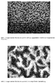
- Figures 1 and 2 show the result of Laserausbumbles with the inventive method in which the contours of the coating was traced with the laser.
- Figures 3 and 4 show the result of a Laserausbrennvons in which the contours of concernbumbleden contours were not pursued.
- pictures 1 and 2 it can be clearly seen in comparison to pictures 3 and 4 that the burnt-out structures have smooth edges and thus a clear contour.
Landscapes
- Engineering & Computer Science (AREA)
- Mechanical Engineering (AREA)
- Physics & Mathematics (AREA)
- Optics & Photonics (AREA)
- Plasma & Fusion (AREA)
- Manufacturing & Machinery (AREA)
- General Physics & Mathematics (AREA)
- Laser Beam Processing (AREA)
Description
- Die Erfindung betrifft ein Verfahren zum Erzeugen von ätzresistenten Strukturen (Masken) auf den Oberflächen von metallischen Presswerkzeugen, nämlich Endlospressbändern oder Pressblechen, mittels eines Lasers, wobei eine zu strukturierende Oberfläche des Presswerkzeugs mit einem thermosensitiven, ätzresistenten Überzug versehen wird und der Laser Strukturen aus dem ätzresistenten Überzug ausbrennt.
- Oberflächenstrukturierte großformatige Endlospressbänder und Pressbleche dienen dazu, Platten- oder Bandmaterial zu dekorativen oder technischen Zwecken mit einer Oberflächenstruktur zu versehen. Oberflächenstrukturiertes Platten- oder Bandmaterial wird beispielsweise in der Möbel-, Fußboden-, Bau- und Nutzfahrzeugindustrie ( z.B. Böden für Ladeflächen) verwendet.
- Das Plattenmaterial wird beispielsweise aus diversen Kunststoffen hergestellt. Ebenso kommen Span-, Sperrholz- und MDF-Platten zur Anwendung, die mit durch Melaminharz getränkten Filmen / Papieren / Dekoren auf der Nutzseite (Oberseite) oder der Unterseite beschichtet werden. Bei der Produktion von Fußböden oder Nutzfahrzeugböden ebenso wie bei Bauplatten wird dem Melaminfilm / -papier auf der Nutzfläche zusätzlich noch ein definierter Anteil von Korundmaterialien beigegeben, um der Plattennutzfläche die erforderliche Abriebfestigkeit zu verleihen. Für dekorative Anwendungen werden die Oberflächen der Platten mit dekorativen Strukturen, wie beispielsweise Holz-, Stein- oder anderen Strukturen (perlförmige, fein streifige Oberflächenstrukturen, etc.) versehen. Platten für die Bau- und Nutzfahrzeugindustrie erhalten beispielsweise technischgeometrische Strukturen, wie Rauten, Näpfchen oder Riffelungen (um beispielsweise Rutschfestigkeit zu bewirken).
- Bei der Herstellung des Plattenmaterials kommen Doppelband- und Heizpressen zum Einsatz. In den Heizpressen werden Einzelbleche oder kassettierte Blechstapel eingesetzt. In den Pressen werden die Prägnate (zu prägende Platten) unter definiertem Druck und Temperatur verpresst.
- Die Herstellung von den genannten Presswerkzeugen erfolgt durch Auftragen einer strukturierten, ätzresistenten Maske auf die zu strukturierende Oberfläche des Pressblechs oder Endlospressbandes und nachfolgendes Ätzen der maskierten Oberfläche. Die ätzresistente Maske wird üblicherweise auf die Oberfläche aufgedruckt. Nach dem Ätzen wird die Maske mechanisch oder elektrolytisch entfernt und die Oberfläche gereinigt. Dieser Vorgang wird so oft mit verschiedenen Strukturen wiederholt, bis die gewünschte Endstruktur erreicht wurde. In der Regel wird dann die strukturierte Oberfläche des Werkzeugs verchromt. Dadurch wird seine Lebensdauer erhöht, ein definierter Glanzgrad der herzustellenden Plattenoberfläche eingestellt und ein leichteres Entformen der Platte (Ablösen des Pressblechs von der Platte) nach dem Verpressen ermöglicht. Die Struktur der Oberfläche des Presswerkzeugs entspricht dann dem Negativ der auf dem Plattenmaterial zu erzeugenden Oberflächenstruktur.
- Das Aufdrucken der ätzresistenten Maske erfolgt üblicherweise mit einer Druckwalze. Ein Nachteil herkömmlicher Druckverfahren besteht darin, dass der Druckvorgang unpräzise ist. Die mit der Druckwalze aufgebrachte Farbe verläuft geringfügig, so dass Abweichungen in der Maske gegenüber der graphisch (oft digital) erstellten Maskenvorlage nicht zu 100% vermieden werden können. Auf einer bereits geätzten Struktur verstärkt sich dieser ungünstige Einfluss umso mehr, da die Struktur- / Konturflanken ein geringes Ablaufen der Druckfarbe bewirken. Ein anderer Nachteil besteht darin, dass die Druckwalze die Maske bei bereits geätzten Oberflächen (besonders bei tiefen Ätzungen) aufgrund tiefer, teilweise sehr enger Strukturelemente nicht zu 100% übertragen kann. In Folge dessen fehlt teilweise in den Strukturtälern Druckfarbe. Die Maske wird deshalb dort nur unvollständig abgebildet und kann im nachfolgenden Ätzvorgang dem entsprechend nur unvollständig in die Oberfläche geätzt werden. Weitere Nachteile bestehen darin, dass nicht rapportfrei bedruckt werden kann, dass das Druckbild nicht definiert und synchron zum später produzierten Dekor platziert werden kann und dass Trocknungszeiten des Mediums berücksichtigt werden müssen.
- Eine Maske kann auch durch Aufbringen eines Fotolackes erzeugt werden. Dies erfolgt indem der auf das Presswerkzeug aufgebrachte Fotolack mit einem Film, der die gewünschte Strukturaussage darstellt, abgedeckt und belichtet wird. Dabei härten die belichteten (oder die nicht belichteten) Teile des Fotolackes (positiv / negativ - Fotoresistlack) aus. Nach der Belichtung werden die nicht ausgehärteten Teile chemisch von der Werkzeugoberfläche gelöst. Es verbleibt eine strukturierte Maske auf dem Werkzeug. Die Werkzeugoberfläche wird dann geätzt. Anschließend erfolgt eine Reinigung und ggf. ein nochmaliges Aufbringen einer anderen Maske mit anschließender nochmaliger Ätzung. Dieser Vorgang wird so lange mit verschiedenen Masken wiederholt bis die gewünschte Endstruktur in der Oberfläche des Presswerkzeugs erreicht wurde. Auch das fototechnische Verfahren weist wesentliche Nachteile auf. So besteht bei großen Presswerkzeugoberflächen ein Problem darin, dass ein Film aus mehreren Filmstücken zusammengesetzt und geklebt werden muss, da keine ausreichend großformatigen Filme zur Verfügung stehen. An den Klebekanten entstehen bei der Entwicklung des Fotolackes unerwünschte Irritationen, die vor dem Ätzen aufwändig manuell korrigiert werden müssen. Des Weiteren belasten die Fotochemikalien Mitarbeiter und Umwelt. Darüber hinaus ist die Beschaffung und Entsorgung des Fotolackes aufwändig und teuer. Schließlich ist das Verfahren arbeitsintensiver als ein herkömmliches Druckverfahren, da zusätzliche Arbeitsgänge erforderlich sind (belichten, auswaschen des nicht ausgehärteten Fotolackes). Im Übrigen ist das fototechnische Verfahren für Endlospressbänder technisch und wirtschaftlich nicht anwendbar.
- Aus dem nächstliegenden Stand der Technik
DE 40 33 230 C2 (Basis für den Oberbegriff des Anspruchs 1) ist ein Verfahren der eingangs genannten Art zum Aufprägen von Prägegravuren auf großformatige Pressplatten oder Endlosbänder für die Oberflächenbehandlung von Bahnen oder Platten aus Kunststoff bekannt, bei dem das Pressblech oder Endlosband zunächst mit einer vollflächigen Trägerbahn aus Kunststoff, einer galvanischen Metallschicht oder einem ätzfesten Farbfilm überzogen wird. Mit Laserstrahlen wird dann eine nur die Dicke des Überzugs erfassende Prägestruktur erzeugt. Anschließend werden die metallblanken Stellen der Pressplatten und/oder der Endlosbänder einer Ätzbehandlung unterzogen. - Bisher sind Laserverfahren zur Herstellung ätzfähiger Masken für die industrielle Fertigung von Endlospressbändern oder Pressblechen noch nicht zur Anwendung gekommen. Dies könnte daran liegen, dass die digitale Darstellung einer Maske auf Großformaten ein Problem darstellt. Bei großformatigen Pressblechen von beispielsweise mehr als 8 m2 wird das auf dem Pressblech aufzubringende Strukturbild in verschiedene Felder, sogenannte Kacheln, unterteilt, deren Strukturbild nacheinander auf das Pressblech aufgebracht werden. Hiermit bleiben die zu verarbeitenden Datenmengen des Strukturbildes für die Steuerung des Laserkopfes handhabbar. Damit ein einheitliches Strukturbild entsteht, überlappen sich die einzelnen Kacheln. Ein Nachteil dieser Verfahrensweise ist aber, dass in den sich überlappenden Kachelbereichen unerwünschte, sichtbare Kanten in der Struktur der mit dem Laser ausgebrannten Maske entstehen. Des Weiteren sind aufgrund der Lasertechnologie die ausgebrannten Kanten der Struktur unsauber, es fehlt die erforderliche Kantenschärfe. Außerdem verbleiben auf der Werkzeugoberfläche nach dem Ätzen sichtbare Irritationen in der Struktur, die das Strukturbild nicht mehr verkaufsfähig machen.
- Somit besteht ein der Erfindung zugrunde liegendes Problem darin, ein geeignetes Verfahren der eingangs genannten Art zur Verfügung zu stellen, bei dem die genannten Probleme nicht oder zumindest deutlich reduziert auftreten.
- Diese Aufgabe wird mit einem Verfahren mit den Merkmalen des Anspruchs 1 gelöst.
- Es wurde überraschend festgestellt, dass das Auftreten von Kanteneffekten auf dem bearbeiteten Presswerkzeug vermieden werden können, wenn der Überzug mit einem Laser, der mit einer Wellenlänge im Infrarotbereich zwischen 780 nm und 1 mm emittiert, ausgebrannt wird. Dies könnte daran liegen, dass ein Laserstrahl mit einer Wellenlänge im Infrarotbereich nur sehr gering in eine metallische Oberfläche einkoppelt und zu einem sehr hohen Grad (75% oder mehr) reflektiert wird. Gegenüber anderen, insbesondere im UV-Bereich arbeitenden Lasern, wird damit wenig Wärme in der Oberfläche des Presswerkzeugs dissipiert. Somit kann der Laser zwar effektiv eine Struktur aus dem ätzresistenten Überzug ausbrennen, wobei er gleichzeitig die Eigenschaften der metallischen Oberfläche des Presswerkzeugs unbeeinflusst lässt.
- Als besonderes geeignet haben sich CO2-Laser herausgestellt, die einen Laserstrahl mit einer Wellenlänge von 10,6 µm erzeugen.
- Auch haben sich Laserstrahlen eines YAG-Lasers mit Wellenlängen von 1064 nm, 946 nm, 1320 nm oder 1444 nm als für das erfindungsgemäße Verfahren geeignet erwiesen.
- Das erfindungsgemäße Verfahren ist besonders geeignet zum Erzeugen von ätzresistenten Strukturen auf großformatigen Pressblechen mit einer Breite und einer Länge von jeweils mehr als 1 m, wobei das Pressblech auf einem Tisch, insbesondere einem Vakuumtisch, gelagert wird, und der Laser oberhalb des Pressblechs relativ zum Pressblech beweglich ist. Dabei sind wahlweise der Tisch und/oder der Laserkopf mindestens in zwei Richtungen verfahrbar. Das erfindungsgemäße Verfahren ist insbesondere auch für sehr große Pressbleche mit einer strukturierten Oberfläche einer Größe von 6 m2 oder mehr oder auch 8 m2 und darüber geeignet.
- Natürlich kann das erfindungsgemäße Verfahren auch für ein Endlospressband eingesetzt werden, wobei dann das Endlospressband an einem in einer Richtung verfahrbaren Laser vorbeigeführt wird.
- Bei beiden Anwendungen ist der Laserkopf bzw. der Laser typischerweise in seiner Höhe gegenüber dem Presswerkzeug verstellbar und steuerbar. Wenn der Laserstrahl vorzugsweise mittels einer Linse fokussiert ist, kann dann der Fokus des Laserstrahls für ein optimales Ausbrennen des Überzugs genau positioniert werden.
- Gerade bei großformatigen Pressblechen ist es sinnvoll und bei derzeitiger Steuerungstechnik sogar notwendig, dass der Laser den Überzug in verschiedenen Abschnitten, die insbesondere kachelartig sind, bearbeitet. In diesem Fall ist es besonders bevorzugt, wenn ein den Laser tragender Kopf über einem Abschnitt positioniert wird und der Laser zeilenweise die Struktur aus dem Überzug ausbrennt, und wobei die Kontur der in den Überzug eingebrachten Struktur am Ende der Bearbeitung mit dem Laserstrahl umfahren wird.
- Zum Ausbrennen des Überzugs wird der Laser vorzugsweise im Pulsbetrieb betrieben, wobei die einzelnen Pulse so gesetzt werden, dass sich nebeneinander liegende ausgebrannten Punkte ebenso wie die Punkte benachbarter Zeilen überlappen. Bei einem ausreichend leistungsfähigen Laser kann das Ausbrennen auch im Continuous-Wave-Betrieb erfolgen.
- Am Ende des erfindungsgemäßen Verfahrens ist es sinnvoll, das Presswerkzeug nach dem Ausbrennen des Überzugs mit einem Lösungsmittel zu reinigen, insbesondere mit einem Alkohol, vorzugsweise mit Ethanol, wobei das Ethanol mit 1% 2-Butanon vergällt sein kann.
- Bei einer möglichen Variante zur Vorbereitung des Laserausbrennverfahrens wird das mit einem ätzresistenten Überzug versehene Presswerkzeug gegenüber dem Laser ausgerichtet.
- Dies geschieht für ein Pressblech beispielsweise wie folgt: Das Pressblech wird auf einen Vakuumtisch gelegt und grob zu in Längsrichtung des Tisches angeordneten Führungen für einen Support ausgerichtet. Der Support trägt einen Laser, wobei der Laser quer zu den Supportführungen am Support beweglich gelagert und motorisch angetrieben ist. Nach erfolgter grober Ausrichtung wird das Vakuum aktiviert, so dass das Pressblech fixiert ist und eben auf dem Vakuumtisch liegt.
- Der Tisch kann unabhängig von den Supportführungen 2-dimensional in der Horizontalen bewegt werden. Zur Feinausrichtung des Pressblechs gegenüber den Supportführungen werden auf dem Pressblech zwei gegenüber liegende Referenzpunkte markiert, die von dem Laser angefahren werden können. Dazu wird zunächst ein erster Referenzpunkt auf dem Pressblech angefahren und die Position in der Steuerung des Laserkopfes als solcher gespeichert. Dann wird der Laser über die lange Tischseite zum gegenüberliegenden Referenzpunkt bewegt. Der Tisch wird so verschoben, dass der Laser bei seiner Bewegung in Richtung der Supportführungen den zweiten Referenzpunkt trifft. Auch diese Position wird in der Steuerung des Laserkopfes gespeichert. Dann wird der Laser wieder zum ersten Referenzpunkt zurückbewegt. Sollte sich die Lage des ersten Referenzpunktes durch das Verschieben des Tisches verschoben haben, kann die gesamte Prozedur solange wiederholt werden, bis dass mit der Lasersteuerung die Referenzpunkte genau angefahren werden können. Alternativ hierzu kann der erste Referenzpunkt von der Steuerung des Laserkopfes erneut angefahren werden, ohne dass der Tisch noch einmal ausgerichtet wird, wobei aufgrund des dadurch bestimmbaren Versatzes zwischen der ursprünglichen Lage des ersten Referenzpunktes und der dann aktuellen Lage des Referenzpunktes von der Steuerung des Laserkopfes oder eines Rechners zur Vorgabe des Strukturbildes die Lage des Strukturbildes bzw. seiner Kacheln auf dem Pressblech berechnet werden kann.
- Zur Vorbereitung eines mit einem ätzresistenten Überzug versehenen Endlospressband wird das Band in einem Ständerwerk zwischen zwei gegenüberliegenden Trommeln positioniert. Das Ständerwerk ist konstruktiv so ausgelegt, dass ein 100%iger Gradeauslauf des Bandes möglich ist. Gegenüber einer der Trommeln wird die Laserstrahlquelle angebracht. Die Positionierung des Lasers erfolgt so, dass der Laserstrahl radial zur Trommel verläuft. Dadurch wird ein konturscharfes Ausbrennen der Struktur möglich.
- Die Wegesteuerung für den Laser zum erfindungsgemäßen Ausbrennen des Überzugs auf einem Pressblech kann beispielsweise kachelweise erfolgen. Hierfür wird der Laser in eine Position über einem gedachten quadratischen oder rechteckigen Kachelabschnitt auf dem Pressblech bewegt, vorzugsweise in eine Position lotrecht oberhalb des Mittelpunktes der Kachel. Von diesem Punkt aus brennt der Laser zeilenweise die gewünschte Struktur aus dem Überzug aus. Hierfür ist der Laser im Support verschwenkbar gelagert. Nachdem der Laser alle Zeilen der Kachel abgefahren und den Überzug an den gewünschten Stellen entfernt hat, wird er vorzugsweise noch einmal entlang der Konturen der auszubrennenden Strukturen entlang gefahren, um der ausgebrannten Struktur eine glatte Kontur zu verleihen. Danach wird der Laser in eine Position über einer weiteren Kachel bewegt. Von dort brennt er dann die Struktur in den Überzug dieser gedachten Kachel ein.
- Das kachelweise Bearbeiten des Überzugs ist insbesondere der Möglichkeiten der Ansteuerung eines Lasers geschuldet. Es ist ebenso denkbar, den Laser zeilenweise über die gesamte Breite (oder Länge) des Pressblechs verfahren zu lassen, wenn der Support des Lasers eine entsprechend fehlerfreie Führung des Lasers zulässt. Diese Verfahrensweise hat dann den Vorteil, dass auf eine verschwenkbare Lagerung des Lasers verzichtet werden kann und der Laserstrahl immer lotrecht auf das beschichtete Pressblech auftrifft. Man kann auch dann auf eine verschwenkbare Lagerung des Lasers verzichten, wenn der Laser innerhalb des Supports in zwei Richtungen parallel zur Oberfläche des Pressblechs verfahren werden kann, so dass der Laserstrahl innerhalb einer Kachel zeilenweise verfahrbar ist und er immer Lotrecht auf das Pressblech auftrifft. Somit lässt sich die auszubrennende Struktur besonders scharf konturieren.
- Die Wegesteuerung des Lasers beim Ausbrennen des Überzugs auf einem Endlospressband erfolgt zum einen quer zum Band, wobei das Band nach jeder Überfahrt des Lasers um einen Zeilenvorschub weiter transportiert wird. In diesem Fall wird das Band von den Trommeln intermittierend angetrieben. Das Band kann aber auch längs zum Laser verfahren werden, wobei nach jedem Umlauf des Lasers ein Zeilenvorschub des Lasers in Querrichtung erfolgt. Als weitere Möglichkeit kann das Ausbrennen auch spiralförmig erfolgen. Dabei wird der Laser bei einem spiralförmigen Ausbrennen des Überzugs so gesteuert, dass eine lückenlos ausgebrannte Maske entsteht.
- Wie sich aus dem Vorstehenden ergibt, ist das erfindungsgemäße Verfahren als Teil eines Verfahrens zum Erzeugen einer strukturierten Oberfläche eines Pressblechs oder Pressbandes gedacht. Dabei wird das Pressblech, nachdem es erfindungsgemäß mit einer ätzresistenten Struktur versehen worden ist, geätzt, um eine Oberflächenstruktur auf dem Pressblech oder Pressband zu erzeugen. Nachfolgend wird die ätzresistente Struktur von der Oberfläche entfernt. Diese Verfahrensschritte können nach Bedarf zum Erzeugen einer komplexeren Oberflächenstruktur des Pressblechs wiederholt werden, wobei insbesondere die Ätztiefen der einzelnen Ätzschritte variiert werden.
- Die nachfolgenden Bilder 1 und 2 zeigen das Ergebnis des Laserausbrennens mit dem erfindungsgemäßen Verfahren, bei dem die Konturen des Überzugs mit dem Laser nachgefahren wurde. Die Bilder 3 und 4 zeigen das Ergebnis eines Laserausbrennverfahrens, bei dem die Konturen der auszubrennenden Konturen nicht nachgefahren wurden. In den Bildern 1 und 2 ist gegenüber den Bildern 3 und 4 deutlich zu erkennen, dass die herausgebrannten Strukturen glatte Ränder und damit eine klare Kontur haben. Demgegenüber sind die Konturen in den Strukturen, die mit herkömmlichen Laserausbrennverfahren hergestellt wurden und in den Bildern 3 und 4 gezeigt sind, ausgefranst.
Claims (8)
- Verfahren zum Erzeugen von ätzresistenten Strukturen (Masken) auf den Oberflächen von metallischen Presswerkzeugen, nämlich Endlospressbändern oder Pressblechen, mittels eines Lasers, wobei eine zu strukturierende Oberfläche des Presswerkzeugs mit einem thermosensitiven, ätzresistenten Überzug versehen wird und der Laser Strukturen aus dem ätzresistenten Überzug ausbrennt, dadurch gekennzeichnet, dass die Struktur mit einem Laser ausgebrannt wird, der Licht mit einer Wellenlänge im Infrarotbereich zwischen 780 nm und 1 mm emittiert.
- Verfahren nach Anspruch 1, dadurch gekennzeichnet, dass der Laser ein CO2-Laser mit einer Wellenlänge von 10,6 µm ist.
- Verfahren nach Anspruch 1, dadurch gekennzeichnet, dass der Laser ein YAG-Laser ist und mit einer Wellenlänge von 1064 nm, 946 nm, 1320 nm oder 1444 nm emittiert.
- Verfahren nach einem der Ansprüche 1 bis 3, dadurch gekennzeichnet, dass das Presswerkzeug ein großformatiges Pressblech mit einer Breite und einer Länge von jeweils mehr als 1 m ist, dass das Pressblech auf einem Tisch, insbesondere einem Vakuumtisch, gelagert wird, und dass der Laser oberhalb des Pressblechs relativ zum Pressblech beweglich ist.
- Verfahren nach einem der Ansprüche 1 bis 4, dadurch gekennzeichnet, dass der Laser den Überzug in verschiedenen Abschnitten, die insbesondere kachelartig sind, bearbeitet, wobei ein den Laser tragender Kopf über einem Abschnitt positioniert wird und der Laser zeilenweise die Struktur aus dem Überzug ausbrennt, und wobei die Kontur der in den Überzug eingebrachten Struktur am Ende der Bearbeitung mit dem Laserstrahl umfahren wird.
- Verfahren nach einem der Ansprüche 1 bis 5, dadurch gekennzeichnet, dass der Laser zum Ausbrennen im Pulsbetrieb betrieben wird, wobei die einzelnen Pulse so gesetzt werden, dass sich nebeneinander liegende ausgebrannten Punkte ebenso wie die Punkte benachbarter Zeilen überlappen.
- Verfahren nach einem der Ansprüche 1 bis 6, dadurch gekennzeichnet, dass das Presswerkzeug nach dem Ausbrennen des Überzugs mit einem Lösungsmittel, insbesondere mit einem Alkohol, vorzugsweise mit Ethanol, wobei das Ethanol mit 1% 2-Butanon vergällt sein kann, gereinigt wird.
- Verfahren zum Erzeugen einer strukturierten Oberfläche eines Pressblechs oder Pressbandes mit den folgenden Verfahrensschritten:a. Erzeugen einer ätzresistenten Struktur mit einem Verfahren gemäß einem der Ansprüche 1 bis 7,b. Ätzen der mit der ätzresistenten Struktur versehenen Oberfläche, undc. Entfernen der ätzresistenten Struktur von der Oberfläche,wobei die Schritte a. bis c. nach Bedarf zum Erzeugen einer komplexeren Oberflächenstruktur des Pressblechs wiederholt werden.
Applications Claiming Priority (2)
| Application Number | Priority Date | Filing Date | Title |
|---|---|---|---|
| DE102012100915A DE102012100915A1 (de) | 2012-02-03 | 2012-02-03 | Verfahren zum Erzeugen von ätzresistenten Strukturen |
| PCT/EP2013/052087 WO2013113901A1 (de) | 2012-02-03 | 2013-02-01 | Verfahren zum erzeugen von ätzfähigen strukturen unter verwendung eines lasers mit einer wellenlänge im infrarotbereich |
Publications (2)
| Publication Number | Publication Date |
|---|---|
| EP2809475A1 EP2809475A1 (de) | 2014-12-10 |
| EP2809475B1 true EP2809475B1 (de) | 2016-09-28 |
Family
ID=47722236
Family Applications (1)
| Application Number | Title | Priority Date | Filing Date |
|---|---|---|---|
| EP13704739.5A Active EP2809475B1 (de) | 2012-02-03 | 2013-02-01 | Verfahren zum erzeugen von ätzfähigen strukturen unter verwendung eines lasers mit einer wellenlänge im infrarotbereich |
Country Status (4)
| Country | Link |
|---|---|
| US (1) | US20150001179A1 (de) |
| EP (1) | EP2809475B1 (de) |
| DE (1) | DE102012100915A1 (de) |
| WO (1) | WO2013113901A1 (de) |
Families Citing this family (1)
| Publication number | Priority date | Publication date | Assignee | Title |
|---|---|---|---|---|
| DE102013114706B4 (de) | 2013-12-20 | 2017-02-16 | Sandvik Surface Solutions Division Of Sandvik Materials Technology Deutschland Gmbh | Reinigung von Pressblechen oder umlaufenden Pressbändern |
Citations (1)
| Publication number | Priority date | Publication date | Assignee | Title |
|---|---|---|---|---|
| DE19544272A1 (de) * | 1995-11-28 | 1997-06-05 | Saueressig Gmbh & Co | Verfahren zur Herstellung einer metallischen Druckform für den Tiefdruck |
Family Cites Families (13)
| Publication number | Priority date | Publication date | Assignee | Title |
|---|---|---|---|---|
| US4015221A (en) * | 1975-01-22 | 1977-03-29 | Crosfield Electronics Limited | Preparation of gravure printing surfaces |
| EP0407969B1 (de) * | 1989-07-14 | 1993-10-06 | MAHO Aktiengesellschaft | Verfahren und Vorrichtung zum Herstellen von Hohlräumen in Werkstücken mittels Laserstrahls |
| DE4033230A1 (de) | 1990-10-19 | 1992-04-23 | Hueck Fa E | Oberflaechenstrukturierte, grossformatige metallene pressplatten und/oder endlosbaender und verfahren zu deren herstellung |
| US7732732B2 (en) * | 1996-11-20 | 2010-06-08 | Ibiden Co., Ltd. | Laser machining apparatus, and apparatus and method for manufacturing a multilayered printed wiring board |
| DE10032981A1 (de) * | 2000-07-10 | 2002-01-24 | Alltec Angewandte Laser Licht | Verfahren zur Materialbearbeitung mittels Laser |
| AT500267B8 (de) * | 2001-05-22 | 2007-02-15 | Berndorf Band Ges M B H | Verfahren zum strukturieren von endlosen bändern für pressen |
| US7959817B2 (en) * | 2004-01-09 | 2011-06-14 | Masonite Corporation | Door skin, a method of etching a plate, and an etched plate formed therefrom |
| DE102004016614A1 (de) * | 2004-04-03 | 2005-10-20 | Werthmann Engraving Gmbh | Verfahren zum Herstellen von flächen- und tiefenvariablen Prägewerkzeugen |
| US7867688B2 (en) * | 2006-05-30 | 2011-01-11 | Eastman Kodak Company | Laser ablation resist |
| US7913620B2 (en) * | 2008-03-03 | 2011-03-29 | Gary Ganghui Teng | Method of on-press developing overcoated lithographic printing plate |
| FR2943074B1 (fr) * | 2009-03-13 | 2011-05-20 | Arjowiggins Security | Substrat marquable au laser et procede de fabrication associe |
| PT2289708E (pt) * | 2009-08-26 | 2012-01-24 | Indaffil Holding Ag | Processo de fabrico de uma estrutura de superfície de uma chapa estampada metálica, de uma banda sem-fim ou de um rolo de gofragem |
| US9303322B2 (en) * | 2010-05-24 | 2016-04-05 | Integran Technologies Inc. | Metallic articles with hydrophobic surfaces |
-
2012
- 2012-02-03 DE DE102012100915A patent/DE102012100915A1/de not_active Withdrawn
-
2013
- 2013-02-01 US US14/376,245 patent/US20150001179A1/en not_active Abandoned
- 2013-02-01 EP EP13704739.5A patent/EP2809475B1/de active Active
- 2013-02-01 WO PCT/EP2013/052087 patent/WO2013113901A1/de not_active Ceased
Patent Citations (1)
| Publication number | Priority date | Publication date | Assignee | Title |
|---|---|---|---|---|
| DE19544272A1 (de) * | 1995-11-28 | 1997-06-05 | Saueressig Gmbh & Co | Verfahren zur Herstellung einer metallischen Druckform für den Tiefdruck |
Also Published As
| Publication number | Publication date |
|---|---|
| WO2013113901A1 (de) | 2013-08-08 |
| US20150001179A1 (en) | 2015-01-01 |
| DE102012100915A1 (de) | 2013-08-22 |
| EP2809475A1 (de) | 2014-12-10 |
Similar Documents
| Publication | Publication Date | Title |
|---|---|---|
| EP2289708B1 (de) | Verfahren zur Herstellung einer Oberflächenstruktur eines metallischen Pressbleches, Endlosbandes oder einer Prägewalze | |
| EP2848424B1 (de) | Verfahren zur Herstellung einer Oberflächenstruktur auf einem Press-werkzeug durch Auftragen von Metallbeschichtungen | |
| DE10310199A1 (de) | Holzfaserplatte, insbesondere Fussbodenpaneel | |
| EP2679402B1 (de) | Verfahren zur Herstellung einer Oberflächenstruktur mit einer Wasserstrahlvorrichtung | |
| EP0712706A2 (de) | Verfahren zur Herstellung einer Prägewalze zum kontinuierlichen Prägen der Oberfläche einer thermoplastischen Folie | |
| DE2653707B2 (de) | Vorrichtung zum genauen visueUmanueUen Einrichten und zum Halten eines plattenförmigen Werkstücks mit lichtempfindlicher Schicht gegenüber einer oder zwei Vorlagen | |
| EP2923836B1 (de) | Verfahren zur herstellung einer druckschablone für den technischen druck | |
| EP2809475A1 (de) | Verfahren zum erzeugen von ätzfähigen strukturen unter verwendung eines lasers mit einer wellenlänge im infrarotbereich | |
| EP1395443B1 (de) | Verfahren zum strukturieren von endlosen bändern für pressen | |
| AT521998B1 (de) | Verfahren zum Bedrucken von länglichen Profilleisten und Profilleisten | |
| DE102006041771B4 (de) | Verfahren zum Erzeugen einer Matrizen- oder Patrizenform | |
| DE10319432B3 (de) | Presse zur Herstellung folienbeschichteter Werkstücke mit dreidimensionaler Oberfläche | |
| EP1926597A1 (de) | Verfahren zum erzeugen einer matrizen- oder patrizenform | |
| DE102007061157B4 (de) | Preßvorrichtung zur Herstellung von flächigen Bauteilen mit wenigstens einer strukturierten Oberfläche unter Verwendung von Strukturpapier | |
| EP3433109B1 (de) | Verfahren zur herstellung eines laminats | |
| DE102022125370B3 (de) | Verfahren zur Herstellung eines Presswerkzeuges, Presswerkzeug und Verfahren zum Herstellen einer Werkstoffplatte mit einem Presswerkzeug | |
| WO2015018760A1 (de) | Verfahren zum erzeugen von strukturen auf einer umlaufenden oberfläche | |
| DE102006014383A1 (de) | Folienmatrize zur Anordnung an einer rotierend antreibbaren Prägewalze, Verfahren zu deren Herstellung sowie Verwendung eines flächigen Rohmaterials zu deren Herstellung | |
| DE102004056768B4 (de) | Verfahren zum Ausbilden einer Oberflächenstruktur auf einem dekorativen Laminat | |
| DE102022116423B4 (de) | Presswerkzeug und Verfahren zur Herstellung eines Presswerkzeugs | |
| DE102022125369A1 (de) | Presswerkzeug mit einem Rahmenteil und einem Innenteil | |
| WO2024068230A1 (de) | Presswerkzeug zum verpressen von werkstoffplatten in heizpressen | |
| DE102022116427A1 (de) | Verfahren zur Bearbeitung einer Oberfläche eines Presswerkzeugs | |
| DE102022116428A1 (de) | Verfahren zur Bearbeitung einer Oberfläche eines Presswerkzeugs, sowie Vorrichtung zur Bearbeitung einer Oberfläche eines Presswerkzeugs | |
| DE102024124651A1 (de) | Bearbeitungszylinder zur mechanischen Bearbeitung von bahn- oder bogenförmigen Substraten, Maschine zur Be- und/oder Verarbeitung bogen- oder bahnförmigen Substrates sowie Verfahren zum Rüsten eines Bearbeitungszylinders |
Legal Events
| Date | Code | Title | Description |
|---|---|---|---|
| PUAI | Public reference made under article 153(3) epc to a published international application that has entered the european phase |
Free format text: ORIGINAL CODE: 0009012 |
|
| 17P | Request for examination filed |
Effective date: 20140731 |
|
| AK | Designated contracting states |
Kind code of ref document: A1 Designated state(s): AL AT BE BG CH CY CZ DE DK EE ES FI FR GB GR HR HU IE IS IT LI LT LU LV MC MK MT NL NO PL PT RO RS SE SI SK SM TR |
|
| AX | Request for extension of the european patent |
Extension state: BA ME |
|
| DAX | Request for extension of the european patent (deleted) | ||
| 17Q | First examination report despatched |
Effective date: 20150915 |
|
| GRAP | Despatch of communication of intention to grant a patent |
Free format text: ORIGINAL CODE: EPIDOSNIGR1 |
|
| INTG | Intention to grant announced |
Effective date: 20160609 |
|
| GRAS | Grant fee paid |
Free format text: ORIGINAL CODE: EPIDOSNIGR3 |
|
| GRAA | (expected) grant |
Free format text: ORIGINAL CODE: 0009210 |
|
| AK | Designated contracting states |
Kind code of ref document: B1 Designated state(s): AL AT BE BG CH CY CZ DE DK EE ES FI FR GB GR HR HU IE IS IT LI LT LU LV MC MK MT NL NO PL PT RO RS SE SI SK SM TR |
|
| REG | Reference to a national code |
Ref country code: GB Ref legal event code: FG4D Free format text: NOT ENGLISH |
|
| REG | Reference to a national code |
Ref country code: CH Ref legal event code: EP |
|
| REG | Reference to a national code |
Ref country code: AT Ref legal event code: REF Ref document number: 832326 Country of ref document: AT Kind code of ref document: T Effective date: 20161015 |
|
| REG | Reference to a national code |
Ref country code: IE Ref legal event code: FG4D Free format text: LANGUAGE OF EP DOCUMENT: GERMAN |
|
| REG | Reference to a national code |
Ref country code: DE Ref legal event code: R096 Ref document number: 502013004770 Country of ref document: DE |
|
| RAP2 | Party data changed (patent owner data changed or rights of a patent transferred) |
Owner name: BERNDORF BAND GMBH |
|
| REG | Reference to a national code |
Ref country code: LT Ref legal event code: MG4D |
|
| PG25 | Lapsed in a contracting state [announced via postgrant information from national office to epo] |
Ref country code: HR Free format text: LAPSE BECAUSE OF FAILURE TO SUBMIT A TRANSLATION OF THE DESCRIPTION OR TO PAY THE FEE WITHIN THE PRESCRIBED TIME-LIMIT Effective date: 20160928 Ref country code: RS Free format text: LAPSE BECAUSE OF FAILURE TO SUBMIT A TRANSLATION OF THE DESCRIPTION OR TO PAY THE FEE WITHIN THE PRESCRIBED TIME-LIMIT Effective date: 20160928 Ref country code: LT Free format text: LAPSE BECAUSE OF FAILURE TO SUBMIT A TRANSLATION OF THE DESCRIPTION OR TO PAY THE FEE WITHIN THE PRESCRIBED TIME-LIMIT Effective date: 20160928 Ref country code: NO Free format text: LAPSE BECAUSE OF FAILURE TO SUBMIT A TRANSLATION OF THE DESCRIPTION OR TO PAY THE FEE WITHIN THE PRESCRIBED TIME-LIMIT Effective date: 20161228 Ref country code: FI Free format text: LAPSE BECAUSE OF FAILURE TO SUBMIT A TRANSLATION OF THE DESCRIPTION OR TO PAY THE FEE WITHIN THE PRESCRIBED TIME-LIMIT Effective date: 20160928 |
|
| REG | Reference to a national code |
Ref country code: NL Ref legal event code: MP Effective date: 20160928 |
|
| REG | Reference to a national code |
Ref country code: SE Ref legal event code: TRGR |
|
| PG25 | Lapsed in a contracting state [announced via postgrant information from national office to epo] |
Ref country code: SE Free format text: LAPSE BECAUSE OF FAILURE TO SUBMIT A TRANSLATION OF THE DESCRIPTION OR TO PAY THE FEE WITHIN THE PRESCRIBED TIME-LIMIT Effective date: 20160928 Ref country code: LV Free format text: LAPSE BECAUSE OF FAILURE TO SUBMIT A TRANSLATION OF THE DESCRIPTION OR TO PAY THE FEE WITHIN THE PRESCRIBED TIME-LIMIT Effective date: 20160928 Ref country code: GR Free format text: LAPSE BECAUSE OF FAILURE TO SUBMIT A TRANSLATION OF THE DESCRIPTION OR TO PAY THE FEE WITHIN THE PRESCRIBED TIME-LIMIT Effective date: 20161229 Ref country code: NL Free format text: LAPSE BECAUSE OF FAILURE TO SUBMIT A TRANSLATION OF THE DESCRIPTION OR TO PAY THE FEE WITHIN THE PRESCRIBED TIME-LIMIT Effective date: 20160928 |
|
| REG | Reference to a national code |
Ref country code: DE Ref legal event code: R081 Ref document number: 502013004770 Country of ref document: DE Owner name: BERNDORF BAND GMBH, AT Free format text: FORMER OWNER: SANDVIK SURFACE SOLUTIONS DIVISION OF SANDVIK MATERIALS TECHNOLOGY DEUTSCHLAND GMBH, 58256 ENNEPETAL, DE |
|
| PG25 | Lapsed in a contracting state [announced via postgrant information from national office to epo] |
Ref country code: RO Free format text: LAPSE BECAUSE OF FAILURE TO SUBMIT A TRANSLATION OF THE DESCRIPTION OR TO PAY THE FEE WITHIN THE PRESCRIBED TIME-LIMIT Effective date: 20160928 Ref country code: EE Free format text: LAPSE BECAUSE OF FAILURE TO SUBMIT A TRANSLATION OF THE DESCRIPTION OR TO PAY THE FEE WITHIN THE PRESCRIBED TIME-LIMIT Effective date: 20160928 |
|
| PG25 | Lapsed in a contracting state [announced via postgrant information from national office to epo] |
Ref country code: CZ Free format text: LAPSE BECAUSE OF FAILURE TO SUBMIT A TRANSLATION OF THE DESCRIPTION OR TO PAY THE FEE WITHIN THE PRESCRIBED TIME-LIMIT Effective date: 20160928 Ref country code: PT Free format text: LAPSE BECAUSE OF FAILURE TO SUBMIT A TRANSLATION OF THE DESCRIPTION OR TO PAY THE FEE WITHIN THE PRESCRIBED TIME-LIMIT Effective date: 20170130 Ref country code: PL Free format text: LAPSE BECAUSE OF FAILURE TO SUBMIT A TRANSLATION OF THE DESCRIPTION OR TO PAY THE FEE WITHIN THE PRESCRIBED TIME-LIMIT Effective date: 20160928 Ref country code: BG Free format text: LAPSE BECAUSE OF FAILURE TO SUBMIT A TRANSLATION OF THE DESCRIPTION OR TO PAY THE FEE WITHIN THE PRESCRIBED TIME-LIMIT Effective date: 20161228 Ref country code: BE Free format text: LAPSE BECAUSE OF NON-PAYMENT OF DUE FEES Effective date: 20170228 Ref country code: SM Free format text: LAPSE BECAUSE OF FAILURE TO SUBMIT A TRANSLATION OF THE DESCRIPTION OR TO PAY THE FEE WITHIN THE PRESCRIBED TIME-LIMIT Effective date: 20160928 Ref country code: ES Free format text: LAPSE BECAUSE OF FAILURE TO SUBMIT A TRANSLATION OF THE DESCRIPTION OR TO PAY THE FEE WITHIN THE PRESCRIBED TIME-LIMIT Effective date: 20160928 Ref country code: SK Free format text: LAPSE BECAUSE OF FAILURE TO SUBMIT A TRANSLATION OF THE DESCRIPTION OR TO PAY THE FEE WITHIN THE PRESCRIBED TIME-LIMIT Effective date: 20160928 Ref country code: IS Free format text: LAPSE BECAUSE OF FAILURE TO SUBMIT A TRANSLATION OF THE DESCRIPTION OR TO PAY THE FEE WITHIN THE PRESCRIBED TIME-LIMIT Effective date: 20170128 |
|
| REG | Reference to a national code |
Ref country code: DE Ref legal event code: R097 Ref document number: 502013004770 Country of ref document: DE |
|
| PG25 | Lapsed in a contracting state [announced via postgrant information from national office to epo] |
Ref country code: IT Free format text: LAPSE BECAUSE OF FAILURE TO SUBMIT A TRANSLATION OF THE DESCRIPTION OR TO PAY THE FEE WITHIN THE PRESCRIBED TIME-LIMIT Effective date: 20160928 |
|
| PG25 | Lapsed in a contracting state [announced via postgrant information from national office to epo] |
Ref country code: DK Free format text: LAPSE BECAUSE OF FAILURE TO SUBMIT A TRANSLATION OF THE DESCRIPTION OR TO PAY THE FEE WITHIN THE PRESCRIBED TIME-LIMIT Effective date: 20160928 |
|
| PLBE | No opposition filed within time limit |
Free format text: ORIGINAL CODE: 0009261 |
|
| STAA | Information on the status of an ep patent application or granted ep patent |
Free format text: STATUS: NO OPPOSITION FILED WITHIN TIME LIMIT |
|
| 26N | No opposition filed |
Effective date: 20170629 |
|
| PG25 | Lapsed in a contracting state [announced via postgrant information from national office to epo] |
Ref country code: MC Free format text: LAPSE BECAUSE OF FAILURE TO SUBMIT A TRANSLATION OF THE DESCRIPTION OR TO PAY THE FEE WITHIN THE PRESCRIBED TIME-LIMIT Effective date: 20160928 |
|
| REG | Reference to a national code |
Ref country code: CH Ref legal event code: PL |
|
| GBPC | Gb: european patent ceased through non-payment of renewal fee |
Effective date: 20170201 |
|
| PG25 | Lapsed in a contracting state [announced via postgrant information from national office to epo] |
Ref country code: CH Free format text: LAPSE BECAUSE OF NON-PAYMENT OF DUE FEES Effective date: 20170228 Ref country code: LI Free format text: LAPSE BECAUSE OF NON-PAYMENT OF DUE FEES Effective date: 20170228 |
|
| REG | Reference to a national code |
Ref country code: IE Ref legal event code: MM4A |
|
| PG25 | Lapsed in a contracting state [announced via postgrant information from national office to epo] |
Ref country code: SI Free format text: LAPSE BECAUSE OF FAILURE TO SUBMIT A TRANSLATION OF THE DESCRIPTION OR TO PAY THE FEE WITHIN THE PRESCRIBED TIME-LIMIT Effective date: 20160928 |
|
| REG | Reference to a national code |
Ref country code: FR Ref legal event code: ST Effective date: 20171031 |
|
| PG25 | Lapsed in a contracting state [announced via postgrant information from national office to epo] |
Ref country code: LU Free format text: LAPSE BECAUSE OF NON-PAYMENT OF DUE FEES Effective date: 20170201 |
|
| PG25 | Lapsed in a contracting state [announced via postgrant information from national office to epo] |
Ref country code: FR Free format text: LAPSE BECAUSE OF NON-PAYMENT OF DUE FEES Effective date: 20170228 |
|
| REG | Reference to a national code |
Ref country code: BE Ref legal event code: MM Effective date: 20170228 |
|
| PG25 | Lapsed in a contracting state [announced via postgrant information from national office to epo] |
Ref country code: IE Free format text: LAPSE BECAUSE OF NON-PAYMENT OF DUE FEES Effective date: 20170201 Ref country code: GB Free format text: LAPSE BECAUSE OF NON-PAYMENT OF DUE FEES Effective date: 20170201 |
|
| PG25 | Lapsed in a contracting state [announced via postgrant information from national office to epo] |
Ref country code: MT Free format text: LAPSE BECAUSE OF FAILURE TO SUBMIT A TRANSLATION OF THE DESCRIPTION OR TO PAY THE FEE WITHIN THE PRESCRIBED TIME-LIMIT Effective date: 20160928 |
|
| PG25 | Lapsed in a contracting state [announced via postgrant information from national office to epo] |
Ref country code: AL Free format text: LAPSE BECAUSE OF FAILURE TO SUBMIT A TRANSLATION OF THE DESCRIPTION OR TO PAY THE FEE WITHIN THE PRESCRIBED TIME-LIMIT Effective date: 20160928 |
|
| REG | Reference to a national code |
Ref country code: DE Ref legal event code: R082 Ref document number: 502013004770 Country of ref document: DE Representative=s name: ABP BURGER RECHTSANWALTSGESELLSCHAFT MBH, DE |
|
| PG25 | Lapsed in a contracting state [announced via postgrant information from national office to epo] |
Ref country code: HU Free format text: LAPSE BECAUSE OF FAILURE TO SUBMIT A TRANSLATION OF THE DESCRIPTION OR TO PAY THE FEE WITHIN THE PRESCRIBED TIME-LIMIT; INVALID AB INITIO Effective date: 20130201 |
|
| PG25 | Lapsed in a contracting state [announced via postgrant information from national office to epo] |
Ref country code: CY Free format text: LAPSE BECAUSE OF FAILURE TO SUBMIT A TRANSLATION OF THE DESCRIPTION OR TO PAY THE FEE WITHIN THE PRESCRIBED TIME-LIMIT Effective date: 20160928 |
|
| PG25 | Lapsed in a contracting state [announced via postgrant information from national office to epo] |
Ref country code: MK Free format text: LAPSE BECAUSE OF FAILURE TO SUBMIT A TRANSLATION OF THE DESCRIPTION OR TO PAY THE FEE WITHIN THE PRESCRIBED TIME-LIMIT Effective date: 20160928 |
|
| PG25 | Lapsed in a contracting state [announced via postgrant information from national office to epo] |
Ref country code: TR Free format text: LAPSE BECAUSE OF FAILURE TO SUBMIT A TRANSLATION OF THE DESCRIPTION OR TO PAY THE FEE WITHIN THE PRESCRIBED TIME-LIMIT Effective date: 20160928 |
|
| PGFP | Annual fee paid to national office [announced via postgrant information from national office to epo] |
Ref country code: DE Payment date: 20250220 Year of fee payment: 13 |
|
| PGFP | Annual fee paid to national office [announced via postgrant information from national office to epo] |
Ref country code: SE Payment date: 20250225 Year of fee payment: 13 |
|
| PGFP | Annual fee paid to national office [announced via postgrant information from national office to epo] |
Ref country code: AT Payment date: 20250221 Year of fee payment: 13 |