EP2809397B1 - Systèmes de traitement laser portatifs, reconfigurables, et procédés - Google Patents
Systèmes de traitement laser portatifs, reconfigurables, et procédés Download PDFInfo
- Publication number
- EP2809397B1 EP2809397B1 EP13717977.6A EP13717977A EP2809397B1 EP 2809397 B1 EP2809397 B1 EP 2809397B1 EP 13717977 A EP13717977 A EP 13717977A EP 2809397 B1 EP2809397 B1 EP 2809397B1
- Authority
- EP
- European Patent Office
- Prior art keywords
- attachment
- laser
- handset
- treatment
- optical
- Prior art date
- Legal status (The legal status is an assumption and is not a legal conclusion. Google has not performed a legal analysis and makes no representation as to the accuracy of the status listed.)
- Active
Links
Images


Classifications
-
- A—HUMAN NECESSITIES
- A61—MEDICAL OR VETERINARY SCIENCE; HYGIENE
- A61B—DIAGNOSIS; SURGERY; IDENTIFICATION
- A61B18/00—Surgical instruments, devices or methods for transferring non-mechanical forms of energy to or from the body
- A61B18/18—Surgical instruments, devices or methods for transferring non-mechanical forms of energy to or from the body by applying electromagnetic radiation, e.g. microwaves
- A61B18/20—Surgical instruments, devices or methods for transferring non-mechanical forms of energy to or from the body by applying electromagnetic radiation, e.g. microwaves using laser
- A61B18/201—Surgical instruments, devices or methods for transferring non-mechanical forms of energy to or from the body by applying electromagnetic radiation, e.g. microwaves using laser with beam delivery through a hollow tube, e.g. forming an articulated arm ; Hand-pieces therefor
-
- A—HUMAN NECESSITIES
- A61—MEDICAL OR VETERINARY SCIENCE; HYGIENE
- A61B—DIAGNOSIS; SURGERY; IDENTIFICATION
- A61B18/00—Surgical instruments, devices or methods for transferring non-mechanical forms of energy to or from the body
- A61B18/18—Surgical instruments, devices or methods for transferring non-mechanical forms of energy to or from the body by applying electromagnetic radiation, e.g. microwaves
- A61B18/20—Surgical instruments, devices or methods for transferring non-mechanical forms of energy to or from the body by applying electromagnetic radiation, e.g. microwaves using laser
- A61B18/203—Surgical instruments, devices or methods for transferring non-mechanical forms of energy to or from the body by applying electromagnetic radiation, e.g. microwaves using laser applying laser energy to the outside of the body
-
- A—HUMAN NECESSITIES
- A61—MEDICAL OR VETERINARY SCIENCE; HYGIENE
- A61B—DIAGNOSIS; SURGERY; IDENTIFICATION
- A61B90/00—Instruments, implements or accessories specially adapted for surgery or diagnosis and not covered by any of the groups A61B1/00 - A61B50/00, e.g. for luxation treatment or for protecting wound edges
- A61B90/90—Identification means for patients or instruments, e.g. tags
- A61B90/98—Identification means for patients or instruments, e.g. tags using electromagnetic means, e.g. transponders
-
- A—HUMAN NECESSITIES
- A61—MEDICAL OR VETERINARY SCIENCE; HYGIENE
- A61N—ELECTROTHERAPY; MAGNETOTHERAPY; RADIATION THERAPY; ULTRASOUND THERAPY
- A61N5/00—Radiation therapy
- A61N5/06—Radiation therapy using light
-
- A—HUMAN NECESSITIES
- A61—MEDICAL OR VETERINARY SCIENCE; HYGIENE
- A61N—ELECTROTHERAPY; MAGNETOTHERAPY; RADIATION THERAPY; ULTRASOUND THERAPY
- A61N5/00—Radiation therapy
- A61N5/06—Radiation therapy using light
- A61N5/0613—Apparatus adapted for a specific treatment
- A61N5/0616—Skin treatment other than tanning
- A61N5/0617—Hair treatment
-
- A—HUMAN NECESSITIES
- A61—MEDICAL OR VETERINARY SCIENCE; HYGIENE
- A61B—DIAGNOSIS; SURGERY; IDENTIFICATION
- A61B18/00—Surgical instruments, devices or methods for transferring non-mechanical forms of energy to or from the body
- A61B2018/00005—Cooling or heating of the probe or tissue immediately surrounding the probe
-
- A—HUMAN NECESSITIES
- A61—MEDICAL OR VETERINARY SCIENCE; HYGIENE
- A61B—DIAGNOSIS; SURGERY; IDENTIFICATION
- A61B18/00—Surgical instruments, devices or methods for transferring non-mechanical forms of energy to or from the body
- A61B2018/00053—Mechanical features of the instrument of device
- A61B2018/00172—Connectors and adapters therefor
-
- A—HUMAN NECESSITIES
- A61—MEDICAL OR VETERINARY SCIENCE; HYGIENE
- A61B—DIAGNOSIS; SURGERY; IDENTIFICATION
- A61B18/00—Surgical instruments, devices or methods for transferring non-mechanical forms of energy to or from the body
- A61B2018/00053—Mechanical features of the instrument of device
- A61B2018/00273—Anchoring means for temporary attachment of a device to tissue
- A61B2018/00291—Anchoring means for temporary attachment of a device to tissue using suction
-
- A—HUMAN NECESSITIES
- A61—MEDICAL OR VETERINARY SCIENCE; HYGIENE
- A61B—DIAGNOSIS; SURGERY; IDENTIFICATION
- A61B18/00—Surgical instruments, devices or methods for transferring non-mechanical forms of energy to or from the body
- A61B2018/00315—Surgical instruments, devices or methods for transferring non-mechanical forms of energy to or from the body for treatment of particular body parts
- A61B2018/00452—Skin
- A61B2018/00476—Hair follicles
-
- A—HUMAN NECESSITIES
- A61—MEDICAL OR VETERINARY SCIENCE; HYGIENE
- A61B—DIAGNOSIS; SURGERY; IDENTIFICATION
- A61B18/00—Surgical instruments, devices or methods for transferring non-mechanical forms of energy to or from the body
- A61B2018/00636—Sensing and controlling the application of energy
- A61B2018/00666—Sensing and controlling the application of energy using a threshold value
-
- A—HUMAN NECESSITIES
- A61—MEDICAL OR VETERINARY SCIENCE; HYGIENE
- A61B—DIAGNOSIS; SURGERY; IDENTIFICATION
- A61B18/00—Surgical instruments, devices or methods for transferring non-mechanical forms of energy to or from the body
- A61B2018/00636—Sensing and controlling the application of energy
- A61B2018/00898—Alarms or notifications created in response to an abnormal condition
-
- A—HUMAN NECESSITIES
- A61—MEDICAL OR VETERINARY SCIENCE; HYGIENE
- A61B—DIAGNOSIS; SURGERY; IDENTIFICATION
- A61B18/00—Surgical instruments, devices or methods for transferring non-mechanical forms of energy to or from the body
- A61B2018/0091—Handpieces of the surgical instrument or device
- A61B2018/00916—Handpieces of the surgical instrument or device with means for switching or controlling the main function of the instrument or device
- A61B2018/00928—Handpieces of the surgical instrument or device with means for switching or controlling the main function of the instrument or device by sending a signal to an external energy source
-
- A—HUMAN NECESSITIES
- A61—MEDICAL OR VETERINARY SCIENCE; HYGIENE
- A61B—DIAGNOSIS; SURGERY; IDENTIFICATION
- A61B18/00—Surgical instruments, devices or methods for transferring non-mechanical forms of energy to or from the body
- A61B2018/00988—Means for storing information, e.g. calibration constants, or for preventing excessive use, e.g. usage, service life counter
-
- A—HUMAN NECESSITIES
- A61—MEDICAL OR VETERINARY SCIENCE; HYGIENE
- A61B—DIAGNOSIS; SURGERY; IDENTIFICATION
- A61B18/00—Surgical instruments, devices or methods for transferring non-mechanical forms of energy to or from the body
- A61B18/18—Surgical instruments, devices or methods for transferring non-mechanical forms of energy to or from the body by applying electromagnetic radiation, e.g. microwaves
- A61B18/20—Surgical instruments, devices or methods for transferring non-mechanical forms of energy to or from the body by applying electromagnetic radiation, e.g. microwaves using laser
- A61B2018/2015—Miscellaneous features
- A61B2018/202—Laser enclosed in a hand-piece
-
- A—HUMAN NECESSITIES
- A61—MEDICAL OR VETERINARY SCIENCE; HYGIENE
- A61B—DIAGNOSIS; SURGERY; IDENTIFICATION
- A61B18/00—Surgical instruments, devices or methods for transferring non-mechanical forms of energy to or from the body
- A61B18/18—Surgical instruments, devices or methods for transferring non-mechanical forms of energy to or from the body by applying electromagnetic radiation, e.g. microwaves
- A61B18/20—Surgical instruments, devices or methods for transferring non-mechanical forms of energy to or from the body by applying electromagnetic radiation, e.g. microwaves using laser
- A61B2018/2035—Beam shaping or redirecting; Optical components therefor
- A61B2018/20361—Beam shaping or redirecting; Optical components therefor with redirecting based on sensed condition, e.g. tissue analysis or tissue movement
-
- A—HUMAN NECESSITIES
- A61—MEDICAL OR VETERINARY SCIENCE; HYGIENE
- A61B—DIAGNOSIS; SURGERY; IDENTIFICATION
- A61B18/00—Surgical instruments, devices or methods for transferring non-mechanical forms of energy to or from the body
- A61B18/18—Surgical instruments, devices or methods for transferring non-mechanical forms of energy to or from the body by applying electromagnetic radiation, e.g. microwaves
- A61B18/20—Surgical instruments, devices or methods for transferring non-mechanical forms of energy to or from the body by applying electromagnetic radiation, e.g. microwaves using laser
- A61B2018/2035—Beam shaping or redirecting; Optical components therefor
- A61B2018/205547—Controller with specific architecture or programmatic algorithm for directing scan path, spot size or shape, or spot intensity, fluence or irradiance
-
- A—HUMAN NECESSITIES
- A61—MEDICAL OR VETERINARY SCIENCE; HYGIENE
- A61N—ELECTROTHERAPY; MAGNETOTHERAPY; RADIATION THERAPY; ULTRASOUND THERAPY
- A61N5/00—Radiation therapy
- A61N5/06—Radiation therapy using light
- A61N2005/0635—Radiation therapy using light characterised by the body area to be irradiated
- A61N2005/0643—Applicators, probes irradiating specific body areas in close proximity
- A61N2005/0644—Handheld applicators
-
- A—HUMAN NECESSITIES
- A61—MEDICAL OR VETERINARY SCIENCE; HYGIENE
- A61N—ELECTROTHERAPY; MAGNETOTHERAPY; RADIATION THERAPY; ULTRASOUND THERAPY
- A61N5/00—Radiation therapy
- A61N5/06—Radiation therapy using light
- A61N5/067—Radiation therapy using light using laser light
Definitions
- Hair removal is one example of a treatment performed by handheld laser treatment systems.
- Selective wavelengths of light from a laser source are absorbed by the melanin of a hair, which heats and kills a target hair follicle.
- Different fluence levels and applications techniques are appropriate for hair removal from different regions of the body. For example, there are regions of the body where precision application of a laser is needed, such the lip region, using devices that provide a first level of concentrated fluence at a particular beam shape is desirable while for other areas a second level of concentrated fluence at a different particular beam shape is desirable.
- Handheld medical devices comprising exchangeable attachments are state of the art. US 2004/030325 A1 and WO 2006/012752 A1 disclose suchlike treatment apparatus. But using the wrong attachments for selected treatment parameters might lead to an unintended damage of the patient's tissue.
- Embodiments of the present invention provide for reconfigurable handheld laser treatment systems and methods and will be understood by reading and studying the following specification.
- the invention is defined in the claims. Other embodiments are merely exemplary.
- a reconfigurable handheld laser treatment system comprises: a base unit; a handset that includes a treatment chamber having a treatment aperture, and a laser source arranged to project optical energy into the treatment chamber, the handset coupled to the base unit; an attachment having an adapter interface compatible with insertion into the treatment chamber; a trigger sensor coupled to logic that controls activation of the laser array; and an attachment sensor arranged to detect insertion of the adapted interface into the treatment chamber through the treatment aperture.
- the logic enables activation of the laser array when the attachment sensor detects an authorized attachment inserted into the treatment aperture.
- the logic disables activation of the laser array when the attachment sensor fails to detect an authorized attachment inserted into the treatment aperture; wherein the logic furthermore determines whether the attachment is compatible with currently selected treatment parameters based on information from the attachment sensor and wherein the logic blocks activation of the laser array when it determines that the attachment is not compatible with currently selected treatment parameters.
- Figure 14 is a diagram illustrating various means for identifying the present configuration of the handset of Figure 12 ;
- Figure 15 is a flow chart illustrating a method of one embodiment of the present invention relating to detecting and controlling the operation of the laser system of Figure 11 based on the detected configuration of its handset;
- Figure 16 is a block diagram illustrating one embodiment of a configuration of the laser treatment system of Figure 11 .
- Embodiments of the present invention provide for laser treatment systems and methods utilizing a single handset that is adaptable in configuration for different treatment procedures, thus eliminating the need for multiple handsets.
- a handset may be configured to perform a high optical fluence treatment to a small treatment area.
- the high fluence treatment is performed through a contact element which in addition to its optical characteristics it also cools the tissue in order to protect its surface and to allow a safe delivery of the higher fluences deep into a target tissue.
- the same handset may be configured to provide a wide area low optical fluence vacuum assisted laser treatment. This is accomplished through the use of a plurality of attachments, such as a hygienic insert or an optical condenser adapter, which may be installed within, or removed from, the laser handset.
- the handset provides a treatment chamber that may be used for performing vacuum assisted laser treatments.
- a laser array within the handset delivers optical energy into the treatment chamber.
- a region of the patient's skin seals a treatment aperture of the treatment chamber while a vacuum is applied by the handset to pull/suck in at least a portion of the skin towards the laser array.
- the laser array is activated to release a laser pulse.
- the handset provides for treatment to a more localized region of the skin, applying higher fluence to the region under treatment than the vacuum assisted laser treatment.
- the optical condenser adapter redirects optical energy from the handset laser array to concentrate the optical energy to an output aperture at the adapter's tip that provides a much smaller treatment area as compared to the treatment chamber of the handset.
- the aperture at the adapter's tip is a 9x9 mm square as opposed to a 22x35 mm treatment aperture of the handset.
- the tip of the optical condenser adapter includes a cooling mechanism, such as a cooled crystal. Cooling the skin is desirable for many applications when using the optical condenser adapter because of the relatively high fluence of the laser pulse applied to the skin.
- a handset with the optical condenser adapter installed may release up to approximately 100 J/cm 2 .
- the cooled crystal cools the surface of the skin so that energy absorbed goes down to the target hair follicle (or other target tissues) and is not significantly absorbed by upper levels of the skin. Cooling provides a safety feature that reduces the risks of burns to the upper levels of the skin while still permitting heating of target tissues below.
- the vacuum assisted laser treatments can utilize a much lower fluence, on the order of 12 J/cm 2 , because the stretching of the skin pulls target tissues closer to the skin surface, requiring less penetration.
- FIG. 1 is a diagram of a laser treatment system 100 of one embodiment of the present invention.
- Laser treatment system 100 includes a reconfigurable handset 110 coupled to a base unit 120 by a cable 112.
- optical condenser adapter 115 handset 110 is operable to perform treatments such as the vacuum assisted laser treatments as discussed above.
- Such applications may generally be considered noncontact applications, although in some circumstances where there is more available tissue, the chucked tissue may come in contact with the back of the hygienic insert installed within the handset 110.
- the handset 110 When optical condenser adapter 115 is coupled to handset 110, the handset 110 is converted from a large-area low-fluence instrument into a relatively small-area high-fluence instrument. Such applications may generally be considered contact applications because an optical element of the optical condenser adapter 115 is typically placed in contact with a treatment area. For this reason, cooling elements may be incorporated into optical condenser adapter 115 as discussed below.
- the base unit 120 comprises at least one power supply 122, a vacuum source 124, and logic 126 that support the treatment functions provided by reconfigurable handset 110 as described herein.
- FIG. 2 is a diagram illustrating one embodiment of reconfigurable handset 110.
- Optical energy is generated by handset 110 using a laser source 210, which in one embodiment comprises a laser array 211.
- a treatment chamber 220 is positioned within handset 110, which defines a space to which optical energy from laser source 210 is provided.
- Treatment chamber 220 includes a treatment aperture 222.
- treatment aperture 222 serves as an interface between handset 110 and a hygienic insert as described below.
- treatment aperture 222 provides an interface that accepts an optical condenser adapter 115, as described below.
- Treatment chamber 220 further includes at least one vacuum channel 224 through which a vacuum is pulled to draw patient skin tissue under treatment into the treatment chamber 220.
- vacuum channel 224 is coupled to the vacuum source 124 of base unit 120 via cable 115.
- vacuum source 124 comprises a vacuum pump.
- vacuum source 124 regulates a vacuum provided by an external source. Activation of both the laser source 210 and vacuum channel 224 are initiated by a trigger 226.
- FIGS 3 and 3A are diagrams illustrating a hygienic insert 300 of one embodiment of the present invention.
- Hygienic insert 300 comprises a base 315 at least partially comprising a material transparent to at least a portion of the spectrum emitted by laser source 210.
- Hygienic insert 300 further comprises an outer wall 316 extending from the base 315 to form a cavity 320 within the Hygienic insert 300.
- Base 315 and outer wall 316 define that portion of Hygienic insert 300 which is inserted into treatment chamber 220 of handset 110.
- base 315 and outer wall 316 together have a size and shape compatible with insertion into treatment chamber 220 of handset 110.
- Hygienic insert 300 further comprises a peripheral flange 310 around a periphery of outer wall 316.
- hygienic insert 300 also includes at least one channel 330 which communicates the negative air pressure pulled via vacuum channel 224 with cavity 320.
- channel 330 aligns with the vacuum channel 224 of handset 110 to form a surface seal.
- channel 330 at least partially inserts into vacuum channel 224.
- vacuum channel 224 at least partially penetrates into cavity 320 through an opening provided by channel 330.
- Figure 3A illustrates a hygienic insert 300 completely inserted into handset 110.
- the handset 110 when the handset 110 is placed onto a region of patient skin tissue, the skin seals against flange 310. Then, when the operator activates trigger 226, a vacuum is applied within cavity 320 by vacuum channel 224 which sucks in at least a portion of the patient skin tissue into the volume within treatment chamber 220 and towards the laser source 210. When a requisite vacuum level is detected within the chamber 220 (such as described in further detail below), the laser source 210 releases at least one laser pulse.
- hygienic insert 300 includes an integrated particle filter 331 within channel 330 to prevent tissue debris from being pulled into vacuum channel 224, vacuum source 125 and/or any other upstream equipment.
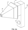
- Figure 4 , 4A and 4B are diagrams illustrating an optical condenser adapter 400 of one embodiment of the present invention such as optical condenser adapter 115 for use with reconfigurable handset 110.
- Embodiments of optical condenser adapter 400 permit an operator to quickly and easily reconfigure handset 110 for a different treatment procedure by swapping hygienic insert 300 for optical condenser adapter 400, and vise verse.
- Optical condenser adapter 400 functions by condensing the optical power of light received through a relatively large aperture from laser source 210 for emission from a relatively smaller aperture. In doing so, the density of the optical energy provided by system 100 (referred to herein as fluence) is increased.
- optical condenser adapter 400 comprises handset adapter interface 401. Similar to hygienic insert 300, handset adapter interface 401 has a size and shape compatible with insertion into treatment chamber 220 of handset 110 as shown in Figure 4A . In one embodiment, handset adapter interface 401 includes a base 421 and outer wall 420.
- optical condenser adapter 400 comprises at least two optical members.
- a first optical member 435 is located within the base 421 of handset adapter interface 401.
- the first optical member 435 provides an input aperture 410 that receives the parallel beams of laser light from laser source 210 and shifts the path of the optical energy from the laser light towards the center of optical condenser adapter 400. More particularly, the path of the optical energy is shifted by the configuration of first optical member 435 so that the laser light received by first optical member 435 via aperture 410 is concentrated onto a second optical member 430 located at an output aperture 411 of optical condenser adapter 400.
- the second optical member 430 again shifts the path of the optical energy so that the beams of laser light exiting from aperture 411 are once again aligned.
- the internal region 425 of optical condenser adapter 400 between the first optical member 435 and the second optical member 430 is an open volume.
- a cooling element 415 may be provided at output aperture 411 for removing heat absorbed by surface tissues during treatment of deeper tissues.
- cooling element 415 may be a cooling crystal.
- the cooling element 415 and the second optical element 430 are the same.
- first optical member 435 and the second optical member 430 are Fresnel lenses.
- first optical member 435 is a Fresnel lens comprising five crystal regions, each receiving a different subset of parallel laser light from different elements of laser array 211. Each of the five crystal regions has a different Fresnel lens angle to concentrate the optical energy it receives towards the center of optical condenser adapter 400 and second optical member 430.
- second optical member 430 includes a Fresnel lens having crystal regions angled to correspond to angles of each received subset received from first optical member 435.
- optical condenser adapter 400 can be realized to provide the operating physician with different size and shape configurations for output aperture 411.
- output aperture may be round, elliptical, diamond, square, or any other geometric shape or combination of shapes.
- an optical condenser adapter 400 may be tuned for use with specific wavelengths of light emitted from laser source 210, such as through the selection of particular materials for one or both of the first optical member 435 and the second optical member 430.
- the inner surfaces of outer walls 405 that face internal region 425 are coated with reflective material which reduces optical energy loss during light propagation from the first optical element 435 to the second optical element 430.
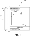
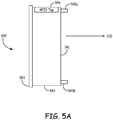
- Figures 5 , 5A and 5B are diagrams illustrating various means for identifying the present configuration of handset 110.
- Figure 5 illustrates one or more alternate embodiments of handset 110 having one or more attachment sensors such as 510a, 510b and 515.
- handset 110 comprises one or more attachment sensors 510a, 510b, which identify what attachment, if any, is inserted into chamber 220.
- attachment sensors 510a, 510b detect the which set of pins (i.e., 545a/545b or 565a/565b) are present and associates the particular pattern of present pins to identify which attachment is inserted into chamber 220.
- differing patterns of pins may be identified, for example, based on pin locations, numbers of pins, pin lengths, or electrical properties. An absence of detected pins may indicate that nothing is inserted.
- handset 110 comprises attachment sensor 515 which includes an RFID reader 515.
- attachment sensor 515 reads attachment data from the RFID tag of the attachment inserted into chamber 220 (i.e., 546 or 566) to identify which attachment is inserted into chamber 220. In one embodiment, an absence of a detected RFID tag may indicate that nothing is inserted.
- the attachment data from the RFID tag 566 can indicate the particular configuration of optical condenser adapter 400, such as the size and/or shape of output aperture 411 and whether that particular adapter is tuned for a particular wavelength.
- system 100 verifies the attachment data from the RFID tag 566 is appropriate for the currently selected treatment parameters. For example, if the attachment data indicates that optical condenser adapter 400 is only to be used for specific wavelength, and laser source 210 is configured to emit a different wavelength, system 100 may provide the operator with a warning and/or prohibit firing of laser source 210.
- RFID reader 515 can further write information onto an RFID tag of an attachment. For example, in one implementation RFID reader 515 writes data onto an RFID tag 546 of an hygienic insert 300 indicating when the hygienic insert 300 has been used. If an operator inadvertently installs a previously used hygienic insert 300, system 100 may provide the operator with a warning and/or prohibit operation of laser source 210. In one embodiment, a unique session ID is written onto RFID tag 546 to permit reuse of a hygienic insert 300 on the same patient during a particular treatment session but otherwise prevent its reuse. Similarly, data may optionally also be written onto RFID tag 566 of optical condenser adapter 400.
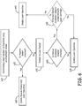
- Figure 6 is a flow chart illustrating a method of one embodiment of the present invention relating to detecting and controlling the operation of laser system 100 based on the detected configuration of handset 110.
- the method starts at 610 with determining a laser handset configuration using an attachment sensor.
- the attachment sensor may determine the configuration using pin configurations and/or RFID tags, such as described above with respect to Figure 5 .
- other detection means may be used.
- the method proceeds to 615 with determining whether a hygienic insert is attached to the laser handset. When a hygienic insert is attached, the method proceeds to 620 with enabling operation of a vacuum channel and laser source.
- the handset is configured for vacuum assisted laser treatments such as described above.
- a hygienic insert such as insert 300
- the handset is configured for vacuum assisted laser treatments such as described above.
- the laser handset is placed onto a region of patient skin tissue, the skin seals against a flange of the hygienic insert.
- a vacuum is applied within a cavity of the insert by a vacuum channel in the handset. The vacuum sucks in at least a portion of the patient skin tissue into the cavity and towards the laser source of the handset.
- the method proceeds to 625 with disabling the vacuum channel of the handset. Disabling the vacuum channel of the handset when no hygienic insert is detected prevents inadvertent non-hygienic use of the handset for vacuum assisted laser treatments. If no hygienic insert is detected because an optical condenser adapter is instead installed, then operation of the vacuum channel is unnecessary and may be disabled to prevent wear.
- the method next proceeds to 630 with determining whether an optical condenser adapter is attached to the laser handset. In the case where no optical condenser adapter is detected, and no hygienic insert is detected, then the laser handset may not be properly set up for use and the method proceeds to 635 with disabling laser operation. In one embodiment, when it is determine that an optical condenser adapter is attached, the method proceeds to 645 with enabling laser operation. In one embodiment, the method optionally proceeds to 640 with determining whether the attached optical condenser adapter is compatible with the present laser settings. If not, the method proceeds to 635 with disabling laser operation. When the adapter and present laser setting are compatible, the method proceeds to 645 with enabling laser operation.
- Figure 7 is a block diagram illustrating at 700 one embodiment of a configuration of system 100 for implementing the method described in Figure 6 .
- Handset 110 comprises laser source 210, vacuum channel 224, a vacuum sensor 724, an attachment sensor 726 (such as attachment sensors 510a,b and 515, for example) and trigger sensor 728.
- base unit 120 comprises power supply 122, vacuum source 126 and logic 126.
- Power supply 122 provides the electrical energy for operating laser source 210.
- Vacuum source 740 provides the negative pressure for operating vacuum channel 224.
- logic 126 comprises one or more interlocks (712, 714, 716) for controlling operation of laser source 210 and vacuum channel 224 based on inputs received from vacuum sensor 724, attachment sensor 726, and trigger sensor 728.
- attachment sensor interlock logic 714 receives inputs representing the state of attachment sensor 726. When a hygienic insert 300 is detected by attachment sensor 726, attachment sensor interlock logic 714 enables operation of vacuum channel 224. Otherwise, when an optical condenser attachment is detected, operation of vacuum channel 224 is disabled by attachment sensor interlock logic 714. In alternate embodiments, enabling or disabling of vacuum channel 224 may be achieved, for example, by altering a valve alignment between vacuum source 124 and vacuum channel 224 or by electrically controlling vacuum source 740. Attachment sensor interlock logic 714 may disable operation of both vacuum channel 224 and laser source 210 when no attachment is detected. Similarly, attachment sensor interlock logic 714 may disable operation of both of vacuum channel 224 and laser source 210 when it detects an incompatibility between the attachment and the present laser settings or other system parameters.
- Trigger sensor interlock logic 716 receives inputs representing the state of trigger sensor 728. In one embodiment, when trigger sensor 728 is depressed, that indicates to logic 710 that the operator wants to activate the laser source 210.
- Vacuum sensor 724 monitors vacuum within cavity 320 and is coupled to vacuum sensor interlock logic 712. In one embodiment, as long as vacuum sensor interlock logic 712 determines that the vacuum within cavity 320 is insufficient (i.e., not meeting a predetermined pressure threshold), it blocks operation of laser source 210. When vacuum sensor interlock logic 712 determine that there is a sufficient vacuum within cavity 320, it proceeds with firing of laser source 210.
- attachment sensor interlock logic 714 Assuming that an optical condenser adapter 400 is attached, laser operation should not be disabled by attachment sensor interlock logic 714, while vacuum operation will be disabled by attachment sensor interlock logic 714. In that case, vacuum sensor interlock logic 712 is bypassed and trigger sensor interlock logic 716 will activate laser source 210 directly based on the state of trigger sensor 720.
- FIGS. 8 , 8A , 9 , 9A and 10 are diagrams illustrating alternate cooling mechanism embodiments for optical condenser adapter 400.
- optical condenser adapter 400 comprises a cooling element 415 at output aperture 411 which functions to cool upper layers of skin while the optical energy emitted by output aperture 411 treats tissues located at lower layers beneath the skin's surface. In order to perform this function, heat absorbed by cooling element 415 must be removed so that cooling element 415 continues to have a sufficient heat absorbing capacity.
- handset 110 further comprises a coolant delivery channel 810 and a coolant return channel 820.
- optical condenser adapter 400 further comprises a coolant delivery channel 815, a heat exchanging interface 830 interfacing with cooling element 830, and a coolant return channel 825.
- channels 810 and 820 are coupled to respective channels 815 and 825 to form a complete circulating coolant circuit.
- pre-cooled circulating liquid coolant is provided by handset 110 by channel 810 to heat exchanging interface 830 via channel 815.
- the pre-cooled circulating liquid coolant absorbs the thermal energy accumulating in cooling element 415 and removes that heat through channels 825 and 820.
- FIG. 8A An alternate but similar embodiment is illustrated in Figure 8A .
- coolant delivery channel 850 and coolant return channel 855 in optical condenser adapter 400 are coupled via an umbilical connection 860 to base unit 120.
- pre-cooled circulating liquid coolant is provided to coolant delivery channel 850 by umbilical connection 860.
- the pre-cooled circulating liquid coolant absorbs the thermal energy accumulating in cooling element 415 and removes that heat through coolant return channel 855 back through umbilical connection 860 to base unit 120.
- thermoelectric cooling device 910 coupled to crystal 415.
- handset 110 further comprises cooler power conductors 920.
- a corresponding set of cooler power conductors 925 are integrated into optical condenser adapter 400. Cooler power conductors 925 in turn are electrically coupled to thermoelectric cooling device 910. With optical condenser adapter 400 coupled to handset 110, cooler power conductors 920 are coupled to respective Cooler power conductors 925 to form an electrical circuit powering thermoelectric cooling device 910.
- electrical power is provided by handset 110 to thermoelectric cooling device 910 which absorbs the thermal energy accumulating in cooling element 415 and dissipates the heat away from cooling element 415.
- An alternate embodiment is illustrated in Figure 9A . Instead of having electric power for thermoelectric cooling device 910 delivered by handset 110, Cooler power conductors 915 in optical condenser adapter 400 instead receive electrical power from base unit 120 via an umbilical connection 940 to base unit 120.
- thermal pipes 1010 integrated into optical condenser adapter 400.
- thermal pipes 1010 absorb the thermal energy accumulating in cooling element 415 and dissipates the heat away from cooling element 415.
- FIG 11 is a diagram of a laser treatment system 1100 of another embodiment of the present invention.
- Laser treatment system 1100 includes a reconfigurable handset 1110 coupled to a base unit 1120 by a cable 1112.
- system 1100 further includes at least one an optical condenser adapter 1115 which operates as an attachment to handset 1110.
- optical condenser adapter 1115 in an adapter such as adapter 115 or adapter 400 described above.
- the present disclosure further described additional embodiments where an optical condenser adapter 1115 is used in conjunction with a reconfigurable handset 1110 that may not need to function as a large-area low-fluence instrument when an optical condenser adapter 1115 is not utilized. That is, it is contemplated that for at least some embodiment, reconfigurable handset 1110 is always used in conjunction with at least one of a plurality of alternate optical condenser adapters.
- the handset 1110 When one of a plurality of available optical condenser adapters 1115 is coupled to handset 1110, the handset 1110 is configured to function as a small-area high-fluence instrument. Such applications may generally be considered contact applications because an optical element of the optical condenser adapter 1115 is typically placed in contact with a treatment area. For this reason, cooling elements may be incorporated into optical condenser adapter 1115 as discussed above with respect to optical condenser adapter 400.
- the base unit 1120 comprises at least one power supply 1122 and logic 1126 that support the treatment functions provided by reconfigurable handset 1110 as described herein.
- FIG. 12 is a diagram illustrating one embodiment of reconfigurable handset 1110.
- Optical energy is generated by handset 1110 using a laser source 1210, which in one embodiment comprises a laser array 1211.
- An adapter chamber 1220 is positioned within handset 1110, which defines a space to which optical energy from laser source 1210 is provided.
- Adapter chamber 1220 includes an adapter aperture 1222.
- adapter aperture 1222 provides an interface that accepts optical condenser adapter 1115, as described below.
- Activation of the laser source 1210 is initiated by a trigger 1226.
- Embodiments of system 1100 permit an operator to quickly and easily reconfigure handset 110 for a different treatment procedures by swapping out one optical condenser adapter 1115 for another.
- the optical condenser 400 described above may also function as optical condenser adapter 1115.
- optional configurations discussed above with respect to utilizing optical condenser 400 with reconfigurable handset 110 would also apply to utilizing optical condenser 400 with reconfigurable handset 1110.
- the first optical member of optical condenser 400 may receive parallel laser light from laser array 1211 in the same way as it would from laser array 211 described above.
- optical condenser adapter 400's handset adapter interface 401 has a size and shape compatible with insertion into adapter chamber 1220 of handset 1110 as shown in Figure 13A .
- multiple and different implementations of optical condenser adapter 400 can be realized to provide the operating physician with different size and shape configurations for output aperture 411.
- output aperture 411 may be round, elliptical, diamond, square, or any other geometric shape or combination of shapes.
- the delivered fluence can be selected by selecting an optical condenser adapter 400 having an appropriate output aperture 411 size. That is, a smaller output aperture 411 concentrates optical energy generated by laser source 1210 onto a smaller area, thus providing a higher delivered fluence to that area than a larger output aperture 411 would.
- an optical condenser adapter 400 may be tuned for use with specific wavelengths of light emitted from laser source 1210, such as through the selection of particular materials for one or both of the first optical member 435 and the second optical member 430.
- the inner surfaces of outer walls 405 that face internal region 425 are coated with reflective material which reduces optical energy loss during light propagation from the first optical element 435 to the second optical element 430.
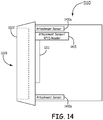
- Figure 14 is a diagram illustrating various means for identifying the present configuration of handset 1110.
- Figure 14 illustrates one or more alternate embodiments of handset 1110 having one or more attachment sensors such as 1410a, 1410b and 1415.
- Handset 1110 comprises one or more attachment sensors 1410a, 1410b, which identify what attachment, if any, is inserted into chamber 1220.
- one implementation of optical condenser adapter 400 (shown previously in Figure 5B ) optionally further comprises one or both of pins 565a and 565b.
- attachment sensors 1410a, 1410b detect the which set of pins (i.e., 545a/545b or 565a/565b) are present and associates the particular pattern of present pins to identify which attachment is inserted into chamber 1220.
- differing patterns of pins may be identified, for example, based on pin locations, numbers of pins, pin lengths, or electrical properties. An absence of detected pins may indicate that nothing is inserted.
- handset 1110 comprises attachment sensor 1415 which includes an RFID reader 1415.
- attachment sensor 1415 reads attachment data from the RFID tag of the attachment inserted into chamber 1220 (i.e., 546 or 566) to identify which attachment is inserted into chamber 1220. In one embodiment, an absence of a detected RFID tag may indicate that nothing is inserted.
- the attachment data from the RFID tag 566 can indicate the particular configuration of optical condenser adapter 400, such as the size and/or shape of output aperture 411 and whether that particular adapter is tuned for a particular wavelength.
- system 1100 verifies the attachment data from the RFID tag 566 is appropriate for the currently selected treatment parameters. For example, if the attachment data indicates that optical condenser adapter 400 is only to be used for specific wavelength, and laser source 1210 is configured to emit a different wavelength, system 1100 may provide the operator with a warning and/or prohibit firing of laser source 1210.
- RFID reader 1415 can further write information onto an RFID tag of an attachment.
- RFID reader 515 writes data onto an RFID tag 566 indicating when optical condenser adapter 400 has been used.
- a unique session ID is written onto RFID tag 556 to permit reuse of a optical condenser adapter 400 on the same patient during a particular treatment session but otherwise prevent its reuse.
- other data may optionally also be written onto RFID tag 566 of optical condenser adapter 400.
- attachment sensors such as 1410a, 1410b and 1415 may function to detect when an incompatible attachment is installed into the treatment chamber 1220. For example, in one embodiment, if a hygienic insert 330 is mistakenly installed onto attachment 1110, system 1100 may provide the operator with a warning and/or prohibit firing of laser source 1210 based on either not recognizing the attachment identified by the attachment sensors 1410a, 1410b and 1415, or by affirmatively recognizing the identified attachment as an incompatible attachment.
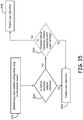
- Figure 15 is a flow chart illustrating a method of the present invention relating to detecting and controlling the operation of laser system 1100 based on the detected configuration of handset 1110.
- the method starts at 1510 with determining a laser handset configuration using an attachment sensor.
- the attachment sensor may determine the configuration using pin configurations and/or RFID tags, such as described above with respect to Figure 14 .
- other detection means may be used.
- the method proceeds to 1530 with determining whether an optical condenser adapter is attached to the laser handset. In the case where no optical condenser adapter is detected, then the laser handset may not be properly set up for use and the method proceeds to 1535 with disabling laser operation.
- the method when it is determine that an optical condenser adapter is attached, the method proceeds to 1545 with enabling laser operation. In one embodiment, the method optionally proceeds to 1540 with determining whether the attached optical condenser adapter is compatible with the present laser settings. If not, the method proceeds to 1535 with disabling laser operation. When the adapter and present laser setting are compatible, the method proceeds to 1545 with enabling laser operation.
- Figure 16 is a block diagram illustrating at 1600 one embodiment of a configuration of system 1100 for implementing the method described in Figure 15 .
- Handset 1110 comprises laser source 1210, an attachment sensor 1626 (such as attachment sensors 1410a,b and 1415, for example) and trigger sensor 1628.
- base unit 1120 comprises power supply 1122 and logic 1126.
- Power supply 1122 provides the electrical energy for operating laser source 1210.
- logic 126 comprises one or more interlocks (1614, 1616) for controlling operation of laser source 1210 based on inputs received from attachment sensor 1626, and trigger sensor 1628.
- attachment sensor interlock logic 1614 receives inputs representing the state of attachment sensor 1626. When an optical condenser attachment is correctly inserted, that action is detected by attachment sensor 1626 and communicated to attachment sensor interlock logic 1614. Attachment sensor interlock logic 1614 may disable operation of laser source 1210 when either no attachment is detected, or when an incompatible or unauthorized attachment is detected. Similarly, attachment sensor interlock logic 1614 may disable operation of laser source 1210 when it detects an incompatibility between the attachment and the present laser settings or other system parameters.
- either logic 1126 or logic 126 may be updated (e.g. by a firmware or software upgrade) to recognize newly authorized attachments, or disable previously authorized attachments. For example, if a previously authorized attachment has been recalled or for whatever reason is no longer supported for used on a particular system, logic 126 and/or logic 1126 may be updated to disable operation of the respective laser source 210 and/or 1210 (that is, de-authorize the attachment) when attachment of that previously authorized attachment is identified. Further, in some embodiments, when logic 1126 or logic 126 is updated to disable a previously authorized attachment, when that previously authorized attachment is installed, the logic may update, for example, relevant information on the RFID tag of the attachment itself. For example, the RFID tag of a recalled or otherwise no-longer-supported attachment can be updated by one system to prevent the use of that attachment on any other system.
- Trigger sensor interlock logic 1616 receives inputs representing the state of trigger sensor 1628. In one embodiment, when trigger sensor 1628 is depressed, that indicates to logic 1610 that the operator wants to activate the laser source 1210. Assuming that an appropriate optical condenser adapter 400 is attached, laser operation should not be disabled by attachment sensor interlock logic 1614. In that case trigger sensor interlock logic 1616 will activate laser source 1210 based on the state of trigger sensor 1620.
- each of the disclosures of Figure 8 , 8A , 9 , 9A and 10 illustrating alternate cooling mechanism embodiments for optical condenser adapter 400 are applicable and may be used in conjunction with handset 1110 as well as handset 110.
Landscapes
- Health & Medical Sciences (AREA)
- Life Sciences & Earth Sciences (AREA)
- Physics & Mathematics (AREA)
- Surgery (AREA)
- Engineering & Computer Science (AREA)
- Biomedical Technology (AREA)
- Animal Behavior & Ethology (AREA)
- Veterinary Medicine (AREA)
- Nuclear Medicine, Radiotherapy & Molecular Imaging (AREA)
- Public Health (AREA)
- General Health & Medical Sciences (AREA)
- Optics & Photonics (AREA)
- Heart & Thoracic Surgery (AREA)
- Molecular Biology (AREA)
- Medical Informatics (AREA)
- Electromagnetism (AREA)
- Otolaryngology (AREA)
- Pathology (AREA)
- Oral & Maxillofacial Surgery (AREA)
- Radiology & Medical Imaging (AREA)
- Biophysics (AREA)
- Radiation-Therapy Devices (AREA)
- Laser Surgery Devices (AREA)
Claims (14)
- Procédé pour faire fonctionner un appareil de traitement laser reconfigurable qui a un combiné (110) qui comprend une chambre de traitement (220) et une source laser (210) arrangée pour projeter de l'énergie optique dans la chambre de traitement (220), le procédé comprenant : la détermination de la configuration d'un combiné laser qui utilise un détecteur de fixation (510a, 510b, 515) ; lors de la détermination de la configuration du combiné laser, la détermination qu'une première fixation (115) reliée à la chambre de traitement (220) du combiné laser (110) est une fixation agréée (115) permettant le fonctionnement de la source laser (210) ; lors de la détermination de la configuration du combiné laser, la détermination qu'une fixation agréée (115) n'est pas reliée à la chambre de traitement (220) du combiné laser (110), désactivation du fonctionnement de la source laser (210) et lors de la détermination qu'une fixation (115) n'est pas compatible avec des paramètres de traitement actuellement sélectionnés (640) sur la base d'informations du détecteur de fixation (510a, 510b, 515), blocage de l'activation de l'arrangement laser (211).
- Procédé selon la revendication 1 comprenant de plus : lorsque la détermination de la configuration du combiné laser détermine qu'aucune fixation (115) n'est reliée à la chambre de traitement (220) du combiné laser (110), désactivation du fonctionnement de la source laser (210).
- Procédé selon l'une quelconque des revendications 1 à 2, la première fixation (115) comprenant une étiquette RFID inscriptible, le procédé comprenant de plus : l'écriture de données sur l'étiquette RFID (566).
- Système de traitement laser portatif reconfigurable (100), le système comprenant : une unité de base (120), un combiné (110) qui comprend une chambre de traitement (220) qui a une ouverture de traitement (222) et une source laser (210) arrangée pour projeter de l'énergie optique dans la chambre de traitement (220), le combiné (110) étant couplé à l'unité de base (120), une fixation (115) ayant une interface d'adaptateur (401) avec des dimensions compatibles avec la connexion à la chambre de traitement, un détecteur de déclenchement (728) sur le combiné, le détecteur de déclenchement étant couplé à un circuit logique (126) adapté pour commander l'activation de l'arrangement laser (211), un détecteur de fixation (510a, 510b, 515) dans le combiné arrangé pour détecter la connexion de l'interface adaptée avec la chambre de traitement (220) à travers l'ouverture de traitement (222), le détecteur de fixation (510a, 510b, 515) étant couplé au circuit logique (126), le circuit logique étant adapté pour permettre l'activation de l'arrangement laser (211) lorsque le détecteur de fixation détecte une fixation agréée reliée à l'ouverture de traitement (222), le circuit logique étant adapté pour désactiver l'activation de l'arrangement laser (211) lorsque le détecteur de fixation ne réussit pas à détecter une fixation agréée (115) reliée à l'ouverture de traitement (222), le système étant caractérisé en ce que le circuit logique (126) est de plus adapté pour déterminer si la fixation (115) est compatible avec des paramètres de traitement actuellement sélectionnés (640) sur la base d'informations du détecteur de fixation (510a, 510b, 515) et le circuit logique (126) étant adapté pour bloquer l'activation de l'arrangement laser (211) s'il détermine que la fixation (115) n'est pas compatible avec des paramètres de traitement actuellement sélectionnés (640).
- Système selon la revendication 4, la fixation (115) comprenant un adaptateur de condenseur optique (400) comprenant : une interface d'adaptateur (401) compatible avec le connexion à la chambre de traitement (220) du combiné (110), l'interface d'adaptateur (401) comprenant une ouverture d'entrée (410), un premier élément optique (435) positionné à l'ouverture d'entrée, un second élément optique (439) à une ouverture de sortie de l'adaptateur de condenseur optique (400), le premier élément optique (435) étant arrangé pour recevoir des faisceaux parallèles de lumière laser générés par l'arrangement laser (211) et pour décaler les faisceaux de lumière laser à concentrer au second élément optique (430).
- Système selon la revendication 5, le second élément optique (430) étant arrangé pour décaler davantage les faisceaux de lumière laser reçus par le premier élément optique (435) pour produire des faisceaux sensiblement parallèles de lumière laser provenant de l'ouverture de sortie (411).
- Système selon la revendication 5 ou 6, l'un ou les deux éléments optiques, le premier élément optique (435) et le second élément optique (430) étant des éléments lentilles de Fresnel.
- Système selon l'une quelconque des revendications 5 à 7, l'ouverture de sortie (411) étant formée comme un polygone, un cercle ou une ellipse ou une combinaison de ceux-ci.
- Système selon l'une quelconque des revendications 5 à 8, l'adaptateur de condenseur optique (400) comprenant de plus un élément de refroidissement (415) à l'ouverture de sortie (411).
- Système selon l'une quelconque des revendications 4 à 9, au moins une partie du circuit logique (126) étant une partie intégrante soit du combiné (510a, 510b, 515), soit de l'unité de base (120).
- Système selon l'une quelconque des revendications 4 à 10, le détecteur de fixation (510a, 510b, 515) étant adapté pour lire différents configurations de pointes de la fixation (115).
- Système selon l'une quelconque des revendications 4 à 11, la fixation comprenant une étiquette RFID qui peut être lue par le détecteur de fixation (515) et le détecteur de fixation (515) étant adapté pour écrire des données dans une ou plusieurs étiquettes RFID (566).
- Système selon la revendication 11 ou 12, le circuit logique (126) étant adapté pour générer un avertissement pour l'opérateur lorsqu'il détermine que la fixation installée (115) n'est pas compatible avec des paramètres de traitement actuellement sélectionnés (640).
- Système selon l'une quelconque des revendications 4 à 13, le circuit logique (126) pouvant être mis à jour pour reconnaître des fixations nouvellement agréées (115) et pour désactiver des fixations précédemment agréées.
Applications Claiming Priority (3)
| Application Number | Priority Date | Filing Date | Title |
|---|---|---|---|
| US13/363,570 US9078681B2 (en) | 2012-02-01 | 2012-02-01 | Reconfigurable handheld laser treatment systems and methods |
| US13/413,826 US9149332B2 (en) | 2012-02-01 | 2012-03-07 | Reconfigurable handheld laser treatment systems and methods |
| PCT/IB2013/050779 WO2013114290A1 (fr) | 2012-02-01 | 2013-01-30 | Systèmes de traitement laser portatifs, reconfigurables, et procédés |
Publications (2)
| Publication Number | Publication Date |
|---|---|
| EP2809397A1 EP2809397A1 (fr) | 2014-12-10 |
| EP2809397B1 true EP2809397B1 (fr) | 2017-07-12 |
Family
ID=48143607
Family Applications (1)
| Application Number | Title | Priority Date | Filing Date |
|---|---|---|---|
| EP13717977.6A Active EP2809397B1 (fr) | 2012-02-01 | 2013-01-30 | Systèmes de traitement laser portatifs, reconfigurables, et procédés |
Country Status (4)
| Country | Link |
|---|---|
| US (3) | US9149332B2 (fr) |
| EP (1) | EP2809397B1 (fr) |
| IL (2) | IL233912B (fr) |
| WO (1) | WO2013114290A1 (fr) |
Families Citing this family (20)
| Publication number | Priority date | Publication date | Assignee | Title |
|---|---|---|---|---|
| US10561464B2 (en) * | 2013-10-08 | 2020-02-18 | Lumenis Ltd. | Laser treatment system and cooling device |
| WO2017019836A1 (fr) | 2015-07-28 | 2017-02-02 | Photonmd, Llc | Systèmes et procédés pour la modulation photothérapeutique d'oxyde nitrique |
| US12109429B2 (en) | 2015-07-28 | 2024-10-08 | Know Bio, Llc | Phototherapeutic light for treatment of pathogens |
| US11400308B2 (en) | 2017-11-21 | 2022-08-02 | Cutera, Inc. | Dermatological picosecond laser treatment systems and methods using optical parametric oscillator |
| EP3610818A1 (fr) * | 2018-08-13 | 2020-02-19 | Koninklijke Philips N.V. | Dispositif portable permettant d'effectuer une opération de traitement |
| DK180064B1 (en) * | 2018-08-30 | 2020-03-03 | Energy Laser A/S | A laser probe for low-level laser therapy and a method of controlling such laser probe |
| US11083910B2 (en) * | 2018-09-19 | 2021-08-10 | Lg Electronics Inc. | Pet care device and method for controlling pet care device |
| US11445702B2 (en) | 2018-09-19 | 2022-09-20 | Lg Electronics Inc. | Pet care device |
| JP7355431B2 (ja) * | 2019-08-09 | 2023-10-03 | 深▲せん▼市洋沃電子有限公司 | 携帯式脱毛装置 |
| US10864380B1 (en) | 2020-02-29 | 2020-12-15 | Cutera, Inc. | Systems and methods for controlling therapeutic laser pulse duration |
| US11253720B2 (en) | 2020-02-29 | 2022-02-22 | Cutera, Inc. | Dermatological systems and methods with handpiece for coaxial pulse delivery and temperature sensing |
| US12447354B2 (en) * | 2020-03-19 | 2025-10-21 | Know Bio, Llc | Illumination devices for inducing biological effects |
| US11147984B2 (en) | 2020-03-19 | 2021-10-19 | Know Bio, Llc | Illumination devices for inducing biological effects |
| US11986666B2 (en) | 2020-03-19 | 2024-05-21 | Know Bio, Llc | Illumination devices for inducing biological effects |
| US12011611B2 (en) | 2020-03-19 | 2024-06-18 | Know Bio, Llc | Illumination devices for inducing biological effects |
| US12347337B2 (en) | 2020-12-10 | 2025-07-01 | Know Bio, Llc | Enhanced testing and characterization techniques for phototherapeutic light treatments |
| US12115384B2 (en) | 2021-03-15 | 2024-10-15 | Know Bio, Llc | Devices and methods for illuminating tissue to induce biological effects |
| US11654294B2 (en) | 2021-03-15 | 2023-05-23 | Know Bio, Llc | Intranasal illumination devices |
| KR20250106911A (ko) * | 2024-01-04 | 2025-07-11 | 주식회사 루트로닉 | Rf 에너지를 이용한 치료장치, 이의 제어방법 및 이를 이용한 치료방법 |
| JP7674580B1 (ja) * | 2024-10-23 | 2025-05-09 | 東京医研株式会社 | 光線治療器 |
Family Cites Families (44)
| Publication number | Priority date | Publication date | Assignee | Title |
|---|---|---|---|---|
| WO1989000871A1 (fr) | 1987-07-24 | 1989-02-09 | Katona Belane | Appareil permettant le rayonnement par lumiere polarisee |
| US5100417A (en) | 1990-07-13 | 1992-03-31 | American Cyanamid Company | Suture anchor and driver assembly |
| US6110167A (en) * | 1990-10-31 | 2000-08-29 | Premier Laser Systems, Inc. | Contact tip for laser surgery |
| US5344418A (en) * | 1991-12-12 | 1994-09-06 | Shahriar Ghaffari | Optical system for treatment of vascular lesions |
| US6251100B1 (en) | 1993-09-24 | 2001-06-26 | Transmedica International, Inc. | Laser assisted topical anesthetic permeation |
| US5728090A (en) * | 1995-02-09 | 1998-03-17 | Quantum Devices, Inc. | Apparatus for irradiating living cells |
| US7022121B2 (en) | 1999-03-09 | 2006-04-04 | Thermage, Inc. | Handpiece for treatment of tissue |
| US6544193B2 (en) | 1996-09-04 | 2003-04-08 | Marcio Marc Abreu | Noninvasive measurement of chemical substances |
| US6517532B1 (en) | 1997-05-15 | 2003-02-11 | Palomar Medical Technologies, Inc. | Light energy delivery head |
| US7204832B2 (en) | 1996-12-02 | 2007-04-17 | Pálomar Medical Technologies, Inc. | Cooling system for a photo cosmetic device |
| US6310901B1 (en) | 1998-06-03 | 2001-10-30 | Jds Uniphase Corporation | Automated AC filament universal laser power controller in a gas ion laser system and method |
| US7041094B2 (en) | 1999-03-15 | 2006-05-09 | Cutera, Inc. | Tissue treatment device and method |
| US6454763B1 (en) | 1999-08-05 | 2002-09-24 | Paradigm Medical Industries Inc. | Laser surgical handpiece with photon trap |
| USD443059S1 (en) | 1999-09-27 | 2001-05-29 | Kai R & D Center Co., Ltd. | Replaceable blade cartridge for cornea incising devices |
| US6758845B1 (en) | 1999-10-08 | 2004-07-06 | Lumenis Inc. | Automatic firing apparatus and methods for laser skin treatment over large areas |
| KR200225362Y1 (ko) * | 2000-07-07 | 2001-06-01 | 박종윤 | 거리감지 센서를 설치한, 고출력 반도체 레이저 다이오드(high power semiconductor laser diode)를 이용한, 일체형 휴대용 의료용 레이저 치료기구 |
| US7293871B2 (en) * | 2000-11-27 | 2007-11-13 | Ophthonix, Inc. | Apparatus and method of correcting higher-order aberrations of the human eye |
| WO2002052322A1 (fr) | 2000-12-22 | 2002-07-04 | Asah Medico A/S | Ensemble connecteur a fibre optique |
| US6458094B1 (en) | 2001-04-11 | 2002-10-01 | Welch Allyn, Inc. | Disposable tip for body cavity irrigation system |
| USD453829S1 (en) | 2001-04-16 | 2002-02-19 | Welch Allyn, Inc. | Disposable insertion tip for a body cavity irrigation device |
| EP1414361B1 (fr) | 2001-07-27 | 2014-04-30 | Koninklijke Philips N.V. | Dispositif de traitement de la peau comprenant un processeur destine a determiner la dose d'impulsions de rayonnement |
| US8287524B2 (en) | 2001-08-23 | 2012-10-16 | Jerry Siegel | Apparatus and method for performing radiation energy treatments |
| US6942658B1 (en) | 2001-08-24 | 2005-09-13 | Boilase Technology, Inc. | Radiation emitting apparatus with spatially controllable output energy distributions |
| US7384419B2 (en) | 2002-08-26 | 2008-06-10 | Biolase Technology, Inc. | Tapered fused waveguide for delivering treatment electromagnetic radiation toward a target surfaced |
| US20040030325A1 (en) | 2001-12-05 | 2004-02-12 | Nicholas Cahir | Removable attachments for laser emitting devices |
| EP1627662B1 (fr) | 2004-06-10 | 2011-03-02 | Candela Corporation | Appareil pour le traitement de la peau à l'aide d'une source lumineuse assistée par dépression |
| US7232450B2 (en) | 2003-01-17 | 2007-06-19 | Nova-Tech Engineering, Inc. | Apparatus and method for upper and lower beak treatment |
| US7309335B2 (en) * | 2003-12-31 | 2007-12-18 | Palomar Medical Technologies, Inc. | Dermatological treatment with visualization |
| US8571648B2 (en) | 2004-05-07 | 2013-10-29 | Aesthera | Apparatus and method to apply substances to tissue |
| US20070179482A1 (en) | 2004-05-07 | 2007-08-02 | Anderson Robert S | Apparatuses and methods to treat biological external tissue |
| KR101277022B1 (ko) | 2004-08-06 | 2013-06-24 | 파로스 라이프 코오포레이션 | 치료기와 관련 액세서리, 조성물 및 치료방법 |
| US20060095096A1 (en) | 2004-09-09 | 2006-05-04 | Debenedictis Leonard C | Interchangeable tips for medical laser treatments and methods for using same |
| US8337097B2 (en) * | 2004-09-22 | 2012-12-25 | Densen Cao | Modular surgical laser systems |
| JP2006289098A (ja) | 2005-04-12 | 2006-10-26 | Inolase 2002 Ltd | 皮膚の真空援用式光ベース治療用の装置 |
| USD581050S1 (en) | 2006-03-10 | 2008-11-18 | Medical Device Innovations Limited | Surgical instrument tip |
| USD608881S1 (en) | 2006-10-26 | 2010-01-26 | Lumenis Ltd. | Disposable tip |
| US20080119830A1 (en) | 2006-10-31 | 2008-05-22 | Ramstad Paul O | Disposable tip for laser handpiece |
| WO2008131362A2 (fr) * | 2007-04-20 | 2008-10-30 | Doheny Eye Institute | Centre chirurgical personnel |
| JP2010524593A (ja) * | 2007-04-20 | 2010-07-22 | ドヘニー アイ インスティテュート | 独立手術センター |
| WO2012106689A1 (fr) | 2011-02-03 | 2012-08-09 | Tria Beauty, Inc. | Dispositifs et méthodes dermatologiques à base de rayonnements |
| US8728064B2 (en) | 2011-12-12 | 2014-05-20 | Candela Corporation | Devices for the treatment of biological tissue |
| PL2823785T3 (pl) * | 2013-07-10 | 2018-08-31 | Fotona D.O.O. | Ręczne urządzenie laserowe do celów medycznych |
| US10561464B2 (en) * | 2013-10-08 | 2020-02-18 | Lumenis Ltd. | Laser treatment system and cooling device |
| GB201317752D0 (en) * | 2013-10-08 | 2013-11-20 | Lumenis Ltd | Laser treatment apparatus |
-
2012
- 2012-03-07 US US13/413,826 patent/US9149332B2/en active Active
-
2013
- 2013-01-30 EP EP13717977.6A patent/EP2809397B1/fr active Active
- 2013-01-30 WO PCT/IB2013/050779 patent/WO2013114290A1/fr not_active Ceased
-
2014
- 2014-07-31 IL IL233912A patent/IL233912B/en active IP Right Grant
-
2015
- 2015-06-11 US US14/736,300 patent/US9526578B2/en active Active
-
2016
- 2016-11-16 US US15/352,634 patent/US10653483B2/en active Active
-
2018
- 2018-06-04 IL IL259812A patent/IL259812B/en active IP Right Grant
Also Published As
| Publication number | Publication date |
|---|---|
| US10653483B2 (en) | 2020-05-19 |
| IL259812B (en) | 2020-05-31 |
| IL233912B (en) | 2018-06-28 |
| US20130197495A1 (en) | 2013-08-01 |
| US20150272675A1 (en) | 2015-10-01 |
| WO2013114290A1 (fr) | 2013-08-08 |
| US9149332B2 (en) | 2015-10-06 |
| IL233912A0 (en) | 2014-09-30 |
| US20170056110A1 (en) | 2017-03-02 |
| IL259812A (en) | 2018-07-31 |
| EP2809397A1 (fr) | 2014-12-10 |
| US9526578B2 (en) | 2016-12-27 |
Similar Documents
| Publication | Publication Date | Title |
|---|---|---|
| EP2809397B1 (fr) | Systèmes de traitement laser portatifs, reconfigurables, et procédés | |
| US9078681B2 (en) | Reconfigurable handheld laser treatment systems and methods | |
| EP3478205B1 (fr) | Système laser ophtalmique portatif avec embouts de contact remplaçables et guide de traitement | |
| US12193736B2 (en) | Apparatus and methods for resecting and/or ablating an undesired tissue | |
| AU2006232987B2 (en) | System and method for laser lipolysis | |
| ES2749622T3 (es) | Sistemas de terapia térmica | |
| EP3536240A1 (fr) | Dispositif de lance laser | |
| US10646273B2 (en) | Apparatus for irradiating laser | |
| JP2008529746A (ja) | 皮膚科学的治療装置 | |
| KR20130084316A (ko) | 고강도 선행 서브펄스를 갖는 의료용 레이저에서의 램핑-업 펄스 파워를 위한 개시 시퀀스 | |
| US20100049183A1 (en) | Skull cutting device | |
| EP2320823A2 (fr) | Ablation sans risque | |
| EP4192337A1 (fr) | Planification d'ablation de tumeur par cartographie optique interstitielle | |
| WO2020105096A1 (fr) | Capuchon d'endoscope et système d'endoscope | |
| CN204446106U (zh) | 光纤自动识别的钬激光治疗仪 | |
| US9526579B2 (en) | Combination diffused and focused fiber optic for diagnosis and treatment of diseased cells | |
| Rico et al. | Is the direct in-scope suction (DISS) the solution for the non-prestenting and sheathless flexible ureteroscopy? | |
| US20250001201A1 (en) | Light irradiation device and control method for light irradiation device | |
| Sagnak | Laser Therapy: a Seminal Perspective in Modern Medical Technology: Modern diode lasers enable more gentle medical procedures | |
| WO2025168752A1 (fr) | Dispositif de thermoablation | |
| KR20240026716A (ko) | 초음파 핸드피스 | |
| WO2019130465A1 (fr) | Dispositif de traitement chirurgical |
Legal Events
| Date | Code | Title | Description |
|---|---|---|---|
| PUAI | Public reference made under article 153(3) epc to a published international application that has entered the european phase |
Free format text: ORIGINAL CODE: 0009012 |
|
| 17P | Request for examination filed |
Effective date: 20140821 |
|
| AK | Designated contracting states |
Kind code of ref document: A1 Designated state(s): AL AT BE BG CH CY CZ DE DK EE ES FI FR GB GR HR HU IE IS IT LI LT LU LV MC MK MT NL NO PL PT RO RS SE SI SK SM TR |
|
| AX | Request for extension of the european patent |
Extension state: BA ME |
|
| DAX | Request for extension of the european patent (deleted) | ||
| 17Q | First examination report despatched |
Effective date: 20160311 |
|
| REG | Reference to a national code |
Ref country code: DE Ref legal event code: R079 Ref document number: 602013023378 Country of ref document: DE Free format text: PREVIOUS MAIN CLASS: A61N0005067000 Ipc: A61B0090980000 |
|
| RIC1 | Information provided on ipc code assigned before grant |
Ipc: A61B 18/20 20060101ALI20161128BHEP Ipc: A61B 18/00 20060101ALI20161128BHEP Ipc: A61B 90/98 20160101AFI20161128BHEP Ipc: A61N 5/06 20060101ALI20161128BHEP Ipc: A61N 5/067 20060101ALI20161128BHEP |
|
| GRAP | Despatch of communication of intention to grant a patent |
Free format text: ORIGINAL CODE: EPIDOSNIGR1 |
|
| INTG | Intention to grant announced |
Effective date: 20170126 |
|
| GRAS | Grant fee paid |
Free format text: ORIGINAL CODE: EPIDOSNIGR3 |
|
| GRAA | (expected) grant |
Free format text: ORIGINAL CODE: 0009210 |
|
| AK | Designated contracting states |
Kind code of ref document: B1 Designated state(s): AL AT BE BG CH CY CZ DE DK EE ES FI FR GB GR HR HU IE IS IT LI LT LU LV MC MK MT NL NO PL PT RO RS SE SI SK SM TR |
|
| REG | Reference to a national code |
Ref country code: GB Ref legal event code: FG4D |
|
| REG | Reference to a national code |
Ref country code: CH Ref legal event code: EP |
|
| REG | Reference to a national code |
Ref country code: AT Ref legal event code: REF Ref document number: 907608 Country of ref document: AT Kind code of ref document: T Effective date: 20170715 |
|
| REG | Reference to a national code |
Ref country code: IE Ref legal event code: FG4D |
|
| REG | Reference to a national code |
Ref country code: DE Ref legal event code: R096 Ref document number: 602013023378 Country of ref document: DE |
|
| REG | Reference to a national code |
Ref country code: NL Ref legal event code: MP Effective date: 20170712 |
|
| REG | Reference to a national code |
Ref country code: LT Ref legal event code: MG4D |
|
| REG | Reference to a national code |
Ref country code: AT Ref legal event code: MK05 Ref document number: 907608 Country of ref document: AT Kind code of ref document: T Effective date: 20170712 |
|
| REG | Reference to a national code |
Ref country code: FR Ref legal event code: PLFP Year of fee payment: 6 |
|
| PG25 | Lapsed in a contracting state [announced via postgrant information from national office to epo] |
Ref country code: NO Free format text: LAPSE BECAUSE OF FAILURE TO SUBMIT A TRANSLATION OF THE DESCRIPTION OR TO PAY THE FEE WITHIN THE PRESCRIBED TIME-LIMIT Effective date: 20171012 Ref country code: AT Free format text: LAPSE BECAUSE OF FAILURE TO SUBMIT A TRANSLATION OF THE DESCRIPTION OR TO PAY THE FEE WITHIN THE PRESCRIBED TIME-LIMIT Effective date: 20170712 Ref country code: LT Free format text: LAPSE BECAUSE OF FAILURE TO SUBMIT A TRANSLATION OF THE DESCRIPTION OR TO PAY THE FEE WITHIN THE PRESCRIBED TIME-LIMIT Effective date: 20170712 Ref country code: SE Free format text: LAPSE BECAUSE OF FAILURE TO SUBMIT A TRANSLATION OF THE DESCRIPTION OR TO PAY THE FEE WITHIN THE PRESCRIBED TIME-LIMIT Effective date: 20170712 Ref country code: HR Free format text: LAPSE BECAUSE OF FAILURE TO SUBMIT A TRANSLATION OF THE DESCRIPTION OR TO PAY THE FEE WITHIN THE PRESCRIBED TIME-LIMIT Effective date: 20170712 Ref country code: FI Free format text: LAPSE BECAUSE OF FAILURE TO SUBMIT A TRANSLATION OF THE DESCRIPTION OR TO PAY THE FEE WITHIN THE PRESCRIBED TIME-LIMIT Effective date: 20170712 Ref country code: NL Free format text: LAPSE BECAUSE OF FAILURE TO SUBMIT A TRANSLATION OF THE DESCRIPTION OR TO PAY THE FEE WITHIN THE PRESCRIBED TIME-LIMIT Effective date: 20170712 |
|
| PG25 | Lapsed in a contracting state [announced via postgrant information from national office to epo] |
Ref country code: RS Free format text: LAPSE BECAUSE OF FAILURE TO SUBMIT A TRANSLATION OF THE DESCRIPTION OR TO PAY THE FEE WITHIN THE PRESCRIBED TIME-LIMIT Effective date: 20170712 Ref country code: LV Free format text: LAPSE BECAUSE OF FAILURE TO SUBMIT A TRANSLATION OF THE DESCRIPTION OR TO PAY THE FEE WITHIN THE PRESCRIBED TIME-LIMIT Effective date: 20170712 Ref country code: ES Free format text: LAPSE BECAUSE OF FAILURE TO SUBMIT A TRANSLATION OF THE DESCRIPTION OR TO PAY THE FEE WITHIN THE PRESCRIBED TIME-LIMIT Effective date: 20170712 Ref country code: IS Free format text: LAPSE BECAUSE OF FAILURE TO SUBMIT A TRANSLATION OF THE DESCRIPTION OR TO PAY THE FEE WITHIN THE PRESCRIBED TIME-LIMIT Effective date: 20171112 Ref country code: PL Free format text: LAPSE BECAUSE OF FAILURE TO SUBMIT A TRANSLATION OF THE DESCRIPTION OR TO PAY THE FEE WITHIN THE PRESCRIBED TIME-LIMIT Effective date: 20170712 Ref country code: GR Free format text: LAPSE BECAUSE OF FAILURE TO SUBMIT A TRANSLATION OF THE DESCRIPTION OR TO PAY THE FEE WITHIN THE PRESCRIBED TIME-LIMIT Effective date: 20171013 Ref country code: BG Free format text: LAPSE BECAUSE OF FAILURE TO SUBMIT A TRANSLATION OF THE DESCRIPTION OR TO PAY THE FEE WITHIN THE PRESCRIBED TIME-LIMIT Effective date: 20171012 |
|
| REG | Reference to a national code |
Ref country code: DE Ref legal event code: R097 Ref document number: 602013023378 Country of ref document: DE |
|
| PG25 | Lapsed in a contracting state [announced via postgrant information from national office to epo] |
Ref country code: RO Free format text: LAPSE BECAUSE OF FAILURE TO SUBMIT A TRANSLATION OF THE DESCRIPTION OR TO PAY THE FEE WITHIN THE PRESCRIBED TIME-LIMIT Effective date: 20170712 Ref country code: CZ Free format text: LAPSE BECAUSE OF FAILURE TO SUBMIT A TRANSLATION OF THE DESCRIPTION OR TO PAY THE FEE WITHIN THE PRESCRIBED TIME-LIMIT Effective date: 20170712 Ref country code: DK Free format text: LAPSE BECAUSE OF FAILURE TO SUBMIT A TRANSLATION OF THE DESCRIPTION OR TO PAY THE FEE WITHIN THE PRESCRIBED TIME-LIMIT Effective date: 20170712 |
|
| PLBE | No opposition filed within time limit |
Free format text: ORIGINAL CODE: 0009261 |
|
| STAA | Information on the status of an ep patent application or granted ep patent |
Free format text: STATUS: NO OPPOSITION FILED WITHIN TIME LIMIT |
|
| PG25 | Lapsed in a contracting state [announced via postgrant information from national office to epo] |
Ref country code: IT Free format text: LAPSE BECAUSE OF FAILURE TO SUBMIT A TRANSLATION OF THE DESCRIPTION OR TO PAY THE FEE WITHIN THE PRESCRIBED TIME-LIMIT Effective date: 20170712 Ref country code: SK Free format text: LAPSE BECAUSE OF FAILURE TO SUBMIT A TRANSLATION OF THE DESCRIPTION OR TO PAY THE FEE WITHIN THE PRESCRIBED TIME-LIMIT Effective date: 20170712 Ref country code: EE Free format text: LAPSE BECAUSE OF FAILURE TO SUBMIT A TRANSLATION OF THE DESCRIPTION OR TO PAY THE FEE WITHIN THE PRESCRIBED TIME-LIMIT Effective date: 20170712 Ref country code: SM Free format text: LAPSE BECAUSE OF FAILURE TO SUBMIT A TRANSLATION OF THE DESCRIPTION OR TO PAY THE FEE WITHIN THE PRESCRIBED TIME-LIMIT Effective date: 20170712 |
|
| 26N | No opposition filed |
Effective date: 20180413 |
|
| PG25 | Lapsed in a contracting state [announced via postgrant information from national office to epo] |
Ref country code: SI Free format text: LAPSE BECAUSE OF FAILURE TO SUBMIT A TRANSLATION OF THE DESCRIPTION OR TO PAY THE FEE WITHIN THE PRESCRIBED TIME-LIMIT Effective date: 20170712 |
|
| REG | Reference to a national code |
Ref country code: CH Ref legal event code: PL |
|
| PG25 | Lapsed in a contracting state [announced via postgrant information from national office to epo] |
Ref country code: LU Free format text: LAPSE BECAUSE OF NON-PAYMENT OF DUE FEES Effective date: 20180130 |
|
| REG | Reference to a national code |
Ref country code: IE Ref legal event code: MM4A |
|
| REG | Reference to a national code |
Ref country code: BE Ref legal event code: MM Effective date: 20180131 |
|
| PG25 | Lapsed in a contracting state [announced via postgrant information from national office to epo] |
Ref country code: LI Free format text: LAPSE BECAUSE OF NON-PAYMENT OF DUE FEES Effective date: 20180131 Ref country code: CH Free format text: LAPSE BECAUSE OF NON-PAYMENT OF DUE FEES Effective date: 20180131 Ref country code: BE Free format text: LAPSE BECAUSE OF NON-PAYMENT OF DUE FEES Effective date: 20180131 |
|
| PG25 | Lapsed in a contracting state [announced via postgrant information from national office to epo] |
Ref country code: IE Free format text: LAPSE BECAUSE OF NON-PAYMENT OF DUE FEES Effective date: 20180130 |
|
| PGFP | Annual fee paid to national office [announced via postgrant information from national office to epo] |
Ref country code: FR Payment date: 20190125 Year of fee payment: 7 |
|
| PG25 | Lapsed in a contracting state [announced via postgrant information from national office to epo] |
Ref country code: MC Free format text: LAPSE BECAUSE OF FAILURE TO SUBMIT A TRANSLATION OF THE DESCRIPTION OR TO PAY THE FEE WITHIN THE PRESCRIBED TIME-LIMIT Effective date: 20170712 |
|
| PG25 | Lapsed in a contracting state [announced via postgrant information from national office to epo] |
Ref country code: MT Free format text: LAPSE BECAUSE OF NON-PAYMENT OF DUE FEES Effective date: 20180130 |
|
| PG25 | Lapsed in a contracting state [announced via postgrant information from national office to epo] |
Ref country code: TR Free format text: LAPSE BECAUSE OF FAILURE TO SUBMIT A TRANSLATION OF THE DESCRIPTION OR TO PAY THE FEE WITHIN THE PRESCRIBED TIME-LIMIT Effective date: 20170712 |
|
| PG25 | Lapsed in a contracting state [announced via postgrant information from national office to epo] |
Ref country code: PT Free format text: LAPSE BECAUSE OF FAILURE TO SUBMIT A TRANSLATION OF THE DESCRIPTION OR TO PAY THE FEE WITHIN THE PRESCRIBED TIME-LIMIT Effective date: 20170712 Ref country code: HU Free format text: LAPSE BECAUSE OF FAILURE TO SUBMIT A TRANSLATION OF THE DESCRIPTION OR TO PAY THE FEE WITHIN THE PRESCRIBED TIME-LIMIT; INVALID AB INITIO Effective date: 20130130 |
|
| PG25 | Lapsed in a contracting state [announced via postgrant information from national office to epo] |
Ref country code: CY Free format text: LAPSE BECAUSE OF FAILURE TO SUBMIT A TRANSLATION OF THE DESCRIPTION OR TO PAY THE FEE WITHIN THE PRESCRIBED TIME-LIMIT Effective date: 20170712 Ref country code: MK Free format text: LAPSE BECAUSE OF NON-PAYMENT OF DUE FEES Effective date: 20170712 |
|
| PG25 | Lapsed in a contracting state [announced via postgrant information from national office to epo] |
Ref country code: AL Free format text: LAPSE BECAUSE OF FAILURE TO SUBMIT A TRANSLATION OF THE DESCRIPTION OR TO PAY THE FEE WITHIN THE PRESCRIBED TIME-LIMIT Effective date: 20170712 |
|
| PG25 | Lapsed in a contracting state [announced via postgrant information from national office to epo] |
Ref country code: FR Free format text: LAPSE BECAUSE OF NON-PAYMENT OF DUE FEES Effective date: 20200131 |
|
| REG | Reference to a national code |
Ref country code: GB Ref legal event code: 732E Free format text: REGISTERED BETWEEN 20211104 AND 20211110 |
|
| REG | Reference to a national code |
Ref country code: DE Ref legal event code: R081 Ref document number: 602013023378 Country of ref document: DE Owner name: LUMENIS BE LTD., IL Free format text: FORMER OWNER: LUMENIS LTD., YOKNEAM ILIT, IL |
|
| P01 | Opt-out of the competence of the unified patent court (upc) registered |
Effective date: 20230601 |
|
| REG | Reference to a national code |
Ref country code: DE Ref legal event code: R082 Ref document number: 602013023378 Country of ref document: DE |
|
| PGFP | Annual fee paid to national office [announced via postgrant information from national office to epo] |
Ref country code: DE Payment date: 20250129 Year of fee payment: 13 |
|
| PGFP | Annual fee paid to national office [announced via postgrant information from national office to epo] |
Ref country code: GB Payment date: 20250127 Year of fee payment: 13 |