EP2809100A1 - Apparatuses and method for controlling a discontinuous communication mode - Google Patents
Apparatuses and method for controlling a discontinuous communication mode Download PDFInfo
- Publication number
- EP2809100A1 EP2809100A1 EP20140150104 EP14150104A EP2809100A1 EP 2809100 A1 EP2809100 A1 EP 2809100A1 EP 20140150104 EP20140150104 EP 20140150104 EP 14150104 A EP14150104 A EP 14150104A EP 2809100 A1 EP2809100 A1 EP 2809100A1
- Authority
- EP
- European Patent Office
- Prior art keywords
- radio
- data
- terminal apparatus
- unit
- time information
- Prior art date
- Legal status (The legal status is an assumption and is not a legal conclusion. Google has not performed a legal analysis and makes no representation as to the accuracy of the status listed.)
- Withdrawn
Links
Images


Classifications
-
- H—ELECTRICITY
- H04—ELECTRIC COMMUNICATION TECHNIQUE
- H04W—WIRELESS COMMUNICATION NETWORKS
- H04W24/00—Supervisory, monitoring or testing arrangements
- H04W24/08—Testing, supervising or monitoring using real traffic
-
- H—ELECTRICITY
- H04—ELECTRIC COMMUNICATION TECHNIQUE
- H04W—WIRELESS COMMUNICATION NETWORKS
- H04W52/00—Power management, e.g. TPC [Transmission Power Control], power saving or power classes
- H04W52/02—Power saving arrangements
- H04W52/0209—Power saving arrangements in terminal devices
- H04W52/0212—Power saving arrangements in terminal devices managed by the network, e.g. network or access point is master and terminal is slave
- H04W52/0216—Power saving arrangements in terminal devices managed by the network, e.g. network or access point is master and terminal is slave using a pre-established activity schedule, e.g. traffic indication frame
-
- H—ELECTRICITY
- H04—ELECTRIC COMMUNICATION TECHNIQUE
- H04W—WIRELESS COMMUNICATION NETWORKS
- H04W52/00—Power management, e.g. TPC [Transmission Power Control], power saving or power classes
- H04W52/02—Power saving arrangements
- H04W52/0209—Power saving arrangements in terminal devices
- H04W52/0225—Power saving arrangements in terminal devices using monitoring of external events, e.g. the presence of a signal
- H04W52/0229—Power saving arrangements in terminal devices using monitoring of external events, e.g. the presence of a signal where the received signal is a wanted signal
-
- H—ELECTRICITY
- H04—ELECTRIC COMMUNICATION TECHNIQUE
- H04W—WIRELESS COMMUNICATION NETWORKS
- H04W52/00—Power management, e.g. TPC [Transmission Power Control], power saving or power classes
- H04W52/02—Power saving arrangements
- H04W52/0209—Power saving arrangements in terminal devices
- H04W52/0251—Power saving arrangements in terminal devices using monitoring of local events, e.g. events related to user activity
- H04W52/0258—Power saving arrangements in terminal devices using monitoring of local events, e.g. events related to user activity controlling an operation mode according to history or models of usage information, e.g. activity schedule or time of day
-
- H—ELECTRICITY
- H04—ELECTRIC COMMUNICATION TECHNIQUE
- H04W—WIRELESS COMMUNICATION NETWORKS
- H04W76/00—Connection management
- H04W76/20—Manipulation of established connections
- H04W76/28—Discontinuous transmission [DTX]; Discontinuous reception [DRX]
-
- H—ELECTRICITY
- H04—ELECTRIC COMMUNICATION TECHNIQUE
- H04W—WIRELESS COMMUNICATION NETWORKS
- H04W88/00—Devices specially adapted for wireless communication networks, e.g. terminals, base stations or access point devices
- H04W88/02—Terminal devices
-
- H—ELECTRICITY
- H04—ELECTRIC COMMUNICATION TECHNIQUE
- H04W—WIRELESS COMMUNICATION NETWORKS
- H04W88/00—Devices specially adapted for wireless communication networks, e.g. terminals, base stations or access point devices
- H04W88/08—Access point devices
-
- Y—GENERAL TAGGING OF NEW TECHNOLOGICAL DEVELOPMENTS; GENERAL TAGGING OF CROSS-SECTIONAL TECHNOLOGIES SPANNING OVER SEVERAL SECTIONS OF THE IPC; TECHNICAL SUBJECTS COVERED BY FORMER USPC CROSS-REFERENCE ART COLLECTIONS [XRACs] AND DIGESTS
- Y02—TECHNOLOGIES OR APPLICATIONS FOR MITIGATION OR ADAPTATION AGAINST CLIMATE CHANGE
- Y02D—CLIMATE CHANGE MITIGATION TECHNOLOGIES IN INFORMATION AND COMMUNICATION TECHNOLOGIES [ICT], I.E. INFORMATION AND COMMUNICATION TECHNOLOGIES AIMING AT THE REDUCTION OF THEIR OWN ENERGY USE
- Y02D30/00—Reducing energy consumption in communication networks
- Y02D30/70—Reducing energy consumption in communication networks in wireless communication networks
Definitions
- the embodiments discussed herein are related to a radio terminal apparatus, a communication control apparatus, and a radio communication method.
- a radio terminal apparatus connects to a radio base station and performs data communication via the radio base station.
- a radio communication system is widely used today.
- the timing when the radio terminal apparatus performs data communication is dependent on a user operation. Therefore, there may be a period during which data communication between the radio terminal apparatus and the base station is intensive, and a period during which there is no data communication. For example, when the user accesses to a Web site, data of the Web page is received in bursts. Then, while the user is browsing the Web page, no data is received.
- radio communication system It is costly and inefficient for a radio communication system to have data communication between a radio terminal apparatus and a radio base station available at any time even during the period in which there is no data communication.
- some radio communication systems are designed such that, if there is no data communication for a certain period of time, a radio terminal apparatus may periodically and discontinuously perform transmission and reception.
- CPC Continuous Packet Connectivity
- HSPA High Speed Packet Access
- W-CDMA Wideband Code Division Multiple Access
- a radio network controller (RNC) in a radio access network notifies a radio terminal apparatus of a discontinuous reception (DRX) period and a discontinuous transmission (DTX) period.
- the radio terminal apparatus discontinuously receives control information on a downlink control channel from a radio base station in the notified DRX period. When there is data to be transmitted in the downlink, the presence of data is notified to the radio terminal apparatus at the next DRX timing. Further, the radio terminal apparatus discontinuously transmits control information on an uplink control channel to the radio base station in the notified DTX period. When there is data to be transmitted in the uplink, the presence of data is notified to the radio base station at the next DTX timing.
- a mobile communication system includes a radio base station and a plurality of mobile stations which are operable in three modes: active mode, idle mode, and battery saving mode (see, for example, Japanese Laid-open Patent Publication No. 2005-26991 ).
- This radio base station sets the transmission period of a paging channel to 40 ms if the mobile station is operating in the idle mode, and sets the transmission period of the paging channel to 80 ms if the mobile station is operating in the battery saving mode.
- the mobile station receives the paging channel in the period set by the radio base station.
- a common reception period of 40 ms is set for all the mobile stations that are operating in the idle mode, and a common reception period of 80 ms is set for all the mobile stations that are operating in the battery saving mode.
- the communication period appropriate for a radio terminal apparatus varies depending on the tendency of user operations.
- the present invention is directed to providing a radio terminal apparatus capable of setting an appropriate discontinuous communication period, a communication control apparatus, and a radio communication method.
- a radio terminal apparatus that is operable in a discontinuous communication mode in which at least one of transmission and reception for communicating with a radio base station is performed periodically and discontinuously.
- the radio terminal apparatus includes a measurement unit configured to measure time from when download of data via the radio base station is completed to when download of the next data is requested in response to a user operation, a transmitting unit configured to transmit time information on the time measured by the measurement unit to the radio base station, and a radio control unit configured to acquire, from the radio base station, a parameter indicating at least one of a transmission period and a reception period that is determined on the basis of the time information, and control the discontinuous communication mode.
- FIG. 1 illustrates an example of a radio terminal apparatus 10 according to the first embodiment.
- the radio terminal apparatus 10 is operable in a discontinuous communication mode in which at least one of transmission and reception for communicating with a radio base station 20 is performed periodically and discontinuously. As illustrated in FIG. 1 , the radio terminal apparatus 10 includes a measurement unit 11, a transmitting unit 12, and a radio control unit 13.
- the measurement unit 11 measures time T1 from when download of data via the radio base station 20 is completed (14) to when download of the next data is requested (15) in response to a user operation. For example, if image data is downloaded, the radio terminal apparatus 10 performs decoding, image quality enhancement processing, and the like, on the image data so as to generate display data that may be displayed on a display. The display data is stored in a frame buffer. The measurement unit 11 starts a timer when preparation for displaying the display data is completed and the frame buffer is confirmed to be empty. Then, if a user operation is received, the measurement unit 11 stops the timer.
- the transmitting unit 12 transmits time information on the time T1 measured by the measurement unit 11 to the radio base station 20.
- the radio control unit 13 acquires, from the radio base station 20, a parameter T2 indicating at least one of a transmission period and a reception period that is determined on the basis of the time information, and controls the discontinuous communication mode.
- the parameter T2 is transmitted from the radio base station 20 to the radio terminal apparatus 10 at the time when the discontinuous communication mode is activated.
- the discontinuous communication mode is activated if the amount of packets transmitted by the radio terminal apparatus 10 is less than a threshold or is zero for a predetermined time period, for example.
- the radio terminal apparatus 10 and the radio base station 20 discontinuously perform transmission or reception (16) on the control channel in accordance with the discontinuous communication period indicated by the parameter T2, for example.
- the communication control apparatus 30 controls the radio base station 20.
- the communication control apparatus 30 includes a receiving unit 31 and a control unit 32.
- the receiving unit 31 receives the time information via the radio base station 20.
- the control unit 32 determines the parameter T2 indicating at least one of a transmission period and a reception period on the basis of the time information, and transmits the parameter T2 to the radio terminal apparatus 10 via the radio base station 20.
- FIG. 2 illustrates an example of a radio communication system according to the second embodiment.
- the radio communication system of the second embodiment includes radio terminal apparatuses 100-1 and 100-2, a radio base station 200, a radio network control apparatus 300, and a content server 500.
- the radio network control apparatus 300 and the content server 500 are connected via a core network 400.
- radio terminal apparatuses 100-1 and 100-2 are illustrated.
- the radio communication system may include three or more radio terminal apparatuses.
- only one radio base station 200 is illustrated.
- the radio communication system may include two or more radio base stations.
- the radio base station 200 and the radio network control apparatus 300 are provided separately.
- the radio base station 200 and the radio network control apparatus 300 may be integrated into a single unit.
- the radio terminal apparatuses 100-1 and 100-2 are not distinguished from one another, and are simply referred to as radio terminal apparatuses 100.
- the radio terminal apparatus 100 is an example of a user terminal that is capable of transmitting and receiving data in accordance with a predetermined radio communication protocol.
- Examples of the radio terminal apparatus 100 include user equipment (UE) used in the systems such as W-CDMA, HSPA, Long Term Evolution (LTE), and the like.
- the radio terminal apparatus 100 may be a mobile phone, smartphone, personal computer, tablet computer, or various other types of apparatuses, for example.
- the radio base station 200 performs processing on the physical layer, such as frequency conversion from baseband signals to radio frequency (RF) signals, error correction coding and decoding, modulation and demodulation, and the like.
- the radio base station 200 also performs processing such as spread spectrum, and the like.
- W-CDMA defines a logical node called a Node B that performs processing on the physical layer, such as those described above.
- a base transceiver station (BTS) implemented as a Node B in the W-CDMA system is an example of the radio base station 200.
- radio channels between the radio terminal apparatus 100 and the radio base station 200 such as Dedicated Physical Control Channel (DPCCH), Enhanced Dedicated Channel (E-DCH), High-Speed DPCCH (HS-DPCCH), High-Speed Shared Control Channel (HS-SCCH), E-DCH Absolute Grant Channel (E-AGCH), E-DCH Relative Grant Channel (E-RGCH), E-DCH Dedicated Physical Control Channel (E-DPCCH), E-DCH Dedicated Physical Data Channel (E-DPDCH), Fractional Dedicated Physical Channel (F-DPCH), High-Speed Physical Downlink Shared Channel (HS-PDSCH), Primary Common Control Physical Channel (P-CCPCH), and the like.
- DPCCH Dedicated Physical Control Channel
- E-DCH Enhanced Dedicated Channel
- HS-DPCCH High-Speed DPCCH
- HS-SCCH High-Speed Shared Control Channel
- E-AGCH E-DCH Absolute Grant Channel
- E-RGCH E-DCH Relative Grant Channel
- the radio network control apparatus 300 controls the radio base station 200.
- the radio network control apparatus 300 performs call setting, processing related to the service quality, management of the radio resources, processing related to the Automatic Repeat Request (ARQ) protocol, and the like.
- Examples of the radio network control apparatus 300 include a radio network system (RNS) and a radio network controller (RNC) in the W-CDMA system.
- RNS radio network system
- RNC radio network controller
- the radio network system includes a radio network controller and multimedia processing equipment (MPE).
- the radio network controller has functions of media access control (MAC), radio link control (RLC), and radio resource control (RRC).
- MAC media access control
- RLC radio link control
- RRC radio resource control
- the radio network controller controls base transceiver stations, and performs connection control for incoming and outgoing calls, call termination control, diversity handover control, processing for selecting and combining signals transmitted from the same user equipment via a plurality of base transceiver stations, distribution of copies to the plurality of base transceiver stations, and the like.
- the multimedia processing equipment performs an operation for controlling protocol conversion of user signals between a core network side and a radio network side, and the like.
- the radio network control apparatus 300 controls discontinuous communication called CPC, which is defined by communication standards such as HSPA and the like, for example.
- CPC defined by HSPA
- a radio network controller in a radio access network notifies a radio terminal apparatus 100 of a DRX period and a DTX period.
- the radio terminal apparatus 100 discontinuously receives control information on a downlink control channel from the radio base station 200 in the notified DRX period.
- the radio terminal apparatus 100 When there is data to be transmitted in the downlink, the presence of data is notified to the radio terminal apparatus 100 at the next DRX timing. Further, the radio terminal apparatus 100 discontinuously transmits control information on an uplink control channel to the radio base station 200 in the notified DTX period. If there is data to be transmitted in the uplink, the presence of data is notified to the radio base station 200 at the next DTX timing.
- the content server 500 is a server apparatus that provides content data such as still image data, moving image data, audio data, text data, and the like.
- the content server 500 is connected to the radio network control apparatus 300, via the core network 400 and a network such as the Internet and the like, which is connected ahead of the core network 400.
- Examples of the content server 500 include a Web server, an application server, and the like.
- the content server 500 provides content data in response to a request from the user.
- the above is the description of an example of the radio communication system according to the second embodiment.
- the following describes the hardware and functions of the radio terminal apparatus 100, the radio base station 200, and the radio network control apparatus 300 in greater detail.
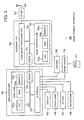
- FIG. 3 illustrates an example of the hardware of the radio terminal apparatus 100 according to the second embodiment.
- the radio terminal apparatus 100 includes an application unit 701, a baseband unit 702, a radio frequency (RF) unit 703, and an antenna 704.
- the radio terminal apparatus 100 further includes a display 705, a touch panel 706, a keypad 707, a microphone 708, a speaker 709, and a media reader 710.
- the application unit 701 includes a user core 731, an interface 732, and a bridge 733.
- the user core 731 includes a central processing unit (CPU) 731a, a random access memory (RAM) 731b, and a memory 731c.
- CPU central processing unit
- RAM random access memory
- the CPU 731a is a processor including a computing unit that executes instructions described in a program.
- the CPU 731a loads at least part of programs and data stored in the memory 731c into the RAM 731b, and executes instructions described in the program.
- the CPU 731a may include a plurality of processor cores.
- the user core 731 may include a plurality of CPUs 731a. In this case, the user core 731 is able to execute processes in parallel.
- the RAM 731b is a volatile memory that temporarily stores a program executed by the CPU 731a and data used for processing.
- the memory 731c is an example of a non-volatile storage device that stores programs such as an operating system (OS), firmware, and application software, data used for processing, and the like.
- OS operating system
- firmware firmware
- application software data used for processing, and the like.
- the user core 731 may separately include a storage device such as a flash memory, a solid state drive (SSD), and the like. Further, the user core 731 may include a plurality of storage devices.
- a storage device such as a flash memory, a solid state drive (SSD), and the like. Further, the user core 731 may include a plurality of storage devices.
- the interface 732 connects the application unit 701 to the display 705, the touch panel 706, the keypad 707, the microphone 708, the speaker 709, and the media reader 710.
- the bridge 733 allows exchange of data between the application unit 701 and the baseband unit 702.
- the user core 731, the interface 732, and the bridge 733 are connected to each other.
- the baseband unit 702 includes a bridge 751, a radio control core 752, and a CDMA signal processing unit 753.
- the bridge 751 allows exchange of data between the application unit 701 and the baseband unit 702.
- the radio control core 752 includes a CPU 752a, a RAM 752b, and a memory 752c.
- the CPU 752a is a processor including a computing unit that executes instructions described in a program.
- the CPU 752a loads at least part of programs and data stored in the memory 752c into the RAM 752b, and executes instructions described in the program.
- the CPU 752a may include a plurality of processor cores.
- the radio control core 752 may include a plurality of CPUs 752a. In this case, the radio control core 752 is able to execute processes in parallel.
- the CDMA signal processing unit 753 performs spread spectrum on a digitally modulated data signal by multiplying the data signal by a spreading code, and multiplexes a spread spectrum signal so as to generate a baseband signal.
- the RF unit 703 performs frequency conversion of the baseband signal to an RF signal, and transmits the RF signal via the antenna 704.
- the RF unit 703 receives the RF signal via the antenna 704, and performs frequency conversion of the RF signal to a baseband signal.
- the CDMA signal processing unit 753 decodes the baseband signal so as to generate a data signal.
- the antenna 704 is used for transmitting and receiving radio frequency signals.
- the radio terminal apparatus 100 may include a plurality of antennas.
- the display 705 may be a display device such as a liquid crystal display (LCD), a plasma display panel (PDP), an organic electro-luminescence display (OELD), and the like, for example.
- LCD liquid crystal display
- PDP plasma display panel
- OELD organic electro-luminescence display
- the touch panel 706 and the keypad 707 are examples of input devices.
- the microphone 708 is an example of an audio input device that converts an input sound into an electrical signal.
- the speaker 709 is an example of an audio output device that outputs audio.
- the media reader 710 is a device that reads information recorded in a recording medium 711.
- the recording medium 711 may be a magnetic disk, an optical disc, a semiconductor memory, or the like.
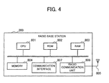
- FIG. 4 illustrates an example of the hardware of the radio base station 200 according to the second embodiment.
- the radio base station 200 includes a CPU 801, a ROM 802, a RAM 803, a memory 804, an antenna 805, a radio communication unit 806, and a communication interface 807.
- the CPU 801 is a processor including a computing unit that executes instructions described in a program.
- the CPU 801 loads at least part of programs and data stored in the ROM 802 or the memory 804 into the RAM 803, and executes instructions described in the program.
- the RAM 803 is a volatile memory that temporarily stores a program executed by the CPU 801 and data used for processing.
- the memory 804 is an example of a non-volatile storage device that stores programs such as an OS, firmware, and application software, data used for processing, and the like. Examples of the memory 804 include a flash memory, an SSD, and the like.
- the antenna 805 is used for transmitting and receiving radio frequency signals. In the example of FIG. 4 , only one antenna is illustrated. However, the radio base station 200 may include a plurality of antennas.
- the radio communication unit 806 operates in response to an instruction from the CPU 801, and controls connection and disconnection of a line for communication with the radio terminal apparatus 100.
- the radio communication unit 806 exchanges data with the radio terminal apparatus 100 via the antenna 805 by radio.
- the radio communication unit 806 performs processing such as frequency conversion from baseband signals to RF signals, error correction coding and decoding, modulation and demodulation, and the like.
- the communication interface 807 is an interface for communicating with the radio network control apparatus 300.
- FIG. 5 illustrates an example of the hardware of the radio network control apparatus 300 according to the second embodiment.
- the radio network control apparatus 300 includes a BTS interface 901, a core network interface 902, an asynchronous transfer mode (ATM) switch 903, a diversity handover unit 904, and a main control unit 905.
- ATM asynchronous transfer mode
- the BTS interface 901 is a communication interface for exchanging data with the radio base station 200.
- the core network interface 902 is a communication interface for exchanging data with, for example, the content server 500 via the core network 400.
- the ATM switch 903 is a switch that transfers, to the diversity handover unit 904 or the main control unit 905, data input from the BTS interface 901 or the core network interface 902, in an asynchronous transfer mode.
- the diversity handover unit 904 controls a plurality of radio base stations 200.
- the diversity handover unit 904 establishes a radio channel with a base station 200 of the target cell before releasing a radio channel with a radio base station 200 of the source cell.
- the diversity handover unit 904 controls diversity handover.
- the main control unit 905 includes a CPU 905a, a RAM 905b, and a memory 905c.
- the CPU 905a is a processor including a computing unit that executes instructions described in a program.
- the CPU 905a loads at least part of programs and data stored in the memory 905c into the RAM 905b, and executes instructions described in the program.
- the CPU 905a may include a plurality of processor cores.
- the main control unit 905 may include a plurality of CPUs 905a. In this case, the main control unit 905 is able to execute processes in parallel.
- the RAM 905b is a volatile memory that temporarily stores a program executed by the CPU 905a and data used for processing.
- the memory 905c is an example of a non-volatile storage device that stores programs such as an OS, firmware, and application software, data used for processing, and the like.
- the main control unit 905 may separately include a storage device such as a flash memory, an SSD, and the like. Further, the main control unit 905 may include a plurality of storage devices.
- FIG. 6 is a block diagram illustrating examples of functions of the radio terminal apparatus 100 according to the second embodiment.
- the radio terminal apparatus 100 includes a display processing unit 101, a display data storage unit 102, a stream control unit 103, a time information storage unit 104, and a data buffer 105.
- the radio terminal apparatus 100 further includes a time information transmitting unit 106, and a discontinuous communication control unit 107.
- Functions of the display processing unit 101, the display data storage unit 102, the stream control unit 103, the time information storage unit 104, and the data buffer 105 may be realized by the user core 731.
- the functions of the time information transmitting unit 106 and the discontinuous communication control unit 107 may be realized by the radio control core 752.
- the functions of the display processing unit 101 and the stream control unit 103 may be implemented as modules of a program executed by the CPU 731a.
- the functions of the display processing unit 101 and the stream control unit 103 part of or all the functions of the CPU 731a may be implemented not as software, but as an electronic circuit.
- the display data storage unit 102, the time information storage unit 104, and the data buffer 105 are storage areas reserved in the RAM 731b and the memory 731c.
- the functions of the time information transmitting unit 106 and the discontinuous communication control unit 107 may be implemented as modules of a program executed by the CPU 752a. As the functions of the time information transmitting unit 106 and the discontinuous communication control unit 107, part of or all the functions of the CPU 752a may be implemented not as software, but as an electronic circuit.
- the display processing unit 101 displays display data, such as images, text, and the like, on the display 705.
- the display processing unit 101 includes a rendering engine 111 and a data input and output unit 112.
- the rendering engine 111 generates display data in a form that may be displayed on the display 705, on the basis of data for display including a description language (such as HyperText Markup Language (HTML), Extensible Markup Language (XML), and the like), data structure information, text data, image data, and the like. In other words, the rendering engine 111 performs rendering.
- the data input and output unit 112 is an input and output unit that stores display data in the display data storage unit 102, and reads the display data from the display data storage unit 102. Also, the data input and output unit 112 exchanges data with the stream control unit 103.
- the display data storage unit 102 stores the display data generated by the rendering engine 111. For example, after the rendering engine 111 generates display data, the display data storage unit 102 temporarily stores the display data until the display data is displayed on the display 705. When the display data is read to be displayed on the display 705, the display data is deleted from the display data storage unit 102.
- the stream control unit 103 performs processing for outputting data to the user.
- the stream control unit 103 includes a time monitoring unit 131, a data input and output unit 132, and a decoding unit 133.
- the time monitoring unit 131 generates time information indicating the length of the time period during which the user is viewing or listening to the output contents (for example, images, text, audio, and the like) of the data. For instance, the time monitoring unit 131 measures the time from when the display data becomes ready for display to when the user requests the next display data (to when a data request operation is performed on the touch panel 706 or the keypad 707).
- the time monitoring unit 131 determines this time point as a time point when the display data becomes ready for display.
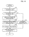
- the time monitoring unit 131 stores the measured time (measurement time) in the time information storage unit 104. Further, the time monitoring unit 131 calculates the average of the latest measurement time and previous measurement times.
- the time monitoring unit 131 extracts a predetermined number of previous measurement times in reverse chronological order, and calculates the average of the extracted previous measurement times and the latest measurement time. In the case where the number of previous measurement times is less than the predetermined number, the time monitoring unit 131 calculates the average of the existing measurement times.
- the time monitoring unit 131 stores the calculated average in the time information storage unit 104, as time information to be used for discontinuous communication control.
- the average may be expressed in units of time such as seconds, or may be expressed in units of sub-frames.
- the data input and output unit 132 is an input and output unit that exchanges data with the display processing unit 101. For example, the data input and output unit 132 transmits, to the display processing unit 101, image data that is temporarily stored in the data buffer 105.
- the decoding unit 133 performs decompression and decoding of compressed coded data, image quality enhancement processing on image data, and the like.
- the decoding unit 133 stores the processed data in the data buffer 105.
- the time information storage unit 104 stores the measurement times measured by the time monitoring unit 131 and the calculated average.
- the data buffer 105 temporarily stores image data processed by the decoding unit 133.
- the image data stored in the data buffer 105 is deleted at the point when the image data is read by the display processing unit 101 through the data input and output unit 132.
- the time information transmitting unit 106 transmits time information held by the stream control unit 103 to the radio network control apparatus 300.
- the discontinuous communication control unit 107 performs discontinuous transmission on the uplink control channel and discontinuous reception on the downlink control channel.
- the discontinuous communication control unit 107 performs DTX and DRX. In the case of performing DTX, if there is no data transmission on the uplink E-DCH (or if the amount of data is less than a predetermine amount), the discontinuous communication control unit 107 performs control such that DPCCH bursts are discontinuously transmitted. The transmission period of the DPCCH burst is determined by a parameter set by the radio network control apparatus 300. Discontinuous transmission of DPCCH bursts by DTX is referred to as a UE DTX cycle.
- the discontinuous communication control unit 107 performs control such that the downlink HS-SCCH is discontinuously monitored.
- the monitoring period of the HS-SCCH is determined by a parameter set by the radio network control apparatus 300.
- UE DRX cycle Discontinuous monitoring of the HS-SCCH by DRX is referred to as a UE DRX cycle.
- DRX is performed in combination with DTX.
- the discontinuous communication control unit 107 controls starting and stopping UE DTX and UE DRX in accordance with a control signal transmitted from the radio network control apparatus 300 on the HS-SCCH.
- the above is the functions of the radio terminal apparatus 100.
- FIG. 7 is a block diagram illustrating examples of functions of the radio network control apparatus 300 according to the second embodiment.
- the radio network control apparatus 300 includes a communication unit 301, a data acquisition unit 302, and a radio control unit 303.
- the communication unit 301, the data acquisition unit 302, and the radio control unit 303 may be implemented as modules of a program executed by the CPU 905a. Alternatively, part of or all the functions of the communication unit 301, the data acquisition unit 302, and the radio control unit 303 may be implemented not as software, but as an electronic circuit.
- the communication unit 301 is an interface for communicating with the radio base station 200.
- the communication unit 301 receives a request for data transmitted from the radio terminal apparatus 100 via the radio base station 200.
- the communication unit 301 transmits data, which is acquired from the content server 500 by the data acquisition unit 302, to the radio terminal apparatus 100 via the radio base station 200.
- the communication unit 301 transmits, to the radio base station 200, control information output from the radio control unit 303.
- the data acquisition unit 302 acquires data from the content server 500.
- the data acquisition unit 302 acquires data, such as text data, image data, audio data, and the like, from the content server 500.
- the data acquisition unit 302 inputs the data acquired from the content server 500 to the communication unit 301 so as to transmit the data to the radio terminal apparatus 100 via the radio base station 200.
- the radio control unit 303 includes a discontinuous communication control unit 331, a time information receiving unit 332, and a time information setting unit 333.
- the discontinuous communication control unit 331 controls the radio base station 200 so as to perform discontinuous transmission on the uplink control channel and discontinuous reception on the downlink control channel.
- the time information receiving unit 332 receives time information transmitted from the radio terminal apparatus 100 via the radio base station 200.
- the time information setting unit 333 sets the periods of the discontinuous transmission and discontinuous reception, on the basis of the time information received by the time information receiving unit 332.
- the time information setting unit 333 sets a parameter that determines the period of the UE DTX cycle and a parameter that determines the period of the UE DRX cycle on the basis of the time information.
- the UE DTX cycle includes UE DTX Cycle 1 for transmitting DPCCH bursts at short time intervals and UE DTX Cycle 2 for transmitting DPCCH bursts at long time intervals.
- the time information setting unit 333 sets a parameter UE_DTX_Cycle_2, which determines the period of UE DTX Cycle 2, to a value based on the time information. Further, the time information setting unit 333 may set a parameter UE_DTX_Cycle_1, which determines the period of UE DTX Cycle 1, to a value based on the time information.
- FIG. 8 illustrates discontinuous transmission on an uplink DPCCH.
- CFN represents a connection frame number.
- DPCCH transmission represents a transmission interval of the DPCCH burst (although not illustrated in FIG. 8 , a transmission interval of a preamble is present before the DPCCH burst, and a transmission interval of a postamble is present after the DPCCH burst).
- the UE DTX cycle (and the UE DRX cycle) is set and activated by a radio resource control (RRC) signal.
- RRC radio resource control
- the UE DTX cycle is not activated immediately after a call connection setting is performed, but is activated after an interval called Enabling Delay.
- the length of the Enabling Delay interval is determined by a parameter Enabling_Delay (1 frame in the example of FIG. 8 ).
- Enabling_Delay 1 frame in the example of FIG. 8 .
- the Enabling Delay interval continuous transmission on the uplink DPCCH and continuous reception on the F-DPCH are performed.
- transmission on the E-DCH is restricted.
- the UE DTX cycle After the Enabling Delay interval, the UE DTX cycle is started.
- the UE DTX cycle includes UE DTX Cycle 1 for transmitting DPCCH bursts at short time intervals and UE DTX Cycle 2 for transmitting DPCCH bursts at long time intervals.
- the transmission period of the DPCCH burst in the interval of UE DTX Cycle 1 is determined by the parameter UE_DTX_Cycle_1 (4 sub-frames in the example of FIG. 8 ).
- the transmission period of the DPCCH burst in the interval of UE DTX Cycle 2 is determined by the parameter UE_DTX_Cycle_2 (8 sub-frames in the example of FIG. 8 ).
- UE_DTX_Cycle_2 is often set to an integer multiple of UE_DTX_Cycle_1.
- the length of the transmission interval of the DPCCH burst in UE DTX Cycle 1 is determined by a parameter UE_DPCCH_Burst_1.
- the length of the transmission interval of the DPCCH burst in UE DTX Cycle 2 is determined by a parameter UE_DPCCH_Burst_2.
- UE DTX Cycle 1 After the Enabling Delay interval, UE DTX Cycle 1 is started. If there is no E-DCH transmission for a predetermined time period in UE DTX Cycle 1, the radio terminal apparatus 100 switches the UE DTX cycle to UE DTX Cycle 2. The length of the predetermined time period is determined by a parameter MAC_Inactivity_Threshold (8 sub-frames in the example of FIG. 8 ).
- the radio terminal apparatus 100 If transmission on the E-DCH occurs (at CFN 65, Sub-frame 1 in the example of FIG. 8 ) in the interval of UE DTX Cycle 2, the radio terminal apparatus 100 transmits the DPCCH in the transmission time interval (TTI) in which transmission on the E-DCH occurs. Further, the radio terminal apparatus 100 switches the UE DTX cycle from UE DTX Cycle 2 to UE DTX Cycle 1 in a TTI after the transmission on the E-DCH.
- TTI transmission time interval
- the radio terminal apparatus 100 If transmission on the E-DCH occurs in the interval of UE DTX Cycle 1, the radio terminal apparatus 100 immediately transmits the DPCCH. If there is no E-DCH transmission for a time period determined by MAC_Inactivity_Threshold, the radio terminal apparatus 100 switches the UE DTX cycle to UE DTX Cycle 2 again.
- the discontinuous transmission period of the DPCCH burst is determined by the parameters UE_DTX_Cycle_1 and UE_DTX_Cycle_2. Accordingly, it is possible to adjust the interval for transmitting the DPCCH burst by controlling the parameters UE-DTX_Cycle_1 and UE_DTX_Cycle_2.
- FIG. 9 illustrates discontinuous reception on a downlink High-Speed Shared Control Channel (HS-SCCH).
- HS-SCCH High-Speed Shared Control Channel
- P-CCPCH is an example of a broadcast channel.
- SFN represents a sub-frame number.
- S_DRX represents a sub-frame number.
- the radio terminal apparatus 100 receives part of the HS-SCCH, HS-PDSCH, and HS-DPCCH (sub-frames indicated by hatching (reception sub-frames) in the example of FIG. 9 ).
- the time interval for receiving reception sub-frames on the HS-SCCH is determined by a parameter UE_DRX_Cycle.
- the reception timings of reception sub-frames on the HS-PDSCH and HS-DPCCH are determined in accordance with the reception timing of reception sub-frames on the HS-SCCH.
- This predetermined time period is determined by time T0 and time T1 illustrated in FIG. 9 .
- the radio terminal apparatus 100 After a lapse of a predetermined time period from the start of the discontinuous reception of the HS-SCCH in the UE DRX cycle, the radio terminal apparatus 100 starts discontinuous reception of the HS-PDSCH and HS-DPCCH.
- FIG. 10 illustrates examples of parameters used for discontinuous transmission on the uplink DPCCH and discontinuous reception on the HS-SCCH.
- UE_DTX_Cycle_1 is a parameter that determines the discontinuous transmission period of UE DTX Cycle 1.
- DPCCH bursts are transmitted at time intervals indicated by UE_DTX_Cycle_1.
- the length of the DPCCH burst in UE DTX Cycle 1 is determined by the parameter UE_DPCCH_Burst_1.
- the value of UE_DTX_Cycle_1 is given in units of sub-frames, in accordance with the E-DCH TTI.
- UE_DTX_Cycle_2 is a parameter that determines the discontinuous transmission period of UE DTX Cycle 2.
- DPCCH bursts are transmitted at time intervals indicated by UE_DTX_Cycle_2.
- the length of the DPCCH burst in UE DTX Cycle 2 is determined by the parameter UE_DPCCH_Burst_2.
- the value of UE_DTX_Cycle_2 is given in units of sub-frames, in accordance with the E-DCH TTI.
- MAC_Inactivity_Threshold is a parameter which is referred to when UE DTX Cycle 1 is switched to UE DTX Cycle 2.
- the radio terminal apparatus 100 switches the UE DTX cycle to UE DTX Cycle 2.
- the value of MAC_Inactivity_Threshold is given in units of E-DCH TTIs. Note that when the value of MAC_Inactivity_Threshold is set to infinity, it is possible to operate only with UE DTX Cycle 1.
- parameters such as UE_DRX_Cycle and the like are used. Although not described herein, parameters such as those indicating predetermined time periods for determining the timings for staring discontinuous reception on the HS-SCCH, HS-PDSCH, and HS-DPCCH are also used for discontinuous reception on the downlink HS-SCCH, for example.
- UE_DRX_Cycle determines the time interval for receiving reception sub-frames on the HS-SCCH. The value of UE_DRX_Cycle is given in units of sub-frames.
- the setting values illustrated in the example of FIG. 10 are prescribed values that are usually used in the W-CDMA system.
- the radio network control apparatus 300 adjusts at least one of UE_DTX_Cycle_1, UE_DTX_Cycle_2, and UE_DRX_Cycle for each radio terminal apparatus 100. More specifically, the radio network control apparatus 300 adjusts at least one of UE_DTX_Cycle_1, UE_DTX_Cycle_2, and UE_DRX_Cycle to a value corresponding to the time information transmitted from the radio terminal apparatus 100.
- FIG. 11 is a first diagram illustrating an example of a data unit transmitted on the E-DCH.
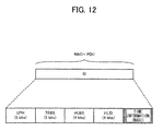
- FIG. 12 is a second diagram illustrating an example of a data unit transmitted on the E-DCH.
- a MAC PDU format of MAC-i/is is illustrated as an example.
- a MAC PDU format of MAC-e/es may also be applicable to the technique of the second embodiment.
- a MAC-i PDU contains MAC-i headers and MAC-is PDUs.
- the same number of MAC-i headers as the number of MAC-is PDUs contained in the MAC-i PDU are generated, and are added to the MAC-i PDU.
- the MAC-i PDU also contains a scheduling information (SI) message.
- the SI message contains a UE power headroom (UPH) field and a total E-DCH buffer status (TEBS) field.
- the SI message also contains a highest priority logical buffer status (HLBS) field and a highest priority logical channel ID (HLID) field. Note that the top bit of the UPH field is the most significant bit (MSB).
- the UPH field contains a 5-bit indicator indicating the ratio of the maximum transmission power of the radio terminal apparatus 100 and the corresponding DPCCH code power.
- the TEBS field contains a 5-bit identifier that identifies the total amount of data available across all logical channels. The identifier contained in the TEBS field identifies the amount of data in bytes that is available for transmission and retransmission at a radio link control (RLC).
- RLC radio link control
- the HLBS field contains an indicator that indicates the ratio of the amount of data available from the highest priority logical channel.
- the HLID field contains a 4-bit identifier that identifies the highest priority logical channel (a logical channel that occupies the greatest amount of buffer resources).
- the SI message of the second embodiment also contains a non access span information (NASI) field.
- the NASI field contains a 4-bit identifier that identifies the time information to be transmitted from the radio terminal apparatus 100 to the radio network control apparatus 300.
- a MAC-i PDU may be formed with an SI message, and the SI message may contain a NASI field.
- FIG. 13 illustrates an example of a method of generating time information according to the second embodiment.
- the time information generated herein indicates the length of the time period during which the user is viewing or listening to the output results of data after the data becomes ready for output in the radio terminal apparatus 100.
- the time information indicates the length of the time period during which the user is browsing web sites so as to view videos and pictures, listen to audio and music, or to read text.
- processing related to image data decoding, image quality enhancement processing, and the like
- reception of image data and the like are rarely performed, for instance.
- a method is proposed that adjusts the periods of the UE DTX cycle and UE DRX cycle using the time information indicating the length of this time period.
- the time information is generated using a function of the stream control unit 103 of the radio terminal apparatus 100.
- the following is an example of a method of generating time information when image data is received.
- the decoding unit 133 performs decoding, image quality enhancement processing, and the like, and stores the processed image data in the data buffer 105.
- the display processing unit 101 reads the image data through the data input and output unit 132. Thus, an image is displayed on the display 705 by the display processing unit 101.
- the display processing unit 101 Upon completion of reception of the image data from the stream control unit 103, the display processing unit 101 notifies the stream control unit 103 of completion of the reception of the image data.
- the display processing unit 101 generates display data by causing the rendering engine 111 to render the image data, and temporarily stores the rendered image data in the display data storage unit 102. Then, the display processing unit 101 reads the display data from the display data storage unit 102, and displays the display data on the display 705. After reading the display data, the display processing unit 101 deletes the read display data from the display data storage unit 102.
- the time monitoring unit 131 When the time monitoring unit 131 confirms that the stream control unit 103 has received the reception completion notification from the display processing unit 101 and that no data is stored in the data buffer 105, the time monitoring unit 131 starts the timer.
- the timer is a timing device that measures the time from when the timer is started and to when the timer is stopped.
- the time monitoring unit 131 stops the timer. Then, the time monitoring unit 131 stores a record indicating the time (measurement time) from when the timer is started to when the timer is stopped, in the time information storage unit 104. Further, the time monitoring unit 131 calculates the average of the previously measured measurement times and the currently measured measurement time. The time monitoring unit 131 calculates the average using a method illustrated in FIG. 13 .
- the time monitoring unit 131 reads a predetermined number of records of previous measurement times from the time information storage unit 104. In the example of FIG. 13 , four records of previous measurement times are read in reverse chronological order. The time monitoring unit 131 calculates the average measurement time using the records read from the time information storage unit 104.
- the time monitoring unit 131 generates time information (corresponding to 50 sub-frames in the example of FIG. 13 ) on the basis of the average. Note that the time information may be converted into units of sub-frames.
- FIG. 14 illustrates an example of a method of using time information according to the second embodiment.
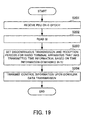
- the time information setting unit 333 converts the value of time information expressed in units of seconds or the like into units of sub-frames or the like (the same units as those of UE_DTX_Cycle_1, UE_DTX_Cycle_2, and UE_DRX_Cycle).
- the value of time information may be directly converted into units of sub-frames or the like on the basis of the length of the E-DCH TTI. In the second embodiment, however, a method of converting time information using determination conditions illustrated in FIG. 14 is proposed.
- q+1 thresholds Th(0), ... , and Th(q) (T(0) > T(1) > ... > T(q-1) > T(q)) are prepared.
- a value is assigned to each of ranges defined by two adjacent thresholds. Then, a determination is made as to which range the value of time information falls in. Thus, a value assigned to the range in which the value of the time information is determined to fall is selected.
- Information of a table for associating determination conditions with converted values may be stored in advance in the time information setting unit 333.
- the time information setting unit 333 refers to the table and selects a value assigned to the range in which the value indicated by the time information falls.
- a "PRESCRIBED VALUE" in the table of FIG. 14 indicates a prescribed value (examples of parameters illustrated in FIG. 10 ) that is usually used in the W-CDMA system, for example.
- the value of time information selected in the manner described above is set as the discontinuous communication period of the UE DTX cycle or the UE DRX cycle.
- the value set as the discontinuous communication period is transmitted from the radio network control apparatus 300 to the radio terminal apparatus 100 as a CPC parameter, when CPC is started.
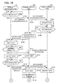
- FIG. 15 illustrates operations performed by the radio network control apparatus 300 and the radio terminal apparatus 100 when starting CPC control. Note that operations in steps S11 through S13 are performed by the radio network control apparatus 300. Operations in steps S14 and S15 are performed by the radio terminal apparatus 100.
- FIG. 16 there is illustrated a first diagram of exemplary operations performed by the radio terminal apparatus 100 when carrying out discontinuous transmission and reception control according to the second embodiment.
- the stream control unit 103 calculates the average of the measurement time #1 and the previously measured measurement time.
- the stream control unit 103 generates time information on the basis of the calculated average measurement time, and stores the time information in the time information storage unit 104. In this step, it is assumed that a record of a previously measured measurement time is not stored in the time information storage unit 104. Thus, the stream control unit 103 stores the measurement time #1 as time information.
- FIG. 17 there is illustrated a second diagram of exemplary operations performed by the radio terminal apparatus 100 when carrying out discontinuous transmission and reception control according to the second embodiment.
- the radio control core 752 inserts the time information into an SI field of a MA-i PDU, and transmits the time information to the radio network control apparatus 300 on the E-DPDCH.
- the radio network control apparatus 300 becomes able to set parameters that determine the periods of the UE DTX cycle and UE DRX cycle on the basis of the time information.
- the stream control unit 103 calculates the average of the measurement time #2 and the previously measured measurement time. In this step, since the record of the measurement time #1 is already stored in the time information storage unit 104, the stream control unit 103 calculates the average of the measurement time #1 and the measurement time #2. The stream control unit 103 stores the calculated average measurement time as time information in the time information storage unit 104.
- the display processing unit 101, the stream control unit 103, and the radio control core 752 repeat the respective processes illustrated in FIG. 17 .
- the process returns to A of FIG. 17 .
- the stream control unit 103 finishes the operation of step S135 the process returns to B of FIG. 17 .
- the radio control core 752 finishes the operation of step S136 the process returns to C of FIG. 17 . Note that each time the process is repeated, different sets of data are processed by the display processing unit 101, the stream control unit 103, and the radio control core 752.
- FIG. 18 illustrates exemplary operations performed by the radio terminal apparatus 100 when calculating an average according to the second embodiment.
- FIG. 19 illustrates exemplary operations performed by the radio network control apparatus 300 when carrying out discontinuous transmission and reception control according to the second embodiment.
- the value of the time information may be directly converted into units of sub-frames or the like on the basis of the length of the E-DCH TTI. Alternatively, the value of the time information may be converted using determination parameters illustrated in FIG. 14 .
- the radio network control apparatus 300 sets at least one of UE_DTX_Cycle_1, UE_DTX_Cycle_2, and UE_DRX_Cycle to a value based on the time information, for example.
- the value based on the time information may be (A) a value indicated by the time information, (B) a value adjusted for each parameter with reference to a value indicated by the time information, or the like.
- a method of using the value of (A) there may be a method that sets UE_DTX_Cycle_2 to infinity, and sets only UE_DTX_Cycle_1 to the value indicated by the time information.
- a method of using the value of (B) there may be a method that sets UE_DTX_Cycle_1 to the value indicated by the time information, and sets UE_DTX_Cycle_2 to an integer multiple of UE_DTX_Cycle_1. Further, there may be a method that sets UE_DTX_Cycle_2 to the value indicated by the time information, and sets UE_DTX_Cycle_1 to an integer division of UE_DTX_Cycle_2. Note that there may be a method that is used in combination with either one of the above methods and sets UE_DRX_Cycle to the value indicated by the time information.
- the discontinuous transmission and reception intervals in CPC are adjusted for each radio terminal apparatus 100, on the basis of time information indicating the time from when data output is started to when the next data is requested. This allows the radio terminal apparatus 100 to discontinuously operate on the basis of the time during which the user does not request data. Thus, it is possible to reduce power consumption of the radio terminal apparatus 100.
- the discontinuous communication period is adjusted in accordance with time information indicating the time from when image data is displayed to when acquisition of the next image data is requested.
- time information may be adjusted for each type of data, in accordance with the type of data.
- first time information that is obtained when the user is viewing images and second time information that is obtained when the user is listening to music may be separately calculated.
- an adjustment may be made on the basis of the first time information upon using image software, and an adjustment may be made on the basis of the second time information upon using music software.
- a modification may be made such that the stream control unit 103 of the radio terminal apparatus 100 calculates time information for each type of data, and selects time information to be transmitted to the radio network control apparatus 300 in accordance with the type of an application to be used, for example.
Landscapes
- Engineering & Computer Science (AREA)
- Computer Networks & Wireless Communication (AREA)
- Signal Processing (AREA)
- Mobile Radio Communication Systems (AREA)
Applications Claiming Priority (1)
| Application Number | Priority Date | Filing Date | Title |
|---|---|---|---|
| JP2013058643A JP6094297B2 (ja) | 2013-03-21 | 2013-03-21 | 無線端末装置、通信制御装置、及び無線通信方法 |
Publications (1)
| Publication Number | Publication Date |
|---|---|
| EP2809100A1 true EP2809100A1 (en) | 2014-12-03 |
Family
ID=49916973
Family Applications (1)
| Application Number | Title | Priority Date | Filing Date |
|---|---|---|---|
| EP20140150104 Withdrawn EP2809100A1 (en) | 2013-03-21 | 2014-01-03 | Apparatuses and method for controlling a discontinuous communication mode |
Country Status (3)
| Country | Link |
|---|---|
| US (1) | US9282480B2 (ja) |
| EP (1) | EP2809100A1 (ja) |
| JP (1) | JP6094297B2 (ja) |
Cited By (2)
| Publication number | Priority date | Publication date | Assignee | Title |
|---|---|---|---|---|
| EP2963961A4 (en) * | 2013-04-02 | 2016-03-30 | Huawei Tech Co Ltd | METHOD AND APPARATUS FOR TRANSMITTING A DEDICATED CHANNEL |
| WO2022068553A1 (zh) * | 2020-09-29 | 2022-04-07 | 腾讯科技(深圳)有限公司 | 车辆通信方法、装置、计算机可读介质及电子设备 |
Families Citing this family (5)
| Publication number | Priority date | Publication date | Assignee | Title |
|---|---|---|---|---|
| KR102036579B1 (ko) * | 2012-11-09 | 2019-10-28 | 삼성전자주식회사 | 무선 통신 시스템에서 웹 서비스 제공 방법 및 장치 |
| US10412591B2 (en) * | 2014-07-25 | 2019-09-10 | Apple Inc. | Simultaneous VoLTE and 2G/3G/LTE data in dual SIM configuration |
| DE102016212002B4 (de) | 2016-03-16 | 2018-05-09 | Volkswagen Aktiengesellschaft | Verfahren zum Betreiben einer Mobilfunkstation, sowie Relaisfunkstation und Mobilfunkstation zur Verwendung bei dem Verfahren |
| US11032871B2 (en) * | 2016-07-27 | 2021-06-08 | Telefonaktiebolaget Lm Ericsson (Publ) | Managing sleep cycles in a wireless communications system |
| US10925007B2 (en) | 2018-11-02 | 2021-02-16 | Apple Inc. | Dynamic power reduction requests for wireless communications |
Citations (5)
| Publication number | Priority date | Publication date | Assignee | Title |
|---|---|---|---|---|
| JP2005026991A (ja) | 2003-07-01 | 2005-01-27 | Ntt Docomo Inc | 移動通信システム、無線基地局、移動局、チャネル送信制御方法およびチャネル送信制御プログラム |
| US20090201843A1 (en) * | 2008-02-13 | 2009-08-13 | Huaiyuan Wang | Using traffic patterns to improve sleep mode efficiency in a radio handset |
| US20100002615A1 (en) * | 2008-07-07 | 2010-01-07 | Maruti Gupta | Mobile station and method for dynamically switching sleep cycles without deactivating a current power savings class (psc) |
| EP2519060A1 (en) * | 2011-04-28 | 2012-10-31 | Alcatel Lucent | Power saving mode adjustment |
| EP2547166A1 (en) * | 2011-07-11 | 2013-01-16 | Samsung Electronics Co., Ltd. | Method for controlling discontinuous reception in mobile communication device |
Family Cites Families (22)
| Publication number | Priority date | Publication date | Assignee | Title |
|---|---|---|---|---|
| US6377790B1 (en) * | 1999-03-08 | 2002-04-23 | Sharp Laboratories Of America, Inc. | Mobile-initiated, packet switched communications method |
| RU2345489C2 (ru) * | 2004-05-07 | 2009-01-27 | Самсунг Электроникс Ко., Лтд. | Система и способ для периодического регулирования в режиме ожидания в системе связи с шбд |
| JP4664772B2 (ja) * | 2005-08-18 | 2011-04-06 | 三菱電機株式会社 | 間欠送受信システム及び間欠送受信管理方法 |
| US8625601B2 (en) * | 2005-10-31 | 2014-01-07 | Qualcomm Incorporated | Method and apparatus for low-overhead packet data transmission and control of reception mode |
| JP2007316934A (ja) * | 2006-05-25 | 2007-12-06 | Fujitsu Ltd | 情報処理装置、情報処理方法及びプログラム |
| KR100938754B1 (ko) * | 2006-10-30 | 2010-01-26 | 엘지전자 주식회사 | 비연속 수신을 이용한 데이터 수신 및 전송 방법 |
| ES2661673T3 (es) * | 2007-01-30 | 2018-04-03 | Interdigital Technology Corporation | Control del ajuste de la longitud del ciclo de DRX implícito en el modo activo de LTE |
| US8169957B2 (en) * | 2007-02-05 | 2012-05-01 | Qualcomm Incorporated | Flexible DTX and DRX in a wireless communication system |
| JP5583975B2 (ja) * | 2007-02-06 | 2014-09-03 | ノキア コーポレイション | 効率的な不連続通信を提供する方法及び装置 |
| JP4932521B2 (ja) * | 2007-02-09 | 2012-05-16 | 株式会社エヌ・ティ・ティ・ドコモ | 移動通信システムで使用される基地局装置及び方法 |
| JP5650407B2 (ja) * | 2007-03-26 | 2015-01-07 | サムスン エレクトロニクス カンパニー リミテッド | 移動通信システムにおけるユーザー端末の不連続受信方法及び装置 |
| FI20085104A0 (fi) * | 2008-02-06 | 2008-02-06 | Nokia Corp | Menetelmä ja järjestelmä epäjatkuvan vastaanoton/lähetyksen ohjaamiseksi |
| US8229434B2 (en) * | 2008-11-10 | 2012-07-24 | Telefonaktiebolaget Lm Ericsson (Publ) | Using mobility statistics to enhance telecommunications handover |
| AU2011215752A1 (en) * | 2010-02-12 | 2012-09-06 | Interdigital Patent Holdings, Inc | Access control and congestion control in machine-to-machine communication |
| KR101664279B1 (ko) * | 2010-02-16 | 2016-10-12 | 삼성전자주식회사 | 무선 통신 시스템에서 불연속 수신을 위한 제어 방법 및 장치 |
| US8744534B2 (en) * | 2010-04-30 | 2014-06-03 | Apple Inc. | Methods and apparatus for preserving battery resources in a mobile communication device |
| JP5466580B2 (ja) * | 2010-05-28 | 2014-04-09 | 株式会社Nttドコモ | 無線通信システム及び間欠送信方法 |
| CA2816921C (en) * | 2010-11-08 | 2018-03-13 | Research In Motion Limited | Wireless resources |
| US8886132B2 (en) * | 2011-03-08 | 2014-11-11 | Skype | Controlling power saving mode in radio |
| CN102595574A (zh) * | 2011-08-09 | 2012-07-18 | 北京新岸线无线技术有限公司 | 节电方法及装置 |
| US20140295820A1 (en) * | 2011-10-27 | 2014-10-02 | Samsung Electronics Co., Ltd | Method and apparatus for effectively reducing power consumption of terminal in mobile communication system |
| US9736812B2 (en) * | 2012-01-23 | 2017-08-15 | Deutsche Telekom Ag | Method for using a user equipment with a first public land mobile network and with a second public land mobile network, user equipment, program and computer program product |
-
2013
- 2013-03-21 JP JP2013058643A patent/JP6094297B2/ja not_active Expired - Fee Related
-
2014
- 2014-01-03 EP EP20140150104 patent/EP2809100A1/en not_active Withdrawn
- 2014-01-08 US US14/150,407 patent/US9282480B2/en not_active Expired - Fee Related
Patent Citations (5)
| Publication number | Priority date | Publication date | Assignee | Title |
|---|---|---|---|---|
| JP2005026991A (ja) | 2003-07-01 | 2005-01-27 | Ntt Docomo Inc | 移動通信システム、無線基地局、移動局、チャネル送信制御方法およびチャネル送信制御プログラム |
| US20090201843A1 (en) * | 2008-02-13 | 2009-08-13 | Huaiyuan Wang | Using traffic patterns to improve sleep mode efficiency in a radio handset |
| US20100002615A1 (en) * | 2008-07-07 | 2010-01-07 | Maruti Gupta | Mobile station and method for dynamically switching sleep cycles without deactivating a current power savings class (psc) |
| EP2519060A1 (en) * | 2011-04-28 | 2012-10-31 | Alcatel Lucent | Power saving mode adjustment |
| EP2547166A1 (en) * | 2011-07-11 | 2013-01-16 | Samsung Electronics Co., Ltd. | Method for controlling discontinuous reception in mobile communication device |
Cited By (2)
| Publication number | Priority date | Publication date | Assignee | Title |
|---|---|---|---|---|
| EP2963961A4 (en) * | 2013-04-02 | 2016-03-30 | Huawei Tech Co Ltd | METHOD AND APPARATUS FOR TRANSMITTING A DEDICATED CHANNEL |
| WO2022068553A1 (zh) * | 2020-09-29 | 2022-04-07 | 腾讯科技(深圳)有限公司 | 车辆通信方法、装置、计算机可读介质及电子设备 |
Also Published As
| Publication number | Publication date |
|---|---|
| US9282480B2 (en) | 2016-03-08 |
| JP2014183550A (ja) | 2014-09-29 |
| US20140287789A1 (en) | 2014-09-25 |
| JP6094297B2 (ja) | 2017-03-15 |
Similar Documents
| Publication | Publication Date | Title |
|---|---|---|
| JP6368819B2 (ja) | コンポーネント・キャリアを監視および処理するための方法および装置 | |
| EP2809100A1 (en) | Apparatuses and method for controlling a discontinuous communication mode | |
| EP2634950B1 (en) | Method and Apparatus for Power Headroom Reporting | |
| JP5641630B2 (ja) | 測定情報を報告するための方法及び装置 | |
| JP2021005902A (ja) | 基地局、User Equipment、及びこれらの方法 | |
| JP5530526B2 (ja) | タイミング制御 | |
| US12101716B2 (en) | User equipment involved in transmitting UE assistance information | |
| JP5331509B2 (ja) | バッファ状態報告を実行する方法及び通信装置 | |
| JP2015523041A (ja) | 無線ネットワークにおけるユーザ機器支援情報の信号伝達 | |
| EP2850891B1 (en) | Multireceiver timing advance provisioning | |
| RU2605367C2 (ru) | Способ обработки доступа к каналу и соответствующее устройство | |
| JP2011030197A (ja) | スケジューリングリクエストの方法及び通信装置 | |
| US20230413178A1 (en) | Methods for Discontinuous Reception (DRX) in Conjunction with Guaranteed Low-Latency Services | |
| WO2020093908A1 (en) | Method and apparatus for scheduling uplink transmission | |
| JP2017500815A (ja) | ワイヤレス通信ネットワークにおける最大電力報告イベントをトリガするための装置および方法 | |
| KR20170009861A (ko) | 2개 또는 그 초과의 캐리어들 상에서의 업링크 송신들을 용이하게 하기 위한 디바이스들 및 방법들 | |
| US9814083B2 (en) | Method and apparatus for establishing a channel | |
| US20160057804A1 (en) | Optimizing Channel State Switch based on the Traffic Volume Indicator (TVI) Values Associated with Throughputs on the Communication Links | |
| US9479294B2 (en) | Wireless transmission control for improved aggregated cell throughput capacity and signaling reliability | |
| WO2023248692A1 (ja) | 基地局装置、端末装置、及び方法 | |
| JP2014042333A (ja) | タイミング制御 | |
| KR20080051926A (ko) | 이동 통신 시스템에서 이동 단말의 상태 천이를 제어하는방법 및 장치 | |
| KR20090120792A (ko) | 이동통신 시스템에서 상향링크 전송을 위한 스케쥴링 장치및 방법 |
Legal Events
| Date | Code | Title | Description |
|---|---|---|---|
| PUAI | Public reference made under article 153(3) epc to a published international application that has entered the european phase |
Free format text: ORIGINAL CODE: 0009012 |
|
| 17P | Request for examination filed |
Effective date: 20140103 |
|
| AK | Designated contracting states |
Kind code of ref document: A1 Designated state(s): AL AT BE BG CH CY CZ DE DK EE ES FI FR GB GR HR HU IE IS IT LI LT LU LV MC MK MT NL NO PL PT RO RS SE SI SK SM TR |
|
| AX | Request for extension of the european patent |
Extension state: BA ME |
|
| R17P | Request for examination filed (corrected) |
Effective date: 20150511 |
|
| RBV | Designated contracting states (corrected) |
Designated state(s): AL AT BE BG CH CY CZ DE DK EE ES FI FR GB GR HR HU IE IS IT LI LT LU LV MC MK MT NL NO PL PT RO RS SE SI SK SM TR |
|
| RIC1 | Information provided on ipc code assigned before grant |
Ipc: H04W 88/08 20090101ALI20171025BHEP Ipc: H04W 76/04 20090101AFI20171025BHEP Ipc: H04W 52/02 20090101ALI20171025BHEP Ipc: H04W 24/08 20090101ALI20171025BHEP Ipc: H04W 88/02 20090101ALI20171025BHEP |
|
| GRAP | Despatch of communication of intention to grant a patent |
Free format text: ORIGINAL CODE: EPIDOSNIGR1 |
|
| STAA | Information on the status of an ep patent application or granted ep patent |
Free format text: STATUS: GRANT OF PATENT IS INTENDED |
|
| INTG | Intention to grant announced |
Effective date: 20171220 |
|
| STAA | Information on the status of an ep patent application or granted ep patent |
Free format text: STATUS: THE APPLICATION IS DEEMED TO BE WITHDRAWN |
|
| 18D | Application deemed to be withdrawn |
Effective date: 20180501 |