EP2809085B1 - Device for estimating placement of physical objects - Google Patents
Device for estimating placement of physical objects Download PDFInfo
- Publication number
- EP2809085B1 EP2809085B1 EP13825770.4A EP13825770A EP2809085B1 EP 2809085 B1 EP2809085 B1 EP 2809085B1 EP 13825770 A EP13825770 A EP 13825770A EP 2809085 B1 EP2809085 B1 EP 2809085B1
- Authority
- EP
- European Patent Office
- Prior art keywords
- objects
- microphones
- object position
- acoustic wave
- microphone
- Prior art date
- Legal status (The legal status is an assumption and is not a legal conclusion. Google has not performed a legal analysis and makes no representation as to the accuracy of the status listed.)
- Active
Links
- 239000013598 vector Substances 0.000 claims description 128
- 239000011159 matrix material Substances 0.000 claims description 105
- 238000000034 method Methods 0.000 claims description 38
- 230000004044 response Effects 0.000 claims description 36
- 238000005259 measurement Methods 0.000 claims description 33
- 238000012545 processing Methods 0.000 claims description 10
- 230000006870 function Effects 0.000 claims description 5
- 238000010586 diagram Methods 0.000 description 43
- 241000282414 Homo sapiens Species 0.000 description 21
- 238000012360 testing method Methods 0.000 description 18
- 238000013459 approach Methods 0.000 description 11
- 238000002474 experimental method Methods 0.000 description 10
- 230000008569 process Effects 0.000 description 8
- 238000009795 derivation Methods 0.000 description 7
- 101100095854 Schizosaccharomyces pombe (strain 972 / ATCC 24843) skp1 gene Proteins 0.000 description 5
- 101100275292 Xenopus laevis coil gene Proteins 0.000 description 5
- 101150101986 sph1 gene Proteins 0.000 description 5
- 101150074925 sph2 gene Proteins 0.000 description 5
- 238000003491 array Methods 0.000 description 4
- 238000004422 calculation algorithm Methods 0.000 description 4
- 230000009466 transformation Effects 0.000 description 4
- 230000009286 beneficial effect Effects 0.000 description 3
- 238000004891 communication Methods 0.000 description 2
- 230000000694 effects Effects 0.000 description 2
- 238000011156 evaluation Methods 0.000 description 2
- 230000002068 genetic effect Effects 0.000 description 2
- 238000005457 optimization Methods 0.000 description 2
- 238000013139 quantization Methods 0.000 description 2
- 238000005070 sampling Methods 0.000 description 2
- 230000002123 temporal effect Effects 0.000 description 2
- OMPJBNCRMGITSC-UHFFFAOYSA-N Benzoylperoxide Chemical compound C=1C=CC=CC=1C(=O)OOC(=O)C1=CC=CC=C1 OMPJBNCRMGITSC-UHFFFAOYSA-N 0.000 description 1
- 101100505320 Caenorhabditis elegans gpa-16 gene Proteins 0.000 description 1
- 241000282412 Homo Species 0.000 description 1
- 101100533558 Mus musculus Sipa1 gene Proteins 0.000 description 1
- 230000003466 anti-cipated effect Effects 0.000 description 1
- 230000015572 biosynthetic process Effects 0.000 description 1
- 238000004364 calculation method Methods 0.000 description 1
- 238000004590 computer program Methods 0.000 description 1
- 239000000470 constituent Substances 0.000 description 1
- 230000007423 decrease Effects 0.000 description 1
- 238000005516 engineering process Methods 0.000 description 1
- 239000000284 extract Substances 0.000 description 1
- 229940011939 fostex Drugs 0.000 description 1
- 238000003384 imaging method Methods 0.000 description 1
- 230000004807 localization Effects 0.000 description 1
- 230000033001 locomotion Effects 0.000 description 1
- 230000003287 optical effect Effects 0.000 description 1
- NRNCYVBFPDDJNE-UHFFFAOYSA-N pemoline Chemical compound O1C(N)=NC(=O)C1C1=CC=CC=C1 NRNCYVBFPDDJNE-UHFFFAOYSA-N 0.000 description 1
- 230000001902 propagating effect Effects 0.000 description 1
- 230000009467 reduction Effects 0.000 description 1
- 230000000630 rising effect Effects 0.000 description 1
Images


Classifications
-
- G—PHYSICS
- G01—MEASURING; TESTING
- G01S—RADIO DIRECTION-FINDING; RADIO NAVIGATION; DETERMINING DISTANCE OR VELOCITY BY USE OF RADIO WAVES; LOCATING OR PRESENCE-DETECTING BY USE OF THE REFLECTION OR RERADIATION OF RADIO WAVES; ANALOGOUS ARRANGEMENTS USING OTHER WAVES
- G01S5/00—Position-fixing by co-ordinating two or more direction or position line determinations; Position-fixing by co-ordinating two or more distance determinations
- G01S5/18—Position-fixing by co-ordinating two or more direction or position line determinations; Position-fixing by co-ordinating two or more distance determinations using ultrasonic, sonic, or infrasonic waves
- G01S5/30—Determining absolute distances from a plurality of spaced points of known location
-
- H—ELECTRICITY
- H04—ELECTRIC COMMUNICATION TECHNIQUE
- H04R—LOUDSPEAKERS, MICROPHONES, GRAMOPHONE PICK-UPS OR LIKE ACOUSTIC ELECTROMECHANICAL TRANSDUCERS; DEAF-AID SETS; PUBLIC ADDRESS SYSTEMS
- H04R1/00—Details of transducers, loudspeakers or microphones
- H04R1/20—Arrangements for obtaining desired frequency or directional characteristics
- H04R1/32—Arrangements for obtaining desired frequency or directional characteristics for obtaining desired directional characteristic only
- H04R1/40—Arrangements for obtaining desired frequency or directional characteristics for obtaining desired directional characteristic only by combining a number of identical transducers
- H04R1/403—Arrangements for obtaining desired frequency or directional characteristics for obtaining desired directional characteristic only by combining a number of identical transducers loud-speakers
-
- H—ELECTRICITY
- H04—ELECTRIC COMMUNICATION TECHNIQUE
- H04R—LOUDSPEAKERS, MICROPHONES, GRAMOPHONE PICK-UPS OR LIKE ACOUSTIC ELECTROMECHANICAL TRANSDUCERS; DEAF-AID SETS; PUBLIC ADDRESS SYSTEMS
- H04R1/00—Details of transducers, loudspeakers or microphones
- H04R1/20—Arrangements for obtaining desired frequency or directional characteristics
- H04R1/32—Arrangements for obtaining desired frequency or directional characteristics for obtaining desired directional characteristic only
- H04R1/40—Arrangements for obtaining desired frequency or directional characteristics for obtaining desired directional characteristic only by combining a number of identical transducers
- H04R1/406—Arrangements for obtaining desired frequency or directional characteristics for obtaining desired directional characteristic only by combining a number of identical transducers microphones
-
- H—ELECTRICITY
- H04—ELECTRIC COMMUNICATION TECHNIQUE
- H04R—LOUDSPEAKERS, MICROPHONES, GRAMOPHONE PICK-UPS OR LIKE ACOUSTIC ELECTROMECHANICAL TRANSDUCERS; DEAF-AID SETS; PUBLIC ADDRESS SYSTEMS
- H04R29/00—Monitoring arrangements; Testing arrangements
-
- H—ELECTRICITY
- H04—ELECTRIC COMMUNICATION TECHNIQUE
- H04R—LOUDSPEAKERS, MICROPHONES, GRAMOPHONE PICK-UPS OR LIKE ACOUSTIC ELECTROMECHANICAL TRANSDUCERS; DEAF-AID SETS; PUBLIC ADDRESS SYSTEMS
- H04R29/00—Monitoring arrangements; Testing arrangements
- H04R29/004—Monitoring arrangements; Testing arrangements for microphones
- H04R29/005—Microphone arrays
-
- H—ELECTRICITY
- H04—ELECTRIC COMMUNICATION TECHNIQUE
- H04R—LOUDSPEAKERS, MICROPHONES, GRAMOPHONE PICK-UPS OR LIKE ACOUSTIC ELECTROMECHANICAL TRANSDUCERS; DEAF-AID SETS; PUBLIC ADDRESS SYSTEMS
- H04R3/00—Circuits for transducers, loudspeakers or microphones
- H04R3/12—Circuits for transducers, loudspeakers or microphones for distributing signals to two or more loudspeakers
-
- H—ELECTRICITY
- H04—ELECTRIC COMMUNICATION TECHNIQUE
- H04S—STEREOPHONIC SYSTEMS
- H04S7/00—Indicating arrangements; Control arrangements, e.g. balance control
- H04S7/30—Control circuits for electronic adaptation of the sound field
- H04S7/301—Automatic calibration of stereophonic sound system, e.g. with test microphone
-
- H—ELECTRICITY
- H04—ELECTRIC COMMUNICATION TECHNIQUE
- H04R—LOUDSPEAKERS, MICROPHONES, GRAMOPHONE PICK-UPS OR LIKE ACOUSTIC ELECTROMECHANICAL TRANSDUCERS; DEAF-AID SETS; PUBLIC ADDRESS SYSTEMS
- H04R2201/00—Details of transducers, loudspeakers or microphones covered by H04R1/00 but not provided for in any of its subgroups
- H04R2201/40—Details of arrangements for obtaining desired directional characteristic by combining a number of identical transducers covered by H04R1/40 but not provided for in any of its subgroups
-
- H—ELECTRICITY
- H04—ELECTRIC COMMUNICATION TECHNIQUE
- H04S—STEREOPHONIC SYSTEMS
- H04S2400/00—Details of stereophonic systems covered by H04S but not provided for in its groups
- H04S2400/11—Positioning of individual sound objects, e.g. moving airplane, within a sound field
Definitions
- the present invention relates to an object position estimating apparatus, and particularly to the object position estimating apparatus which estimates positions of a plurality of objects.
- a system utilizing a multichannel sound field recording and reproduction system has come under the spotlight.
- the system provides a vivid presence sound field.
- a variety of systems such as: a 2ch stereo-sound system; a binaural system; a 5.1ch surround-sound system, each of which uses relatively few channels, and; a 22.2 multichannel sound system; and a 121ch microphone array / 157ch loudspeaker array system using advanced technology developed from the principle of Ambisonics, each of which uses relatively many channels, has already been proposed.
- Patent Literature 1 US2010/0195444A Specification discloses a method for estimating positions of a plurality of loudspeakers.
- the method of Patent Literature 1 with respect to the plurality of loudspeakers regarded as position estimation objects, distances of every pairs among the loudspeakers are measured. Based on the measurement result, a distance matrix of which each element shows a distance of a loudspeaker pair in a real space is derived.
- the Multidimensional Scaling is applied to the distance matrix derived as mentioned above to obtain the positions in the real space of the plurality of the loud speakers.
- US20020167862 discloses a technique for approximating a source position of a source causing event, wherein a plurality of source-detecting devices are configured to detect sound from an event of interest.
- each embodiment of the present invention provides an apparatus that estimates positions in the real space of a plurality of objects easier and more precisely than the conventional art.
- First aspect of the present invention is an object position estimating apparatus which estimates positions of M objects (M being an integer greater than or equal to 2) in a real space, as set forth in the appended claims.
- Second aspect of the present invention is an object position estimation method for estimating positions of M objects (M being an integer greater than or equal to 2) in a real space by an object position estimating apparatus which estimates the positions of the objects, as set forth in the appended claims.
- Third aspect of the present invention is an object position estimation program which causes an computer that is configured to operate an object position estimating apparatus according to claim 1 to perform functions of the object position estimating apparatus which estimates positions of M objects (M being an integer greater than or equal to 2) in a real space, as set forth in the appended claims.
- the object position estimating apparatus generates, for each of the M objects, a characteristic vector including measurements of the object measured on N scales (N: an integer greater than or equal to 3) as its components, each of the N scales measuring closeness to each of N reference points in the real space; calculates a norm between the characteristic vectors of two objects for every pair from among the M objects to derive a dissimilarity matrix with M rows and M columns, the dissimilarity matrix including as elements the calculated norms; and estimates the positions of the M objects in the real space on the basis of the dissimilarity matrix and outputs a estimation result.
- N an integer greater than or equal to 3
- the embodiment of the present invention is an object position estimating apparatus which estimates positions of M objects in a real space (where the M is an integer greater than or equal to 2). It is the one of the features of the object position estimating apparatus that the apparatus includes:
- the M objects may be M microphones, for example. (the M may be an integer greater than or equal to 2 as mentioned above.)
- N loudspeakers are arranged in a space for estimating the positions of the M microphones.
- the N may be an integer greater than or equal to 3 as mentioned above.
- the positions at which the N loudspeakers are disposed correspond to the above mentioned reference points, respectively.
- the object position estimating apparatus causes the loudspeaker to emit a predetermined acoustic wave (by outputting a time stretched pulse signal (TSP signal) to the loudspeakers for measuring an impulse response of a microphone, for example); and determines time (acoustic wave arrival time) at which the acoustic wave having been emitted from the loudspeaker firstly arrives at each of the microphones.
- TSP signal time stretched pulse signal
- the apparatus specifies the time at which a waveform corresponding to the acoustic wave (an impulse response waveform, for example,) firstly appears in an output from the microphone.
- the N scales which measure closeness to each of the N reference points are the time coordinate axes each used in the determination of the acoustic wave arrival time from each of the loudspeakers, and the measurements of the object are the acoustic wave arrival time at each of the microphones.
- the characteristic vector generating unit generates, for each microphone (object), a vector of N dimensions (a characteristic vector) which includes, as its components, the time when acoustic waves from N reference points have arrived.
- the characteristic vector generating unit generates the characteristic vector of N dimension, in which the N is same as the number of reference points, while considering the times when the acoustic waves emitted from reference points have reached the microphone as the measurements on the scales (the time axis as mentioned above) which measure the closeness to the reference points from the microphone in the real space.
- the characteristic vector is a vectorial representation of characteristics of the microphone's position in the real space, in which the characteristics are represented with the measurements (acoustic wave arrival time) on N scales (time axes) that measure closeness to N reference points (loudspeakers) from the microphone in the real space.
- the object position estimating apparatus may collect ambient sounds, in which a human voice is involved, using M microphones and calculate amplitude-frequency characteristics of an output signal from each of the microphones to generate the characteristic vector.
- the loudspeakers which are disposed at N reference points as mentioned, to emit the predetermined acoustic waves.
- formants of the human voice appear therein. The formants are superposed on the components of ubiquitous noise from the recording environment (such as reverberant sound in a room, hustle and bustle sounds in outdoors, etc.).
- the shape of the formant in the amplitude-frequency characteristics deviates from its original shape due to the increase of the effects from the noise. Accordingly, it is possible to determine the relative closeness between the speaker and each of the plural microphones by comparing the shapes of the amplitude-frequency characteristics of output signals from the microphones. For example, a value of integral of a difference between amplitude-frequency characteristics of output signals from two microphones along the frequency axis may be used as the difference between the measurements for the two microphones on the scale that defines closeness to the speaker (the dissimilarity with respect to the speaker).
- the object position estimating apparatus is also capable of determining the measurement for each microphone on the scale defining closeness to the speaker (components regarding the speaker of the characteristic vector) based on the thus obtained difference of the amplitude-frequency characteristics for any two microphones.
- the characteristic vector generating unit of the object position estimating apparatus may determine the components of the characteristic vector by identifying formant components of a speaker from an amplitude-frequency characteristic of an output signal of each microphone and deriving the measurement for each microphone representing closeness to the speaker position (corresponding to a reference point) with the use of the magnitude of the amplitude of the identified formant as the measurement.
- three or more reference points are required. Accordingly, the object position estimating apparatus collects voices produced by a speaker(s) at different N points (N is greater than or equal to three) by means of the M microphones and generates the characteristic vector of N dimensions.
- the dissimilarity matrix deriving unit calculates a norm between the characteristic vectors for every pair from the M microphones and derives a matrix with M rows and M columns (a dissimilarity matrix) which includes the calculated norms as its elements.
- the estimation unit estimates the positions of the M microphones in the real space based on the dissimilarity matrix and outputs an estimation result.
- the estimation unit applies the MultiDimensional Scaling method (MDS) to the dissimilarity matrix to obtain a configuration of M microphones, and estimates and outputs the position of the M microphones in the real space from the obtained configuration.
- MDS MultiDimensional Scaling method
- the estimation unit of the object position estimating apparatus may numerically obtain an approximate solution of the configuration using full-search or local-search technique, and may estimate and output the positions of M microphones in the real space from the obtained configuration approximate solution.
- the estimation unit derives, for each of approximate solution candidates of the M microphones configuration, a distance matrix, each of which elements is a distance between microphones.
- the estimation unit compares the derived distance matrix with the dissimilarity matrix to evaluate a suitability of the approximate solution candidate and determines the approximate solution candidate that shows highest suitability among the evaluated approximate solution candidates as the approximate solution of the configuration.
- the positions of the above mentioned N reference points may be arbitrary N points, and information about the positions of the reference points in the real space (coordinate values of the reference points in the real space, for example) is not necessary. Accordingly, the object position estimating apparatus is capable of estimating positions of M objects without measuring a distance between a pair of position estimation target objects. For this, it is possible to estimate the positions of M objects in a very simple way.
- the characteristics of the object's position in the real space is firstly specified as a vector of N dimensions (the characteristic vector), which is identical to the number of reference points N (the number of loudspeakers, for example), and then, the dissimilarity with respect to the positions in the real space of the objects is derived from the thus generated N dimensional characteristic vector.
- the characteristic vector which is identical to the number of reference points N (the number of loudspeakers, for example)
- the dissimilarity with respect to the positions in the real space of the objects is derived from the thus generated N dimensional characteristic vector.
- the object position estimating apparatus requires loudspeakers to emit predetermined acoustic waves at the positions corresponding to the N reference points in order to generate the characteristic vectors for M microphones corresponding to the M position estimation target objects but this does not mean N loudspeaker units should necessarily be prepared.
- loudspeaker units less than N may be used to emit the predetermined acoustic waves at N positions.
- the M objects may be M loudspeakers (M may be an integer greater than or equal to 2 as mentioned above).
- M may be an integer greater than or equal to 2 as mentioned above.
- N microphones are disposed and the characteristic vectors are generated while considering the positions where the respective microphones are disposed as the above mentioned reference points. Then the dissimilarity matrix for the M loudspeakers is derived from the M characteristic vectors and positions of the loudspeakers in the real space can be estimated from the dissimilarity matrix.
- Fig. 1 is a block diagram showing a configuration of an object position estimating apparatus according to the first embodiment.
- the object position estimating apparatus includes: a central processing unit (CPU) 11 which executes a program and performs a predetermined data processing; a read only memory (ROM) 12 which stores the program; a random access memory (RAM) 13 which stores a variety of data; a hard disk drive (HDD) 21 which functions as an auxiliary storage device; a display 31 which operates as an output device; a keyboard 32 and a mouse 33 which operates as input devices; a timer 41 which measures time; and an audio interface unit 50 which includes an audio output unit 51 and audio input unit 52 and operates as an input/output interface from/to external audio devices (loudspeakers and microphones).
- CPU central processing unit
- ROM read only memory
- RAM random access memory
- HDD hard disk drive
- HDD hard disk drive
- display 31 which operates as an output device
- keyboard 32 and a mouse 33 which operates as input devices
- the audio interface unit 50 is connected to a speaker array SPa including N external loudspeakers (SP 1 , SP 2 , ..., SP N ) and a microphone array MCa including M external microphones (MC 1 , MC 2 , ..., MC N ).
- the CPU 11, ROM 12, and RAM 13 constitute a computer main components 10.
- the display 31, keyboard 32, and mouse 33 constitute a user interface unit 30.
- the user interface unit 30 may be composed of a display panel with a touch panel function or the like.
- Fig. 2 is a block diagram explicitly illustrating functional blocks realized by the computer main components 10 of the object position estimating apparatus 100 according to the first embodiment.
- the CPU 11 of the computer main components 10 reads out and executes an object position estimation program stored in the ROM 12 so that the CPU 11 can operate as a controller 1, an impulse generator (a TSP generator) 2, a response detector 3, a characteristic vector generating unit 4, a dissimilarity matrix deriving unit 5, a configuration deriving unit (MDS unit) 6, and a position estimation result output unit 7.
- the configuration deriving unit (MDS unit) 6 and the position estimation result output unit 7 constitute an estimation unit 8.
- the object position estimation program does not necessarily have to be stored in the ROM 12.
- the object position estimation program may be stored in the HDD 21 ( Fig. 1 ). Even in such an environment, the CPU 11 can appropriately read out and execute the program. Further, the object position estimation program may be properly downloaded from an external storage device (not shown) via an network (not shown) and executed by the CPU 11. Furthermore, the object position estimation program may be stored in a portable storage device such as a flexible disk, an optical disc, a flash memory or the like (not shown). In such case, the program that has been stored in the portable storage device may be read out therefrom and executed by the CPU 11. Alternatively, the program may be installed in the HDD 21 or the like once prior to the execution.
- the controller 1 is realized when the CPU 11 executes the object position estimation program.
- the controller 1 monitors progress on the operations for the object position estimation and controls entire the apparatus 100.
- the impulse generator (TSP generator) 2 is realized when the CPU 11 executes the object position estimation program.
- the impulse generator (TSP generator) 2 generates a signal for causing a loudspeaker to emit a predetermined acoustic wave and outputs the signal selectively to one or more loudspeakers of the speaker array SPa connected with the audio output unit 51.
- the signal is, for example, a signal that has a pulse shape waveform (a time stretched pulse waveform (TSP waveform)) (TSP signal).
- the response detector 3 is realized when the CPU 11 executes the object position estimation program. From each of M inputs from the M microphones of the microphone array MCa connected to the audio input unit 52, the response detector 3 detects a response waveform to the above mentioned predetermined acoustic wave (an acoustic TSP wave emitted from a loudspeaker in response to the TSP signal, for example) (detects an impulse response waveform to the acoustic TSP wave), and specifies the time (acoustic wave arrival time) when the response waveforms were detected at respective M microphones by referring to the timer 41.
- a response waveform to the above mentioned predetermined acoustic wave an acoustic TSP wave emitted from a loudspeaker in response to the TSP signal, for example
- the time acoustic wave arrival time
- the characteristic vector generating unit 4 is realized when the CPU 11 executes the object position estimation program.
- the characteristic vector generating unit 4 inputs the acoustic wave arrival time specified by the response detector 3 and generates an N dimensional characteristic vector for each of the M microphones (objects).
- the dissimilarity matrix deriving unit 5 is realized when the CPU 11 executes the object position estimation program.
- the dissimilarity matrix deriving unit 5 calculates a norm between characteristic vectors of two objects (microphones) for every pair of the M microphones. Then, the dissimilarity matrix deriving unit 5 derives a dissimilarity matrix with M rows and M columns that includes the calculated norms as its elements.
- the configuration deriving unit (MDS unit) 6 is realized when the CPU 11 executes the object position estimation program.
- the configuration deriving unit (MDS) unit 6 derives a configuration of the M microphones in the real space on the basis of the dissimilarity matrix.
- the configuration deriving unit (MDS unit) 6 applies the MultiDimensional Scaling (MDS) method to the dissimilarity matrix to derive the M microphones configuration.
- MDS MultiDimensional Scaling
- the position estimation result output unit 7 is realized when the CPU 11 executes the object position estimation program.
- the position estimation result output unit 7 performs linear transform operations such as enlarging scaling, reducing scaling, rotating or the like onto the configuration derived by the configuration deriving unit 6 to estimate positions of the M microphones in the real space and outputs the result as a position estimation result.
- the configuration deriving unit (MDS unit) 6 and the position estimation result output unit 7 constitute the estimation unit 8 of the object position estimating apparatus according to the present embodiment.
- controller 1 the impulse generator (TSP generator) 2, the response detector 3, the characteristic vector generating unit 4, the configuration deriving unit (MDS unit) 6, and the position estimation result output unit 7 may be implemented with a dedicated hardware circuitry.
- Fig. 3 is a schematic diagram illustrating relationships among M microphones as target objects of the position estimation, N loudspeakers disposed at positions corresponding to the reference points, and various quantities. For simplicity, only two microphones (MC 1 and MC 2 ) and four loudspeakers (SP 1 ,SP 2 , SP 3 , and SP 4 ) are depicted therein.
- P ij here denotes time (acoustic wave arrival time) when an acoustic wave (TSP wave) emitted from the i-th loudspeaker SP i reaches the j-th microphone (MC j ).
- D MC12 denotes a norm between an N dimensional characteristic vector p MC1 of the first microphone MC 1 , which includes N acoustic wave arrival time p i1 (i: 1 to N) of the first microphone MC 1 as its components, and an N dimensional characteristic vector p MC2 of the second microphone MC 2 , which includes N acoustic wave arrival time p i2 (i: 1 to N) of the second microphone MC 2 as its components.
- the norm here may be an Euclidian norm, for example.
- Fig. 4 is a flowchart of processes for the microphone position estimation performed by the object position estimating apparatus.
- the controller 1 (CPU 11) of the object position estimating apparatus performs operations for initialization to set a variable i to 1 and store the variable i in the RAM 13 (S1).
- the impulse generator 2 (CPU 11) reads out a value of the variable i and a TSP waveform stored in the RAM 13 and outputs an acoustic wave signal including the TSP waveform to the connected i-th loudspeaker SPi, which is connected through the audio output unit51.
- the acoustic TSP wave is emitted from the i-th loudspeaker SP i .
- Fig. 5 is a chart depicting a situation where the microphones (MC 1 , MC 2 , ..., MC M-1 , MC M ) each collects the acoustic TSP wave TSP emitted from the i-th loudspeaker SP i .
- the time chart at the side of the i-th loudspeaker SP i indicates the acoustic TSP wave emitted from the i-th loudspeaker SP i
- the time chart at the side of each of the microphones (MC 1 , MC 2 , ..., MC j , ..., MC M-1 , MC M ) indicates a signal outputted from each microphone.
- the i-th loudspeaker SP i emits a predetermined acoustic wave TSP into the air when the acoustic wave signal is inputted to the i-th loudspeaker SP i .
- the acoustic wave propagates through the air at the speed of sound and recorded by each of the microphones (MC 1 , MC 2 , ..., MC j , ..., MC M-1 , MC M ).
- a response waveform R i1 to the acoustic wave appears at around the time p i1 on a time axis T i in the output from the 1st microphone MC 1 .
- a response waveform R ij to the acoustic wave appears at around the time p ij .
- Output from each of the microphones (MC 1 , MC 2 , ..., MC j , ..., MC M-1 , MC M ) is stored in the RAM 13.
- the response detector 3 receives the output from each of the microphones (MC 1 , MC 2 , ..., MC j , ..., MC M-1 , MC M ) via the audio input unit 52, or reads out the output from the RAM 13 otherwise, and specifies the time when a peak of a response waveform in each of the outputs appears as acoustic wave arrival time p ij on the time axis T i for the microphone MC j (j: 1 to M) (S3).
- the specified acoustic wave arrival time is stored in the RAM 13.
- the controller 1 (CPU 11) checks whether the value of the variable i is greater than or equal to N or not. If the value i is less than N, the process returns back to step S2 through step S5. On the other hand, if the value i is greater than or equal to N, the process proceeds to step S6.
- step S5 the value i is incremented by one (i -> i+1), and new value of the variable i is stored in the RAM 13. Accordingly, in the next step S2, an acoustic TSP wave is emitted from the loudspeaker SP (i+1) , which is the loudspeaker numbered next to the loudspeaker that has emitted the acoustic wave in the previous step S2, and each of the microphones (MC 1 , MC 2 , ..., MC j , ..., MC M-1 , MC M ) collects and outputs it as a response waveform.
- the response detector 3 specifies an acoustic wave arrival time p i+1,j with the use of a time axis T i+1 , at which the acoustic TSP wave emitted from the loudspeaker reaches each of the loudspeaker MC j (j: 1 to M).
- the time axis T i which is used as a scale for specifying the arrival time of the acoustic wave from the i-th loudspeaker SP i and the time axis T i+1 , which is used as a scale for specifying the arrival time of the acoustic wave from the (i+1)-th loudspeaker SP i+1 may be identical or different from each other.
- the object position estimating apparatus specifies the time p ij (i: 1 to N, j: 1 to M) on an arbitrary time axis, at which an acoustic wave emitted from each of the loudspeakers (SP 1 , SP 2 , ..., SP N-1 , SP N ) arrives at each of the microphones (MC 1 , MC 2 , ..., MC j , ..., MC M-1 , MC M ), by repeating the processes from step S2 to step S5 N times.
- the response detector 3 only have to specify the time when an acoustic wave reaches each of the microphones (MC 1 , MC 2 , ..., MC j , ..., MC M-1 , MC M ) on an arbitrary time axis and it is not necessary to determine an actual time interval taken to arrive at each of the microphones (MC 1 , MC 2 , ..., MC j , ..., MC M-1 , MC M ) from each of the loudspeakers (SP 1 , SP 2 , ..., SP N-1 , SP N ) .
- the object position estimating apparatus does not have to specify the time when each of the loudspeakers (SP 1 , SP 2 , ..., SP N-1 , SP N ) emits the acoustic wave. Therefore, in the object position estimating apparatus, errors might have been caused in specifying the time when the acoustic wave is emitted from each of the loudspeakers (SP1, SP2, ..., SPN-1, SPN) are never introduced into the object position estimation result.
- the characteristic vector generating unit 4 receives the acoustic wave arrival time (p ij (i: 1 to N, j: 1 to M) and generates N dimensional characteristic vectors p MCj for M microphones MC j respectively (S6).
- the generated characteristic vectors p MCj are stored in the RAM 13.
- the N dimensional characteristic vector p MCj represents characteristics of the position in the real space of the j-th microphone with N dimensional scales, each of which measures closeness to one of the N loudspeakers SP i (i: 1 to N). Specifically, the characteristic vector p MCj is represented as follows:
- the scale measuring closeness to i-th loudspeaker SP i is a time axis T i ( Fig. 5 ) which is used by the response detector 3 for specifying the time when an acoustic wave arrived at the microphones MC j (j: 1 to M) from the i-th loudspeaker SP i
- the measurement of j-th microphone MC j on each of the scales is the acoustic wave arrival time p ij on the time axis T i which is used by the response detector 3 for specifying the acoustic wave arrival time ( Fig. 5 ).
- the N scales used for constructing the N dimensional characteristic vector may not be time axes.
- the scales may be distances in the real space, for example.
- the scales may be peak levels of response waveforms detected by the microphones, for example.
- the scales may be quantities representing properties of shapes of response waveforms detected by the microphones, for example.
- the scales may be quantities representing properties of indirect sounds (reverberant components) detected by the microphones.
- the dissimilarity matrix deriving unit 5 (CPU 11) derives a dissimilarity matrix D based on the N dimensional characteristic vectors p MCj of the M microphones that has been generated by the characteristic vector generating unit 4 and stored in the RAM 13 (S7).
- the generated dissimilarity matrix D is stored in the RAM 13.
- the dissimilarity matrix D is a matrix with M rows and M columns including as elements a norm d MCkl between the characteristic vectors (p MCk and p MCl ) of every pair of the M microphones MC j (j: 1 to M) (microphones MC k and MC l , for example), which are the position estimation target objects.
- each of the elements d MCkl is expressed as:
- D d MCk , l is a matrix representing a positional dissimilarity of M microphones in the real space, which is obtained through defining a positional dissimilarity of two microphones in the real space in accordance with the N dimensional characteristic vectors P MCj (j: 1 to M).
- the configuration deriving unit (MDS unit) 6 (CPU 11) applies the MDS to the dissimilarity matrix D to derive a configuration of the M microphones.
- the derived configuration is stored in the RAM 13.
- the configuration deriving unit (MDS unit) 6 determines an M x M matrix D (2) including d MCkl 2 as elements,
- the configuration deriving unit (MDS unit) 6 uses the Kronecker delta ⁇ kl ,
- the configuration matrix X derived by the configuration deriving unit (MDS unit) 6 represents actual M microphone positions that has undergone a linear transformation (enlarging, reducing, rotating, reversing (mirror-imaging) etc.). Then, the position estimation result output unit 7 reads out from the RAM 13 the configuration matrix X derived by the configuration deriving unit (MDS unit) 6 and performs an appropriate linear transformation to the configuration so that the actual M microphone positions are determined. The determined positions are stored in the RAM 13.
- the position estimation result output unit 7 determines a variance of a coordinate of the configuration matrix X with respect to each coordinate of the configuration matrix X, and enlarges or reduces the values of the three coordinates of the configuration matrix such that any one variance of the three coordinates of the configuration matrix X may match the above mentioned known variance.
- the position estimation result output unit 7 enlarges or reduces the values of the three coordinates of the configuration matrix such that the value of the specific coordinate of the most spread configuration between two microphones may match the above mentioned known distance.
- the position estimation result output unit 7 may perform a linear transformation to the configuration matrix X based on the known information about the positions in the real space of the position estimation target objects (information about positions in the real space of arbitrary three objects among the M objects, for example,) to estimate and output the positions of the position estimation target objects.
- the configuration indicated by the configuration matrix X and its coordinates in the real space may have a mirrored image relationship with each other.
- the position estimation result output unit 7 may invert the positive and negative of a value of any one coordinates of the configuration matrix X so that the configuration of the configuration matrix X can match the coordinates in the real space.
- the present experimental test is conducted under the circumstance in which an 80-ch microphone array MCa is disposed in a sound field reproduction environment composed of a 96-ch speaker array (SPa1, SPa2, SPa3, SPa4).
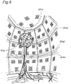
- the microphone array MCa is made up of a C80 fullerrene frame structure of about 46 cm diameter and non-directional microphones (DPA 4060-BM), every one of which is disposed at a node of the frame structure.
- the sound field reproduction environment of a 96-ch speaker system has loudspeakers each of which is built into a cuboid enclosure (Fostex FE103En). Among the loudspeakers, 90 of them are disposed at walls of a room having a 9-sided regular polygonal horizontal section, and 6 of them are disposed at the ceiling of the room.
- a TSP length be 8192 [pnt]
- a TSP response length be 32768 [pnt]
- a sampling frequency be 48000 [Hz]
- a quantization bit rate be 16 [bit].
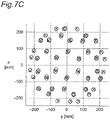
- Figs. 7A , 7B , and 7C show a result of the test. Those figures show the result viewed from straight above, straight in front, and laterally (from a direction rotated horizontally by 90 degrees from the front direction), respectively. In the figures, actual positions of the microphones are denoted by X and position estimation results are denoted by O.
- the object position estimating apparatus is capable of outputting an estimation result with satisfactory accuracy for checking the arrangement of microphones and right or wrong of cable connections.
- Fig. 8 is a graph in which the results are plotted with the horizontal axis of the number of loudspeakers and the vertical axis of the above mentioned error estimation values for estimation results.
- the accuracy of the object position estimation is enhanced monotonically as the number of the loudspeakers (the number of the above mentioned reference points) increases.
- the accuracy of the object position estimation is dramatically enhanced. From this, it can be found that the object position estimation result is obtained with good accuracy when approximately ten or more loudspeakers (above mentioned reference points) are used.
- the object position estimating apparatus is capable of estimating positions of M loudspeakers with the use of N microphones which are arranged at positions corresponding to the N reference points.
- N microphones which are arranged at positions corresponding to the N reference points.
- Fig. 9 is a schematic diagram illustrating relationships among M loudspeakers as target objects of the position estimation, N microphones disposed at positions corresponding to the reference points, and various quantities. For simplicity, only two microphones (MC 1 and MC 2 ) and four loudspeakers (SP 1 ,SP 2 , SP 3 , and SP 4 ) are depicted therein.
- P ij here denotes time (acoustic wave arrival time) when an acoustic wave (TSP wave) emitted from the i-th loudspeaker SP i reaches the j-th microphone (MC j ).
- d SP12 denotes a norm between an N dimensional characteristic vector p SP1 of the first loudspeaker SP i , which includes as its components N acoustic wave arrival time p 1j (j: 1 to N) when the acoustic wave emitted from the first loudspeaker SP 1 arrives at the respective N microphones MC j (j: 1 to N), and an N dimensional characteristic vector p 2j of the second loudspeaker SP 2 , which includes as its components N acoustic wave arrival time p 2j (j: 1 to N) when the acoustic wave emitted from the second loudspeaker SP 2 arrives at the respective N microphones MC j (J: 1 to N).
- d SP23 and d SP34 are a norm between the N dimensional characteristic vector p SP2 of the second loudspeaker SP 2 and an N dimensional characteristic vector p SP3 of a third loudspeaker SP 3 and a norm between the N dimensional characteristic vector p SP3 of the third loudspeaker SP 3 and an N dimensional characteristic vector p SP4 of a fourth loudspeaker SP 4 , respectively.
- the characteristic vector generating unit 4 In the loudspeaker position estimation, the characteristic vector generating unit 4 generates a characteristic vector p SPi (i: 1 to M) for each of the M loudspeakers SP i (i: 1 to M) corresponding to the M position estimation target objects while considering the positions where the microphones MC j (j: 1 to N) are disposed as the above mentioned reference points. And then, a dissimilarity matrix for M loudspeaker positions in the real space is derived from the M characteristic vectors, and the positions in the real space of the loudspeakers are estimated from the dissimilarity matrix.
- the N dimensional characteristic vector p SPi represents characteristics of the position in the real space of the i-th loudspeaker with N dimensional scales, each of which measures closeness to one of the N microphones MC i (i: 1 to N).
- the characteristic vector p SPi is represented as follows:
- P SPi measurement of i - th loudspeaker on a scale measuring closeness to 1st microphone measurement of i - th loudspeaker on a scale measuring closeness to 2nd microphone ⁇ measurement of i - th loudspeaker on a scale measuring closeness to j - th microphone ⁇ measurement of i - th loudspeaker on a scale measuring closeness to N - th microphone P i , 1 P i , 2 ⁇ P i , j ⁇ P i , N ⁇ 1 P i , N .
- the dissimilarity matrix deriving unit 5 (CPU 11) calculates a norm between characteristic vectors of two loudspeakers for every pair of two objects among the M loudspeakers. Then, the dissimilarity matrix deriving unit 5 derives an M-rows and M-columns dissimilarity matrix including the calculated norms as its elements.
- the dissimilarity matrix deriving unit 5 (CPU 11) derives the dissimilarity matrix D based on the N dimensional characteristic vectors p SPi .
- each of the elements d MCkl is expressed as:
- D d SPk , l is a matrix representing a positional dissimilarity of M loudspeakers in the real space, which is obtained through defining a positional dissimilarity of two loudspeakers in the real space in accordance with the N dimensional characteristic vectors p SPi (i: 1 to M) .
- the configuration deriving unit (MDS unit) 6 (CPU 11) applies the MDS to the dissimilarity matrix D to derive a configuration of the M loudspeakers.
- the position estimation result output unit 7 performs an appropriate linear transformation to the configuration matrix X derived by the configuration deriving unit (MDS unit) 6 and so that the actual M microphone positions are determined.
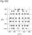
- Figs. 10A , 10B , and 10C show a result of the experimental test. Those figures show the result viewed from straight above, straight in front, and laterally (from a direction rotated horizontally by 90 degrees from the front direction), respectively.
- actual positions of the loudspeakers are denoted by X and position estimation results are denoted by O.
- the second embodiment of the present invention is an object position estimating apparatus, of which portability is improved compared to the first embodiment and, hence, it makes possible to check easily and precisely an arrangement of a microphone array or cable connections at various sound recording scenes.
- Figs. 11 and 12 are block diagrams showing a configuration of an object position estimating apparatus according to the second embodiment.
- the object position estimating apparatus according to the second embodiment may include equivalent components to the apparatus according to the first embodiment, but differs from the object position estimating apparatus according to the first embodiment in that a single external loudspeaker SP (SP 1 ) is connected with an audio output unit 251 included in an audio interface unit 250.
- the loudspeaker SP may be a compact-type loudspeaker with superior portability (audio-technica AT-SPG50, for example).
- a single loudspeaker SP 1 is used to output a predetermined acoustic wave, and, after the output, the loudspeaker SP 1 is moved in order that the loudspeaker SP 1 can emit the acoustic waves at a plurality of positions.
- response waveforms are detected by M microphones MC j (j: 1 to M) respectively so that the acoustic wave arrival time is determined.
- the present embodiment causes the loudspeaker SP 1 to emit the acoustic waves at N positions, and, similarly to the first embodiment, an N dimensional characteristic vector is generated for each of the microphones MC j (j: 1 to M) by means of scales measuring closeness to N reference points.
- the number of loudspeakers is not limited to one. Plural loudspeakers may be used.
- the object position estimating apparatus measures arrival time of a predetermined acoustic wave at each microphone MC j (J: 1 to M) from a single loudspeaker SP i , and, in total, measures the arrival time of the predetermined acoustic wave from N points at each microphone MC j (j: 1 to M).
- the N points here correspond to the above mentioned reference points.
- the characteristic vector generating unit 4 generates a characteristic vector p MCj (j: 1 to M) for each microphone MC j (j: 1 to M) as is the case in the first embodiment.
- the dissimilarity matrix deriving unit 5 derives a dissimilarity matrix D from the generated characteristic vector p MCj (j: 1 to M), and the estimation unit 8 (the configuration deriving unit 6 and the position estimation result output unit 7) estimates and outputs positions in the real space of M microphones from the dissimilarity matrix D.
- the object position estimating apparatus according to the second embodiment shows superior portability compared to the object position estimating apparatus according to the first embodiment since the second embodiment is free from the use of a large-scale speaker array SPa.
- the second embodiment is advantageous in that the microphone position estimation is permitted in a variety of sound recording scenes.
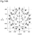
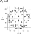
- the present experimental test is conducted at the St. Mary's Cathedral, Tokyo under the circumstance in which an 80-ch microphone array MCa is disposed in the vicinity down from the altar, and a loudspeaker SP 1 (not shown) (audio technica AT-SPG50) is held by hands and carried around over a various positions and an acoustic wave is emitted therefrom.
- the conditions for outputting and detecting an acoustic wave are set such that: a TSP length be 8192 [pnt]; a TSP response length be 105600 [pnt]; a sampling frequency be 48000 [Hz]; and a quantization bit rate be 16 [bit].
- Figs. 14A , 14B , and 14C show a result of the test. Those figures show the result viewed from straight above, straight in front, and laterally (from a direction rotated horizontally by 90 degrees from the front direction), respectively. In the figures, actual positions of the microphones are denoted by X and position estimation results are denoted by O.
- the object position estimating apparatus is capable of outputting an estimation result with satisfactory accuracy for checking the arrangement of microphones and right or wrong of cable connections.
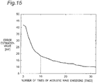
- Fig. 15 is a graph in which the results are plotted with the horizontal axis of the number of acoustic wave emissions and the vertical axis of the above mentioned error estimation values for estimation results. As can be seen on Fig.
- the accuracy of the object position estimation is enhanced monotonically as the number of the acoustic wave emissions used for the object position estimation (the number of the above mentioned reference points) increases. Especially, while the number of the loudspeakers does not exceed 10, the accuracy of the object position estimation is dramatically enhanced. From this, it can be found that, according to the object position estimation of the present embodiment, the object position estimation result is obtained with good accuracy even in the sound recording scene where a content is actually being created when the number of acoustic wave emissions (that is, the above mentioned reference points) is made approximately ten or more.
- Variation 1 concerns another approach to generating a characteristic vector.
- Variation 2 concerns another approach to estimating configuration of objects from a dissimilarity matrix.
- the Variation 1 and Variation 2 are applicable to the object position estimating apparatus according to the first and second embodiments independently from each other and simultaneously.
- a characteristic vector is generated based on the time (acoustic wave arrival time) when an acoustic wave that has been emitted from a loudspeaker located on a reference point arrives at a microphone.
- the characteristic vector is generated based on amplitude-frequency characteristics of an output signal outputted from the microphone.
- Fig. 16 is a block diagram showing a configuration of a variation of the object position estimating apparatus. It is to be noted that constituent elements similar to those depicted in Fig. 1 etc. are depicted with similar reference numerals and descriptions thereof are omitted.
- the variation of the object position estimating apparatus has a configuration, in which a timer 41 and an audio output unit 51 are omitted from the configuration of the object position estimating apparatus depicted in Fig. 1 .
- the present apparatus does not have to be connected with a speaker array SPa which is composed of external loudspeakers (SP 1 , SP 2 , ..., SP N ).
- Fig. 17 is a block diagram explicitly illustrating functional blocks realized by the computer main components 10 of the object position estimating apparatus 300.
- the CPU 11 of the computer main components 10 reads out and executes an object position estimation program stored in the ROM 12 so that the CPU 11 is capable of operating as a controller 1, an amplitude-freguency characteristics calculating unit 303, a characteristic vector generating unit 304, a dissimilarity matrix deriving unit 5, a configuration deriving unit (MDS unit) 6, and a position estimation result output unit 7.
- the configuration deriving unit (MDS unit) 6 and the position estimation result output unit 7 constitute an estimation unit 8.
- the operations by the controller 1, the dissimilarity matrix deriving unit 5, the configuration deriving unit (MDS unit) 6, and the estimation unit 8 may be the same as those described in the first and second embodiments and, hence, descriptions thereof are omitted here.
- the amplitude-freguency characteristics calculating unit 303 is realized when the CPU 11 executes the object position estimation program.
- the amplitude-frequency characteristics calculating unit 303 calculates amplitude-frequency characteristics of an output signal of each microphone (MC 1 to MC M ) included in the microphone array MCa.
- the characteristic vector generating unit 304 is realized when the CPU 11 executes the object position estimation program.
- the characteristic vector generating unit 304 inputs the amplitude-frequency characteristics calculated by the amplitude-frequency characteristics calculating unit 303 and generates an N dimensional characteristic vector for each of the M microphones (objects).
- the characteristic vector generating unit 304 obtains a difference of corresponding components of characteristic vectors of every two microphones among M microphones (objects) (difference between components of characteristic vectors of equation (1) p i,j - p i,k k: k ⁇ j, i: an arbitrary integer from 1 to N) based on the amplitude-frequency characteristics.
- a person skilled in the art will know from the descriptions below a technique for determining components themselves of a characteristic vector of each microphone.
- At least one of the controller 1, the amplitude-frequency characteristics calculating unit 303, the characteristic vector generating unit 4, the configuration deriving unit (MDS unit) 6, and the position estimation result output unit 7 may be implemented with a dedicated hardware circuitry.
- Fig. 18 is a schematic diagram illustrating a situation where three humans hmn1 - hmn3 are having a meeting in a room.
- M microphones MC 1 to MC M
- the M microphones (MC 1 to MC M ) are connected to the object position estimating apparatus 300 not shown via the audio interface unit 350 not shown (see Fig. 17 ).
- Fig. 19 is a flowchart of processes for the microphone position estimation performed by the object position estimating apparatus 300.
- the amplitude-freguency characteristics calculating unit 303 of the object position estimating apparatus 300 inputs output signals from the M microphones (MC 1 to MC M ) through the audio interface unit 350. These output signals correspond to response signals of the M microphones with respect to an ambient sound in the room.
- the amplitude-frequency characteristics calculating unit 303 extracts a portion in which a human voice is included in the ambient sound (for example, the portion including the voice "Hi! by the speaker hmn1 in Fig. 18 ) from each of the output signals, and transforms the extracted output signals (time domain) of the M microphones (MC 1 to MC M ) into the frequency domain to calculate their amplitude-frequency characteristics of the output signals (frequency domain) (step S101).
- Information about the amplitude-frequency characteristics of the output signals of microphones (MC 1 to MC M ) are transferred to the characteristic vector generating unit 304 from the amplitude-frequency characteristics calculating unit 303.
- the characteristic vector generating unit 304 calculates a difference between the amplitude-frequency characteristics of the output signals for every pair of two microphones (MC j , MC k ) based on the information about the amplitude-frequency characteristics transferred from the amplitude-frequency characteristics calculating unit 303 (step S102).
- the characteristic vector generating unit 304 Based on an integral value that is obtained through integrating the calculated difference between two amplitude-frequency characteristics along the frequency axis, the characteristic vector generating unit 304 obtains a dissimilarity between positions of two microphones with respect to a speaker (reference point). Namely, the characteristic vector generating unit 304 obtains, based on the integral value, a difference (corresponding to p i,j -p i,k in equation (1), k ⁇ j, i: an arbitrary integer from 1 to N) between measurements of the two microphones on the scale defining closeness to the reference point.
- a difference corresponding to p i,j -p i,k in equation (1), k ⁇ j, i: an arbitrary integer from 1 to N
- Fig. 20 is a schematic diagram illustrating amplitude-frequency characteristics of output signals of respective microphones (MC 1 to MC M ).
- Fig. 20(a) is amplitude-frequency characteristics of an output signal from a microphone MC 1 regarding an ambient sound in a room illustrated in Fig. 18 , which includes a human voice spoken by a human hmn1.
- Fig. 20(b) and Fig. 20(c) are amplitude-frequency characteristics of output signals from microphones MC j and MC M regarding the same ambient sound including the same voice, respectively.
- a central frequency of the first formant F1 is denoted by f1
- central frequencies of the second and higher formants are denoted by f2, f3, f4, respectively.
- the characteristic vector generating unit 304 is capable of determining a difference of closeness to a speaker (reference point) between two microphones from the difference of shapes of the amplitude-frequency characteristics of the output signals of the two microphones.
- the characteristic vector generating unit 304 integrates a difference of amplitude-frequency characteristics of output signals from two microphones (MC j , MC k , k: k ⁇ j) along the frequency axis (step S103).
- the integral value obtained here corresponds to a difference between the microphone MC j and the microphone MC k with respect to closeness to a reference point (speaker).
- the integral value obtained here corresponds to a difference of components regarding the reference point in the characteristic vectors of the two microphones (MC j , MC k ) (p i,j - p i,k in equation (1), k ⁇ j, i: an arbitrary integer from 1 to N).
- the characteristic vector generating unit 304 is capable of determining the components themselves of each characteristic vector from the thus determined difference between the components related to the speaker (reference point) in the characteristic vectors of the two microphones.
- the characteristic vector generating unit 304 obtains a dissimilarity of positions of two microphones with respect to each reference point (a difference between corresponding components of characteristic vectors) for every pair of two microphones (MC 1 to MC M ) in step S103.
- step S104 the dissimilarity matrix deriving unit 5 derives a dissimilarity matrix D (equation (3)) based on the differences between corresponding components of every pair of two characteristic vectors, which are determined by the characteristic vector generating unit 304.
- the characteristic vector generating unit 304 may obtain a characteristic vector of each microphone from the integral value obtained in step S103 and output the same to the dissimilarity matrix deriving unit 5.
- the dissimilarity matrix deriving unit 5 may derive the dissimilarity matrix in step S104 in a similar way to step S7 in the previous embodiments.
- step S105 and step S106 may be identical to those described in the previous embodiments (step S8 and step S9 in Fig. 4 ) and, hence, the descriptions thereto are omitted here.
- the object position estimating apparatus collects voices spoken by a speaker(s) at N points of positions (N being three or more) which differ from each other by means of M microphones and derives a dissimilarity matrix D with the use of output signals, which have been collected and outputted by the respective microphones (step S104).
- N being three or more
- the human who speaks at the N points of positions does not have to be the same person.
- the characteristic vector generating unit 304 may generate a characteristic vector based on the information about the amplitude-freguency characteristics transferred from the amplitude-frequency characteristics calculating unit 303 in the way described below. Firstly, the characteristic vector generating unit 304 identifies formants of a speaker in the output signals from the microphones (MC 1 to MC M ). In the identification, the characteristic vector generating unit 304 may determine the amplitudes of the identified formants (the first formants F1, for example).
- the characteristic vector generating unit 304 may determine a measurement on a scale measuring closeness to a reference point (human hmn1) for each microphone (MC 1 to MC M ) from a ratio (in units of dB, for example,) of a peak amplitude of a specific formant (first formant F1 having a central frequency of f1, for example,) appearing on the amplitude-frequency characteristics of an output signal from each microphone (MC 1 to MC M ) to a peak amplitude (an amplitude A1f1 in Fig. 20(a) ) of the specific formant appearing on the amplitude-frequency characteristics of an output signal from one arbitrary microphone (MC1, for example).
- first formant F1 having a central frequency of f1, for example
- the measurement for the microphone MC 1 on a scale measuring closeness to a human hmn1 as a reference point may be defined as 1 and the measurement for the microphone MC M on the scale measuring closeness to the reference point (human hmn1) may be evaluated as 2, for example.
- the characteristic vector generating unit 304 is capable of determining a characteristic vector of each microphone (MC 1 to MC M ) based on the specific frequency component in the amplitude-frequency characteristics.
- the object position estimating apparatus 300 does not have to emit a particular acoustic wave.
- the present variation is especially beneficial to the object position estimation in a room having an acoustic property under which enriched reverberant sounds can be produced or in a bustle.
- an estimation unit 8 having a configuration deriving unit 6 estimates the configuration of objects by applying the MDS method to the dissimilarity matrix.
- the configuration deriving unit 6 may obtain (an approximate solution of) the configuration by numerically solving a so-called combinatorial optimization problem by means of a full search technique.
- the configuration deriving unit 6 may evaluate, for every possible configurations (configuration approximate solution candidates) of objects (M microphones, for example), a suitability for a configuration approximate solution based on the dissimilarity matrix, and output the configuration approximate solution candidate that has been most highly evaluated as the configuration estimation result.
- the configuration deriving unit 6 may obtain (an approximate solution of) the configuration by solving numerically a so-called combinatorial optimization problem by means of a local search technique with the aid of an algorithm such as a so-called genetic algorithm, for example.
- the configuration deriving unit 6 may evaluate, for some possible configurations (configuration approximate solution candidates) of objects (M microphones, for example), a suitability for a configuration approximate solution based on the dissimilarity matrix, and output the configuration approximate solution candidate that has been most highly evaluated as the configuration estimation result.
- This technique is especially effective when the configuration approximate solution is numerically solved in accordance with a dissimilarity matrix by means of a full-search or a local-search technique.
- the number of possible configuration approximate solution candidates is reduced so that the configuration approximate solution derivation can be accelerated. Further, by confining a spatial range where the object can exist using information about a distance between an arbitrary one reference point and the object which is closest to the one reference point and a distance between the one reference point and the object which is most distant from the one reference point, the number of configuration approximate solution candidates can be drastically reduced.
- the time when an acoustic wave emitted from a loudspeaker disposed at a reference point arrives at each microphone is specified to generate a characteristic vector.
- the time when the acoustic wave is emitted by a loudspeaker disposed at a reference point may be additionally specified so that the amount of time required for the acoustic wave to arrive at each microphone (acoustic wave travel time) can be obtained.
- the microphone that has marked the shortest acoustic wave travel time is the microphone closest to the certain reference point
- the microphone that has marked the longest acoustic wave travel time is the microphone most distant from the certain reference point.
- a minimum distance R min and a maximum distance R max be a product of the shortest acoustic wave travel time and the speed of sound and a product of the longest acoustic wave travel time and the speed of sound, respectively.
- Fig. 21 is a diagram illustrating object position candidates CD (x in the figure) in the case where the minimum distance of objects d min , the shortest distance to a certain reference point R min , and the longest distance from the certain reference point R max are provided as the condition on possible positions of position estimation target objects.
- the object position candidates CD are distributed at intervals of the minimum distance d min within a range outside a sphere sph1 of radius R min centered at a certain reference point (loudspeaker in the figure) and inside a sphere sph2 of radius R max centered at the same reference point.
- the configuration deriving unit 6 Fig.
- the configuration deriving unit 6 may evaluate a suitability for a configuration approximate solution of each configuration approximate solution candidate that consists of candidates corresponding to the number of the objects (M candidates) chosen from the object position candidates CD based on a dissimilarity matrix. Then, the configuration deriving unit 6 may consider the configuration approximate solution candidate which has deserved a good evaluation as a configuration approximate solution. In the case where the full-search technique is employed, the suitability of all possible configuration approximate solution candidates may be evaluated. In the case where the local-search technique is employed, configuration approximate solution candidates to be evaluated may be selected according to well-known algorithms (genetic algorithm, etc.).
- the suitability evaluation may be performed as follows. First, a distance between objects in a configuration approximate solution candidate to be evaluated is calculated and, based on the calculation result, a distance matrix of which elements are the distance between the objects is derived. Then, it is possible to evaluate the suitability by estimating a degree of similitude between the calculated distance matrix and a dissimilarity matrix. In short, it is possible to evaluate the suitability of a configuration approximate solution candidate by more highly rating a distance matrix of which relationship with the dissimilarity matrix approaches more closely to a proportional relationship.
- Fig. 22 is a diagram illustrating object position candidates CD (x in the figure), in which a further condition that the microphones as the objects should constitute a linear shape microphone array is added.
- the object position candidates CD are distributed only on a straight line L that touches the sphere sph1 at the candidate CD near .
- the microphone that has marked the shortest acoustic wave travel time and the microphone that has marked the longest acoustic wave travel time be located on the candidate CD near and a candidate CD far on a surface of the sphere sph2, respectively.
- a configuration approximate solution candidate including such an arrangement and performing a local-search thereto.
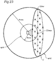
- Fig. 23 is a diagram illustrating object position candidates CD (x in the figure), in which a further condition that the microphones as the objects should constitute a planar shape microphone array is added.
- the object position candidates CD are distributed only on a circle C that touches the sphere sph1 at the candidate CD near .
- the microphone that has marked the shortest acoustic wave travel time and the microphone that has marked the longest acoustic wave travel time be located on the candidate CD near and a candidate CD far on a surface of the sphere sph2, respectively. Accordingly, it is possible to accelerate the derivation of a configuration approximate solution by selecting a configuration approximate solution candidate including such an arrangement and performing a local-search thereto.
- Fig. 24 is a diagram illustrating object position candidates CD (x in the figure), in which a further condition that the microphones as the objects should constitute a regular square shape microphone array is added.
- the object position candidates CD are distributed only on a regular square SQ that is inscribed in a circle C which touches the sphere sph1 at the candidate CD near .
- the microphone that has marked the shortest acoustic wave travel time and the microphone that has marked the longest acoustic wave travel time be located on the candidate CD near and a candidate CD far on a surface of the sphere sph2, respectively. Accordingly, it is possible to accelerate the derivation of a configuration approximate solution by selecting a configuration approximate solution candidate including such an arrangement and performing a local-search thereto.
- Fig. 25 is a diagram illustrating object position candidates CD (x in the figure), in which a further condition that the microphones as the objects should constitute a spherical-surface shape microphone array is added.
- the object position candidates CD are distributed only on a surface of a sphere sph3 that touches the sphere sph1 externally at the candidate CD near and touches the sphere sph2 internally at the candidate CD far .
- the microphone that has marked the shortest acoustic wave travel time and the microphone that has marked the longest acoustic wave travel time be located on the candidate CD near and the candidate CD far , respectively. Accordingly, it is possible to accelerate the derivation of a configuration approximate solution by selecting a configuration approximate solution candidate including such an arrangement and performing a local-search thereto.
- the object position estimating apparatuses according to the embodiments of the present invention are capable of estimating the object positions without measuring a distance between position estimation target objects.
- the object position estimating apparatuses according to the embodiments of the present invention obtains measurements regarding intervals in the real space between each object and N reference points (N: an integer more than or equal to 3), which are able to be selected arbitrarily and independently from the positions of the objects, instead of the utilization of the distance between position estimation target objects. Then, the apparatuses generate an N dimensional characteristic vector indicating positional property of the object in the real space based on the obtained measurements, derive a dissimilarity matrix from the characteristic vectors, and derive a configuration of the objects in the (three-dimensional) real space from the dissimilarity matrix.
- the embodiments of the present invention it is not necessary to measure the distances between the position estimation target objects. This makes it possible to easily estimate positions of the objects with accuracy in various situations. Furthermore, in the embodiments of the present invention, by increasing the number of the N reference points (N: an integer more than or equal to 3) selectable arbitrarily and independently from the positions of the objects, the number of dimensions of the characteristic vector indicating the positional property of each object in the real space can be increased.
- the embodiments of the present invention are useful as an apparatus for easily and accurately checking an arrangement of microphones and cable connections in a multichannel sound recording system, for example.
- the embodiments of the present invention are useful as an apparatus for easily and accurately checking an arrangement of loudspeakers and cable connections in a multichannel sound field reproduction system, for example.
- the embodiments of the present invention are capable of estimating positions of a plurality of laptop PCs by means of a microphone and a loudspeaker built-into a laptop PC.
- the embodiments of the present invention can also be used as an apparatus for easily and accurately checking an arrangement of microphones of a microphone array for voice-recognition and cable connections.
- the components of the characteristic vector indicating the positional property of an object in the real space are generated as time of the arrival of an acoustic wave from a predetermined reference point. That is, in the embodiments, respective components of the characteristic vector are quantities having temporal dimension.
- the characteristic vector can be constructed using observed quantities having various dimensions other than the temporal dimension.
- the characteristic vector can be constructed using quantities on which a shape of reverberant components of a response waveform detected by a microphone is reflected. Namely, the characteristic vector can be constructed based on quantities indicating relative relationship between a direct sound and a reverberant sound within a response waveform.
- the dissimilarity matrix may be constructed with data which indicate (dis-)similarity between response waveforms respectively detected by two microphones included as its elements.
- the object position estimating apparatus may obtain cross-correlation of respective elements in the dissimilarity matrix, and, based on the obtained cross-correlation, estimate positions of the position estimation target objects in the real space.
- the object position estimating apparatus may collect an ambient sound in which a human voice is included by means of M microphones, and based on the amplitude-frequency characteristics of output signals outputted by the respective microphones, generate the characteristic vector.
- the characteristic vector By comparing shapes of the amplitude-frequency characteristics of the output signals from a plurality of microphones (by integrating a difference between the amplitude-frequency characteristics along the frequency axis, for example), it is possible to quantify a relative difference of closeness to a speaker from a plurality of microphones.
- components of the characteristic vector may be determined based on a ratio of amplitudes of a specific frequency components (a frequency where a format of a human voice appears) in the amplitude-frequency characteristics of the output signals outputted by respective microphones, for example.
- the object position estimating apparatus is capable of determining a component of the characteristic vector by evaluating in a relative manner among the M microphones the closeness between the human who produced a voice and the microphone which has outputted an output signal on the basis of an amplitude of a formant of the human voice extracted from the amplitude-frequency characteristics of the output signal.
- An approach like this for generating a characteristic vector is beneficial to the position estimation in a room having a rich reverberation property or in a bustle.
- the object position estimating apparatuses may estimate the object position using a wave such as light or an electromagnetic wave instead of an acoustic wave.
- the object position estimating apparatus may include a light-emitting element array and a photo-sensitive element array or two sets of antenna-arrays, for example.
- the apparatus as such can estimate positions of the light-emitting element array (or the photo-sensitive element array or one set of the antenna-array) by detecting wave motions from the light-emitting element array (or the one set of the antenna-arrays) by means of the photo-sensitive element array (or the other set of the antenna-array).
- the object position estimating apparatuses may estimate the object position using a surface-wave propagating over a surface of matter instead of an acoustic wave.
- the object position estimating apparatus may include two sets of transducer arrays which convert electrical energy to vibrational energy, for example. The apparatus as such can estimate positions of one set of the transducer array by detecting surface waves from the one set of the transducer array by means of the other set of the transducer array.
- the embodiments of the present invention can be used for checking positions of a plurality of microphones and cable connections at the site of sound recording, for example.
- the estimation unit of the object position estimating apparatus may seek an approximate solution of the configuration numerically by means of a full-search or a local-search technique instead of applying the MDS method to an dissimilarity matrix, and estimate the positions in the real space of the M microphones from the configuration approximate solution.
Description
- The present invention relates to an object position estimating apparatus, and particularly to the object position estimating apparatus which estimates positions of a plurality of objects.
- Recently, a system utilizing a multichannel sound field recording and reproduction system has come under the spotlight. The system provides a vivid presence sound field. A variety of systems such as: a 2ch stereo-sound system; a binaural system; a 5.1ch surround-sound system, each of which uses relatively few channels, and; a 22.2 multichannel sound system; and a 121ch microphone array / 157ch loudspeaker array system using advanced technology developed from the principle of Ambisonics, each of which uses relatively many channels, has already been proposed.
- When recording a sound field with the system mentioned above, one has to check an arrangement of tens of microphones and cable-connections between the microphones and a sound recording device at the site of recording. By the same token, when reproducing a sound field with the system mentioned above, one also have to check the arrangement of tens of loudspeakers and cable-connections between the loudspeakers and a sound reproduction device at the site of reproduction.
- Accordingly, an apparatus with which one can easily check the arrangement of a number of microphones (or a number of loudspeakers) and cable-connections is anticipated.
- Patent Literature 1 (
US2010/0195444A Specification) discloses a method for estimating positions of a plurality of loudspeakers. In the method ofPatent Literature 1, with respect to the plurality of loudspeakers regarded as position estimation objects, distances of every pairs among the loudspeakers are measured. Based on the measurement result, a distance matrix of which each element shows a distance of a loudspeaker pair in a real space is derived. In the method ofPatent Literature 1, then, the Multidimensional Scaling is applied to the distance matrix derived as mentioned above to obtain the positions in the real space of the plurality of the loud speakers.US20020167862 discloses a technique for approximating a source position of a source causing event, wherein a plurality of source-detecting devices are configured to detect sound from an event of interest. - PTL 1:
US2010/0195444A1 Specification PTL 2:US 2002/0167862 A1 Specification -
- NPL 1: Vikas C. Raykar, Igor Kozintsev and Rainer Lienhart, Position Calibration of Microphones and Loudspeakers in Distributed Computing Platforms, IEEE Transactions On Speech And Audio Processing, p.1-12.
- NPL 2: Stanley T. Birchfield, Amarnag Subramanya, Microphone Array Position Calibration by Basis-Point Classical Multidimensional Scaling, IEEE Transactions On Speech And Audio Processing, Vol. 13, No. 5, September 2005, p. 1025-1034.
- NPL 3: Alessandro Redondi, Marco Tagliasacchi, Fabio Antonacci, Augusto Sarti, Geometric calibration of distributed microphone arrays, MMSP'09, October 5-7, 2009, Rio de Janeiro, Brazil, IEEE.
- NPL 4: Kazunori Kobayashi, Ken'ichi Furuya, Akitoshi Kataoka, A Blind Source Localization by Using Freely Positioned Microphones, Institute of Electronics, Information, and Communication Engineers, The Transactions of the Institute of Electronics, Information and Communication Engineers A, Vol. J86-A, No. 6, p. 619-627.
- In the conventional art, however, distances in the real space of all pairs of position estimation objects (all pairs of a plurality of loudspeakers in
Patent Literature 1, for example,) are measured, and then, based on the measurement result, a distance matrix is derived. The distance matrix has elements each of which is the distance in the real space between the paired loudspeakers. The Multidimensional Scaling is applied to the distance matrix derived as mentioned above, equated with a matrix of position estimation object's (dis-)similarity, so that the positions in the real space of the plurality of the loudspeakers are obtained. The number of distances to be measured increases as the number of the position estimation objects increases. For this, it makes hard to estimate the positions. Further, the possibility of an estimation error due to a measurement error will grow as the number of the position estimation objects increases. Furthermore, in certain cases, it is not as easy to measure the distances between the position estimation objects precisely in certain cases not as in the case described inPatent Literature 1. The conventional art has failed to provide easy-and-precise object position estimation. - Considering the problems mentioned above, each embodiment of the present invention provides an apparatus that estimates positions in the real space of a plurality of objects easier and more precisely than the conventional art.
- First aspect of the present invention is an object position estimating apparatus which estimates positions of M objects (M being an integer greater than or equal to 2) in a real space, as set forth in the appended claims.
- Second aspect of the present invention is an object position estimation method for estimating positions of M objects (M being an integer greater than or equal to 2) in a real space by an object position estimating apparatus which estimates the positions of the objects, as set forth in the appended claims.
- Third aspect of the present invention is an object position estimation program which causes an computer that is configured to operate an object position estimating apparatus according to
claim 1 to perform functions of the object position estimating apparatus which estimates positions of M objects (M being an integer greater than or equal to 2) in a real space, as set forth in the appended claims. - The object position estimating apparatus according to embodiments of the present invention: generates, for each of the M objects, a characteristic vector including measurements of the object measured on N scales (N: an integer greater than or equal to 3) as its components, each of the N scales measuring closeness to each of N reference points in the real space; calculates a norm between the characteristic vectors of two objects for every pair from among the M objects to derive a dissimilarity matrix with M rows and M columns, the dissimilarity matrix including as elements the calculated norms; and estimates the positions of the M objects in the real space on the basis of the dissimilarity matrix and outputs a estimation result. In this manner, the object position estimating apparatus is capable of estimating positions of objects more easily and accurately than ever before.
-
-
Fig. 1 is a block diagram of a hardware configuration of an object position estimating apparatus according to a first embodiment. -
Fig. 2 is a diagram of a configuration of the object position estimating apparatus according to the first embodiment. -
Fig. 3 is a schematic diagram illustrating a relationship among quantities used for microphone position estimation. -
Fig. 4 is a flow chart of process performed by the object position estimating apparatus. -
Fig. 5 is a diagram illustrating difference among time at which microphones pick up a time stretched pulse signal (TSP signal) emitted from an i-th loudspeaker. -
Fig. 6 is a diagram showing experimental environments of a microphone position estimation experiment and a loudspeaker position estimation experiment with the first embodiment. -
Fig. 7A is a diagram showing a result of the microphone position estimation with the first embodiment. -
Fig. 7B is a diagram showing a result of the microphone position estimation with the first embodiment. -
Fig. 7C is a diagram showing a result of the microphone position estimation with the first embodiment. -
Fig. 8 is a diagram showing a relationship between accuracy of the estimation results and the number of loudspeakers used at the microphone position estimation with the first embodiment. -
Fig. 9 is a schematic diagram illustrating a relationship among quantities used for loudspeaker position estimation. -
Fig. 10A is a diagram showing a result of the loudspeaker position estimation with the first embodiment. -
Fig. 10B is a diagram showing a result of the loudspeaker position estimation with the first embodiment. -
Fig. 10C is a diagram showing a result of the loudspeaker position estimation with the first embodiment. -
Fig. 11 is a block diagram of a hardware configuration of an object position estimating apparatus according to a second embodiment. -
Fig. 12 is a diagram of a configuration of the object position estimating apparatus according to the second embodiment. -
Fig. 13 is a diagram showing an experimental environment of a microphone position estimation experiment with the second embodiment. -
Fig. 14A is a diagram showing a result of the microphone position estimation with the second embodiment. -
Fig. 14B is a diagram showing a result of the microphone position estimation with the second embodiment. -
Fig. 14C is a diagram showing a result of the microphone position estimation with the second embodiment. -
Fig. 15 is a diagram of a relationship between accuracy of the estimation results and the number of times of sound-emissions by a loudspeaker in the microphone position estimation with the second embodiment. -
Fig. 16 is a block diagram of a hardware configuration of an object position estimating apparatus according to avariation 1. -
Fig. 17 is a diagram of a configuration of the object position estimating apparatus according to thevariation 1. -
Fig. 18 is a schematic diagram illustrating a relationship between a group of microphones arranged in a room and peoples. -
Fig. 19 is a flow chart of process performed by the object position estimating apparatus according to thevariation 1. -
Fig. 20 is a diagram of an example of amplitude-frequency characteristics of a microphone output signal outputted from each of microphones during each of the microphones collects sound in which human voice is included. -
Fig. 21 is a diagram of an example of a distribution of the object position candidates according to avariation 2 of the object position estimating apparatus. -
Fig. 22 is a diagram of an example of a distribution of the object position candidates according to thevariation 2 of the object position estimating apparatus. -
Fig. 23 is a diagram of an example of a distribution of the object position candidates according to thevariation 2 of the object position estimating apparatus. -
Fig. 24 is a diagram of an example of a distribution of the object position candidates according to thevariation 2 of the object position estimating apparatus. -
Fig. 25 is a diagram of an example of a distribution of the object position candidates according to thevariation 2 of the object position estimating apparatus. - Embodiments according to the present invention are described below with reference to the accompanying drawings.
- The embodiment of the present invention is an object position estimating apparatus which estimates positions of M objects in a real space (where the M is an integer greater than or equal to 2). It is the one of the features of the object position estimating apparatus that the apparatus includes:
- a characteristic vector generating unit which generates, for each of the M objects, a characteristic vector, the characteristic vector including as components measurements of the object measured on N scales, each of the N scales measuring closeness to each of N reference points in the real space (where the N is an integer greater than or equal to 3);
- a dissimilarity matrix deriving unit which calculates a norm between the characteristic vectors of two objects for every pair from among the M objects and derives a dissimilarity matrix with M rows and M columns, the dissimilarity matrix including as elements the calculated norms; and
- an estimation unit which estimates the positions of the M objects in the real space on the basis of the dissimilarity matrix and outputs an estimation result.
- In this context, the M objects may be M microphones, for example. (the M may be an integer greater than or equal to 2 as mentioned above.)
- In such the case, N loudspeakers are arranged in a space for estimating the positions of the M microphones. (the N may be an integer greater than or equal to 3 as mentioned above.) The positions at which the N loudspeakers are disposed correspond to the above mentioned reference points, respectively.
- The object position estimating apparatus causes the loudspeaker to emit a predetermined acoustic wave (by outputting a time stretched pulse signal (TSP signal) to the loudspeakers for measuring an impulse response of a microphone, for example); and determines time (acoustic wave arrival time) at which the acoustic wave having been emitted from the loudspeaker firstly arrives at each of the microphones. For example, the apparatus specifies the time at which a waveform corresponding to the acoustic wave (an impulse response waveform, for example,) firstly appears in an output from the microphone. In this case, the N scales which measure closeness to each of the N reference points are the time coordinate axes each used in the determination of the acoustic wave arrival time from each of the loudspeakers, and the measurements of the object are the acoustic wave arrival time at each of the microphones.
- Then, based on the acoustic wave arrival time specified, the characteristic vector generating unit generates, for each microphone (object), a vector of N dimensions (a characteristic vector) which includes, as its components, the time when acoustic waves from N reference points have arrived. The characteristic vector generating unit generates the characteristic vector of N dimension, in which the N is same as the number of reference points, while considering the times when the acoustic waves emitted from reference points have reached the microphone as the measurements on the scales (the time axis as mentioned above) which measure the closeness to the reference points from the microphone in the real space. In short, the characteristic vector is a vectorial representation of characteristics of the microphone's position in the real space, in which the characteristics are represented with the measurements (acoustic wave arrival time) on N scales (time axes) that measure closeness to N reference points (loudspeakers) from the microphone in the real space.
- Alternatively, the object position estimating apparatus may collect ambient sounds, in which a human voice is involved, using M microphones and calculate amplitude-frequency characteristics of an output signal from each of the microphones to generate the characteristic vector. In the approach just mentioned above, there is no need to cause the loudspeakers, which are disposed at N reference points as mentioned, to emit the predetermined acoustic waves. In the amplitude-frequency characteristics of the ambient sounds that involve a human voice, formants of the human voice appear therein. The formants are superposed on the components of ubiquitous noise from the recording environment (such as reverberant sound in a room, hustle and bustle sounds in outdoors, etc.). As the microphone position recedes from the speaker, the shape of the formant in the amplitude-frequency characteristics deviates from its original shape due to the increase of the effects from the noise. Accordingly, it is possible to determine the relative closeness between the speaker and each of the plural microphones by comparing the shapes of the amplitude-frequency characteristics of output signals from the microphones. For example, a value of integral of a difference between amplitude-frequency characteristics of output signals from two microphones along the frequency axis may be used as the difference between the measurements for the two microphones on the scale that defines closeness to the speaker (the dissimilarity with respect to the speaker). Because, even if the positions of the two microphones differ from each other, amplitude components originated from the noise appearing in the amplitude-frequency characteristics of output signals have little difference from each other. Accordingly, the amplitude components originated from noise can be cancelled by taking the difference between the amplitude-frequency characteristics. Consequently, the difference between the amplitude-frequency characteristics involves information about the difference of closeness to the speaker. It is to be understood that the object position estimating apparatus is also capable of determining the measurement for each microphone on the scale defining closeness to the speaker (components regarding the speaker of the characteristic vector) based on the thus obtained difference of the amplitude-frequency characteristics for any two microphones.
- On the other hand, it is known that an amplitude of a formant appearing in the amplitude-frequency characteristics decreases about 6 decibels if a distance between a speaker and a microphone increases twice, for example. Base on this relationship, the characteristic vector generating unit of the object position estimating apparatus may determine the components of the characteristic vector by identifying formant components of a speaker from an amplitude-frequency characteristic of an output signal of each microphone and deriving the measurement for each microphone representing closeness to the speaker position (corresponding to a reference point) with the use of the magnitude of the amplitude of the identified formant as the measurement. As mentioned above, three or more reference points are required. Accordingly, the object position estimating apparatus collects voices produced by a speaker(s) at different N points (N is greater than or equal to three) by means of the M microphones and generates the characteristic vector of N dimensions.
- Then, the dissimilarity matrix deriving unit calculates a norm between the characteristic vectors for every pair from the M microphones and derives a matrix with M rows and M columns (a dissimilarity matrix) which includes the calculated norms as its elements.
- Next and finally, the estimation unit estimates the positions of the M microphones in the real space based on the dissimilarity matrix and outputs an estimation result. The estimation unit applies the MultiDimensional Scaling method (MDS) to the dissimilarity matrix to obtain a configuration of M microphones, and estimates and outputs the position of the M microphones in the real space from the obtained configuration.
- Alternatively, the estimation unit of the object position estimating apparatus may numerically obtain an approximate solution of the configuration using full-search or local-search technique, and may estimate and output the positions of M microphones in the real space from the obtained configuration approximate solution. In this case, the estimation unit derives, for each of approximate solution candidates of the M microphones configuration, a distance matrix, each of which elements is a distance between microphones. The estimation unit compares the derived distance matrix with the dissimilarity matrix to evaluate a suitability of the approximate solution candidate and determines the approximate solution candidate that shows highest suitability among the evaluated approximate solution candidates as the approximate solution of the configuration.
- In the M objects position estimation by the object position estimating apparatus according to the embodiment of the present invention, the positions of the above mentioned N reference points may be arbitrary N points, and information about the positions of the reference points in the real space (coordinate values of the reference points in the real space, for example) is not necessary. Accordingly, the object position estimating apparatus is capable of estimating positions of M objects without measuring a distance between a pair of position estimation target objects. For this, it is possible to estimate the positions of M objects in a very simple way. In addition, in the object position estimation according to the present invention, the characteristics of the object's position in the real space is firstly specified as a vector of N dimensions (the characteristic vector), which is identical to the number of reference points N (the number of loudspeakers, for example), and then, the dissimilarity with respect to the positions in the real space of the objects is derived from the thus generated N dimensional characteristic vector. For this, in the object position estimation according to the embodiment of the present invention, accuracy of the position estimation for M objects is improved as the number of the reference points (N) increases.
- It is to be noted that the object position estimating apparatus according to the embodiment of the present invention requires loudspeakers to emit predetermined acoustic waves at the positions corresponding to the N reference points in order to generate the characteristic vectors for M microphones corresponding to the M position estimation target objects but this does not mean N loudspeaker units should necessarily be prepared. In the object position estimating apparatus according to the embodiment of the present invention, loudspeaker units less than N (one loudspeaker unit, for example,) may be used to emit the predetermined acoustic waves at N positions.
- Instead of the microphones, the M objects may be M loudspeakers (M may be an integer greater than or equal to 2 as mentioned above). In this case, N microphones are disposed and the characteristic vectors are generated while considering the positions where the respective microphones are disposed as the above mentioned reference points. Then the dissimilarity matrix for the M loudspeakers is derived from the M characteristic vectors and positions of the loudspeakers in the real space can be estimated from the dissimilarity matrix.
- A person skilled in the art will comprehend the details of the method for estimating positions of M objects in the real space (where the M is an integer greater than or equal to 2) in the object position estimating apparatus which estimates the positions of objects in the real space from the descriptions about the object position estimating apparatus according to the embodiment of the present invention.
- In addition, the person skilled in the art will comprehend the configuration of a computer program for causing a computer to operate as the object position estimating apparatus which estimates positions of M objects in the real space (where the M is an integer greater than or equal to 2) from the descriptions below.
-
Fig. 1 is a block diagram showing a configuration of an object position estimating apparatus according to the first embodiment. The object position estimating apparatus includes: a central processing unit (CPU) 11 which executes a program and performs a predetermined data processing; a read only memory (ROM) 12 which stores the program; a random access memory (RAM) 13 which stores a variety of data; a hard disk drive (HDD) 21 which functions as an auxiliary storage device; adisplay 31 which operates as an output device; akeyboard 32 and amouse 33 which operates as input devices; atimer 41 which measures time; and anaudio interface unit 50 which includes anaudio output unit 51 andaudio input unit 52 and operates as an input/output interface from/to external audio devices (loudspeakers and microphones). Theaudio interface unit 50 is connected to a speaker array SPa including N external loudspeakers (SP1, SP2, ..., SPN) and a microphone array MCa including M external microphones (MC1, MC2, ..., MCN). - The
CPU 11,ROM 12, andRAM 13 constitute a computermain components 10. - The
display 31,keyboard 32, andmouse 33 constitute auser interface unit 30. Also, theuser interface unit 30 may be composed of a display panel with a touch panel function or the like. -
Fig. 2 is a block diagram explicitly illustrating functional blocks realized by the computermain components 10 of the objectposition estimating apparatus 100 according to the first embodiment. TheCPU 11 of the computermain components 10 reads out and executes an object position estimation program stored in theROM 12 so that theCPU 11 can operate as acontroller 1, an impulse generator (a TSP generator) 2, aresponse detector 3, a characteristicvector generating unit 4, a dissimilaritymatrix deriving unit 5, a configuration deriving unit (MDS unit) 6, and a position estimationresult output unit 7. The configuration deriving unit (MDS unit) 6 and the position estimationresult output unit 7 constitute anestimation unit 8. - It is to be noted that the object position estimation program does not necessarily have to be stored in the
ROM 12. The object position estimation program may be stored in the HDD 21 (Fig. 1 ). Even in such an environment, theCPU 11 can appropriately read out and execute the program. Further, the object position estimation program may be properly downloaded from an external storage device (not shown) via an network (not shown) and executed by theCPU 11. Furthermore, the object position estimation program may be stored in a portable storage device such as a flexible disk, an optical disc, a flash memory or the like (not shown). In such case, the program that has been stored in the portable storage device may be read out therefrom and executed by theCPU 11. Alternatively, the program may be installed in theHDD 21 or the like once prior to the execution. - The
controller 1 is realized when theCPU 11 executes the object position estimation program. Thecontroller 1 monitors progress on the operations for the object position estimation and controls entire theapparatus 100. - The impulse generator (TSP generator) 2 is realized when the
CPU 11 executes the object position estimation program. The impulse generator (TSP generator) 2 generates a signal for causing a loudspeaker to emit a predetermined acoustic wave and outputs the signal selectively to one or more loudspeakers of the speaker array SPa connected with theaudio output unit 51. The signal is, for example, a signal that has a pulse shape waveform (a time stretched pulse waveform (TSP waveform)) (TSP signal). - The
response detector 3 is realized when theCPU 11 executes the object position estimation program. From each of M inputs from the M microphones of the microphone array MCa connected to theaudio input unit 52, theresponse detector 3 detects a response waveform to the above mentioned predetermined acoustic wave (an acoustic TSP wave emitted from a loudspeaker in response to the TSP signal, for example) (detects an impulse response waveform to the acoustic TSP wave), and specifies the time (acoustic wave arrival time) when the response waveforms were detected at respective M microphones by referring to thetimer 41. - The characteristic
vector generating unit 4 is realized when theCPU 11 executes the object position estimation program. The characteristicvector generating unit 4 inputs the acoustic wave arrival time specified by theresponse detector 3 and generates an N dimensional characteristic vector for each of the M microphones (objects). - The dissimilarity
matrix deriving unit 5 is realized when theCPU 11 executes the object position estimation program. The dissimilaritymatrix deriving unit 5 calculates a norm between characteristic vectors of two objects (microphones) for every pair of the M microphones. Then, the dissimilaritymatrix deriving unit 5 derives a dissimilarity matrix with M rows and M columns that includes the calculated norms as its elements. - The configuration deriving unit (MDS unit) 6 is realized when the
CPU 11 executes the object position estimation program. The configuration deriving unit (MDS)unit 6 derives a configuration of the M microphones in the real space on the basis of the dissimilarity matrix. For example, the configuration deriving unit (MDS unit) 6 applies the MultiDimensional Scaling (MDS) method to the dissimilarity matrix to derive the M microphones configuration. - The position estimation
result output unit 7 is realized when theCPU 11 executes the object position estimation program. The position estimationresult output unit 7 performs linear transform operations such as enlarging scaling, reducing scaling, rotating or the like onto the configuration derived by theconfiguration deriving unit 6 to estimate positions of the M microphones in the real space and outputs the result as a position estimation result. The configuration deriving unit (MDS unit) 6 and the position estimationresult output unit 7 constitute theestimation unit 8 of the object position estimating apparatus according to the present embodiment. - It is to be noted that at least one of the
controller 1, the impulse generator (TSP generator) 2, theresponse detector 3, the characteristicvector generating unit 4, the configuration deriving unit (MDS unit) 6, and the position estimationresult output unit 7 may be implemented with a dedicated hardware circuitry. - Below, with reference to
Figs. 3 ,4 , and5 , microphone position estimation performed by the object position estimating apparatus according to the present embodiment is described. -
Fig. 3 is a schematic diagram illustrating relationships among M microphones as target objects of the position estimation, N loudspeakers disposed at positions corresponding to the reference points, and various quantities. For simplicity, only two microphones (MC1 and MC2) and four loudspeakers (SP1,SP2, SP3, and SP4) are depicted therein. Pij here denotes time (acoustic wave arrival time) when an acoustic wave (TSP wave) emitted from the i-th loudspeaker SPi reaches the j-th microphone (MCj). DMC12 denotes a norm between an N dimensional characteristic vector pMC1 of the first microphone MC1, which includes N acoustic wave arrival time pi1 (i: 1 to N) of the first microphone MC1 as its components, and an N dimensional characteristic vector pMC2 of the second microphone MC2, which includes N acoustic wave arrival time pi2 (i: 1 to N) of the second microphone MC2 as its components. The norm here may be an Euclidian norm, for example. -
Fig. 4 is a flowchart of processes for the microphone position estimation performed by the object position estimating apparatus. - The controller 1 (CPU 11) of the object position estimating apparatus performs operations for initialization to set a variable i to 1 and store the variable i in the RAM 13 (S1).
- Next, the impulse generator 2 (CPU 11) reads out a value of the variable i and a TSP waveform stored in the
RAM 13 and outputs an acoustic wave signal including the TSP waveform to the connected i-th loudspeaker SPi, which is connected through the audio output unit51. By this, the acoustic TSP wave is emitted from the i-th loudspeaker SPi. -
Fig. 5 is a chart depicting a situation where the microphones (MC1, MC2, ..., MCM-1, MCM) each collects the acoustic TSP wave TSP emitted from the i-th loudspeaker SPi. The time chart at the side of the i-th loudspeaker SPi indicates the acoustic TSP wave emitted from the i-th loudspeaker SPi, and the time chart at the side of each of the microphones (MC1, MC2, ..., MCj, ..., MCM-1, MCM) indicates a signal outputted from each microphone. - At Step S2 mentioned above, the i-th loudspeaker SPi emits a predetermined acoustic wave TSP into the air when the acoustic wave signal is inputted to the i-th loudspeaker SPi. The acoustic wave propagates through the air at the speed of sound and recorded by each of the microphones (MC1, MC2, ..., MCj, ..., MCM-1, MCM). For example, a response waveform Ri1 to the acoustic wave appears at around the time pi1 on a time axis Ti in the output from the 1st microphone MC1. Also in the output from the j-th microphone MCj, a response waveform Rij to the acoustic wave appears at around the time pij. Output from each of the microphones (MC1, MC2, ..., MCj, ..., MCM-1, MCM) is stored in the
RAM 13. - Referring to
Fig. 4 again, the response detector 3 (CPU 11) receives the output from each of the microphones (MC1, MC2, ..., MCj, ..., MCM-1, MCM) via theaudio input unit 52, or reads out the output from theRAM 13 otherwise, and specifies the time when a peak of a response waveform in each of the outputs appears as acoustic wave arrival time pij on the time axis Ti for the microphone MCj (j: 1 to M) (S3). Other property of the response waveform (such as rising timing, timing at which the response surpasses a predetermined sound pressure, or the like) may as well be used as the basis for specifying the acoustic wave arrival time. The specified acoustic wave arrival time is stored in theRAM 13. - Next, the controller 1 (CPU 11) checks whether the value of the variable i is greater than or equal to N or not. If the value i is less than N, the process returns back to step S2 through step S5. On the other hand, if the value i is greater than or equal to N, the process proceeds to step S6.
- In step S5, the value i is incremented by one (i -> i+1), and new value of the variable i is stored in the
RAM 13. Accordingly, in the next step S2, an acoustic TSP wave is emitted from the loudspeaker SP(i+1), which is the loudspeaker numbered next to the loudspeaker that has emitted the acoustic wave in the previous step S2, and each of the microphones (MC1, MC2, ..., MCj, ..., MCM-1, MCM) collects and outputs it as a response waveform. Next, in step S3, theresponse detector 3 specifies an acoustic wave arrival time pi+1,j with the use of a time axis Ti+1, at which the acoustic TSP wave emitted from the loudspeaker reaches each of the loudspeaker MCj (j: 1 to M). In this context, the time axis Ti, which is used as a scale for specifying the arrival time of the acoustic wave from the i-th loudspeaker SPi and the time axis Ti+1, which is used as a scale for specifying the arrival time of the acoustic wave from the (i+1)-th loudspeaker SPi+1 may be identical or different from each other. - In this way, the object position estimating apparatus specifies the time pij (i: 1 to N, j: 1 to M) on an arbitrary time axis, at which an acoustic wave emitted from each of the loudspeakers (SP1, SP2, ..., SPN-1, SPN) arrives at each of the microphones (MC1, MC2, ..., MCj, ..., MCM-1, MCM), by repeating the processes from step S2 to step S5 N times. It is to be noted that the
response detector 3 only have to specify the time when an acoustic wave reaches each of the microphones (MC1, MC2, ..., MCj, ..., MCM-1, MCM) on an arbitrary time axis and it is not necessary to determine an actual time interval taken to arrive at each of the microphones (MC1, MC2, ..., MCj, ..., MCM-1, MCM) from each of the loudspeakers (SP1, SP2, ..., SPN-1, SPN) . Accordingly, the object position estimating apparatus does not have to specify the time when each of the loudspeakers (SP1, SP2, ..., SPN-1, SPN) emits the acoustic wave. Therefore, in the object position estimating apparatus, errors might have been caused in specifying the time when the acoustic wave is emitted from each of the loudspeakers (SP1, SP2, ..., SPN-1, SPN) are never introduced into the object position estimation result. - Next, the characteristic vector generating unit 4 (CPU 11) receives the acoustic wave arrival time (pij (i: 1 to N, j: 1 to M) and generates N dimensional characteristic vectors pMCj for M microphones MCj respectively (S6). The generated characteristic vectors pMCj are stored in the
RAM 13. - The N dimensional characteristic vector pMCj represents characteristics of the position in the real space of the j-th microphone with N dimensional scales, each of which measures closeness to one of the N loudspeakers SPi (i: 1 to N). Specifically, the characteristic vector pMCj is represented as follows:
-

- In short, the scale measuring closeness to i-th loudspeaker SPi (i: 1 to N) is a time axis Ti (
Fig. 5 ) which is used by theresponse detector 3 for specifying the time when an acoustic wave arrived at the microphones MCj (j: 1 to M) from the i-th loudspeaker SPi, and the measurement of j-th microphone MCj on each of the scales is the acoustic wave arrival time pij on the time axis Ti which is used by theresponse detector 3 for specifying the acoustic wave arrival time (Fig. 5 ). - The N scales used for constructing the N dimensional characteristic vector may not be time axes. The scales may be distances in the real space, for example. Also, the scales may be peak levels of response waveforms detected by the microphones, for example. Also, the scales may be quantities representing properties of shapes of response waveforms detected by the microphones, for example. Also, the scales may be quantities representing properties of indirect sounds (reverberant components) detected by the microphones.
- Next, the dissimilarity matrix deriving unit 5 (CPU 11) derives a dissimilarity matrix D based on the N dimensional characteristic vectors pMCj of the M microphones that has been generated by the characteristic
vector generating unit 4 and stored in the RAM 13 (S7). The generated dissimilarity matrix D is stored in theRAM 13. - The dissimilarity matrix D is a matrix with M rows and M columns including as elements a norm dMCkl between the characteristic vectors (pMCk and pMCl) of every pair of the M microphones MCj (j: 1 to M) (microphones MCk and MCl, for example), which are the position estimation target objects.
- Namely, each of the elements dMCkl is expressed as:
-

- Accordingly, the dissimilarity matrix
-

- Next, the configuration deriving unit (MDS unit) 6 (CPU 11) applies the MDS to the dissimilarity matrix D to derive a configuration of the M microphones. The derived configuration is stored in the
RAM 13. - The configuration deriving unit (MDS unit) 6 determines an M x M matrix D(2) including dMCkl 2 as elements,
-

- Next, the configuration deriving unit (MDS unit) 6 uses the Kronecker delta δkl,
-

-

-

- Finally, the configuration deriving unit (MDS unit) 6 solves an eigenvalue problem with respect to B,
-


-

- Among them, the configuration of a vector xr (r: 1, 2, 3) with respect to the axes of r-th dimensions (r=1, 2, 3) are used to derive an M-rows and 3-columns configuration matrix X.
-

- From above, a configuration in the real space (three-dimensional space) of the M microphones MCj (j: 1 to M) is obtained.
- There may be the case that the configuration matrix X derived by the configuration deriving unit (MDS unit) 6 represents actual M microphone positions that has undergone a linear transformation (enlarging, reducing, rotating, reversing (mirror-imaging) etc.). Then, the position estimation
result output unit 7 reads out from theRAM 13 the configuration matrix X derived by the configuration deriving unit (MDS unit) 6 and performs an appropriate linear transformation to the configuration so that the actual M microphone positions are determined. The determined positions are stored in theRAM 13. - In a case where a variance of a coordinate of the M microphone positions in the real space is known, the position estimation
result output unit 7 determines a variance of a coordinate of the configuration matrix X with respect to each coordinate of the configuration matrix X, and enlarges or reduces the values of the three coordinates of the configuration matrix such that any one variance of the three coordinates of the configuration matrix X may match the above mentioned known variance. - Alternatively, in a case where the most spread two microphone's distance in the M microphone positions in the real space is known with respect to a specific coordinate axis, for example, the position estimation
result output unit 7 enlarges or reduces the values of the three coordinates of the configuration matrix such that the value of the specific coordinate of the most spread configuration between two microphones may match the above mentioned known distance. - In this way, the position estimation
result output unit 7 may perform a linear transformation to the configuration matrix X based on the known information about the positions in the real space of the position estimation target objects (information about positions in the real space of arbitrary three objects among the M objects, for example,) to estimate and output the positions of the position estimation target objects. As a matter of course, there may be the case that the configuration indicated by the configuration matrix X and its coordinates in the real space have a mirrored image relationship with each other. In such a case, the position estimationresult output unit 7 may invert the positive and negative of a value of any one coordinates of the configuration matrix X so that the configuration of the configuration matrix X can match the coordinates in the real space. - 2-3. Result of Microphone position estimation experiment
- Below, a result of a microphone position estimation experiment with the object position estimating apparatus according to the present embodiment will be described.
- As shown in
Fig. 6 , the present experimental test is conducted under the circumstance in which an 80-ch microphone array MCa is disposed in a sound field reproduction environment composed of a 96-ch speaker array (SPa1, SPa2, SPa3, SPa4). The microphone array MCa is made up of a C80 fullerrene frame structure of about 46 cm diameter and non-directional microphones (DPA 4060-BM), every one of which is disposed at a node of the frame structure. The sound field reproduction environment of a 96-ch speaker system has loudspeakers each of which is built into a cuboid enclosure (Fostex FE103En). Among the loudspeakers, 90 of them are disposed at walls of a room having a 9-sided regular polygonal horizontal section, and 6 of them are disposed at the ceiling of the room. - Under such a circumstance, an experimental test of 80 microphones position estimation is conducted using the object position estimating apparatus according to the present embodiment. In the experimental test, the conditions for outputting and detecting an acoustic wave are set such that: a TSP length be 8192 [pnt]; a TSP response length be 32768 [pnt]; a sampling frequency be 48000 [Hz]; and a quantization bit rate be 16 [bit].
-
Figs. 7A ,7B , and7C show a result of the test. Those figures show the result viewed from straight above, straight in front, and laterally (from a direction rotated horizontally by 90 degrees from the front direction), respectively. In the figures, actual positions of the microphones are denoted by X and position estimation results are denoted by O. - In addition, gaps between the actual positions and the positions from the position estimation are obtained, and the average thereof is determined as an error estimation value [mm]. In this test, the error estimation value is 4.8746 [mm]. From this test result, it is found that the object position estimating apparatus according to the present embodiment is capable of outputting an estimation result with satisfactory accuracy for checking the arrangement of microphones and right or wrong of cable connections.
- 2-4. Relation between estimation error and number of loudspeakers in the microphone position estimation
- Below, relationship between the number of loudspeakers (the number of positions where acoustic waveforms (TSP waveforms) are emitted therefrom) used in the method for object position estimation according to the present embodiment and the accuracy of the result of the object position estimation will be described.
- For investigating the relationship between the number of loudspeakers and the accuracy of the object position estimation, a number of experimental tests are conducted while the number of loudspeakers varied.
Fig. 8 is a graph in which the results are plotted with the horizontal axis of the number of loudspeakers and the vertical axis of the above mentioned error estimation values for estimation results. As can be seen onFig. 8 , in the present embodiment, the accuracy of the object position estimation is enhanced monotonically as the number of the loudspeakers (the number of the above mentioned reference points) increases. Especially, while the number of the loudspeakers does not exceed 10, the accuracy of the object position estimation is dramatically enhanced. From this, it can be found that the object position estimation result is obtained with good accuracy when approximately ten or more loudspeakers (above mentioned reference points) are used. - 2-5. Operations in loudspeaker position estimation
- As already mentioned, the object position estimating apparatus is capable of estimating positions of M loudspeakers with the use of N microphones which are arranged at positions corresponding to the N reference points. Below, principles of the loudspeaker position estimation and results of experimental tests thereof will be described with reference to
Figs. 9 ,10A ,10B , and10C . -
Fig. 9 is a schematic diagram illustrating relationships among M loudspeakers as target objects of the position estimation, N microphones disposed at positions corresponding to the reference points, and various quantities. For simplicity, only two microphones (MC1 and MC2) and four loudspeakers (SP1,SP2, SP3, and SP4) are depicted therein. Pij here denotes time (acoustic wave arrival time) when an acoustic wave (TSP wave) emitted from the i-th loudspeaker SPi reaches the j-th microphone (MCj). dSP12 denotes a norm between an N dimensional characteristic vector pSP1 of the first loudspeaker SPi, which includes as its components N acoustic wave arrival time p1j (j: 1 to N) when the acoustic wave emitted from the first loudspeaker SP1 arrives at the respective N microphones MCj (j: 1 to N), and an N dimensional characteristic vector p2j of the second loudspeaker SP2, which includes as its components N acoustic wave arrival time p2j (j: 1 to N) when the acoustic wave emitted from the second loudspeaker SP2 arrives at the respective N microphones MCj (J: 1 to N). Similarly, dSP23 and dSP34 are a norm between the N dimensional characteristic vector pSP2 of the second loudspeaker SP2 and an N dimensional characteristic vector pSP3 of a third loudspeaker SP3 and a norm between the N dimensional characteristic vector pSP3 of the third loudspeaker SP3 and an N dimensional characteristic vector pSP4 of a fourth loudspeaker SP4, respectively. - In the loudspeaker position estimation, the characteristic
vector generating unit 4 generates a characteristic vector pSPi (i: 1 to M) for each of the M loudspeakers SPi (i: 1 to M) corresponding to the M position estimation target objects while considering the positions where the microphones MCj (j: 1 to N) are disposed as the above mentioned reference points. And then, a dissimilarity matrix for M loudspeaker positions in the real space is derived from the M characteristic vectors, and the positions in the real space of the loudspeakers are estimated from the dissimilarity matrix. - In this case, the N dimensional characteristic vector pSPi represents characteristics of the position in the real space of the i-th loudspeaker with N dimensional scales, each of which measures closeness to one of the N microphones MCi (i: 1 to N). Specifically, the characteristic vector pSPi is represented as follows:
-

- Next, the dissimilarity matrix deriving unit 5 (CPU 11) calculates a norm between characteristic vectors of two loudspeakers for every pair of two objects among the M loudspeakers. Then, the dissimilarity
matrix deriving unit 5 derives an M-rows and M-columns dissimilarity matrix including the calculated norms as its elements. - Specifically, the dissimilarity matrix deriving unit 5 (CPU 11) derives the dissimilarity matrix D based on the N dimensional characteristic vectors pSPi.
- Namely, each of the elements dMCkl is expressed as:
-

- Accordingly, the dissimilarity matrix
-

- Next, the configuration deriving unit (MDS unit) 6 (CPU 11) applies the MDS to the dissimilarity matrix D to derive a configuration of the M loudspeakers.
- Again, the position estimation
result output unit 7 performs an appropriate linear transformation to the configuration matrix X derived by the configuration deriving unit (MDS unit) 6 and so that the actual M microphone positions are determined. - 2-6. Result of Loudspeaker position estimation experiment
- Below, a result of a loudspeaker position estimation experiment with the object position estimating apparatus according to the present embodiment will be described. The experimental circumstance is identical to that of the above mentioned microphone position estimation experiment, and the description thereof is omitted here.
-
Figs. 10A ,10B , and10C show a result of the experimental test. Those figures show the result viewed from straight above, straight in front, and laterally (from a direction rotated horizontally by 90 degrees from the front direction), respectively. In the figures, actual positions of the loudspeakers are denoted by X and position estimation results are denoted by O. - In addition, gaps between the actual positions and the positions from the position estimation are obtained, and the average thereof is determined as an error estimation value [mm]. In this test, the error estimation value is 23.5486 [mm]. Comparing this value with the value 4.8746 [mm] of the microphone position estimation experimental test performed in the identical experimental circumstance, it is found that the greater error has occurred. However, when size of a loudspeaker unit (size of a diaphragm, for example), a distance between the disposed loudspeaker units, largeness of a speaker array or the like are taken into consideration, the present experimental result shows that the loudspeaker position estimation indicates satisfactory accuracy for checking the arrangement of loudspeakers and right or wrong of cable connections.
- The second embodiment of the present invention is an object position estimating apparatus, of which portability is improved compared to the first embodiment and, hence, it makes possible to check easily and precisely an arrangement of a microphone array or cable connections at various sound recording scenes.
-
Figs. 11 and12 are block diagrams showing a configuration of an object position estimating apparatus according to the second embodiment. The object position estimating apparatus according to the second embodiment may include equivalent components to the apparatus according to the first embodiment, but differs from the object position estimating apparatus according to the first embodiment in that a single external loudspeaker SP (SP1) is connected with anaudio output unit 251 included in anaudio interface unit 250. The loudspeaker SP may be a compact-type loudspeaker with superior portability (audio-technica AT-SPG50, for example). - In the present embodiment, a single loudspeaker SP1 is used to output a predetermined acoustic wave, and, after the output, the loudspeaker SP1 is moved in order that the loudspeaker SP1 can emit the acoustic waves at a plurality of positions. With respect to respective acoustic waves, response waveforms are detected by M microphones MCj (j: 1 to M) respectively so that the acoustic wave arrival time is determined. In this manner, the present embodiment causes the loudspeaker SP1 to emit the acoustic waves at N positions, and, similarly to the first embodiment, an N dimensional characteristic vector is generated for each of the microphones MCj (j: 1 to M) by means of scales measuring closeness to N reference points. It is to be noted that, in the present embodiment, the number of loudspeakers is not limited to one. Plural loudspeakers may be used.
- The object position estimating apparatus according to the present embodiment measures arrival time of a predetermined acoustic wave at each microphone MCj (J: 1 to M) from a single loudspeaker SPi, and, in total, measures the arrival time of the predetermined acoustic wave from N points at each microphone MCj (j: 1 to M). The N points here correspond to the above mentioned reference points. Then, the characteristic
vector generating unit 4 generates a characteristic vector pMCj (j: 1 to M) for each microphone MCj (j: 1 to M) as is the case in the first embodiment. - Similar to the first embodiment, the dissimilarity
matrix deriving unit 5 derives a dissimilarity matrix D from the generated characteristic vector pMCj (j: 1 to M), and the estimation unit 8 (theconfiguration deriving unit 6 and the position estimation result output unit 7) estimates and outputs positions in the real space of M microphones from the dissimilarity matrix D. - As described above, the object position estimating apparatus according to the second embodiment shows superior portability compared to the object position estimating apparatus according to the first embodiment since the second embodiment is free from the use of a large-scale speaker array SPa. Thus, the second embodiment is advantageous in that the microphone position estimation is permitted in a variety of sound recording scenes.
- Below, a result of a microphone position estimation experiment with the object position estimating apparatus according to the present embodiment will be described.
- As shown in
Fig. 13 , the present experimental test is conducted at the St. Mary's Cathedral, Tokyo under the circumstance in which an 80-ch microphone array MCa is disposed in the vicinity down from the altar, and a loudspeaker SP1 (not shown) (audio technica AT-SPG50) is held by hands and carried around over a various positions and an acoustic wave is emitted therefrom. In the experimental test, the conditions for outputting and detecting an acoustic wave are set such that: a TSP length be 8192 [pnt]; a TSP response length be 105600 [pnt]; a sampling frequency be 48000 [Hz]; and a quantization bit rate be 16 [bit]. -
Figs. 14A ,14B , and14C show a result of the test. Those figures show the result viewed from straight above, straight in front, and laterally (from a direction rotated horizontally by 90 degrees from the front direction), respectively. In the figures, actual positions of the microphones are denoted by X and position estimation results are denoted by O. - In addition, gaps between the actual positions and the positions from the position estimation are obtained, and the average thereof is determined as an error estimation value [mm]. In this test, the error estimation value is 13.5148 [mm], which is an average over multiple experimental tests. From this test result, it is found that the object position estimating apparatus according to the present embodiment is capable of outputting an estimation result with satisfactory accuracy for checking the arrangement of microphones and right or wrong of cable connections.
- Below, relationship between the number of acoustic wave (impulse waveform (TSP waveform)) emissions by the loudspeaker (, that is, the number of positions at which the acoustic wave is outputted (above mentioned reference points)) and the accuracy of the result of the object position estimation in the method for object position estimation according to the present embodiment will be described.
- For investigating the relationship between the number of loudspeaker's acoustic wave emissions and the accuracy of the object position estimation, a number of experimental tests are conducted while the number of emissions varied. It is to be noted that the positions at which the acoustic waves are emitted are differed at respective emissions. In short, the number of loudspeaker's emissions corresponds to the number of the above mentioned reference points.
Fig. 15 is a graph in which the results are plotted with the horizontal axis of the number of acoustic wave emissions and the vertical axis of the above mentioned error estimation values for estimation results. As can be seen onFig. 15 , also in the present embodiment, the accuracy of the object position estimation is enhanced monotonically as the number of the acoustic wave emissions used for the object position estimation (the number of the above mentioned reference points) increases. Especially, while the number of the loudspeakers does not exceed 10, the accuracy of the object position estimation is dramatically enhanced. From this, it can be found that, according to the object position estimation of the present embodiment, the object position estimation result is obtained with good accuracy even in the sound recording scene where a content is actually being created when the number of acoustic wave emissions (that is, the above mentioned reference points) is made approximately ten or more. - Below, Variations to the object position estimating apparatus according to the first and second embodiments will be described.
Variation 1 concerns another approach to generating a characteristic vector.Variation 2 concerns another approach to estimating configuration of objects from a dissimilarity matrix. TheVariation 1 andVariation 2 are applicable to the object position estimating apparatus according to the first and second embodiments independently from each other and simultaneously. - Another approach to generating a characteristic vector will be described here. In the embodiments already described, a characteristic vector is generated based on the time (acoustic wave arrival time) when an acoustic wave that has been emitted from a loudspeaker located on a reference point arrives at a microphone. In contrast, in this approach, the characteristic vector is generated based on amplitude-frequency characteristics of an output signal outputted from the microphone.
-
Fig. 16 is a block diagram showing a configuration of a variation of the object position estimating apparatus. It is to be noted that constituent elements similar to those depicted inFig. 1 etc. are depicted with similar reference numerals and descriptions thereof are omitted. - The variation of the object position estimating apparatus has a configuration, in which a
timer 41 and anaudio output unit 51 are omitted from the configuration of the object position estimating apparatus depicted inFig. 1 . The present apparatus does not have to be connected with a speaker array SPa which is composed of external loudspeakers (SP1, SP2, ..., SPN). -
Fig. 17 is a block diagram explicitly illustrating functional blocks realized by the computermain components 10 of the objectposition estimating apparatus 300. TheCPU 11 of the computermain components 10 reads out and executes an object position estimation program stored in theROM 12 so that theCPU 11 is capable of operating as acontroller 1, an amplitude-freguencycharacteristics calculating unit 303, a characteristicvector generating unit 304, a dissimilaritymatrix deriving unit 5, a configuration deriving unit (MDS unit) 6, and a position estimationresult output unit 7. The configuration deriving unit (MDS unit) 6 and the position estimationresult output unit 7 constitute anestimation unit 8. The operations by thecontroller 1, the dissimilaritymatrix deriving unit 5, the configuration deriving unit (MDS unit) 6, and theestimation unit 8 may be the same as those described in the first and second embodiments and, hence, descriptions thereof are omitted here. - The amplitude-freguency
characteristics calculating unit 303 is realized when theCPU 11 executes the object position estimation program. The amplitude-frequencycharacteristics calculating unit 303 calculates amplitude-frequency characteristics of an output signal of each microphone (MC1 to MCM) included in the microphone array MCa. - The characteristic
vector generating unit 304 is realized when theCPU 11 executes the object position estimation program. The characteristicvector generating unit 304 inputs the amplitude-frequency characteristics calculated by the amplitude-frequencycharacteristics calculating unit 303 and generates an N dimensional characteristic vector for each of the M microphones (objects). Below, it will be described in detail the case where the characteristicvector generating unit 304 obtains a difference of corresponding components of characteristic vectors of every two microphones among M microphones (objects) (difference between components of characteristic vectors of equation (1) pi,j - pi,k k: k ≠ j, i: an arbitrary integer from 1 to N) based on the amplitude-frequency characteristics. However, a person skilled in the art will know from the descriptions below a technique for determining components themselves of a characteristic vector of each microphone. - It is to be noted that at least one of the
controller 1, the amplitude-frequencycharacteristics calculating unit 303, the characteristicvector generating unit 4, the configuration deriving unit (MDS unit) 6, and the position estimationresult output unit 7 may be implemented with a dedicated hardware circuitry. -
Fig. 18 is a schematic diagram illustrating a situation where three humans hmn1 - hmn3 are having a meeting in a room. In the room, M microphones (MC1 to MCM) are disposed. The M microphones (MC1 to MCM) are connected to the objectposition estimating apparatus 300 not shown via theaudio interface unit 350 not shown (seeFig. 17 ). -
Fig. 19 is a flowchart of processes for the microphone position estimation performed by the objectposition estimating apparatus 300. - The amplitude-freguency
characteristics calculating unit 303 of the objectposition estimating apparatus 300 inputs output signals from the M microphones (MC1 to MCM) through theaudio interface unit 350. These output signals correspond to response signals of the M microphones with respect to an ambient sound in the room. The amplitude-frequencycharacteristics calculating unit 303 extracts a portion in which a human voice is included in the ambient sound (for example, the portion including the voice "Hi!" by the speaker hmn1 inFig. 18 ) from each of the output signals, and transforms the extracted output signals (time domain) of the M microphones (MC1 to MCM) into the frequency domain to calculate their amplitude-frequency characteristics of the output signals (frequency domain) (step S101). Information about the amplitude-frequency characteristics of the output signals of microphones (MC1 to MCM) are transferred to the characteristicvector generating unit 304 from the amplitude-frequencycharacteristics calculating unit 303. - The characteristic
vector generating unit 304 calculates a difference between the amplitude-frequency characteristics of the output signals for every pair of two microphones (MCj, MCk) based on the information about the amplitude-frequency characteristics transferred from the amplitude-frequency characteristics calculating unit 303 (step S102). - Based on an integral value that is obtained through integrating the calculated difference between two amplitude-frequency characteristics along the frequency axis, the characteristic
vector generating unit 304 obtains a dissimilarity between positions of two microphones with respect to a speaker (reference point). Namely, the characteristicvector generating unit 304 obtains, based on the integral value, a difference (corresponding to pi,j-pi,k in equation (1), k ≠ j, i: an arbitrary integer from 1 to N) between measurements of the two microphones on the scale defining closeness to the reference point. -
Fig. 20 is a schematic diagram illustrating amplitude-frequency characteristics of output signals of respective microphones (MC1 to MCM).Fig. 20(a) is amplitude-frequency characteristics of an output signal from a microphone MC1 regarding an ambient sound in a room illustrated inFig. 18 , which includes a human voice spoken by a human hmn1. In the same way,Fig. 20(b) and Fig. 20(c) are amplitude-frequency characteristics of output signals from microphones MCj and MCM regarding the same ambient sound including the same voice, respectively. in the every amplitude-frequency characteristics, formants of the voice spoken by the human hmn1 appear with superimposed onto noise components BG omnipresent in a sound recording environment (reverberant sounds in a room, bustle sounds in the open, etc.). Here, a central frequency of the first formant F1 is denoted by f1, and central frequencies of the second and higher formants are denoted by f2, f3, f4, respectively. - As can be seen from respective charts of
Fig. 20 , the noise components BG shows almost identical profiles in the every output signals. In contrast, the shape of the formant components of the human voice deviates away from their original shape as the microphone recedes from the human. Accordingly, the characteristicvector generating unit 304 is capable of determining a difference of closeness to a speaker (reference point) between two microphones from the difference of shapes of the amplitude-frequency characteristics of the output signals of the two microphones. - The characteristic
vector generating unit 304 integrates a difference of amplitude-frequency characteristics of output signals from two microphones (MCj, MCk, k: k ≠ j) along the frequency axis (step S103). The integral value obtained here corresponds to a difference between the microphone MCj and the microphone MCk with respect to closeness to a reference point (speaker). Namely, the integral value obtained here corresponds to a difference of components regarding the reference point in the characteristic vectors of the two microphones (MCj, MCk) (pi,j - pi,k in equation (1), k ≠ j, i: an arbitrary integer from 1 to N). - It should be appreciated that the characteristic
vector generating unit 304 is capable of determining the components themselves of each characteristic vector from the thus determined difference between the components related to the speaker (reference point) in the characteristic vectors of the two microphones. - As described, the characteristic
vector generating unit 304 obtains a dissimilarity of positions of two microphones with respect to each reference point (a difference between corresponding components of characteristic vectors) for every pair of two microphones (MC1 to MCM) in step S103. - Next, in step S104, the dissimilarity
matrix deriving unit 5 derives a dissimilarity matrix D (equation (3)) based on the differences between corresponding components of every pair of two characteristic vectors, which are determined by the characteristicvector generating unit 304. - It is to be noted that the characteristic
vector generating unit 304 may obtain a characteristic vector of each microphone from the integral value obtained in step S103 and output the same to the dissimilaritymatrix deriving unit 5. In such a case, the dissimilaritymatrix deriving unit 5 may derive the dissimilarity matrix in step S104 in a similar way to step S7 in the previous embodiments. - Processes in step S105 and step S106 may be identical to those described in the previous embodiments (step S8 and step S9 in
Fig. 4 ) and, hence, the descriptions thereto are omitted here. - It is to be noted that the number of reference points is required to be three or more similarly to the previous embodiments. Accordingly, the object position estimating apparatus collects voices spoken by a speaker(s) at N points of positions (N being three or more) which differ from each other by means of M microphones and derives a dissimilarity matrix D with the use of output signals, which have been collected and outputted by the respective microphones (step S104). The human who speaks at the N points of positions does not have to be the same person.
- Alternatively, the characteristic
vector generating unit 304 may generate a characteristic vector based on the information about the amplitude-freguency characteristics transferred from the amplitude-frequencycharacteristics calculating unit 303 in the way described below. Firstly, the characteristicvector generating unit 304 identifies formants of a speaker in the output signals from the microphones (MC1 to MCM). In the identification, the characteristicvector generating unit 304 may determine the amplitudes of the identified formants (the first formants F1, for example). Then, the characteristicvector generating unit 304 may determine a measurement on a scale measuring closeness to a reference point (human hmn1) for each microphone (MC1 to MCM) from a ratio (in units of dB, for example,) of a peak amplitude of a specific formant (first formant F1 having a central frequency of f1, for example,) appearing on the amplitude-frequency characteristics of an output signal from each microphone (MC1 to MCM) to a peak amplitude (an amplitude A1f1 inFig. 20(a) ) of the specific formant appearing on the amplitude-frequency characteristics of an output signal from one arbitrary microphone (MC1, for example). - For example, if the ratio of a peak amplitude AMf1 of a first formant F1 on the amplitude-frequency characteristics of an output signal from a microphone MCM to the peak amplitude A1f1 of the first formant F1 on the amplitude-frequency characteristics from the microphone MC1 as the one arbitrary microphone is -6 decibels, the measurement for the microphone MC1 on a scale measuring closeness to a human hmn1 as a reference point may be defined as 1 and the measurement for the microphone MCM on the scale measuring closeness to the reference point (human hmn1) may be evaluated as 2, for example.
- As described above, the characteristic
vector generating unit 304 is capable of determining a characteristic vector of each microphone (MC1 to MCM) based on the specific frequency component in the amplitude-frequency characteristics. - As can be seen, in the present variation, the object
position estimating apparatus 300 does not have to emit a particular acoustic wave. In addition, the present variation is especially beneficial to the object position estimation in a room having an acoustic property under which enriched reverberant sounds can be produced or in a bustle. - Also in the present variation, it is possible to estimate a positional relationship among a plurality of human beings, as the positions of loudspeakers estimated in the previous embodiments. In short, in the present variation, it is possible to consider a human who makes a voice as a position estimation target object and estimate the position of the human.
- Another approach to estimating a configuration based on a dissimilarity matrix will be described below. In the embodiments already described, an
estimation unit 8 having a configuration deriving unit 6 (Fig. 2 , etc.) estimates the configuration of objects by applying the MDS method to the dissimilarity matrix. In addition to this, it is also possible to estimate the configuration of objects by means of an approach other than the MDS method. - For example, the configuration deriving unit 6 (
Fig. 2 , etc.) may obtain (an approximate solution of) the configuration by numerically solving a so-called combinatorial optimization problem by means of a full search technique. To be more precise, the configuration deriving unit 6 (Fig. 2 , etc.) may evaluate, for every possible configurations (configuration approximate solution candidates) of objects (M microphones, for example), a suitability for a configuration approximate solution based on the dissimilarity matrix, and output the configuration approximate solution candidate that has been most highly evaluated as the configuration estimation result. - Alternatively, the configuration deriving unit 6 (
Fig. 2 , etc.) may obtain (an approximate solution of) the configuration by solving numerically a so-called combinatorial optimization problem by means of a local search technique with the aid of an algorithm such as a so-called genetic algorithm, for example. To be more precise, the configuration deriving unit 6 (Fig. 2 , etc.) may evaluate, for some possible configurations (configuration approximate solution candidates) of objects (M microphones, for example), a suitability for a configuration approximate solution based on the dissimilarity matrix, and output the configuration approximate solution candidate that has been most highly evaluated as the configuration estimation result. - Similar to the embodiments described above, also in the present variation, information about a position of a position estimation target object and a position of a reference point is not necessary for estimating the positions of the objects. However, in the case where the object positions are estimated using a full-search or a local-search technique like the present variation, preliminary condition setting on possible positions of position estimation target objects or reference points and reduction of possible configurations of the objects (configuration approximate solution candidates) under the condition contribute to speeding up the derivation of the configuration approximate solution based on a dissimilarity matrix by the
configuration deriving unit 6. - Below, an effective technique will be described. This technique is especially effective when the configuration approximate solution is numerically solved in accordance with a dissimilarity matrix by means of a full-search or a local-search technique.
- By setting a minimum distance between adjacent two position estimation target objects on the position estimation target objects, possible positions for the objects are discretized. Using the minimum distance dmin as the condition for possible positions of position estimation target objects, the number of possible configuration approximate solution candidates is reduced so that the configuration approximate solution derivation can be accelerated. Further, by confining a spatial range where the object can exist using information about a distance between an arbitrary one reference point and the object which is closest to the one reference point and a distance between the one reference point and the object which is most distant from the one reference point, the number of configuration approximate solution candidates can be drastically reduced.
- In the
embodiments - Of the acoustic wave travel time to respective objects (microphones) from a loudspeaker disposed at a certain reference point, the microphone that has marked the shortest acoustic wave travel time is the microphone closest to the certain reference point, and the microphone that has marked the longest acoustic wave travel time is the microphone most distant from the certain reference point. Here, letting a minimum distance Rmin and a maximum distance Rmax be a product of the shortest acoustic wave travel time and the speed of sound and a product of the longest acoustic wave travel time and the speed of sound, respectively, the possible positions for all position estimation target objects (microphones) are confined within a range where the distance from the reference point is more than or equal to Rmin and less than or equal to Rmax.
-
Fig. 21 is a diagram illustrating object position candidates CD (x in the figure) in the case where the minimum distance of objects dmin, the shortest distance to a certain reference point Rmin, and the longest distance from the certain reference point Rmax are provided as the condition on possible positions of position estimation target objects. The object position candidates CD are distributed at intervals of the minimum distance dmin within a range outside a sphere sph1 of radius Rmin centered at a certain reference point (loudspeaker in the figure) and inside a sphere sph2 of radius Rmax centered at the same reference point. In this case, the configuration deriving unit 6 (Fig. 2 , etc.) may evaluate a suitability for a configuration approximate solution of each configuration approximate solution candidate that consists of candidates corresponding to the number of the objects (M candidates) chosen from the object position candidates CD based on a dissimilarity matrix. Then, theconfiguration deriving unit 6 may consider the configuration approximate solution candidate which has deserved a good evaluation as a configuration approximate solution. In the case where the full-search technique is employed, the suitability of all possible configuration approximate solution candidates may be evaluated. In the case where the local-search technique is employed, configuration approximate solution candidates to be evaluated may be selected according to well-known algorithms (genetic algorithm, etc.). - The suitability evaluation may be performed as follows. First, a distance between objects in a configuration approximate solution candidate to be evaluated is calculated and, based on the calculation result, a distance matrix of which elements are the distance between the objects is derived. Then, it is possible to evaluate the suitability by estimating a degree of similitude between the calculated distance matrix and a dissimilarity matrix. In short, it is possible to evaluate the suitability of a configuration approximate solution candidate by more highly rating a distance matrix of which relationship with the dissimilarity matrix approaches more closely to a proportional relationship.
- It is possible to further include a condition regarding a formation of an arrangement of objects as the condition for possible positions of position estimation target objects.
Fig. 22 is a diagram illustrating object position candidates CD (x in the figure), in which a further condition that the microphones as the objects should constitute a linear shape microphone array is added. In this case, the object position candidates CD are distributed only on a straight line L that touches the sphere sph1 at the candidate CDnear. In addition, it is extremely highly possible that the microphone that has marked the shortest acoustic wave travel time and the microphone that has marked the longest acoustic wave travel time be located on the candidate CDnear and a candidate CDfar on a surface of the sphere sph2, respectively. Accordingly, it is possible to accelerate the derivation of a configuration approximate solution by selecting a configuration approximate solution candidate including such an arrangement and performing a local-search thereto. In addition, it is possible to further accelerate the derivation of a configuration approximate solution by selecting a configuration approximate solution candidate in which a microphone having a measurement similar to the measurement of the microphone disposed at the candidate CDnear is disposed at a candidate near the candidate CDnear with respect to the scale measuring closeness to the reference point in the characteristic vector and performing a local-search thereto. This can be applied to the candidates near the candidate CDfar. -
Fig. 23 is a diagram illustrating object position candidates CD (x in the figure), in which a further condition that the microphones as the objects should constitute a planar shape microphone array is added. In this case, the object position candidates CD are distributed only on a circle C that touches the sphere sph1 at the candidate CDnear. In addition, it is extremely highly possible that the microphone that has marked the shortest acoustic wave travel time and the microphone that has marked the longest acoustic wave travel time be located on the candidate CDnear and a candidate CDfar on a surface of the sphere sph2, respectively. Accordingly, it is possible to accelerate the derivation of a configuration approximate solution by selecting a configuration approximate solution candidate including such an arrangement and performing a local-search thereto. -
Fig. 24 is a diagram illustrating object position candidates CD (x in the figure), in which a further condition that the microphones as the objects should constitute a regular square shape microphone array is added. In this case, the object position candidates CD are distributed only on a regular square SQ that is inscribed in a circle C which touches the sphere sph1 at the candidate CDnear. In addition, it is extremely highly possible that the microphone that has marked the shortest acoustic wave travel time and the microphone that has marked the longest acoustic wave travel time be located on the candidate CDnear and a candidate CDfar on a surface of the sphere sph2, respectively. Accordingly, it is possible to accelerate the derivation of a configuration approximate solution by selecting a configuration approximate solution candidate including such an arrangement and performing a local-search thereto. -
Fig. 25 is a diagram illustrating object position candidates CD (x in the figure), in which a further condition that the microphones as the objects should constitute a spherical-surface shape microphone array is added. In this case, the object position candidates CD are distributed only on a surface of a sphere sph3 that touches the sphere sph1 externally at the candidate CDnear and touches the sphere sph2 internally at the candidate CDfar. In addition, it is extremely highly possible that the microphone that has marked the shortest acoustic wave travel time and the microphone that has marked the longest acoustic wave travel time be located on the candidate CDnear and the candidate CDfar, respectively. Accordingly, it is possible to accelerate the derivation of a configuration approximate solution by selecting a configuration approximate solution candidate including such an arrangement and performing a local-search thereto. - The object position estimating apparatuses according to the embodiments of the present invention are capable of estimating the object positions without measuring a distance between position estimation target objects. The object position estimating apparatuses according to the embodiments of the present invention obtains measurements regarding intervals in the real space between each object and N reference points (N: an integer more than or equal to 3), which are able to be selected arbitrarily and independently from the positions of the objects, instead of the utilization of the distance between position estimation target objects. Then, the apparatuses generate an N dimensional characteristic vector indicating positional property of the object in the real space based on the obtained measurements, derive a dissimilarity matrix from the characteristic vectors, and derive a configuration of the objects in the (three-dimensional) real space from the dissimilarity matrix. Accordingly, in the embodiments of the present invention, it is not necessary to measure the distances between the position estimation target objects. This makes it possible to easily estimate positions of the objects with accuracy in various situations. Furthermore, in the embodiments of the present invention, by increasing the number of the N reference points (N: an integer more than or equal to 3) selectable arbitrarily and independently from the positions of the objects, the number of dimensions of the characteristic vector indicating the positional property of each object in the real space can be increased.
- The embodiments of the present invention are useful as an apparatus for easily and accurately checking an arrangement of microphones and cable connections in a multichannel sound recording system, for example.
- The embodiments of the present invention are useful as an apparatus for easily and accurately checking an arrangement of loudspeakers and cable connections in a multichannel sound field reproduction system, for example.
- The embodiments of the present invention are capable of estimating positions of a plurality of laptop PCs by means of a microphone and a loudspeaker built-into a laptop PC.
- The embodiments of the present invention can also be used as an apparatus for easily and accurately checking an arrangement of microphones of a microphone array for voice-recognition and cable connections.
- It is to be noted that, in the embodiments described above, the components of the characteristic vector indicating the positional property of an object in the real space are generated as time of the arrival of an acoustic wave from a predetermined reference point. That is, in the embodiments, respective components of the characteristic vector are quantities having temporal dimension. However, the characteristic vector can be constructed using observed quantities having various dimensions other than the temporal dimension. For example, the characteristic vector can be constructed using quantities on which a shape of reverberant components of a response waveform detected by a microphone is reflected. Namely, the characteristic vector can be constructed based on quantities indicating relative relationship between a direct sound and a reverberant sound within a response waveform. In this case, the dissimilarity matrix may be constructed with data which indicate (dis-)similarity between response waveforms respectively detected by two microphones included as its elements. In this case, the object position estimating apparatus may obtain cross-correlation of respective elements in the dissimilarity matrix, and, based on the obtained cross-correlation, estimate positions of the position estimation target objects in the real space.
- Furthermore, the object position estimating apparatus may collect an ambient sound in which a human voice is included by means of M microphones, and based on the amplitude-frequency characteristics of output signals outputted by the respective microphones, generate the characteristic vector. By comparing shapes of the amplitude-frequency characteristics of the output signals from a plurality of microphones (by integrating a difference between the amplitude-frequency characteristics along the frequency axis, for example), it is possible to quantify a relative difference of closeness to a speaker from a plurality of microphones. Alternatively, components of the characteristic vector may be determined based on a ratio of amplitudes of a specific frequency components (a frequency where a format of a human voice appears) in the amplitude-frequency characteristics of the output signals outputted by respective microphones, for example. Namely, the object position estimating apparatus is capable of determining a component of the characteristic vector by evaluating in a relative manner among the M microphones the closeness between the human who produced a voice and the microphone which has outputted an output signal on the basis of an amplitude of a formant of the human voice extracted from the amplitude-frequency characteristics of the output signal. An approach like this for generating a characteristic vector is beneficial to the position estimation in a room having a rich reverberation property or in a bustle. In addition, it is also beneficial in the case where the M microphones are spread over a relatively wide area in a room.
- Furthermore, the object position estimating apparatuses according to the embodiments of the present invention may estimate the object position using a wave such as light or an electromagnetic wave instead of an acoustic wave. In such a case, the object position estimating apparatus may include a light-emitting element array and a photo-sensitive element array or two sets of antenna-arrays, for example. The apparatus as such can estimate positions of the light-emitting element array (or the photo-sensitive element array or one set of the antenna-array) by detecting wave motions from the light-emitting element array (or the one set of the antenna-arrays) by means of the photo-sensitive element array (or the other set of the antenna-array).
- Furthermore, the object position estimating apparatuses according to the embodiments of the present invention may estimate the object position using a surface-wave propagating over a surface of matter instead of an acoustic wave. In such a case, the object position estimating apparatus may include two sets of transducer arrays which convert electrical energy to vibrational energy, for example. The apparatus as such can estimate positions of one set of the transducer array by detecting surface waves from the one set of the transducer array by means of the other set of the transducer array.
- The embodiments of the present invention can be used for checking positions of a plurality of microphones and cable connections at the site of sound recording, for example.
- Further, the estimation unit of the object position estimating apparatus may seek an approximate solution of the configuration numerically by means of a full-search or a local-search technique instead of applying the MDS method to an dissimilarity matrix, and estimate the positions in the real space of the M microphones from the configuration approximate solution.
-
- 1:
- controller
- 2:
- impulse generator (TSP generator)
- 3:
- response detector
- 4:
- characteristic vector generating unit
- 5:
- dissimilarity matrix deriving unit
- 6:
- configuration deriving unit (MDS unit)
- 7:
- position estimation result output unit
- 8:
- estimation unit
- 10:
- computer main components
- 11:
- CPU
- 12:
- ROM
- 13:
- RAM
- 21:
- HDD
- 30:
- user interface unit
- 31:
- display
- 32:
- keyboard
- 33:
- mouse
- 41:
- timer
- 50:
- audio interface unit
- 51:
- audio output unit
- 52:
- audio input unit
- 250:
- audio interface unit
- 251:
- audio output unit
- 303:
- amplitude-frequency characteristics calculating unit
- 304:
- characteristic vector generating unit (variation)
- 350:
- audio interface unit
- MCa:
- microphone array
- MCj:
- j-th microphone
- SPa:
- speaker array
- SPi:
- i-th loudspeaker
Claims (11)
- An object position estimating apparatus which estimates positions of M objects in a real space, M being an integer greater than or equal to 2, characterized by:a memory (13) configured to store N dimensional characteristic vectors for each of the M objects, N being an integer greater than or equal to 3, each characteristic vector including, as N components, measurements of closeness for each object to N reference points in the real space with M external microphones, as the M objects, collecting sounds from the N reference points to measure the closeness based on acoustic wave arrival time or amplitude of a specific frequency component in an output signal of each microphone for each sound of the collected sounds from the N reference points, or with N external microphones, as the N reference points, collecting sounds from the M objects to measure the closeness based on acoustic wave arrival time or amplitude of a specific frequency component in an output signal of each microphone for each sound of the collected sounds from the M objects; anda processor (11) configured to output a position estimation result based on the characteristic vectors stored in the memory (13),wherein the processor (11) is further configured to:calculate a norm of a difference between the characteristic vectors of two objects for every pair from among the M objects;store the calculated norms as elements of a dissimilarity matrix with M rows and M columns in the memory (13); andestimate positions of the M objects in the real space by performing predetermined data processing on the basis of the dissimilarity matrix, the predetermined data processing being to apply a multidimensional scaling method to the dissimilarity matrix to estimate the positions of the M objects in the real space, and to output position estimation result.
- The object position estimating apparatus according to claim 1, further comprising:a timer (41) operable to measure time;an audio interface unit (50, 250, 350) including an audio output unit (51, 251) which is operable to output a signal to an external loudspeaker disposed on the reference point and an audio input unit (52) which is operable to input signals from the M external microphones as the M objects;a signal generator operable to generate an acoustic wave signal which causes the loudspeaker connected to the audio output unit (51, 251) to emit a predetermined acoustic wave; anda response detector (3) operable to input the signals from the M microphones connected to the audio input unit (52) and specify time when the acoustic wave arrives at each of the M microphones with reference to the timer (41), whereinthe processor (11) is further configured to generate the characteristic vector for each of the M microphones based on the specified time by the response detector (3), the generated characteristic vector including, as each component, the time when the microphone responds to the acoustic wave which has been emitted from the loudspeaker at each of the N reference points.
- The object position estimating apparatus according to claim 2, wherein the signal generator generates the acoustic signal which causes the loudspeaker to emit the acoustic wave having a waveform of a pulse shape.
- The object position estimating apparatus according to claim 1, further comprising:an audio interface unit (50, 250, 350) including an audio input unit (52) which is operable to input signals including central frequencies of formants from the M external microphones as the M objects; andan amplitude-frequency characteristics calculating unit (303) operable to input the signals from the M microphones connected to the audio input unit (52) and calculate amplitude-frequency characteristics of the signal from each of the M microphones.
- The object position estimating apparatus according to any one of claims 1 to 4, wherein N is an integer greater than or equal to 10.
- The object position estimating apparatus according to claim 1, further comprising:a timer (41) operable to measure time;an audio interface unit (50, 250, 350) including an
audio output unit (51, 251) which is operable to output a signal to M external loudspeakers as the M objects and an audio input unit (52) which is operable to input signals from the N external microphones disposed on the reference points;a signal generator operable to generate an acoustic wave signal which causes the M loudspeakers connected to the audio output unit (51, 251) to emit a predetermined acoustic wave; anda response detector (3) operable to input the signals from the N microphones connected to the audio input unit (52) and specify time when the acoustic wave arrives at each of the N microphones with reference to the timer (41), whereinthe processor (11) is further configured to generate the characteristic vector for each of the M loudspeakers based on the specified time by the response detector (3), the generated characteristic vector including, as each component, the time when each of the N microphones disposed at the N reference points responds to the acoustic wave which has been emitted from the loudspeaker. - The object position estimating apparatus according to claim 6, wherein the processor (11) is further configured to apply the multidimensional scaling method to the dissimilarity matrix to estimate positions of the M loudspeakers in the real space and outputs the position estimation result.
- The object position estimating apparatus according to claim 1, further comprising:an audio interface unit (50, 250, 350) including an audio input unit (52) which is operable to input signals including central frequencies of formants from the N external microphones disposed at the reference points; andan amplitude-frequency characteristics calculating unit (303) operable to input the signals from the N microphones connected to the audio input unit (52) and calculate amplitude-frequency characteristics of the signal from each of the N microphones.
- The object position estimating apparatus according to claim 8, wherein the processor (11) is further configured to apply the multidimensional scaling method to the dissimilarity matrix to estimate positions of the M humans in the real space and outputs the position estimation result.
- An object position estimation method for estimating positions of M objects in a real space by an object position estimating apparatus which estimates the positions of the objects, M being an integer greater than or equal to 2, comprising:storing N dimensional characteristic vectors for each of the M objects in a memory (13) of the object position estimating apparatus, the N being an integer greater than or equal to 3, each characteristic vector including, as N components, measurements of closeness for each object to N reference points in the real space with M external microphones, as the M objects, collecting sounds from the N reference points to measure the closeness based on acoustic wave arrival time or amplitude of a specific frequency component in an output signal of each microphone for each sound of the collected sounds from the N reference points, or with N external microphones, as the N reference points, collecting sounds from the M objects to measure the closeness based on acoustic wave arrival time or amplitude of a specific frequency component in an output signal of each microphone for each sound of the collected sounds from the M objects;calculating a norm of a difference between the characteristic vectors of two objects for every pair from among the M objects;storing the calculated norms as elements of a dissimilarity matrix with M rows and M columns in the memory (13);estimating positions of the M objects in the real space by performing predetermined data processing on the basis of the dissimilarity matrix, the predetermined data processing being to apply the multidimensional scaling method to the dissimilarity matrix to estimate the positions of the M objects in the real space; andoutputting an estimation result.
- An object position estimation program which causes a computer that is configured to operate an object position estimating apparatus according to claim 1 to perform functions of the object position estimating apparatus which estimates positions of M objects in a real space, the M being an integer greater than or equal to 2, the program causing the computer to function as:storing N dimensional characteristic vectors for each of the M objects in a memory (13) of the computer, the N being an integer greater than or equal to 3, each characteristic vector including, as N components, measurements of closeness for each object to N reference points in the real space with M external microphones, as the M objects, collecting sounds from the N reference points to measure the closeness based on acoustic wave arrival time or amplitude of a specific frequency component in an output signal of each microphone for each sound of the collected sounds from the N reference points, or with N external microphones, as the N reference points, collecting sounds from the M objects to measure the closeness based on acoustic wave arrival time or amplitude of a specific frequency component in an output signal of each microphone for each sound of the collected sounds from the M objects;calculating a norm between the characteristic vectors of two objects for every pair from among the M objects;
storing the calculated norms as elements of a dissimilarity matrix with M rows and M columns in the memory (13);estimating positions of the M objects in the real space by performing predetermined data processing on the basis of the dissimilarity matrix, the predetermined data processing being to apply the multidimensional scaling method to the dissimilarity matrix to estimate the positions of the M objects in the real space; andoutputting an estimation result.
Applications Claiming Priority (2)
| Application Number | Priority Date | Filing Date | Title |
|---|---|---|---|
| JP2012169602 | 2012-07-31 | ||
| PCT/JP2013/052066 WO2014020921A1 (en) | 2012-07-31 | 2013-01-30 | Device for estimating placement of physical objects |
Publications (3)
| Publication Number | Publication Date |
|---|---|
| EP2809085A1 EP2809085A1 (en) | 2014-12-03 |
| EP2809085A4 EP2809085A4 (en) | 2015-12-09 |
| EP2809085B1 true EP2809085B1 (en) | 2022-04-06 |
Family
ID=49764867
Family Applications (1)
| Application Number | Title | Priority Date | Filing Date |
|---|---|---|---|
| EP13825770.4A Active EP2809085B1 (en) | 2012-07-31 | 2013-01-30 | Device for estimating placement of physical objects |
Country Status (3)
| Country | Link |
|---|---|
| EP (1) | EP2809085B1 (en) |
| JP (1) | JP5345748B1 (en) |
| DK (1) | DK2809085T3 (en) |
Families Citing this family (2)
| Publication number | Priority date | Publication date | Assignee | Title |
|---|---|---|---|---|
| JP7000926B2 (en) * | 2018-03-08 | 2022-01-19 | ヤマハ株式会社 | Speaker connection status determination system, audio device, and speaker connection status determination method |
| CN110049424B (en) * | 2019-05-16 | 2021-02-02 | 苏州静声泰科技有限公司 | Microphone array wireless calibration method based on GIL fault sound detection |
Family Cites Families (6)
| Publication number | Priority date | Publication date | Assignee | Title |
|---|---|---|---|---|
| JP3326292B2 (en) * | 1994-05-24 | 2002-09-17 | 株式会社東芝 | Communication device and communication method thereof |
| US5515853A (en) * | 1995-03-28 | 1996-05-14 | Sonometrics Corporation | Three-dimensional digital ultrasound tracking system |
| US6690618B2 (en) * | 2001-04-03 | 2004-02-10 | Canesta, Inc. | Method and apparatus for approximating a source position of a sound-causing event for determining an input used in operating an electronic device |
| JP4057023B2 (en) * | 2005-04-25 | 2008-03-05 | 日本電信電話株式会社 | Relative position calculation device, relative position calculation method, program therefor, and recording medium |
| JP2008064568A (en) * | 2006-09-06 | 2008-03-21 | Osaka Univ | Sound acquisition position locating method, sound acquisition position locating system, localization apparatus, and computer program |
| WO2009010832A1 (en) * | 2007-07-18 | 2009-01-22 | Bang & Olufsen A/S | Loudspeaker position estimation |
-
2013
- 2013-01-30 EP EP13825770.4A patent/EP2809085B1/en active Active
- 2013-01-30 DK DK13825770.4T patent/DK2809085T3/en active
- 2013-01-30 JP JP2013526019A patent/JP5345748B1/en active Active
Also Published As
| Publication number | Publication date |
|---|---|
| EP2809085A4 (en) | 2015-12-09 |
| EP2809085A1 (en) | 2014-12-03 |
| DK2809085T3 (en) | 2022-06-13 |
| JPWO2014020921A1 (en) | 2016-07-21 |
| JP5345748B1 (en) | 2013-11-20 |
Similar Documents
| Publication | Publication Date | Title |
|---|---|---|
| CN109839612B (en) | Sound source direction estimation method and device based on time-frequency masking and deep neural network | |
| EP3320692B1 (en) | Spatial audio processing apparatus | |
| KR101591220B1 (en) | Apparatus and method for microphone positioning based on a spatial power density | |
| EP2724554B1 (en) | Time difference of arrival determination with direct sound | |
| TWI530201B (en) | Sound acquisition via the extraction of geometrical information from direction of arrival estimates | |
| EP2530484B1 (en) | Sound source localization apparatus and method | |
| EP3210391B1 (en) | Reverberation estimator | |
| KR20180039135A (en) | Intervening between voice-enabled devices | |
| US20160073198A1 (en) | Spatial audio apparatus | |
| JP2015042989A (en) | Multi-sensor sound source localization | |
| Tervo et al. | Acoustic reflection localization from room impulse responses | |
| Landschoot et al. | Model-based Bayesian direction of arrival analysis for sound sources using a spherical microphone array | |
| KR20050104976A (en) | Method and apparatus for measuring the speech quality | |
| US9307335B2 (en) | Device for estimating placement of physical objects | |
| Dang et al. | A feature-based data association method for multiple acoustic source localization in a distributed microphone array | |
| EP2809085B1 (en) | Device for estimating placement of physical objects | |
| US9497561B1 (en) | Wave field synthesis by synthesizing spatial transfer function over listening region | |
| Taghizadeh et al. | Enhanced diffuse field model for ad hoc microphone array calibration | |
| KR20090128221A (en) | Method for sound source localization and system thereof | |
| Morgenstern et al. | Theory and investigation of acoustic multiple-input multiple-output systems based on spherical arrays in a room | |
| Krause et al. | Data diversity for improving DNN-based localization of concurrent sound events | |
| KR101354960B1 (en) | Method for an Estimation of Incident Wave Direction by Applying Regional Concept | |
| KR20100043801A (en) | Apparatus and method for sound source localization | |
| JP6650245B2 (en) | Impulse response generation device and program | |
| US20230336936A1 (en) | Modeling of the head-related impulse responses |
Legal Events
| Date | Code | Title | Description |
|---|---|---|---|
| PUAI | Public reference made under article 153(3) epc to a published international application that has entered the european phase |
Free format text: ORIGINAL CODE: 0009012 |
|
| 17P | Request for examination filed |
Effective date: 20140827 |
|
| AK | Designated contracting states |
Kind code of ref document: A1 Designated state(s): AL AT BE BG CH CY CZ DE DK EE ES FI FR GB GR HR HU IE IS IT LI LT LU LV MC MK MT NL NO PL PT RO RS SE SI SK SM TR |
|
| DAX | Request for extension of the european patent (deleted) | ||
| RA4 | Supplementary search report drawn up and despatched (corrected) |
Effective date: 20151111 |
|
| RIC1 | Information provided on ipc code assigned before grant |
Ipc: H04R 3/00 20060101ALI20151105BHEP Ipc: H04S 7/00 20060101ALI20151105BHEP Ipc: H04R 3/12 20060101ALI20151105BHEP Ipc: H04R 29/00 20060101ALI20151105BHEP Ipc: G01S 5/30 20060101ALI20151105BHEP Ipc: G01S 5/18 20060101ALI20151105BHEP Ipc: H04R 1/40 20060101AFI20151105BHEP |
|
| STAA | Information on the status of an ep patent application or granted ep patent |
Free format text: STATUS: EXAMINATION IS IN PROGRESS |
|
| 17Q | First examination report despatched |
Effective date: 20180130 |
|
| STAA | Information on the status of an ep patent application or granted ep patent |
Free format text: STATUS: EXAMINATION IS IN PROGRESS |
|
| GRAP | Despatch of communication of intention to grant a patent |
Free format text: ORIGINAL CODE: EPIDOSNIGR1 |
|
| STAA | Information on the status of an ep patent application or granted ep patent |
Free format text: STATUS: GRANT OF PATENT IS INTENDED |
|
| INTG | Intention to grant announced |
Effective date: 20211004 |
|
| GRAS | Grant fee paid |
Free format text: ORIGINAL CODE: EPIDOSNIGR3 |
|
| GRAA | (expected) grant |
Free format text: ORIGINAL CODE: 0009210 |
|
| STAA | Information on the status of an ep patent application or granted ep patent |
Free format text: STATUS: THE PATENT HAS BEEN GRANTED |
|
| AK | Designated contracting states |
Kind code of ref document: B1 Designated state(s): AL AT BE BG CH CY CZ DE DK EE ES FI FR GB GR HR HU IE IS IT LI LT LU LV MC MK MT NL NO PL PT RO RS SE SI SK SM TR |
|
| REG | Reference to a national code |
Ref country code: GB Ref legal event code: FG4D |
|
| REG | Reference to a national code |
Ref country code: CH Ref legal event code: EP |
|
| REG | Reference to a national code |
Ref country code: AT Ref legal event code: REF Ref document number: 1482508 Country of ref document: AT Kind code of ref document: T Effective date: 20220415 |
|
| REG | Reference to a national code |
Ref country code: DE Ref legal event code: R096 Ref document number: 602013081346 Country of ref document: DE |
|
| REG | Reference to a national code |
Ref country code: IE Ref legal event code: FG4D |
|
| REG | Reference to a national code |
Ref country code: DK Ref legal event code: T3 Effective date: 20220608 |
|
| REG | Reference to a national code |
Ref country code: LT Ref legal event code: MG9D |
|
| REG | Reference to a national code |
Ref country code: NL Ref legal event code: MP Effective date: 20220406 |
|
| REG | Reference to a national code |
Ref country code: AT Ref legal event code: MK05 Ref document number: 1482508 Country of ref document: AT Kind code of ref document: T Effective date: 20220406 |
|
| PG25 | Lapsed in a contracting state [announced via postgrant information from national office to epo] |
Ref country code: NL Free format text: LAPSE BECAUSE OF FAILURE TO SUBMIT A TRANSLATION OF THE DESCRIPTION OR TO PAY THE FEE WITHIN THE PRESCRIBED TIME-LIMIT Effective date: 20220406 |
|
| PG25 | Lapsed in a contracting state [announced via postgrant information from national office to epo] |
Ref country code: SE Free format text: LAPSE BECAUSE OF FAILURE TO SUBMIT A TRANSLATION OF THE DESCRIPTION OR TO PAY THE FEE WITHIN THE PRESCRIBED TIME-LIMIT Effective date: 20220406 Ref country code: PT Free format text: LAPSE BECAUSE OF FAILURE TO SUBMIT A TRANSLATION OF THE DESCRIPTION OR TO PAY THE FEE WITHIN THE PRESCRIBED TIME-LIMIT Effective date: 20220808 Ref country code: NO Free format text: LAPSE BECAUSE OF FAILURE TO SUBMIT A TRANSLATION OF THE DESCRIPTION OR TO PAY THE FEE WITHIN THE PRESCRIBED TIME-LIMIT Effective date: 20220706 Ref country code: LT Free format text: LAPSE BECAUSE OF FAILURE TO SUBMIT A TRANSLATION OF THE DESCRIPTION OR TO PAY THE FEE WITHIN THE PRESCRIBED TIME-LIMIT Effective date: 20220406 Ref country code: HR Free format text: LAPSE BECAUSE OF FAILURE TO SUBMIT A TRANSLATION OF THE DESCRIPTION OR TO PAY THE FEE WITHIN THE PRESCRIBED TIME-LIMIT Effective date: 20220406 Ref country code: GR Free format text: LAPSE BECAUSE OF FAILURE TO SUBMIT A TRANSLATION OF THE DESCRIPTION OR TO PAY THE FEE WITHIN THE PRESCRIBED TIME-LIMIT Effective date: 20220707 Ref country code: FI Free format text: LAPSE BECAUSE OF FAILURE TO SUBMIT A TRANSLATION OF THE DESCRIPTION OR TO PAY THE FEE WITHIN THE PRESCRIBED TIME-LIMIT Effective date: 20220406 Ref country code: ES Free format text: LAPSE BECAUSE OF FAILURE TO SUBMIT A TRANSLATION OF THE DESCRIPTION OR TO PAY THE FEE WITHIN THE PRESCRIBED TIME-LIMIT Effective date: 20220406 Ref country code: BG Free format text: LAPSE BECAUSE OF FAILURE TO SUBMIT A TRANSLATION OF THE DESCRIPTION OR TO PAY THE FEE WITHIN THE PRESCRIBED TIME-LIMIT Effective date: 20220706 Ref country code: AT Free format text: LAPSE BECAUSE OF FAILURE TO SUBMIT A TRANSLATION OF THE DESCRIPTION OR TO PAY THE FEE WITHIN THE PRESCRIBED TIME-LIMIT Effective date: 20220406 |
|
| PG25 | Lapsed in a contracting state [announced via postgrant information from national office to epo] |
Ref country code: RS Free format text: LAPSE BECAUSE OF FAILURE TO SUBMIT A TRANSLATION OF THE DESCRIPTION OR TO PAY THE FEE WITHIN THE PRESCRIBED TIME-LIMIT Effective date: 20220406 Ref country code: PL Free format text: LAPSE BECAUSE OF FAILURE TO SUBMIT A TRANSLATION OF THE DESCRIPTION OR TO PAY THE FEE WITHIN THE PRESCRIBED TIME-LIMIT Effective date: 20220406 Ref country code: LV Free format text: LAPSE BECAUSE OF FAILURE TO SUBMIT A TRANSLATION OF THE DESCRIPTION OR TO PAY THE FEE WITHIN THE PRESCRIBED TIME-LIMIT Effective date: 20220406 Ref country code: IS Free format text: LAPSE BECAUSE OF FAILURE TO SUBMIT A TRANSLATION OF THE DESCRIPTION OR TO PAY THE FEE WITHIN THE PRESCRIBED TIME-LIMIT Effective date: 20220806 |
|
| REG | Reference to a national code |
Ref country code: DE Ref legal event code: R097 Ref document number: 602013081346 Country of ref document: DE |
|
| PG25 | Lapsed in a contracting state [announced via postgrant information from national office to epo] |
Ref country code: SM Free format text: LAPSE BECAUSE OF FAILURE TO SUBMIT A TRANSLATION OF THE DESCRIPTION OR TO PAY THE FEE WITHIN THE PRESCRIBED TIME-LIMIT Effective date: 20220406 Ref country code: SK Free format text: LAPSE BECAUSE OF FAILURE TO SUBMIT A TRANSLATION OF THE DESCRIPTION OR TO PAY THE FEE WITHIN THE PRESCRIBED TIME-LIMIT Effective date: 20220406 Ref country code: RO Free format text: LAPSE BECAUSE OF FAILURE TO SUBMIT A TRANSLATION OF THE DESCRIPTION OR TO PAY THE FEE WITHIN THE PRESCRIBED TIME-LIMIT Effective date: 20220406 Ref country code: EE Free format text: LAPSE BECAUSE OF FAILURE TO SUBMIT A TRANSLATION OF THE DESCRIPTION OR TO PAY THE FEE WITHIN THE PRESCRIBED TIME-LIMIT Effective date: 20220406 Ref country code: CZ Free format text: LAPSE BECAUSE OF FAILURE TO SUBMIT A TRANSLATION OF THE DESCRIPTION OR TO PAY THE FEE WITHIN THE PRESCRIBED TIME-LIMIT Effective date: 20220406 |
|
| PLBE | No opposition filed within time limit |
Free format text: ORIGINAL CODE: 0009261 |
|
| STAA | Information on the status of an ep patent application or granted ep patent |
Free format text: STATUS: NO OPPOSITION FILED WITHIN TIME LIMIT |
|
| 26N | No opposition filed |
Effective date: 20230110 |
|
| PG25 | Lapsed in a contracting state [announced via postgrant information from national office to epo] |
Ref country code: AL Free format text: LAPSE BECAUSE OF FAILURE TO SUBMIT A TRANSLATION OF THE DESCRIPTION OR TO PAY THE FEE WITHIN THE PRESCRIBED TIME-LIMIT Effective date: 20220406 |
|
| PG25 | Lapsed in a contracting state [announced via postgrant information from national office to epo] |
Ref country code: SI Free format text: LAPSE BECAUSE OF FAILURE TO SUBMIT A TRANSLATION OF THE DESCRIPTION OR TO PAY THE FEE WITHIN THE PRESCRIBED TIME-LIMIT Effective date: 20220406 |
|
| REG | Reference to a national code |
Ref country code: DE Ref legal event code: R119 Ref document number: 602013081346 Country of ref document: DE |
|
| REG | Reference to a national code |
Ref country code: CH Ref legal event code: PL |
|
| GBPC | Gb: european patent ceased through non-payment of renewal fee |
Effective date: 20230130 |
|
| PG25 | Lapsed in a contracting state [announced via postgrant information from national office to epo] |
Ref country code: LU Free format text: LAPSE BECAUSE OF NON-PAYMENT OF DUE FEES Effective date: 20230130 |
|
| REG | Reference to a national code |
Ref country code: BE Ref legal event code: MM Effective date: 20230131 |
|
| PG25 | Lapsed in a contracting state [announced via postgrant information from national office to epo] |
Ref country code: LI Free format text: LAPSE BECAUSE OF NON-PAYMENT OF DUE FEES Effective date: 20230131 Ref country code: GB Free format text: LAPSE BECAUSE OF NON-PAYMENT OF DUE FEES Effective date: 20230130 Ref country code: DE Free format text: LAPSE BECAUSE OF NON-PAYMENT OF DUE FEES Effective date: 20230801 Ref country code: CH Free format text: LAPSE BECAUSE OF NON-PAYMENT OF DUE FEES Effective date: 20230131 |
|
| PG25 | Lapsed in a contracting state [announced via postgrant information from national office to epo] |
Ref country code: BE Free format text: LAPSE BECAUSE OF NON-PAYMENT OF DUE FEES Effective date: 20230131 |
|
| PG25 | Lapsed in a contracting state [announced via postgrant information from national office to epo] |
Ref country code: IT Free format text: LAPSE BECAUSE OF FAILURE TO SUBMIT A TRANSLATION OF THE DESCRIPTION OR TO PAY THE FEE WITHIN THE PRESCRIBED TIME-LIMIT Effective date: 20220406 Ref country code: IE Free format text: LAPSE BECAUSE OF NON-PAYMENT OF DUE FEES Effective date: 20230130 |
|
| PGFP | Annual fee paid to national office [announced via postgrant information from national office to epo] |
Ref country code: FR Payment date: 20231206 Year of fee payment: 12 Ref country code: DK Payment date: 20231211 Year of fee payment: 12 |