EP2808918A1 - Rechargeable battery having an improved terminal structure - Google Patents
Rechargeable battery having an improved terminal structure Download PDFInfo
- Publication number
- EP2808918A1 EP2808918A1 EP14162757.0A EP14162757A EP2808918A1 EP 2808918 A1 EP2808918 A1 EP 2808918A1 EP 14162757 A EP14162757 A EP 14162757A EP 2808918 A1 EP2808918 A1 EP 2808918A1
- Authority
- EP
- European Patent Office
- Prior art keywords
- terminal
- current collector
- housing
- rechargeable battery
- connecting portion
- Prior art date
- Legal status (The legal status is an assumption and is not a legal conclusion. Google has not performed a legal analysis and makes no representation as to the accuracy of the status listed.)
- Granted
Links
Images


Classifications
-
- H—ELECTRICITY
- H01—ELECTRIC ELEMENTS
- H01M—PROCESSES OR MEANS, e.g. BATTERIES, FOR THE DIRECT CONVERSION OF CHEMICAL ENERGY INTO ELECTRICAL ENERGY
- H01M50/00—Constructional details or processes of manufacture of the non-active parts of electrochemical cells other than fuel cells, e.g. hybrid cells
- H01M50/10—Primary casings, jackets or wrappings of a single cell or a single battery
- H01M50/172—Arrangements of electric connectors penetrating the casing
- H01M50/174—Arrangements of electric connectors penetrating the casing adapted for the shape of the cells
- H01M50/176—Arrangements of electric connectors penetrating the casing adapted for the shape of the cells for prismatic or rectangular cells
-
- H—ELECTRICITY
- H01—ELECTRIC ELEMENTS
- H01M—PROCESSES OR MEANS, e.g. BATTERIES, FOR THE DIRECT CONVERSION OF CHEMICAL ENERGY INTO ELECTRICAL ENERGY
- H01M10/00—Secondary cells; Manufacture thereof
- H01M10/05—Accumulators with non-aqueous electrolyte
- H01M10/052—Li-accumulators
- H01M10/0525—Rocking-chair batteries, i.e. batteries with lithium insertion or intercalation in both electrodes; Lithium-ion batteries
-
- H—ELECTRICITY
- H01—ELECTRIC ELEMENTS
- H01M—PROCESSES OR MEANS, e.g. BATTERIES, FOR THE DIRECT CONVERSION OF CHEMICAL ENERGY INTO ELECTRICAL ENERGY
- H01M50/00—Constructional details or processes of manufacture of the non-active parts of electrochemical cells other than fuel cells, e.g. hybrid cells
- H01M50/10—Primary casings, jackets or wrappings of a single cell or a single battery
- H01M50/116—Primary casings, jackets or wrappings of a single cell or a single battery characterised by the material
- H01M50/124—Primary casings, jackets or wrappings of a single cell or a single battery characterised by the material having a layered structure
-
- H—ELECTRICITY
- H01—ELECTRIC ELEMENTS
- H01M—PROCESSES OR MEANS, e.g. BATTERIES, FOR THE DIRECT CONVERSION OF CHEMICAL ENERGY INTO ELECTRICAL ENERGY
- H01M50/00—Constructional details or processes of manufacture of the non-active parts of electrochemical cells other than fuel cells, e.g. hybrid cells
- H01M50/10—Primary casings, jackets or wrappings of a single cell or a single battery
- H01M50/147—Lids or covers
- H01M50/148—Lids or covers characterised by their shape
- H01M50/15—Lids or covers characterised by their shape for prismatic or rectangular cells
-
- H—ELECTRICITY
- H01—ELECTRIC ELEMENTS
- H01M—PROCESSES OR MEANS, e.g. BATTERIES, FOR THE DIRECT CONVERSION OF CHEMICAL ENERGY INTO ELECTRICAL ENERGY
- H01M50/00—Constructional details or processes of manufacture of the non-active parts of electrochemical cells other than fuel cells, e.g. hybrid cells
- H01M50/10—Primary casings, jackets or wrappings of a single cell or a single battery
- H01M50/183—Sealing members
-
- H—ELECTRICITY
- H01—ELECTRIC ELEMENTS
- H01M—PROCESSES OR MEANS, e.g. BATTERIES, FOR THE DIRECT CONVERSION OF CHEMICAL ENERGY INTO ELECTRICAL ENERGY
- H01M50/00—Constructional details or processes of manufacture of the non-active parts of electrochemical cells other than fuel cells, e.g. hybrid cells
- H01M50/50—Current conducting connections for cells or batteries
- H01M50/531—Electrode connections inside a battery casing
- H01M50/54—Connection of several leads or tabs of plate-like electrode stacks, e.g. electrode pole straps or bridges
-
- H—ELECTRICITY
- H01—ELECTRIC ELEMENTS
- H01M—PROCESSES OR MEANS, e.g. BATTERIES, FOR THE DIRECT CONVERSION OF CHEMICAL ENERGY INTO ELECTRICAL ENERGY
- H01M50/00—Constructional details or processes of manufacture of the non-active parts of electrochemical cells other than fuel cells, e.g. hybrid cells
- H01M50/50—Current conducting connections for cells or batteries
- H01M50/543—Terminals
- H01M50/547—Terminals characterised by the disposition of the terminals on the cells
- H01M50/55—Terminals characterised by the disposition of the terminals on the cells on the same side of the cell
-
- H—ELECTRICITY
- H01—ELECTRIC ELEMENTS
- H01M—PROCESSES OR MEANS, e.g. BATTERIES, FOR THE DIRECT CONVERSION OF CHEMICAL ENERGY INTO ELECTRICAL ENERGY
- H01M50/00—Constructional details or processes of manufacture of the non-active parts of electrochemical cells other than fuel cells, e.g. hybrid cells
- H01M50/50—Current conducting connections for cells or batteries
- H01M50/543—Terminals
- H01M50/552—Terminals characterised by their shape
- H01M50/553—Terminals adapted for prismatic, pouch or rectangular cells
-
- Y—GENERAL TAGGING OF NEW TECHNOLOGICAL DEVELOPMENTS; GENERAL TAGGING OF CROSS-SECTIONAL TECHNOLOGIES SPANNING OVER SEVERAL SECTIONS OF THE IPC; TECHNICAL SUBJECTS COVERED BY FORMER USPC CROSS-REFERENCE ART COLLECTIONS [XRACs] AND DIGESTS
- Y02—TECHNOLOGIES OR APPLICATIONS FOR MITIGATION OR ADAPTATION AGAINST CLIMATE CHANGE
- Y02E—REDUCTION OF GREENHOUSE GAS [GHG] EMISSIONS, RELATED TO ENERGY GENERATION, TRANSMISSION OR DISTRIBUTION
- Y02E60/00—Enabling technologies; Technologies with a potential or indirect contribution to GHG emissions mitigation
- Y02E60/10—Energy storage using batteries
-
- Y—GENERAL TAGGING OF NEW TECHNOLOGICAL DEVELOPMENTS; GENERAL TAGGING OF CROSS-SECTIONAL TECHNOLOGIES SPANNING OVER SEVERAL SECTIONS OF THE IPC; TECHNICAL SUBJECTS COVERED BY FORMER USPC CROSS-REFERENCE ART COLLECTIONS [XRACs] AND DIGESTS
- Y02—TECHNOLOGIES OR APPLICATIONS FOR MITIGATION OR ADAPTATION AGAINST CLIMATE CHANGE
- Y02P—CLIMATE CHANGE MITIGATION TECHNOLOGIES IN THE PRODUCTION OR PROCESSING OF GOODS
- Y02P70/00—Climate change mitigation technologies in the production process for final industrial or consumer products
- Y02P70/50—Manufacturing or production processes characterised by the final manufactured product
-
- Y—GENERAL TAGGING OF NEW TECHNOLOGICAL DEVELOPMENTS; GENERAL TAGGING OF CROSS-SECTIONAL TECHNOLOGIES SPANNING OVER SEVERAL SECTIONS OF THE IPC; TECHNICAL SUBJECTS COVERED BY FORMER USPC CROSS-REFERENCE ART COLLECTIONS [XRACs] AND DIGESTS
- Y02—TECHNOLOGIES OR APPLICATIONS FOR MITIGATION OR ADAPTATION AGAINST CLIMATE CHANGE
- Y02T—CLIMATE CHANGE MITIGATION TECHNOLOGIES RELATED TO TRANSPORTATION
- Y02T10/00—Road transport of goods or passengers
- Y02T10/60—Other road transportation technologies with climate change mitigation effect
- Y02T10/70—Energy storage systems for electromobility, e.g. batteries
Definitions
- the described technology relates generally to a rechargeable battery, and more particularly, to a rechargeable battery having an improved terminal structure.
- Rechargeable batteries are batteries that can be rechargeable and dischargeable, unlike primary batteries that cannot be rechargeable.
- Low-capacity rechargeable batteries are used for small portable electronic devices such as mobile phones, laptop computers, and camcorders, and large-capacity chargeable batteries are widely used as power supplies for driving motors for hybrid cars or the like.
- the high-output rechargeable batteries are configured of large-capacity battery modules in which a plurality of rechargeable batteries are connected to each other in series so as to be used for driving motors for devices requiring large power, for example, electric cars, or the like.
- one battery module is generally configured of a plurality of rechargeable batteries interconnected in series.
- the rechargeable battery can be configured of a cylindrical shape, a squared shape, or the like.
- the rechargeable battery has a negative electrode terminal and a positive electrode terminal protruding to the outside.
- the negative electrode terminal and positive electrode terminal are installed to be through a cap plate.
- a sealing member for sealing is installed between the terminals and the cap plate.
- the sealing member is generally configured of a gasket in which column shaped terminals are inserted, thereby closely adhering to the terminal and a terminal hole.
- an assembling process becomes complicated.
- a defect occurs in the sealing member a sealing performance between the terminals and the cap plate is deteriorated to leak an electrolyte and rainwater and the like are infiltrated therebetween to cause a short circuit.
- the exemplary embodiments have been made to solve the above problem and to provide a rechargeable battery having advantages of an improved stability.
- An exemplary embodiment provides a rechargeable battery, including: an electrode assembly including a negative electrode and a positive electrode; a case having a space with the electrode assembly installed therein; a cap plate coupled with the case and having a terminal hole into which a terminal is inserted formed therein; the terminal electrically connected to the electrode assembly and protruding to the outside of the case; and a sealing member inserted into the terminal hole while partially enclosing the terminal, wherein the terminal includes an upper connecting part protruding to the outside of the case and a current collector connecting part positioned in the case and a lower connecting part has a length smaller than that of the terminal hole.
- the length of the lower connecting part may be a 60% to 95% of the length of the terminal hole. Further, on an inside of the terminal hole is formed a block part and in the sealing member may be formed a supporting part fitted into and coupled with the block part.
- the supporting part When the block part is formed of a protrusion, the supporting part may be formed of a groove into which the block part is inserted, on the contrary if the block part is formed of the groove, the supporting part may be formed of the protrusion to be inserted into the block part.
- the block part may be formed in a concave-convex shape in which a concave portion and a convex portion are alternately disposed and may be formed along an inner circumferential surface of the terminal hole.
- the terminal is formed between the upper connecting part and the current collector connecting part and may further include a middle connecting part bended therebetween, which the upper connecting part and the current collector connecting part may be disposed in parallel with the cap plate.
- the upper connecting part is formed toward a center of the cap plate from the middle connecting part and the current collector connecting part may be formed toward a side end of the cap plate from the middle connecting part.
- the sealing member includes an upper sealing part disposed between the upper connecting part and the cap plate and a lower sealing part inserted and fixed into the terminal hole formed in the cap plate, and the supporting part may be formed at a circumference of the lower sealing part.
- the lower sealing part may be formed a hole into which the middle connecting part is inserted, and in a lower surface of the lower sealing part may be formed a seating groove into which the collector connecting part is inserted along the hole.
- the sealing member may be formed by an insert injection.
- the current collector connecting part is connected to the electrode assembly via a current collector member and on a lower surface of the current collector connecting part may be formed the protrusion be inserted into the current collector member.
- the current collector connecting part has a length shorter than that of the terminal hole, the sealing member is inserted into and installed in the terminal hole, thereby improving sealability.
- an inner side of the terminal hole is formed with the block part and the sealing member is formed with the supporting part fitted into and coupled with the block part, thereby improving the sealability.
- a rechargeable battery comprising: a housing comprising a terminal hole in a first surface of the housing; an electrode assembly housed inside the housing; a current collector electrically connected to the electrode assembly; a terminal arranged to extend from inside the housing to outside the housing through the terminal hole, wherein the terminal comprises a portion inside the housing that is electrically connected to the current collector and a portion that is outside of the housing; a sealing member formed around a portion of the terminal so as to seal the terminal hole; wherein the terminal is arranged such the portion of the terminal inside the housing does not overlap with the first surface of the housing when considered in a direction normal to the first surface.
- Preferred features of this aspect are set out in claims 2 to 15.
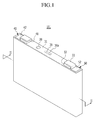
- FIG. 1 is a perspective view showing a rechargeable battery according to a first exemplary embodiment of the present invention and FIG. 2 is a cross-sectional view taken along line II-II in FIG. 1 .
- a rechargeable battery 101 includes an electrode assembly 10 stacked by interposing a separator 13 between a positive electrode 11 and a negative electrode 12, a case 26 in which the electrode assembly 10 is installed, and a cap assembly 30 coupled with an opening of the case 26.
- the rechargeable battery 101 according to the first exemplary embodiment of the present invention is a lithium ion rechargeable battery.
- a square rechargeable battery will be described by way of example.
- the present invention is not limited thereto and embodiments of the present invention may be applied to battery having various shapes such as a lithium polymer battery, a cylindrical battery, or the like.
- the positive electrode 11 and the negative electrode 12 each include a coating part where an active material is coated on a surface of a current collector formed of a thin metal foil, and an uncoated part where the active material is not coated thereon.
- the positive electrode uncoated part 11a is formed on the other side end of the positive electrode 11 in a length direction of the positive electrode 11 and the negative electrode uncoated part 12a is formed on one side end in a length direction of the negative electrode 12. Moreover, the positive electrode 11 and the negative electrode 12 are stacked after interposing a separator, which is an insulator, therebetween.
- the above-mentioned electrode assembly 10 may be formed in a wound structure, having the separator between the positive electrode and the negative electrode formed of a plurality of sheets.
- the case 26 is formed in an approximately rectangular parallelepiped shape and one surface thereof is provided with an opened opening.
- the cap assembly 30 includes a cap plate 31 covering the opening of the case 26, a first terminal 21 disposed on the cap plate 31 and electrically connected with the positive electrode 11, a second terminal 22 disposed on the cap plate 31 and electrically connected with the negative electrode 12, and a vent member 39 having a notch 39a formed therein so as to be fractured according to a set internal pressure.
- the vent member 39 is installed so as to cover the vent hole 34 formed in the cap plate 31.
- the cap plate 31 is formed of a thin metal plate and has an electrolyte inlet 37 formed at one side thereof. Further, the cap plate 31 is provide with a sealing closure 38 fixedly installed to seal the electrolyte inlet 37
- the first terminal 21 and the second terminal 22 are installed to pass through terminal holes H1 and H2 formed in the cap plate 31 and are electrically connected to the electrode assembly 10, respectively. That is, the first terminal 21 is installed to electrically connect with the positive electrode 11.
- the first terminal 21 is electrically connected with the positive electrode 11 via a current collector member 25.
- the first terminal 21 is provided with a sealing member 40 enclosing the first terminal 21.
- the second terminal 22 is installed to electrically connect with the negative electrode 12.
- the second terminal 22 is electrically connected with the negative electrode 12 via the current collector member 27.
- the second terminal 22 is provided with the sealing member 50 enclosing a portion of the second terminal 22.
- FIG. 3 is a perspective view of a terminal according to the first exemplary embodiment of the present invention and FIG. 4 is exploded perspective view showing to cut-way a cap plate and a sealing member according to the first exemplary embodiment of the present invention.
- a second terminal 22 and members coupled with the second terminal 22 are formed in a symmetrical structure with a first terminal 21 and members coupled with the first terminal 21, and thus a detailed description of the second terminal 22 will be substituted with the description for the first terminal 21 and members coupled with the first terminal 21.
- the first terminal 21 is formed of a plate-shaped and includes an upper connecting part (outer portion) 21a positioned on an outer side of the case 26, a current collector connecting part 21b (middle connection portion) inserted in the case 26 and coupled with the current collector member 25, and a middle connecting part 21c (current collection connecting portion) bended between the upper connecting part 21a and the current collector connecting part 21b.
- the upper connecting part 21a is disposed in parallel with the cap plate 31 over an upper portion of the cap plate 31.
- the upper connecting part 21a is formed toward a center of the cap plate 31 from the middle connecting part 21c.
- the current collector connecting part 21b is disposed in parallel with the cap plate 31 under the cap plate 31. On the lower surface of the current collector connecting part 21b there is formed a current collector protrusion 21d that is fitted into the current collector member 25. In this embodiment, the current collector protrusion 21d is fixed to the current collector member 25 by welding.
- the current collector connecting part 21b is formed toward a side end of the cap plate 31 from the middle connecting part 21c. As described above, in this embodiment, the upper connecting part 21a and the current collector connecting part 21b are formed to extend in the opposite direction each other from the middle connecting part 21c.
- the middle connecting part 21c is bended at an approximately perpendicular angle between the upper connecting part 21a and the current collector connecting part 21b to connect the upper connecting part 21a with the current collector connecting part 21b, and is inserted into a hole 43 formed in the sealing member 40. In addition, the middle connecting part 21c is inserted to be through the cap plate 31.
- the upper connecting part 21a and the current collector connecting part 21b are disposed in parallel with the cap plate 31, and the middle connecting part 21c is vertically disposed to the upper connecting part 21a and the current collector connecting part 21b.
- the sealing member 40 includes an upper sealing part 41 seated on the cap plate 31 and a lower sealing part 42 inserted into and fixed to a terminal hole H1 formed in the cap plate 31.
- the upper sealing part 41 is positioned between the lower surface of the upper connecting part 21a and the upper surface of the cap plate 31, and supports the upper connecting part 21a to be spaced apart from the cap plate 31.
- the upper sealing part 41 serves to insulate the cap plate 31 and the upper connecting part 21a from each other.
- the hole 43 into which the middle connecting part 21c is inserted, and in the lower surface thereof is formed a seating groove 49 into which the current collector connecting part 21b is inserted along the hole 43.
- a protruding block part 32 On the terminal hole H1 is formed a protruding block part 32, and in the lower sealing part 42 is formed a supporting part 46 fitted into and coupled with the block part 32.
- the block part 32 is formed of a protrusion and is formed in the circumferential direction on an inner peripheral surface of the terminal hole H1.
- the supporting part 46 is formed of a groove into which the block part 32 is inserted and is formed along the circumference of the lower sealing part 42.
- the block part 32 and the supporting part 46 when the block part 32 and the supporting part 46 are formed, a contact area of the inside of the terminal hole H1 and the sealing member 40 is increased, thereby improving the sealing performance.
- the block part 32 and the supporting part 46 when moisture is infiltrated into between the cap plate 31 and the sealing member 40, the block part 32 and the supporting part 46 can prevent the moisture from infiltrating.
- the sealing member 40 is formed by an insert molding method in a state in which the first terminal 21 is installed on the cap plate 31. Therefore, the sealing member 40 is fixedly installed in the cap plate 31 simultaneously with being formed and can be stably fixed on the cap plate 31 enclosing the first terminal 21.
- the second terminal 22 includes an upper connecting part positioned over an upper portion of the cap plate 31, a current collector connecting part inserted into the case 26 and coupled with a current collector member 27, and a middle connecting part bended between the upper connecting part and the current collector connecting part.
- the second terminal 22 is provided with the sealing member 50 that is inserted into the terminal hole H2 to support the second terminal 22.
- the sealing member 50 is formed by the insert molding method in a state in which the second terminal is installed on the cap plate.
- a current collector connecting part 21b has a length D1 smaller than a length D2 of the terminal hole H1.
- the terminal hole H1 has a longish rectangular cross section in one direction, and the current collector connecting part 21b is positioned under the terminal hole.
- the length D1 of the current collector connecting part 21b may be a 60% to 95% of the length D2 of the terminal hole H1.
- the current collector connecting part 21b has a length D1 smaller than the length D2 of the terminal hole H1, thereby making it possible to prevent of the current collector connecting part 21b and the cap plate 31 from being short-circuited.
- the current collector connecting part 21b has a length longer than that of the terminal hole H1 since the current collector connecting part 21b is positioned under the cap plate 31, in case a foreign material such as water and the like is infiltrated into a gab between the sealing member 40 and the cap plate 31, thereby causing the short circuit between the current collector connecting part 21b and the cap plate 31 due to the foreign material.
- the current collector connecting part 21b since the current collector connecting part 21b is positioned only under the terminal hole H1, it is possible to block basically that the water and the current collector connecting part 21b are contacted even if the water soaked.
- the upper connecting part 21a has a length longer than that of the current collector connecting part 21b.
- the length of the upper connecting part 21a may have a length of 3 times to 1.2 times than that of the current collector connecting part 21b. Therefore, the center of gravity of the positive electrode terminal 21 is inclined toward the upper connecting part 21a and the upper connecting part 21a pressurizes the upper surface of the cap plate 31 to be stably fixed thereto.
- the first terminal 21 is arranged such the portion of the first terminal 21 inside the case 26 does not overlap with the first surface of the case 26 when considered in a direction normal to the surface of the case 26 that comprises the terminal hole H1. Hence, short circuits between the portion of the first terminal 21 inside the case 26 (e.g. the current collector connecting portion 21b) and the cap plate 31 due to the foreign material can be reduced.
- the battery may be considered to be within a housing with the terminal hole formed in a first surface of the housing.
- the terminal is arranged such the portion of the terminal inside the housing does not overlap with the first surface of the housing when considered in a direction normal to the first surface of the housing.
- the terminal could comprise other shapes.
- the terminal could comprise an outer portion located outside the housing and a connecting portion arranged to extend through the terminal hole.
- the outer portion may be disposed in a plane parallel to the first surface, with the connecting portion extending through the terminal hole and connected directly to the current collector, for example by extending into a receiving hole formed in a surface of the current collector.
- FIG. FIG. 6 is an enlarged cross-sectional view showing a portion of the rechargeable battery according to a second exemplary embodiment of the present invention.
- the rechargeable battery according to the second exemplary embodiment of the present invention has the same structure as those of the rechargeable battery according to the first embodiment of the present invention except for a structure of a cap plate 71 and a sealing member 60 and therefore, the description of the same structure will be omitted.
- the cap plate 71 according to this embodiment of the present invention is provided with a terminal hole 72, and the terminal hole 72 has a first terminal 21 and a sealing member 60 insertedly installed therein.
- the first terminal 21 includes an upper connecting part 21a positioned on an outer side of the case, a current collector connecting part 21b inserted in the case, and a middle connecting part 21c bended between the upper connecting part 21a and the current collector connecting part 21b.
- the sealing member 60 includes an upper sealing part 61 seated on the cap plate 71 and a lower sealing part 62 inserted into and fixed to a terminal hole 72.
- the upper sealing part 61 is positioned between the lower surface of the upper connecting part 21a and the upper surface of the cap plate 71 and supports the upper connecting part 21a to be spaced apart from the cap plate 71.
- the sealing member 60 is formed by the insert molding method in a state in which the first terminal 21 is installed on the cap plate 71. Therefore, the sealing member 60 is fixedly installed into the cap plate 71 simultaneously with being formed and may be stably fixed on the cap plate 71 enclosing the first terminal 21.
- a block part 72a having a concave groove
- a supporting part 63 fitted into and coupled with the block part 72a.
- the block part 72a is formed in the circumferential direction in an inner peripheral surface of the terminal hole 72.
- the supporting part 63 is formed of a protrusion inserted into the block part 32 and is formed along circumference of the lower sealing part 62.
- the block part 72a of a groove shaped and the supporting part 73 of a protrusion shaped are formed, a contact area of the inside of the terminal hole 72 and the sealing member 60 is increased, thereby improving the sealing performance.
- the block part 72a and the supporting part 63 can prevent the moisture from infiltrating.
- FIG. 7 is an enlarged cross-sectional view showing a portion of the rechargeable battery according to a third exemplary embodiment of the present invention.
- the rechargeable battery according to the third exemplary embodiment of the present invention has the same structure as those of the rechargeable battery according to the first embodiment of the present invention except for a structure of a cap plate 91 and a sealing member 80 and therefore, the description of the same structure will be omitted.
- the cap plate 91 according to this embodiment of the present invention is provided with a terminal hole 92, and the terminal hole 92 has a first terminal 21 and a sealing member 80 insertedly installed therein.
- the first terminal 21 includes an upper connecting part 21a positioned on an outer side of a case, a current collector connecting part 21b inserted in the case, and a middle connecting part 21c bended between the upper connecting part 21a and the current collector connecting part 21b.
- the sealing member 80 includes an upper sealing part 81 seated on the cap plate 91 and a lower sealing part 82 inserted into and fixed to a terminal hole 92.
- the upper sealing part 81 is positioned between the lower surface of the upper connecting part 21a and the upper surface of the cap plate 91 and supports the upper connecting part 21a to be spaced apart from the cap plate 91.
- the terminal hole 92 is provided with the block part 92a formed in a concave-convex shape in which a concave portion and a convex portion are alternately disposed, and the lower sealing part 82 is provided with the supporting part 83 fitted into and coupled with the block part 92a.
- the block part 92a is formed in the circumferential direction in an inner peripheral surface of the terminal hole 92.
- the supporting part 83 is formed in a concave-convex shape in which the convex portion and the concave portion inserted into the concave portion and the convex portion of the block part 92a are alternately disposed to each other, and is formed along a circumference of the lower sealing part 82.
- the block part 92a having the concave-convex shape and the supporting part 83 having the concave-convex shape fitted into and coupled with the block part 92a are formed, a contact area of the inside of the terminal hole 92 and the sealing member 40 is increased, thereby improving the sealing performance.
- the block part 92a and the supporting part 83 can prevent the moisture from infiltrating.
- a rechargeable battery comprising: a housing comprising a terminal hole in a first surface of the housing; an electrode assembly housed inside the housing; a current collector electrically connected to the electrode assembly; a terminal arranged to extend from inside the housing to outside the housing through the terminal hole, wherein the terminal comprises a portion inside the housing that is electrically connected to the current collector and a portion that is outside of the housing; a sealing member formed around a portion of the terminal so as to seal the terminal hole; wherein the terminal is arranged such the portion of the terminal inside the housing does not overlap with the first surface of the housing when considered in a direction normal to the first surface.
- the housing comprises a first seal part arranged on an inner surface of the housing that defines the terminal hole, and the sealing member comprises a second seal part for engagement with the first seal part.
- the first seal part may comprise a protrusion and the second seal part may comprise a groove or the first seal part may comprise a groove and the second seal part may comprise a protrusion.
- the first seal part may comprise a series of alternately disposed concave and convex portions along an inner surface of the housing that defines the terminal hole and the second seal part may comprise a corresponding series of alternately disposed concave and convex portions for engagement with the first seal part.
- the housing comprises a case and a cap plate which is coupled with the case, with the terminal hole being formed in the cap plate.
- the terminal comprises: a current collector connecting portion inside the housing that is electrically connected to the current collector, a middle connecting portion arranged to extend through the terminal hole and an outer portion located outside the housing.
- the connecting portion can be arranged to connect the current collector connecting portion to the outer portion.
- the middle connecting portion and the current collector connecting portion can be provided by the same portion of the terminal.
- the current collector connecting portion, middle connecting portion and the outer portion are arranged to form a step shape.
- the outer portion may be arranged to extend in a direction towards a central region of the first surface.
- the sealing member comprises a first sealing part arranged between the outer portion of the terminal and the first surface of the housing and between a first surface of the middle connecting portion and a first portion of an inner surface of the housing that defines the terminal hole, and a second sealing part arranged between a second surface of the middle connecting portion and a second portion of the inner surface of the housing that defines the terminal hole.
- the second sealing part comprises a groove for receiving the current collector connecting portion.
- the outer portion and the current collector connecting portion are respectively disposed in a first plane and a second plane.
- the first and second planes are planes parallel to the first surface.
- the length of the current collector connecting portion is smaller than the diameter of the terminal hole.
- the length of the current collector connecting portion of the terminal may be 60% to 95% of the diameter of the terminal hole.
- the length of the outer portion may be greater than the length of the current collector connecting portion. In particular, in some embodiments, the length of the outer portion may be from 1.2 to 3 times greater than the length of the current collector connecting portion.
- the current collector connecting portion comprises a first engagement part and the current collector comprises a second engagement part for engagement with the first engagement part.
- the first engagement part may comprise a current collector connecting protrusion formed on a surface of the current collector connecting portion
- the second engagement part may comprise a groove or hole in a portion of the current collector for receiving the current collector connecting protrusion.
- the sealing member may be formed by an insert molding method.
Abstract
Description
- The described technology relates generally to a rechargeable battery, and more particularly, to a rechargeable battery having an improved terminal structure.
- Rechargeable batteries are batteries that can be rechargeable and dischargeable, unlike primary batteries that cannot be rechargeable. Low-capacity rechargeable batteries are used for small portable electronic devices such as mobile phones, laptop computers, and camcorders, and large-capacity chargeable batteries are widely used as power supplies for driving motors for hybrid cars or the like.
- Recently, high-output rechargeable batteries using a non-aqueous electrolyte with high energy density have been developed. The high-output rechargeable batteries are configured of large-capacity battery modules in which a plurality of rechargeable batteries are connected to each other in series so as to be used for driving motors for devices requiring large power, for example, electric cars, or the like.
- In addition, one battery module is generally configured of a plurality of rechargeable batteries interconnected in series. The rechargeable battery can be configured of a cylindrical shape, a squared shape, or the like. The rechargeable battery has a negative electrode terminal and a positive electrode terminal protruding to the outside. The negative electrode terminal and positive electrode terminal are installed to be through a cap plate. A sealing member for sealing is installed between the terminals and the cap plate.
- The sealing member is generally configured of a gasket in which column shaped terminals are inserted, thereby closely adhering to the terminal and a terminal hole. In order to install the sealing member as described above, an assembling process becomes complicated. In addition, in case a defect occurs in the sealing member a sealing performance between the terminals and the cap plate is deteriorated to leak an electrolyte and rainwater and the like are infiltrated therebetween to cause a short circuit.
- The above information disclosed in this background section is only for enhancement of understanding of the background of the described technology and therefore it may contain information that does not form the prior art that is already known in this country to a person of ordinary skill in the art.
- The exemplary embodiments have been made to solve the above problem and to provide a rechargeable battery having advantages of an improved stability.
- An exemplary embodiment provides a rechargeable battery, including: an electrode assembly including a negative electrode and a positive electrode; a case having a space with the electrode assembly installed therein; a cap plate coupled with the case and having a terminal hole into which a terminal is inserted formed therein; the terminal electrically connected to the electrode assembly and protruding to the outside of the case; and a sealing member inserted into the terminal hole while partially enclosing the terminal, wherein the terminal includes an upper connecting part protruding to the outside of the case and a current collector connecting part positioned in the case and a lower connecting part has a length smaller than that of the terminal hole.
- The length of the lower connecting part may be a 60% to 95% of the length of the terminal hole. Further, on an inside of the terminal hole is formed a block part and in the sealing member may be formed a supporting part fitted into and coupled with the block part.
- When the block part is formed of a protrusion, the supporting part may be formed of a groove into which the block part is inserted, on the contrary if the block part is formed of the groove, the supporting part may be formed of the protrusion to be inserted into the block part.
- In addition, the block part may be formed in a concave-convex shape in which a concave portion and a convex portion are alternately disposed and may be formed along an inner circumferential surface of the terminal hole.
- The terminal is formed between the upper connecting part and the current collector connecting part and may further include a middle connecting part bended therebetween, which the upper connecting part and the current collector connecting part may be disposed in parallel with the cap plate.
- The upper connecting part is formed toward a center of the cap plate from the middle connecting part and the current collector connecting part may be formed toward a side end of the cap plate from the middle connecting part.
- The sealing member includes an upper sealing part disposed between the upper connecting part and the cap plate and a lower sealing part inserted and fixed into the terminal hole formed in the cap plate, and the supporting part may be formed at a circumference of the lower sealing part.
- In the lower sealing part may be formed a hole into which the middle connecting part is inserted, and in a lower surface of the lower sealing part may be formed a seating groove into which the collector connecting part is inserted along the hole.
- The sealing member may be formed by an insert injection. The current collector connecting part is connected to the electrode assembly via a current collector member and on a lower surface of the current collector connecting part may be formed the protrusion be inserted into the current collector member.
- According to an exemplary embodiment, the current collector connecting part has a length shorter than that of the terminal hole, the sealing member is inserted into and installed in the terminal hole, thereby improving sealability.
- In addition, an inner side of the terminal hole is formed with the block part and the sealing member is formed with the supporting part fitted into and coupled with the block part, thereby improving the sealability.
- According to an aspect of the invention, there is provided a rechargeable battery, comprising: a housing comprising a terminal hole in a first surface of the housing; an electrode assembly housed inside the housing; a current collector electrically connected to the electrode assembly; a terminal arranged to extend from inside the housing to outside the housing through the terminal hole, wherein the terminal comprises a portion inside the housing that is electrically connected to the current collector and a portion that is outside of the housing; a sealing member formed around a portion of the terminal so as to seal the terminal hole; wherein the terminal is arranged such the portion of the terminal inside the housing does not overlap with the first surface of the housing when considered in a direction normal to the first surface. Preferred features of this aspect are set out in claims 2 to 15.
-
FIG. 1 is a perspective view showing a rechargeable battery according to a first exemplary embodiment of the present invention. -
FIG. 2 is a cross-sectional view taken along line II-II ofFIG. 1 . -
FIG. 3 is a perspective view of a terminal according to the first exemplary embodiment of the present invention. -
FIG. 4 is exploded perspective view showing to cut-way a cap plate and a sealing member according to the first exemplary embodiment of the present invention. -
FIG. 5 is an enlarged cross-sectional view showing a portion of the rechargeable battery according to the first exemplary embodiment of the present invention. -
FIG. 6 is an enlarged cross-sectional view showing a portion of the rechargeable battery according to a second exemplary embodiment of the present invention. -
FIG. 7 is an enlarged cross-sectional view showing a portion of the rechargeable battery according to a third exemplary embodiment of the present invention. - Hereinafter, exemplary embodiments of the present invention will be described in detail with reference to the accompanying drawings so that they can be easily practiced by those skilled in the art to which the present invention pertains. However, the present invention may be implemented in various different types and is not limited to the embodiments provided in the present description. In addition, in the present description and the accompanying drawings, the same reference numerals denote the same components.
-
FIG. 1 is a perspective view showing a rechargeable battery according to a first exemplary embodiment of the present invention andFIG. 2 is a cross-sectional view taken along line II-II inFIG. 1 . - Describing with referring to
FIGS. 1 and2 , arechargeable battery 101 according to the first exemplary embodiment of the present invention includes anelectrode assembly 10 stacked by interposing aseparator 13 between apositive electrode 11 and anegative electrode 12, acase 26 in which theelectrode assembly 10 is installed, and acap assembly 30 coupled with an opening of thecase 26. - The
rechargeable battery 101 according to the first exemplary embodiment of the present invention is a lithium ion rechargeable battery. Herein, a square rechargeable battery will be described by way of example. However, the present invention is not limited thereto and embodiments of the present invention may be applied to battery having various shapes such as a lithium polymer battery, a cylindrical battery, or the like. - In this embodiment, the
positive electrode 11 and thenegative electrode 12 each include a coating part where an active material is coated on a surface of a current collector formed of a thin metal foil, and an uncoated part where the active material is not coated thereon. - The positive electrode uncoated
part 11a is formed on the other side end of thepositive electrode 11 in a length direction of thepositive electrode 11 and the negative electrodeuncoated part 12a is formed on one side end in a length direction of thenegative electrode 12. Moreover, thepositive electrode 11 and thenegative electrode 12 are stacked after interposing a separator, which is an insulator, therebetween. - However, embodiments of the present invention are not limited thereto. The above-mentioned
electrode assembly 10 may be formed in a wound structure, having the separator between the positive electrode and the negative electrode formed of a plurality of sheets. - The
case 26 is formed in an approximately rectangular parallelepiped shape and one surface thereof is provided with an opened opening. Thecap assembly 30 includes acap plate 31 covering the opening of thecase 26, afirst terminal 21 disposed on thecap plate 31 and electrically connected with thepositive electrode 11, asecond terminal 22 disposed on thecap plate 31 and electrically connected with thenegative electrode 12, and avent member 39 having anotch 39a formed therein so as to be fractured according to a set internal pressure. Thevent member 39 is installed so as to cover thevent hole 34 formed in thecap plate 31. - The
cap plate 31 is formed of a thin metal plate and has anelectrolyte inlet 37 formed at one side thereof. Further, thecap plate 31 is provide with asealing closure 38 fixedly installed to seal theelectrolyte inlet 37 - The
first terminal 21 and thesecond terminal 22 are installed to pass through terminal holes H1 and H2 formed in thecap plate 31 and are electrically connected to theelectrode assembly 10, respectively. That is, thefirst terminal 21 is installed to electrically connect with thepositive electrode 11. Thefirst terminal 21 is electrically connected with thepositive electrode 11 via acurrent collector member 25. Thefirst terminal 21 is provided with a sealingmember 40 enclosing thefirst terminal 21. - The
second terminal 22 is installed to electrically connect with thenegative electrode 12. Thesecond terminal 22 is electrically connected with thenegative electrode 12 via thecurrent collector member 27. Thesecond terminal 22 is provided with the sealingmember 50 enclosing a portion of thesecond terminal 22. -
FIG. 3 is a perspective view of a terminal according to the first exemplary embodiment of the present invention andFIG. 4 is exploded perspective view showing to cut-way a cap plate and a sealing member according to the first exemplary embodiment of the present invention. - Describing with reference to
FIGS. 3 and4 , asecond terminal 22 and members coupled with thesecond terminal 22 are formed in a symmetrical structure with afirst terminal 21 and members coupled with thefirst terminal 21, and thus a detailed description of thesecond terminal 22 will be substituted with the description for thefirst terminal 21 and members coupled with thefirst terminal 21. - In this embodiment, the
first terminal 21 is formed of a plate-shaped and includes an upper connecting part (outer portion) 21a positioned on an outer side of thecase 26, a currentcollector connecting part 21b (middle connection portion) inserted in thecase 26 and coupled with thecurrent collector member 25, and amiddle connecting part 21c (current collection connecting portion) bended between the upper connectingpart 21a and the currentcollector connecting part 21b. - In this embodiment, the upper connecting
part 21a is disposed in parallel with thecap plate 31 over an upper portion of thecap plate 31. The upper connectingpart 21a is formed toward a center of thecap plate 31 from themiddle connecting part 21c. - The current
collector connecting part 21b is disposed in parallel with thecap plate 31 under thecap plate 31. On the lower surface of the currentcollector connecting part 21b there is formed acurrent collector protrusion 21d that is fitted into thecurrent collector member 25. In this embodiment, thecurrent collector protrusion 21d is fixed to thecurrent collector member 25 by welding. The currentcollector connecting part 21b is formed toward a side end of thecap plate 31 from themiddle connecting part 21c. As described above, in this embodiment, the upper connectingpart 21a and the currentcollector connecting part 21b are formed to extend in the opposite direction each other from themiddle connecting part 21c. - The
middle connecting part 21c is bended at an approximately perpendicular angle between the upper connectingpart 21a and the currentcollector connecting part 21b to connect the upper connectingpart 21a with the currentcollector connecting part 21b, and is inserted into ahole 43 formed in the sealingmember 40. In addition, themiddle connecting part 21c is inserted to be through thecap plate 31. - The upper connecting
part 21a and the currentcollector connecting part 21b are disposed in parallel with thecap plate 31, and themiddle connecting part 21c is vertically disposed to the upper connectingpart 21a and the currentcollector connecting part 21b. - The sealing
member 40 includes anupper sealing part 41 seated on thecap plate 31 and alower sealing part 42 inserted into and fixed to a terminal hole H1 formed in thecap plate 31. Theupper sealing part 41 is positioned between the lower surface of the upper connectingpart 21a and the upper surface of thecap plate 31, and supports the upper connectingpart 21a to be spaced apart from thecap plate 31. In addition, the upper sealingpart 41 serves to insulate thecap plate 31 and the upper connectingpart 21a from each other. - In the
lower sealing part 42 is formed thehole 43 into which themiddle connecting part 21c is inserted, and in the lower surface thereof is formed aseating groove 49 into which the currentcollector connecting part 21b is inserted along thehole 43. - On the terminal hole H1 is formed a
protruding block part 32, and in thelower sealing part 42 is formed a supportingpart 46 fitted into and coupled with theblock part 32. Theblock part 32 is formed of a protrusion and is formed in the circumferential direction on an inner peripheral surface of the terminal hole H1. The supportingpart 46 is formed of a groove into which theblock part 32 is inserted and is formed along the circumference of thelower sealing part 42. - As set forth above, when the
block part 32 and the supportingpart 46 are formed, a contact area of the inside of the terminal hole H1 and the sealingmember 40 is increased, thereby improving the sealing performance. In addition, when moisture is infiltrated into between thecap plate 31 and the sealingmember 40, theblock part 32 and the supportingpart 46 can prevent the moisture from infiltrating. - The sealing
member 40 is formed by an insert molding method in a state in which thefirst terminal 21 is installed on thecap plate 31. Therefore, the sealingmember 40 is fixedly installed in thecap plate 31 simultaneously with being formed and can be stably fixed on thecap plate 31 enclosing thefirst terminal 21. - Similarly to the
first terminal 21, thesecond terminal 22 includes an upper connecting part positioned over an upper portion of thecap plate 31, a current collector connecting part inserted into thecase 26 and coupled with acurrent collector member 27, and a middle connecting part bended between the upper connecting part and the current collector connecting part. In addition, thesecond terminal 22 is provided with the sealingmember 50 that is inserted into the terminal hole H2 to support thesecond terminal 22. The sealingmember 50 is formed by the insert molding method in a state in which the second terminal is installed on the cap plate. - As shown in
FIG. 5 , a currentcollector connecting part 21b has a length D1 smaller than a length D2 of the terminal hole H1. The terminal hole H1 has a longish rectangular cross section in one direction, and the currentcollector connecting part 21b is positioned under the terminal hole. The length D1 of the currentcollector connecting part 21b may be a 60% to 95% of the length D2 of the terminal hole H1. - According to this embodiment of the present invention, the current
collector connecting part 21b has a length D1 smaller than the length D2 of the terminal hole H1, thereby making it possible to prevent of the currentcollector connecting part 21b and thecap plate 31 from being short-circuited. When the currentcollector connecting part 21b has a length longer than that of the terminal hole H1, since the currentcollector connecting part 21b is positioned under thecap plate 31, in case a foreign material such as water and the like is infiltrated into a gab between the sealingmember 40 and thecap plate 31, thereby causing the short circuit between the currentcollector connecting part 21b and thecap plate 31 due to the foreign material. However, according to this embodiment of the present invention, since the currentcollector connecting part 21b is positioned only under the terminal hole H1, it is possible to block basically that the water and the currentcollector connecting part 21b are contacted even if the water soaked. - In addition, the upper connecting
part 21a has a length longer than that of the currentcollector connecting part 21b. The length of the upper connectingpart 21a may have a length of 3 times to 1.2 times than that of the currentcollector connecting part 21b. Therefore, the center of gravity of thepositive electrode terminal 21 is inclined toward the upper connectingpart 21a and the upper connectingpart 21a pressurizes the upper surface of thecap plate 31 to be stably fixed thereto. - Hence, in this embodiment, as a result of D1 being smaller than D2, the
first terminal 21 is arranged such the portion of thefirst terminal 21 inside thecase 26 does not overlap with the first surface of thecase 26 when considered in a direction normal to the surface of thecase 26 that comprises the terminal hole H1. Hence, short circuits between the portion of thefirst terminal 21 inside the case 26 (e.g. the currentcollector connecting portion 21b) and thecap plate 31 due to the foreign material can be reduced. - It will be appreciated that, more generally, the battery may be considered to be within a housing with the terminal hole formed in a first surface of the housing. In such embodiments, it can be considered that the terminal is arranged such the portion of the terminal inside the housing does not overlap with the first surface of the housing when considered in a direction normal to the first surface of the housing.
- It will be apprecaited that the terminal could comprise other shapes. For example, the terminal could comprise an outer portion located outside the housing and a connecting portion arranged to extend through the terminal hole. For example, the outer portion may be disposed in a plane parallel to the first surface, with the connecting portion extending through the terminal hole and connected directly to the current collector, for example by extending into a receiving hole formed in a surface of the current collector.
- FIG.
FIG. 6 is an enlarged cross-sectional view showing a portion of the rechargeable battery according to a second exemplary embodiment of the present invention. - The rechargeable battery according to the second exemplary embodiment of the present invention has the same structure as those of the rechargeable battery according to the first embodiment of the present invention except for a structure of a
cap plate 71 and a sealingmember 60 and therefore, the description of the same structure will be omitted. Thecap plate 71 according to this embodiment of the present invention is provided with aterminal hole 72, and theterminal hole 72 has afirst terminal 21 and a sealingmember 60 insertedly installed therein. - The
first terminal 21 includes an upper connectingpart 21a positioned on an outer side of the case, a currentcollector connecting part 21b inserted in the case, and amiddle connecting part 21c bended between the upper connectingpart 21a and the currentcollector connecting part 21b. - The sealing
member 60 includes anupper sealing part 61 seated on thecap plate 71 and alower sealing part 62 inserted into and fixed to aterminal hole 72. Theupper sealing part 61 is positioned between the lower surface of the upper connectingpart 21a and the upper surface of thecap plate 71 and supports the upper connectingpart 21a to be spaced apart from thecap plate 71. The sealingmember 60 is formed by the insert molding method in a state in which thefirst terminal 21 is installed on thecap plate 71. Therefore, the sealingmember 60 is fixedly installed into thecap plate 71 simultaneously with being formed and may be stably fixed on thecap plate 71 enclosing thefirst terminal 21. - In the
terminal hole 72 is formed ablock part 72a having a concave groove, and on thelower sealing part 62 is formed a supportingpart 63 fitted into and coupled with theblock part 72a. Theblock part 72a is formed in the circumferential direction in an inner peripheral surface of theterminal hole 72. The supportingpart 63 is formed of a protrusion inserted into theblock part 32 and is formed along circumference of thelower sealing part 62. - As set forth above, when the
block part 72a of a groove shaped and the supporting part 73 of a protrusion shaped are formed, a contact area of the inside of theterminal hole 72 and the sealingmember 60 is increased, thereby improving the sealing performance. In addition, when moisture is infiltrated into between thecap plate 71 and the sealingmember 60, theblock part 72a and the supportingpart 63 can prevent the moisture from infiltrating. -
FIG. 7 is an enlarged cross-sectional view showing a portion of the rechargeable battery according to a third exemplary embodiment of the present invention. - The rechargeable battery according to the third exemplary embodiment of the present invention has the same structure as those of the rechargeable battery according to the first embodiment of the present invention except for a structure of a
cap plate 91 and a sealingmember 80 and therefore, the description of the same structure will be omitted. - The
cap plate 91 according to this embodiment of the present invention is provided with aterminal hole 92, and theterminal hole 92 has afirst terminal 21 and a sealingmember 80 insertedly installed therein. - The
first terminal 21 includes an upper connectingpart 21a positioned on an outer side of a case, a currentcollector connecting part 21b inserted in the case, and amiddle connecting part 21c bended between the upper connectingpart 21a and the currentcollector connecting part 21b. - The sealing
member 80 includes anupper sealing part 81 seated on thecap plate 91 and alower sealing part 82 inserted into and fixed to aterminal hole 92. Theupper sealing part 81 is positioned between the lower surface of the upper connectingpart 21a and the upper surface of thecap plate 91 and supports the upper connectingpart 21a to be spaced apart from thecap plate 91. - The
terminal hole 92 is provided with theblock part 92a formed in a concave-convex shape in which a concave portion and a convex portion are alternately disposed, and thelower sealing part 82 is provided with the supportingpart 83 fitted into and coupled with theblock part 92a. Theblock part 92a is formed in the circumferential direction in an inner peripheral surface of theterminal hole 92. The supportingpart 83 is formed in a concave-convex shape in which the convex portion and the concave portion inserted into the concave portion and the convex portion of theblock part 92a are alternately disposed to each other, and is formed along a circumference of thelower sealing part 82. - As describe above, when the
block part 92a having the concave-convex shape and the supportingpart 83 having the concave-convex shape fitted into and coupled with theblock part 92a are formed, a contact area of the inside of theterminal hole 92 and the sealingmember 40 is increased, thereby improving the sealing performance. In addition, when moisture is infiltrated into between thecap plate 91 and the sealingmember 80, theblock part 92a and the supportingpart 83 can prevent the moisture from infiltrating. - As discused above, embodiments of the present invention provide a rechargeable battery, comprising: a housing comprising a terminal hole in a first surface of the housing; an electrode assembly housed inside the housing; a current collector electrically connected to the electrode assembly; a terminal arranged to extend from inside the housing to outside the housing through the terminal hole, wherein the terminal comprises a portion inside the housing that is electrically connected to the current collector and a portion that is outside of the housing; a sealing member formed around a portion of the terminal so as to seal the terminal hole; wherein the terminal is arranged such the portion of the terminal inside the housing does not overlap with the first surface of the housing when considered in a direction normal to the first surface.
- In some embodiments, the housing comprises a first seal part arranged on an inner surface of the housing that defines the terminal hole, and the sealing member comprises a second seal part for engagement with the first seal part. In some such embodiments, the first seal part may comprise a protrusion and the second seal part may comprise a groove or the first seal part may comprise a groove and the second seal part may comprise a protrusion. The first seal part may comprise a series of alternately disposed concave and convex portions along an inner surface of the housing that defines the terminal hole and the second seal part may comprise a corresponding series of alternately disposed concave and convex portions for engagement with the first seal part.
- In some embodiments, the housing comprises a case and a cap plate which is coupled with the case, with the terminal hole being formed in the cap plate.
- In some embodiments, the terminal comprises: a current collector connecting portion inside the housing that is electrically connected to the current collector, a middle connecting portion arranged to extend through the terminal hole and an outer portion located outside the housing. In such embodiments, the connecting portion can be arranged to connect the current collector connecting portion to the outer portion. In some such embodiments, the middle connecting portion and the current collector connecting portion can be provided by the same portion of the terminal.
- In some embodiments, the current collector connecting portion, middle connecting portion and the outer portion are arranged to form a step shape. In some such embodiments, the outer portion may be arranged to extend in a direction towards a central region of the first surface.
- In some embodiments, the sealing member comprises a first sealing part arranged between the outer portion of the terminal and the first surface of the housing and between a first surface of the middle connecting portion and a first portion of an inner surface of the housing that defines the terminal hole, and a second sealing part arranged between a second surface of the middle connecting portion and a second portion of the inner surface of the housing that defines the terminal hole. In some embodiments, the second sealing part comprises a groove for receiving the current collector connecting portion.
- In some embodiments, the outer portion and the current collector connecting portion are respectively disposed in a first plane and a second plane. In some such embodiments, the first and second planes are planes parallel to the first surface.
- In some embodiments, the length of the current collector connecting portion is smaller than the diameter of the terminal hole. The length of the current collector connecting portion of the terminal may be 60% to 95% of the diameter of the terminal hole. The length of the outer portion may be greater than the length of the current collector connecting portion. In particular, in some embodiments, the length of the outer portion may be from 1.2 to 3 times greater than the length of the current collector connecting portion.
- In some embodiments, the current collector connecting portion comprises a first engagement part and the current collector comprises a second engagement part for engagement with the first engagement part. The first engagement part may comprise a current collector connecting protrusion formed on a surface of the current collector connecting portion, and the second engagement part may comprise a groove or hole in a portion of the current collector for receiving the current collector connecting protrusion.
- In some embodiments, the sealing member may be formed by an insert molding method.
- While this invention has been described in connection with what is presently considered to be practical exemplary embodiments, it is to be understood that the invention is not limited to the disclosed embodiments, but, on the contrary, is intended to cover various modifications and equivalent arrangements included within the scope of the appended claims.
Claims (15)
- A rechargeable battery (101), comprising:a housing comprising a terminal hole (H1, H2) in a first surface of the housing;an electrode assembly (10) housed inside the housing;a current collector (25, 27) electrically connected to the electrode assembly (10);a terminal (21, 22) arranged to extend from inside the housing to outside the housing through the terminal hole (H1, H2), wherein the terminal comprises a portion inside the housing that is electrically connected to the current collector (25, 27) and a portion that is outside of the housing;a sealing member (40, 50, 60, 80) formed around a portion of the terminal (21, 22) so as to seal the terminal hole (H1, H2);wherein the terminal (21, 22) is arranged such the portion of the terminal (21, 22) inside the housing does not overlap with the first surface of the housing when considered in a direction normal to the first surface.
- The rechargeable battery (101) according to claim 1, wherein
the housing comprises a first seal part (32, 72a, 92a) arranged on an inner surface of the housing that defines the terminal hole (H1, H2); and
the sealing member (40, 50, 60, 80) comprises a second seal part (46, 63, 83) for engagement with the first seal part (32, 72a, 92a). - The rechargeable battery (101) according to claim 2, wherein:the first seal part (32) comprises a protrusion and the second seal part (46) comprises a groove; orthe first seal part comprises a groove (72a) and the second seal part comprises a protrusion (63).
- The rechargeable battery (101) according to claim 2, wherein:the first seal part (92a) comprises a series of alternately disposed concave and convex portions along an inner surface of the housing that defines the terminal hole (H1, H2); andthe second seal part (83) comprises a corresponding series of alternately disposed concave and convex portions for engagement with the first seal part (92a).
- The rechargeable battery (101) according to any one of claims 1 to 4, wherein the housing comprises a case (26) and a cap plate (31, 71, 91) which is coupled with the case (26), wherein the terminal hole (H1, H2) is formed in the cap plate (31, 71, 91).
- The rechargeable battery (101) according to any one of claims 1 to 5, wherein the terminal (21, 22) comprises:a current collector connecting portion (21b) inside the housing that is electrically connected to the current collector (25, 27);a middle connecting portion (21c) arranged to extend through the terminal hole (H1, H2); andan outer portion (21a) located outside the housing, wherein the connecting portion (21c) is arranged to connect the current collector connecting portion (21b) to the outer portion (21a).
- The rechargeable battery (101) according to claim 6, wherein the current collector connecting portion (21b), middle connecting portion (21c) and the outer portion (21a) are arranged to form a step shape; optionally wherein the outer portion (21a) is arranged to extend in a direction towards a central region of the first surface.
- The rechargeable battery (101) according to claim 7, wherein the sealing member (40, 50, 60, 80) comprises:a first sealing part (41, 61, 81) arranged between the outer portion (21a) of the terminal and the first surface of the housing and between a first surface of the middle connecting portion (21c) and a first portion of an inner surface of the housing that defines the terminal hole (H1, H2); anda second sealing part (42, 62, 82) arranged between a second surface of the middle connecting portion (21c) and a second portion of the inner surface of the housing that defines the terminal hole (H1, H2).
- The rechargeable battery (101) according to any one of claim 6 to 8, wherein the outer portion (21a) and the current collector connecting portion (21b) are respectively disposed in a first plane and a second plane, optionally wherein the first and second planes are planes parallel to the first surface.
- The rechargeable battery (101) according to any one of claims 6 to 9, wherein a length (D1) of the current collector connecting portion (21b) is smaller than a diameter (D2) of the terminal hole (H1, H2).
- The rechargeable battery (101) according to claim 10, wherein the length (D1) of the current collector connecting portion (21b) of the terminal is 60% to 95% of the diameter of the terminal hole (H1, H2).
- The rechargeable battery (101) according to according to claim 10 or 11, wherein a length of the outer portion (21a) is greater than the length (D1) of the current collector connecting portion (21b); optionally wherein the length of the outer portion (21a) is from 1.2 to 3 times greater than the length (D1) of the current collector connecting portion (21b).
- The rechargeable battery (101) according to any one of claims 6 to 12, wherein the current collector connecting portion (21b) comprises a first engagement part and the current collector (25, 27) comprises a second engagement part for engagement with the first engagement part.
- The rechargeable battery (101) according to claim 13, wherein the first engagement part comprises a current collector connecting protrusion (21d) formed on a surface of the current collector connecting portion (21b), and the second engagement part comprises a groove or hole in a portion of the current collector (25, 27) for receiving the current collector connecting protrusion (21d).
- The rechargeable battery (101) according to any one of claims 1 to 14, wherein the sealing member (40, 50, 60, 80) is formed by an insert molding method.
Applications Claiming Priority (2)
| Application Number | Priority Date | Filing Date | Title |
|---|---|---|---|
| US201361828029P | 2013-05-28 | 2013-05-28 | |
| US14/227,223 US9412992B2 (en) | 2013-05-28 | 2014-03-27 | Rechargeable battery |
Publications (2)
| Publication Number | Publication Date |
|---|---|
| EP2808918A1 true EP2808918A1 (en) | 2014-12-03 |
| EP2808918B1 EP2808918B1 (en) | 2018-09-12 |
Family
ID=50389355
Family Applications (1)
| Application Number | Title | Priority Date | Filing Date |
|---|---|---|---|
| EP14162757.0A Active EP2808918B1 (en) | 2013-05-28 | 2014-03-31 | Rechargeable battery having an improved terminal structure |
Country Status (5)
| Country | Link |
|---|---|
| US (1) | US9412992B2 (en) |
| EP (1) | EP2808918B1 (en) |
| JP (1) | JP6444061B2 (en) |
| KR (1) | KR102208999B1 (en) |
| CN (1) | CN104183814B (en) |
Families Citing this family (7)
| Publication number | Priority date | Publication date | Assignee | Title |
|---|---|---|---|---|
| KR102515096B1 (en) * | 2015-06-16 | 2023-03-28 | 삼성에스디아이 주식회사 | Rechargeable battery having current collector member |
| JP2017079153A (en) * | 2015-10-21 | 2017-04-27 | 日立オートモティブシステムズ株式会社 | Square secondary battery |
| KR102573330B1 (en) | 2016-06-24 | 2023-08-30 | 삼성에스디아이 주식회사 | Rechargeable battery |
| KR102335021B1 (en) * | 2016-10-21 | 2021-12-02 | 삼성에스디아이 주식회사 | Rechargeable battery and module of the same |
| CN209766578U (en) * | 2019-05-13 | 2019-12-10 | 宁德时代新能源科技股份有限公司 | Secondary battery |
| CN110212124A (en) * | 2019-07-17 | 2019-09-06 | 池州市骏智机电科技有限公司 | A kind of battery cap and preparation method thereof based on blocky pole |
| WO2024020227A1 (en) * | 2022-07-22 | 2024-01-25 | Our Next Energy, Inc. | Cap assembly |
Citations (2)
| Publication number | Priority date | Publication date | Assignee | Title |
|---|---|---|---|---|
| US20120156548A1 (en) * | 2010-12-17 | 2012-06-21 | Dukjung Kim | Secondary Battery and Battery Pack Including the Same |
| US20130108916A1 (en) * | 2011-11-02 | 2013-05-02 | Jang-Hyun Song | Rechargeable battery |
Family Cites Families (20)
| Publication number | Priority date | Publication date | Assignee | Title |
|---|---|---|---|---|
| JP2630158B2 (en) * | 1992-03-30 | 1997-07-16 | 新神戸電機株式会社 | Terminal sealing part of sealed lead-acid battery |
| JPH09320630A (en) * | 1996-05-28 | 1997-12-12 | Furukawa Battery Co Ltd:The | Liquid type lead acid battery |
| JP2003208879A (en) | 2002-01-10 | 2003-07-25 | Mitsubishi Heavy Ind Ltd | Secondary battery |
| JP4898138B2 (en) * | 2005-04-25 | 2012-03-14 | 三菱重工業株式会社 | Nonaqueous electrolyte secondary battery with battery internal pressure automatic adjustment mechanism |
| KR101201815B1 (en) * | 2005-10-14 | 2012-11-15 | 삼성에스디아이 주식회사 | Secondary battery |
| JP4785759B2 (en) | 2006-02-27 | 2011-10-05 | 三星エスディアイ株式会社 | Secondary battery |
| JP5147206B2 (en) * | 2006-08-11 | 2013-02-20 | 三洋電機株式会社 | Nonaqueous electrolyte secondary battery |
| JP4539763B2 (en) * | 2008-06-13 | 2010-09-08 | トヨタ自動車株式会社 | electrode |
| CN201238060Y (en) * | 2008-07-29 | 2009-05-13 | 武汉银泰科技电源股份有限公司 | Valve-controlled lead acid accumulator terminal |
| KR101050298B1 (en) | 2008-12-03 | 2011-07-19 | 삼성에스디아이 주식회사 | Secondary battery |
| JP5402318B2 (en) | 2009-06-30 | 2014-01-29 | 株式会社Gsユアサ | battery |
| JP5378134B2 (en) * | 2009-09-29 | 2013-12-25 | 豊田合成株式会社 | Battery cover member |
| JP5492653B2 (en) * | 2010-05-07 | 2014-05-14 | 日立ビークルエナジー株式会社 | Secondary battery |
| CN201732822U (en) * | 2010-05-17 | 2011-02-02 | 深圳市雄韬电源科技有限公司 | Sealing structure of battery terminal |
| US20110300414A1 (en) | 2010-06-07 | 2011-12-08 | Woonseong Baek | Cap assembly and rechargeable battery having the same |
| KR101233322B1 (en) * | 2010-08-31 | 2013-02-14 | 로베르트 보쉬 게엠베하 | Rechargeable battery |
| CN201994369U (en) * | 2011-04-18 | 2011-09-28 | 美美电池有限公司 | Terminal sealing structure for battery |
| JP5589955B2 (en) * | 2011-05-16 | 2014-09-17 | 日立オートモティブシステムズ株式会社 | Prismatic secondary battery |
| CN202259476U (en) * | 2011-09-28 | 2012-05-30 | 江苏双登集团有限公司 | Terminal sealing structure for lead-acid storage battery |
| CN202797106U (en) * | 2012-07-30 | 2013-03-13 | 比亚迪股份有限公司 | Seal assembly of lithium ion battery |
-
2014
- 2014-03-27 US US14/227,223 patent/US9412992B2/en active Active
- 2014-03-31 EP EP14162757.0A patent/EP2808918B1/en active Active
- 2014-04-17 KR KR1020140046309A patent/KR102208999B1/en active IP Right Grant
- 2014-05-15 CN CN201410204708.9A patent/CN104183814B/en active Active
- 2014-05-26 JP JP2014107870A patent/JP6444061B2/en active Active
Patent Citations (2)
| Publication number | Priority date | Publication date | Assignee | Title |
|---|---|---|---|---|
| US20120156548A1 (en) * | 2010-12-17 | 2012-06-21 | Dukjung Kim | Secondary Battery and Battery Pack Including the Same |
| US20130108916A1 (en) * | 2011-11-02 | 2013-05-02 | Jang-Hyun Song | Rechargeable battery |
Also Published As
| Publication number | Publication date |
|---|---|
| CN104183814A (en) | 2014-12-03 |
| CN104183814B (en) | 2019-08-16 |
| JP2014232729A (en) | 2014-12-11 |
| JP6444061B2 (en) | 2018-12-26 |
| US20140356700A1 (en) | 2014-12-04 |
| EP2808918B1 (en) | 2018-09-12 |
| KR20140139958A (en) | 2014-12-08 |
| KR102208999B1 (en) | 2021-01-27 |
| US9412992B2 (en) | 2016-08-09 |
Similar Documents
| Publication | Publication Date | Title |
|---|---|---|
| EP2808918B1 (en) | Rechargeable battery having an improved terminal structure | |
| US9312565B2 (en) | Rechargeable battery | |
| EP2816638B1 (en) | Rechargeable battery | |
| US8367242B2 (en) | Rechargeable battery | |
| CN106356490B (en) | Rechargeable battery and battery module including the same | |
| EP3109926B1 (en) | Rechargeable battery and rechargeable battery module | |
| US8722239B2 (en) | Terminal of rechargeable battery, method of assembling the terminal of rechargeable battery, rechargeable battery module and method of assembling the rechargeable battery module | |
| KR102246736B1 (en) | Rechargeable battery | |
| US9023516B2 (en) | Rechargeable battery and module thereof | |
| US9660249B2 (en) | Rechargeable battery having a fuse | |
| CN106058134B (en) | Rechargeable battery | |
| KR101683213B1 (en) | Rechargeable battery | |
| US20160248073A1 (en) | Rechargeable battery and module thereof | |
| US20130115494A1 (en) | Rechargeable battery | |
| KR20140124247A (en) | Rechargeable battery | |
| CN105932193B (en) | Rechargeable battery | |
| KR101181803B1 (en) | Rechargeable battery | |
| EP3509127A1 (en) | Secondary battery | |
| KR102470495B1 (en) | Secondary Battery and Method for Manufacturing The Same | |
| CN109314196B (en) | Rechargeable battery | |
| KR20130040576A (en) | Rechargeable battery | |
| JP2015228362A (en) | Secondary battery | |
| KR20160050703A (en) | Rechargeable battery | |
| KR102439848B1 (en) | Rechargeable battery | |
| KR102530350B1 (en) | Rechargeable battery |
Legal Events
| Date | Code | Title | Description |
|---|---|---|---|
| PUAI | Public reference made under article 153(3) epc to a published international application that has entered the european phase |
Free format text: ORIGINAL CODE: 0009012 |
|
| 17P | Request for examination filed |
Effective date: 20140331 |
|
| AK | Designated contracting states |
Kind code of ref document: A1 Designated state(s): AL AT BE BG CH CY CZ DE DK EE ES FI FR GB GR HR HU IE IS IT LI LT LU LV MC MK MT NL NO PL PT RO RS SE SI SK SM TR |
|
| AX | Request for extension of the european patent |
Extension state: BA ME |
|
| R17P | Request for examination filed (corrected) |
Effective date: 20150603 |
|
| RBV | Designated contracting states (corrected) |
Designated state(s): AL AT BE BG CH CY CZ DE DK EE ES FI FR GB GR HR HU IE IS IT LI LT LU LV MC MK MT NL NO PL PT RO RS SE SI SK SM TR |
|
| RIC1 | Information provided on ipc code assigned before grant |
Ipc: H01M 10/0525 20100101ALI20180322BHEP Ipc: H01M 2/06 20060101AFI20180322BHEP Ipc: H01M 2/30 20060101ALI20180322BHEP Ipc: H01M 2/04 20060101ALN20180322BHEP |
|
| RIC1 | Information provided on ipc code assigned before grant |
Ipc: H01M 2/04 20060101ALN20180323BHEP Ipc: H01M 2/06 20060101AFI20180323BHEP Ipc: H01M 2/30 20060101ALI20180323BHEP Ipc: H01M 10/0525 20100101ALI20180323BHEP |
|
| GRAP | Despatch of communication of intention to grant a patent |
Free format text: ORIGINAL CODE: EPIDOSNIGR1 |
|
| STAA | Information on the status of an ep patent application or granted ep patent |
Free format text: STATUS: GRANT OF PATENT IS INTENDED |
|
| INTG | Intention to grant announced |
Effective date: 20180504 |
|
| GRAS | Grant fee paid |
Free format text: ORIGINAL CODE: EPIDOSNIGR3 |
|
| GRAA | (expected) grant |
Free format text: ORIGINAL CODE: 0009210 |
|
| STAA | Information on the status of an ep patent application or granted ep patent |
Free format text: STATUS: THE PATENT HAS BEEN GRANTED |
|
| AK | Designated contracting states |
Kind code of ref document: B1 Designated state(s): AL AT BE BG CH CY CZ DE DK EE ES FI FR GB GR HR HU IE IS IT LI LT LU LV MC MK MT NL NO PL PT RO RS SE SI SK SM TR |
|
| REG | Reference to a national code |
Ref country code: GB Ref legal event code: FG4D |
|
| REG | Reference to a national code |
Ref country code: CH Ref legal event code: EP |
|
| REG | Reference to a national code |
Ref country code: IE Ref legal event code: FG4D |
|
| REG | Reference to a national code |
Ref country code: DE Ref legal event code: R096 Ref document number: 602014032131 Country of ref document: DE |
|
| REG | Reference to a national code |
Ref country code: AT Ref legal event code: REF Ref document number: 1041622 Country of ref document: AT Kind code of ref document: T Effective date: 20181015 |
|
| REG | Reference to a national code |
Ref country code: NL Ref legal event code: MP Effective date: 20180912 |
|
| REG | Reference to a national code |
Ref country code: LT Ref legal event code: MG4D |
|
| PG25 | Lapsed in a contracting state [announced via postgrant information from national office to epo] |
Ref country code: BG Free format text: LAPSE BECAUSE OF FAILURE TO SUBMIT A TRANSLATION OF THE DESCRIPTION OR TO PAY THE FEE WITHIN THE PRESCRIBED TIME-LIMIT Effective date: 20181212 Ref country code: SE Free format text: LAPSE BECAUSE OF FAILURE TO SUBMIT A TRANSLATION OF THE DESCRIPTION OR TO PAY THE FEE WITHIN THE PRESCRIBED TIME-LIMIT Effective date: 20180912 Ref country code: NO Free format text: LAPSE BECAUSE OF FAILURE TO SUBMIT A TRANSLATION OF THE DESCRIPTION OR TO PAY THE FEE WITHIN THE PRESCRIBED TIME-LIMIT Effective date: 20181212 Ref country code: LT Free format text: LAPSE BECAUSE OF FAILURE TO SUBMIT A TRANSLATION OF THE DESCRIPTION OR TO PAY THE FEE WITHIN THE PRESCRIBED TIME-LIMIT Effective date: 20180912 Ref country code: RS Free format text: LAPSE BECAUSE OF FAILURE TO SUBMIT A TRANSLATION OF THE DESCRIPTION OR TO PAY THE FEE WITHIN THE PRESCRIBED TIME-LIMIT Effective date: 20180912 Ref country code: GR Free format text: LAPSE BECAUSE OF FAILURE TO SUBMIT A TRANSLATION OF THE DESCRIPTION OR TO PAY THE FEE WITHIN THE PRESCRIBED TIME-LIMIT Effective date: 20181213 Ref country code: FI Free format text: LAPSE BECAUSE OF FAILURE TO SUBMIT A TRANSLATION OF THE DESCRIPTION OR TO PAY THE FEE WITHIN THE PRESCRIBED TIME-LIMIT Effective date: 20180912 |
|
| PG25 | Lapsed in a contracting state [announced via postgrant information from national office to epo] |
Ref country code: LV Free format text: LAPSE BECAUSE OF FAILURE TO SUBMIT A TRANSLATION OF THE DESCRIPTION OR TO PAY THE FEE WITHIN THE PRESCRIBED TIME-LIMIT Effective date: 20180912 Ref country code: AL Free format text: LAPSE BECAUSE OF FAILURE TO SUBMIT A TRANSLATION OF THE DESCRIPTION OR TO PAY THE FEE WITHIN THE PRESCRIBED TIME-LIMIT Effective date: 20180912 Ref country code: HR Free format text: LAPSE BECAUSE OF FAILURE TO SUBMIT A TRANSLATION OF THE DESCRIPTION OR TO PAY THE FEE WITHIN THE PRESCRIBED TIME-LIMIT Effective date: 20180912 |
|
| REG | Reference to a national code |
Ref country code: AT Ref legal event code: MK05 Ref document number: 1041622 Country of ref document: AT Kind code of ref document: T Effective date: 20180912 |
|
| PG25 | Lapsed in a contracting state [announced via postgrant information from national office to epo] |
Ref country code: IT Free format text: LAPSE BECAUSE OF FAILURE TO SUBMIT A TRANSLATION OF THE DESCRIPTION OR TO PAY THE FEE WITHIN THE PRESCRIBED TIME-LIMIT Effective date: 20180912 Ref country code: EE Free format text: LAPSE BECAUSE OF FAILURE TO SUBMIT A TRANSLATION OF THE DESCRIPTION OR TO PAY THE FEE WITHIN THE PRESCRIBED TIME-LIMIT Effective date: 20180912 Ref country code: PL Free format text: LAPSE BECAUSE OF FAILURE TO SUBMIT A TRANSLATION OF THE DESCRIPTION OR TO PAY THE FEE WITHIN THE PRESCRIBED TIME-LIMIT Effective date: 20180912 Ref country code: ES Free format text: LAPSE BECAUSE OF FAILURE TO SUBMIT A TRANSLATION OF THE DESCRIPTION OR TO PAY THE FEE WITHIN THE PRESCRIBED TIME-LIMIT Effective date: 20180912 Ref country code: IS Free format text: LAPSE BECAUSE OF FAILURE TO SUBMIT A TRANSLATION OF THE DESCRIPTION OR TO PAY THE FEE WITHIN THE PRESCRIBED TIME-LIMIT Effective date: 20190112 Ref country code: CZ Free format text: LAPSE BECAUSE OF FAILURE TO SUBMIT A TRANSLATION OF THE DESCRIPTION OR TO PAY THE FEE WITHIN THE PRESCRIBED TIME-LIMIT Effective date: 20180912 Ref country code: AT Free format text: LAPSE BECAUSE OF FAILURE TO SUBMIT A TRANSLATION OF THE DESCRIPTION OR TO PAY THE FEE WITHIN THE PRESCRIBED TIME-LIMIT Effective date: 20180912 Ref country code: RO Free format text: LAPSE BECAUSE OF FAILURE TO SUBMIT A TRANSLATION OF THE DESCRIPTION OR TO PAY THE FEE WITHIN THE PRESCRIBED TIME-LIMIT Effective date: 20180912 Ref country code: NL Free format text: LAPSE BECAUSE OF FAILURE TO SUBMIT A TRANSLATION OF THE DESCRIPTION OR TO PAY THE FEE WITHIN THE PRESCRIBED TIME-LIMIT Effective date: 20180912 |
|
| PG25 | Lapsed in a contracting state [announced via postgrant information from national office to epo] |
Ref country code: SM Free format text: LAPSE BECAUSE OF FAILURE TO SUBMIT A TRANSLATION OF THE DESCRIPTION OR TO PAY THE FEE WITHIN THE PRESCRIBED TIME-LIMIT Effective date: 20180912 Ref country code: PT Free format text: LAPSE BECAUSE OF FAILURE TO SUBMIT A TRANSLATION OF THE DESCRIPTION OR TO PAY THE FEE WITHIN THE PRESCRIBED TIME-LIMIT Effective date: 20190112 Ref country code: SK Free format text: LAPSE BECAUSE OF FAILURE TO SUBMIT A TRANSLATION OF THE DESCRIPTION OR TO PAY THE FEE WITHIN THE PRESCRIBED TIME-LIMIT Effective date: 20180912 |
|
| REG | Reference to a national code |
Ref country code: DE Ref legal event code: R097 Ref document number: 602014032131 Country of ref document: DE |
|
| PLBE | No opposition filed within time limit |
Free format text: ORIGINAL CODE: 0009261 |
|
| STAA | Information on the status of an ep patent application or granted ep patent |
Free format text: STATUS: NO OPPOSITION FILED WITHIN TIME LIMIT |
|
| PG25 | Lapsed in a contracting state [announced via postgrant information from national office to epo] |
Ref country code: DK Free format text: LAPSE BECAUSE OF FAILURE TO SUBMIT A TRANSLATION OF THE DESCRIPTION OR TO PAY THE FEE WITHIN THE PRESCRIBED TIME-LIMIT Effective date: 20180912 |
|
| 26N | No opposition filed |
Effective date: 20190613 |
|
| PG25 | Lapsed in a contracting state [announced via postgrant information from national office to epo] |
Ref country code: SI Free format text: LAPSE BECAUSE OF FAILURE TO SUBMIT A TRANSLATION OF THE DESCRIPTION OR TO PAY THE FEE WITHIN THE PRESCRIBED TIME-LIMIT Effective date: 20180912 |
|
| PG25 | Lapsed in a contracting state [announced via postgrant information from national office to epo] |
Ref country code: MC Free format text: LAPSE BECAUSE OF FAILURE TO SUBMIT A TRANSLATION OF THE DESCRIPTION OR TO PAY THE FEE WITHIN THE PRESCRIBED TIME-LIMIT Effective date: 20180912 |
|
| REG | Reference to a national code |
Ref country code: CH Ref legal event code: PL |
|
| PG25 | Lapsed in a contracting state [announced via postgrant information from national office to epo] |
Ref country code: LU Free format text: LAPSE BECAUSE OF NON-PAYMENT OF DUE FEES Effective date: 20190331 |
|
| REG | Reference to a national code |
Ref country code: BE Ref legal event code: MM Effective date: 20190331 |
|
| PG25 | Lapsed in a contracting state [announced via postgrant information from national office to epo] |
Ref country code: LI Free format text: LAPSE BECAUSE OF NON-PAYMENT OF DUE FEES Effective date: 20190331 Ref country code: CH Free format text: LAPSE BECAUSE OF NON-PAYMENT OF DUE FEES Effective date: 20190331 Ref country code: IE Free format text: LAPSE BECAUSE OF NON-PAYMENT OF DUE FEES Effective date: 20190331 |
|
| PG25 | Lapsed in a contracting state [announced via postgrant information from national office to epo] |
Ref country code: BE Free format text: LAPSE BECAUSE OF NON-PAYMENT OF DUE FEES Effective date: 20190331 |
|
| PG25 | Lapsed in a contracting state [announced via postgrant information from national office to epo] |
Ref country code: TR Free format text: LAPSE BECAUSE OF FAILURE TO SUBMIT A TRANSLATION OF THE DESCRIPTION OR TO PAY THE FEE WITHIN THE PRESCRIBED TIME-LIMIT Effective date: 20180912 |
|
| PG25 | Lapsed in a contracting state [announced via postgrant information from national office to epo] |
Ref country code: MT Free format text: LAPSE BECAUSE OF NON-PAYMENT OF DUE FEES Effective date: 20190331 |
|
| REG | Reference to a national code |
Ref country code: DE Ref legal event code: R079 Ref document number: 602014032131 Country of ref document: DE Free format text: PREVIOUS MAIN CLASS: H01M0002060000 Ipc: H01M0050172000 |
|
| PG25 | Lapsed in a contracting state [announced via postgrant information from national office to epo] |
Ref country code: CY Free format text: LAPSE BECAUSE OF FAILURE TO SUBMIT A TRANSLATION OF THE DESCRIPTION OR TO PAY THE FEE WITHIN THE PRESCRIBED TIME-LIMIT Effective date: 20180912 |
|
| PG25 | Lapsed in a contracting state [announced via postgrant information from national office to epo] |
Ref country code: HU Free format text: LAPSE BECAUSE OF FAILURE TO SUBMIT A TRANSLATION OF THE DESCRIPTION OR TO PAY THE FEE WITHIN THE PRESCRIBED TIME-LIMIT; INVALID AB INITIO Effective date: 20140331 |
|
| PG25 | Lapsed in a contracting state [announced via postgrant information from national office to epo] |
Ref country code: MK Free format text: LAPSE BECAUSE OF FAILURE TO SUBMIT A TRANSLATION OF THE DESCRIPTION OR TO PAY THE FEE WITHIN THE PRESCRIBED TIME-LIMIT Effective date: 20180912 |
|
| PGFP | Annual fee paid to national office [announced via postgrant information from national office to epo] |
Ref country code: FR Payment date: 20230309 Year of fee payment: 10 |
|
| PGFP | Annual fee paid to national office [announced via postgrant information from national office to epo] |
Ref country code: GB Payment date: 20230223 Year of fee payment: 10 Ref country code: DE Payment date: 20230228 Year of fee payment: 10 |
|
| P01 | Opt-out of the competence of the unified patent court (upc) registered |
Effective date: 20230528 |