EP2808835A1 - Electronic tag remote control - Google Patents
Electronic tag remote control Download PDFInfo
- Publication number
- EP2808835A1 EP2808835A1 EP13275265.0A EP13275265A EP2808835A1 EP 2808835 A1 EP2808835 A1 EP 2808835A1 EP 13275265 A EP13275265 A EP 13275265A EP 2808835 A1 EP2808835 A1 EP 2808835A1
- Authority
- EP
- European Patent Office
- Prior art keywords
- electronic tag
- remote control
- cover
- slide cover
- case
- Prior art date
- Legal status (The legal status is an assumption and is not a legal conclusion. Google has not performed a legal analysis and makes no representation as to the accuracy of the status listed.)
- Withdrawn
Links
Images


Classifications
-
- H—ELECTRICITY
- H04—ELECTRIC COMMUNICATION TECHNIQUE
- H04Q—SELECTING
- H04Q9/00—Arrangements in telecontrol or telemetry systems for selectively calling a substation from a main station, in which substation desired apparatus is selected for applying a control signal thereto or for obtaining measured values therefrom
-
- G—PHYSICS
- G06—COMPUTING OR CALCULATING; COUNTING
- G06Q—INFORMATION AND COMMUNICATION TECHNOLOGY [ICT] SPECIALLY ADAPTED FOR ADMINISTRATIVE, COMMERCIAL, FINANCIAL, MANAGERIAL OR SUPERVISORY PURPOSES; SYSTEMS OR METHODS SPECIALLY ADAPTED FOR ADMINISTRATIVE, COMMERCIAL, FINANCIAL, MANAGERIAL OR SUPERVISORY PURPOSES, NOT OTHERWISE PROVIDED FOR
- G06Q10/00—Administration; Management
- G06Q10/08—Logistics, e.g. warehousing, loading or distribution; Inventory or stock management
- G06Q10/087—Inventory or stock management, e.g. order filling, procurement or balancing against orders
-
- G—PHYSICS
- G07—CHECKING-DEVICES
- G07C—TIME OR ATTENDANCE REGISTERS; REGISTERING OR INDICATING THE WORKING OF MACHINES; GENERATING RANDOM NUMBERS; VOTING OR LOTTERY APPARATUS; ARRANGEMENTS, SYSTEMS OR APPARATUS FOR CHECKING NOT PROVIDED FOR ELSEWHERE
- G07C9/00—Individual registration on entry or exit
- G07C9/00174—Electronically operated locks; Circuits therefor; Nonmechanical keys therefor, e.g. passive or active electrical keys or other data carriers without mechanical keys
- G07C9/00944—Details of construction or manufacture
Definitions
- the present invention relates to an electronic tag remote control, and more particularly, to an electronic tag remote control capable of increasing portability of a remover key by integrating the remover key used at the time of installing and separating the electronic tag into the remote control.
- the cost displaying label has used in a scheme in which it is attached to a place in the vicinity of displayed product by directly handwriting product information necessary to sell the product, for example, cost and discount information on a paper or printing the product information on the paper so as to conform to a standardized form.
- a traditional scheme looks as if it may be simple, convenient, and implemented at low cost, but in the case in which the standardized forms are used for tens of thousands of product items or more as in a large-scaled distribution market and costs are frequently changed, there is a limit as to what an existing paper label scheme is applied.
- a remote control When changing detailed information such as a brand name, costs, or the like on the electronic tag, a remote control is used.
- the remote control is directly owned by a manager in the distribution market and when changing the corresponding information, the manager presses a switch of the remote control at a position adjacent to the electronic tag so as to change the information.
- the above-mentioned electronic tag is inserted into a guide rail of a display stand on which the product is displayed and is then moved along the guide rail so as to be disposed at a center of a place on which the product is placed.
- the electronic tag When separating the electronic tag from the guide rail, the electronic tag may be separated from the guide rail by manipulating a stopper installed on a side of the electronic tag using a remover key.
- the remover key of separating the electronic tag from the guide rail separates the electronic tag from the guide rail by lifting a lower end of the electronic tag in a state in which the remover key is inserted into the stopper of the electronic tag. In this process, a tip of the remover key may be damaged by excessive force of a user.
- An object of the present invention is to provide an electronic tag remote control capable of increasing portability of a remover key by integrating the remover key used at the time of installing and separating the electronic tag into the remote control.
- a remote control adjusting product information and costs of an electronic tag installed in a guide rail
- the remote control including: a case having a battery received therein; a slide cover coupled to the case so as to prevent separation of the battery; a remover key configured integrally with the slide cover so as to separate the electronic tag from the guide rail; and cover catching holes formed in an inner portion of the case so as to adjust movement of the slide cover stepwise.
- the slide cover may have catching protrusions formed at both edges so as to be caught with the cover catching holes and at least a pair of catching protrusions may be formed along both edges.
- the cover catching holes are formed in an inner wall surface of the case at predetermined intervals so as to be coupled to the catching protrusion.
- the remover key may be configured of a connection part formed integrally with the slide cover and a tag separation piece bent at a predetermined angle at a tip of the connection part.
- the tag separation piece may have a groove formed at a central portion thereof and an interval of the groove may be formed so as to be the same as a size of a protruded protrusion configured at the electronic tag.
- connection part may have a rod shape formed so as to have a constant width and the connection part is connected to the slide cover while being tapered.
- the slide cover may have a cover movement groove formed in an external surface thereof and the cover movement protrusion may be configured of a plurality of semi-circular protrusions.
- FIG. 1 is an exploded perspective view showing a state in which a cover of a remote control is separate, according to an exemplary embodiment of the present invention
- FIG. 2 is a perspective view showing the remote control of an electronic tag according to an exemplary embodiment of the present invention
- FIG. 3 is a perspective view showing a state in which a remover key according to an exemplary embodiment of the present invention is slidably moved to one-stage in the remote control
- FIG. 4 is a perspective view showing a state in which the remover key according to the exemplary embodiment of the present invention is slidably moved to two-stage in the remote control
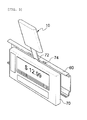
- FIG. 5 is a use state view showing a state in which the electronic tag is separated from a guide rail using the remover key according to the exemplary embodiment of the present invention.
- an electronic tag remote control 10 is used so as to wirelessly control an electronic tag 70 displaying product information and costs in a distribution market.
- the electronic tag 70 is inserted into a guide rail 60 configured at a front of a product display stand and has a protruded protrusion 72 and guide protrusions 74 formed on a circumference surface thereof in order to firmly hold a state in which the electronic tag 70 is coupled to the guide rail 60.
- the remover key 40 according to the exemplary embodiment of the present invention is configured integrally with the remote control 10, thereby making it possible to increase missing prevention and portability of the remover key 40.
- the remote control 10 includes a case 20 having a battery received therein, a slide cover 30 coupled to the case 20 so as to prevent separation of the battery 80, a remover key 40 configured integrally with the slide cover 30, and a cover catching hole 24 formed in the case so as to adjust a movement of the cover 30 stepwise.
- the case 20 which is manufactured by injecting synthetic resin, has an entire appearance changeable according to design requirements and may be configured approximately in a rectangular shape.
- the case 20 has a printed circuit board and a connection terminal formed in an inner portion thereof so that a circular battery 80 may be mounted thereon.
- slide cover 30 is coupled to the case so that the circular battery 80 is not moved or separated from the inner portion of the case 20 after the circular battery 80 is mounted in the inner portion of the case 20.
- the slide cover 30 opens and closes the inner portion of the case 20 according to the slide movement thereof.
- the slide cover 30 has a cover movement groove 32 formed in an external surface thereof, such that a user may conveniently move the slide cover 30.
- the cover movement groove 32 may be configured so as to have a predetermined depth or may also be configured in a serration shape.
- the slide cover 30 has the remover key 40 formed integrally therewith.
- the remover key 40 includes a connection part 42 and a tag separation piece 44 bent at a predetermined angle at a tip of the connection part 42.
- connection part 42 may have a rod shape configured so as to have a constant straight line width at a central position of the slide cover 30 or may be configured in a triangular shape tapered from the slide cover 30.
- the exemplary embodiment of the present invention shows a shape of the connection part 42 configured in the rod shape.
- the tag separation piece 44 formed at the tip of the connection part 42 has a shape bent at a predetermined angle and the bent angle may have a range less than 90°. In the case in which the bent angle is configured so as to exceed 90°, it is difficult for the remover key 40 to closely adhere to an edge of the case 20 and efficiency may be degraded when the electronic tag 70 is separated from the guide rail 60.
- the tag separation piece 44 may have a groove 44a formed at a central portion thereof.
- An interval of the groove 44a may be configured so as to be the same as or larger than a size of the protruded protrusion 72 configured at the electronic tag 70.
- the tip part of the tag separation piece 44 may be provided with an inclined surface 44b formed so as to have a thickness that becomes thin toward the tip part.
- the inclined surface 44 is configured so that the tag separation piece 44 may be further conveniently inserted into between the guide rail 60 and the electronic tag 70 when the electronic tag 70 is separated from the guide rail 60.
- the inner portion of the case 20 may be provided with the cover catching hole 24 so that the movement of the slide cover 30 is adjusted stepwise.
- the cover catching hole 24 may be formed on a moving path of the slide cover 30 and at least a pair of cover catching holes 24 are formed along inner wall surfaces facing each other in the inner portion of the case 20.
- the cover catching holes 24 may be formed at a position at which the slide cover 30 is closed, a position at which the slide cover 30 partially closes the circular battery 80, and a position at which the circular battery 80 is completely exposed, respectively.
- the slide cover 30 may have catching protrusions 34 formed at both edges thereof so that the position of the slide cover 30 is adjusted along the moving path by the cover catching hole 24 stepwise.
- At least a pair of catching protrusions 34 may be formed at both edges of the slide cover 30, respectively.
- connection part 42 and the tag separation piece 44 of the remover key are separated from the case 20 by moving the slide cover 30 of the remote control 10.
- the position of the slide cover 30 has a state in which the circular battery 80 received in the inner portion of the case 20 is partially closed and a state in which the catching protrusion 34 is caught with the cover catching hole 24, such that it is difficult to easily move the slide cover 30.
- the groove 44a is inserted into the protruded protrusion 72 of the electronic tag and the inclined surface 44b is inserted between the guide rail 60 and the electronic tag 70.
- the remote control 10 is vertically pressed using a principal of a lever. Once the electronic tag 70 is separated from the guide rail 60 by pressing the remote control 10, the electronic tag 70 may be conveniently taken out from the guide rail 60.
- the slide cover 30 is pushed as much as possible so that the catching protrusion 34 is caught with the cover catching hole 24 at an outer side of the case.
- the slide cover 30 completely exposes the circular battery 80, such that the circular battery 80 may be conveniently replaced.
- the electronic tag remote control 10 may perform manipulation of the electronic tag 70, may conveniently and quickly separate the electronic tag 70 from the guide rail 60 using the remover key 40, and may stably carry the remover key 40 while not missing.
- the electronic tag remote control may increase portability and storage performance of the remover key by integrating the remover key used at the time of installing and separating the electronic tag into the remote control.
Landscapes
- Engineering & Computer Science (AREA)
- Business, Economics & Management (AREA)
- Economics (AREA)
- Physics & Mathematics (AREA)
- General Physics & Mathematics (AREA)
- Human Resources & Organizations (AREA)
- Operations Research (AREA)
- Development Economics (AREA)
- Accounting & Taxation (AREA)
- Entrepreneurship & Innovation (AREA)
- Manufacturing & Machinery (AREA)
- Marketing (AREA)
- Finance (AREA)
- Quality & Reliability (AREA)
- Strategic Management (AREA)
- Tourism & Hospitality (AREA)
- General Business, Economics & Management (AREA)
- Theoretical Computer Science (AREA)
- Computer Networks & Wireless Communication (AREA)
- Selective Calling Equipment (AREA)
Abstract
Description
- This application claims the benefit of Korean Patent Application Serial No.
10-2013-0062957 - The present invention relates to an electronic tag remote control, and more particularly, to an electronic tag remote control capable of increasing portability of a remover key by integrating the remover key used at the time of installing and separating the electronic tag into the remote control.
- In order to exhibit and sell a number of products in a predetermined space such as a distribution market, a label displaying information and cost of the products has been used.
- In general, the cost displaying label has used in a scheme in which it is attached to a place in the vicinity of displayed product by directly handwriting product information necessary to sell the product, for example, cost and discount information on a paper or printing the product information on the paper so as to conform to a standardized form.
- A traditional scheme looks as if it may be simple, convenient, and implemented at low cost, but in the case in which the standardized forms are used for tens of thousands of product items or more as in a large-scaled distribution market and costs are frequently changed, there is a limit as to what an existing paper label scheme is applied.
- That is, if changes in costs of some product items among a number of product items have occurred, after a manager summarizes the changed costs and handwrites or prints the product information such as the changed costs, the manager have to go to where the corresponding products are sold and exhibited in the distribution market so as to replace the labels.
- Therefore, time and workers for performing the above-mentioned work and replacement whenever the cost information of the product is changed have been required and a need for improving the above-mentioned problems has increased due to nature of the large-scaled distribution market.
- In recent, the existing paper label has been significantly replaced with an electronic tag based on the above-mentioned market requirement.
- When changing detailed information such as a brand name, costs, or the like on the electronic tag, a remote control is used. The remote control is directly owned by a manager in the distribution market and when changing the corresponding information, the manager presses a switch of the remote control at a position adjacent to the electronic tag so as to change the information.
- The above-mentioned electronic tag is inserted into a guide rail of a display stand on which the product is displayed and is then moved along the guide rail so as to be disposed at a center of a place on which the product is placed.
- When separating the electronic tag from the guide rail, the electronic tag may be separated from the guide rail by manipulating a stopper installed on a side of the electronic tag using a remover key.
- However, the remover key of separating the electronic tag from the guide rail separates the electronic tag from the guide rail by lifting a lower end of the electronic tag in a state in which the remover key is inserted into the stopper of the electronic tag. In this process, a tip of the remover key may be damaged by excessive force of a user.
- In addition, since the stopper of the electronic tag is elastically supported by a spring, a position of the electronic tag is adjusted after lifting the stopper using the remover key. However, in this case, it is difficult to finely adjust the position of the electronic tag.
- In addition, since the remover key installing and separating the electronic tag has a very small size, there is a risk of missing the remover key. Indeed, most of managers in the distribution market have missed the remover key.
-
- (Patent Document 1) Cited Reference: Korean Patent Laid-Open Publication No.
2012-0048169 - An object of the present invention is to provide an electronic tag remote control capable of increasing portability of a remover key by integrating the remover key used at the time of installing and separating the electronic tag into the remote control.
- According to an exemplary embodiment of the present invention, there is provided a remote control adjusting product information and costs of an electronic tag installed in a guide rail, the remote control including: a case having a battery received therein; a slide cover coupled to the case so as to prevent separation of the battery; a remover key configured integrally with the slide cover so as to separate the electronic tag from the guide rail; and cover catching holes formed in an inner portion of the case so as to adjust movement of the slide cover stepwise.
- The slide cover may have catching protrusions formed at both edges so as to be caught with the cover catching holes and at least a pair of catching protrusions may be formed along both edges.
- The cover catching holes are formed in an inner wall surface of the case at predetermined intervals so as to be coupled to the catching protrusion.
- The remover key may be configured of a connection part formed integrally with the slide cover and a tag separation piece bent at a predetermined angle at a tip of the connection part.
- The tag separation piece may have a groove formed at a central portion thereof and an interval of the groove may be formed so as to be the same as a size of a protruded protrusion configured at the electronic tag.
- The connection part may have a rod shape formed so as to have a constant width and the connection part is connected to the slide cover while being tapered.
- The slide cover may have a cover movement groove formed in an external surface thereof and the cover movement protrusion may be configured of a plurality of semi-circular protrusions.
-
-
FIG. 1 is an exploded perspective view showing a state in which a cover of a remote control is separate, according to an exemplary embodiment of the present invention; -
FIG. 2 is a perspective view showing the remote control of an electronic tag according to an exemplary embodiment of the present invention; -
FIG. 3 is a perspective view showing a state in which a remover key according to an exemplary embodiment of the present invention is slidably moved to one stage in the remote control; -
FIG. 4 is a perspective view showing a state in which the remover key according to the exemplary embodiment of the present invention is slidably moved to two-stage in the remote control; -
FIG. 5 is a use state view showing a state in which the electronic tag is separated from a guide rail using the remover key according to the exemplary embodiment of the present invention. - Hereinafter, exemplary embodiments of the present invention will be described in detail with reference to the accompanying drawings.
-
FIG. 1 is an exploded perspective view showing a state in which a cover of a remote control is separate, according to an exemplary embodiment of the present invention,FIG. 2 is a perspective view showing the remote control of an electronic tag according to an exemplary embodiment of the present invention,FIG. 3 is a perspective view showing a state in which a remover key according to an exemplary embodiment of the present invention is slidably moved to one-stage in the remote control,FIG. 4 is a perspective view showing a state in which the remover key according to the exemplary embodiment of the present invention is slidably moved to two-stage in the remote control, andFIG. 5 is a use state view showing a state in which the electronic tag is separated from a guide rail using the remover key according to the exemplary embodiment of the present invention. - As shown, an electronic
tag remote control 10 according to an exemplary embodiment of the present invention is used so as to wirelessly control anelectronic tag 70 displaying product information and costs in a distribution market. - The
electronic tag 70 is inserted into aguide rail 60 configured at a front of a product display stand and has aprotruded protrusion 72 andguide protrusions 74 formed on a circumference surface thereof in order to firmly hold a state in which theelectronic tag 70 is coupled to theguide rail 60. - In this case, when the
electronic tag 70 is installed in theguide rail 60 and is then separated from theguide rail 60, aremover key 40 is used. - The
remover key 40 according to the exemplary embodiment of the present invention is configured integrally with theremote control 10, thereby making it possible to increase missing prevention and portability of theremover key 40. - The
remote control 10 according to the exemplary embodiment of the present invention includes acase 20 having a battery received therein, aslide cover 30 coupled to thecase 20 so as to prevent separation of thebattery 80, aremover key 40 configured integrally with theslide cover 30, and acover catching hole 24 formed in the case so as to adjust a movement of thecover 30 stepwise. - The
case 20, which is manufactured by injecting synthetic resin, has an entire appearance changeable according to design requirements and may be configured approximately in a rectangular shape. - Although not shown in the drawings, the
case 20 has a printed circuit board and a connection terminal formed in an inner portion thereof so that acircular battery 80 may be mounted thereon. - In addition, the
slide cover 30 is coupled to the case so that thecircular battery 80 is not moved or separated from the inner portion of thecase 20 after thecircular battery 80 is mounted in the inner portion of thecase 20. - The
slide cover 30 opens and closes the inner portion of thecase 20 according to the slide movement thereof. In this case, theslide cover 30 has acover movement groove 32 formed in an external surface thereof, such that a user may conveniently move theslide cover 30. - The
cover movement groove 32 may be configured so as to have a predetermined depth or may also be configured in a serration shape. - In addition, the
slide cover 30 has theremover key 40 formed integrally therewith. Theremover key 40 includes aconnection part 42 and atag separation piece 44 bent at a predetermined angle at a tip of theconnection part 42. - The
connection part 42 may have a rod shape configured so as to have a constant straight line width at a central position of theslide cover 30 or may be configured in a triangular shape tapered from theslide cover 30. - The exemplary embodiment of the present invention shows a shape of the
connection part 42 configured in the rod shape. - The
tag separation piece 44 formed at the tip of theconnection part 42 has a shape bent at a predetermined angle and the bent angle may have a range less than 90°. In the case in which the bent angle is configured so as to exceed 90°, it is difficult for theremover key 40 to closely adhere to an edge of thecase 20 and efficiency may be degraded when theelectronic tag 70 is separated from theguide rail 60. - In addition, the
tag separation piece 44 may have agroove 44a formed at a central portion thereof. An interval of thegroove 44a may be configured so as to be the same as or larger than a size of theprotruded protrusion 72 configured at theelectronic tag 70. - In addition, the tip part of the
tag separation piece 44 may be provided with aninclined surface 44b formed so as to have a thickness that becomes thin toward the tip part. Theinclined surface 44 is configured so that thetag separation piece 44 may be further conveniently inserted into between theguide rail 60 and theelectronic tag 70 when theelectronic tag 70 is separated from theguide rail 60. - Meanwhile, the inner portion of the
case 20 may be provided with thecover catching hole 24 so that the movement of theslide cover 30 is adjusted stepwise. Thecover catching hole 24 may be formed on a moving path of theslide cover 30 and at least a pair ofcover catching holes 24 are formed along inner wall surfaces facing each other in the inner portion of thecase 20. - In this case, the
cover catching holes 24 may be formed at a position at which theslide cover 30 is closed, a position at which theslide cover 30 partially closes thecircular battery 80, and a position at which thecircular battery 80 is completely exposed, respectively. - The
slide cover 30 may have catchingprotrusions 34 formed at both edges thereof so that the position of theslide cover 30 is adjusted along the moving path by thecover catching hole 24 stepwise. - At least a pair of catching
protrusions 34 may be formed at both edges of theslide cover 30, respectively. - By manipulating the electronic tag
remote control 10 according to the exemplary embodiment of the present invention configured as described above, product costs, information, or the like on theelectronic tag 70 installed in the guide rail of the distribution market are changed. - Thereafter, in the case in which the
electronic tag 70 needs to be separated from theguide rail 60, theconnection part 42 and thetag separation piece 44 of the remover key are separated from thecase 20 by moving theslide cover 30 of theremote control 10. - In this case, the position of the
slide cover 30 has a state in which thecircular battery 80 received in the inner portion of thecase 20 is partially closed and a state in which the catchingprotrusion 34 is caught with thecover catching hole 24, such that it is difficult to easily move theslide cover 30. - In this state, the
groove 44a is inserted into the protrudedprotrusion 72 of the electronic tag and theinclined surface 44b is inserted between theguide rail 60 and theelectronic tag 70. - After the
tag separation piece 44 is inserted between theguide rail 60 and theelectronic tag 70 as described above, theremote control 10 is vertically pressed using a principal of a lever. Once theelectronic tag 70 is separated from theguide rail 60 by pressing theremote control 10, theelectronic tag 70 may be conveniently taken out from theguide rail 60. - In addition, in the case in which the
circular battery 80 received in thecase 20 is replaced in thecase 20, theslide cover 30 is pushed as much as possible so that the catchingprotrusion 34 is caught with thecover catching hole 24 at an outer side of the case. - Once the catching
protrusion 34 is caught with thecover catching hole 24, theslide cover 30 completely exposes thecircular battery 80, such that thecircular battery 80 may be conveniently replaced. - Therefore, the electronic tag
remote control 10 according to the exemplary embodiment of the present invention may perform manipulation of theelectronic tag 70, may conveniently and quickly separate theelectronic tag 70 from theguide rail 60 using theremover key 40, and may stably carry the remover key 40 while not missing. - The electronic tag remote control according to the exemplary embodiment of the present invention may increase portability and storage performance of the remover key by integrating the remover key used at the time of installing and separating the electronic tag into the remote control.
- Although the electronic tag remote control according to the exemplary embodiment of the present invention has been described, the present invention is not limited thereto, but those skilled in the art will appreciate that various applications and modifications are possible.
Claims (10)
- A remote control adjusting product information and costs of an electronic tag installed in a guide rail, the remote control comprising:a case having a battery received therein;a slide cover coupled to the case so as to prevent separation of the battery;a remover key configured integrally with the slide cover so as to separate the electronic tag from the guide rail; andcover catching holes formed in an inner portion of the case so as to adjust movement of the slide cover stepwise.
- The electronic tag remote control according to claim 1, wherein the slide cover has catching protrusions formed at both edges so as to be caught with the cover catching holes.
- The electronic tag remote control according to claim 1, wherein the cover catching holes are formed in an inner wall surface of the case at predetermined intervals.
- The electronic tag remote control according to claim 1, wherein the remover key is configured of a connection part formed integrally with the slide cover and a tag separation piece bent at a predetermined angle at a tip of the connection part.
- The electronic tag remote control according to claim 4, wherein the tag separation piece has a groove formed at a central portion thereof.
- The electronic tag remote control according to claim 4, wherein the connection part has a rod shape formed so as to have a constant width.
- The electronic tag remote control according to claim 4, wherein the connection part is connected to the slide cover while being tapered.
- The electronic tag remote control according to claim 4, wherein the tag separation piece has an inclined surface having a thickness that becomes thin toward the tip.
- The electronic tag remote control according to claim 1, wherein the slide cover has a cover movement groove formed in an external surface thereof.
- The electronic tag remote control according to claim 1, wherein the cover movement protrusion is configured of a plurality of semi-circular protrusions.
Applications Claiming Priority (1)
| Application Number | Priority Date | Filing Date | Title |
|---|---|---|---|
| KR1020130062957A KR20140141324A (en) | 2013-05-31 | 2013-05-31 | Electronic tag remote control having remover key |
Publications (1)
| Publication Number | Publication Date |
|---|---|
| EP2808835A1 true EP2808835A1 (en) | 2014-12-03 |
Family
ID=49674244
Family Applications (1)
| Application Number | Title | Priority Date | Filing Date |
|---|---|---|---|
| EP13275265.0A Withdrawn EP2808835A1 (en) | 2013-05-31 | 2013-10-29 | Electronic tag remote control |
Country Status (2)
| Country | Link |
|---|---|
| EP (1) | EP2808835A1 (en) |
| KR (1) | KR20140141324A (en) |
Cited By (3)
| Publication number | Priority date | Publication date | Assignee | Title |
|---|---|---|---|---|
| CN105976480A (en) * | 2016-06-28 | 2016-09-28 | 宁波虎王保险箱有限公司 | Panel component for safe |
| US20190027009A1 (en) * | 2016-02-09 | 2019-01-24 | Noccela Oy | Electronic article surveillance tag |
| CN112265516A (en) * | 2020-11-18 | 2021-01-26 | 埃泰克汽车电子(芜湖)有限公司 | Automobile electronic intelligent key structure |
Citations (4)
| Publication number | Priority date | Publication date | Assignee | Title |
|---|---|---|---|---|
| EP0577878A1 (en) * | 1992-07-10 | 1994-01-12 | Siemens Aktiengesellschaft | Case for an electronic apparatus used for example as key for a motor vehicle locking system |
| US20060163348A1 (en) * | 2005-01-26 | 2006-07-27 | Yehuda Yoked | Remote controlled separable electronic price tag |
| JP2009293247A (en) * | 2008-06-04 | 2009-12-17 | Tokai Rika Co Ltd | Electronic key |
| WO2012089204A1 (en) * | 2010-12-21 | 2012-07-05 | Huf Hülsbeck & Fürst Gmbh & Co. Kg | Electronic key |
-
2013
- 2013-05-31 KR KR1020130062957A patent/KR20140141324A/en not_active Withdrawn
- 2013-10-29 EP EP13275265.0A patent/EP2808835A1/en not_active Withdrawn
Patent Citations (4)
| Publication number | Priority date | Publication date | Assignee | Title |
|---|---|---|---|---|
| EP0577878A1 (en) * | 1992-07-10 | 1994-01-12 | Siemens Aktiengesellschaft | Case for an electronic apparatus used for example as key for a motor vehicle locking system |
| US20060163348A1 (en) * | 2005-01-26 | 2006-07-27 | Yehuda Yoked | Remote controlled separable electronic price tag |
| JP2009293247A (en) * | 2008-06-04 | 2009-12-17 | Tokai Rika Co Ltd | Electronic key |
| WO2012089204A1 (en) * | 2010-12-21 | 2012-07-05 | Huf Hülsbeck & Fürst Gmbh & Co. Kg | Electronic key |
Cited By (5)
| Publication number | Priority date | Publication date | Assignee | Title |
|---|---|---|---|---|
| US20190027009A1 (en) * | 2016-02-09 | 2019-01-24 | Noccela Oy | Electronic article surveillance tag |
| US10446002B2 (en) * | 2016-02-09 | 2019-10-15 | Noccela Oy | Electronic article surveillance tag |
| CN105976480A (en) * | 2016-06-28 | 2016-09-28 | 宁波虎王保险箱有限公司 | Panel component for safe |
| CN105976480B (en) * | 2016-06-28 | 2018-03-23 | 宁波虎王保险箱有限公司 | Safety box panel assembly |
| CN112265516A (en) * | 2020-11-18 | 2021-01-26 | 埃泰克汽车电子(芜湖)有限公司 | Automobile electronic intelligent key structure |
Also Published As
| Publication number | Publication date |
|---|---|
| KR20140141324A (en) | 2014-12-10 |
Similar Documents
| Publication | Publication Date | Title |
|---|---|---|
| US20140192471A1 (en) | Portable Electronic Device | |
| US20150253812A1 (en) | Electronic apparatus | |
| US20150206461A1 (en) | Battery cassette and an electronic shelf label comprising said battery cassette | |
| US9990007B2 (en) | Stand device and stand-equipped portable information device | |
| EP2632240A2 (en) | Connection device for cable management arm and slide assembly | |
| US9824831B2 (en) | Detachable keyswitch mechanism and related electronic device | |
| CN109982524A (en) | Box and stop device | |
| KR101462791B1 (en) | Electronic shelf label assembly | |
| CN107104014A (en) | Button, keyboard and press-key manufacturing method | |
| CN103903885B (en) | key structure | |
| US7400496B2 (en) | Keyboard attachment assembly for a computer device | |
| KR20140141324A (en) | Electronic tag remote control having remover key | |
| KR101308506B1 (en) | Holder for Portable Data Terminal | |
| EP2808861A1 (en) | Electronic tag and remover key of electronic tag | |
| US20120162873A1 (en) | Push button assembly and electronic device having same | |
| US7462048B2 (en) | Electronic component ejection structure of electronic device | |
| US20120250278A1 (en) | Mounting apparatus for expansion card | |
| CN208240270U (en) | A kind of electronic tag back buckle folder | |
| US20160329001A1 (en) | Fastening arrangement for a replacable voltage source for an electronic price label | |
| EP2975588B1 (en) | Remote control | |
| US20130098748A1 (en) | Multi-way button structure | |
| US20140305271A1 (en) | Paper punch with adjustable punch seats | |
| CN206559417U (en) | A kind of Kato ejecting structure and mobile terminal | |
| KR20160053135A (en) | Socket connector for Nano-SIM and Micro-SD Combo lever type | |
| CN203706464U (en) | Children early education machine |
Legal Events
| Date | Code | Title | Description |
|---|---|---|---|
| PUAI | Public reference made under article 153(3) epc to a published international application that has entered the european phase |
Free format text: ORIGINAL CODE: 0009012 |
|
| 17P | Request for examination filed |
Effective date: 20131029 |
|
| AK | Designated contracting states |
Kind code of ref document: A1 Designated state(s): AL AT BE BG CH CY CZ DE DK EE ES FI FR GB GR HR HU IE IS IT LI LT LU LV MC MK MT NL NO PL PT RO RS SE SI SK SM TR |
|
| AX | Request for extension of the european patent |
Extension state: BA ME |
|
| R17P | Request for examination filed (corrected) |
Effective date: 20141223 |
|
| RBV | Designated contracting states (corrected) |
Designated state(s): AL AT BE BG CH CY CZ DE DK EE ES FI FR GB GR HR HU IE IS IT LI LT LU LV MC MK MT NL NO PL PT RO RS SE SI SK SM TR |
|
| GRAJ | Information related to disapproval of communication of intention to grant by the applicant or resumption of examination proceedings by the epo deleted |
Free format text: ORIGINAL CODE: EPIDOSDIGR1 |
|
| GRAP | Despatch of communication of intention to grant a patent |
Free format text: ORIGINAL CODE: EPIDOSNIGR1 |
|
| INTG | Intention to grant announced |
Effective date: 20150813 |
|
| STAA | Information on the status of an ep patent application or granted ep patent |
Free format text: STATUS: THE APPLICATION IS DEEMED TO BE WITHDRAWN |
|
| 18D | Application deemed to be withdrawn |
Effective date: 20151224 |