EP2808757A2 - Verfahren und System zur Umverteilung von Leckstrom und dynamischem Netzteilstrom - Google Patents
Verfahren und System zur Umverteilung von Leckstrom und dynamischem Netzteilstrom Download PDFInfo
- Publication number
- EP2808757A2 EP2808757A2 EP14165888.0A EP14165888A EP2808757A2 EP 2808757 A2 EP2808757 A2 EP 2808757A2 EP 14165888 A EP14165888 A EP 14165888A EP 2808757 A2 EP2808757 A2 EP 2808757A2
- Authority
- EP
- European Patent Office
- Prior art keywords
- processor
- dynamic
- dynamic capacitance
- current
- threshold
- Prior art date
- Legal status (The legal status is an assumption and is not a legal conclusion. Google has not performed a legal analysis and makes no representation as to the accuracy of the status listed.)
- Withdrawn
Links
Images


Classifications
-
- G—PHYSICS
- G06—COMPUTING OR CALCULATING; COUNTING
- G06F—ELECTRIC DIGITAL DATA PROCESSING
- G06F1/00—Details not covered by groups G06F3/00 - G06F13/00 and G06F21/00
- G06F1/26—Power supply means, e.g. regulation thereof
- G06F1/32—Means for saving power
- G06F1/3203—Power management, i.e. event-based initiation of a power-saving mode
- G06F1/3234—Power saving characterised by the action undertaken
- G06F1/324—Power saving characterised by the action undertaken by lowering clock frequency
-
- G—PHYSICS
- G06—COMPUTING OR CALCULATING; COUNTING
- G06F—ELECTRIC DIGITAL DATA PROCESSING
- G06F1/00—Details not covered by groups G06F3/00 - G06F13/00 and G06F21/00
- G06F1/26—Power supply means, e.g. regulation thereof
-
- G—PHYSICS
- G06—COMPUTING OR CALCULATING; COUNTING
- G06F—ELECTRIC DIGITAL DATA PROCESSING
- G06F1/00—Details not covered by groups G06F3/00 - G06F13/00 and G06F21/00
- G06F1/26—Power supply means, e.g. regulation thereof
- G06F1/32—Means for saving power
- G06F1/3203—Power management, i.e. event-based initiation of a power-saving mode
-
- G—PHYSICS
- G06—COMPUTING OR CALCULATING; COUNTING
- G06F—ELECTRIC DIGITAL DATA PROCESSING
- G06F1/00—Details not covered by groups G06F3/00 - G06F13/00 and G06F21/00
- G06F1/26—Power supply means, e.g. regulation thereof
- G06F1/32—Means for saving power
- G06F1/3203—Power management, i.e. event-based initiation of a power-saving mode
- G06F1/3206—Monitoring of events, devices or parameters that trigger a change in power modality
-
- G—PHYSICS
- G06—COMPUTING OR CALCULATING; COUNTING
- G06F—ELECTRIC DIGITAL DATA PROCESSING
- G06F1/00—Details not covered by groups G06F3/00 - G06F13/00 and G06F21/00
- G06F1/26—Power supply means, e.g. regulation thereof
- G06F1/32—Means for saving power
- G06F1/3203—Power management, i.e. event-based initiation of a power-saving mode
- G06F1/3234—Power saving characterised by the action undertaken
-
- G—PHYSICS
- G06—COMPUTING OR CALCULATING; COUNTING
- G06F—ELECTRIC DIGITAL DATA PROCESSING
- G06F1/00—Details not covered by groups G06F3/00 - G06F13/00 and G06F21/00
- G06F1/16—Constructional details or arrangements
- G06F1/20—Cooling means
- G06F1/206—Cooling means comprising thermal management
-
- G—PHYSICS
- G06—COMPUTING OR CALCULATING; COUNTING
- G06F—ELECTRIC DIGITAL DATA PROCESSING
- G06F1/00—Details not covered by groups G06F3/00 - G06F13/00 and G06F21/00
- G06F1/26—Power supply means, e.g. regulation thereof
- G06F1/32—Means for saving power
- G06F1/3203—Power management, i.e. event-based initiation of a power-saving mode
- G06F1/3234—Power saving characterised by the action undertaken
- G06F1/329—Power saving characterised by the action undertaken by task scheduling
Definitions
- This disclosure pertains to a processor, as well as code to execute thereon, and in particular but not exclusively, to a method and system for dynamic or run-time reallocation of leakage current and dynamic power supply current in the settings of a power supply current protection module in the processor.
- all the cores may operate at a common voltage and frequency point which is the maximum frequency requested by its active threads.
- a common performance state for all the cores in the multi-core assembly results in burning more power than necessary when they are all not equally loaded or utilized, which in turn increases the cooling costs and lowers the battery life.
- Embodiments of the invention provide a method and system for dynamic run-time reallocation of leakage current and dynamic power supply current of a processor.
- the processor uses the variation in the leakage current of the processor to reduce the maximum current dissipation or power supply current of the processor (ICC max ).
- ICC max maximum current dissipation or power supply current of the processor
- the voltage regulator that provides the supply voltage to the processor can be designed with lesser phases and a smaller power supply unit is required. Less board space is required for the system as fewer capacitors and fewer phases of the voltage regulator are required in one embodiment of the invention.
- the leakage current of the processor is dependent on, but is not limited to, the process corner of the processor, the temperature of the processor, the operating voltage of the processor, and the number of active processing cores in the processor. In one embodiment of the invention, a reduction in the leakage current of the processor allows more dynamic performance of the processor. In another embodiment of the invention, a reduction in the leakage current of the processor reduces the maximum current dissipation of the processor.
- Figure 1 100 illustrates the block diagram of a processor 105 in accordance with one embodiment of the invention.
- the processor 105 is coupled with a voltage regulator 160 that provides one or more power supply voltages to the processor 105 in one embodiment of the invention.
- the power supply voltages include, but are not limited to, processing core supply voltage, phase lock loop (PLL) supply voltage, Input/Output (I/O) supply voltage, analog circuit supply voltage and other voltage supplies for the operation of the processor 105.
- PLL phase lock loop
- I/O Input/Output
- the processor 105 has a processing core 1 110 and a power supply current (ICC) protection module or circuitry 120 in one embodiment of the invention.
- the ICC protection module 120 ensures that the current consumed by the processing core 110 does not exceed the maximum current dissipation limit of the processor 120 in one embodiment of the invention.
- the processing core n 130 illustrates that the processor 105 may have more than one processing core in one embodiment of the invention.
- the processing core n similarly has an ICC protection circuit 140 in one embodiment of the invention.
- the processor 105 has homogeneous processing cores that are of the same/similar type or performance.
- the processor 105 has heterogeneous cores that are of different types or performance.
- the processor 105 has a high performance processing core, a low performance processing core, and a graphic processing unit to handle different loads.
- the power control unit 150 of the processor 105 is coupled with the voltage regulator 160 in one embodiment of the invention.
- the power control unit 150 or power management unit controls the power supply delivery to all the processing cores of the processor 105.
- the power control unit 150 communicates with the voltage regulator by using signals such as Voltage Identifiers (VID) to adjust the supply voltage(s) provided by the voltage regulator in one embodiment of the invention.
- VID Voltage Identifiers
- the power control unit 150 provides a processing core supply voltage 112 and a clock signal 114 to the processing core 1 110 via the ICC protection module 120 in one embodiment of the invention.
- the clock signal 114 is provided by a phase locked loop (PLL not shown) in one embodiment of the invention.
- the ICC protection module 120 monitors a dynamic capacitance (C dyn ) of the processing core 1 110 and reduces or limits the current consumption of the processing core 1 110 when the dynamic capacitance exceeds a C dyn threshold 116 in one embodiment of the invention.
- the ICC protection module 120 uses a number of ways to reduce or limit the current consumption of the processing core 1 110 including, but not limited to, throttling the fetch unit, throttling a rate of fetching instructions, reducing number of execution units, clock gating one or more modules in the processor, and the like.
- the power control unit 150 has the ability to dynamically perform run-time reallocation of the leakage and dynamic power supply current of the processor 105 in one embodiment of the invention. This is achieved by determining the leakage current of the processor 105 to adjust the C dyn threshold 116.
- the processing core 1 110 provides the data 118 to the power control unit 150.
- the data 118 includes, but is not limited to, temperature of the processing core 1 110, process corner of the processing core 1 110, the performance or operating state (P-state) of the processing core 1 110, the low power modes or state (C-state) of the processing core 1 110, and any other information that affects the leakage current of the processor 105.
- the power control unit 150 uses the data 118 provided by the processing core 1 110 to measure or compute the leakage current of the processor 105 in one embodiment of the invention.
- the power control unit 150 uses the data 118 provided by the processing core 1 110 to measure or compute the leakage current of the processor 105 in one embodiment of the invention.
- One of ordinary skill in the relevant art will readily appreciate how to determine or compute the leakage current of the processor 105 using the data 118 and shall not be described herein.
- the power control unit 150 computes the C dyn threshold 116 and sends it to the ICC protection module 120. By doing so, the processor 105 is able to incorporate the impact of the variation in the leakage current to reduce the maximum current dissipation limit of the processor 105. This in turns reduce the demands on the voltage regulator 160 and the power supply unit (not shown in figure 1) in one embodiment of the invention.
- Figure 1 100 is not meant to be limiting and other configurations of the processor 105 can be used without affecting the workings of the invention.
- the voltage regulator 160 is integrated with the processor 105.
- the power control unit 150 is external to the processor 105.
- Equation 210 illustrates the relationship among the maximum current dissipation ( ICC max ), dynamic current dissipation ( ICC dynamic ) and the static current dissipation ( ICC leakage ) of the processor 105.
- equation 210 illustrates that ICC max of a single power supply is the sum of ICC dynamic and ICC leakage of that single power supply.
- the ICC max is the power supply current limit and the processor 105 is not allowed to consume more than ICC max at any time to prevent the electrical power delivery problems from shutting down the system.
- the power control unit 150 and the ICC protection module 120 ensure that the current consumed by the processor 105 does not exceed ICC max .
- the ICC max of the processor 105 is determined or simulated under, but not limited to, the following conditions:
- Equation 210 also illustrates that for a determined ICC max of the processor 105, the ICC dynamic and ICC leakage can be reallocated dynamically. For example, for a fixed ICC max , if the ICC leakage is reduced, more current can be allocated for ICC dynamic , i.e., the dynamic current limit can be raised by the amount of reduction of the ICC leakage . By facilitating dynamic reallocation of the ICC dynamic , this allows the performance of the processor 105 to be improved in one embodiment of the invention.
- Equation 220 illustrates how the ICC dynamic is determined in one embodiment of the invention.
- the ICC dynamic is determined from the product of the voltage of the processor 105, the C dyn of the processor 105, and the frequency of the processor 105.
- the C dyn of the processor 105 is determined by the product of the total capacitance of the processor 105 and the switching factor of the processor 105.
- the C dyn of the processor 105 is the portion of the capacitance that is toggling which draws current and power in one embodiment of the invention.
- the equation 230 rearranges the parameters of equation 220 and illustrates how the C dyn of the processor 105 can be determined.
- the C dyn of the processor 105 is determined from the division of the result of subtracting ICC leakage from ICC dynamic by the product of voltage and frequency of the processor 105.
- the ICC leakage is monitored in real-time or during the operation of processor 105. This allows the processor 105 to perform a reallocation of the leakage current to the dynamic power supply current when there is an opportunity.
- the power control unit 150 provides the C dyn of the processor 105 as illustrated in equation 230 to the ICC protection module 120 as the C dyn threshold 116.
- the ICC protection module 120 monitors the C dyn of the processor core 1 110 and compares it with the C dyn threshold 116 provided by the power control unit 150. When the C dyn of the processor core 1 110 exceeds the C dyn threshold 116, the ICC protection module 120 is activated to protect the processing core 1 120 by limiting the current consumption of the processing core 1 120.
- the protection mechanism performed by the ICC protection module 120 includes, but is not limited to, throttling a rate of fetching instructions, reducing number of execution units, and clock gating one or more modules in the processor 105.
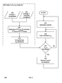
- Figure 3 illustrates a flow chart 300 in accordance with one embodiment of the invention. For clarity of illustration, figure 3 is discussed with references to figures 1 and 2.
- the processor 105 detects whether any applications are executing on the processor 105.
- the processing core 1 110 determines and monitors the C dyn of the processor core 1 110 in step 320.
- the processing core 1 110 compares the C dyn of the processor core 1 110 with the C dyn threshold 116.
- the step 305 of determining the C dyn threshold 116 is performed concurrently with the steps 310, 320, and 330 in one embodiment of the invention.
- the step 305 of determining the C dyn threshold 116 is performed, but not limited to, periodically at a fixed time delay, periodically at a variable or programmable time delay, on demand by the user, and other frequency desired by the user.
- the step 305 of determining the C dyn threshold 116 comprises the steps 350, 355, 360, and 370.
- the processing core 1 110 detects if there is any change in temperature of the processing core 1 350.
- the processing core 1 110 has integrated thermal sensors to determine the temperature of the processing core 1 110.
- the processing core 1 110 provides the temperature information of the processing core 1 110 as the data 118 to the power control unit 150 in one embodiment of the invention.
- the temperature information includes, but is not limited to, the temperature value, the temperature range, indication of a change in temperature, indication of a change in temperature above a threshold, and any other information that facilitates the power control unit 150 to determine the leakage current of the processor 105.
- step 355 the flow checks if there is any change in the operating conditions of the processor 105.
- the step 355 is performed by the ICC protection module 120 in one embodiment of the invention. In another embodiment of the invention, the step 355 is performed by the power control unit 150. In yet another embodiment of the invention, the step 355 is performed by the power control unit 150 and the ICC protection module 120.
- the operating condition of the processor 105 includes, but is not limited to, the performance or operating state (P-state) of the processing core 1 110, the low power modes or state (C-state) of the processing core 1 110, and any other information that affects the leakage current of the processor 105.
- P-state performance or operating state
- C-state low power modes or state
- any other information that affects the leakage current of the processor 105 For example, in one embodiment of the invention, when the operating state or operating point of the processor 105 is changed, the supply voltage to the processor 105 is modified and this in turn impacts the leakage current ICC leakage . In another example, when the processor core 1 110 is in a deep C-state, the supply voltage is removed and this in turn eliminates the leakage current ICC leakage for the processor core 1 110.
- step 360 the power control unit 150 determines the leakage current ICC leakage based on the information from steps 350 and 355.
- the power control unit 150 reallocates the dynamic power supply current ICC dynamic and the leakage current ICC leakage based on the determined leakage current ICC leakage .
- the power control unit 150 reallocates a corresponding decrease or increase in the dynamic power supply current limit ICC dynamic of the processor 105.
- step 370 the power control unit 150 computes or determines the new C dyn threshold 116 and provides the determined C dyn threshold 116 to the ICC protection module 120.
- the step 330 uses the C dyn threshold 116 to compare the current C dyn of the processor 105. If the C dyn of the processor 105 is not greater than the C dyn threshold 116, the flow goes back to step 310. If the C dyn of the processor 105 is greater than the C dyn threshold 116, the ICC protection circuit protects the processor 105 by limiting or reducing the current consumption of the processor 105 in step 340. The flow 300 goes back to step 310 after the current consumption is reduced or limited in step 340.
- the operations illustrated in figure 3 are not meant to be limiting. For clarity of illustration, the flow chart 300 describes only one processing core. One of ordinary skill in the relevant art will readily how the workings of multiple processing cores and shall not be described herein.
- the operations illustrated in figure 3 allow the processor core 1 110 to monitor and control the C dyn of the processor 105.
- the power control unit 150 adjusts the C dyn threshold 116 separately at a slower rate and the temperature of the processor 105 changes slowly. Similarly, the changes in operation conditions of the processor 105 are slower and are under control of the power control unit 150. Hence the power control unit 150 has control over the C dyn threshold 116.
- the power control unit 150 Since the power control unit 150 cannot respond fast enough to limit the dynamically changing C dyn of the application running on the processor, the power control unit 150 provides the C dyn threshold 116 to the processor core 1 110 so that it can control the C dyn of the processor 105 in one embodiment of the invention.
- FIG. 4 illustrates a system or platform 400 to implement the methods disclosed herein in accordance with one embodiment of the invention.
- the system 400 includes, but is not limited to, a desktop computer, a tablet computer, a laptop computer, a netbook, an UltrabookTM, a notebook computer, a personal digital assistant (PDA), a server, a workstation, a cellular telephone, a mobile computing device, a smart phone, an Internet appliance or any other type of computing device.
- the system 400 used to implement the methods disclosed herein may be a system on a chip (SOC) system.
- SOC system on a chip
- the processor 410 has a processing core 412 to execute instructions of the system 400.
- the processing core 412 includes, but is not limited to, fetch logic to fetch instructions, decode logic to decode the instructions, execution logic to execute instructions and the like.
- the processor 410 has a cache memory 416 to cache instructions and/or data of the system 400.
- the cache memory 416 includes, but is not limited to, level one, level two and level three, cache memory or any other configuration of the cache memory within the processor 410.
- the memory control hub (MCH) 414 performs functions that enable the processor 410 to access and communicate with a memory 430 that includes a volatile memory 432 and/or a non-volatile memory 434.
- the volatile memory 432 includes, but is not limited to, Synchronous Dynamic Random Access Memory (SDRAM), Dynamic Random Access Memory (DRAM), RAMBUS Dynamic Random Access Memory (RDRAM), and/or any other type of random access memory device.
- the non-volatile memory 434 includes, but is not limited to, NAND flash memory, phase change memory (PCM), read only memory (ROM), electrically erasable programmable read only memory (EEPROM), or any other type of non-volatile memory device.
- the memory 430 stores information and instructions to be executed by the processor 410.
- the memory 430 may also stores temporary variables or other intermediate information while the processor 410 is executing instructions.
- the chipset 420 connects with the processor 410 via Point-to-Point (PtP) interfaces 417 and 422.
- the chipset 420 enables the processor 410 to connect to other modules in the system 400.
- the chipset 420 is a platform controller hub (PCH) 413.
- the power control unit 150 is integrated in the platform controller hub 420.
- the power control unit 150 is integrated in the processor 410 (not shown in figure 4) but is not part of PCH 413.
- the interfaces 417 and 422 operate in accordance with a PtP communication protocol such as the Intel® QuickPath Interconnect (QPI) or the like.
- the chipset 420 connects to a GPU or a display device 440 that includes, but is not limited to, liquid crystal display (LCD), cathode ray tube (CRT) display, or any other form of visual display device.
- the GPU 440 is not connected to the chipset 420 and is part of the processor 410 (not shown).
- the chipset 420 connects to one or more buses 450 and 460 that interconnect the various modules 474, 480, 482, 484, and 486. Buses 450 and 460 may be interconnected together via a bus bridge 472 if there is a mismatch in bus speed or communication protocol.
- the chipset 420 couples with, but is not limited to, a non-volatile memory 480, a mass storage device(s) 482, a keyboard/mouse 484 and a network interface 486.
- the mass storage device 482 includes, but is not limited to, a solid state drive, a hard disk drive, an universal serial bus flash memory drive, or any other form of computer data storage medium.
- the network interface 486 is implemented using any type of well known network interface standard including, but not limited to, an Ethernet interface, a universal serial bus (USB) interface, a Peripheral Component Interconnect (PCI) Express interface, a wireless interface and/or any other suitable type of interface.
- the wireless interface operates in accordance with, but is not limited to, the IEEE 802.11 standard and its related family, Home Plug AV (HPAV), Ultra Wide Band (UWB), Bluetooth, WiMax, or any form of wireless communication protocol.
- modules shown in figure 4 are depicted as separate blocks within the system 400, the functions performed by some of these blocks may be integrated within a single semiconductor circuit or may be implemented using two or more separate integrated circuits.
- the system 400 may include more than one processor / processing core in another embodiment of the invention.
- operable means that the device, system, protocol etc., is able to operate or is adapted to operate for its desired functionality when the device or system is in off-powered state.
- program code such as instructions, functions, procedures, data structures, logic, application programs, design representations or formats for simulation, emulation, and fabrication of a design, which when accessed by a machine results in the machine performing tasks, defining abstract data types or low-level hardware contexts, or producing a result.
- the techniques shown in the figures can be implemented using code and data stored and executed on one or more computing devices such as general purpose computers or computing devices.
- Such computing devices store and communicate (internally and with other computing devices over a network) code and data using machine-readable media, such as machine readable storage media (e.g., magnetic disks; optical disks; random access memory; read only memory; flash memory devices; phase-change memory) and machine readable communication media (e.g., electrical, optical, acoustical or other form of propagated signals - such as carrier waves, infrared signals, digital signals, etc.).
- machine readable storage media e.g., magnetic disks; optical disks; random access memory; read only memory; flash memory devices; phase-change memory
- machine readable communication media e.g., electrical, optical, acoustical or other form of propagated signals - such as carrier waves, infrared signals, digital signals, etc.
Landscapes
- Engineering & Computer Science (AREA)
- Theoretical Computer Science (AREA)
- Physics & Mathematics (AREA)
- General Engineering & Computer Science (AREA)
- General Physics & Mathematics (AREA)
- Power Sources (AREA)
- Microcomputers (AREA)
Applications Claiming Priority (1)
| Application Number | Priority Date | Filing Date | Title |
|---|---|---|---|
| US13/903,744 US9335813B2 (en) | 2013-05-28 | 2013-05-28 | Method and system for run-time reallocation of leakage current and dynamic power supply current |
Publications (1)
| Publication Number | Publication Date |
|---|---|
| EP2808757A2 true EP2808757A2 (de) | 2014-12-03 |
Family
ID=50624446
Family Applications (1)
| Application Number | Title | Priority Date | Filing Date |
|---|---|---|---|
| EP14165888.0A Withdrawn EP2808757A2 (de) | 2013-05-28 | 2014-04-24 | Verfahren und System zur Umverteilung von Leckstrom und dynamischem Netzteilstrom |
Country Status (2)
| Country | Link |
|---|---|
| US (1) | US9335813B2 (de) |
| EP (1) | EP2808757A2 (de) |
Cited By (1)
| Publication number | Priority date | Publication date | Assignee | Title |
|---|---|---|---|---|
| US11041892B2 (en) | 2017-12-22 | 2021-06-22 | Renesas Electronics Corporation | Semiconductor device, semiconductor system, and control method of the same |
Families Citing this family (11)
| Publication number | Priority date | Publication date | Assignee | Title |
|---|---|---|---|---|
| US10108454B2 (en) * | 2014-03-21 | 2018-10-23 | Intel Corporation | Managing dynamic capacitance using code scheduling |
| US9477243B2 (en) | 2014-12-22 | 2016-10-25 | Intel Corporation | System maximum current protection |
| CN105068872B (zh) * | 2015-07-28 | 2018-11-23 | 深圳市万普拉斯科技有限公司 | 运算单元的控制方法和系统 |
| US9952651B2 (en) * | 2015-07-31 | 2018-04-24 | International Business Machines Corporation | Deterministic current based frequency optimization of processor chip |
| US9568982B1 (en) | 2015-07-31 | 2017-02-14 | International Business Machines Corporation | Management of core power state transition in a microprocessor |
| US10268255B2 (en) * | 2016-06-29 | 2019-04-23 | Intel Corporation | Management of system current constraints with current limits for individual engines |
| US10234920B2 (en) * | 2016-08-31 | 2019-03-19 | Intel Corporation | Controlling current consumption of a processor based at least in part on platform capacitance |
| KR102663815B1 (ko) * | 2018-06-01 | 2024-05-07 | 삼성전자주식회사 | 컴퓨팅 장치 및 이의 동작 방법 |
| KR102704694B1 (ko) * | 2019-08-13 | 2024-09-10 | 삼성전자주식회사 | 신뢰성 향상을 위한 스토리지 장치의 구동 방법 및 이를 수행하는 스토리지 장치 |
| US11703927B2 (en) * | 2020-03-27 | 2023-07-18 | Intel Corporation | Leakage degradation control and measurement |
| US11556342B1 (en) * | 2020-09-24 | 2023-01-17 | Amazon Technologies, Inc. | Configurable delay insertion in compiled instructions |
Family Cites Families (5)
| Publication number | Priority date | Publication date | Assignee | Title |
|---|---|---|---|---|
| US7117114B2 (en) * | 2004-08-23 | 2006-10-03 | Intel Corporation | On-die temperature control data for communicating to a thermal actuator |
| US7711966B2 (en) * | 2004-08-31 | 2010-05-04 | Qualcomm Incorporated | Dynamic clock frequency adjustment based on processor load |
| US7900069B2 (en) * | 2007-03-29 | 2011-03-01 | Intel Corporation | Dynamic power reduction |
| US9069555B2 (en) * | 2011-03-21 | 2015-06-30 | Intel Corporation | Managing power consumption in a multi-core processor |
| US20140237272A1 (en) * | 2013-02-19 | 2014-08-21 | Advanced Micro Devices, Inc. | Power control for data processor |
-
2013
- 2013-05-28 US US13/903,744 patent/US9335813B2/en not_active Expired - Fee Related
-
2014
- 2014-04-24 EP EP14165888.0A patent/EP2808757A2/de not_active Withdrawn
Non-Patent Citations (1)
| Title |
|---|
| None |
Cited By (2)
| Publication number | Priority date | Publication date | Assignee | Title |
|---|---|---|---|---|
| US11041892B2 (en) | 2017-12-22 | 2021-06-22 | Renesas Electronics Corporation | Semiconductor device, semiconductor system, and control method of the same |
| EP3502892B1 (de) * | 2017-12-22 | 2021-09-08 | Renesas Electronics Corporation | Halbleiterbauelement, halbleitersystem und steuerungsverfahren dafür |
Also Published As
| Publication number | Publication date |
|---|---|
| US9335813B2 (en) | 2016-05-10 |
| US20140359328A1 (en) | 2014-12-04 |
Similar Documents
| Publication | Publication Date | Title |
|---|---|---|
| US9335813B2 (en) | Method and system for run-time reallocation of leakage current and dynamic power supply current | |
| US9436254B2 (en) | Method and apparatus for per core performance states | |
| US9026816B2 (en) | Method and system for determining an energy-efficient operating point of a platform | |
| US9235252B2 (en) | Dynamic balancing of power across a plurality of processor domains according to power policy control bias | |
| US9671854B2 (en) | Controlling configurable peak performance limits of a processor | |
| US9158351B2 (en) | Dynamic power limit sharing in a platform | |
| US9335803B2 (en) | Calculating a dynamically changeable maximum operating voltage value for a processor based on a different polynomial equation using a set of coefficient values and a number of current active cores | |
| US9377841B2 (en) | Adaptively limiting a maximum operating frequency in a multicore processor | |
| US8862918B2 (en) | Efficient frequency boost operation | |
| US20160252942A1 (en) | Supercapacitor-based power supply protection for multi-node systems | |
| US9501299B2 (en) | Minimizing performance loss on workloads that exhibit frequent core wake-up activity | |
| CN103262000A (zh) | Vr功率模式接口 | |
| CN104798002B (zh) | 在处理器中实施功率消耗占空比 |
Legal Events
| Date | Code | Title | Description |
|---|---|---|---|
| PUAI | Public reference made under article 153(3) epc to a published international application that has entered the european phase |
Free format text: ORIGINAL CODE: 0009012 |
|
| 17P | Request for examination filed |
Effective date: 20140424 |
|
| AK | Designated contracting states |
Kind code of ref document: A2 Designated state(s): AL AT BE BG CH CY CZ DE DK EE ES FI FR GB GR HR HU IE IS IT LI LT LU LV MC MK MT NL NO PL PT RO RS SE SI SK SM TR |
|
| AX | Request for extension of the european patent |
Extension state: BA ME |
|
| STAA | Information on the status of an ep patent application or granted ep patent |
Free format text: STATUS: THE APPLICATION IS DEEMED TO BE WITHDRAWN |
|
| 18D | Application deemed to be withdrawn |
Effective date: 20161101 |