EP2808624A1 - Wärmepumpenvorrichtung - Google Patents
Wärmepumpenvorrichtung Download PDFInfo
- Publication number
- EP2808624A1 EP2808624A1 EP13002803.8A EP13002803A EP2808624A1 EP 2808624 A1 EP2808624 A1 EP 2808624A1 EP 13002803 A EP13002803 A EP 13002803A EP 2808624 A1 EP2808624 A1 EP 2808624A1
- Authority
- EP
- European Patent Office
- Prior art keywords
- power electronics
- heat exchanger
- heat pump
- channel
- tubes
- Prior art date
- Legal status (The legal status is an assumption and is not a legal conclusion. Google has not performed a legal analysis and makes no representation as to the accuracy of the status listed.)
- Granted
Links
Images



Classifications
-
- F—MECHANICAL ENGINEERING; LIGHTING; HEATING; WEAPONS; BLASTING
- F25—REFRIGERATION OR COOLING; COMBINED HEATING AND REFRIGERATION SYSTEMS; HEAT PUMP SYSTEMS; MANUFACTURE OR STORAGE OF ICE; LIQUEFACTION SOLIDIFICATION OF GASES
- F25B—REFRIGERATION MACHINES, PLANTS OR SYSTEMS; COMBINED HEATING AND REFRIGERATION SYSTEMS; HEAT PUMP SYSTEMS
- F25B30/00—Heat pumps
- F25B30/02—Heat pumps of the compression type
-
- F—MECHANICAL ENGINEERING; LIGHTING; HEATING; WEAPONS; BLASTING
- F25—REFRIGERATION OR COOLING; COMBINED HEATING AND REFRIGERATION SYSTEMS; HEAT PUMP SYSTEMS; MANUFACTURE OR STORAGE OF ICE; LIQUEFACTION SOLIDIFICATION OF GASES
- F25B—REFRIGERATION MACHINES, PLANTS OR SYSTEMS; COMBINED HEATING AND REFRIGERATION SYSTEMS; HEAT PUMP SYSTEMS
- F25B2600/00—Control issues
- F25B2600/02—Compressor control
- F25B2600/025—Compressor control by controlling speed
-
- F—MECHANICAL ENGINEERING; LIGHTING; HEATING; WEAPONS; BLASTING
- F25—REFRIGERATION OR COOLING; COMBINED HEATING AND REFRIGERATION SYSTEMS; HEAT PUMP SYSTEMS; MANUFACTURE OR STORAGE OF ICE; LIQUEFACTION SOLIDIFICATION OF GASES
- F25B—REFRIGERATION MACHINES, PLANTS OR SYSTEMS; COMBINED HEATING AND REFRIGERATION SYSTEMS; HEAT PUMP SYSTEMS
- F25B2700/00—Sensing or detecting of parameters; Sensors therefor
- F25B2700/21—Temperatures
- F25B2700/2115—Temperatures of a compressor or the drive means therefor
- F25B2700/21153—Temperatures of a compressor or the drive means therefor of electronic components
Definitions
- Heat pumps have a refrigeration cycle with a compressor, a condenser, an expansion valve and an evaporator.
- the heat pumps serve, for example, the heating of heating water.
- the heat of the heat pump is provided by condensation of refrigerant under high pressure and at high temperature and can be delivered, for example, to heating water or service water.
- the liquefied refrigerant is then expanded in a throttle body (expansion valve) and evaporated while absorbing ambient heat in the evaporator of the heat pump.
- the refrigerant vapor is compressed in the compressor and the refrigerant can be re-liquefied in the condenser.
- the compressors of the heat pumps can be designed speed-controlled to adjust the speed of the compressor to the required heating power. This is advantageous in terms of improved efficiency.
- a heat pump apparatus having a refrigeration cycle including an evaporator, a variable speed compressor, a condenser having a port for a heating and / or process water system, an expansion valve, and a power electronics unit for controlling the speed of the compressor.
- the heat pump device also has a power electronics heat exchanger for cooling the power electronics unit.
- the power electronics heat exchanger has an inlet channel and an outlet channel and a plurality of connecting tubes between the inlet channel and the outlet channel.
- the power electronics unit is coupled to the connecting pipes for cooling.
- the power electronics heat exchanger is coupled to the connection for the heating and / or service water system so that a heat transfer medium flowing through the heating water and / or service water system can flow through the cooling unit for cooling the power electronics unit.
- the power electronics heat exchanger can be coupled to a return of the heating water and / or service water system, so that the heat transfer medium flowing back from the return of the heating water and / or service water system can be used to cool the power electronics.
- the diameter of the inlet channel and the outlet channel is twice as large as the internal diameter of the connecting tubes.
- the connecting tubes have a circular cross section on the inside and at least one flat section on the outside. This is advantageous because thus the outer planar portion can be coupled to a power electronics unit for cooling the power electronics unit.
- the connecting tubes of the power electronics heat exchanger are soldered, welded or glued to the inlet or outlet channel.
- the inlet channel and the outlet channel have stops which project into the connecting tubes.
- the invention relates to the idea to provide a heat pump unit with a refrigerant circuit, with a throttle body, a compressor and an evaporator, wherein the compressor or its speed can be controlled by a power electronics unit.
- the power electronics unit is used in particular to control the speed of the compressor.
- a speed-controllable compressor is particularly advantageous in terms of greater efficiency, since the heating power can be adapted to the actual needs.
- the power electronics unit generates heat loss, which can be dissipated by means of a heat exchanger.
- the heat pump unit can optionally be connected to a service water or a heating water system. For this purpose, the heat pump unit to an inlet and a return.
- a heat exchanger is provided on the heating return, which transfers the heat loss of the power electronics unit to the heat transfer medium flowing through the heat transfer medium (heating water).
- the provision of the heat exchanger in the return of the service water and / or Walkerwassersystems is advantageous because the heat sink in the heating operation of the heat pump is lower, and thus the dissipated performance is higher. If the heat pump unit is a reversible heat pump unit, then the heat transfer medium in the heat exchanger is warmer, since the heat pump unit is in cooling mode, and a dewing of the electronics is thereby lower.
- a first connection is provided on an inlet channel, which is arranged in particular offset relative to a second connection of the outlet channel, so that the heat transfer medium flows through the tubes during operation of the heat pump with substantially uniform volume flows.
- the heat pump device comprises a cooling circuit with an evaporator, a variable speed compressor, a condenser, a connection for a heating and / or process water system, an expansion valve and a power electronics unit LE for controlling the speed of the compressor.
- Fig. 1 shows a schematic representation of a portion of a heat pump according to the first embodiment.
- a first power electronics heat exchanger and a second heat exchanger HZ for a heating water system and / or a service water system is shown.
- the first power electronics heat exchanger WT is coupled to a power electronics unit LE to cool them.
- the power electronics unit LE is coupled to a compressor (not shown) and controls the speed of the compressor.
- the heat loss generated by the modules of the power electronics unit is dissipated via the first power electronics heat exchanger WT.
- the input of the power electronics heat exchanger WT is coupled to the return RL of the heating water and / or service water unit.
- the heat pump device has a connection for the heating and / or service water unit.
- the heat transfer medium which has flowed through the heating water unit and has given off its heat there to the heat transfer medium is supplied to the first power electronics heat exchanger WT and flows through this power electronics heat exchanger WT and absorbs the heat loss of the power electronics unit LE. This can lead to a heating of the heat transfer medium return of z. B. lead 0.5 ° C.
- Fig. 2A shows a schematic representation of a heat exchanger according to the first embodiment.
- the first power electronics heat exchanger WT for the power electronics unit LE has two substantially parallel channels WT10 and WT20, wherein the two channels WT10 and WT20 are coupled together by a plurality of tubes WT30.
- the heat transfer medium can flow from the return RL of the heating water system in the first channel WT10 and from there through the tubes WT30 in the second channel WT20.
- the tubes WT30 are preferably in the inner diameter round and outside at least on one side smooth or the tubes are rectangular outside or angular designed.
- the rectangular or smooth outer shape of the tubes is advantageous because there a cooling surface for the power electronics unit LE can be provided and it can thus come to a good heat transfer.
- the number of tubes WT30 is determined by the on-resistance and the area required for the cooling of the power electronics unit LE.
- Fig. 2B shows a schematic sectional view of a part of the heat exchanger of Fig. 2A , In Fig. 2B In particular, the transition between the channels WT10, WT20 and the tubes WT30 is shown.
- the transition between the first and second channels WT10, WT20 is achieved according to the invention by an extraction WT21 of the channels WT10, WT20.
- the tubes WT30 can then be pushed onto the neck WT21 and can be subsequently bent, for example.
- Figure 2c shows the flow situation in the first power electronics heat exchanger WT, as the heat transfer medium flows through the power electronics heat exchanger WT.
- the first power electronics heat exchanger WT preferably has a first connection A1, with which the first power electronics heat exchanger WT can advantageously be connected to the heating and / or service water unit and during operation of the heat pump, an inflow of the heat transfer medium preferably from the return to the first Power electronics heat exchanger WT takes place.
- the inflow S is divided into a number of flows S1 to S6 in the first channel WT10.
- the flows S1 to S6 flow through the pipes WT30 to the second channel WT20, where they flow out as the flow S 'from the first power electronics heat exchanger WT, in particular through a second connection A2.
- the inflow S takes place on the same side as the outflow S '.
- the flow resistance in the illustrated heat exchanger WT10 according to Figure 2c is lowest for the flow S1.
- the tubes WT30 in the pipe diameter can in particular be adapted or corresponding diaphragms in the pipes WT30 be introduced or even the first channel WT10 and / or the second channel WT20 are adapted in their flow cross-section so that form equal partial flows S1 to S6 and partial flows S'1 and S'6.
- Fig. 3 shows a schematic view of a power electronics unit and their cooling according to a second embodiment.
- a cooling plate KP may be provided on the channels WT30 of the first power electronics heat exchanger WT.
- the portion of the channels WT30, which is opposite to the cooling plate KP, is preferably planar, so that good heat transfer between the tubes WT30 and the cooling plate KP can occur.
- the elements of the power electronics unit LE can be provided on the cooling plate KP, so that the power electronics units LE can be cooled by the cooling plate KP and the tubes WT30.
- the tubes WT30 preferably have a circular cross-section on the inside and can have a flat section on the outside, at least on one side. Furthermore, the tubes WT30 can be made rectangular in cross-section.
- a heat pump unit is provided with an evaporator, a variable speed compressor, a condenser, an expansion valve and a power electronics unit for driving the speed of the compressor.
- the heat pump also has a power electronics heat exchanger.
- the power electronics heat exchanger has an inlet, a drain and a plurality of tubes between the inlet and the outlet.
- the cooling medium then flows through the inlet and the pipes to the drain.
- the tubes have a rectangular outside and inside a round cross section.
- the outside of the tubes is in direct communication with a surface of the power electronics unit to be cooled.
- the pipe diameter of the inlet channel and the outlet channel is more than twice as large as the inner diameter of the tubes.
- the inlet channel and the outlet channel have an inner diameter between 10 and 40 mm, and the inner diameter of the connecting tubes is between 5 and 20 mm.
- connecting pipes between 3 to 10 connecting pipes are provided between the inlet channel and the outlet channel.
- the connecting pipes can be soldered, welded or glued to the inlet and outlet channel.
- the inlet channel and the outlet channel have necked portions which can project into the connecting tubes.
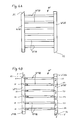
- FIG. 4 a shows a first power electronics heat exchanger WT, in which the first port A1 lies in particular diagonally opposite or diagonally to the second port A2.
- a largely uniform flow of the partial streams S1 to S6 takes place during operation of the heat pump.
- the flow resistance for the branching flow S1 is the lowest. This flows through the pipe WT30 and flows into the pipe WT20 at a closed end WT20 A, where the flow resistance is then greater than in the sub-streams S'2 to S'6.
- the currents S1 to S6 are uniformed.
- the first port A1 is provided for the inflow S of the heat transfer medium.
- the partial flow S1 flows through a tube WT30 to the second channel WT20, which advantageously has no connection at this point, but a termination WT20 A.
- a termination WT20 A In contrast to the embodiment, as in Figure 2c is shown opposite to a first port A1, in the following flow direction S1 through the pipe WT30 to the second channel WT20 a WT20A completion, before.
- the flow of the heat transfer medium takes place through the second connection A2, which lies downstream of the flow S'6 in the flow direction.
- On the side of the first channel WT10 is preferably located in the region of the flow S6 a conclusion WT10 A.
- FIG. 5 a further embodiment is shown, wherein the first port A1 takes place laterally into the first channel WT10.
- the first port A1 is located between two pipes WT30.
- the second connection for the flow S 'of the heat transfer medium is arranged between two tubes WT30 laterally on the second channel WT20. Also by this arrangement, the homogenization of the partial streams S1 to S6 is made possible, since the flow resistances cancel each other, in particular by the staggered arrangement of the first terminal A1 and the second terminal A2.
- the first channel WT10 and the second channel WT20 each have a termination WT10A, and WT20A.
- This conclusion can also be used as a pipe bend, as it is in FIG. 5 is shown, in particular in the region of the second terminal A2.
- no flow from the first power electronics heat exchanger WT is provided at the terminations WT10 A and WT 20 A.
- at least one termination WT 10 A and / or WT 20 A is formed by a shut-off device, so that the shut-off at the terminations WT10 A or WT 20 A through a flap valve, check valve or similar device.
- At least a partial flow of the heat transfer medium flow according to an idea of the invention from the heat exchanger through the barrier when it is opened, such as for maintenance or if in defined operating conditions of the heat pump opening of the barrier is provided by at least a partial flow over the then open Barrier should take place.
- the z. B be required to flow through certain areas more or less strongly with heat transfer medium. This is advantageously carried out as a function of the load on the power electronics unit, in particular if different partitions of the power electronics unit are loaded.
Landscapes
- Engineering & Computer Science (AREA)
- Physics & Mathematics (AREA)
- Mechanical Engineering (AREA)
- Thermal Sciences (AREA)
- General Engineering & Computer Science (AREA)
- Heat-Exchange Devices With Radiators And Conduit Assemblies (AREA)
- Compression-Type Refrigeration Machines With Reversible Cycles (AREA)
Abstract
Description
- Wärmepumpen weisen einen Kältekreislauf mit einem Verdichter, einem Verflüssiger, einem Expansionsventil und einem Verdampfer auf. Die Wärmepumpen dienen beispielsweise der Erwärmung von Heizungswasser. Hierbei wird die Heizwärme der Wärmepumpe durch Kondensation von Kältemittel unter hohem Druck und bei hoher Temperatur bereitgestellt und kann beispielsweise an Heizungswasser oder Brauchwasser abgegeben werden. Das verflüssigte Kältemittel wird dann in einem Drosselorgan (Expansionsventil) entspannt und verdampft unter Aufnahme von Umgebungswärme im Verdampfer der Wärmepumpe. Der Kältemitteldampf wird in dem Verdichter komprimiert, und das Kältemittel kann im Kondensator wieder verflüssigt werden.
- Die Verdichter der Wärmepumpen können drehzahlgeregelt ausgestaltet sein, um die Drehzahl des Verdichters an die benötige Heizleistung anzupassen. Dies ist vorteilhaft im Hinblick auf die verbesserte Effizienz.
- Es ist eine Aufgabe der vorliegenden Erfindung, die bekannten Wärmepumpeneinheiten mit drehzahlgeregelten Verdichtern zu verbessern.
- Diese Aufgabe wird durch eine Wärmepumpenvorrichtung nach Anspruch 1 gelöst.
- Somit wird eine Wärmepumpenvorrichtung mit einem Kühlkreislauf mit einem Verdampfer, einem drehzahlregelbaren Verdichter, einem Verflüssiger, der einen Anschluss für ein Heizungs- und/oder Brauchwassersystem aufweist, einem Expansionsventil und einer Leistungselektronik-Einheit zum Steuern der Drehzahl des Verdichters vorgesehen. Die Wärmepumpenvorrichtung weist ebenfalls einen Leistungselektronik-Wärmeübertrager zum Kühlen der Leistungselektronik-Einheit auf. Der Leistungselektronik-Wärmeübertrager weist einen Zulaufkanal und einen Ablaufkanal sowie eine Mehrzahl von Verbindungsrohren zwischen dem Zulaufkanal und dem Ablaufkanal auf. Die Leistungselektronik-Einheit ist zur Kühlung mit den Verbindungsrohren gekoppelt. Der Leistungselektronik-Wärmeübertrager ist mit dem Anschluss für das Heizungs- und/oder Brauchwassersystem gekoppelt, so dass ein durch das Heizungswasser- und/oder Brauchwassersystem fließendes Wärmeträgermedium durch die Kühleinheit zur Kühlung der Leistungselektronik-Einheit fließen kann.
- Gemäß einem Aspekt der vorliegenden Erfindung ist der Leistungselektronik-Wärmeübertrager an einen Rücklauf des Heizungswasser- und/oder Brauchwassersystems koppelbar, so dass das aus dem Rücklauf des Heizungswasser-und/oder Brauchwassersystems zurückfließende Wärmeträgermedium zur Kühlung der Leistungselektronik verwendet werden kann.
- Gemäß einem Aspekt der vorliegenden Erfindung ist der Durchmesser des Zulaufkanals und des Ablaufkanals doppelt so groß wie der Innendurchmesser der Verbindungsrohre.
- Gemäß einem weiteren Aspekt der vorliegenden Erfindung weisen die Verbindungsrohre innen einen kreisförmigen Querschnitt und außen zumindest einen ebenen Abschnitt auf. Dies ist vorteilhaft, weil somit der äußere ebene Abschnitt mit einer Leistungselektronik-Einheit zur Kühlung der Leistungselektronik-Einheit gekoppelt werden kann.
- Gemäß einem weiteren Aspekt der vorliegenden Erfindung werden die Verbindungsrohre des Leistungselektronik-Wärmeübertragers an dem Zulauf- oder Ablaufkanal verlötet, verschweißt oder verklebt.
- Gemäß einem weiteren Aspekt der vorliegenden Erfindung weisen der Zulaufkanal und der Ablaufkanal Aufhalsungen auf, welche in die Verbindungsrohre hinein ragen.
- Die Erfindung betrifft den Gedanken, eine Wärmepumpeneinheit mit einem Kältemittelkreislauf, mit einem Drosselorgan, einem Verdichter und einem Verdampfer vorzusehen, wobei der Verdichter bzw. seine Drehzahl über eine Leistungselektronik-Einheit gesteuert werden kann. Die Leistungselektronik-Einheit dient insbesondere dazu, die Drehzahl des Verdichters zu steuern. Ein drehzahlregelbarer Verdichter ist insbesondere vorteilhaft im Hinblick auf eine größere Effizienz, da die Heizleistung an den tatsächlichen Bedarf angepasst werden kann. Die Leistungselektronik-Einheit erzeugt Verlustwärme, welche mittels eines Wärmeübertragers abgeführt werden kann. Die Wärmepumpeneinheit kann optional an ein Brauchwasser- oder ein Heizungswassersystem angeschlossen werden. Dazu weist die Wärmepumpeneinheit einen Zulauf und einen Rücklauf auf. Gemäß der Erfindung wird an dem Heizungsrücklauf ein Wärmeübertrager vorgesehen, welcher die Verlustwärme der Leistungselektronik-Einheit an das durch den Wärmeübertrager fließende Wärmeträgermedium (Heizungswasser) überträgt.
- Das Vorsehen des Wärmeübertragers in dem Rücklauf des Brauchwasser-und/oder Heizwassersystems ist vorteilhaft, weil die Wärmesenke im Heizbetrieb der Wärmepumpe niedriger, und somit die abführbare Leistung höher ist. Falls es sich bei der Wärmepumpeneinheit um eine reversible Wärmepumpeneinheit handelt, dann ist das Wärmeträgermedium in dem Wärmeübertrager wärmer, da die Wärmepumpeneinheit sich im Kühlbetrieb befindet, und eine Betauung der Elektronik ist dadurch geringer.
- Vorteilhaft ist an einem Zulaufkanal ein erster Anschluss vorgesehen, der insbesondere versetzt zu einem zweiten Anschluss des Ablaufkanals angeordnet ist, so dass das Wärmeträgermedium im Betrieb der Wärmepumpe mit weitgehend gleichmäßigen Volumenströmen durch die Rohre strömt.
- Weitere Aspekte der Erfindung sind Gegenstand der Unteransprüche.
- Vorteile und Ausführungsbeispiele der Erfindung werden nachstehend unter Bezugnahme auf die Zeichnung näher erläutert.
- Fig. 1
- zeigt eine schematische Darstellung eines Teils einer Wärmepumpe gemäß dem ersten Ausführungsbeispiel,
- Fig. 2A
- zeigt eine schematische Darstellung eines Wärmeübertragers gemäß dem ersten Ausführungsbeispiel,
- Fig. 2B
- zeigt eine schematische Schnittansicht eines Teils des Wärmeübertragers von
Fig. 2A , - Fig. 2C
- zeigt einen Wärmeübertrager mit Darstellung einer Strömung im Betrieb der Wärmepumpe,
- Fig. 3
- zeigt eine schematische Ansicht einer Leistungselektronik-Einheit und ihrer Kühlung gemäß einem zweiten Ausführungsbeispiel,
- Fig. 4A
- zeigt einen Wärmeübertrager mit versetztem Ein- und Auslauf,
- Fig. 4B
- zeigt eine Darstellung eines Strömungsverlaufs und
- Fig. 5
- zeigt einen Anschluss zwischen zwei Rohren.
- Gemäß der Erfindung weist die Wärmepumpenvorrichtung einen Kühlkreislauf mit einem Verdampfer, einen drehzahlregelbaren Verdichter, einen Verflüssiger, der einen Anschluss für ein Heizungs- und/oder Brauchwassersystem aufweist, ein Expansionsventil und eine Leistungselektronik-Einheit LE zum Steuern der Drehzahl des Verdichters auf.
-
Fig. 1 zeigt eine schematische Darstellung eines Teils einer Wärmepumpe gemäß dem ersten Ausführungsbeispiel. InFig. 1 ist eine erster Leistungselektronik-Wärmeübertrager und ein zweiter Wärmeübertrager HZ für eine Heizungswasseranlage und/oder eine Brauchwasseranlage gezeigt. Der erste Leistungselektronik-Wärmeübertrager WT ist mit einer Leistungselektronik-Einheit LE gekoppelt, um diese zu kühlen. Die Leistungselektronik-Einheit LE ist mit einem (nicht gezeigten) Verdichter gekoppelt und regelt die Drehzahl des Verdichters. Die durch die Baugruppen der Leistungselektronik-Einheit entstehende Verlustwärme wird über den ersten Leistungselektronik-Wärmeübertrager WT abgeführt. Gemäß einem ersten Ausführungsbeispiel ist der Eingang des Leistungselektronik-Wärmeübertragers WT an den Rücklauf RL der Heizungswasser- und/oder Brauchwassereinheit gekoppelt. Damit weist die Wärmepumpenvorrichtung einen Anschluss für die Heizungs- und/oder Brauchwassereinheit auf. Mit anderen Worten, das Wärmeübertragungsmedium, welches die Heizungswassereinheit durchflossen hat und seine Wärme dort an das Wärmeträgermedium abgegeben hat, wird dem ersten Leistungselektronik-Wärmeübertrager WT zugeführt und fließt durch diesen Leistungselektronik-Wärmeübertrager WT und nimmt die Verlustwärme der Leistungselektronik-Einheit LE auf. Dies kann zu einer Erwärmung des Wärmeträgermedium-Rücklaufs von z. B. 0,5°C führen. -
Fig. 2A zeigt eine schematische Darstellung eines Wärmeübertragers gemäß dem ersten Ausführungsbeispiel. Der erste Leistungselektronik-Wärmeübertrager WT für die Leistungselektronik-Einheit LE weist zwei im Wesentlichen parallele Kanäle WT10 und WT20 auf, wobei die beiden Kanäle WT10 und WT20 durch eine Vielzahl von Rohren WT30 miteinander gekoppelt sind. Somit kann das Wärmeträgermedium aus dem Rücklauf RL des Heizungswassersystems in den ersten Kanal WT10 und von dort durch die Rohre WT30 in den zweiten Kanal WT20 fließen. Die Rohre WT30 sind vorzugweise im Innendurchmesser rund und außen zumindest an einer Seite glatt bzw. die Rohre sind außen rechteckig bzw. eckig ausgestaltet. Die rechteckige bzw. glatte Außenform der Rohre ist vorteilhaft, weil dort eine Kühlfläche für die Leistungselektronik-Einheit LE vorgesehen werden kann und es damit zu einer guten Wärmeübertragung kommen kann. Die Anzahl der Rohre WT30 wird durch den Durchlasswiderstand und die benötigte Fläche für die Kühlung der Leistungselektronik-Einheit LE bestimmt. -
Fig. 2B zeigt eine schematische Schnittansicht eines Teils des Wärmeübertragers vonFig. 2A . InFig. 2B ist insbesondere der Übergang zwischen den Kanälen WT10, WT20 und den Rohren WT30 gezeigt. Der Übergang zwischen dem ersten und zweiten Kanal WT10, WT20 wird gemäß der Erfindung durch eine Aushalsung WT21 der Kanäle WT10, WT20 erreicht. Die Rohre WT30 können dann auf die Aushalsung WT21 aufgeschoben werden und können beispielsweise anschließend gekröpft werden. -
Figur 2c zeigt die Strömungssituation im ersten Leistungselektronik-Wärmeübertrager WT, wie das Wärmeübertragungsmedium durch den Leistungselektronik-Wärmeübertrager WT fließt. Hierzu weist der erste Leistungselektronik-Wärmeübertrager WT vorzugsweise einen ersten Anschluss A1 auf, mit dem der erste Leistungselektronik-Wärmeübertrager WT vorteilhaft an die Heizungs- und/oder Brauchwassereinheit angeschlossen werden kann und im Betrieb der Wärmepumpe ein Zustrom des Wärmeübertragungsmediums vorzugsweise aus dem Rücklauf zum ersten Leistungselektronik-Wärmeübertrager WT erfolgt. Der Zustrom S teilt sich im ersten Kanal WT10 in eine Anzahl von Strömungen S1 bis S6 auf. Die Strömungen S1 bis S6 strömen durch die Rohre WT30 zum zweiten Kanal WT20, wo sie als Fortstrom S' aus dem ersten Leistungselektronik-Wärmeübertrager WT, insbesondere durch einen zweiten Anschluss A2 wieder herausfließen. Gemäß dem Beispiel beiFigur 2c erfolgt die Zuströmung S auf der gleichen Seite wie der Fortstrom S'. Der Strömungswiderstand im gezeigten Wärmeaustauscher WT10 gemäßFigur 2c ist für die Strömung S1 am geringsten. Um zu erreichen, dass die Strömungen S1 bis S6 möglichst gleich sind, bzw. eine möglichst gleiche Volumenstromverteilung auf die Teilströme S1 bis S6 erfolgt, können die Rohre WT30 im Rohrdurchmesser insbesondere angepasst werden oder entsprechende Blenden in den Rohren WT30 eingebracht sein oder aber auch der erste Kanal WT10 und/oder der zweite Kanal WT20 in ihrem Strömungsquerschnitt so angepasst werden, dass sich gleiche Teilströme S1 bis S6 und Teilströme S'1 und S'6 bilden. -
Fig. 3 zeigt eine schematische Ansicht einer Leistungselektronik-Einheit und ihrer Kühlung gemäß einem zweiten Ausführungsbeispiel. Eine Kühlplatte KP kann auf den Kanälen WT30 des ersten Leistungselektronik-Wärmeübertragers WT vorgesehen sein. Derjenige Abschnitt der Kanäle WT30, der der Kühlplatte KP gegenüber liegt, ist vorzugsweise eben ausgestaltet, damit es zu einer guten Wärmeübertragung zwischen den Rohren WT30 und der Kühlplatte KP kommen kann. Die Elemente der Leistungselektronik-Einheit LE können auf der Kühlplatte KP vorgesehen sein, so dass die Leistungselektronik-Einheiten LE durch die Kühlplatte KP und die Rohre WT30 gekühlt werden können. - Die Rohre WT30 weisen innen vorzugsweise einen kreisförmigen Querschnitt auf und können außen zumindest an einer Seite einen ebenen Abschnitt aufweisen. Ferner können die Rohre WT30 im Querschnitt rechteckig ausgestaltet sein.
- Gemäß der Erfindung wird eine Wärmepumpeneinheit mit einem Verdampfer, einem drehzahlregelbaren Verdichter, einem Verflüssiger, einem Expansionsventil und einer Leistungselektronik-Einheit zum Ansteuern der Drehzahl des Verdichters vorgesehen. Die Wärmepumpe weist ferner einen Leistungselektronik-Wärmeübertrager auf. Der Leistungselektronik-Wärmeübertrager weist einen Zulauf, einen Ablauf sowie mehrere Rohre zwischen dem Zulauf und dem Ablauf auf. Das Kühlmedium fließt dann durch den Zulauf und die Rohre zu dem Ablauf. Vorzugsweise weisen die Rohre außen einen rechteckigen und innen einen runden Querschnitt auf. Die Außenseite der Rohre steht in direkter Verbindung mit einer zu kühlenden Fläche der Leistungselektronik-Einheit. Optional ist der Rohrdurchmesser des Zulaufkanals und des Ablaufkanals mehr als doppelt so groß wie der Innendurchmesser der Rohre.
- Gemäß einem Aspekt der Erfindung weist der Zulaufkanal und der Ablaufkanal einen Innendurchmesser zwischen 10 und 40 mm auf, und der Innendurchmesser der Verbindungsrohre liegt zwischen 5 und 20 mm.
- Gemäß einem Aspekt der vorliegenden Erfindung sind zwischen 3 bis 10 Verbindungsrohre zwischen dem Zulaufkanal und dem Ablaufkanal vorgesehen. Die Verbindungsrohre können mit dem Zulauf- und Ablaufkanal verlötet, verschweißt oder verklebt sein.
- Gemäß einem weiteren Aspekt der vorliegenden Erfindung weisen der Zulaufkanal und der Ablaufkanal Aushalsungen auf, welche in die Verbindungsrohre hineinragen können.
-
Figur 4 a zeigt einen ersten Leistungselektronik-Wärmeübertrager WT, bei dem der erste Anschluss A1 insbesondere schräg gegenüber oder diagonal zum zweiten Anschluss A2 liegt. Somit erfolgt eine weitgehend vergleichmäßigte Strömung der Teilströme S1 bis S6 im Betrieb der Wärmepumpe. Im Rohr WT10 ist zunächst der Strömungswiderstand für die abzweigende Strömung S1 am geringsten. Diese durchströmt das Rohr WT30 und strömt in das Rohr WT20 an einem geschlossenen Ende WT20 A, wo der Strömungswiederstand dann größer als bei den Teilströmen S'2 bis S'6 ist. Somit sind die Ströme S1 bis S6 vergleichmäßigt. - Gemäß
Figur 4b ist der erste Anschluss A1 für den Zustrom S des Wärmeübertragungsmediums vorgesehen. Der Teilstrom S1 fließt durch ein Rohr WT30 zum zweiten Kanal WT20, der in vorteilhafter Weise an dieser Stelle keinen Anschluss aufweist, sondern einen Abschluss WT20 A. Im Unterschied zur Ausführung, wie sie inFigur 2c gezeigt ist, liegt gegenüber einem ersten Anschluss A1, auf die folgende Strömungsrichtung S1 durch das Rohr WT30 zum zweiten Kanal WT20 ein Abschluss WT20A, vor. Der Fortstrom des Wärmeübertragungsmediums erfolgt durch den zweiten Anschluss A2, der in Strömungsrichtung hinter dem Strom S'6 liegt. Auf der Seite des ersten Kanals WT10 befindet sich vorzugsweise im Bereich der Strömung S6 ein Abschluss WT10 A. Hier ist bezüglich des Stromes S6 im Bereich des ersten Kanals WT10 der Abschluss WT10 A angeordnet und auf der anderen Seite, nachdem die Strömung S6 das Rohr WT30 durchströmt hat, befindet sich der zweite Anschluss A2, wo ein Fortstrom S' des Wärmeübertragungsmediums erfolgt. - Gemäß
Figur 5 ist ein weiteres Ausführungsbeispiel gezeigt, wobei der erste Anschluss A1 seitlich in den ersten Kanal WT10 erfolgt. Wie in derFigur 5 gezeigt ist, liegt der erste Anschluss A1 zwischen zwei Rohren WT30. Der zweite Anschluss für den Fortstrom S' des Wärmeübertragungsmediums wird zwischen zwei Rohren WT30 seitlich am zweiten Kanal WT20 angeordnet. Auch durch diese Anordnung wird die Vergleichmäßigung der Teilströme S1 bis S6 ermöglicht, da sich die Strömungswiderstände in etwa aufheben, insbesondere durch die versetzte Anordnung des ersten Anschlusses A1 und des zweiten Anschlusses A2. In den Figuren ist meist gezeigt, dass der erste Kanal WT10 und der zweite Kanal WT20 jeweils einen Abschluss WT10A, und WT20A aufweisen. Dieser Abschluss kann aber auch als Rohrbogen, wie es inFigur 5 gezeigt ist, erfolgen, insbesondere im Bereich des zweiten Anschlusses A2. Insbesondere ist keine Strömung aus dem ersten Leistungselektronik-Wärmeübertrager WT an den Abschlüssen WT10 A und WT 20 A vorgesehen In einem speziellen Ausführungsbeispiel ist wenigstens ein Abschluss WT 10 A und/oder WT 20 A durch eine Absperrvorrichtung gebildet, so dass die Absperrung an den Abschlüssen WT10 A oder WT 20 A durch ein Ventil eine Klappe, Rückschlagklappe oder einer ähnlichen Vorrichtung erfolgt. Nach Bedarf kann zumindest ein Teilstrom des Wärmeübertragungsmediums gemäß einem Gedanken der Erfindung aus dem Wärmeübertrager durch die Absperrung fließen, wenn diese geöffnet wird, etwa zur Wartung oder wenn in definierten Betriebszuständen der Wärmepumpe eine Öffnung der Absperrung vorgesehen ist um zumindest einen Teilstrom über die dann offene Absperrung erfolgen soll. Dann ergibt sich insbesondere eine asymmetrische Strömungsverteilung im Leistungselektronik-Wärmeübertrager WT. Die kann z. B erforderlich sein um bestimmte Bereiche stärker oder weniger stark mit Wärmeübertragermedium zu durchfließen. Dies erfolgt vorteilhaft in Abhängigkeit der Belastung der Leistungselektronik-Einheit, insbesondere, wenn unterschiedlicher Partitionen der Leistungselektronik-Einheit belastet werden. Die ist vorzugsweise dann der Fall, wenn die Wärmepumpe in einem Teillastbereich arbeitet und die Leistungselektronik-Einheit partiell, also bestimmte Bereiche der Leistungselektronik-Einheit vorzugsweise in unterschiedlichen Zeitintervallen unterschiedlich belastet werden und dadurch ein Kühlungsbedarf entsteht, der zeitlich und/oder bezüglich von Partitionen der Leistungselektronik-Einheit unterschiedlich ausfällt.
Claims (7)
- Wärmepumpenvorrichtung, mit
einem Kühlkreislauf mit einem Verdampfer, einem drehzahlregelbaren Verdichter, einem Verflüssiger, der einen Anschluss für ein Heizungs- und/oder Brauchwassersystem aufweist, einem Expansionsventil und einer Leistungselektronik-Einheit (LE) zum Steuern der Drehzahl des Verdichters, und
einem Leistungselektronik-Wärmeübertrager (WT) zum Kühlen der Leistungselektronik-Einheit (LE), wobei der Leistungselektronik-Wärmeübertrager (WT) einen Zulaufkanal (WT10) und einen Ablaufkanal (WT20) sowie eine Mehrzahl von Verbindungsrohren (WT30) dazwischen aufweist, wobei die Leistungselektronik-Einheit (LE) zur Kühlung mit den Verbindungsrohren (WT30) gekoppelt ist,
wobei der Leistungselektronik-Wärmeübertrager (WT) mit dem Anschluss für das Heizungs- und/oder Brauchwassersystem gekoppelt ist, so dass ein durch das Heizungswasser- und/oder Brauchwassersystem fließendes Wärmeträgermedium durch den Leistungselektronik-Wärmeübertrager (WT) fließen kann. - Wärmepumpenvorrichtung nach Anspruch 1, wobei der Leistungselektronik-Wärmeübertrager (WT) an einen Rücklauf des Heizungswasser- und/oder Brauchwassersystems koppelbar ist, so dass das aus dem Rücklauf des Heizungswasser- und/oder Brauchwassersystems zurückfließende Wärmeträgermedium zur Kühlung der Leistungselektronik (LE) verwendet wird.
- Wärmepumpenvorrichtung nach einem der Ansprüche 1 oder 2, wobei der Durchmesser des Zulaufkanals und Ablaufkanals (WT10, WT20) mehr als doppelt so groß ist wie der Innendurchmesser der Rohre (WT30).
- Wärmepumpenvorrichtung nach einem der Ansprüche 1 bis 3, wobei die Rohre (WT30) innen einen kreisförmigen Querschnitt aufweisen und außen zumindest einen ebenen Abschnitt aufweisen.
- Wärmepumpenvorrichtung nach einem der Ansprüche 1 bis 4, wobei die Rohre (WT30) des Leistungselektronik-Wärmeübertragers (WT) an den Zulaufkanal (WT10) oder Ablaufkanal (WT20) verlötet, verschweißt oder verklebt sind.
- Wärmepumpenvorrichtung nach Anspruch 6, wobei der Zulaufkanal und der Ablaufkanal (WT10, WT20) Aushalsungen (WT21) aufweisen, die in die Rohre (WT30) hineinragen.
- Wärmepumpenvorrichtung nach einem der vorhergehenden Ansprüche, dadurch gekennzeichnet, dass
der Zulaufkanal (WT30) einen ersten Anschluss (A1) aufweist, der versetzt zu einem zweiten Anschluss (A2) des Ablaufkanals (WT20) angeordnet ist, wodurch das Wärmeträgermedium im Betrieb der Wärmepumpe mit weitgehend gleichmäßigen Volumenströmen (S1-S6 bzw. S'1-S'6) durch die Rohre (WT30) strömt.
Priority Applications (1)
| Application Number | Priority Date | Filing Date | Title |
|---|---|---|---|
| EP13002803.8A EP2808624B1 (de) | 2013-05-30 | 2013-05-30 | Wärmepumpenvorrichtung |
Applications Claiming Priority (1)
| Application Number | Priority Date | Filing Date | Title |
|---|---|---|---|
| EP13002803.8A EP2808624B1 (de) | 2013-05-30 | 2013-05-30 | Wärmepumpenvorrichtung |
Publications (2)
| Publication Number | Publication Date |
|---|---|
| EP2808624A1 true EP2808624A1 (de) | 2014-12-03 |
| EP2808624B1 EP2808624B1 (de) | 2021-05-19 |
Family
ID=48538953
Family Applications (1)
| Application Number | Title | Priority Date | Filing Date |
|---|---|---|---|
| EP13002803.8A Active EP2808624B1 (de) | 2013-05-30 | 2013-05-30 | Wärmepumpenvorrichtung |
Country Status (1)
| Country | Link |
|---|---|
| EP (1) | EP2808624B1 (de) |
Citations (5)
| Publication number | Priority date | Publication date | Assignee | Title |
|---|---|---|---|---|
| FR2487487A1 (fr) * | 1980-07-25 | 1982-01-29 | Unite Hermetique | Dispositif d'augmentation du coefficient de performance d'une pompe a chaleur |
| US4487032A (en) * | 1983-04-01 | 1984-12-11 | Speicher Terry L | Energy conservation for household refrigerators and water heaters |
| US20070108934A1 (en) * | 2005-11-15 | 2007-05-17 | York International Corporation | Application of a switched reluctance motion control system in a chiller system |
| EP2196749A1 (de) * | 2008-12-09 | 2010-06-16 | Carel Industries S.r.l. | Selbständige Kältemaschine mit umrichtergesteuertem, drehzahlveränderlichem Kompressor und flüssigkeitsgekühltem Kondensator |
| EP2469201A2 (de) * | 2010-12-27 | 2012-06-27 | Mitsubishi Electric Corporation | Wärmepumpenvorrichtung und Steuerungsverfahren dafür |
-
2013
- 2013-05-30 EP EP13002803.8A patent/EP2808624B1/de active Active
Patent Citations (5)
| Publication number | Priority date | Publication date | Assignee | Title |
|---|---|---|---|---|
| FR2487487A1 (fr) * | 1980-07-25 | 1982-01-29 | Unite Hermetique | Dispositif d'augmentation du coefficient de performance d'une pompe a chaleur |
| US4487032A (en) * | 1983-04-01 | 1984-12-11 | Speicher Terry L | Energy conservation for household refrigerators and water heaters |
| US20070108934A1 (en) * | 2005-11-15 | 2007-05-17 | York International Corporation | Application of a switched reluctance motion control system in a chiller system |
| EP2196749A1 (de) * | 2008-12-09 | 2010-06-16 | Carel Industries S.r.l. | Selbständige Kältemaschine mit umrichtergesteuertem, drehzahlveränderlichem Kompressor und flüssigkeitsgekühltem Kondensator |
| EP2469201A2 (de) * | 2010-12-27 | 2012-06-27 | Mitsubishi Electric Corporation | Wärmepumpenvorrichtung und Steuerungsverfahren dafür |
Also Published As
| Publication number | Publication date |
|---|---|
| EP2808624B1 (de) | 2021-05-19 |
Similar Documents
| Publication | Publication Date | Title |
|---|---|---|
| EP1400772B1 (de) | Plattenwärmeübertrager | |
| EP3648997B1 (de) | Kälteanlage für ein fahrzeug mit einem einen wärmeübertrager aufweisenden kältemittelkreislauf sowie wärmeübertrager für eine solche kälteanlage | |
| EP2997318B1 (de) | Kondensator | |
| DE112014000558T5 (de) | Kapazitätsmodulierung einer Ausdehnungsvorrichtung einer Heizungs-, Lüftungs- und Klimaanlage | |
| DE102008052875A1 (de) | Plattenwärmetauscher | |
| EP2859296A1 (de) | Wärmetauschersystem, verfahren zu dessen herstellung sowie fluidverteilungselement | |
| DE102012200688A1 (de) | Verdampferplatte zur Batteriekühlung | |
| DE102008025910A1 (de) | Wärmeübertrager | |
| EP3009780B2 (de) | Wärmeübertrager | |
| DE102013202790A1 (de) | Wärmeübertrager | |
| EP4356060A1 (de) | Wärmeübertragungsvorrichtung | |
| EP2808624B1 (de) | Wärmepumpenvorrichtung | |
| EP2538158A2 (de) | Kühl- und/oder Gefriergerät | |
| EP4265981A1 (de) | Gebäudeheizung und/oder -kühlung mit einer wärmepumpe | |
| DE202012002326U1 (de) | Wärmepumpenvorrichtung | |
| EP2711658A2 (de) | Wärmeübertrager | |
| EP2530409A2 (de) | Wärmepumpenanlage sowie Verfahren zum Betrieb einer Wärmepumpenanlage | |
| DE102010031406B4 (de) | Verdampfervorrichtung | |
| DE102011117928A1 (de) | Mehrkanal-Verdampfersystem | |
| DE102004037688A1 (de) | Vorrichtung zum Austausch von Wärme | |
| DE112012006995T5 (de) | Kopfteil für einen Verdampfer | |
| EP3625507A1 (de) | Wärmeaustauschereinrichtung und verfahren zum austausch von wärme zwischen luft und einem in einem wärmeübertrager geführten fluid | |
| EP2662647A2 (de) | Kühl- und/oder Gefriergerät | |
| DE102017109054A1 (de) | Wärmeübertragervorrichtung zum Übertragen von Wärme für eine Wärmepumpe und Wärmepumpe mit einer Wärmeübertragervorrichtung | |
| DE102021127847A1 (de) | Kühl- und/oder Gefriergerät |
Legal Events
| Date | Code | Title | Description |
|---|---|---|---|
| PUAI | Public reference made under article 153(3) epc to a published international application that has entered the european phase |
Free format text: ORIGINAL CODE: 0009012 |
|
| 17P | Request for examination filed |
Effective date: 20130530 |
|
| AK | Designated contracting states |
Kind code of ref document: A1 Designated state(s): AL AT BE BG CH CY CZ DE DK EE ES FI FR GB GR HR HU IE IS IT LI LT LU LV MC MK MT NL NO PL PT RO RS SE SI SK SM TR |
|
| AX | Request for extension of the european patent |
Extension state: BA ME |
|
| R17P | Request for examination filed (corrected) |
Effective date: 20150603 |
|
| RBV | Designated contracting states (corrected) |
Designated state(s): AL AT BE BG CH CY CZ DE DK EE ES FI FR GB GR HR HU IE IS IT LI LT LU LV MC MK MT NL NO PL PT RO RS SE SI SK SM TR |
|
| STAA | Information on the status of an ep patent application or granted ep patent |
Free format text: STATUS: EXAMINATION IS IN PROGRESS |
|
| 17Q | First examination report despatched |
Effective date: 20180814 |
|
| GRAP | Despatch of communication of intention to grant a patent |
Free format text: ORIGINAL CODE: EPIDOSNIGR1 |
|
| STAA | Information on the status of an ep patent application or granted ep patent |
Free format text: STATUS: GRANT OF PATENT IS INTENDED |
|
| INTG | Intention to grant announced |
Effective date: 20201203 |
|
| GRAS | Grant fee paid |
Free format text: ORIGINAL CODE: EPIDOSNIGR3 |
|
| GRAA | (expected) grant |
Free format text: ORIGINAL CODE: 0009210 |
|
| STAA | Information on the status of an ep patent application or granted ep patent |
Free format text: STATUS: THE PATENT HAS BEEN GRANTED |
|
| AK | Designated contracting states |
Kind code of ref document: B1 Designated state(s): AL AT BE BG CH CY CZ DE DK EE ES FI FR GB GR HR HU IE IS IT LI LT LU LV MC MK MT NL NO PL PT RO RS SE SI SK SM TR |
|
| REG | Reference to a national code |
Ref country code: GB Ref legal event code: FG4D Free format text: NOT ENGLISH |
|
| REG | Reference to a national code |
Ref country code: CH Ref legal event code: EP |
|
| REG | Reference to a national code |
Ref country code: DE Ref legal event code: R096 Ref document number: 502013015717 Country of ref document: DE |
|
| REG | Reference to a national code |
Ref country code: AT Ref legal event code: REF Ref document number: 1394369 Country of ref document: AT Kind code of ref document: T Effective date: 20210615 |
|
| REG | Reference to a national code |
Ref country code: IE Ref legal event code: FG4D Free format text: LANGUAGE OF EP DOCUMENT: GERMAN |
|
| REG | Reference to a national code |
Ref country code: SE Ref legal event code: TRGR |
|
| REG | Reference to a national code |
Ref country code: LT Ref legal event code: MG9D |
|
| REG | Reference to a national code |
Ref country code: NL Ref legal event code: MP Effective date: 20210519 |
|
| PG25 | Lapsed in a contracting state [announced via postgrant information from national office to epo] |
Ref country code: BG Free format text: LAPSE BECAUSE OF FAILURE TO SUBMIT A TRANSLATION OF THE DESCRIPTION OR TO PAY THE FEE WITHIN THE PRESCRIBED TIME-LIMIT Effective date: 20210819 Ref country code: HR Free format text: LAPSE BECAUSE OF FAILURE TO SUBMIT A TRANSLATION OF THE DESCRIPTION OR TO PAY THE FEE WITHIN THE PRESCRIBED TIME-LIMIT Effective date: 20210519 Ref country code: LT Free format text: LAPSE BECAUSE OF FAILURE TO SUBMIT A TRANSLATION OF THE DESCRIPTION OR TO PAY THE FEE WITHIN THE PRESCRIBED TIME-LIMIT Effective date: 20210519 Ref country code: FI Free format text: LAPSE BECAUSE OF FAILURE TO SUBMIT A TRANSLATION OF THE DESCRIPTION OR TO PAY THE FEE WITHIN THE PRESCRIBED TIME-LIMIT Effective date: 20210519 |
|
| PG25 | Lapsed in a contracting state [announced via postgrant information from national office to epo] |
Ref country code: LV Free format text: LAPSE BECAUSE OF FAILURE TO SUBMIT A TRANSLATION OF THE DESCRIPTION OR TO PAY THE FEE WITHIN THE PRESCRIBED TIME-LIMIT Effective date: 20210519 Ref country code: IS Free format text: LAPSE BECAUSE OF FAILURE TO SUBMIT A TRANSLATION OF THE DESCRIPTION OR TO PAY THE FEE WITHIN THE PRESCRIBED TIME-LIMIT Effective date: 20210919 Ref country code: GR Free format text: LAPSE BECAUSE OF FAILURE TO SUBMIT A TRANSLATION OF THE DESCRIPTION OR TO PAY THE FEE WITHIN THE PRESCRIBED TIME-LIMIT Effective date: 20210820 Ref country code: RS Free format text: LAPSE BECAUSE OF FAILURE TO SUBMIT A TRANSLATION OF THE DESCRIPTION OR TO PAY THE FEE WITHIN THE PRESCRIBED TIME-LIMIT Effective date: 20210519 Ref country code: PL Free format text: LAPSE BECAUSE OF FAILURE TO SUBMIT A TRANSLATION OF THE DESCRIPTION OR TO PAY THE FEE WITHIN THE PRESCRIBED TIME-LIMIT Effective date: 20210519 Ref country code: NO Free format text: LAPSE BECAUSE OF FAILURE TO SUBMIT A TRANSLATION OF THE DESCRIPTION OR TO PAY THE FEE WITHIN THE PRESCRIBED TIME-LIMIT Effective date: 20210819 Ref country code: PT Free format text: LAPSE BECAUSE OF FAILURE TO SUBMIT A TRANSLATION OF THE DESCRIPTION OR TO PAY THE FEE WITHIN THE PRESCRIBED TIME-LIMIT Effective date: 20210920 Ref country code: ES Free format text: LAPSE BECAUSE OF FAILURE TO SUBMIT A TRANSLATION OF THE DESCRIPTION OR TO PAY THE FEE WITHIN THE PRESCRIBED TIME-LIMIT Effective date: 20210519 |
|
| PG25 | Lapsed in a contracting state [announced via postgrant information from national office to epo] |
Ref country code: NL Free format text: LAPSE BECAUSE OF FAILURE TO SUBMIT A TRANSLATION OF THE DESCRIPTION OR TO PAY THE FEE WITHIN THE PRESCRIBED TIME-LIMIT Effective date: 20210519 |
|
| PG25 | Lapsed in a contracting state [announced via postgrant information from national office to epo] |
Ref country code: SM Free format text: LAPSE BECAUSE OF FAILURE TO SUBMIT A TRANSLATION OF THE DESCRIPTION OR TO PAY THE FEE WITHIN THE PRESCRIBED TIME-LIMIT Effective date: 20210519 Ref country code: SK Free format text: LAPSE BECAUSE OF FAILURE TO SUBMIT A TRANSLATION OF THE DESCRIPTION OR TO PAY THE FEE WITHIN THE PRESCRIBED TIME-LIMIT Effective date: 20210519 Ref country code: DK Free format text: LAPSE BECAUSE OF FAILURE TO SUBMIT A TRANSLATION OF THE DESCRIPTION OR TO PAY THE FEE WITHIN THE PRESCRIBED TIME-LIMIT Effective date: 20210519 Ref country code: CZ Free format text: LAPSE BECAUSE OF FAILURE TO SUBMIT A TRANSLATION OF THE DESCRIPTION OR TO PAY THE FEE WITHIN THE PRESCRIBED TIME-LIMIT Effective date: 20210519 Ref country code: EE Free format text: LAPSE BECAUSE OF FAILURE TO SUBMIT A TRANSLATION OF THE DESCRIPTION OR TO PAY THE FEE WITHIN THE PRESCRIBED TIME-LIMIT Effective date: 20210519 Ref country code: RO Free format text: LAPSE BECAUSE OF FAILURE TO SUBMIT A TRANSLATION OF THE DESCRIPTION OR TO PAY THE FEE WITHIN THE PRESCRIBED TIME-LIMIT Effective date: 20210519 Ref country code: LU Free format text: LAPSE BECAUSE OF NON-PAYMENT OF DUE FEES Effective date: 20210530 |
|
| REG | Reference to a national code |
Ref country code: BE Ref legal event code: MM Effective date: 20210531 |
|
| REG | Reference to a national code |
Ref country code: DE Ref legal event code: R097 Ref document number: 502013015717 Country of ref document: DE |
|
| PLBE | No opposition filed within time limit |
Free format text: ORIGINAL CODE: 0009261 |
|
| STAA | Information on the status of an ep patent application or granted ep patent |
Free format text: STATUS: NO OPPOSITION FILED WITHIN TIME LIMIT |
|
| PG25 | Lapsed in a contracting state [announced via postgrant information from national office to epo] |
Ref country code: MC Free format text: LAPSE BECAUSE OF FAILURE TO SUBMIT A TRANSLATION OF THE DESCRIPTION OR TO PAY THE FEE WITHIN THE PRESCRIBED TIME-LIMIT Effective date: 20210519 |
|
| 26N | No opposition filed |
Effective date: 20220222 |
|
| GBPC | Gb: european patent ceased through non-payment of renewal fee |
Effective date: 20210819 |
|
| PG25 | Lapsed in a contracting state [announced via postgrant information from national office to epo] |
Ref country code: IE Free format text: LAPSE BECAUSE OF NON-PAYMENT OF DUE FEES Effective date: 20210530 |
|
| PG25 | Lapsed in a contracting state [announced via postgrant information from national office to epo] |
Ref country code: IS Free format text: LAPSE BECAUSE OF FAILURE TO SUBMIT A TRANSLATION OF THE DESCRIPTION OR TO PAY THE FEE WITHIN THE PRESCRIBED TIME-LIMIT Effective date: 20210919 Ref country code: FR Free format text: LAPSE BECAUSE OF NON-PAYMENT OF DUE FEES Effective date: 20210719 Ref country code: AL Free format text: LAPSE BECAUSE OF FAILURE TO SUBMIT A TRANSLATION OF THE DESCRIPTION OR TO PAY THE FEE WITHIN THE PRESCRIBED TIME-LIMIT Effective date: 20210519 |
|
| REG | Reference to a national code |
Ref country code: AT Ref legal event code: MM01 Ref document number: 1394369 Country of ref document: AT Kind code of ref document: T Effective date: 20210530 |
|
| PG25 | Lapsed in a contracting state [announced via postgrant information from national office to epo] |
Ref country code: IT Free format text: LAPSE BECAUSE OF FAILURE TO SUBMIT A TRANSLATION OF THE DESCRIPTION OR TO PAY THE FEE WITHIN THE PRESCRIBED TIME-LIMIT Effective date: 20210519 Ref country code: GB Free format text: LAPSE BECAUSE OF NON-PAYMENT OF DUE FEES Effective date: 20210819 Ref country code: BE Free format text: LAPSE BECAUSE OF NON-PAYMENT OF DUE FEES Effective date: 20210531 |
|
| PG25 | Lapsed in a contracting state [announced via postgrant information from national office to epo] |
Ref country code: AT Free format text: LAPSE BECAUSE OF NON-PAYMENT OF DUE FEES Effective date: 20210530 |
|
| PG25 | Lapsed in a contracting state [announced via postgrant information from national office to epo] |
Ref country code: HU Free format text: LAPSE BECAUSE OF FAILURE TO SUBMIT A TRANSLATION OF THE DESCRIPTION OR TO PAY THE FEE WITHIN THE PRESCRIBED TIME-LIMIT; INVALID AB INITIO Effective date: 20130530 |
|
| P01 | Opt-out of the competence of the unified patent court (upc) registered |
Effective date: 20230524 |
|
| PG25 | Lapsed in a contracting state [announced via postgrant information from national office to epo] |
Ref country code: CY Free format text: LAPSE BECAUSE OF FAILURE TO SUBMIT A TRANSLATION OF THE DESCRIPTION OR TO PAY THE FEE WITHIN THE PRESCRIBED TIME-LIMIT Effective date: 20210519 |
|
| PGFP | Annual fee paid to national office [announced via postgrant information from national office to epo] |
Ref country code: CH Payment date: 20230605 Year of fee payment: 11 |
|
| PG25 | Lapsed in a contracting state [announced via postgrant information from national office to epo] |
Ref country code: MK Free format text: LAPSE BECAUSE OF FAILURE TO SUBMIT A TRANSLATION OF THE DESCRIPTION OR TO PAY THE FEE WITHIN THE PRESCRIBED TIME-LIMIT Effective date: 20210519 |
|
| PG25 | Lapsed in a contracting state [announced via postgrant information from national office to epo] |
Ref country code: TR Free format text: LAPSE BECAUSE OF FAILURE TO SUBMIT A TRANSLATION OF THE DESCRIPTION OR TO PAY THE FEE WITHIN THE PRESCRIBED TIME-LIMIT Effective date: 20210519 |
|
| PG25 | Lapsed in a contracting state [announced via postgrant information from national office to epo] |
Ref country code: MT Free format text: LAPSE BECAUSE OF FAILURE TO SUBMIT A TRANSLATION OF THE DESCRIPTION OR TO PAY THE FEE WITHIN THE PRESCRIBED TIME-LIMIT Effective date: 20210519 |
|
| REG | Reference to a national code |
Ref country code: CH Ref legal event code: PL |
|
| PG25 | Lapsed in a contracting state [announced via postgrant information from national office to epo] |
Ref country code: CH Free format text: LAPSE BECAUSE OF NON-PAYMENT OF DUE FEES Effective date: 20240531 |
|
| PGFP | Annual fee paid to national office [announced via postgrant information from national office to epo] |
Ref country code: DE Payment date: 20250521 Year of fee payment: 13 |
|
| PGFP | Annual fee paid to national office [announced via postgrant information from national office to epo] |
Ref country code: SE Payment date: 20250521 Year of fee payment: 13 |