EP2808451B1 - Gründung - Google Patents
Gründung Download PDFInfo
- Publication number
- EP2808451B1 EP2808451B1 EP14169411.7A EP14169411A EP2808451B1 EP 2808451 B1 EP2808451 B1 EP 2808451B1 EP 14169411 A EP14169411 A EP 14169411A EP 2808451 B1 EP2808451 B1 EP 2808451B1
- Authority
- EP
- European Patent Office
- Prior art keywords
- formwork
- shaped
- plate
- elements
- ground surface
- Prior art date
- Legal status (The legal status is an assumption and is not a legal conclusion. Google has not performed a legal analysis and makes no representation as to the accuracy of the status listed.)
- Not-in-force
Links
- 238000009415 formwork Methods 0.000 claims description 266
- 239000004570 mortar (masonry) Substances 0.000 claims description 22
- 125000006850 spacer group Chemical group 0.000 claims description 22
- 238000000034 method Methods 0.000 claims description 4
- 229910052751 metal Inorganic materials 0.000 description 9
- 239000002184 metal Substances 0.000 description 9
- 239000000463 material Substances 0.000 description 7
- 239000004033 plastic Substances 0.000 description 5
- 229920003023 plastic Polymers 0.000 description 5
- 239000002984 plastic foam Substances 0.000 description 5
- 229910000831 Steel Inorganic materials 0.000 description 3
- 239000010959 steel Substances 0.000 description 3
- 239000002023 wood Substances 0.000 description 2
- 229920002430 Fibre-reinforced plastic Polymers 0.000 description 1
- 239000004411 aluminium Substances 0.000 description 1
- 229910052782 aluminium Inorganic materials 0.000 description 1
- XAGFODPZIPBFFR-UHFFFAOYSA-N aluminium Chemical compound [Al] XAGFODPZIPBFFR-UHFFFAOYSA-N 0.000 description 1
- 238000010276 construction Methods 0.000 description 1
- 239000011151 fibre-reinforced plastic Substances 0.000 description 1
- 239000003365 glass fiber Substances 0.000 description 1
- 238000009434 installation Methods 0.000 description 1
- 230000000717 retained effect Effects 0.000 description 1
Images


Classifications
-
- E—FIXED CONSTRUCTIONS
- E02—HYDRAULIC ENGINEERING; FOUNDATIONS; SOIL SHIFTING
- E02D—FOUNDATIONS; EXCAVATIONS; EMBANKMENTS; UNDERGROUND OR UNDERWATER STRUCTURES
- E02D27/00—Foundations as substructures
- E02D27/01—Flat foundations
-
- E—FIXED CONSTRUCTIONS
- E02—HYDRAULIC ENGINEERING; FOUNDATIONS; SOIL SHIFTING
- E02D—FOUNDATIONS; EXCAVATIONS; EMBANKMENTS; UNDERGROUND OR UNDERWATER STRUCTURES
- E02D27/00—Foundations as substructures
- E02D27/01—Flat foundations
- E02D27/013—Shuttering specially adapted therefor
-
- E—FIXED CONSTRUCTIONS
- E02—HYDRAULIC ENGINEERING; FOUNDATIONS; SOIL SHIFTING
- E02D—FOUNDATIONS; EXCAVATIONS; EMBANKMENTS; UNDERGROUND OR UNDERWATER STRUCTURES
- E02D27/00—Foundations as substructures
- E02D27/01—Flat foundations
- E02D27/016—Flat foundations made mainly from prefabricated concrete elements
Definitions
- the invention relates to a formwork system suitable for pouring concrete, which formwork system comprises plate-shaped formwork elements to be positioned substantially transversely to a ground surface, wherein a first set of plate-shaped formwork elements is positioned opposite a second set of plate-shaped formwork elements, substantially parallel thereto and spaced a predetermined distance therefrom.
- the invention further relates to relates to a plate-shaped formwork element which in use is mounted in a formwork system as well as to a method for pouring concrete according to claims 11 and 13, respectively.
- Such a formwork system which is known from Dutch patent NL1022075C2 , comprises a grid arrangement which is placed on a ground surface.
- the grid arrangement comprises a number of rods extending in longitudinal direction and in a direction transversely thereto.
- the known formwork further comprises plate-shaped formwork elements which, on a side facing the grid arrangement, are provided with recesses which can be positioned over the transversely extending rods.
- the formwork elements are further oriented in vertical direction relative to the ground surface by means of pins. Opposing formwork elements are connected by means of clamps near the upper side.
- Formwork systems are used, for example, for forming foundation beams on a ground surface prior to the construction of a building. Concrete mortar is poured into the space defined by the formwork elements for forming the foundation beams.
- a drawback of this known formwork system is the fact that the grid arrangement and the position of the pins determine the relative positions of formwork elements located adjacent to each other. If all formwork elements have the same length, it is difficult to realise a desired length of the formwork with the known formwork system. If the formwork elements differ from each other in length, a large number of different formwork elements are required to realise a desired length.
- the pins are furthermore required for taking up the forces exerted in transverse direction on the formwork elements by the pouring of the concrete mortar.
- the placement and the removal of the pins is a relatively time-consuming job.
- the object of the invention is to provide a formwork system whose dimensions are easily adjustable, in particular in longitudinal direction, whilst the forces exerted in transverse direction on the formwork elements by the pouring of the concrete mortar can be easily taken up.
- At least two plate-shaped formwork elements of at least the first set are each provided with stiffening ribs between a bottom side of the plate-shaped formwork element, which is located near the ground surface, and an upper side of the plate-shaped formwork element, which extends parallel thereto, spaced therefrom by some distance, which stiffening ribs are located on a side of the plate-shaped formwork elements remote from the second set, wherein the two plate-shaped formwork elements, which practically abut against each other, are movable relative to each other in a longitudinal direction parallel to the ground surface.
- the stiffening ribs which are located between the bottom side and the upper side of the plate-shaped formwork element, prevent deformation of the plate-shaped formwork elements caused by forces exerted in transverse direction during the pouring of the concrete mortar in a simple manner.
- the stiffening ribs are located between the bottom side and the upper side of the plate-shaped formwork element, whilst it is possible to move two substantially abutting plate-shaped formwork elements in longitudinal direction relative to each other.
- a first formwork element abuts against an outer side of a second formwork element in that situation.
- the first formwork element can be moved in longitudinal direction relative to the second formwork element until the first formwork element abuts against the stiffening rib of the second formwork element with a transverse side thereof.
- the first formwork element is preferably provided with a stiffening rib on a side remote from the second formwork element at the location where the first and second formwork elements overlap, which stiffening rib of the first formwork element also prevents deformation of the second formwork element, which abuts against an inner side of the first formwork element, during the pouring of the concrete mortar.
- the formwork elements are preferably made of a metal, such as steel or aluminium, or a plastic material, such as a fibre-reinforced plastic, so that relatively thin formwork elements can be used, as a result of which the dimension of the foundation beam to be constructed will nevertheless be substantially constant in a direction transversely to the longitudinal direction in spite of the partial overlap of the formwork elements.
- One embodiment of the formwork system according to the invention is characterised in that the stiffening ribs extend substantially transversely to the ground surface.
- the formwork element is properly stiffened, whilst in addition the first formwork element can be moved over a relatively large distance with respect to the second formwork elements before the first formwork element abuts against a stiffening rib of the second formwork element with a transverse side thereof.
- the plate-shaped formwork element comprises a first and a second transverse side extending transversely to the longitudinal direction, as well as at least two stiffening ribs, wherein a first of the two stiffening ribs is located near the first transverse side whilst a second of the two stiffening ribs is located near the centre between the first and the second transverse side.
- the first formwork element can be moved over substantially half the length of the second formwork element relative to the second formwork element, so that a relatively great variation in length of the formwork system can be realised with two formwork elements.
- Another embodiment of the formwork system according to the invention is characterised in that the stiffening ribs of the formwork elements that are located adjacent to each other can be connected to each other.
- Another embodiment of the formwork system according to the invention is characterised in that the formwork system is provided with spacers to be positioned on a ground surface, which spacers each comprise at least two spaced-apart connecting elements, wherein the opposing formwork elements can be connected to the spaced connecting elements.
- the spacers make it possible in a simple manner to set the spacing between opposing formwork elements in a direction transversely to the longitudinal direction.
- Another embodiment of the formwork system according to the invention is characterised in that the plate-shaped formwork elements are detachably connected to the spacers.
- the spacers are covered by the concrete mortar.
- the plate-shaped formwork elements can be disconnected from the spacers to be reused for a formwork system to be installed elsewhere.
- Another embodiment of the formwork system according to the invention is characterised in that the spacer is strip-shaped, wherein the connecting elements are U-shaped.
- the plate-shaped formwork elements can be simply placed in the U-shaped connecting elements with a bottom side thereof.
- two overlapping parts of the formwork elements fit in a U-shaped connecting element as well. Because of said U-shape, the formwork elements can be easily removed from the connecting elements.
- Another embodiment of the formwork system according to the invention is characterised in that the plate-shaped formwork element is provided with a flange that extends in longitudinal direction, parallel to the ground surface, which flange can be positioned in the U-shaped connecting element of the spacer.
- the flange will extend in a direction away from the space present between the formwork elements.
- the flange enables the - preferably relatively thin - formwork element to stand unsupported, so that no additional measures are needed for supporting the formwork element temporarily during the installation of the formwork system.
- the flange provides a stiffening of the formwork element at the bottom side thereof.
- formwork elements as well as at least one elongate slat can be detachably positioned in adjacent U-shaped connecting elements of the spacers, which elongate slat is located on the side of the formwork elements that is provided with the stiffening ribs.
- the dimensions of the formwork element, the slat and the U-shaped connecting element are preferably such that after the formwork element and the slat have been placed into the U-shaped-connecting element, the slat will provide an adequate clamping of the formwork element in the U-shaped connecting element.
- the slat is made of wood, for example, and preferably extends over a number of formwork elements. Deformation of the formwork elements during the pouring of the concrete mortar is prevented in a simple manner also by the slat. If the formwork element is provided with a flange, the slat will preferably be positioned on the flange, so that an additional clamping of the formwork element in the U-shaped connecting element is obtained.
- the formwork element can be easily removed from the U-shaped connecting element. If the flange has a width which is smaller than a spacing between legs of the U-shaped connecting element, the formwork element abutting against one leg can easily move in the direction of the other leg, so that the formwork element will come free from the poured concrete mortar.
- the formwork system comprises U-shaped brackets to be positioned over opposing formwork elements on a side remote from the ground surface, wherein each U-shaped bracket is provided with U-shaped holders, wherein at least one slat can be detachably positioned in adjacent U-shaped holders of the U-shaped brackets.
- the slat is made of wood, for example, and preferably extends over a number of formwork elements. Deformation of the formwork elements during the pouring of the concrete mortar is prevented in a simple manner also by the slat that is positioned at the upper side of the formwork elements.
- the invention also relates to a plate-shaped formwork element suitable for a formwork system as claimed in claim 11 and as described above, which plate-shaped formwork element is provided with stiffening ribs which extend at least partially transversely to a longitudinal direction of the plate-shaped formwork element.
- the invention also relates to a method for pouring concrete, wherein a formwork system as described above is placed on a ground surface, plate-shaped formwork elements are moved relative to each other to a desired relative position, concrete mortar is poured into a space defined by formwork elements of the formwork system, after which the formworlc system is at least partially removed.
- any desired length of the formwork system can be realised in a simple manner without there being a need to produce the individual formwork elements to size.
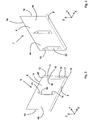
- Figures 1-9 show a first embodiment of a formwork system 1 according to the invention.
- the formwork system 1 shown in figure 1 comprises four sets 2, 3, 4, 5 of plate-shaped formwork elements 6, 7.
- the first set 2 of plate-shaped formwork elements 6 extends parallel to the second set 3 of plate-shaped formwork elements 7.
- the third set 4 of plate-shaped formwork elements 6 extends parallel to the fourth set 5 of plate-shaped formwork elements 7.
- the formwork element 6 comprises a plate-shaped part 8 which is made of a metal or a plastic material.
- the plate-shaped part 8 has, for example, a length in x-direction of 0.75 -1.5 m, preferably 1 m; a height in z-direction of 0.5 - 1 m, preferably 0.65 m, and a thickness in y-direction of 2 - 5 mm, preferably 3 mm.
- the formwork element 6 is provided with a flange 9 which extends transversely to the plate-shaped part 8.
- the formwork element 6 is further provided with a first and a second stiffening rib 10, 11.
- the stiffening ribs 10, 11 extend transversely to the plate-shaped part 8 and in the z-direction.
- the first stiffening rib 10 is located near a first transverse side 12 of the plate-shaped part 8, whilst the second stiffening rib 11 is located near the centre between the first transverse side 12 and a second transverse side 13 of the plate-shaped part 8.
- the stiffening ribs 10, 11 extend in the z-direction between an upper side 14 and a bottom side 15 of the plate-shaped part 8, with bevelled ends 16, 17 located spaced from the upper side 14 and the bottom side 15, respectively.
- the stiffening ribs 10, 11 are further provided with passages 18,19.
- the formwork element 7 is largely similar to the formwork element 6.
- the difference between the formwork element 7 and the formwork element 6 is that in the case of the formwork element 6 the first stiffening rib 20 is located near the second transverse side 13 rather than near the first transverse side 12.
- the second stiffening rib 11 is located near the centre, between the first transverse side 12 and a second transverse side 13 of the plate-shaped part 8.
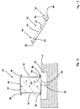
- the formwork system 1 shown in figure 1 further comprises angle-shaped formwork elements 21, 22 which, as is clearly shown in figures 4 and 5 , are provided with plate-shaped parts 8 that extend transversely to each other.
- the formwork element 21, which forms an inside corner is further provided with flanges 9 located in the inside corner of 90 degrees formed by the plate-shaped parts 8.
- the formwork element 22, which forms an outside corner is further provided with flanges 9 located in the outside corner of 270 degrees formed by the plate-shaped parts 8.
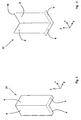
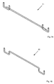
- the formwork system shown in figure 1 further comprises a number of spacers 23 which, as is clearly shown in figure 6 , are provided with a plate-shaped metal strip 24, with U-shaped connecting elements 25 provided at ends of the plate-shaped strip 24.
- Each connecting element 25 comprises a first leg portion 27, which extends downward, transversely to the plate-shaped strip 24, a second leg portion 27, which extends parallel to the first leg portion 26, and a bridge portion 28, which extends between the leg parts 26, 27, parallel to the plate-shaped strip 24.
- a passage 29 is provided near the centre of the plate-shaped strip 24.
- the formwork system 1 shown in figure 1 further comprises a number of U-shaped brackets 30 which, as is clearly shown in figure 7 , are provided with a plate-shaped metal strip 31, with U-shaped holders 32 provided at ends of the plate-shaped strip 31.
- Each U-shaped holder 32 comprises a first leg portion 33, which extends downward, transversely to the plate-shaped strip 31, a second leg portion 34, which extends parallel to the first leg portion 33, and a bridge portion 35, which extends between the leg parts 33, 34, parallel to the plate-shaped strip 31.
- the formwork system 1 shown in figure 1 further comprises wooden slats 36, threaded metal rods 37, metal pins 38 and plastic foam plates 39.
- insulating plastic foam plates 39 are laid on a ground surface 41 comprising a stable portion 40.
- the plastic foam plates 39 have a width that equals the spacing between the first legs 26 of the spacers 23. Then a number of spacers are positioned in spaced relationship over the plastic foam plates 39.
- the spacers 23 are fixed in the ground 41, using metal pins 38.
- the plate-shaped formwork elements 6, 7 are placed in the U-shaped connecting elements 25, with the formwork elements 6 being positioned opposite to the formwork elements 7.
- the formwork elements 6 are positioned so that the part 42 provided with a stiffening rib 10 of a first formwork element 6 abuts with a side remote from the flanged 9 against a part 43 of the second formwork element 6 that is located near the second transverse side 13.
- the parts 42, 43 of the formwork elements 6 overlap.
- the adjoining formwork elements 6, the formwork element 22 adjacent thereto, which forms an outside corner, and the formwork elements 6 adjacent thereto are arranged in successive tile-like overlapping relationship.
- adjoining formwork elements 7, the formwork element 21 adjacent thereto, which forms an inside corner, and the formwork elements 7 adjacent thereto are arranged in successive overlapping tile-like relationship.
- the part 44 provided with a stiffening rib 10 of a first formwork element 7 abuts with a side remote from the flanged 9 against a part 45 of a second formwork element 7 that is located near the first transverse side 12.
- the flanges 8 of the formwork elements 6, 7 rest in the U-shaped connecting elements 25. Due to the provision of the flanges 8, the formwork elements 6, 7 can stand independently without any additional support. To realise the desired dimensions of the formwork system 1, the formwork elements 6 can be moved relative to each other in the longitudinal direction L parallel to the formwork elements 6, wherein the first formwork element 6 can be moved relative to the second formwork element 6 until the first transverse side 12 abuts against the central stiffening rib 11 of the second formwork element 6. The same goes for the formwork elements 7.
- the slats 36 can be provided over the entire length of the plate-shaped parts 8.
- U-shaped brackets 30 are placed over the upper sides 14 of the formwork elements 6, 7, 21, 22, thereby bringing the plate-shaped parts 8 of the formwork elements 6, 7, 21, 22 into abutment with the facing sides of the first legs 33 of the U-shaped holders 32.
- Wooden slats 36 are laid also in said U-shaped holders 32.
- concrete mortar can be poured into the space 46 defined by the formwork elements 6, 7, 21, 22.
- pouring is started on that side of the formwork system 1 where the part 43, 45 is directly pressed against the part 42, 44 upon pouring of the concrete mortar.
- this is near position A wherein subsequently concrete mortar is poured into the space 46 over the entire length of the formwork system 1.
- Forces being exerted on the plate-shaped parts 8 by the concrete mortar will be effectively taken up by the stiffening ribs 10, 11 that extend transversely to the longitudinal direction L and the wooden slats 36 and flanges 9 that extend in the longitudinal direction L, with substantially no deformations of the plate-shaped parts 8.
- the foundation beam 47 thus formed will have the desired shape. If the plate-shaped parts 8 were to deform, this would make it necessary to use additional concrete mortar so as to obtain the same desired height in z-direction. Moreover, deformed plate-shaped parts 8 can no longer be reused.
- the formwork elements 6, 7, 21, 22 are removed after curing of the poured concrete mortar. If desired, the formwork elements 6, 7, 21, 22 can be connected together by means of threaded rods 37 extending through the passages 18, 19, which are connected to the stiffening ribs 10, 11, 20, as a result of which a number of interconnected formwork elements 6, 22; 7, 21 can be jointly moved to another position for forming an identical foundation beam 47.
- FIG 10 shows a second embodiment of a formwork system 51 according to the invention.
- the formwork system 51 is different from the formwork 1 in that it is provided with spacers 52 which, as is clearly shown in figure 11 , are provided with a plate-shaped metal strip 53, with U-shaped connecting elements 54 provided at ends of the plate-shaped strip 53.
- Each connecting element 54 comprises a first leg portion 55, which extends transversely to the plate-shaped strip 53, and a second leg portion 56, which extends parallel to the first leg portion 53.
- a passage 57 is provided near the centre of the plate-shaped strip 53.
- the formwork system 51 is suitable for use on a ground surface 41 where no plastic foam plates 39 are used and the foundation beam 47 lies directly on the ground surface 41.
- stiffening ribs include an angle of, for example, 45 degrees with the longitudinal direction.
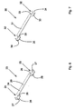
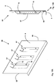
- Figures 12-14 show a third embodiment of a formwork system 61 according to the invention.
- the formwork system 61 is different from the formwork system 1 as regards the configuration of the plate-shaped formwork elements 62 and the U-shaped connecting elements 63.
- the formwork system 61 further functions similarly to the formwork system 1.
- the plate-shaped formwork element 62 is provided with two tubular stiffening ribs 64, which are evenly spaced from the nearby transverse side 65.
- the U-shaped connecting element 63 is made of a wire-shaped material, such as steel wire, for example.
- the U-shaped connecting element 63 is otherwise similar to the U-shaped connecting element 23.
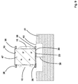
- Figures 15A and 15B show another embodiment of a plate-shaped formwork element 66 which is provided with three tubular stiffening ribs 67, with the middle stiffening rib 67 being located near the centre of the plate-shaped part 8 and the stiffening ribs 67 being present on either side thereof, evenly spaced from the nearby transverse side 68.
- the plate 8 is connected to a side 69 of an angle section 70 at the bottom side, whilst a second side of the angle section 70 forms the flange 9.
- the angle section 70 and the plate 8 may be welded, bolted or glued together or be joined together by other means.
- the plate 8 is made of plastic material, such as plastic-reinforced glass fibre.
- the angle section 70 and the tubular stiffening ribs 67 may be made of plastic material in that case.
- FIG 16 shows another embodiment of a U-shaped connecting element 71 which is made of a wire-shaped material, such as steel wire, for example.
- the U-shaped connecting element 71 is otherwise similar to the U-shaped connecting element 11.
Landscapes
- Engineering & Computer Science (AREA)
- Life Sciences & Earth Sciences (AREA)
- General Life Sciences & Earth Sciences (AREA)
- Mining & Mineral Resources (AREA)
- Paleontology (AREA)
- Civil Engineering (AREA)
- General Engineering & Computer Science (AREA)
- Structural Engineering (AREA)
- Forms Removed On Construction Sites Or Auxiliary Members Thereof (AREA)
Claims (14)
- Schalungssystem (1, 51, 61), das zum Einbringen von Beton geeignet ist, wobei das Schalungssystem (1, 51, 61) plattenförmige Schalungselemente (6, 7, 62, 66) zur Positionierung im Wesentlichen transversal zu einer Bodenoberfläche umfasst, wobei ein erster Satz (2, 3, 4, 5) plattenförmiger Schalungselemente gegenüber einem zweiten Satz (2, 3, 4, 5) plattenförmiger Schalungselemente (6, 7, 62, 66) positioniert ist, im Wesentlichen parallel da-zu und in einer vorbestimmten Distanz davon beabstandet ist, dadurch gekennzeichnet, dass mindestens zwei plattenförmige Schalungselemente (6, 7, 62, 66) mindestens des ersten Satzes (2, 3, 4, 5) jeweils mit Versteifungsrippen (10, 11, 20, 64, 67) zwischen einer unteren Seite (15) des plattenförmigen Schalungselements, die nahe der Bodenoberfläche angeordnet ist, und einer oberen Seite (14) des plattenförmigen Schalungselements, die parallel dazu, um eine gewisse Distanz davon beabstandet verläuft, versehen sind, wobei die Versteifungsrippen (10, 11, 20, 64, 67) an einer von dem zweiten Satz (2, 3, 4, 5) entfernten Seite der plattenförmigen Schalungselemente (6, 7, 62, 66) angeordnet sind, wo-bei die zwei plattenförmigen Schalungselemente (6, 7, 62, 66), die praktisch gegeneinander anliegen, relativ zueinander in einer Längsrichtung (L) parallel zu der Bodenoberfläche beweglich sind.
- Schalungssystem (1, 51, 61) gemäß Anspruch 1, dadurch gekennzeichnet, dass die Versteifungsrippen (10, 11, 20, 64, 67) im Wesentlichen transversal zu der Bodenoberfläche verlaufen.
- Schalungssystem (1, 51, 61) gemäß Anspruch 2, dadurch gekennzeichnet, dass das plattenförmige Schalungselement eine erste und eine zweite transversale Seite (12, 13, 65, 68), die transversal zu der Längsrichtung verlaufen, sowie mindestens zwei Versteifungsrippen (10, 11, 20, 64, 67) umfasst, wobei eine erste der zwei Versteifungsrippen (10, 20, 67) in der Nähe der ersten transversalen Seite angeordnet ist, während eine zweite der zwei Versteifungsrippen (11, 67) in der Nähe der Mitte zwischen der ersten und der zweiten transversalen Seite (12, 13, 68) angeordnet ist.
- Schalungssystem (1, 51, 61) gemäß einem der vorstehenden Ansprüche, dadurch gekennzeichnet, dass die Versteifungsrippen (10, 11, 20, 64, 67) der Schalungselemente (6, 7, 62, 66), die zueinander benachbart angeordnet sind, miteinander verbindbar sind.
- Schalungssystem (1, 51, 61) gemäß einem der vorstehenden Ansprüche, dadurch gekennzeichnet, dass das Schalungssystem (1) mit Abstandhaltern (23, 52) zur Positionierung auf einer Bodenoberfläche versehen ist, wobei die Abstandhalter jeweils mindestens zwei beabstandete Verbindungselemente (25, 54, 63, 71) umfassen, wobei die positionierten gegenüberliegenden Schalungselemente (6, 7, 62, 66) mit den beabstandeten Verbindungselementen (25, 54, 63, 71) verbindbar sind.
- Schalungssystem (1, 51, 61) gemäß Anspruch 5, dadurch gekennzeichnet, dass die plattenförmigen Schalungselemente (6, 7, 62, 66) lösbar mit den Abstandhaltern (23, 52) verbunden sind.
- Schalungssystem (1, 51, 61) gemäß Anspruch 5 oder 6, dadurch gekennzeichnet, dass der Abstandhalter (23, 52) streifenförmig ist, wobei die Verbindungselemente (25, 54, 63, 71) U-förmig sind.
- Schalungssystem (1, 51, 61) gemäß Anspruch 7, dadurch gekennzeichnet, dass das plattenförmige Schalungselement (6, 7, 62, 66) mit einem Flansch (9) versehen ist, der in Längsrichtung (L), parallel zu der Bodenoberfläche, verläuft, wobei der Flansch (9) in dem U-förmigen Verbindungselement (25, 54, 63, 71) des Abstandhalters (23, 52) positioniert sein kann.
- Schalungssystem (1, 51, 61) gemäß Anspruch 7 oder 8, dadurch gekennzeichnet, dass Schalungselemente (6, 7, 62, 66) sowie mindestens eine längliche Leiste (36) lösbar in benachbarten U-förmigen Verbindungselementen (25, 54, 63, 71) der Abstandhalter (23, 52) positioniert sein können, wobei die längliche Leiste (36) an der Seite der Schalungselemente (6, 7) angeordnet ist, die mit den Versteifungsrippen (10, 11, 20, 64, 67) versehen ist.
- Schalungssystem (1, 51, 61) gemäß einem der vorstehenden Ansprüche, dadurch gekennzeichnet, dass das Schalungssystem (1) U-förmige Halterungen (30) zur Positionierung über gegenüberliegenden Schalungselementen (6, 7, 62, 66) an einer von der Bodenober-fläche entfernten Seite umfasst, wobei jede U-förmige Halterung (30) mit U-förmigen Haltern (32) versehen ist, wobei mindestens eine Leiste (36) lösbar in benachbarten U-förmigen Haltern (32) der U-förmigen Halterungen positioniert sein kann.
- Plattenförmiges Schalungselement (6, 7, 62, 66), das in Verwendung in einem Schalungssystem (1, 51, 61) gemäß einem der vorstehenden Ansprüche angebracht ist, wobei das plattenförmige Schalungselement (6, 7, 62, 66) mit Versteifungsrippen (10, 11, 20, 64, 67) versehen ist, die mindestens teilweise transversal zu einer Längsrichtung (L) des platten-förmigen Schalungselements (6, 7, 62, 66) verlaufen.
- Plattenförmiges Schalungselement (6, 7, 62, 66) gemäß Anspruch 11, dadurch gekennzeichnet, dass das plattenförmige Schalungselement (6, 7, 62, 66) mit einem Flansch (9) versehen ist, der parallel zu der Längsrichtung (L), transversal zu einem plattenförmigen Teil (8) des Schalungselements verläuft.
- Verfahren zum Einbringen von Beton, bei dem ein Schalungssystem (1, 51, 61) gemäß einem der vorstehenden Ansprüche 1 - 10 auf einer Bodenoberfläche platziert wird, plattenförmige Schalungselemente (6, 7, 62, 66) relativ zueinander an eine gewünschte relative Position bewegt werden, Betonmörtel in einen Raum (46) eingebracht wird, der durch Schalungselemente (6, 7, 62, 66) des Schalungssystems (1, 51, 61) bestimmt ist, wonach das Schalungssystem (1, 51, 61) mindestens teilweise entfernt wird.
- Verfahren gemäß Anspruch 13, dadurch gekennzeichnet, dass, nachdem die miteinander verbundenen Schalungselemente (6, 7, 62, 66) auf der Bodenoberfläche verwendet wurden, die miteinander verbundenen Schalungselemente (6, 7, 62, 66) an einer anderen Stelle auf der Bodenoberfläche positioniert werden können.
Applications Claiming Priority (1)
| Application Number | Priority Date | Filing Date | Title |
|---|---|---|---|
| NL2010863A NL2010863C2 (nl) | 2013-05-27 | 2013-05-27 | Bekistingssysteem, plaatvormig bekistingselement geschikt voor een dergelijk bekistingssysteem alsmede werkwijze voor het storten van beton. |
Publications (2)
| Publication Number | Publication Date |
|---|---|
| EP2808451A1 EP2808451A1 (de) | 2014-12-03 |
| EP2808451B1 true EP2808451B1 (de) | 2016-05-11 |
Family
ID=48703787
Family Applications (1)
| Application Number | Title | Priority Date | Filing Date |
|---|---|---|---|
| EP14169411.7A Not-in-force EP2808451B1 (de) | 2013-05-27 | 2014-05-22 | Gründung |
Country Status (2)
| Country | Link |
|---|---|
| EP (1) | EP2808451B1 (de) |
| NL (1) | NL2010863C2 (de) |
Families Citing this family (1)
| Publication number | Priority date | Publication date | Assignee | Title |
|---|---|---|---|---|
| AU2015204404B1 (en) * | 2015-07-14 | 2016-08-11 | Pantano Investments Pty Ltd | Creation of Surface-mounted Sills or Hobs on Cast-in-situ Concrete Building Slabs |
Family Cites Families (1)
| Publication number | Priority date | Publication date | Assignee | Title |
|---|---|---|---|---|
| NL1022075C2 (nl) * | 2002-12-04 | 2004-06-07 | Bouwbedrijf Van Der Heijden B | Bekistingssysteem voor het storten van een fundering. |
-
2013
- 2013-05-27 NL NL2010863A patent/NL2010863C2/nl not_active IP Right Cessation
-
2014
- 2014-05-22 EP EP14169411.7A patent/EP2808451B1/de not_active Not-in-force
Also Published As
| Publication number | Publication date |
|---|---|
| NL2010863C2 (nl) | 2014-12-01 |
| EP2808451A1 (de) | 2014-12-03 |
Similar Documents
| Publication | Publication Date | Title |
|---|---|---|
| US20100269439A1 (en) | Insulated panel and system for construction of a modular building and method of fabrication thereof | |
| US10273698B2 (en) | Connector for form boards and system for cast construction | |
| KR102128100B1 (ko) | 가변식 탈형 보 데크 | |
| US9045894B2 (en) | Center-supported wall panel | |
| KR100949785B1 (ko) | 피씨 보 제작용 몰드 | |
| EP2808451B1 (de) | Gründung | |
| RU2633435C2 (ru) | Система удержания для элемента оборудования на бетонной плите | |
| KR101954387B1 (ko) | 격자형 프리캐스트 콘크리트 구조물과 그 시공방법 | |
| KR100891347B1 (ko) | 슬래브 거푸집의 지지구조 | |
| KR101759710B1 (ko) | 건축물의 보 성형을 위한 보 거푸집 받침방법 | |
| EP1936038A1 (de) | Verlorene Schalung | |
| WO2016203483A1 (en) | Composite framing and wall | |
| WO2015196264A1 (en) | Connection set for formwork beams | |
| KR102128099B1 (ko) | 가변식 탈형 보 데크 시스템 | |
| KR102818316B1 (ko) | 보 거푸집 지지장치 | |
| KR101880813B1 (ko) | 샌드위치 피씨 패널 구조물 및 이를 이용한 구조물 시공방법 | |
| KR101043751B1 (ko) | 슬라브용 단열 데크플레이트 | |
| JP6761264B2 (ja) | 水平部材の施工管理方法 | |
| RU108472U1 (ru) | Опалубка поддерживающая для сборного железобетонного перекрытия кесонного типа | |
| JP2022037522A (ja) | 梁の施工方法、及び梁型枠支持構造 | |
| US1865500A (en) | Wall construction | |
| CN223017918U (zh) | 一种构造柱免模施工预制结构 | |
| RU2697354C2 (ru) | Опалубка для бетона и поддерживающая стойка для опалубки | |
| KR101469085B1 (ko) | 슬래브 시공용 이동식 가설 시스템 | |
| JP2019094671A (ja) | コンクリート型枠門型形状組立て、金具。 |
Legal Events
| Date | Code | Title | Description |
|---|---|---|---|
| PUAI | Public reference made under article 153(3) epc to a published international application that has entered the european phase |
Free format text: ORIGINAL CODE: 0009012 |
|
| 17P | Request for examination filed |
Effective date: 20140522 |
|
| AK | Designated contracting states |
Kind code of ref document: A1 Designated state(s): AL AT BE BG CH CY CZ DE DK EE ES FI FR GB GR HR HU IE IS IT LI LT LU LV MC MK MT NL NO PL PT RO RS SE SI SK SM TR |
|
| AX | Request for extension of the european patent |
Extension state: BA ME |
|
| R17P | Request for examination filed (corrected) |
Effective date: 20150520 |
|
| RBV | Designated contracting states (corrected) |
Designated state(s): AL AT BE BG CH CY CZ DE DK EE ES FI FR GB GR HR HU IE IS IT LI LT LU LV MC MK MT NL NO PL PT RO RS SE SI SK SM TR |
|
| GRAP | Despatch of communication of intention to grant a patent |
Free format text: ORIGINAL CODE: EPIDOSNIGR1 |
|
| INTG | Intention to grant announced |
Effective date: 20151204 |
|
| GRAS | Grant fee paid |
Free format text: ORIGINAL CODE: EPIDOSNIGR3 |
|
| GRAA | (expected) grant |
Free format text: ORIGINAL CODE: 0009210 |
|
| AK | Designated contracting states |
Kind code of ref document: B1 Designated state(s): AL AT BE BG CH CY CZ DE DK EE ES FI FR GB GR HR HU IE IS IT LI LT LU LV MC MK MT NL NO PL PT RO RS SE SI SK SM TR |
|
| REG | Reference to a national code |
Ref country code: GB Ref legal event code: FG4D |
|
| REG | Reference to a national code |
Ref country code: CH Ref legal event code: EP |
|
| REG | Reference to a national code |
Ref country code: AT Ref legal event code: REF Ref document number: 798793 Country of ref document: AT Kind code of ref document: T Effective date: 20160515 |
|
| REG | Reference to a national code |
Ref country code: IE Ref legal event code: FG4D |
|
| REG | Reference to a national code |
Ref country code: DE Ref legal event code: R096 Ref document number: 602014001847 Country of ref document: DE |
|
| REG | Reference to a national code |
Ref country code: LT Ref legal event code: MG4D |
|
| REG | Reference to a national code |
Ref country code: NL Ref legal event code: MP Effective date: 20160511 |
|
| PG25 | Lapsed in a contracting state [announced via postgrant information from national office to epo] |
Ref country code: NO Free format text: LAPSE BECAUSE OF FAILURE TO SUBMIT A TRANSLATION OF THE DESCRIPTION OR TO PAY THE FEE WITHIN THE PRESCRIBED TIME-LIMIT Effective date: 20160811 Ref country code: FI Free format text: LAPSE BECAUSE OF FAILURE TO SUBMIT A TRANSLATION OF THE DESCRIPTION OR TO PAY THE FEE WITHIN THE PRESCRIBED TIME-LIMIT Effective date: 20160511 Ref country code: LT Free format text: LAPSE BECAUSE OF FAILURE TO SUBMIT A TRANSLATION OF THE DESCRIPTION OR TO PAY THE FEE WITHIN THE PRESCRIBED TIME-LIMIT Effective date: 20160511 Ref country code: NL Free format text: LAPSE BECAUSE OF FAILURE TO SUBMIT A TRANSLATION OF THE DESCRIPTION OR TO PAY THE FEE WITHIN THE PRESCRIBED TIME-LIMIT Effective date: 20160511 |
|
| REG | Reference to a national code |
Ref country code: AT Ref legal event code: MK05 Ref document number: 798793 Country of ref document: AT Kind code of ref document: T Effective date: 20160511 |
|
| PG25 | Lapsed in a contracting state [announced via postgrant information from national office to epo] |
Ref country code: LV Free format text: LAPSE BECAUSE OF FAILURE TO SUBMIT A TRANSLATION OF THE DESCRIPTION OR TO PAY THE FEE WITHIN THE PRESCRIBED TIME-LIMIT Effective date: 20160511 Ref country code: PT Free format text: LAPSE BECAUSE OF FAILURE TO SUBMIT A TRANSLATION OF THE DESCRIPTION OR TO PAY THE FEE WITHIN THE PRESCRIBED TIME-LIMIT Effective date: 20160912 Ref country code: RS Free format text: LAPSE BECAUSE OF FAILURE TO SUBMIT A TRANSLATION OF THE DESCRIPTION OR TO PAY THE FEE WITHIN THE PRESCRIBED TIME-LIMIT Effective date: 20160511 Ref country code: HR Free format text: LAPSE BECAUSE OF FAILURE TO SUBMIT A TRANSLATION OF THE DESCRIPTION OR TO PAY THE FEE WITHIN THE PRESCRIBED TIME-LIMIT Effective date: 20160511 Ref country code: GR Free format text: LAPSE BECAUSE OF FAILURE TO SUBMIT A TRANSLATION OF THE DESCRIPTION OR TO PAY THE FEE WITHIN THE PRESCRIBED TIME-LIMIT Effective date: 20160812 Ref country code: SE Free format text: LAPSE BECAUSE OF FAILURE TO SUBMIT A TRANSLATION OF THE DESCRIPTION OR TO PAY THE FEE WITHIN THE PRESCRIBED TIME-LIMIT Effective date: 20160511 Ref country code: ES Free format text: LAPSE BECAUSE OF FAILURE TO SUBMIT A TRANSLATION OF THE DESCRIPTION OR TO PAY THE FEE WITHIN THE PRESCRIBED TIME-LIMIT Effective date: 20160511 |
|
| PG25 | Lapsed in a contracting state [announced via postgrant information from national office to epo] |
Ref country code: IT Free format text: LAPSE BECAUSE OF FAILURE TO SUBMIT A TRANSLATION OF THE DESCRIPTION OR TO PAY THE FEE WITHIN THE PRESCRIBED TIME-LIMIT Effective date: 20160511 |
|
| PG25 | Lapsed in a contracting state [announced via postgrant information from national office to epo] |
Ref country code: EE Free format text: LAPSE BECAUSE OF FAILURE TO SUBMIT A TRANSLATION OF THE DESCRIPTION OR TO PAY THE FEE WITHIN THE PRESCRIBED TIME-LIMIT Effective date: 20160511 Ref country code: SK Free format text: LAPSE BECAUSE OF FAILURE TO SUBMIT A TRANSLATION OF THE DESCRIPTION OR TO PAY THE FEE WITHIN THE PRESCRIBED TIME-LIMIT Effective date: 20160511 Ref country code: CZ Free format text: LAPSE BECAUSE OF FAILURE TO SUBMIT A TRANSLATION OF THE DESCRIPTION OR TO PAY THE FEE WITHIN THE PRESCRIBED TIME-LIMIT Effective date: 20160511 Ref country code: RO Free format text: LAPSE BECAUSE OF FAILURE TO SUBMIT A TRANSLATION OF THE DESCRIPTION OR TO PAY THE FEE WITHIN THE PRESCRIBED TIME-LIMIT Effective date: 20160511 Ref country code: DK Free format text: LAPSE BECAUSE OF FAILURE TO SUBMIT A TRANSLATION OF THE DESCRIPTION OR TO PAY THE FEE WITHIN THE PRESCRIBED TIME-LIMIT Effective date: 20160511 |
|
| REG | Reference to a national code |
Ref country code: DE Ref legal event code: R097 Ref document number: 602014001847 Country of ref document: DE |
|
| REG | Reference to a national code |
Ref country code: IE Ref legal event code: MM4A |
|
| PG25 | Lapsed in a contracting state [announced via postgrant information from national office to epo] |
Ref country code: PL Free format text: LAPSE BECAUSE OF FAILURE TO SUBMIT A TRANSLATION OF THE DESCRIPTION OR TO PAY THE FEE WITHIN THE PRESCRIBED TIME-LIMIT Effective date: 20160511 Ref country code: SM Free format text: LAPSE BECAUSE OF FAILURE TO SUBMIT A TRANSLATION OF THE DESCRIPTION OR TO PAY THE FEE WITHIN THE PRESCRIBED TIME-LIMIT Effective date: 20160511 Ref country code: AT Free format text: LAPSE BECAUSE OF FAILURE TO SUBMIT A TRANSLATION OF THE DESCRIPTION OR TO PAY THE FEE WITHIN THE PRESCRIBED TIME-LIMIT Effective date: 20160511 |
|
| PLBE | No opposition filed within time limit |
Free format text: ORIGINAL CODE: 0009261 |
|
| STAA | Information on the status of an ep patent application or granted ep patent |
Free format text: STATUS: NO OPPOSITION FILED WITHIN TIME LIMIT |
|
| PG25 | Lapsed in a contracting state [announced via postgrant information from national office to epo] |
Ref country code: MC Free format text: LAPSE BECAUSE OF FAILURE TO SUBMIT A TRANSLATION OF THE DESCRIPTION OR TO PAY THE FEE WITHIN THE PRESCRIBED TIME-LIMIT Effective date: 20160511 |
|
| REG | Reference to a national code |
Ref country code: FR Ref legal event code: ST Effective date: 20170301 |
|
| 26N | No opposition filed |
Effective date: 20170214 |
|
| PG25 | Lapsed in a contracting state [announced via postgrant information from national office to epo] |
Ref country code: FR Free format text: LAPSE BECAUSE OF NON-PAYMENT OF DUE FEES Effective date: 20160711 |
|
| PG25 | Lapsed in a contracting state [announced via postgrant information from national office to epo] |
Ref country code: IE Free format text: LAPSE BECAUSE OF NON-PAYMENT OF DUE FEES Effective date: 20160522 Ref country code: SI Free format text: LAPSE BECAUSE OF FAILURE TO SUBMIT A TRANSLATION OF THE DESCRIPTION OR TO PAY THE FEE WITHIN THE PRESCRIBED TIME-LIMIT Effective date: 20160511 |
|
| REG | Reference to a national code |
Ref country code: CH Ref legal event code: PL |
|
| PG25 | Lapsed in a contracting state [announced via postgrant information from national office to epo] |
Ref country code: CH Free format text: LAPSE BECAUSE OF NON-PAYMENT OF DUE FEES Effective date: 20170531 Ref country code: LI Free format text: LAPSE BECAUSE OF NON-PAYMENT OF DUE FEES Effective date: 20170531 |
|
| PG25 | Lapsed in a contracting state [announced via postgrant information from national office to epo] |
Ref country code: HU Free format text: LAPSE BECAUSE OF FAILURE TO SUBMIT A TRANSLATION OF THE DESCRIPTION OR TO PAY THE FEE WITHIN THE PRESCRIBED TIME-LIMIT; INVALID AB INITIO Effective date: 20140522 |
|
| PG25 | Lapsed in a contracting state [announced via postgrant information from national office to epo] |
Ref country code: MT Free format text: LAPSE BECAUSE OF NON-PAYMENT OF DUE FEES Effective date: 20160531 Ref country code: MK Free format text: LAPSE BECAUSE OF FAILURE TO SUBMIT A TRANSLATION OF THE DESCRIPTION OR TO PAY THE FEE WITHIN THE PRESCRIBED TIME-LIMIT Effective date: 20160511 Ref country code: IS Free format text: LAPSE BECAUSE OF FAILURE TO SUBMIT A TRANSLATION OF THE DESCRIPTION OR TO PAY THE FEE WITHIN THE PRESCRIBED TIME-LIMIT Effective date: 20160511 Ref country code: LU Free format text: LAPSE BECAUSE OF NON-PAYMENT OF DUE FEES Effective date: 20160522 Ref country code: CY Free format text: LAPSE BECAUSE OF FAILURE TO SUBMIT A TRANSLATION OF THE DESCRIPTION OR TO PAY THE FEE WITHIN THE PRESCRIBED TIME-LIMIT Effective date: 20160511 |
|
| PG25 | Lapsed in a contracting state [announced via postgrant information from national office to epo] |
Ref country code: BG Free format text: LAPSE BECAUSE OF FAILURE TO SUBMIT A TRANSLATION OF THE DESCRIPTION OR TO PAY THE FEE WITHIN THE PRESCRIBED TIME-LIMIT Effective date: 20160511 |
|
| PG25 | Lapsed in a contracting state [announced via postgrant information from national office to epo] |
Ref country code: AL Free format text: LAPSE BECAUSE OF FAILURE TO SUBMIT A TRANSLATION OF THE DESCRIPTION OR TO PAY THE FEE WITHIN THE PRESCRIBED TIME-LIMIT Effective date: 20160511 Ref country code: TR Free format text: LAPSE BECAUSE OF FAILURE TO SUBMIT A TRANSLATION OF THE DESCRIPTION OR TO PAY THE FEE WITHIN THE PRESCRIBED TIME-LIMIT Effective date: 20160511 |
|
| GBPC | Gb: european patent ceased through non-payment of renewal fee |
Effective date: 20180522 |
|
| PG25 | Lapsed in a contracting state [announced via postgrant information from national office to epo] |
Ref country code: GB Free format text: LAPSE BECAUSE OF NON-PAYMENT OF DUE FEES Effective date: 20180522 |
|
| PGFP | Annual fee paid to national office [announced via postgrant information from national office to epo] |
Ref country code: DE Payment date: 20190529 Year of fee payment: 6 |
|
| PGFP | Annual fee paid to national office [announced via postgrant information from national office to epo] |
Ref country code: BE Payment date: 20190529 Year of fee payment: 6 |
|
| REG | Reference to a national code |
Ref country code: DE Ref legal event code: R119 Ref document number: 602014001847 Country of ref document: DE |
|
| REG | Reference to a national code |
Ref country code: BE Ref legal event code: MM Effective date: 20200531 |
|
| PG25 | Lapsed in a contracting state [announced via postgrant information from national office to epo] |
Ref country code: DE Free format text: LAPSE BECAUSE OF NON-PAYMENT OF DUE FEES Effective date: 20201201 Ref country code: BE Free format text: LAPSE BECAUSE OF NON-PAYMENT OF DUE FEES Effective date: 20200531 |