EP2808257A1 - Motor cooling blower and containment structure - Google Patents
Motor cooling blower and containment structure Download PDFInfo
- Publication number
- EP2808257A1 EP2808257A1 EP14169145.1A EP14169145A EP2808257A1 EP 2808257 A1 EP2808257 A1 EP 2808257A1 EP 14169145 A EP14169145 A EP 14169145A EP 2808257 A1 EP2808257 A1 EP 2808257A1
- Authority
- EP
- European Patent Office
- Prior art keywords
- blower
- cooling
- cooling flow
- ecs
- flow
- Prior art date
- Legal status (The legal status is an assumption and is not a legal conclusion. Google has not performed a legal analysis and makes no representation as to the accuracy of the status listed.)
- Granted
Links
Images


Classifications
-
- B—PERFORMING OPERATIONS; TRANSPORTING
- B64—AIRCRAFT; AVIATION; COSMONAUTICS
- B64D—EQUIPMENT FOR FITTING IN OR TO AIRCRAFT; FLIGHT SUITS; PARACHUTES; ARRANGEMENT OR MOUNTING OF POWER PLANTS OR PROPULSION TRANSMISSIONS IN AIRCRAFT
- B64D13/00—Arrangements or adaptations of air-treatment apparatus for aircraft crew or passengers, or freight space
-
- B—PERFORMING OPERATIONS; TRANSPORTING
- B64—AIRCRAFT; AVIATION; COSMONAUTICS
- B64D—EQUIPMENT FOR FITTING IN OR TO AIRCRAFT; FLIGHT SUITS; PARACHUTES; ARRANGEMENT OR MOUNTING OF POWER PLANTS OR PROPULSION TRANSMISSIONS IN AIRCRAFT
- B64D13/00—Arrangements or adaptations of air-treatment apparatus for aircraft crew or passengers, or freight space
- B64D13/06—Arrangements or adaptations of air-treatment apparatus for aircraft crew or passengers, or freight space the air being conditioned
-
- F—MECHANICAL ENGINEERING; LIGHTING; HEATING; WEAPONS; BLASTING
- F04—POSITIVE - DISPLACEMENT MACHINES FOR LIQUIDS; PUMPS FOR LIQUIDS OR ELASTIC FLUIDS
- F04D—NON-POSITIVE-DISPLACEMENT PUMPS
- F04D25/00—Pumping installations or systems
- F04D25/02—Units comprising pumps and their driving means
- F04D25/06—Units comprising pumps and their driving means the pump being electrically driven
-
- F—MECHANICAL ENGINEERING; LIGHTING; HEATING; WEAPONS; BLASTING
- F04—POSITIVE - DISPLACEMENT MACHINES FOR LIQUIDS; PUMPS FOR LIQUIDS OR ELASTIC FLUIDS
- F04D—NON-POSITIVE-DISPLACEMENT PUMPS
- F04D29/00—Details, component parts, or accessories
- F04D29/58—Cooling; Heating; Diminishing heat transfer
- F04D29/5806—Cooling the drive system
-
- F—MECHANICAL ENGINEERING; LIGHTING; HEATING; WEAPONS; BLASTING
- F25—REFRIGERATION OR COOLING; COMBINED HEATING AND REFRIGERATION SYSTEMS; HEAT PUMP SYSTEMS; MANUFACTURE OR STORAGE OF ICE; LIQUEFACTION SOLIDIFICATION OF GASES
- F25B—REFRIGERATION MACHINES, PLANTS OR SYSTEMS; COMBINED HEATING AND REFRIGERATION SYSTEMS; HEAT PUMP SYSTEMS
- F25B9/00—Compression machines, plants or systems, in which the refrigerant is air or other gas of low boiling point
- F25B9/002—Compression machines, plants or systems, in which the refrigerant is air or other gas of low boiling point characterised by the refrigerant
- F25B9/004—Compression machines, plants or systems, in which the refrigerant is air or other gas of low boiling point characterised by the refrigerant the refrigerant being air
-
- B—PERFORMING OPERATIONS; TRANSPORTING
- B64—AIRCRAFT; AVIATION; COSMONAUTICS
- B64D—EQUIPMENT FOR FITTING IN OR TO AIRCRAFT; FLIGHT SUITS; PARACHUTES; ARRANGEMENT OR MOUNTING OF POWER PLANTS OR PROPULSION TRANSMISSIONS IN AIRCRAFT
- B64D13/00—Arrangements or adaptations of air-treatment apparatus for aircraft crew or passengers, or freight space
- B64D13/06—Arrangements or adaptations of air-treatment apparatus for aircraft crew or passengers, or freight space the air being conditioned
- B64D2013/0603—Environmental Control Systems
- B64D2013/0644—Environmental Control Systems including electric motors or generators
-
- Y—GENERAL TAGGING OF NEW TECHNOLOGICAL DEVELOPMENTS; GENERAL TAGGING OF CROSS-SECTIONAL TECHNOLOGIES SPANNING OVER SEVERAL SECTIONS OF THE IPC; TECHNICAL SUBJECTS COVERED BY FORMER USPC CROSS-REFERENCE ART COLLECTIONS [XRACs] AND DIGESTS
- Y02—TECHNOLOGIES OR APPLICATIONS FOR MITIGATION OR ADAPTATION AGAINST CLIMATE CHANGE
- Y02T—CLIMATE CHANGE MITIGATION TECHNOLOGIES RELATED TO TRANSPORTATION
- Y02T50/00—Aeronautics or air transport
- Y02T50/50—On board measures aiming to increase energy efficiency
Definitions
- the subject matter disclosed herein relates to aircraft environmental control and aircraft containment. More specifically, the subject disclosure relates to the cooling of a cabin air compressor motor for an aircraft environmental control system, as well as a containment structure for a compressor rotor of the aircraft.
- Environmental control systems are utilized on various types of aircraft for several purposes, such as in cooling systems for the aircraft.
- components of the ECS may be utilized to remove heat from various aircraft lubrication and electrical systems and/or used to condition aircraft cabin air.
- the cabin air conditioner includes one or more cabin air compressors (CACs) which compress air entering the system. The compressed air is delivered to an environmental control system to bring it to a desired temperature then delivered to the aircraft cabin. After passing through the cabin, the air is typically exhausted to the outside. The air is at least partially recycled.
- the CACs are typically driven by air-cooled electric motors, which are cooled by a flow of cooling air typically drawn by a ram air system.
- Ram air systems typically pull ambient air in through a ram air inlet
- Aircraft compressors commonly include some form of containment structure for the rotors of the aircraft compressor. It is possible for rotors to fragment or break during operation. Thus, containment structures are provided to contain released blade fragments and/or broken rotor segments and prevent them from escaping the aircraft compressor. The effectiveness of the containment structure is generally improved with closer proximity of the containment structure to the rotor.
- the disclosed embodiments include an ECS comprising: a cooling gas inlet and a cooling gas exit connected by pathways wherein a pressure differential between said cooling gas inlet and said cooling gas exit draws cooling flow through said pathways; a movable blower disposed in at least one of the pathways that boosts a flow rate of said cooling flow; and a static structure; wherein said blower directs boosted cooling flow along a surface of said static structure toward said cooling gas exit.
- the ECS may further comprise a cabin air compressor rotor.
- the disclosed embodiments further include an ECS comprising: means for transporting cooling gas between a cooling gas inlet and a cooling gas exit; means for creating a pressure differential between said cooling gas inlet and said cooling gas exit that draws cooling flow through said means for transporting; means for boosting a flow rate of said cooling flow; and means for guiding said boosted cooling flow toward said cooling gas exit; wherein said means for boosting directs boosted cooling flow along a static surface of said means for guiding.
- the disclosed embodiments further include a method of cooling a cabin air compressor assembly comprising: transporting cooling gas between a cooling gas inlet and a cooling gas exit; creating a pressure differential between said cooling gas inlet and said cooling gas exit that draws cooling flow through the assembly; boosting a flow rate of said cooling flow; and guiding said boosted cooling flow toward said cooling gas exit; wherein said boosting step also directs boosted cooling flow along a static surface.
- FIG. 1 is a schematic diagram of the pertinent portions of an environmental control system (ECS) 10 for an aircraft.
- ECS 10 includes one or more cabin air compressors (CACs) 12, which in some embodiments are centrifugal compressors.
- a gas flow 14, which is preferably air, is generated from outside the aircraft or from another source.
- the flow 14 moves through an inlet 13 and enters the CAC 12 at a compressor inlet 16.
- the CAC 12 compresses the flow 14 and urges the flow 14 from the compressor inlet 16 through various pathways that transport the flow 14 to a heat exchanger inlet 20, a ram system 22, an evaporator 24 and an aircraft cabin 26.
- the ram system 22 includes a ram fan inlet 21 that draws air into the ram system 22.
- Each CAC 12 is driven by a CAC motor 28 operably connected to the CAC 12 via a CAC shaft 30.
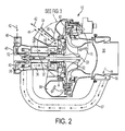
- FIGS. 2 and 3 are cross sectional views that illustrate more details of a CAC 12 embodying the present disclosure.
- FIG. 3 is an expanded view of the area identified by the dotted line in FIG. 2 . Note that the following discussion refers to elements illustrated in both FIG. 2 and FIG. 3 , and that certain elements within the dotted line of FIG. 2 are best illustrated in the expanded view shown in FIG. 3 . For ease of illustration, the reference numbers for certain elements within the dotted line of FIG. 2 are only shown in FIG. 3 .
- the compressor inlet 16 delivers gas 15 to be compressed to a CAC rotor 62.
- a main compressor exit 82 is positioned downstream of the CAC rotor 62.
- a main compressor diffuser 86 (best shown in FIG.
- the CAC motor 28 is an electric motor in one embodiment and has a rotor 32 rotatably located at a CAC tie rod 33.
- the CAC motor 28, when implemented as an electric motor, also includes a stator 36 having a plurality of stator windings 38 disposed radially outboard of the rotor 32.
- the CAC motor 28 also includes one or more bearings 40 disposed at a CAC shaft 30 coupled through a compressor tie rod support 31 to a CAC tie rod 33.
- a cooling flow is drawn across the CAC motor 28.
- the cooling flow is driven generally by a pressure drop from the compressor inlet 16 to the ram system 22, for example, ram fan inlet 21 (as shown in FIG. 1 ).
- the cooling flow includes a motor gap cooling flow 42 and a motor cooling flow 44.
- the motor gap cooling flow 42 is supplied via motor gap cooling inlet 46 at a first end 48 of the CAC motor 28 opposite a second end 50 at which the CAC 12 is disposed.
- the motor gap cooling flow 42 proceeds across thrust bearings 52 located at the first end 48, and across shaft bearings 54 located, for example, at the CAC shaft 30 at the first end 48 and/or the second end 50, thereby removing thermal energy from the thrust bearings 52 and the shaft bearings 54.
- the motor gap cooling flow 42 exits the CAC motor 28 and moves primarily into a blower gas path 60 (best shown in FIG. 3 ).
- the blower gas path 60 includes an inlet path section upstream of a plurality of blower blades 70, along with an exit path section immediately downstream of the plurality of blower blades 70.
- the CAC motor 28 includes a motor shroud 58 which directs the motor gap cooling flow 42 primarily toward the blower gas path 60. A small portion of the motor gap cooling flow 42 directed by the motor shroud 58 may divert through a bleed opening 59 directly to a motor cooling exit 64.
- the disclosed embodiments include a static structure that performs multiple functions, including for example, interference and/or isolation functionality, guide functionality and containment functionality. More specifically, the disclosed static structure guides cooling gas flow 42, 44, interferes with cooling gas flow 42, 44 impacting the compressor rotor 62, and provides some isolation of the cooling gas flow 42, 44 from the compressor rotor 62.
- the static structure further provides containment functionality by forming a part of a containment structure that forms a containment area 100 of the compressor rotor 62.
- the static structure may be implemented as a static seal plate 96 (best shown in FIG. 3 ) having a first seal plate surface 97 and a second seal plate surface 98.
- collector 90 extends from the compressor housing 80 and includes a first collector section 91 and a second collector section 92.
- the blower gas path 60 is formed by the first collector section 91, the blower 68 and the first surface 97 of the static seal plate 96.
- the motor gap cooling flow 42 proceeds substantially radially outwardly toward a collector gas path 61.
- the collector gas path 61 is formed by the second section 92 of the collector 90.
- the collector gas path 61 collects motor gap cooling flow 42 and directs it toward the motor cooling exit 64, which further feeds to, for example, the ram fan inlet 21 (shown in FIG. 1 ).
- the motor cooling flow 44 is drawn from the compressor inlet 16, enters at a motor inlet 66 and proceeds toward the first end 48 via a cooling conduit 67.
- the motor cooling flow 44 proceeds through the CAC motor 28, substantially from the first end 48 to the second end 50 removing thermal energy from the stator windings 38 and other components of the CAC motor 28.
- the motor cooling flow 44 then proceeds on substantially the same path as the motor gap cooling flow 42, passing through the blower gas path 60, the collector gas path 61 and the motor cooling exit 64 toward, for example, the ram fan inlet 21 (shown in FIG. 1 ).
- the blower 68 includes a plurality of blower blades 70 that extend into the blower gas path 60.
- the blower 68 is coupled to the compressor shaft 30 such that when the motor 28 operates to rotate the CAC rotor 62, the motor 28 also rotates the blower 60 and the blower blades 70.
- the rotating blower blades 70 urge the motor gap cooling flow 42 and the motor cooling flow 44 through the blower gas path 60.
- Inclusion of the blower 68 in the CAC 12 increases the pressure differential between the compressor inlet 16 and the ram fan inlet 21 (shown in FIG. 1 ) and increases a mass flow of the motor gap cooling flow 42 and the motor cooling flow 44 across the CAC motor 28.
- the increased pressure differential and increased mass flow increase the cooling of the CAC motor 28 thus increasing performance of the CAC 12 and the ECS 10.
- An example of providing a blower integral with the compressor rotor is shown in U.S. Patent Application No. 2012-0011878-A1 .
- An example of providing a blower separate from the compressor rotor is described and illustrated in the present disclosure.
- the blower 68 may be either separate from or integral with the compressor rotor 62. Because cooling flow is low temperature, where the blower 68 is a separate element from the compressor rotor 62, the blower 68 may be made from lightweight materials such as aluminum, plastic or composite.
- the first seal plate surface 97 forms a portion of the exit path section of the blower gas path 60 and essentially isolates cooling flow 42, 44 from the rotating compressor rotor 62. Because the seal plate 96 is static and does not move, as the cooling flow 42 44 moves downstream of the blower 68 the cooling flow 42, 44 is not subject to additional swirl from the rotating compressor rotor 62.
- the blower 68 and the static seal plate 96 also form a containment structure that defines a containment area 100 (best shown in FIG. 3 ) for the compressor rotor 62.
- Aircraft compressors commonly include some form of containment structure for the rotors of the aircraft compressor. It is possible for rotors to fragment or break.
- the containment structure 68, 96 functions to contain released blade fragments and prevent them from escaping the aircraft compressor.
- the effectiveness of the containment structure 68, 96 may be generally improved because mounting the blower 68 to the compressor shaft 30 as shown allows the static seal plate 96 to be placed in relatively close proximity to the compressor rotor 62.
- the blower 68 and the static seal plate 96 fulfill multiple roles.
- the blower's 68 roles and features include but are not limited to (i) forming part of the blower gas path 60 for passing cooling flow 42, 44, (ii) boosting cooling flow 42, 44, (iii) forming part of the containment structure 68, 96 for the compressor rotor 62, (iv) coupling the blower 68 to the compressor shaft 30 to allow the static seal plate 96 to be place in relatively close proximity to the compressor rotor 62, thereby keeping the containment area 100 relatively small, which is optimum, and (v) where the blower 68 is not integral with the compressor rotor 62, allowing the blower 68 to be made from lightweight materials such as aluminum, plastic or composite.
- the static seal plate's 96 roles and features include but are not limited to (i) forming part of the exit path section of the blower gas path 60, (ii) interfering with and/or providing some isolation of cooling flow 42, 44 to limit the cooling flow 42, 44 from impacting the compressor rotor 62 to thereby reduce the potential for the rotating compressor to add swirl to the cooling flow 42 44, (iii) guiding the cooling flow 42, 44 into the collector gas path 61 and toward the motor cooling exit 64, (iv) forming part of the containment structure 68, 96 for the compressor rotor 62, and (v) in combination with the location of the blower 68 on the compressor shaft 30, allowing the static seal plate 96 to be placed in relatively close proximity to the compressor rotor 62, thereby keeping the containment area 100 relatively small, which is optimum.
- both the blower 68 and the static seal plate 96 can be constructed from lightweight material that does not add significant weight to the aircraft compressor. Also, adding the blower 68 increases the axial length of the compressor/blower rotor by less than 5%.
Landscapes
- Engineering & Computer Science (AREA)
- Health & Medical Sciences (AREA)
- General Health & Medical Sciences (AREA)
- Pulmonology (AREA)
- Aviation & Aerospace Engineering (AREA)
- Mechanical Engineering (AREA)
- General Engineering & Computer Science (AREA)
- Physics & Mathematics (AREA)
- Thermal Sciences (AREA)
- Structures Of Non-Positive Displacement Pumps (AREA)
Abstract
Description
- The subject matter disclosed herein relates to aircraft environmental control and aircraft containment. More specifically, the subject disclosure relates to the cooling of a cabin air compressor motor for an aircraft environmental control system, as well as a containment structure for a compressor rotor of the aircraft.
- Environmental control systems (ECS) are utilized on various types of aircraft for several purposes, such as in cooling systems for the aircraft. For example, components of the ECS may be utilized to remove heat from various aircraft lubrication and electrical systems and/or used to condition aircraft cabin air. The cabin air conditioner includes one or more cabin air compressors (CACs) which compress air entering the system. The compressed air is delivered to an environmental control system to bring it to a desired temperature then delivered to the aircraft cabin. After passing through the cabin, the air is typically exhausted to the outside. The air is at least partially recycled. The CACs are typically driven by air-cooled electric motors, which are cooled by a flow of cooling air typically drawn by a ram air system. Ram air systems typically pull ambient air in through a ram air inlet
- The flow of CAC motor cooling air and thus the performance of the electric motor and CAC are typically limited by the pressure drop from the CAC inlet to the ram air system. Such a limitation may result in reduced performance of the CAC. Thus, it would be advantageous to enhance the flow of cooling air. These and other issues are addressed by published
U.S. Patent Application No. 2012-0011878-A1 that discloses the provision of a blower in an exit channel of the aircraft engine. The blower increases a pressure differential and a mass flow, thereby increasing the flow of cooling air, thereby increasing the performance of the CAC and the ECS. - Aircraft compressors commonly include some form of containment structure for the rotors of the aircraft compressor. It is possible for rotors to fragment or break during operation. Thus, containment structures are provided to contain released blade fragments and/or broken rotor segments and prevent them from escaping the aircraft compressor. The effectiveness of the containment structure is generally improved with closer proximity of the containment structure to the rotor.
- The disclosed embodiments include an ECS comprising: a cooling gas inlet and a cooling gas exit connected by pathways wherein a pressure differential between said cooling gas inlet and said cooling gas exit draws cooling flow through said pathways; a movable blower disposed in at least one of the pathways that boosts a flow rate of said cooling flow; and a static structure; wherein said blower directs boosted cooling flow along a surface of said static structure toward said cooling gas exit. The ECS may further comprise a cabin air compressor rotor.
- The disclosed embodiments further include an ECS comprising: means for transporting cooling gas between a cooling gas inlet and a cooling gas exit; means for creating a pressure differential between said cooling gas inlet and said cooling gas exit that draws cooling flow through said means for transporting; means for boosting a flow rate of said cooling flow; and means for guiding said boosted cooling flow toward said cooling gas exit; wherein said means for boosting directs boosted cooling flow along a static surface of said means for guiding.
- The disclosed embodiments further include a method of cooling a cabin air compressor assembly comprising: transporting cooling gas between a cooling gas inlet and a cooling gas exit; creating a pressure differential between said cooling gas inlet and said cooling gas exit that draws cooling flow through the assembly; boosting a flow rate of said cooling flow; and guiding said boosted cooling flow toward said cooling gas exit; wherein said boosting step also directs boosted cooling flow along a static surface.
- The accompanying drawings are presented to aid in the description of embodiments of the invention and are provided solely for illustration of the embodiments and not limitation thereof.
-
FIG. 1 is a partial schematic view of an environmental control system capable of utilizing the disclosed embodiments; -
FIG. 2 is a cross sectional view of a cabin air compressor assembly of the disclosed embodiments; and -
FIG. 3 is a more detailed and expanded cross sectional view showing a portion of the cabin air compressor assembly inFIG. 2 . - Aspects of the invention are disclosed in the following description and related drawings directed to specific embodiments of the invention. Alternate embodiments may be devised without departing from the scope of the invention. Additionally, well-known elements of the invention will not be described in detail or will be omitted so as not to obscure the relevant details of the invention.
- The word "exemplary" is used herein to mean "serving as an example, instance, or illustration." Any embodiment described herein as "exemplary" is not necessarily to be construed as preferred or advantageous over other embodiments. Likewise, the term "embodiments of the invention" does not require that all embodiments of the invention include the discussed feature, advantage or mode of operation.
- The terminology used herein is for the purpose of describing particular embodiments only and is not intended to be limiting of embodiments of the invention. As used herein, the singular forms "a", "an" and "the" are intended to include the plural forms as well, unless the context clearly indicates otherwise. It will be further understood that the terms "comprises", "comprising,", "includes" and/or "including", when used herein, specify the presence of stated features, integers, steps, operations, elements, and/or components, but do not preclude the presence or addition of one or more other features, integers, steps, operations, elements, components, and/or groups thereof.
-
FIG. 1 is a schematic diagram of the pertinent portions of an environmental control system (ECS) 10 for an aircraft. ECS 10 includes one or more cabin air compressors (CACs) 12, which in some embodiments are centrifugal compressors. Agas flow 14, which is preferably air, is generated from outside the aircraft or from another source. Theflow 14 moves through aninlet 13 and enters theCAC 12 at acompressor inlet 16. TheCAC 12 compresses theflow 14 and urges theflow 14 from thecompressor inlet 16 through various pathways that transport theflow 14 to aheat exchanger inlet 20, aram system 22, anevaporator 24 and anaircraft cabin 26. Theram system 22 includes aram fan inlet 21 that draws air into theram system 22. EachCAC 12 is driven by aCAC motor 28 operably connected to theCAC 12 via aCAC shaft 30. -
FIGS. 2 and3 are cross sectional views that illustrate more details of aCAC 12 embodying the present disclosure.FIG. 3 is an expanded view of the area identified by the dotted line inFIG. 2 . Note that the following discussion refers to elements illustrated in bothFIG. 2 andFIG. 3 , and that certain elements within the dotted line ofFIG. 2 are best illustrated in the expanded view shown inFIG. 3 . For ease of illustration, the reference numbers for certain elements within the dotted line ofFIG. 2 are only shown inFIG. 3 . Thecompressor inlet 16 deliversgas 15 to be compressed to aCAC rotor 62. Amain compressor exit 82 is positioned downstream of theCAC rotor 62. A main compressor diffuser 86 (best shown inFIG. 3 ) controls a cross-sectional flow area of thecompressor exit 82. A compressor outlet 84 (shown inFIG. 2 ) outputs compressedgas 17 from theCAC 12. TheCAC motor 28 is an electric motor in one embodiment and has arotor 32 rotatably located at aCAC tie rod 33. TheCAC motor 28, when implemented as an electric motor, also includes astator 36 having a plurality ofstator windings 38 disposed radially outboard of therotor 32. TheCAC motor 28 also includes one ormore bearings 40 disposed at aCAC shaft 30 coupled through a compressortie rod support 31 to aCAC tie rod 33. To prevent overheating of theCAC motor 28, particularly thestator windings 38 and thebearings 40, a cooling flow is drawn across theCAC motor 28. The cooling flow is driven generally by a pressure drop from thecompressor inlet 16 to theram system 22, for example, ram fan inlet 21 (as shown inFIG. 1 ). In some embodiments, as shown inFIGS. 2 and3 , the cooling flow includes a motorgap cooling flow 42 and amotor cooling flow 44. The motorgap cooling flow 42 is supplied via motorgap cooling inlet 46 at afirst end 48 of theCAC motor 28 opposite a second end 50 at which the CAC 12 is disposed. The motorgap cooling flow 42 proceeds acrossthrust bearings 52 located at thefirst end 48, and acrossshaft bearings 54 located, for example, at theCAC shaft 30 at thefirst end 48 and/or the second end 50, thereby removing thermal energy from thethrust bearings 52 and theshaft bearings 54. The motorgap cooling flow 42 exits theCAC motor 28 and moves primarily into a blower gas path 60 (best shown inFIG. 3 ). Theblower gas path 60 includes an inlet path section upstream of a plurality ofblower blades 70, along with an exit path section immediately downstream of the plurality ofblower blades 70. In some embodiments, theCAC motor 28 includes amotor shroud 58 which directs the motorgap cooling flow 42 primarily toward theblower gas path 60. A small portion of the motorgap cooling flow 42 directed by themotor shroud 58 may divert through ableed opening 59 directly to amotor cooling exit 64. - The disclosed embodiments include a static structure that performs multiple functions, including for example, interference and/or isolation functionality, guide functionality and containment functionality. More specifically, the disclosed static structure guides cooling
gas flow gas flow compressor rotor 62, and provides some isolation of the coolinggas flow compressor rotor 62. The static structure further provides containment functionality by forming a part of a containment structure that forms acontainment area 100 of thecompressor rotor 62. In one embodiment as illustrated and described herein, the static structure may be implemented as a static seal plate 96 (best shown inFIG. 3 ) having a firstseal plate surface 97 and a secondseal plate surface 98. - As best shown in
FIG. 3 collector 90 extends from thecompressor housing 80 and includes afirst collector section 91 and asecond collector section 92. Theblower gas path 60 is formed by thefirst collector section 91, theblower 68 and thefirst surface 97 of thestatic seal plate 96. After passing through theblower gas path 60, the motorgap cooling flow 42 proceeds substantially radially outwardly toward acollector gas path 61. Thecollector gas path 61 is formed by thesecond section 92 of thecollector 90. Thecollector gas path 61 collects motorgap cooling flow 42 and directs it toward themotor cooling exit 64, which further feeds to, for example, the ram fan inlet 21 (shown inFIG. 1 ). - As best shown in
FIG. 2 , themotor cooling flow 44 is drawn from thecompressor inlet 16, enters at amotor inlet 66 and proceeds toward thefirst end 48 via acooling conduit 67. Themotor cooling flow 44 proceeds through theCAC motor 28, substantially from thefirst end 48 to the second end 50 removing thermal energy from thestator windings 38 and other components of theCAC motor 28. As best shown inFIG. 3 , themotor cooling flow 44 then proceeds on substantially the same path as the motorgap cooling flow 42, passing through theblower gas path 60, thecollector gas path 61 and themotor cooling exit 64 toward, for example, the ram fan inlet 21 (shown inFIG. 1 ). - As best shown in
FIG. 3 , theblower 68 includes a plurality ofblower blades 70 that extend into theblower gas path 60. Theblower 68 is coupled to thecompressor shaft 30 such that when themotor 28 operates to rotate theCAC rotor 62, themotor 28 also rotates theblower 60 and theblower blades 70. Therotating blower blades 70 urge the motorgap cooling flow 42 and themotor cooling flow 44 through theblower gas path 60. Inclusion of theblower 68 in theCAC 12 increases the pressure differential between thecompressor inlet 16 and the ram fan inlet 21 (shown inFIG. 1 ) and increases a mass flow of the motorgap cooling flow 42 and themotor cooling flow 44 across theCAC motor 28. The increased pressure differential and increased mass flow increase the cooling of theCAC motor 28 thus increasing performance of theCAC 12 and theECS 10. An example of providing a blower integral with the compressor rotor is shown inU.S. Patent Application No. 2012-0011878-A1 . An example of providing a blower separate from the compressor rotor is described and illustrated in the present disclosure. Thus, theblower 68 may be either separate from or integral with thecompressor rotor 62. Because cooling flow is low temperature, where theblower 68 is a separate element from thecompressor rotor 62, theblower 68 may be made from lightweight materials such as aluminum, plastic or composite. The firstseal plate surface 97 forms a portion of the exit path section of theblower gas path 60 and essentially isolates coolingflow rotating compressor rotor 62. Because theseal plate 96 is static and does not move, as the coolingflow 42 44 moves downstream of theblower 68 thecooling flow rotating compressor rotor 62. - In addition to boosting and guiding motor
gap cooling flow 42 andmotor cooling flow 44, theblower 68 and thestatic seal plate 96 also form a containment structure that defines a containment area 100 (best shown inFIG. 3 ) for thecompressor rotor 62. Aircraft compressors commonly include some form of containment structure for the rotors of the aircraft compressor. It is possible for rotors to fragment or break. Thus, thecontainment structure containment structure blower 68 to thecompressor shaft 30 as shown allows thestatic seal plate 96 to be placed in relatively close proximity to thecompressor rotor 62. - Accordingly, it can be seen from the foregoing disclosure and the accompanying illustrations that one or more embodiments may provide some advantages. For example, the
blower 68 and thestatic seal plate 96 fulfill multiple roles. The blower's 68 roles and features include but are not limited to (i) forming part of theblower gas path 60 for passing coolingflow cooling flow containment structure compressor rotor 62, (iv) coupling theblower 68 to thecompressor shaft 30 to allow thestatic seal plate 96 to be place in relatively close proximity to thecompressor rotor 62, thereby keeping thecontainment area 100 relatively small, which is optimum, and (v) where theblower 68 is not integral with thecompressor rotor 62, allowing theblower 68 to be made from lightweight materials such as aluminum, plastic or composite. The static seal plate's 96 roles and features include but are not limited to (i) forming part of the exit path section of theblower gas path 60, (ii) interfering with and/or providing some isolation of coolingflow cooling flow compressor rotor 62 to thereby reduce the potential for the rotating compressor to add swirl to thecooling flow 42 44, (iii) guiding the coolingflow collector gas path 61 and toward themotor cooling exit 64, (iv) forming part of thecontainment structure compressor rotor 62, and (v) in combination with the location of theblower 68 on thecompressor shaft 30, allowing thestatic seal plate 96 to be placed in relatively close proximity to thecompressor rotor 62, thereby keeping thecontainment area 100 relatively small, which is optimum. Because cooling flow is low temperature, both theblower 68 and thestatic seal plate 96 can be constructed from lightweight material that does not add significant weight to the aircraft compressor. Also, adding theblower 68 increases the axial length of the compressor/blower rotor by less than 5%. - While the invention has been described in detail in connection with only a limited number of embodiments, it should be readily understood that the invention is not limited to such disclosed embodiments. Rather, the invention can be modified to incorporate any number of variations, alterations, substitutions or equivalent arrangements not heretofore described, but which are commensurate with the scope of the invention. The functions, steps and/or actions of the method claims in accordance with the embodiments of the invention described herein need not be performed in any particular order. Furthermore, although elements of the invention may be described or claimed in the singular, the plural is contemplated unless limitation to the singular is explicitly stated. Additionally, while various embodiments of the invention have been described, it is to be understood that aspects of the invention may include only some of the described embodiments. Accordingly, the invention is not to be seen as limited by the foregoing description, but is only limited by the scope of the appended claims.
Claims (13)
- An ECS (10) comprising:a cooling gas (66) inlet and a cooling gas exit (64) connected by pathways (60), wherein a pressure differential between said cooling gas inlet (66) and said cooling gas exit (64) draws cooling flow (42, 44) through said pathways (60);a movable blower (68) disposed in at least one of the pathways (60) that boosts a flow rate of said cooling flow (42, 44); anda static structure (96), wherein said blower (68) directs boosted cooling flow (42, 44) along a surface (97) of said static structure (96) toward said cooling gas exit (64).
- The ECS (10) of claim 1, wherein said static structure (96) comprises a static seal plate.
- The ECS (10) of claim 1 or 2, wherein said blower (68) comprises a plurality of blower blades (70).
- The ECS (10) of any of claims 1 to 3, wherein said blower (68) is movably coupled to a compressor shaft (30).
- The ECS (10) of any preceding claim, further comprising a cabin air compressor rotor (62), wherein said static structure (96) interferes with said boosted cooling flow (42, 44) impacting said cabin air compressor rotor (62).
- The ECS (10) of any of claims 1 to 4, further comprising a cabin air compressor rotor (62), wherein said movable blower (68) is separate from said air compressor rotor (62).
- The ECS (10) of claim 6 wherein said movable blower (68) is constructed from a lighter material than said air compressor rotor.
- The ECS (10) of any of claims 1 to 4, further comprising:a cabin air compressor rotor (62); anda containment structure for said compressor rotor (62) comprising said static structure (96).
- The ECS (10) of claim 8, wherein said movable blower (68) is positioned upstream from said static structure (96) such that said moveable blower (68) does not interfere with how close said static structure (96) is to said compressor rotor (62).
- The ECS (10) of claim 8 or 9, wherein said containment structure further comprises a portion of said movable blower (68).
- A method of cooling a cabin air compressor assembly comprising:transporting cooling gas between a cooling gas inlet (66) and a cooling gas exit (64);creating a pressure differential between said cooling gas inlet (66) and said cooling gas exit (64) that draws cooling flow (42, 44) through the assembly;boosting a flow rate of said cooling flow (42, 44); andguiding said boosted cooling flow (42, 44) toward said cooling gas exit (64); wherein said boosting directs boosted cooling flow (42, 44) along a static surface (97).
- The method of claim 11, wherein said static surface (97) includes a seal plate (96) that interferes with said boosted cooling flow (42, 44) impacting a cabin air compressor rotor (62).
- The method of claim 12, wherein said seal plate (96) assists in containing fragments and breakage of said compressor rotor (62).
Applications Claiming Priority (1)
| Application Number | Priority Date | Filing Date | Title |
|---|---|---|---|
| US13/903,460 US9862493B2 (en) | 2013-05-28 | 2013-05-28 | Motor cooling blower and containment structure |
Publications (2)
| Publication Number | Publication Date |
|---|---|
| EP2808257A1 true EP2808257A1 (en) | 2014-12-03 |
| EP2808257B1 EP2808257B1 (en) | 2019-07-03 |
Family
ID=50732070
Family Applications (1)
| Application Number | Title | Priority Date | Filing Date |
|---|---|---|---|
| EP14169145.1A Active EP2808257B1 (en) | 2013-05-28 | 2014-05-20 | Motor cooling blower and containment structure |
Country Status (2)
| Country | Link |
|---|---|
| US (1) | US9862493B2 (en) |
| EP (1) | EP2808257B1 (en) |
Cited By (1)
| Publication number | Priority date | Publication date | Assignee | Title |
|---|---|---|---|---|
| EP3428069A1 (en) * | 2017-07-11 | 2019-01-16 | Hamilton Sundstrand Corporation | Cabin air compressor motor cooling flow enhancement cowl |
Families Citing this family (10)
| Publication number | Priority date | Publication date | Assignee | Title |
|---|---|---|---|---|
| US11365742B2 (en) | 2015-12-21 | 2022-06-21 | Hamilton Sundstrand Corporation | Thermal enhancement of cabin air compressor motor cooling |
| US10931170B2 (en) | 2017-05-10 | 2021-02-23 | Hamilton Sundstrand Corporation | Motor cooling utilizing cabin air |
| US11976664B2 (en) * | 2019-08-02 | 2024-05-07 | Hamilton Sundstrand Corporation | Motor and bearing cooling paths |
| US11668324B2 (en) * | 2019-08-02 | 2023-06-06 | Hamilton Sundstrand Corporation | Motor and bearing cooling paths and a transfer tube for another cooling channel |
| US11920604B2 (en) | 2021-04-30 | 2024-03-05 | Hamilton Sundstrand Corporation | Cabin air compressor shaft and tie rod support |
| US11867199B2 (en) | 2022-04-12 | 2024-01-09 | Hamilton Sundstrand Corporation | Compressor with motor cooling impeller |
| US12583615B2 (en) | 2023-06-30 | 2026-03-24 | Hamilton Sundstrand Corporation | Environmental control system with liquid hydrogen fuel vaporization for a combustion engine |
| US12583614B2 (en) | 2023-06-30 | 2026-03-24 | Hamilton Sundstrand Corporation | Environmental control system with liquid hydrogen fuel vaporization for a hydrogen fuel cell |
| US12473093B2 (en) | 2023-06-30 | 2025-11-18 | Hamilton Sundstrand Corporation | Outflow energy recovery system |
| US12531454B2 (en) * | 2023-08-29 | 2026-01-20 | Hamilton Sundstrand Corporation | Air cooled electric motor having an increased airflow and a method for increasing the airflow therein |
Citations (4)
| Publication number | Priority date | Publication date | Assignee | Title |
|---|---|---|---|---|
| US20040261428A1 (en) * | 2003-06-24 | 2004-12-30 | Honeywell International Inc. | Cabin air compressor cooling system |
| US20060067833A1 (en) * | 2004-09-22 | 2006-03-30 | Hamilton Sundstrand | Integral add heat and surge control valve for compressor |
| EP2407380A2 (en) * | 2010-07-16 | 2012-01-18 | Hamilton Sundstrand Corporation | Cabin air compressor motor cooling |
| EP2409919A2 (en) * | 2010-07-19 | 2012-01-25 | Hamilton Sundstrand Corporation | Ram air fan motor cooling |
Family Cites Families (26)
| Publication number | Priority date | Publication date | Assignee | Title |
|---|---|---|---|---|
| US2743163A (en) * | 1952-02-18 | 1956-04-24 | Ryan Aeronautical Co | Inert gas generator |
| US2793506A (en) | 1955-03-28 | 1957-05-28 | Trane Co | Refrigerating apparatus with motor driven centrifugal compressor |
| US3728857A (en) | 1971-06-22 | 1973-04-24 | Gates Rubber Co | Turbo-compressor-pump |
| JPH0817550B2 (en) | 1988-08-22 | 1996-02-21 | 株式会社荏原製作所 | In-liquid motor and liquid-motor pump with cooling liquid limiting device |
| US5791871A (en) | 1996-12-18 | 1998-08-11 | United Technologies Corporation | Turbine engine rotor assembly blade outer air seal |
| GB9721850D0 (en) | 1997-10-16 | 1997-12-17 | Normalair Garrett Ltd | Motor cooling |
| DE19751129C1 (en) * | 1997-11-19 | 1999-06-17 | Mtu Muenchen Gmbh | FAN rotor blade for an engine |
| US6681592B1 (en) | 2001-02-16 | 2004-01-27 | Hamilton Sundstrand Corporation | Electrically driven aircraft cabin ventilation and environmental control system |
| JP2003120214A (en) | 2001-10-05 | 2003-04-23 | Kawasaki Heavy Ind Ltd | Gas turbine equipment |
| US6684660B1 (en) | 2002-08-08 | 2004-02-03 | Hamilton Sundstrand | Pneumatic cabin super charger |
| EP2952830B1 (en) | 2004-07-30 | 2017-03-29 | Mitsubishi Heavy Industries, Ltd. | Air-refrigerant cooling apparatus |
| EP1801518B1 (en) | 2004-07-30 | 2013-09-11 | Mitsubishi Heavy Industries, Ltd. | Air refrigerant type cooling apparatus and air refrigerant cold system using the same |
| JP3831736B2 (en) | 2004-07-30 | 2006-10-11 | 三菱重工業株式会社 | Air refrigerant cooling system using an air refrigerant cooling device and an air refrigerant cooling device |
| US7322202B2 (en) | 2004-09-22 | 2008-01-29 | Hamilton Sundstrand Corporation | Electric motor driven supercharger with air cycle air conditioning system |
| US7757502B2 (en) | 2004-09-22 | 2010-07-20 | Hamilton Sundstrand Corporation | RAM fan system for an aircraft environmental control system |
| WO2006036541A1 (en) | 2004-09-22 | 2006-04-06 | Hamilton Sundstrand Corporation | Motor cooling path and thrust bearing load design |
| US7074010B2 (en) | 2004-10-12 | 2006-07-11 | Hamilton Sundstrand Corporation | RAM air turbine over-speed protector using redundant yoke plate linear bearings |
| JP2006290021A (en) | 2005-04-06 | 2006-10-26 | Misuzu Kogyo:Kk | Air cycle air conditioner for aircraft |
| US7305842B1 (en) | 2005-05-23 | 2007-12-11 | Peter Schiff | Environmental control system and method for an aircraft |
| US9261104B2 (en) | 2005-09-19 | 2016-02-16 | Ingersoll-Rand Company | Air blower for a motor-driven compressor |
| US7334422B2 (en) | 2005-11-29 | 2008-02-26 | Hamilton Sundstrand Corporation | Cabin air conditioning system with liquid cooling for power electronics |
| US7633193B2 (en) | 2007-01-17 | 2009-12-15 | Honeywell International Inc. | Thermal and secondary flow management of electrically driven compressors |
| US7695355B2 (en) | 2007-07-16 | 2010-04-13 | Hamilton Sundstrand Corporation | Integrated housing for fan and alternate flow check valve |
| US7927464B2 (en) | 2007-07-24 | 2011-04-19 | Mechanical Equipment Company, Inc. | Vapor compression distillation system including an integrated motor/compressor unit |
| DE102007061588B4 (en) | 2007-12-20 | 2011-07-21 | Airbus Operations GmbH, 21129 | Aircraft cooling system |
| US7828874B2 (en) * | 2008-09-12 | 2010-11-09 | Hamilton Sundstrand Corporation | On-board inert gas generation system with air separation module temperature control |
-
2013
- 2013-05-28 US US13/903,460 patent/US9862493B2/en active Active
-
2014
- 2014-05-20 EP EP14169145.1A patent/EP2808257B1/en active Active
Patent Citations (5)
| Publication number | Priority date | Publication date | Assignee | Title |
|---|---|---|---|---|
| US20040261428A1 (en) * | 2003-06-24 | 2004-12-30 | Honeywell International Inc. | Cabin air compressor cooling system |
| US20060067833A1 (en) * | 2004-09-22 | 2006-03-30 | Hamilton Sundstrand | Integral add heat and surge control valve for compressor |
| EP2407380A2 (en) * | 2010-07-16 | 2012-01-18 | Hamilton Sundstrand Corporation | Cabin air compressor motor cooling |
| US20120011878A1 (en) | 2010-07-16 | 2012-01-19 | Hamilton Sundstrand Corporation | Cabin air compressor motor cooling |
| EP2409919A2 (en) * | 2010-07-19 | 2012-01-25 | Hamilton Sundstrand Corporation | Ram air fan motor cooling |
Cited By (2)
| Publication number | Priority date | Publication date | Assignee | Title |
|---|---|---|---|---|
| EP3428069A1 (en) * | 2017-07-11 | 2019-01-16 | Hamilton Sundstrand Corporation | Cabin air compressor motor cooling flow enhancement cowl |
| US10807722B2 (en) | 2017-07-11 | 2020-10-20 | Hamilton Sunstrand Corporation | Cabin air compressor motor cooling flow enhancement cowl |
Also Published As
| Publication number | Publication date |
|---|---|
| US20140357176A1 (en) | 2014-12-04 |
| US9862493B2 (en) | 2018-01-09 |
| EP2808257B1 (en) | 2019-07-03 |
Similar Documents
| Publication | Publication Date | Title |
|---|---|---|
| EP2808257B1 (en) | Motor cooling blower and containment structure | |
| EP2407380B1 (en) | Cabin air compressor motor cooling | |
| EP2409919B1 (en) | Ram air fan motor cooling | |
| CN110284975B (en) | System and method for reducing engine temperature after shutdown | |
| US10724545B2 (en) | Electric centrifugal compressor of a turbine engine or aircraft | |
| EP3184824B1 (en) | Thermal enhancement of cabin air compressor motor cooling | |
| US11897618B2 (en) | Cabin air compressor with liquid cooled passage formed in the case | |
| US6578351B1 (en) | APU core compressor providing cooler air supply | |
| US20120151933A1 (en) | Method and system for feeding and ventilating with air a plant of an aircraft auxiliary power unit | |
| EP4019785B1 (en) | Cabin air compressor with liquid cooled jacket | |
| CN107023334A (en) | Turbofan component and its assemble method | |
| US20140026993A1 (en) | Cabin air compressor heat housing | |
| CN114909222B (en) | Gas turbine engine including embedded electric machine and associated cooling system | |
| US20190101134A1 (en) | Rotary machine heat sink | |
| EP4261417A1 (en) | Compressor with motor cooling impeller | |
| US9759236B2 (en) | Inlet tube design | |
| EP2746160A2 (en) | Ejector assembly | |
| EP3757389B1 (en) | Motor cooling systems | |
| EP4596885A1 (en) | Bearing cooling flow path for a cabin air compressor | |
| RU186889U1 (en) | AIRCRAFT AIR CONDITIONING SUPPRESSOR |
Legal Events
| Date | Code | Title | Description |
|---|---|---|---|
| PUAI | Public reference made under article 153(3) epc to a published international application that has entered the european phase |
Free format text: ORIGINAL CODE: 0009012 |
|
| 17P | Request for examination filed |
Effective date: 20140520 |
|
| AK | Designated contracting states |
Kind code of ref document: A1 Designated state(s): AL AT BE BG CH CY CZ DE DK EE ES FI FR GB GR HR HU IE IS IT LI LT LU LV MC MK MT NL NO PL PT RO RS SE SI SK SM TR |
|
| AX | Request for extension of the european patent |
Extension state: BA ME |
|
| R17P | Request for examination filed (corrected) |
Effective date: 20150603 |
|
| RBV | Designated contracting states (corrected) |
Designated state(s): AL AT BE BG CH CY CZ DE DK EE ES FI FR GB GR HR HU IE IS IT LI LT LU LV MC MK MT NL NO PL PT RO RS SE SI SK SM TR |
|
| GRAP | Despatch of communication of intention to grant a patent |
Free format text: ORIGINAL CODE: EPIDOSNIGR1 |
|
| STAA | Information on the status of an ep patent application or granted ep patent |
Free format text: STATUS: GRANT OF PATENT IS INTENDED |
|
| INTG | Intention to grant announced |
Effective date: 20181113 |
|
| GRAS | Grant fee paid |
Free format text: ORIGINAL CODE: EPIDOSNIGR3 |
|
| GRAA | (expected) grant |
Free format text: ORIGINAL CODE: 0009210 |
|
| STAA | Information on the status of an ep patent application or granted ep patent |
Free format text: STATUS: THE PATENT HAS BEEN GRANTED |
|
| AK | Designated contracting states |
Kind code of ref document: B1 Designated state(s): AL AT BE BG CH CY CZ DE DK EE ES FI FR GB GR HR HU IE IS IT LI LT LU LV MC MK MT NL NO PL PT RO RS SE SI SK SM TR |
|
| REG | Reference to a national code |
Ref country code: GB Ref legal event code: FG4D |
|
| REG | Reference to a national code |
Ref country code: CH Ref legal event code: EP Ref country code: AT Ref legal event code: REF Ref document number: 1150689 Country of ref document: AT Kind code of ref document: T Effective date: 20190715 |
|
| REG | Reference to a national code |
Ref country code: IE Ref legal event code: FG4D |
|
| REG | Reference to a national code |
Ref country code: DE Ref legal event code: R096 Ref document number: 602014049365 Country of ref document: DE |
|
| REG | Reference to a national code |
Ref country code: NL Ref legal event code: MP Effective date: 20190703 |
|
| REG | Reference to a national code |
Ref country code: LT Ref legal event code: MG4D |
|
| REG | Reference to a national code |
Ref country code: AT Ref legal event code: MK05 Ref document number: 1150689 Country of ref document: AT Kind code of ref document: T Effective date: 20190703 |
|
| PG25 | Lapsed in a contracting state [announced via postgrant information from national office to epo] |
Ref country code: CZ Free format text: LAPSE BECAUSE OF FAILURE TO SUBMIT A TRANSLATION OF THE DESCRIPTION OR TO PAY THE FEE WITHIN THE PRESCRIBED TIME-LIMIT Effective date: 20190703 Ref country code: FI Free format text: LAPSE BECAUSE OF FAILURE TO SUBMIT A TRANSLATION OF THE DESCRIPTION OR TO PAY THE FEE WITHIN THE PRESCRIBED TIME-LIMIT Effective date: 20190703 Ref country code: HR Free format text: LAPSE BECAUSE OF FAILURE TO SUBMIT A TRANSLATION OF THE DESCRIPTION OR TO PAY THE FEE WITHIN THE PRESCRIBED TIME-LIMIT Effective date: 20190703 Ref country code: SE Free format text: LAPSE BECAUSE OF FAILURE TO SUBMIT A TRANSLATION OF THE DESCRIPTION OR TO PAY THE FEE WITHIN THE PRESCRIBED TIME-LIMIT Effective date: 20190703 Ref country code: NL Free format text: LAPSE BECAUSE OF FAILURE TO SUBMIT A TRANSLATION OF THE DESCRIPTION OR TO PAY THE FEE WITHIN THE PRESCRIBED TIME-LIMIT Effective date: 20190703 Ref country code: AT Free format text: LAPSE BECAUSE OF FAILURE TO SUBMIT A TRANSLATION OF THE DESCRIPTION OR TO PAY THE FEE WITHIN THE PRESCRIBED TIME-LIMIT Effective date: 20190703 Ref country code: BG Free format text: LAPSE BECAUSE OF FAILURE TO SUBMIT A TRANSLATION OF THE DESCRIPTION OR TO PAY THE FEE WITHIN THE PRESCRIBED TIME-LIMIT Effective date: 20191003 Ref country code: NO Free format text: LAPSE BECAUSE OF FAILURE TO SUBMIT A TRANSLATION OF THE DESCRIPTION OR TO PAY THE FEE WITHIN THE PRESCRIBED TIME-LIMIT Effective date: 20191003 Ref country code: PT Free format text: LAPSE BECAUSE OF FAILURE TO SUBMIT A TRANSLATION OF THE DESCRIPTION OR TO PAY THE FEE WITHIN THE PRESCRIBED TIME-LIMIT Effective date: 20191104 Ref country code: LT Free format text: LAPSE BECAUSE OF FAILURE TO SUBMIT A TRANSLATION OF THE DESCRIPTION OR TO PAY THE FEE WITHIN THE PRESCRIBED TIME-LIMIT Effective date: 20190703 |
|
| PG25 | Lapsed in a contracting state [announced via postgrant information from national office to epo] |
Ref country code: ES Free format text: LAPSE BECAUSE OF FAILURE TO SUBMIT A TRANSLATION OF THE DESCRIPTION OR TO PAY THE FEE WITHIN THE PRESCRIBED TIME-LIMIT Effective date: 20190703 Ref country code: LV Free format text: LAPSE BECAUSE OF FAILURE TO SUBMIT A TRANSLATION OF THE DESCRIPTION OR TO PAY THE FEE WITHIN THE PRESCRIBED TIME-LIMIT Effective date: 20190703 Ref country code: AL Free format text: LAPSE BECAUSE OF FAILURE TO SUBMIT A TRANSLATION OF THE DESCRIPTION OR TO PAY THE FEE WITHIN THE PRESCRIBED TIME-LIMIT Effective date: 20190703 Ref country code: IS Free format text: LAPSE BECAUSE OF FAILURE TO SUBMIT A TRANSLATION OF THE DESCRIPTION OR TO PAY THE FEE WITHIN THE PRESCRIBED TIME-LIMIT Effective date: 20191103 Ref country code: RS Free format text: LAPSE BECAUSE OF FAILURE TO SUBMIT A TRANSLATION OF THE DESCRIPTION OR TO PAY THE FEE WITHIN THE PRESCRIBED TIME-LIMIT Effective date: 20190703 Ref country code: GR Free format text: LAPSE BECAUSE OF FAILURE TO SUBMIT A TRANSLATION OF THE DESCRIPTION OR TO PAY THE FEE WITHIN THE PRESCRIBED TIME-LIMIT Effective date: 20191004 |
|
| PG25 | Lapsed in a contracting state [announced via postgrant information from national office to epo] |
Ref country code: TR Free format text: LAPSE BECAUSE OF FAILURE TO SUBMIT A TRANSLATION OF THE DESCRIPTION OR TO PAY THE FEE WITHIN THE PRESCRIBED TIME-LIMIT Effective date: 20190703 |
|
| PG25 | Lapsed in a contracting state [announced via postgrant information from national office to epo] |
Ref country code: IT Free format text: LAPSE BECAUSE OF FAILURE TO SUBMIT A TRANSLATION OF THE DESCRIPTION OR TO PAY THE FEE WITHIN THE PRESCRIBED TIME-LIMIT Effective date: 20190703 Ref country code: PL Free format text: LAPSE BECAUSE OF FAILURE TO SUBMIT A TRANSLATION OF THE DESCRIPTION OR TO PAY THE FEE WITHIN THE PRESCRIBED TIME-LIMIT Effective date: 20190703 Ref country code: EE Free format text: LAPSE BECAUSE OF FAILURE TO SUBMIT A TRANSLATION OF THE DESCRIPTION OR TO PAY THE FEE WITHIN THE PRESCRIBED TIME-LIMIT Effective date: 20190703 Ref country code: RO Free format text: LAPSE BECAUSE OF FAILURE TO SUBMIT A TRANSLATION OF THE DESCRIPTION OR TO PAY THE FEE WITHIN THE PRESCRIBED TIME-LIMIT Effective date: 20190703 Ref country code: DK Free format text: LAPSE BECAUSE OF FAILURE TO SUBMIT A TRANSLATION OF THE DESCRIPTION OR TO PAY THE FEE WITHIN THE PRESCRIBED TIME-LIMIT Effective date: 20190703 |
|
| PG25 | Lapsed in a contracting state [announced via postgrant information from national office to epo] |
Ref country code: IS Free format text: LAPSE BECAUSE OF FAILURE TO SUBMIT A TRANSLATION OF THE DESCRIPTION OR TO PAY THE FEE WITHIN THE PRESCRIBED TIME-LIMIT Effective date: 20200224 Ref country code: SK Free format text: LAPSE BECAUSE OF FAILURE TO SUBMIT A TRANSLATION OF THE DESCRIPTION OR TO PAY THE FEE WITHIN THE PRESCRIBED TIME-LIMIT Effective date: 20190703 Ref country code: SM Free format text: LAPSE BECAUSE OF FAILURE TO SUBMIT A TRANSLATION OF THE DESCRIPTION OR TO PAY THE FEE WITHIN THE PRESCRIBED TIME-LIMIT Effective date: 20190703 |
|
| REG | Reference to a national code |
Ref country code: DE Ref legal event code: R097 Ref document number: 602014049365 Country of ref document: DE |
|
| PLBE | No opposition filed within time limit |
Free format text: ORIGINAL CODE: 0009261 |
|
| STAA | Information on the status of an ep patent application or granted ep patent |
Free format text: STATUS: NO OPPOSITION FILED WITHIN TIME LIMIT |
|
| PG2D | Information on lapse in contracting state deleted |
Ref country code: IS |
|
| 26N | No opposition filed |
Effective date: 20200603 |
|
| PG25 | Lapsed in a contracting state [announced via postgrant information from national office to epo] |
Ref country code: SI Free format text: LAPSE BECAUSE OF FAILURE TO SUBMIT A TRANSLATION OF THE DESCRIPTION OR TO PAY THE FEE WITHIN THE PRESCRIBED TIME-LIMIT Effective date: 20190703 |
|
| REG | Reference to a national code |
Ref country code: DE Ref legal event code: R119 Ref document number: 602014049365 Country of ref document: DE |
|
| PG25 | Lapsed in a contracting state [announced via postgrant information from national office to epo] |
Ref country code: MC Free format text: LAPSE BECAUSE OF FAILURE TO SUBMIT A TRANSLATION OF THE DESCRIPTION OR TO PAY THE FEE WITHIN THE PRESCRIBED TIME-LIMIT Effective date: 20190703 Ref country code: LI Free format text: LAPSE BECAUSE OF NON-PAYMENT OF DUE FEES Effective date: 20200531 Ref country code: CH Free format text: LAPSE BECAUSE OF NON-PAYMENT OF DUE FEES Effective date: 20200531 |
|
| REG | Reference to a national code |
Ref country code: BE Ref legal event code: MM Effective date: 20200531 |
|
| PG25 | Lapsed in a contracting state [announced via postgrant information from national office to epo] |
Ref country code: LU Free format text: LAPSE BECAUSE OF NON-PAYMENT OF DUE FEES Effective date: 20200520 |
|
| PG25 | Lapsed in a contracting state [announced via postgrant information from national office to epo] |
Ref country code: IE Free format text: LAPSE BECAUSE OF NON-PAYMENT OF DUE FEES Effective date: 20200520 |
|
| PG25 | Lapsed in a contracting state [announced via postgrant information from national office to epo] |
Ref country code: BE Free format text: LAPSE BECAUSE OF NON-PAYMENT OF DUE FEES Effective date: 20200531 Ref country code: DE Free format text: LAPSE BECAUSE OF NON-PAYMENT OF DUE FEES Effective date: 20201201 |
|
| PG25 | Lapsed in a contracting state [announced via postgrant information from national office to epo] |
Ref country code: MT Free format text: LAPSE BECAUSE OF FAILURE TO SUBMIT A TRANSLATION OF THE DESCRIPTION OR TO PAY THE FEE WITHIN THE PRESCRIBED TIME-LIMIT Effective date: 20190703 Ref country code: CY Free format text: LAPSE BECAUSE OF FAILURE TO SUBMIT A TRANSLATION OF THE DESCRIPTION OR TO PAY THE FEE WITHIN THE PRESCRIBED TIME-LIMIT Effective date: 20190703 |
|
| PG25 | Lapsed in a contracting state [announced via postgrant information from national office to epo] |
Ref country code: MK Free format text: LAPSE BECAUSE OF FAILURE TO SUBMIT A TRANSLATION OF THE DESCRIPTION OR TO PAY THE FEE WITHIN THE PRESCRIBED TIME-LIMIT Effective date: 20190703 |
|
| P01 | Opt-out of the competence of the unified patent court (upc) registered |
Effective date: 20230522 |
|
| PGFP | Annual fee paid to national office [announced via postgrant information from national office to epo] |
Ref country code: GB Payment date: 20250423 Year of fee payment: 12 |
|
| PGFP | Annual fee paid to national office [announced via postgrant information from national office to epo] |
Ref country code: FR Payment date: 20250423 Year of fee payment: 12 |