EP2808252A1 - Integrated hydrostatic transmission for electronic taxiing operations - Google Patents
Integrated hydrostatic transmission for electronic taxiing operations Download PDFInfo
- Publication number
- EP2808252A1 EP2808252A1 EP20140169147 EP14169147A EP2808252A1 EP 2808252 A1 EP2808252 A1 EP 2808252A1 EP 20140169147 EP20140169147 EP 20140169147 EP 14169147 A EP14169147 A EP 14169147A EP 2808252 A1 EP2808252 A1 EP 2808252A1
- Authority
- EP
- European Patent Office
- Prior art keywords
- motor
- aircraft
- wheel
- transmission
- rotation
- Prior art date
- Legal status (The legal status is an assumption and is not a legal conclusion. Google has not performed a legal analysis and makes no representation as to the accuracy of the status listed.)
- Granted
Links
Images

Classifications
-
- B—PERFORMING OPERATIONS; TRANSPORTING
- B64—AIRCRAFT; AVIATION; COSMONAUTICS
- B64C—AEROPLANES; HELICOPTERS
- B64C25/00—Alighting gear
- B64C25/32—Alighting gear characterised by elements which contact the ground or similar surface
- B64C25/405—Powered wheels, e.g. for taxing
-
- Y—GENERAL TAGGING OF NEW TECHNOLOGICAL DEVELOPMENTS; GENERAL TAGGING OF CROSS-SECTIONAL TECHNOLOGIES SPANNING OVER SEVERAL SECTIONS OF THE IPC; TECHNICAL SUBJECTS COVERED BY FORMER USPC CROSS-REFERENCE ART COLLECTIONS [XRACs] AND DIGESTS
- Y02—TECHNOLOGIES OR APPLICATIONS FOR MITIGATION OR ADAPTATION AGAINST CLIMATE CHANGE
- Y02T—CLIMATE CHANGE MITIGATION TECHNOLOGIES RELATED TO TRANSPORTATION
- Y02T50/00—Aeronautics or air transport
- Y02T50/80—Energy efficient operational measures, e.g. ground operations or mission management
Definitions
- the present invention relates to ground propulsion for an aircraft and, more specifically, to a method and apparatus for taxiing an aircraft.
- Aircraft generally taxi along a runway using propulsion provided from the aircraft engines.
- propulsion provided from the aircraft engines.
- using the aircraft engines for the purpose of taxiing expends large amounts of fuel.
- particles from the ground can easily be swept into the engines during taxiing and cause damage to the engine.
- an apparatus for ground propulsion of an object includes: a motor disposed at a location of a wheel of the object configured to draw electrical power directly from a power supply and generate a constant mechanical motion; and a transmission configured to receive the constant mechanical motion and generate a variable mechanical motion at the wheel to propel the object.
- a ground propulsion system for an aircraft includes: a wheel; a motor coupled configured to receive electrical power received directly from a power supply and generate a constant mechanical motion; and a transmission configured to receive the constant mechanical motion and generate a variable mechanical motion at the wheel to propel the aircraft.
- a method of propelling an object across a surface includes: generating a constant rotation at a motor disposed at a wheel of the object; receiving the constant rotation at a transmission to generate a variable rotation; and transferring the variable rotation from the transmission to a wheel to propel the object across the surface.
- Figure 1 shows a schematic diagram of a system 100 for providing ground propulsion of an object.
- the object may be an aircraft and ground propulsion of the aircraft may refer to a taxiing operation of the aircraft across a runway.
- the exemplary system 100 includes various aircraft body components 102 that are disposed within a body of the aircraft and various components of a wheel assembly 104 that are disposed at a wheel location extended from the body of the aircraft.
- the aircraft body components 102 may include for example, a power supply 110, such as an aircraft electrical bus.
- power supply 110 may provide alternating current at about 400 Hertz and about 115 volts (115 V AC) or 230 V AC.
- Power from the power supply 110 is supplied to components of the wheel assembly 104 over power lines 116a, 116b, 116c and 116d.
- the aircraft body components 102 may include a control and monitoring system 112 that controls and monitors various operations that occur at the wheel assembly 104.
- the control and monitoring system 112 may receive various orders and activation commands from a command unit 114.
- the control and monitoring system 112 may provide various measurements to the command unit 114.
- the command unit 114 may include a processor or a manual system operated, for example, by a pilot of the aircraft.
- the wheel assembly 104 may include one or more motors 120a, 120b, 120c and 120d, one or more transmissions 122a, 122b, 122c and 122d, one or more engagement/disengagement systems 124a and 124b and one or more wheels 126a, 126b, 126c and 126d.
- Each wheel 126a-d may be coupled to a corresponding motor 120a-d and transmission 122a-d.
- Motors 120a-d receive electrical power from the power supply 110 over transmission lines 116a-d, respectively.
- at least one of the motors 120a-d may be a motor that may be connected directly to the power supply 110 and that generates a constant mechanical rotation of its rotor when energized by the power supply 110.
- the motors 120a-d may include at least one line start motor in an exemplary embodiment.
- Transmissions 122a-d receive the constant mechanical motion generated at their respective motors 120a-d and convert the received constant mechanical motion to a variable mechanical motion that may be used to generate rotation of wheels 126a-d.
- Engagement/disengagement system 124a may be operated to form or disrupt a coupling of the transmissions 122a and 122b to wheels 126a and 126b, respectively.
- Wheels 126a and 126b may form a wheel pair disposed on a landing strut of the aircraft.
- Engagement/disengagement system 124b may be operated to form or disrupt a coupling of the transmissions 122c and 122d to wheels 126c and 126d, respectively.
- Wheels 126c and 126d may form another wheel pair disposed on a landing strut of the aircraft.
- the engagement/disengagement systems 124a and 124b may be powered over exemplary power line 130 and may be monitored and controlled by the control and monitoring system 112 over exemplary command line 132.
- wheels 126a-d may be coupled to wheel rotation measurement devices 128a-d which provide feedback on the wheel rotation to the control and monitoring system 112.
- the wheel rotation measurement devices 128a-d may be powered over exemplary power line 134 and monitored and controlled by the control and monitoring system 112 over exemplary command line 136.
- the control and monitoring system 112 may thus be used to control a transmissions 122a-d to rotate the wheels 126a-d at selected rotation rates.
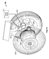
- FIG. 2 shows an exemplary wheel assembly 200 for propelling an aircraft along a ground or surface using the methods disclosed herein.
- the wheel assembly 200 includes a landing strut 202 that extends from a body of an aircraft.
- the landing strut 202 is coupled to an axle 204 having at least one wheel 206a and 206b attached that rotates on the axle 204.
- tire 207b is shown disposed on wheel 206b while tire 207a, which is disposed on wheel 206a, is shown as transparent in order to show details of the ground propulsion apparatus of the present invention.
- the wheels 206a and 206b disposed on the axle 204 may rotate independently of each other.
- the wheel 206a may be coupled to exemplary ring gear 208 that receives a mechanical force that generates a rotation of the wheel 206a.
- wheel 206b may be coupled to a ring gear (not shown) to receive a mechanical force that generates a rotation of wheel 206b.
- the ring gear 208 may be coupled to an output pinion 210 of a transmission 212 which may be a hydrostatic transmission.
- the output pinion 210 and the ring gear 208 may mesh together in order to form a coupling to transfer a rotation from the output pinion 210 to the ring gear 208a and to wheel 206a.
- motor 214 is coupled to transmission 212 in order to generate a mechanical motion to activate the transmission 212.
- the motor 214 may be a constant velocity motor that may be coupled directly (i.e., without any intervening electronics) to the power supply of the aircraft such as power supply 110 via power line 216.
- the motor 214 may be a line start motor in an exemplary embodiment.
- the motor 214 Upon being energized by the power supply 110, the motor 214 produces a constant rotation of its rotor (not shown).
- the transmission 212 receives the constant rotation of the rotor and generates as output a variable rotation of output pinion 210 which generates rotation of wheel 206a.
- a motor (not shown) and transmission may be coupled to wheel 206b to generate rotation of wheel 206b for ground propulsion using the methods disclosed herein with respect to wheel 206a.
- power from the power supply may be sent to an AC-to-DC converter which outputs a DC voltage.
- the DC voltage is input to an inverter and thus converted from DC voltage to a variable AC voltage.
- the variable voltage output by the inverter is provided to the motor and generates a variable speed at the motor.
- the additional electronics i.e., the AC/DC converter and inverter of the known systems of ground propulsion, add weight and complexity.
- the motor 214 is directly coupled to the power supply 110 and generates a constant speed when energized and thus does not utilize the intervening AC-to-DC converter and inverter. While the motor 214 is directly coupled to the power supply 110, the system may include contactors or switches to disconnect the motor 214 from the power supply 110 or may include a filter that prevents the motor 214 from disturbing power quality at the power supply 110.
- the motor may be disposed at the wheel location and integrated with the transmission at the wheel location.
- the transmission may be a hydrostatic transmission that may convert the constant-speed rotation of the motor to a variable-speed rotation that may be provided to the wheel for ground propulsion.
- the hydrostatic transmission may also include one or more gears stages in order to reduce the size of the hydrostatic transmission component.
- the integrated motor and transmission may be assembled to the wheel assembly 200 and/or landing strut 202 during manufacture of the wheel assembly 200. In alternate embodiments, the integrated motor and transmission may be attached to a pre-existing strut in order to retrofit an aircraft.
Abstract
Description
- The present invention relates to ground propulsion for an aircraft and, more specifically, to a method and apparatus for taxiing an aircraft.
- Aircraft generally taxi along a runway using propulsion provided from the aircraft engines. However, using the aircraft engines for the purpose of taxiing expends large amounts of fuel. In addition, particles from the ground can easily be swept into the engines during taxiing and cause damage to the engine.
- According to one embodiment of the present invention, an apparatus for ground propulsion of an object includes: a motor disposed at a location of a wheel of the object configured to draw electrical power directly from a power supply and generate a constant mechanical motion; and a transmission configured to receive the constant mechanical motion and generate a variable mechanical motion at the wheel to propel the object.
- According to another embodiment of the present invention, a ground propulsion system for an aircraft includes: a wheel; a motor coupled configured to receive electrical power received directly from a power supply and generate a constant mechanical motion; and a transmission configured to receive the constant mechanical motion and generate a variable mechanical motion at the wheel to propel the aircraft.
- According to another embodiment of the present invention, a method of propelling an object across a surface includes: generating a constant rotation at a motor disposed at a wheel of the object; receiving the constant rotation at a transmission to generate a variable rotation; and transferring the variable rotation from the transmission to a wheel to propel the object across the surface.
- Additional features and advantages are realized through the techniques of the present invention. Other embodiments and aspects of the invention are described in detail herein and are considered a part of the claimed invention. For a better understanding of the invention with the advantages and the features, refer to the description and to the drawings.
- The subject matter which is regarded as the invention is particularly pointed out and distinctly claimed in the claims at the conclusion of the specification. The forgoing and other features, and advantages of the invention are apparent from the following detailed description taken in conjunction with the accompanying drawings in which:
-
Figure 1 shows a schematic diagram of a system for providing ground propulsion of an object; and -
Figure 2 shows an exemplary wheel assembly for propelling an aircraft along a ground or surface using the methods disclosed herein. -
Figure 1 shows a schematic diagram of asystem 100 for providing ground propulsion of an object. In an exemplary embodiment, the object may be an aircraft and ground propulsion of the aircraft may refer to a taxiing operation of the aircraft across a runway. Theexemplary system 100 includes variousaircraft body components 102 that are disposed within a body of the aircraft and various components of awheel assembly 104 that are disposed at a wheel location extended from the body of the aircraft. Theaircraft body components 102 may include for example, apower supply 110, such as an aircraft electrical bus. In various embodiments,power supply 110 may provide alternating current at about 400 Hertz and about 115 volts (115 V AC) or 230 V AC. Power from thepower supply 110 is supplied to components of thewheel assembly 104 overpower lines aircraft body components 102 may include a control andmonitoring system 112 that controls and monitors various operations that occur at thewheel assembly 104. The control andmonitoring system 112 may receive various orders and activation commands from acommand unit 114. In addition, the control andmonitoring system 112 may provide various measurements to thecommand unit 114. Thecommand unit 114 may include a processor or a manual system operated, for example, by a pilot of the aircraft. - The
wheel assembly 104 may include one ormore motors more transmissions disengagement systems more wheels wheel 126a-d may be coupled to acorresponding motor 120a-d andtransmission 122a-d. Motors 120a-d receive electrical power from thepower supply 110 overtransmission lines 116a-d, respectively. In various embodiments, at least one of themotors 120a-d may be a motor that may be connected directly to thepower supply 110 and that generates a constant mechanical rotation of its rotor when energized by thepower supply 110. Themotors 120a-d may include at least one line start motor in an exemplary embodiment.Transmissions 122a-d receive the constant mechanical motion generated at theirrespective motors 120a-d and convert the received constant mechanical motion to a variable mechanical motion that may be used to generate rotation ofwheels 126a-d. Engagement/disengagement system 124a may be operated to form or disrupt a coupling of thetransmissions wheels Wheels disengagement system 124b may be operated to form or disrupt a coupling of thetransmissions wheels Wheels disengagement systems exemplary power line 130 and may be monitored and controlled by the control andmonitoring system 112 overexemplary command line 132. Additionally,wheels 126a-d may be coupled to wheelrotation measurement devices 128a-d which provide feedback on the wheel rotation to the control andmonitoring system 112. The wheelrotation measurement devices 128a-d may be powered overexemplary power line 134 and monitored and controlled by the control andmonitoring system 112 overexemplary command line 136. The control andmonitoring system 112 may thus be used to control atransmissions 122a-d to rotate thewheels 126a-d at selected rotation rates. -
Figure 2 shows anexemplary wheel assembly 200 for propelling an aircraft along a ground or surface using the methods disclosed herein. Thewheel assembly 200 includes alanding strut 202 that extends from a body of an aircraft. Thelanding strut 202 is coupled to anaxle 204 having at least onewheel 206a and 206b attached that rotates on theaxle 204. In the illustration ofFigure 2 ,tire 207b is shown disposed on wheel 206b whiletire 207a, which is disposed onwheel 206a, is shown as transparent in order to show details of the ground propulsion apparatus of the present invention. In an exemplary embodiment, thewheels 206a and 206b disposed on theaxle 204 may rotate independently of each other. In the exemplary embodiment, thewheel 206a may be coupled toexemplary ring gear 208 that receives a mechanical force that generates a rotation of thewheel 206a. Similarly, wheel 206b may be coupled to a ring gear (not shown) to receive a mechanical force that generates a rotation of wheel 206b. Referring towheel 206a, thering gear 208 may be coupled to anoutput pinion 210 of atransmission 212 which may be a hydrostatic transmission. Theoutput pinion 210 and thering gear 208 may mesh together in order to form a coupling to transfer a rotation from theoutput pinion 210 to the ring gear 208a and towheel 206a. In various embodiments,motor 214 is coupled totransmission 212 in order to generate a mechanical motion to activate thetransmission 212. Themotor 214 may be a constant velocity motor that may be coupled directly (i.e., without any intervening electronics) to the power supply of the aircraft such aspower supply 110 via power line 216. Themotor 214 may be a line start motor in an exemplary embodiment. Upon being energized by thepower supply 110, themotor 214 produces a constant rotation of its rotor (not shown). Thetransmission 212 receives the constant rotation of the rotor and generates as output a variable rotation ofoutput pinion 210 which generates rotation ofwheel 206a. Similarly, a motor (not shown) and transmission (not shown) may be coupled to wheel 206b to generate rotation of wheel 206b for ground propulsion using the methods disclosed herein with respect towheel 206a. - In known systems for ground propulsion, power from the power supply may be sent to an AC-to-DC converter which outputs a DC voltage. The DC voltage is input to an inverter and thus converted from DC voltage to a variable AC voltage. The variable voltage output by the inverter is provided to the motor and generates a variable speed at the motor. The additional electronics (i.e., the AC/DC converter and inverter) of the known systems of ground propulsion, add weight and complexity.
- In one embodiment of the present invention, the
motor 214 is directly coupled to thepower supply 110 and generates a constant speed when energized and thus does not utilize the intervening AC-to-DC converter and inverter. While themotor 214 is directly coupled to thepower supply 110, the system may include contactors or switches to disconnect themotor 214 from thepower supply 110 or may include a filter that prevents themotor 214 from disturbing power quality at thepower supply 110. The motor may be disposed at the wheel location and integrated with the transmission at the wheel location. The transmission may be a hydrostatic transmission that may convert the constant-speed rotation of the motor to a variable-speed rotation that may be provided to the wheel for ground propulsion. The hydrostatic transmission may also include one or more gears stages in order to reduce the size of the hydrostatic transmission component. In various embodiments, the integrated motor and transmission may be assembled to thewheel assembly 200 and/orlanding strut 202 during manufacture of thewheel assembly 200. In alternate embodiments, the integrated motor and transmission may be attached to a pre-existing strut in order to retrofit an aircraft. - The terminology used herein is for the purpose of describing particular embodiments only and is not intended to be limiting of the invention. As used herein, the singular forms "a", "an" and "the" are intended to include the plural forms as well, unless the context clearly indicates otherwise. It will be further understood that the terms "comprises" and/or "comprising," when used in this specification, specify the presence of stated features, integers, steps, operations, elements, and/or components, but do not preclude the presence or addition of one more other features, integers, steps, operations, element components, and/or groups thereof.
- The corresponding structures, materials, acts, and equivalents of all means or step plus function elements in the claims below are intended to include any structure, material, or act for performing the function in combination with other claimed elements as specifically claimed. The description of the present invention has been presented for purposes of illustration and description, but is not intended to be exhaustive or limited to the invention in the form disclosed. Many modifications and variations will be apparent to those of ordinary skill in the art without departing from the scope of the invention. The embodiment was chosen and described in order to best explain the principles of the invention and the practical application, and to enable others of ordinary skill in the art to understand the invention for various embodiments with various modifications as are suited to the particular use contemplated
- While the preferred embodiment to the invention had been described, it will be understood that those skilled in the art, both now and in the future, may make various improvements and enhancements which fall within the scope of the claims which follow. These claims should be construed to maintain the proper protection for the invention first described.
Claims (15)
- An apparatus for ground propulsion of an aircraft, comprising:a motor (214) disposed at a location of a wheel (206a) of the aircraft that draws electrical power directly from a power supply (110) and generates a constant mechanical motion; anda transmission (212) that receives the constant mechanical motion and generates a variable mechanical motion at the wheel (206a) to propel the aircraft.
- The apparatus of claim 1 wherein the power supply (110) is an auxiliary power supply located within a body of the aircraft.
- The apparatus of claim 1 or 2, wherein the motor (214) is disposed at a location extended from a body of the aircraft.
- The apparatus of any of claims 1 to 3, further comprising a control and monitoring system (212) configured to control the transmission (212) to generate the variable mechanical motion at the wheel (206a) at a selected rotation rate.
- The apparatus of any preceding claim, wherein the transmission (212) further comprises a hydrostatic transmission.
- The apparatus of any preceding claim, wherein the motor (214) is integrated with the transmission (212).
- The apparatus of any preceding claim, wherein the motor (214) is a line start motor.
- A method of propelling an aircraft across a surface, comprising:generating a constant rotation at a motor (214) disposed at a wheel (206a) of the aircraft;receiving the constant rotation at a transmission (212) to generate a variable rotation; andtransferring the variable rotation from the transmission (212) to a wheel (206a) to propel the aircraft across the surface.
- The method of claim 8, further comprising generating the constant rotation at the motor (214) using electrical power.
- The method of claim 9, further comprising supplying the electrical power for generating the constant rotation at the motor (214) directly from an auxiliary power supply (110) located within a body of the aircraft.
- The method of any of claims 8 to 10, further comprising disposing the motor (214) at a location extended from a body of the aircraft.
- The method of any of claims 8 to 11, further comprising a control and monitoring system (112) configured to control the transmission (212) to generate the variable mechanical motion at the wheel (206a) at a selected rotation rate.
- The method of any of claims 8 to 12, wherein the transmission (212) further comprises a hydrostatic transmission.
- The method of any of claims 8 to 13, wherein the motor (214) is integrated with the transmission (210).
- The method of any of claims 8 to 14, wherein the motor (214) is a line start motor.
Applications Claiming Priority (1)
| Application Number | Priority Date | Filing Date | Title |
|---|---|---|---|
| US13/903,509 US9139291B2 (en) | 2013-05-28 | 2013-05-28 | Integrated hydrostatic transmission for electronic taxiing operations |
Publications (2)
| Publication Number | Publication Date |
|---|---|
| EP2808252A1 true EP2808252A1 (en) | 2014-12-03 |
| EP2808252B1 EP2808252B1 (en) | 2017-08-16 |
Family
ID=50735949
Family Applications (1)
| Application Number | Title | Priority Date | Filing Date |
|---|---|---|---|
| EP14169147.7A Active EP2808252B1 (en) | 2013-05-28 | 2014-05-20 | Integrated hydrostatic transmission for electronic taxiing operations |
Country Status (2)
| Country | Link |
|---|---|
| US (1) | US9139291B2 (en) |
| EP (1) | EP2808252B1 (en) |
Families Citing this family (5)
| Publication number | Priority date | Publication date | Assignee | Title |
|---|---|---|---|---|
| FR2998870B1 (en) * | 2012-12-03 | 2015-01-09 | Michelin & Cie | WHEEL MOTORIZATION SYSTEM, IN PARTICULAR AN AIRCRAFT |
| FR3009277B1 (en) * | 2013-08-02 | 2017-11-03 | Messier Bugatti Dowty | AIRCRAFT IMPELLER EQUIPPED WITH A WHEEL DRIVE. |
| FR3011531B1 (en) * | 2013-10-04 | 2017-04-21 | Messier Bugatti Dowty | AIRCRAFT IMPELLER EQUIPPED WITH TRAINING MEANS FOR ROTATING WHEELS CARRIED BY THE LICENSOR |
| GB2524242A (en) * | 2014-03-17 | 2015-09-23 | Airbus Operations Ltd | Drive system for aircraft landing gear |
| EP3002213A1 (en) * | 2014-10-03 | 2016-04-06 | Goodrich Actuation Systems Ltd. | Aircraft taxiing system |
Citations (4)
| Publication number | Priority date | Publication date | Assignee | Title |
|---|---|---|---|---|
| EP2236419A2 (en) * | 2009-04-01 | 2010-10-06 | Rolls-Royce plc | An apparatus for taxiing an aircraft |
| US20110303785A1 (en) * | 2010-06-10 | 2011-12-15 | Messier-Bugatti-Dowty | Aircraft fitted with an independent drive device |
| US20120138734A1 (en) * | 2010-12-03 | 2012-06-07 | Bae Systems Controls, Inc. | Hydraulic ground propulsion system |
| EP2548802A2 (en) * | 2011-07-18 | 2013-01-23 | Airbus Operations S.L. | Aircraft versatile power system |
Family Cites Families (7)
| Publication number | Priority date | Publication date | Assignee | Title |
|---|---|---|---|---|
| US2376621A (en) * | 1944-09-14 | 1945-05-22 | Milton L Reed | Safety landing gear and wheel for airplanes |
| US3542318A (en) * | 1968-09-09 | 1970-11-24 | Ralph G Ellsworth | Apparatus for rotating aircraft wheels prior to landing |
| US3850389A (en) * | 1973-05-04 | 1974-11-26 | D Dixon | Landing gear wheel device for aircraft |
| GB0915009D0 (en) * | 2009-08-28 | 2009-09-30 | Airbus Operations Ltd | Aircraft landing gear |
| FR2954234B1 (en) * | 2009-12-17 | 2012-03-02 | Michelin Soc Tech | MOTORIZATION SYSTEM OF A WHEEL ASSOCIATED WITH A SUSPENSION |
| RU2529558C2 (en) * | 2010-04-28 | 2014-09-27 | Л-З Коммьюникейшнз Магнет-Мотор Гмбх | Aircraft undercarriage drive assembly |
| GB201214198D0 (en) * | 2012-08-08 | 2012-09-19 | Airbus Uk Ltd | Landing gear drive system |
-
2013
- 2013-05-28 US US13/903,509 patent/US9139291B2/en active Active
-
2014
- 2014-05-20 EP EP14169147.7A patent/EP2808252B1/en active Active
Patent Citations (4)
| Publication number | Priority date | Publication date | Assignee | Title |
|---|---|---|---|---|
| EP2236419A2 (en) * | 2009-04-01 | 2010-10-06 | Rolls-Royce plc | An apparatus for taxiing an aircraft |
| US20110303785A1 (en) * | 2010-06-10 | 2011-12-15 | Messier-Bugatti-Dowty | Aircraft fitted with an independent drive device |
| US20120138734A1 (en) * | 2010-12-03 | 2012-06-07 | Bae Systems Controls, Inc. | Hydraulic ground propulsion system |
| EP2548802A2 (en) * | 2011-07-18 | 2013-01-23 | Airbus Operations S.L. | Aircraft versatile power system |
Also Published As
| Publication number | Publication date |
|---|---|
| US9139291B2 (en) | 2015-09-22 |
| US20140353423A1 (en) | 2014-12-04 |
| EP2808252B1 (en) | 2017-08-16 |
Similar Documents
| Publication | Publication Date | Title |
|---|---|---|
| EP2808252B1 (en) | Integrated hydrostatic transmission for electronic taxiing operations | |
| US8517303B2 (en) | Integrated multifunctional powered wheel system for aircraft | |
| US9873518B2 (en) | Electrical architecture for an aircraft, an aircraft, and a method of using it | |
| EP3375713A1 (en) | Emergency power generation via electrically driven tail cone boundary layer ingestion thruster | |
| CN102795344B (en) | The method of power is provided to the autonomous CD-ROM drive motor of aircraft | |
| CN101941524B (en) | Method of taxiing aircraft | |
| US10759545B2 (en) | Hybrid electric aircraft system with distributed propulsion | |
| EP3095693B1 (en) | Aircraft steering system | |
| US5899411A (en) | Aircraft electrical system providing emergency power and electric starting of propulsion engines | |
| JP5955960B2 (en) | Equipment for supplying power to ground aircraft | |
| EP2236419B1 (en) | An apparatus for taxiing an aircraft | |
| US10906657B2 (en) | Aircraft system with distributed propulsion | |
| US9227725B2 (en) | Aircraft including an electric starter-generator for the or each turbojet, an undercarriage fitted with an electric motor for taxiing, an electricity converter, and an electricity distribution unit connecting the electricity converter to the starter-generator and the electric motor | |
| JP6626328B2 (en) | Electric taxiing system for aircraft | |
| JP2015514036A (en) | Equipment for supplying power to ground aircraft | |
| JP2020001691A (en) | Electrical architecture for aircraft, aircraft comprising the architecture, and method for operating the architecture | |
| US11300001B2 (en) | Electrical system for aircraft | |
| CN106741863B (en) | The high-lift system of aircraft | |
| CN117242004A (en) | Flying device | |
| EP3118108A1 (en) | Aircraft landing gear | |
| ITUB20150241A1 (en) | CONTROL SYSTEM FOR A MOTOR AIRCRAFT, PARTICULARLY SUITABLE FOR THE MANAGEMENT OF ENGINE FAILURES, AS WELL AS THE RESPECTIVE METHOD OF OPERATION |
Legal Events
| Date | Code | Title | Description |
|---|---|---|---|
| PUAI | Public reference made under article 153(3) epc to a published international application that has entered the european phase |
Free format text: ORIGINAL CODE: 0009012 |
|
| 17P | Request for examination filed |
Effective date: 20140520 |
|
| AK | Designated contracting states |
Kind code of ref document: A1 Designated state(s): AL AT BE BG CH CY CZ DE DK EE ES FI FR GB GR HR HU IE IS IT LI LT LU LV MC MK MT NL NO PL PT RO RS SE SI SK SM TR |
|
| AX | Request for extension of the european patent |
Extension state: BA ME |
|
| R17P | Request for examination filed (corrected) |
Effective date: 20150603 |
|
| RBV | Designated contracting states (corrected) |
Designated state(s): AL AT BE BG CH CY CZ DE DK EE ES FI FR GB GR HR HU IE IS IT LI LT LU LV MC MK MT NL NO PL PT RO RS SE SI SK SM TR |
|
| GRAP | Despatch of communication of intention to grant a patent |
Free format text: ORIGINAL CODE: EPIDOSNIGR1 |
|
| INTG | Intention to grant announced |
Effective date: 20170223 |
|
| RIN1 | Information on inventor provided before grant (corrected) |
Inventor name: HIMMELMANN, RICHARD A. |
|
| GRAS | Grant fee paid |
Free format text: ORIGINAL CODE: EPIDOSNIGR3 |
|
| GRAA | (expected) grant |
Free format text: ORIGINAL CODE: 0009210 |
|
| AK | Designated contracting states |
Kind code of ref document: B1 Designated state(s): AL AT BE BG CH CY CZ DE DK EE ES FI FR GB GR HR HU IE IS IT LI LT LU LV MC MK MT NL NO PL PT RO RS SE SI SK SM TR |
|
| REG | Reference to a national code |
Ref country code: GB Ref legal event code: FG4D |
|
| REG | Reference to a national code |
Ref country code: CH Ref legal event code: EP |
|
| REG | Reference to a national code |
Ref country code: IE Ref legal event code: FG4D |
|
| REG | Reference to a national code |
Ref country code: AT Ref legal event code: REF Ref document number: 918767 Country of ref document: AT Kind code of ref document: T Effective date: 20170915 |
|
| REG | Reference to a national code |
Ref country code: DE Ref legal event code: R096 Ref document number: 602014013104 Country of ref document: DE |
|
| REG | Reference to a national code |
Ref country code: NL Ref legal event code: MP Effective date: 20170816 |
|
| REG | Reference to a national code |
Ref country code: LT Ref legal event code: MG4D |
|
| REG | Reference to a national code |
Ref country code: AT Ref legal event code: MK05 Ref document number: 918767 Country of ref document: AT Kind code of ref document: T Effective date: 20170816 |
|
| PG25 | Lapsed in a contracting state [announced via postgrant information from national office to epo] |
Ref country code: LT Free format text: LAPSE BECAUSE OF FAILURE TO SUBMIT A TRANSLATION OF THE DESCRIPTION OR TO PAY THE FEE WITHIN THE PRESCRIBED TIME-LIMIT Effective date: 20170816 Ref country code: NL Free format text: LAPSE BECAUSE OF FAILURE TO SUBMIT A TRANSLATION OF THE DESCRIPTION OR TO PAY THE FEE WITHIN THE PRESCRIBED TIME-LIMIT Effective date: 20170816 Ref country code: AT Free format text: LAPSE BECAUSE OF FAILURE TO SUBMIT A TRANSLATION OF THE DESCRIPTION OR TO PAY THE FEE WITHIN THE PRESCRIBED TIME-LIMIT Effective date: 20170816 Ref country code: NO Free format text: LAPSE BECAUSE OF FAILURE TO SUBMIT A TRANSLATION OF THE DESCRIPTION OR TO PAY THE FEE WITHIN THE PRESCRIBED TIME-LIMIT Effective date: 20171116 Ref country code: FI Free format text: LAPSE BECAUSE OF FAILURE TO SUBMIT A TRANSLATION OF THE DESCRIPTION OR TO PAY THE FEE WITHIN THE PRESCRIBED TIME-LIMIT Effective date: 20170816 Ref country code: SE Free format text: LAPSE BECAUSE OF FAILURE TO SUBMIT A TRANSLATION OF THE DESCRIPTION OR TO PAY THE FEE WITHIN THE PRESCRIBED TIME-LIMIT Effective date: 20170816 |
|
| PG25 | Lapsed in a contracting state [announced via postgrant information from national office to epo] |
Ref country code: LV Free format text: LAPSE BECAUSE OF FAILURE TO SUBMIT A TRANSLATION OF THE DESCRIPTION OR TO PAY THE FEE WITHIN THE PRESCRIBED TIME-LIMIT Effective date: 20170816 Ref country code: BG Free format text: LAPSE BECAUSE OF FAILURE TO SUBMIT A TRANSLATION OF THE DESCRIPTION OR TO PAY THE FEE WITHIN THE PRESCRIBED TIME-LIMIT Effective date: 20171116 Ref country code: IS Free format text: LAPSE BECAUSE OF FAILURE TO SUBMIT A TRANSLATION OF THE DESCRIPTION OR TO PAY THE FEE WITHIN THE PRESCRIBED TIME-LIMIT Effective date: 20171216 Ref country code: RS Free format text: LAPSE BECAUSE OF FAILURE TO SUBMIT A TRANSLATION OF THE DESCRIPTION OR TO PAY THE FEE WITHIN THE PRESCRIBED TIME-LIMIT Effective date: 20170816 Ref country code: PL Free format text: LAPSE BECAUSE OF FAILURE TO SUBMIT A TRANSLATION OF THE DESCRIPTION OR TO PAY THE FEE WITHIN THE PRESCRIBED TIME-LIMIT Effective date: 20170816 Ref country code: ES Free format text: LAPSE BECAUSE OF FAILURE TO SUBMIT A TRANSLATION OF THE DESCRIPTION OR TO PAY THE FEE WITHIN THE PRESCRIBED TIME-LIMIT Effective date: 20170816 Ref country code: GR Free format text: LAPSE BECAUSE OF FAILURE TO SUBMIT A TRANSLATION OF THE DESCRIPTION OR TO PAY THE FEE WITHIN THE PRESCRIBED TIME-LIMIT Effective date: 20171117 |
|
| REG | Reference to a national code |
Ref country code: FR Ref legal event code: PLFP Year of fee payment: 5 |
|
| PG25 | Lapsed in a contracting state [announced via postgrant information from national office to epo] |
Ref country code: DK Free format text: LAPSE BECAUSE OF FAILURE TO SUBMIT A TRANSLATION OF THE DESCRIPTION OR TO PAY THE FEE WITHIN THE PRESCRIBED TIME-LIMIT Effective date: 20170816 Ref country code: CZ Free format text: LAPSE BECAUSE OF FAILURE TO SUBMIT A TRANSLATION OF THE DESCRIPTION OR TO PAY THE FEE WITHIN THE PRESCRIBED TIME-LIMIT Effective date: 20170816 Ref country code: RO Free format text: LAPSE BECAUSE OF FAILURE TO SUBMIT A TRANSLATION OF THE DESCRIPTION OR TO PAY THE FEE WITHIN THE PRESCRIBED TIME-LIMIT Effective date: 20170816 |
|
| REG | Reference to a national code |
Ref country code: DE Ref legal event code: R097 Ref document number: 602014013104 Country of ref document: DE |
|
| PG25 | Lapsed in a contracting state [announced via postgrant information from national office to epo] |
Ref country code: IT Free format text: LAPSE BECAUSE OF FAILURE TO SUBMIT A TRANSLATION OF THE DESCRIPTION OR TO PAY THE FEE WITHIN THE PRESCRIBED TIME-LIMIT Effective date: 20170816 Ref country code: EE Free format text: LAPSE BECAUSE OF FAILURE TO SUBMIT A TRANSLATION OF THE DESCRIPTION OR TO PAY THE FEE WITHIN THE PRESCRIBED TIME-LIMIT Effective date: 20170816 Ref country code: SM Free format text: LAPSE BECAUSE OF FAILURE TO SUBMIT A TRANSLATION OF THE DESCRIPTION OR TO PAY THE FEE WITHIN THE PRESCRIBED TIME-LIMIT Effective date: 20170816 Ref country code: SK Free format text: LAPSE BECAUSE OF FAILURE TO SUBMIT A TRANSLATION OF THE DESCRIPTION OR TO PAY THE FEE WITHIN THE PRESCRIBED TIME-LIMIT Effective date: 20170816 |
|
| PLBE | No opposition filed within time limit |
Free format text: ORIGINAL CODE: 0009261 |
|
| STAA | Information on the status of an ep patent application or granted ep patent |
Free format text: STATUS: NO OPPOSITION FILED WITHIN TIME LIMIT |
|
| 26N | No opposition filed |
Effective date: 20180517 |
|
| PG25 | Lapsed in a contracting state [announced via postgrant information from national office to epo] |
Ref country code: SI Free format text: LAPSE BECAUSE OF FAILURE TO SUBMIT A TRANSLATION OF THE DESCRIPTION OR TO PAY THE FEE WITHIN THE PRESCRIBED TIME-LIMIT Effective date: 20170816 |
|
| REG | Reference to a national code |
Ref country code: DE Ref legal event code: R119 Ref document number: 602014013104 Country of ref document: DE |
|
| REG | Reference to a national code |
Ref country code: CH Ref legal event code: PL |
|
| REG | Reference to a national code |
Ref country code: BE Ref legal event code: MM Effective date: 20180531 |
|
| PG25 | Lapsed in a contracting state [announced via postgrant information from national office to epo] |
Ref country code: MC Free format text: LAPSE BECAUSE OF FAILURE TO SUBMIT A TRANSLATION OF THE DESCRIPTION OR TO PAY THE FEE WITHIN THE PRESCRIBED TIME-LIMIT Effective date: 20170816 |
|
| REG | Reference to a national code |
Ref country code: IE Ref legal event code: MM4A |
|
| PG25 | Lapsed in a contracting state [announced via postgrant information from national office to epo] |
Ref country code: CH Free format text: LAPSE BECAUSE OF NON-PAYMENT OF DUE FEES Effective date: 20180531 Ref country code: LI Free format text: LAPSE BECAUSE OF NON-PAYMENT OF DUE FEES Effective date: 20180531 |
|
| PG25 | Lapsed in a contracting state [announced via postgrant information from national office to epo] |
Ref country code: LU Free format text: LAPSE BECAUSE OF NON-PAYMENT OF DUE FEES Effective date: 20180520 |
|
| PG25 | Lapsed in a contracting state [announced via postgrant information from national office to epo] |
Ref country code: IE Free format text: LAPSE BECAUSE OF NON-PAYMENT OF DUE FEES Effective date: 20180520 Ref country code: DE Free format text: LAPSE BECAUSE OF NON-PAYMENT OF DUE FEES Effective date: 20181201 |
|
| PG25 | Lapsed in a contracting state [announced via postgrant information from national office to epo] |
Ref country code: BE Free format text: LAPSE BECAUSE OF NON-PAYMENT OF DUE FEES Effective date: 20180531 |
|
| PG25 | Lapsed in a contracting state [announced via postgrant information from national office to epo] |
Ref country code: MT Free format text: LAPSE BECAUSE OF NON-PAYMENT OF DUE FEES Effective date: 20180520 |
|
| PG25 | Lapsed in a contracting state [announced via postgrant information from national office to epo] |
Ref country code: TR Free format text: LAPSE BECAUSE OF FAILURE TO SUBMIT A TRANSLATION OF THE DESCRIPTION OR TO PAY THE FEE WITHIN THE PRESCRIBED TIME-LIMIT Effective date: 20170816 |
|
| PG25 | Lapsed in a contracting state [announced via postgrant information from national office to epo] |
Ref country code: PT Free format text: LAPSE BECAUSE OF FAILURE TO SUBMIT A TRANSLATION OF THE DESCRIPTION OR TO PAY THE FEE WITHIN THE PRESCRIBED TIME-LIMIT Effective date: 20170816 Ref country code: HU Free format text: LAPSE BECAUSE OF FAILURE TO SUBMIT A TRANSLATION OF THE DESCRIPTION OR TO PAY THE FEE WITHIN THE PRESCRIBED TIME-LIMIT; INVALID AB INITIO Effective date: 20140520 |
|
| PG25 | Lapsed in a contracting state [announced via postgrant information from national office to epo] |
Ref country code: CY Free format text: LAPSE BECAUSE OF FAILURE TO SUBMIT A TRANSLATION OF THE DESCRIPTION OR TO PAY THE FEE WITHIN THE PRESCRIBED TIME-LIMIT Effective date: 20170816 Ref country code: HR Free format text: LAPSE BECAUSE OF FAILURE TO SUBMIT A TRANSLATION OF THE DESCRIPTION OR TO PAY THE FEE WITHIN THE PRESCRIBED TIME-LIMIT Effective date: 20170816 Ref country code: MK Free format text: LAPSE BECAUSE OF NON-PAYMENT OF DUE FEES Effective date: 20170816 |
|
| PG25 | Lapsed in a contracting state [announced via postgrant information from national office to epo] |
Ref country code: AL Free format text: LAPSE BECAUSE OF FAILURE TO SUBMIT A TRANSLATION OF THE DESCRIPTION OR TO PAY THE FEE WITHIN THE PRESCRIBED TIME-LIMIT Effective date: 20170816 |
|
| P01 | Opt-out of the competence of the unified patent court (upc) registered |
Effective date: 20230522 |
|
| PGFP | Annual fee paid to national office [announced via postgrant information from national office to epo] |
Ref country code: FR Payment date: 20230420 Year of fee payment: 10 |
|
| PGFP | Annual fee paid to national office [announced via postgrant information from national office to epo] |
Ref country code: GB Payment date: 20230420 Year of fee payment: 10 |