EP2808192A1 - Open roof construction for a vehicle, and panel for use therein - Google Patents
Open roof construction for a vehicle, and panel for use therein Download PDFInfo
- Publication number
- EP2808192A1 EP2808192A1 EP13169849.0A EP13169849A EP2808192A1 EP 2808192 A1 EP2808192 A1 EP 2808192A1 EP 13169849 A EP13169849 A EP 13169849A EP 2808192 A1 EP2808192 A1 EP 2808192A1
- Authority
- EP
- European Patent Office
- Prior art keywords
- panel
- vessel
- space
- roof construction
- open roof
- Prior art date
- Legal status (The legal status is an assumption and is not a legal conclusion. Google has not performed a legal analysis and makes no representation as to the accuracy of the status listed.)
- Granted
Links
Images


Classifications
-
- B—PERFORMING OPERATIONS; TRANSPORTING
- B60—VEHICLES IN GENERAL
- B60J—WINDOWS, WINDSCREENS, NON-FIXED ROOFS, DOORS, OR SIMILAR DEVICES FOR VEHICLES; REMOVABLE EXTERNAL PROTECTIVE COVERINGS SPECIALLY ADAPTED FOR VEHICLES
- B60J7/00—Non-fixed roofs; Roofs with movable panels, e.g. rotary sunroofs
- B60J7/02—Non-fixed roofs; Roofs with movable panels, e.g. rotary sunroofs of sliding type, e.g. comprising guide shoes
- B60J7/04—Non-fixed roofs; Roofs with movable panels, e.g. rotary sunroofs of sliding type, e.g. comprising guide shoes with rigid plate-like element or elements, e.g. open roofs with harmonica-type folding rigid panels
-
- B—PERFORMING OPERATIONS; TRANSPORTING
- B60—VEHICLES IN GENERAL
- B60J—WINDOWS, WINDSCREENS, NON-FIXED ROOFS, DOORS, OR SIMILAR DEVICES FOR VEHICLES; REMOVABLE EXTERNAL PROTECTIVE COVERINGS SPECIALLY ADAPTED FOR VEHICLES
- B60J7/00—Non-fixed roofs; Roofs with movable panels, e.g. rotary sunroofs
- B60J7/0007—Non-fixed roofs; Roofs with movable panels, e.g. rotary sunroofs moveable head-liners, screens, curtains or blinds for ceilings
Definitions
- the invention relates to an open roof construction for a vehicle having an opening in its fixed roof, comprising a stationary part and at least a panel supported by the stationary part and adapted to close the opening in the fixed roof, said panel including two substantially parallel sheets connected and sealed to each other at least along their circumference in order to create a space therebetween containing gas.
- Such open roof constructions are known, for example from DE19943243 .
- the space between the panel sheets can be used for example for integrating a shading means into the panel, e.g. electronic or mechanical shading means. Due to different circumstances under which the vehicle should operate, e.g. different weather conditions or altitudes, different speeds and the like, the relative pressure between the space and the surrounding can change considerably. Due to these pressure differences, the panel sheet(s) can deform thereby jeopardizing the correct operation of the shading means.
- said space communicates with a device equalizing the pressure in the space with the ambient pressure.
- the pressure difference can be reduced or eliminated, thereby also reducing or eliminating the deformation of the panel sheet(s).
- the device comprises a controlling vessel regulating the pressure in the space and closing off said space from the environment.
- the closed volume in the controlling vessel that is communicating with the space in the panel may be variable, for example when the controlling vessel includes two vessel spaces separated by a movable wall, one vessel space communicating with the space between the sheets, the other vessel space communicating with the ambient air. This is a simple way of equalizing the pressure.
- the movable wall is a deformable membrane. This obviates the need for a sliding seal as there are no surfaces moving relatively.
- the controlling vessel may be provided in or on the stationary part.
- the controlling vessel may for example communicate with the space between the sheets of the panel through a flexible hose. This is for example useful if the (local) movements between the panel and the vessel are relatively small.
- the controlling vessel may communicate with the space between the sheets of the panel through a coupling having a valve opening and closing respectively when the panel is coupled or uncoupled from the controlling vessel.
- the movements of the panel are unlimited.
- the balancing device is then not active all the time, it is able to balance the pressure once the panel is closed. If there is a shading means between the panel sheets, it will normally only be used if the panel is in the closed position.
- the controlling vessel may be arranged at the rear edge of the roof opening, especially if the panel is movable at least between the closed position and a venting position in which a rear edge of the panel is raised.
- the panel is provided with a reinforcement and the device is combined with or even be integrated in the reinforcement, preferably on the front and/or rear side of the panel.
- the controlling vessel may be elongated and may extend in transverse direction, as this will facilitate integration in the reinforcement of the panel.
- the membrane in the controlling vessel may extend substantially parallel to the elongated direction of the controlling vessel, such that the vessel is divided in a top and bottom, or front and rear vessel spaces, or the membrane in the controlling vessel extends substantially perpendicularly to the elongated direction of the controlling vessel, so that the vessel is divided in left and right vessel spaces, or the membrane in the controlling vessel is an inflatable and deflatable balloon attached to a an outlet of the space between the panel sheets.
- the device comprises a dryer unit communicating with the environment, wherein the dryer unit may contain dehydrating material and preferably a filter.
- the dehydrating material may be replaceable or dehydradable, in order to be maintained so as to able to function through a long lifetime of the panel.
- the invention also includes a panel for use in an open roof construction as described above.
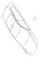
- a vehicle having an open roof construction in its fixed roof 2 is illustrated schematically.
- Said open roof construction comprises a roof opening 1 in a fixed roof 2 of the vehicle, such as a passenger car, and at least first and second closure panels 3, 4 for example glass or plastic, at least partly transparent panels as shown in Fig. 1 .
- the first and second closure panels can be moved for closing and at least partially opening said roof opening 1 by means which are known in the art and not described further here.
- an open roof system comprising the first and second movable panels 3, 4, connected via a moving mechanism (not shown here), which is known per se, to a stationary part 5, particularly a frame, and further comprising a motor and guiding channels (not shown).
- the stationary part 3 comprises front and rear members and a center member, which are known per se, and not further elucidated and are connected to lateral extrusion guides, and said stationary part 3 connects the open roof system with the body of the vehicle by means of the usual fixing concepts.
- Fig. 4 schematically shows a section of the roof.
- each panel 3, 4 is made up of an upper and lower panel sheet 3', 3" and 4', 4", respectively. These panel sheets are connected and sealed to each other along their circumference by a circumferential spacer 6 to form a space 7 within this circumferential spacer 6 and between the panel sheets.
- the upper panel sheet 3', 4' is larger than the lower panel sheet 3", 4", so that the spacer 6 is closer to the circumference of the lower panel sheet than to the circumference of the upper panel sheet.
- the dimensions of the upper panel sheets 3', 4' together substantially correspond to that of the roof opening 1 in the fixed roof 2, the dimensions of the lower panel sheet 3", 4" substantially correspond to openings 8, 9 in the stationary part 5 of the open roof construction. Other relative dimensions are conceivable.
- the space 7 within the panel may comprise shading means, either electronic or mechanical.
- Figs. 4 , 5 and 6 show a first embodiment of a device for balancing/equalizing the pressure between the space 7 and the environment.
- This device includes a vessel 10, which in this case is integrated in the panel 3, 4, in particular in a reinforcement 11 which is already present in the panel 3, 4.
- This reinforcement 11 is generally present around the circumference of the panel 3, 4, but especially on the front and rear side thereof.
- This vessel 10 can be present at the front or rear of the panel 3, 4 but also at the front and rear, as is illustrated in the drawings. It is elongated and extends in transverse direction. It is fixed to the panel outwardly of the spacer 6 below the upper panel sheet 3', 4'. It is spaced a short distance from the spacer 6, but it could also be integrated with it.
- One or more conduits 12 provide communication between the space 7 and the vessel 10 and extend through the spacer 6 in a sealed manner. If the vessel 10 and the spacer 6 are integrated, just one or more holes would suffice.
- the vessel 10 is divided in two vessel spaces 10A and 10B separated from each other by a movable wall, in this case by a deformable membrane 13.
- the vessel space 10A is communicating with the space 7 in the panel 3, 4, the vessel space 10B is communicating with the environment through a conduit 14.
- the membrane is gas-tight and can move under influence of pressure differences between the space 7 and the environment.
- the space 11 within the panels 3, 4 is completely closed-off from the environment, and thus this system is a closed system. It contains a gas suitable for its purpose, or just dry and clean air. If the pressure outside the panel 3, 4 is decreasing relatively (for example if the vehicle travels to a higher altitude), the volume of the gas inside the panel 3, 4 has a tendency to expand because the pressure therein remains constant.
- Fig. 7 shows a variation of the embodiment of Fig. 6 in that the membrane 13 does not divide the vessel 10 in an upper vessel space 10A and a lower vessel space 10B (due to the membrane edges being clamped between upper and lower vessel halves), but in an inner vessel space 10A and an outer vessel space 10B.
- the membrane is like a balloon or bag which can be inflated and deflated.
- the inner vessel space is connected to the conduit 12 communicating with the panel space 7.
- the function of the membrane 13 and vessel spaces 10A, 10B is similar to that of the former embodiments.
- the movement of the membrane or other movable wall should be sufficient to enable a volume change within the combined panel space 11 and vessel space 10A to allow the pressure in these spaces to follow the environmental pressure.
- Fig. 8 and 9 shows an embodiment of the device in which the vessel 10 is connected to the stationary part 3, in this case at a position between the rear edge of the front panel 3 and the front edge of the rear panel 4. It is accommodated in a transverse beam between the openings 8 and 9 in the stationary part 3.
- the rear panel 4 is adapted to move between a closed position within the roof opening 1 and a venting position in which its rear edge is raised.
- the front panel 3 can also move between closed and venting positions, but may also move from the venting position rearwardly, or make other movements.
- the front and rear panels 3, 4 use one common vessel 10 which is now of a larger volume.
- the communication between the space 7 in the rear panel 4 and the vessel space 10A is provided by a conduit which is now constructed as a flexible tube 16 allowing limited movements of the rear panel 4 with respect to the vessel 10.
- the communication between the vessel 10 and the space 7 in the front panel 3 is provided by a valve assembly 17 including a valve 18 in the vessel 10 and a valve 19 at the end of the conduit 12. Both valves 18, 19 close if the panel 3 moves away from the vessel 10, and both valves 18, 19 are opened if the panel valve 19 engages the vessel valve 18. In this manner no environmental air can enter the vessel and panel spaces 7, 10A, so that it remains a closed system. Balancing of pressures can only take place with the panel 3 in its closed position, but this hardly affects the effectiveness of the device. It might be automated to move the panel to the closed position if the pressure difference between space 7 and the environment rises above a certain level.
- Fig. 10 shows a further embodiment of the device which is now an open system, in which there is direct communication between the space 7 in the panels 3, 4 and the environment.
- the communication is only possible through a dryer unit 20.
- the dryer unit 20 comprises a container 21 containing dehydrating material 22, such as hydrogel, silica gel calcium chloride or the like, and possibly also a filter to keep out dust particles and other pollutions.
- the container 21 is combined with the panel reinforcement 11 of each panel 3, 4 such that the reinforcing strength thereof is not reduced.
- the container 21 is communicating with the space 7 within the panels 3, 4, respectively through one or more conduits 12 on the one hand and with the environment through one or more conduits 14 on the other hand. Communication between the conduits 12, 13 is only possible through the dehydrating material 22. Generally, the conduit 14 communicates with the interior of the vehicle, but could also communicate with the exterior of the vehicle. The dehydrating material should be reachable in order to be serviced, either by its replacement or by being dehydrated.
- the invention is not limited to the embodiments shown in the drawings and described above, and can be varied in different manners within the scope of the invention.
- the invention is also useful in fixed roof panels.
- the membrane could be replaced by another displaceable or deformable wall adapted to change the volume of the space with the panel.
- the vessel may be connected to or integrated in the panel in another way or in other positions.
- a part of the vessel is generally in open communication with the environment.
- the drying unit such as described above may be combined with the vessel.
Landscapes
- Engineering & Computer Science (AREA)
- Mechanical Engineering (AREA)
- Body Structure For Vehicles (AREA)
- Tents Or Canopies (AREA)
Abstract
Description
- The invention relates to an open roof construction for a vehicle having an opening in its fixed roof, comprising a stationary part and at least a panel supported by the stationary part and adapted to close the opening in the fixed roof, said panel including two substantially parallel sheets connected and sealed to each other at least along their circumference in order to create a space therebetween containing gas.
- Such open roof constructions are known, for example from
DE19943243 . The space between the panel sheets can be used for example for integrating a shading means into the panel, e.g. electronic or mechanical shading means. Due to different circumstances under which the vehicle should operate, e.g. different weather conditions or altitudes, different speeds and the like, the relative pressure between the space and the surrounding can change considerably. Due to these pressure differences, the panel sheet(s) can deform thereby jeopardizing the correct operation of the shading means. - It is one of the objects to provide a solution for, or at least reduce, this problem.
- According to an aspect of the invention, said space communicates with a device equalizing the pressure in the space with the ambient pressure.
- Due to this equalizing or balancing device, the pressure difference can be reduced or eliminated, thereby also reducing or eliminating the deformation of the panel sheet(s).
- In one embodiment, the device comprises a controlling vessel regulating the pressure in the space and closing off said space from the environment.
- Because the device closes off said space, this space is protected from dirt and moisture.
- The closed volume in the controlling vessel that is communicating with the space in the panel may be variable, for example when the controlling vessel includes two vessel spaces separated by a movable wall, one vessel space communicating with the space between the sheets, the other vessel space communicating with the ambient air. This is a simple way of equalizing the pressure.
- In one embodiment, the movable wall is a deformable membrane. This obviates the need for a sliding seal as there are no surfaces moving relatively.
- The controlling vessel may be provided in or on the stationary part. In that case, the controlling vessel may for example communicate with the space between the sheets of the panel through a flexible hose. This is for example useful if the (local) movements between the panel and the vessel are relatively small.
- In another embodiment, especially if the panel is a movable panel adapted to move between a closed position closing the roof opening and an open position releasing the roof opening at least partly, and if it comprises a drain channel arranged near an edge of the roof opening, the controlling vessel may communicate with the space between the sheets of the panel through a coupling having a valve opening and closing respectively when the panel is coupled or uncoupled from the controlling vessel.
- In this embodiment, the movements of the panel are unlimited. Although the balancing device is then not active all the time, it is able to balance the pressure once the panel is closed. If there is a shading means between the panel sheets, it will normally only be used if the panel is in the closed position.
- The controlling vessel may be arranged at the rear edge of the roof opening, especially if the panel is movable at least between the closed position and a venting position in which a rear edge of the panel is raised.
- In another embodiment, the panel is provided with a reinforcement and the device is combined with or even be integrated in the reinforcement, preferably on the front and/or rear side of the panel.
- In such embodiment, there is no need for a connection between the panel and the device at the stationary part, as the device will follow the panel with every movement.
- The controlling vessel may be elongated and may extend in transverse direction, as this will facilitate integration in the reinforcement of the panel.
- The membrane in the controlling vessel may extend substantially parallel to the elongated direction of the controlling vessel, such that the vessel is divided in a top and bottom, or front and rear vessel spaces, or the membrane in the controlling vessel extends substantially perpendicularly to the elongated direction of the controlling vessel, so that the vessel is divided in left and right vessel spaces, or the membrane in the controlling vessel is an inflatable and deflatable balloon attached to a an outlet of the space between the panel sheets.
- According to another aspect of the invention, the device comprises a dryer unit communicating with the environment, wherein the dryer unit may contain dehydrating material and preferably a filter.
- This is an open system, wherein there is a direct communication between the space within the panel and the environment, although only through the dryer unit which keeps the space within the panel dry and clean.
- The dehydrating material may be replaceable or dehydradable, in order to be maintained so as to able to function through a long lifetime of the panel.
- The invention also includes a panel for use in an open roof construction as described above.
- Further details and advantages of the open roof construction follow from the description below with reference to the attached drawings showing embodiments of the open roof construction by way of example.
-
Fig. 1 is a schematic perspective view of the upper part of a vehicle comprising an embodiment of the open roof construction. -
Fig. 2 is an enlarged perspective view of the open roof construction ofFig. 1 . -
Fig. 3 is a plan view of the left part of the open roof construction ofFig. 2 . -
Fig. 4 is a very schematic sectional view of the open roof construction according to the line IV-IV inFig. 3 . -
Fig. 5 is an enlarged sectional view of the open roof construction according to the line V-V inFig. 3 . -
Fig. 6 shows detail VI inFig. 5 on a larger scale. -
Fig. 7 is a view corresponding to that ofFig. 6 but showing a variation of the embodiment. -
Fig. 8 is an enlarged sectional view according to the line VIII-VIII inFig. 1 but showing an alternative embodiment of the device. -
Fig. 9 is a view corresponding to that ofFig. 8 , but showing the front panel in venting position. -
Fig. 10 is an enlarged sectional view corresponding to that ofFig. 6 , but showing an alternative embodiment of the device. - Referring to
Fig. 1 , a vehicle having an open roof construction in its fixed roof 2 is illustrated schematically. Said open roof construction comprises a roof opening 1 in a fixed roof 2 of the vehicle, such as a passenger car, and at least first andsecond closure panels Fig. 1 . The first and second closure panels can be moved for closing and at least partially opening said roof opening 1 by means which are known in the art and not described further here. - Referring to
Fig. 2 and3 , an open roof system is schematically illustrated, comprising the first and secondmovable panels stationary part 3 comprises front and rear members and a center member, which are known per se, and not further elucidated and are connected to lateral extrusion guides, and saidstationary part 3 connects the open roof system with the body of the vehicle by means of the usual fixing concepts. -
Fig. 4 schematically shows a section of the roof. It can be recognized that eachpanel lower panel sheet 3', 3" and 4', 4", respectively. These panel sheets are connected and sealed to each other along their circumference by acircumferential spacer 6 to form aspace 7 within thiscircumferential spacer 6 and between the panel sheets. In this embodiment, the upper panel sheet 3', 4' is larger than thelower panel sheet 3", 4", so that thespacer 6 is closer to the circumference of the lower panel sheet than to the circumference of the upper panel sheet. The dimensions of the upper panel sheets 3', 4' together substantially correspond to that of theroof opening 1 in the fixed roof 2, the dimensions of thelower panel sheet 3", 4" substantially correspond to openings 8, 9 in the stationary part 5 of the open roof construction. Other relative dimensions are conceivable. Thespace 7 within the panel may comprise shading means, either electronic or mechanical. -
Figs. 4 ,5 and6 show a first embodiment of a device for balancing/equalizing the pressure between thespace 7 and the environment. This device includes avessel 10, which in this case is integrated in thepanel reinforcement 11 which is already present in thepanel reinforcement 11 is generally present around the circumference of thepanel vessel 10 can be present at the front or rear of thepanel spacer 6 below the upper panel sheet 3', 4'. It is spaced a short distance from thespacer 6, but it could also be integrated with it. One ormore conduits 12 provide communication between thespace 7 and thevessel 10 and extend through thespacer 6 in a sealed manner. If thevessel 10 and thespacer 6 are integrated, just one or more holes would suffice. - The
vessel 10 is divided in twovessel spaces 10A and 10B separated from each other by a movable wall, in this case by adeformable membrane 13. Thevessel space 10A is communicating with thespace 7 in thepanel conduit 14. The membrane is gas-tight and can move under influence of pressure differences between thespace 7 and the environment. Thespace 11 within thepanels panel panel membrane 13 which moves to increasevessel space 10A and thus to increase the total volume ofspace 7 andvessel space 10A, such that the pressure inspace 7 becomes equalized with the environmental pressure. Thus, there is no pressure on the panel sheets due to pressure differences. The opposite happens if environmental pressure increases. -
Fig. 7 shows a variation of the embodiment ofFig. 6 in that themembrane 13 does not divide thevessel 10 in anupper vessel space 10A and a lower vessel space 10B (due to the membrane edges being clamped between upper and lower vessel halves), but in aninner vessel space 10A and an outer vessel space 10B. In this embodiment, the membrane is like a balloon or bag which can be inflated and deflated. The inner vessel space is connected to theconduit 12 communicating with thepanel space 7. The function of themembrane 13 andvessel spaces 10A, 10B is similar to that of the former embodiments. The movement of the membrane or other movable wall should be sufficient to enable a volume change within the combinedpanel space 11 andvessel space 10A to allow the pressure in these spaces to follow the environmental pressure. -
Fig. 8 and9 shows an embodiment of the device in which thevessel 10 is connected to thestationary part 3, in this case at a position between the rear edge of thefront panel 3 and the front edge of therear panel 4. It is accommodated in a transverse beam between the openings 8 and 9 in thestationary part 3. In the embodiment of the open roof construction as shown, therear panel 4 is adapted to move between a closed position within theroof opening 1 and a venting position in which its rear edge is raised. Thefront panel 3 can also move between closed and venting positions, but may also move from the venting position rearwardly, or make other movements. - The front and
rear panels common vessel 10 which is now of a larger volume. The communication between thespace 7 in therear panel 4 and thevessel space 10A is provided by a conduit which is now constructed as aflexible tube 16 allowing limited movements of therear panel 4 with respect to thevessel 10. The communication between thevessel 10 and thespace 7 in thefront panel 3 is provided by a valve assembly 17 including a valve 18 in thevessel 10 and a valve 19 at the end of theconduit 12. Both valves 18, 19 close if thepanel 3 moves away from thevessel 10, and both valves 18, 19 are opened if the panel valve 19 engages the vessel valve 18. In this manner no environmental air can enter the vessel andpanel spaces panel 3 in its closed position, but this hardly affects the effectiveness of the device. It might be automated to move the panel to the closed position if the pressure difference betweenspace 7 and the environment rises above a certain level. -
Fig. 10 shows a further embodiment of the device which is now an open system, in which there is direct communication between thespace 7 in thepanels dryer unit 20. This ensures that if environmental air is sucked in into the space 7as a result of the pressure difference betweenspace 7 and environment, it is dried and preferably also cleaned before it enters thespace 7, so that it stays dry and clean. In the embodiment shown, thedryer unit 20 comprises acontainer 21 containing dehydratingmaterial 22, such as hydrogel, silica gel calcium chloride or the like, and possibly also a filter to keep out dust particles and other pollutions. Thecontainer 21 is combined with thepanel reinforcement 11 of eachpanel container 21 is communicating with thespace 7 within thepanels more conduits 12 on the one hand and with the environment through one ormore conduits 14 on the other hand. Communication between theconduits material 22. Generally, theconduit 14 communicates with the interior of the vehicle, but could also communicate with the exterior of the vehicle. The dehydrating material should be reachable in order to be serviced, either by its replacement or by being dehydrated. - The invention is not limited to the embodiments shown in the drawings and described above, and can be varied in different manners within the scope of the invention. For example, the invention is also useful in fixed roof panels. The membrane could be replaced by another displaceable or deformable wall adapted to change the volume of the space with the panel. The vessel may be connected to or integrated in the panel in another way or in other positions. In the closed system with the equalizing vessel, a part of the vessel is generally in open communication with the environment. To keep this part of the vessel dry and clean, the drying unit such as described above may be combined with the vessel.
Claims (15)
- Open roof construction for a vehicle having an opening in its fixed roof, comprising a stationary part and at least a panel supported by the stationary part and adapted to close the opening in the fixed roof, said panel including two substantially parallel sheets connected and sealed to each other at least along their circumference in order to create a space there between containing gas, said space communicating with a device equalizing the pressure in the space with the ambient pressure.
- Open roof construction according to claim 1,
wherein the device comprises a controlling vessel regulating the pressure in the space and closing off said space from the environment. - Open roof construction according to claim 2,
wherein the closed volume in the controlling vessel that is communicating with the space in the panel is variable. - Open roof construction according to claim 3,
wherein the controlling vessel includes two vessel spaces separated by a movable wall, one vessel space communicating with the space between the sheets, the other vessel space communicating with the ambient air. - Open roof construction according to claim 4,
wherein the movable wall is a deformable membrane. - Open roof construction according to any of claims 1 - 5, wherein the controlling vessel is provided in or on the stationary part.
- Open roof construction according to claim 6, the controlling vessel communicating with the space between the sheets of the panel through a flexible hose.
- Open roof construction according to any of claims 1 - 5, wherein the panel is a movable panel adapted to move between a closed position closing the roof opening and an open position releasing the roof opening at least partly, and comprising a drain channel arranged near an edge of the roof opening, the controlling vessel communicating with the space between the sheets of the panel through a coupling having a valve opening and closing respectively when the panel is coupled or uncoupled from the controlling vessel.
- Open roof construction according to claim 8,
wherein the controlling vessel is arranged at the rear edge of the roof opening, the panel being preferably movable at least between the closed position and a venting position in which a rear edge of the panel is raised. - Open roof construction according to any of claims 1 - 5, wherein the panel is provided with a reinforcement and the device being combined with the reinforcement, preferably on the front and/or rear side of the panel.
- Open roof construction according to any of the preceding claims, wherein the controlling vessel is elongated and extends in transverse direction.
- Open roof construction according to claim 5 and 11, wherein the membrane in the controlling vessel extends substantially parallel to the elongated direction of the controlling vessel, such that the vessel is divided in a top and bottom, or front and rear vessel spaces, or the membrane in the controlling vessel extends substantially perpendicularly to the elongated direction of the controlling vessel, so that the vessel is divided in left and right vessel spaces, or the membrane in the controlling vessel is an inflatable and deflatable balloon attached to a an outlet of the space between the panel sheets.
- Open roof construction according to claim 1,
wherein the device comprises a dryer unit communicating with the environment. - Open roof construction according to claim 13,
wherein the dryer unit contains dehydrating material and preferably a filter. - Panel for an open roof construction for a vehicle, said panel including two substantially parallel sheets connected and sealed to each other at least along their circumference in order to create a space there between containing gas, said space communicating with a device integrated in the panel and equalizing the pressure in the space with the ambient pressure.
Priority Applications (3)
| Application Number | Priority Date | Filing Date | Title |
|---|---|---|---|
| EP13169849.0A EP2808192B1 (en) | 2013-05-30 | 2013-05-30 | Open roof construction for a vehicle, and panel for use therein |
| CN201410226165.0A CN104210339B (en) | 2013-05-30 | 2014-05-27 | Top construction is opened for vehicle and for panel therein |
| US14/288,639 US9308803B2 (en) | 2013-05-30 | 2014-05-28 | Open roof construction for a vehicle, and panel for use therein |
Applications Claiming Priority (1)
| Application Number | Priority Date | Filing Date | Title |
|---|---|---|---|
| EP13169849.0A EP2808192B1 (en) | 2013-05-30 | 2013-05-30 | Open roof construction for a vehicle, and panel for use therein |
Publications (2)
| Publication Number | Publication Date |
|---|---|
| EP2808192A1 true EP2808192A1 (en) | 2014-12-03 |
| EP2808192B1 EP2808192B1 (en) | 2019-07-10 |
Family
ID=48537830
Family Applications (1)
| Application Number | Title | Priority Date | Filing Date |
|---|---|---|---|
| EP13169849.0A Active EP2808192B1 (en) | 2013-05-30 | 2013-05-30 | Open roof construction for a vehicle, and panel for use therein |
Country Status (3)
| Country | Link |
|---|---|
| US (1) | US9308803B2 (en) |
| EP (1) | EP2808192B1 (en) |
| CN (1) | CN104210339B (en) |
Families Citing this family (2)
| Publication number | Priority date | Publication date | Assignee | Title |
|---|---|---|---|---|
| DE102012101260B3 (en) * | 2012-02-16 | 2013-06-20 | Webasto SE | Shading arrangement for a vehicle with two shading units and method for mounting a shading arrangement |
| US10737561B2 (en) * | 2018-05-30 | 2020-08-11 | Nissan North America, Inc. | Sunroof structure |
Citations (4)
| Publication number | Priority date | Publication date | Assignee | Title |
|---|---|---|---|---|
| CH442411A (en) * | 1966-04-15 | 1967-08-31 | Urban Adolf | Multiple glazing with compensator |
| DE19943243A1 (en) | 1999-09-10 | 2001-04-05 | Daimler Chrysler Ag | Sun shield for double-glazed vehicle window, with second coupling element able to move in the movement direction of roller blind |
| DE10347559A1 (en) * | 2003-10-14 | 2005-05-25 | Daimlerchrysler Ag | Double glazed windscreen, comprising compensating device for guiding gas between panes |
| WO2012177995A1 (en) * | 2011-06-24 | 2012-12-27 | Magna Mirrors Of America, Inc. | Vehicle window with shade |
Family Cites Families (21)
| Publication number | Priority date | Publication date | Assignee | Title |
|---|---|---|---|---|
| US2795018A (en) * | 1954-03-04 | 1957-06-11 | Corning Glass Works | Double-glazed cells |
| US3629980A (en) * | 1970-01-05 | 1971-12-28 | Hordis Bros Inc | Multiglazed window unit |
| US3771276A (en) * | 1972-07-14 | 1973-11-13 | Ppg Industries Inc | Multiple-glazed breather windows |
| US3932971A (en) * | 1973-05-21 | 1976-01-20 | Day Ralph K | Window construction |
| US4394806A (en) * | 1980-09-08 | 1983-07-26 | Day Ralph K | Multiple pane insulating structure having means for removing moisture between facing surfaces thereof |
| US4542611A (en) * | 1981-04-17 | 1985-09-24 | Day Ralph K | Double glass sheet insulating windows |
| FR2543608B1 (en) * | 1983-03-28 | 1987-08-07 | Mondon Charles | "MENUISE" ENERGY GLAZING |
| US4567703A (en) * | 1983-12-14 | 1986-02-04 | Ricks Charles M | Hermetic window assembly with pressure-equalization system |
| US4942704A (en) * | 1988-08-18 | 1990-07-24 | King Richard T | Spacer element for multiglazed windows and windows using the element |
| US4835926A (en) * | 1988-08-18 | 1989-06-06 | King Richard T | Spacer element for multiglazed windows and windows using the element |
| US4979342A (en) * | 1988-11-23 | 1990-12-25 | Swedlow, Inc. | Transparency assembly and method for using it |
| US6055783A (en) * | 1997-09-15 | 2000-05-02 | Andersen Corporation | Unitary insulated glass unit and method of manufacture |
| US6553728B1 (en) * | 2000-11-20 | 2003-04-29 | Cardinal Ig Company | Insulating glass unit pressure equalization valve |
| US6800114B2 (en) * | 2002-08-07 | 2004-10-05 | Andrew Corporation | Pressure equalization apparatus and methods |
| US20080000195A1 (en) * | 2006-06-30 | 2008-01-03 | Visionwall Corporation | Insulating window incorporating photovoltaic cells and a pressure equalization system |
| US20080110580A1 (en) * | 2006-11-14 | 2008-05-15 | Rite-Hite Holding Corporation | Insulated curtain for a door |
| JP5351485B2 (en) * | 2008-10-16 | 2013-11-27 | 八千代工業株式会社 | Sunroof device |
| DE102009037181A1 (en) * | 2009-08-12 | 2011-02-17 | Bayerische Motoren Werke Aktiengesellschaft | Closure device for a closed to the environment housing and housing |
| US8782971B2 (en) * | 2010-07-22 | 2014-07-22 | Advanced Glazing Technologies Ltd. (Agtl) | System for pressure equalizing and drying sealed translucent glass glazing units |
| US8925286B2 (en) * | 2011-09-23 | 2015-01-06 | GM Global Technology Operations LLC | Window module with integrated electropolymeric sunshade |
| US8875456B2 (en) * | 2013-03-14 | 2014-11-04 | Ply Gem Industries, Inc. | Pressure stabilization device |
-
2013
- 2013-05-30 EP EP13169849.0A patent/EP2808192B1/en active Active
-
2014
- 2014-05-27 CN CN201410226165.0A patent/CN104210339B/en active Active
- 2014-05-28 US US14/288,639 patent/US9308803B2/en not_active Expired - Fee Related
Patent Citations (4)
| Publication number | Priority date | Publication date | Assignee | Title |
|---|---|---|---|---|
| CH442411A (en) * | 1966-04-15 | 1967-08-31 | Urban Adolf | Multiple glazing with compensator |
| DE19943243A1 (en) | 1999-09-10 | 2001-04-05 | Daimler Chrysler Ag | Sun shield for double-glazed vehicle window, with second coupling element able to move in the movement direction of roller blind |
| DE10347559A1 (en) * | 2003-10-14 | 2005-05-25 | Daimlerchrysler Ag | Double glazed windscreen, comprising compensating device for guiding gas between panes |
| WO2012177995A1 (en) * | 2011-06-24 | 2012-12-27 | Magna Mirrors Of America, Inc. | Vehicle window with shade |
Also Published As
| Publication number | Publication date |
|---|---|
| US20140354017A1 (en) | 2014-12-04 |
| CN104210339B (en) | 2018-09-21 |
| US9308803B2 (en) | 2016-04-12 |
| EP2808192B1 (en) | 2019-07-10 |
| CN104210339A (en) | 2014-12-17 |
Similar Documents
| Publication | Publication Date | Title |
|---|---|---|
| US7517280B2 (en) | Air duct assembly for a vehicle | |
| US10960744B1 (en) | Multi-directional vehicle roof cover system | |
| EP2808192A1 (en) | Open roof construction for a vehicle, and panel for use therein | |
| KR102644310B1 (en) | The weather strip structure of vehicle doors | |
| CN203995596U (en) | A kind of vehicle dormer window device | |
| CN101092160A (en) | Inflatable boat | |
| US20150028630A1 (en) | Roof construction for a motor vehicle and motor vehicle bodyshell | |
| KR101735192B1 (en) | Air conducting apparatus for outgoing air guidance | |
| CN108790701A (en) | Vehicle vent assembly with noise damping fins | |
| US4462303A (en) | Multifunction sail mirror | |
| US20050184557A1 (en) | Vehicle having a body structure, which includes a receptacle containing a window regulator | |
| EP0810110B1 (en) | Construction machine | |
| US7086682B2 (en) | Device for obturation of an aperture for an automotive vehicle | |
| CN115397722A (en) | System for reducing aerodynamic drag on a trailer | |
| CN206786998U (en) | Integral type binary channels controls sensor | |
| IT9067817A1 (en) | MODULAR VEHICLE. | |
| CN103587419A (en) | Engineering machinery and instrument desk device thereof | |
| WO2013175842A1 (en) | Cabin interior/exterior ventilation structure | |
| GB2054481A (en) | Drain structure for vehicle sun roof | |
| ES2915680T3 (en) | Transition device for connecting two movable parts of a vehicle joined together | |
| US1895109A (en) | Car ventilator | |
| WO1983004225A1 (en) | Multifunction sail mirror | |
| US20240359637A1 (en) | Sensor module comprising a weatherstrip arrangement, a roof module and a motor vehicle | |
| KR101971796B1 (en) | Structure for sealing wing door of wing body truck | |
| US9950597B2 (en) | Roof apparatus |
Legal Events
| Date | Code | Title | Description |
|---|---|---|---|
| PUAI | Public reference made under article 153(3) epc to a published international application that has entered the european phase |
Free format text: ORIGINAL CODE: 0009012 |
|
| 17P | Request for examination filed |
Effective date: 20130530 |
|
| AK | Designated contracting states |
Kind code of ref document: A1 Designated state(s): AL AT BE BG CH CY CZ DE DK EE ES FI FR GB GR HR HU IE IS IT LI LT LU LV MC MK MT NL NO PL PT RO RS SE SI SK SM TR |
|
| AX | Request for extension of the european patent |
Extension state: BA ME |
|
| R17P | Request for examination filed (corrected) |
Effective date: 20150602 |
|
| RBV | Designated contracting states (corrected) |
Designated state(s): AL AT BE BG CH CY CZ DE DK EE ES FI FR GB GR HR HU IE IS IT LI LT LU LV MC MK MT NL NO PL PT RO RS SE SI SK SM TR |
|
| STAA | Information on the status of an ep patent application or granted ep patent |
Free format text: STATUS: EXAMINATION IS IN PROGRESS |
|
| 17Q | First examination report despatched |
Effective date: 20180712 |
|
| REG | Reference to a national code |
Ref country code: DE Ref legal event code: R079 Ref document number: 602013057588 Country of ref document: DE Free format text: PREVIOUS MAIN CLASS: B60J0001000000 Ipc: B60J0007040000 |
|
| GRAP | Despatch of communication of intention to grant a patent |
Free format text: ORIGINAL CODE: EPIDOSNIGR1 |
|
| STAA | Information on the status of an ep patent application or granted ep patent |
Free format text: STATUS: GRANT OF PATENT IS INTENDED |
|
| RIC1 | Information provided on ipc code assigned before grant |
Ipc: B60J 7/00 20060101ALN20181220BHEP Ipc: B60J 7/04 20060101AFI20181220BHEP |
|
| INTG | Intention to grant announced |
Effective date: 20190123 |
|
| GRAS | Grant fee paid |
Free format text: ORIGINAL CODE: EPIDOSNIGR3 |
|
| GRAA | (expected) grant |
Free format text: ORIGINAL CODE: 0009210 |
|
| STAA | Information on the status of an ep patent application or granted ep patent |
Free format text: STATUS: THE PATENT HAS BEEN GRANTED |
|
| AK | Designated contracting states |
Kind code of ref document: B1 Designated state(s): AL AT BE BG CH CY CZ DE DK EE ES FI FR GB GR HR HU IE IS IT LI LT LU LV MC MK MT NL NO PL PT RO RS SE SI SK SM TR |
|
| REG | Reference to a national code |
Ref country code: GB Ref legal event code: FG4D |
|
| REG | Reference to a national code |
Ref country code: CH Ref legal event code: EP Ref country code: AT Ref legal event code: REF Ref document number: 1153174 Country of ref document: AT Kind code of ref document: T Effective date: 20190715 |
|
| REG | Reference to a national code |
Ref country code: DE Ref legal event code: R096 Ref document number: 602013057588 Country of ref document: DE |
|
| REG | Reference to a national code |
Ref country code: IE Ref legal event code: FG4D |
|
| REG | Reference to a national code |
Ref country code: NL Ref legal event code: MP Effective date: 20190710 |
|
| REG | Reference to a national code |
Ref country code: LT Ref legal event code: MG4D |
|
| REG | Reference to a national code |
Ref country code: AT Ref legal event code: MK05 Ref document number: 1153174 Country of ref document: AT Kind code of ref document: T Effective date: 20190710 |
|
| PG25 | Lapsed in a contracting state [announced via postgrant information from national office to epo] |
Ref country code: LT Free format text: LAPSE BECAUSE OF FAILURE TO SUBMIT A TRANSLATION OF THE DESCRIPTION OR TO PAY THE FEE WITHIN THE PRESCRIBED TIME-LIMIT Effective date: 20190710 Ref country code: HR Free format text: LAPSE BECAUSE OF FAILURE TO SUBMIT A TRANSLATION OF THE DESCRIPTION OR TO PAY THE FEE WITHIN THE PRESCRIBED TIME-LIMIT Effective date: 20190710 Ref country code: PT Free format text: LAPSE BECAUSE OF FAILURE TO SUBMIT A TRANSLATION OF THE DESCRIPTION OR TO PAY THE FEE WITHIN THE PRESCRIBED TIME-LIMIT Effective date: 20191111 Ref country code: NO Free format text: LAPSE BECAUSE OF FAILURE TO SUBMIT A TRANSLATION OF THE DESCRIPTION OR TO PAY THE FEE WITHIN THE PRESCRIBED TIME-LIMIT Effective date: 20191010 Ref country code: BG Free format text: LAPSE BECAUSE OF FAILURE TO SUBMIT A TRANSLATION OF THE DESCRIPTION OR TO PAY THE FEE WITHIN THE PRESCRIBED TIME-LIMIT Effective date: 20191010 Ref country code: AT Free format text: LAPSE BECAUSE OF FAILURE TO SUBMIT A TRANSLATION OF THE DESCRIPTION OR TO PAY THE FEE WITHIN THE PRESCRIBED TIME-LIMIT Effective date: 20190710 Ref country code: NL Free format text: LAPSE BECAUSE OF FAILURE TO SUBMIT A TRANSLATION OF THE DESCRIPTION OR TO PAY THE FEE WITHIN THE PRESCRIBED TIME-LIMIT Effective date: 20190710 Ref country code: FI Free format text: LAPSE BECAUSE OF FAILURE TO SUBMIT A TRANSLATION OF THE DESCRIPTION OR TO PAY THE FEE WITHIN THE PRESCRIBED TIME-LIMIT Effective date: 20190710 Ref country code: SE Free format text: LAPSE BECAUSE OF FAILURE TO SUBMIT A TRANSLATION OF THE DESCRIPTION OR TO PAY THE FEE WITHIN THE PRESCRIBED TIME-LIMIT Effective date: 20190710 |
|
| PG25 | Lapsed in a contracting state [announced via postgrant information from national office to epo] |
Ref country code: RS Free format text: LAPSE BECAUSE OF FAILURE TO SUBMIT A TRANSLATION OF THE DESCRIPTION OR TO PAY THE FEE WITHIN THE PRESCRIBED TIME-LIMIT Effective date: 20190710 Ref country code: LV Free format text: LAPSE BECAUSE OF FAILURE TO SUBMIT A TRANSLATION OF THE DESCRIPTION OR TO PAY THE FEE WITHIN THE PRESCRIBED TIME-LIMIT Effective date: 20190710 Ref country code: GR Free format text: LAPSE BECAUSE OF FAILURE TO SUBMIT A TRANSLATION OF THE DESCRIPTION OR TO PAY THE FEE WITHIN THE PRESCRIBED TIME-LIMIT Effective date: 20191011 Ref country code: IS Free format text: LAPSE BECAUSE OF FAILURE TO SUBMIT A TRANSLATION OF THE DESCRIPTION OR TO PAY THE FEE WITHIN THE PRESCRIBED TIME-LIMIT Effective date: 20191110 Ref country code: AL Free format text: LAPSE BECAUSE OF FAILURE TO SUBMIT A TRANSLATION OF THE DESCRIPTION OR TO PAY THE FEE WITHIN THE PRESCRIBED TIME-LIMIT Effective date: 20190710 Ref country code: ES Free format text: LAPSE BECAUSE OF FAILURE TO SUBMIT A TRANSLATION OF THE DESCRIPTION OR TO PAY THE FEE WITHIN THE PRESCRIBED TIME-LIMIT Effective date: 20190710 |
|
| PG25 | Lapsed in a contracting state [announced via postgrant information from national office to epo] |
Ref country code: TR Free format text: LAPSE BECAUSE OF FAILURE TO SUBMIT A TRANSLATION OF THE DESCRIPTION OR TO PAY THE FEE WITHIN THE PRESCRIBED TIME-LIMIT Effective date: 20190710 |
|
| PG25 | Lapsed in a contracting state [announced via postgrant information from national office to epo] |
Ref country code: DK Free format text: LAPSE BECAUSE OF FAILURE TO SUBMIT A TRANSLATION OF THE DESCRIPTION OR TO PAY THE FEE WITHIN THE PRESCRIBED TIME-LIMIT Effective date: 20190710 Ref country code: PL Free format text: LAPSE BECAUSE OF FAILURE TO SUBMIT A TRANSLATION OF THE DESCRIPTION OR TO PAY THE FEE WITHIN THE PRESCRIBED TIME-LIMIT Effective date: 20190710 Ref country code: EE Free format text: LAPSE BECAUSE OF FAILURE TO SUBMIT A TRANSLATION OF THE DESCRIPTION OR TO PAY THE FEE WITHIN THE PRESCRIBED TIME-LIMIT Effective date: 20190710 Ref country code: RO Free format text: LAPSE BECAUSE OF FAILURE TO SUBMIT A TRANSLATION OF THE DESCRIPTION OR TO PAY THE FEE WITHIN THE PRESCRIBED TIME-LIMIT Effective date: 20190710 Ref country code: IT Free format text: LAPSE BECAUSE OF FAILURE TO SUBMIT A TRANSLATION OF THE DESCRIPTION OR TO PAY THE FEE WITHIN THE PRESCRIBED TIME-LIMIT Effective date: 20190710 |
|
| PG25 | Lapsed in a contracting state [announced via postgrant information from national office to epo] |
Ref country code: IS Free format text: LAPSE BECAUSE OF FAILURE TO SUBMIT A TRANSLATION OF THE DESCRIPTION OR TO PAY THE FEE WITHIN THE PRESCRIBED TIME-LIMIT Effective date: 20200224 Ref country code: SK Free format text: LAPSE BECAUSE OF FAILURE TO SUBMIT A TRANSLATION OF THE DESCRIPTION OR TO PAY THE FEE WITHIN THE PRESCRIBED TIME-LIMIT Effective date: 20190710 Ref country code: CZ Free format text: LAPSE BECAUSE OF FAILURE TO SUBMIT A TRANSLATION OF THE DESCRIPTION OR TO PAY THE FEE WITHIN THE PRESCRIBED TIME-LIMIT Effective date: 20190710 Ref country code: SM Free format text: LAPSE BECAUSE OF FAILURE TO SUBMIT A TRANSLATION OF THE DESCRIPTION OR TO PAY THE FEE WITHIN THE PRESCRIBED TIME-LIMIT Effective date: 20190710 |
|
| REG | Reference to a national code |
Ref country code: DE Ref legal event code: R097 Ref document number: 602013057588 Country of ref document: DE |
|
| PLBE | No opposition filed within time limit |
Free format text: ORIGINAL CODE: 0009261 |
|
| STAA | Information on the status of an ep patent application or granted ep patent |
Free format text: STATUS: NO OPPOSITION FILED WITHIN TIME LIMIT |
|
| PG2D | Information on lapse in contracting state deleted |
Ref country code: IS |
|
| 26N | No opposition filed |
Effective date: 20200603 |
|
| PG25 | Lapsed in a contracting state [announced via postgrant information from national office to epo] |
Ref country code: SI Free format text: LAPSE BECAUSE OF FAILURE TO SUBMIT A TRANSLATION OF THE DESCRIPTION OR TO PAY THE FEE WITHIN THE PRESCRIBED TIME-LIMIT Effective date: 20190710 |
|
| PG25 | Lapsed in a contracting state [announced via postgrant information from national office to epo] |
Ref country code: LI Free format text: LAPSE BECAUSE OF NON-PAYMENT OF DUE FEES Effective date: 20200531 Ref country code: CH Free format text: LAPSE BECAUSE OF NON-PAYMENT OF DUE FEES Effective date: 20200531 Ref country code: MC Free format text: LAPSE BECAUSE OF FAILURE TO SUBMIT A TRANSLATION OF THE DESCRIPTION OR TO PAY THE FEE WITHIN THE PRESCRIBED TIME-LIMIT Effective date: 20190710 |
|
| REG | Reference to a national code |
Ref country code: BE Ref legal event code: MM Effective date: 20200531 |
|
| GBPC | Gb: european patent ceased through non-payment of renewal fee |
Effective date: 20200530 |
|
| PG25 | Lapsed in a contracting state [announced via postgrant information from national office to epo] |
Ref country code: LU Free format text: LAPSE BECAUSE OF NON-PAYMENT OF DUE FEES Effective date: 20200530 |
|
| PG25 | Lapsed in a contracting state [announced via postgrant information from national office to epo] |
Ref country code: GB Free format text: LAPSE BECAUSE OF NON-PAYMENT OF DUE FEES Effective date: 20200530 Ref country code: IE Free format text: LAPSE BECAUSE OF NON-PAYMENT OF DUE FEES Effective date: 20200530 |
|
| PG25 | Lapsed in a contracting state [announced via postgrant information from national office to epo] |
Ref country code: BE Free format text: LAPSE BECAUSE OF NON-PAYMENT OF DUE FEES Effective date: 20200531 |
|
| PG25 | Lapsed in a contracting state [announced via postgrant information from national office to epo] |
Ref country code: MT Free format text: LAPSE BECAUSE OF FAILURE TO SUBMIT A TRANSLATION OF THE DESCRIPTION OR TO PAY THE FEE WITHIN THE PRESCRIBED TIME-LIMIT Effective date: 20190710 Ref country code: CY Free format text: LAPSE BECAUSE OF FAILURE TO SUBMIT A TRANSLATION OF THE DESCRIPTION OR TO PAY THE FEE WITHIN THE PRESCRIBED TIME-LIMIT Effective date: 20190710 |
|
| PG25 | Lapsed in a contracting state [announced via postgrant information from national office to epo] |
Ref country code: MK Free format text: LAPSE BECAUSE OF FAILURE TO SUBMIT A TRANSLATION OF THE DESCRIPTION OR TO PAY THE FEE WITHIN THE PRESCRIBED TIME-LIMIT Effective date: 20190710 |
|
| PGFP | Annual fee paid to national office [announced via postgrant information from national office to epo] |
Ref country code: DE Payment date: 20250529 Year of fee payment: 13 |
|
| PGFP | Annual fee paid to national office [announced via postgrant information from national office to epo] |
Ref country code: FR Payment date: 20250526 Year of fee payment: 13 |