EP2808137B1 - Cutting blade for use with oscillating power tool - Google Patents
Cutting blade for use with oscillating power tool Download PDFInfo
- Publication number
- EP2808137B1 EP2808137B1 EP13193072.9A EP13193072A EP2808137B1 EP 2808137 B1 EP2808137 B1 EP 2808137B1 EP 13193072 A EP13193072 A EP 13193072A EP 2808137 B1 EP2808137 B1 EP 2808137B1
- Authority
- EP
- European Patent Office
- Prior art keywords
- cutting
- oscillating
- edge
- blade
- cutting surface
- Prior art date
- Legal status (The legal status is an assumption and is not a legal conclusion. Google has not performed a legal analysis and makes no representation as to the accuracy of the status listed.)
- Active
Links
- 230000007246 mechanism Effects 0.000 claims description 22
- 230000008878 coupling Effects 0.000 claims 1
- 238000010168 coupling process Methods 0.000 claims 1
- 238000005859 coupling reaction Methods 0.000 claims 1
- 239000000463 material Substances 0.000 description 6
- 229910000831 Steel Inorganic materials 0.000 description 2
- 239000010426 asphalt Substances 0.000 description 2
- 239000010959 steel Substances 0.000 description 2
- 229910000639 Spring steel Inorganic materials 0.000 description 1
- 230000001419 dependent effect Effects 0.000 description 1
- 238000012986 modification Methods 0.000 description 1
- 230000004048 modification Effects 0.000 description 1
Images


Classifications
-
- B—PERFORMING OPERATIONS; TRANSPORTING
- B26—HAND CUTTING TOOLS; CUTTING; SEVERING
- B26B—HAND-HELD CUTTING TOOLS NOT OTHERWISE PROVIDED FOR
- B26B7/00—Hand knives with reciprocating motor-driven blades
-
- B—PERFORMING OPERATIONS; TRANSPORTING
- B26—HAND CUTTING TOOLS; CUTTING; SEVERING
- B26D—CUTTING; DETAILS COMMON TO MACHINES FOR PERFORATING, PUNCHING, CUTTING-OUT, STAMPING-OUT OR SEVERING
- B26D1/00—Cutting through work characterised by the nature or movement of the cutting member or particular materials not otherwise provided for; Apparatus or machines therefor; Cutting members therefor
- B26D1/0006—Cutting members therefor
- B26D2001/006—Cutting members therefor the cutting blade having a special shape, e.g. a special outline, serrations
-
- B—PERFORMING OPERATIONS; TRANSPORTING
- B26—HAND CUTTING TOOLS; CUTTING; SEVERING
- B26D—CUTTING; DETAILS COMMON TO MACHINES FOR PERFORATING, PUNCHING, CUTTING-OUT, STAMPING-OUT OR SEVERING
- B26D7/00—Details of apparatus for cutting, cutting-out, stamping-out, punching, perforating, or severing by means other than cutting
- B26D7/08—Means for treating work or cutting member to facilitate cutting
- B26D7/086—Means for treating work or cutting member to facilitate cutting by vibrating, e.g. ultrasonically
Definitions
- the present disclosure relates to cutting blades and, more particularly, to cutting blades for use with oscillating power tools.
- Oscillating power tools and cutting blades may be used for cutting various types of materials.
- such blades include an attachment portion for attachment to a clamping mechanism of an oscillating power tool, and one or more cutting portions for engaging a workpiece. Most such blades can cut in only one direction, e.g., by pushing or by pulling the oscillating power tool in a direction of the cutting portions.
- DE 10 2010 040 131 discloses an oscillating cutting blade having cutting regions.
- the invention is defined in claim 1. Preferred embodiments are the object of the dependent claims.
- the present oscillating cutting blade provides the art with a blade that is capable of cutting various materials such as asphalt shingles, carpet, linoleum, cardboard and the like.
- the blade includes a plurality of cutting edges.
- the blade can, for example, cut asphalt shingles through the grit side of the shingle. Additionally, the blade provides for use in both a push or pull direction.
- the oscillating cutting blade 10 includes a body 12 having an attachment mechanism 14, a first cutting surface 16 and a second cutting surface 18.
- the attachment mechanism 14 enables cutting blade 10 to be removably coupled to an oscillating power tool 50 so that the blade can oscillate relative to the power tool 50.
- the illustrated attachment mechanism is similar to one of the attachment mechanisms disclosed in Applicant's pending U.S. Patent Application No. 13/781,900 entitled “Universal Accessory for Oscillating Power Tools", filed March 1, 2013.
- the attachment mechanism may have a plurality of alternative configurations such as one of the other attachment mechanism disclosed in the aforementioned applications, or a wide array of other attachment mechanisms, which may enable the oscillating blade to one or more types of oscillating power tools.
- the body 12 generally has the shape of a sector of a circle, with the sector bounded by a first side edge 20, a second side edge 22, and a third side edge 24.
- the attachment mechanism 14 is positioned roughly at or near a center of the circle defined by the sector-shaped body 12.
- the first and second side edges 20, 22 extend generally radially outward from the attachment mechanism 14.
- the third side edge 24 has an arcuate shape that extends partially along a circumference of the circle defined by the sector.
- the sector comprises approximately an overall approximately 90° sector design.
- the body 12 is substantially flat and planar.
- the body is generally manufactured from a steel material, such as hardened spring steel (e.g., SK5 steel), although other suitable materials may be used.
- the body generally has a hardness of approximately 45 HRC to approximately 50 HRC.
- the first cutting surface 16 comprises a first hook shaped cutting surface formed in the first side edge 20 and intersecting the third edge 24 at a first cutting tip 27.
- the first cutting surface 16 and cutting tip 27 face generally toward the attachment mechanism 14.
- the first edge 20 includes an inclined portion 26 that extends inward from the first edge 20 to an origin 29 of the first cutting surface 16.
- the inclined portion 26 is on a desired angle ⁇ relative to the first edge 20, which can be between approximately 30° and approximately 40°, for example, 35°.
- the inclined portion 26 enables the first cutting surface 16 to enter a workpiece (material to be cut) so that the oscillating blade 16 may be moved in a pulling direction, as discussed further below. This enables easy access to the workpiece by the oscillating cutting blade 10.
- the second cutting surface 18 comprises a second hook shaped cutting surface formed in the third edge 24 and intersecting the second edge 22 at a second cutting tip 28.
- the second cutting surface 18 faces generally away from the attachment mechanism 14.
- the third edge 24 is joined with and terminates at an origin 31 of the second cutting surface 18.
- the second edge 22 forms the second cutting tip 28 with the second cutting surface 18. This configuration enables the second cutting surface 18 to cut material in a pushing direction of the oscillating power tool, as discussed in greater detail below.
- the cutting surface 16 is arcuate and has a desired radius (R1).
- the radius (R1) is between approximately 10mm and approximately 20mm, for example 14mm.
- the arc portion of the first cutting surface 16 has a circumferential length between approximately 100° and approximately 150°, for example, between approximately 125° and approximately 130°.
- the cutting surface 16 includes a beveled surface 30.
- the beveled surface extends at an angle of between approximately 25° and approximately 35°, for example, approximately 30°, with respect to the horizontal, as illustrated in FIG. 3 and is designated with the ⁇ designation.
- the beveled surface 30 with the bottom body surface 36 forms arcuate cutting edge 38.
- the cutting edge 38 enhances the cutting performance of the cutting surfaces 16.
- the beveled surface 30 extends in the same direction as beveled surface 32, although it should be understood that they may beveled in opposite directions. In the illustrated example, the beveled surface 30 is beveled towards the top body surface 34.
- the first cutting tip 27 is angled with respect to the edge 22 on an angle ⁇ 1 between approximately 30° and approximately 40°, for example approximately 35°. This angle enhances the cutting of the workpiece during a pulling force applied onto the cutting tip 27 of the oscillating blade, as shown in FIG. 6 . Also, the angle enables the cutting tip 27 to puncture through the workpiece to start the cutting in a pulling direction. Thus, the arcuate cutting edge 38 cuts through the workpiece when the oscillating blade 10 is in use on an oscillating tool.
- the cutting surface 18 is arcuate and has a desired radius (R2).
- the radius (R2) is between approximately 10mm and approximately 20mm, for example, 14mm.
- the arc portion of the second cutting surface 18 has a circumferential length between approximately 120° and approximately 180°, for example, between approximately 135° and 140°.
- the cutting surface 18 includes a beveled surface 32.
- the beveled surface extends at an angle of between approximately 25° and approximately 35°, for example approximately 30°, with respect to the horizontal, as illustrated in FIG. 3 and is designated with the ⁇ designation.
- the beveled surface 32, with the bottom body surface 36 forms the arcuate cutting edge 40.
- the cutting edge 40 enhances the cutting performance of the cutting surfaces 18.
- the beveled surface 32 extends in the same direction as beveled surface 30, although it should be understood that they may beveled in opposite directions. In the illustrated example, the beveled surface 32 is beveled towards the top body surface 34.
- the second cutting tip 28 is angled with respect to the edge 22 on an angle ⁇ 2 between approximately 25° and approximately 35°, for example, between approximately 29° and approximately 33°. This angle enhances the cutting of the workpiece during a pushing force applied onto the cutting tip 28 of the oscillating blade as shown in FIG. 7 . Also, the angle enables the cutting tip 28 to puncture through the workpiece to start the cutting in a pushing direction. Thus, the arcuate cutting edge 40 cuts through the workpiece when the oscillating blade 10 is in use on an oscillating tool.
- an oscillating power tool is illustrated and designated with the reference numeral 50.
- the oscillating power tool 50 is coupled with the oscillating blade 10 via the attachment mechanism 14 as illustrated in FIG. 7 .
- a clamp mechanism 52 secures the oscillating blade 10 with the oscillating power tool 50.
- the clamp mechanism may be configured similar to the clamp mechanisms described in commonly owned United States Patent Application No. 13/362,637 filed on January 31, 2012. Alternatively, the clamp mechanism may be configured similar to other known clamping mechanisms in the art.
- the first cutting surface 16 of blade 10 is utilized in a pulling direction A to cut through a workpiece 54, illustrated as a shingle.
- the tip 27 could puncture the workpiece 54 or the cutting surface 16 could be directly applied into contact with the workpiece 54, followed by pulling the oscillating tool 50 in the direction A.
- FIG. 7 illustrates the second cutting surface 18 of oscillating blade 10 cutting through the workpiece 54, such as shingle, in the pushing direction B.
- the cutting tip 28 can be used to puncture the workpiece 54 and the cutting surface 18 is pushed in the direction B while in contact with the workpiece 54.
- the oscillating cutting blade 10 can be utilized in both a pushing and pulling direction when it is connected with the oscillating power tool 50.
- first, second, and/or third edges may include additional teeth and/or cutting surfaces.
- the inclined surface 26 may be eliminated.
- the same may also be varied in many ways. Such variations are not to be regarded as a departure from the disclosure, and all such modifications are intended to be included within the scope of the claims.
Landscapes
- Life Sciences & Earth Sciences (AREA)
- Forests & Forestry (AREA)
- Engineering & Computer Science (AREA)
- Mechanical Engineering (AREA)
- Knives (AREA)
Description
- The present disclosure relates to cutting blades and, more particularly, to cutting blades for use with oscillating power tools.
- Oscillating power tools and cutting blades may be used for cutting various types of materials. Generally, such blades include an attachment portion for attachment to a clamping mechanism of an oscillating power tool, and one or more cutting portions for engaging a workpiece. Most such blades can cut in only one direction, e.g., by pushing or by pulling the oscillating power tool in a direction of the cutting portions.
DE 10 2010 040 131 discloses an oscillating cutting blade having cutting regions. The invention is defined in claim 1. Preferred embodiments are the object of the dependent claims. The present oscillating cutting blade provides the art with a blade that is capable of cutting various materials such as asphalt shingles, carpet, linoleum, cardboard and the like. The blade includes a plurality of cutting edges. The blade can, for example, cut asphalt shingles through the grit side of the shingle. Additionally, the blade provides for use in both a push or pull direction. - Further areas of applicability will become apparent from the description provided herein. The description and specific examples in this summary are intended for purposes of illustration only and are not intended to limit the scope of the present disclosure.
- The drawings described herein are for illustrative purposes only of selected embodiments and not all possible implementations, and are not intended to limit the scope of the present disclosure.
-
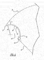
FIG. 1 is a plan view of an oscillating cutting blade in accordance with the disclosure. -
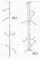
FIG. 2 is a side elevation view of the cutting blade ofFIG. 1 . -
FIG. 3 is a cross-section view along line 3-3 ofFIG. 1 thereof. -
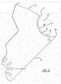
FIG. 4 is an enlarged view of the first cutting surface. -
FIG. 5 is an enlarged view of the second cutting surface. -
FIG. 6 is a perspective view of the oscillating cutting blade ofFIG. 1 coupled to an oscillating power tool and being used to cut a workpiece with the first cutting surface in a pulling direction. -
FIG. 7 is a perspective view of the oscillating cutting blade ofFIG. 1 coupled to an oscillating power tool and being used to cut a workpiece with the second cutting surface in a pushing direction. - Example embodiments will now be described more fully with reference to the accompanying drawings.
- Turning to the figures, an oscillating cutting blade is illustrated and designated with the
reference numeral 10. The oscillatingcutting blade 10 includes abody 12 having anattachment mechanism 14, afirst cutting surface 16 and asecond cutting surface 18. Theattachment mechanism 14 enables cuttingblade 10 to be removably coupled to an oscillatingpower tool 50 so that the blade can oscillate relative to thepower tool 50. The illustrated attachment mechanism is similar to one of the attachment mechanisms disclosed in Applicant's pendingU.S. Patent Application No. 13/781,900 - The
body 12 generally has the shape of a sector of a circle, with the sector bounded by afirst side edge 20, asecond side edge 22, and athird side edge 24. Theattachment mechanism 14 is positioned roughly at or near a center of the circle defined by the sector-shaped body 12. The first andsecond side edges attachment mechanism 14. Thethird side edge 24 has an arcuate shape that extends partially along a circumference of the circle defined by the sector. In one embodiment, the sector comprises approximately an overall approximately 90° sector design. Thebody 12 is substantially flat and planar. The body is generally manufactured from a steel material, such as hardened spring steel (e.g., SK5 steel), although other suitable materials may be used. The body generally has a hardness of approximately 45 HRC to approximately 50 HRC. - Referring to
FIG. 4 , thefirst cutting surface 16 comprises a first hook shaped cutting surface formed in thefirst side edge 20 and intersecting thethird edge 24 at afirst cutting tip 27. As shown inFIG. 1 , thefirst cutting surface 16 and cuttingtip 27 face generally toward theattachment mechanism 14. Thefirst edge 20 includes aninclined portion 26 that extends inward from thefirst edge 20 to anorigin 29 of thefirst cutting surface 16. Theinclined portion 26 is on a desired angle β relative to thefirst edge 20, which can be between approximately 30° and approximately 40°, for example, 35°. Theinclined portion 26 enables thefirst cutting surface 16 to enter a workpiece (material to be cut) so that the oscillatingblade 16 may be moved in a pulling direction, as discussed further below. This enables easy access to the workpiece by the oscillatingcutting blade 10. - Referring to
FIG. 5 , thesecond cutting surface 18 comprises a second hook shaped cutting surface formed in thethird edge 24 and intersecting thesecond edge 22 at asecond cutting tip 28. As shown inFIG. 1 , thesecond cutting surface 18 faces generally away from theattachment mechanism 14. Thethird edge 24 is joined with and terminates at anorigin 31 of thesecond cutting surface 18. Thesecond edge 22 forms thesecond cutting tip 28 with thesecond cutting surface 18. This configuration enables thesecond cutting surface 18 to cut material in a pushing direction of the oscillating power tool, as discussed in greater detail below. - The
cutting surface 16 is arcuate and has a desired radius (R1). The radius (R1) is between approximately 10mm and approximately 20mm, for example 14mm. The arc portion of thefirst cutting surface 16 has a circumferential length between approximately 100° and approximately 150°, for example, between approximately 125° and approximately 130°. Thecutting surface 16 includes abeveled surface 30. The beveled surface extends at an angle of between approximately 25° and approximately 35°, for example, approximately 30°, with respect to the horizontal, as illustrated inFIG. 3 and is designated with the α designation. Thebeveled surface 30 with thebottom body surface 36 forms arcuatecutting edge 38. Thecutting edge 38 enhances the cutting performance of thecutting surfaces 16. As illustrated inFIG. 1 , thebeveled surface 30 extends in the same direction asbeveled surface 32, although it should be understood that they may be beveled in opposite directions. In the illustrated example, thebeveled surface 30 is beveled towards thetop body surface 34. - The
first cutting tip 27 is angled with respect to theedge 22 on an angle γ1 between approximately 30° and approximately 40°, for example approximately 35°. This angle enhances the cutting of the workpiece during a pulling force applied onto thecutting tip 27 of the oscillating blade, as shown inFIG. 6 . Also, the angle enables thecutting tip 27 to puncture through the workpiece to start the cutting in a pulling direction. Thus, the arcuatecutting edge 38 cuts through the workpiece when the oscillatingblade 10 is in use on an oscillating tool. - The
cutting surface 18 is arcuate and has a desired radius (R2). The radius (R2) is between approximately 10mm and approximately 20mm, for example, 14mm. The arc portion of thesecond cutting surface 18 has a circumferential length between approximately 120° and approximately 180°, for example, between approximately 135° and 140°. Thecutting surface 18 includes abeveled surface 32. The beveled surface extends at an angle of between approximately 25° and approximately 35°, for example approximately 30°, with respect to the horizontal, as illustrated inFIG. 3 and is designated with the α designation. Thebeveled surface 32, with thebottom body surface 36, forms thearcuate cutting edge 40. Thecutting edge 40 enhances the cutting performance of the cutting surfaces 18. As illustrated inFIG. 1 , thebeveled surface 32 extends in the same direction asbeveled surface 30, although it should be understood that they may be beveled in opposite directions. In the illustrated example, thebeveled surface 32 is beveled towards thetop body surface 34. - The
second cutting tip 28 is angled with respect to theedge 22 on an angle γ2 between approximately 25° and approximately 35°, for example, between approximately 29° and approximately 33°. This angle enhances the cutting of the workpiece during a pushing force applied onto the cuttingtip 28 of the oscillating blade as shown inFIG. 7 . Also, the angle enables the cuttingtip 28 to puncture through the workpiece to start the cutting in a pushing direction. Thus, thearcuate cutting edge 40 cuts through the workpiece when theoscillating blade 10 is in use on an oscillating tool. - Turning to
FIGS. 6 and7 , an oscillating power tool is illustrated and designated with thereference numeral 50. Theoscillating power tool 50 is coupled with theoscillating blade 10 via theattachment mechanism 14 as illustrated inFIG. 7 . Aclamp mechanism 52 secures theoscillating blade 10 with theoscillating power tool 50. The clamp mechanism may be configured similar to the clamp mechanisms described in commonly owned United States Patent Application No.13/362,637 - As seen in
FIG. 6 , thefirst cutting surface 16 ofblade 10 is utilized in a pulling direction A to cut through aworkpiece 54, illustrated as a shingle. Here, thetip 27 could puncture theworkpiece 54 or the cuttingsurface 16 could be directly applied into contact with theworkpiece 54, followed by pulling theoscillating tool 50 in the direction A. -
FIG. 7 illustrates thesecond cutting surface 18 of oscillatingblade 10 cutting through theworkpiece 54, such as shingle, in the pushing direction B. Here, the cuttingtip 28 can be used to puncture theworkpiece 54 and the cuttingsurface 18 is pushed in the direction B while in contact with theworkpiece 54. Thus, theoscillating cutting blade 10 can be utilized in both a pushing and pulling direction when it is connected with theoscillating power tool 50. - The foregoing description of the embodiments has been provided for purposes of illustration and description. It is not intended to be exhaustive or to limit the disclosure. Individual elements or features of a particular embodiment are generally not limited to that particular embodiment, but, where applicable, are interchangeable and can be used in a selected embodiment, even if not specifically shown or described. For example, the first, second, and/or third edges may include additional teeth and/or cutting surfaces. The
inclined surface 26 may be eliminated. The same may also be varied in many ways. Such variations are not to be regarded as a departure from the disclosure, and all such modifications are intended to be included within the scope of the claims.
Claims (6)
- An oscillating cutting blade (10) comprising:a body (12) generally having a shape of a sector of a circle bounded by first (20), second (22), and third (24) side edges;an attachment mechanism (14) for coupling with an oscillating power tool, the attachment mechanism (14) enabling the body (12) to be removably coupled to the oscillating power tool to be driven in an oscillating manner by the oscillating power tool;characterized in that the first (20) and second (22) side edges extend generally radially outward from the attachment mechanism and the third side edge (24) has a generally arcuate shape partially extending along a circumference of the circle, the oscillating blade further comprising;a first cutting surface (16) on the body (12), the first cutting surface (16) configured to cut a workpiece in a pulling direction, wherein the first cutting surface (16) comprises a first hook shaped recess formed in the first side edge (20) and intersecting the third edge (24) at a first cutting tip (27); anda second cutting surface (18) on the body (12), the second cutting surface (18) configured to cut the workpiece in a pushing direction, wherein the second cutting surface (18) comprises a second hook shaped recess formed in the third edge (24) and intersecting the second edge (22) at a second cutting tip (28).
- The oscillating cutting blade of claim 1, wherein the attachment mechanism (14) is positioned approximately near a center of the circle that defines the sector.
- The oscillating cutting blade of Claim 1 or Claim 2, wherein the body (12) has an overall approximately 90° sector design.
- The oscillating cutting blade of any one of the preceding claims, wherein an inclined surface (26) extends from the first edge (20) of the body (12) to intersect an origin (29) of the first cutting surface (16).
- The oscillating cutting blade of any one of the preceding claims, wherein the second cutting surface (18) originates on the third edge (24) of the body.
- The oscillating cutting blade of any one of the preceding claims, wherein each of the first (16) and second (18) cutting surfaces is arcuate and/or includes a beveled surface and/or includes a cutting tip.
Applications Claiming Priority (1)
| Application Number | Priority Date | Filing Date | Title |
|---|---|---|---|
| US13/898,967 US20140345148A1 (en) | 2013-05-21 | 2013-05-21 | Cutting Blade For Use With Oscillating Power Tool |
Publications (2)
| Publication Number | Publication Date |
|---|---|
| EP2808137A1 EP2808137A1 (en) | 2014-12-03 |
| EP2808137B1 true EP2808137B1 (en) | 2017-05-24 |
Family
ID=49584647
Family Applications (1)
| Application Number | Title | Priority Date | Filing Date |
|---|---|---|---|
| EP13193072.9A Active EP2808137B1 (en) | 2013-05-21 | 2013-11-15 | Cutting blade for use with oscillating power tool |
Country Status (2)
| Country | Link |
|---|---|
| US (1) | US20140345148A1 (en) |
| EP (1) | EP2808137B1 (en) |
Families Citing this family (5)
| Publication number | Priority date | Publication date | Assignee | Title |
|---|---|---|---|---|
| USD832666S1 (en) * | 2012-07-16 | 2018-11-06 | Black & Decker Inc. | Oscillating saw blade |
| US10843282B2 (en) | 2017-08-16 | 2020-11-24 | Imperial Blades | Oscillating blade with universal arbor engagement portion |
| US20190240752A1 (en) | 2018-02-02 | 2019-08-08 | Imperial Blades | Oscillating tool drywall blade |
| WO2021076750A1 (en) * | 2019-10-18 | 2021-04-22 | Milwaukee Electric Tool Corporation | Blade for a power tool |
| USD1027587S1 (en) * | 2021-04-19 | 2024-05-21 | Hangzhou Great Star Industrial Co., Ltd. | Saw blade |
Family Cites Families (9)
| Publication number | Priority date | Publication date | Assignee | Title |
|---|---|---|---|---|
| US4615119A (en) * | 1984-04-26 | 1986-10-07 | Jhj Enterprises | Blade for a vibratory cutter |
| DE4310832C2 (en) * | 1993-04-02 | 1995-07-13 | Rowenta Werke Gmbh | Cutting device |
| DE102004044135A1 (en) * | 2004-09-13 | 2006-03-30 | Robert Bosch Gmbh | tool attachment |
| DE102010040131A1 (en) * | 2010-09-02 | 2012-03-08 | Robert Bosch Gmbh | Oscillating insert tool and hole saw insert tool |
| DE202011052282U1 (en) * | 2010-12-14 | 2012-03-21 | Techtronic Power Tools Technology Ltd. | Accessories with multiple blades |
| EP2551077A1 (en) * | 2011-07-26 | 2013-01-30 | A O Schallinox GmbH | Blade for splitting goods for processing using ultrasound energy and device |
| US9027452B2 (en) * | 2011-12-27 | 2015-05-12 | Robert Bosch Gmbh | Jab saw accessory tool for an oscillating tool |
| US10532472B2 (en) * | 2012-01-04 | 2020-01-14 | Robert Bosch Tool Corporation | Hook blade accessory tool for an oscillating tool |
| USD706595S1 (en) * | 2013-05-21 | 2014-06-10 | Black & Decker Inc. | Oscillating cutting blade |
-
2013
- 2013-05-21 US US13/898,967 patent/US20140345148A1/en not_active Abandoned
- 2013-11-15 EP EP13193072.9A patent/EP2808137B1/en active Active
Also Published As
| Publication number | Publication date |
|---|---|
| US20140345148A1 (en) | 2014-11-27 |
| EP2808137A1 (en) | 2014-12-03 |
Similar Documents
| Publication | Publication Date | Title |
|---|---|---|
| US11344960B2 (en) | Oscillating blade with universal arbor engagement portion | |
| EP2808137B1 (en) | Cutting blade for use with oscillating power tool | |
| US20240017335A1 (en) | Hole saw | |
| US10092963B2 (en) | Toothform for a cutting tool, such as a hole saw | |
| US8381625B2 (en) | Circular saw blade with cutting tips mechanically locked against multiple force vectors | |
| US20160082605A1 (en) | Cutting blade for oscillating tool | |
| US10335980B2 (en) | Dust suction drill and dust suction unit | |
| AU2013206854B2 (en) | Hook blade accessory tool for an oscillating tool | |
| US10029315B2 (en) | Drill bit | |
| EP3038777B1 (en) | Detachable cutting tool segment with resilient clamping and cutting tool therefor | |
| EP1992463A2 (en) | Rotational cutting tool | |
| JP4583274B2 (en) | File | |
| US10512978B2 (en) | Blade and blade attachment system for an oscillating tool | |
| KR101419112B1 (en) | Cutting tip for core type shank | |
| FR3011267A1 (en) | CUTTING PAD AND ASSOCIATED DRILLING TOOL | |
| TWM460726U (en) | Turning tool structure for arc trough and turning tool blade thereof | |
| TWM536109U (en) | Tungsten carbide cutter |
Legal Events
| Date | Code | Title | Description |
|---|---|---|---|
| PUAI | Public reference made under article 153(3) epc to a published international application that has entered the european phase |
Free format text: ORIGINAL CODE: 0009012 |
|
| 17P | Request for examination filed |
Effective date: 20131115 |
|
| AK | Designated contracting states |
Kind code of ref document: A1 Designated state(s): AL AT BE BG CH CY CZ DE DK EE ES FI FR GB GR HR HU IE IS IT LI LT LU LV MC MK MT NL NO PL PT RO RS SE SI SK SM TR |
|
| AX | Request for extension of the european patent |
Extension state: BA ME |
|
| R17P | Request for examination filed (corrected) |
Effective date: 20150601 |
|
| RBV | Designated contracting states (corrected) |
Designated state(s): AL AT BE BG CH CY CZ DE DK EE ES FI FR GB GR HR HU IE IS IT LI LT LU LV MC MK MT NL NO PL PT RO RS SE SI SK SM TR |
|
| 17Q | First examination report despatched |
Effective date: 20150728 |
|
| RIC1 | Information provided on ipc code assigned before grant |
Ipc: B26D 1/00 20060101ALI20161006BHEP Ipc: B26D 7/08 20060101AFI20161006BHEP |
|
| GRAP | Despatch of communication of intention to grant a patent |
Free format text: ORIGINAL CODE: EPIDOSNIGR1 |
|
| RIN1 | Information on inventor provided before grant (corrected) |
Inventor name: NIBLETT, JAMES R. Inventor name: KAYE JR., THOMAS R. |
|
| INTG | Intention to grant announced |
Effective date: 20161215 |
|
| GRAS | Grant fee paid |
Free format text: ORIGINAL CODE: EPIDOSNIGR3 |
|
| GRAA | (expected) grant |
Free format text: ORIGINAL CODE: 0009210 |
|
| AK | Designated contracting states |
Kind code of ref document: B1 Designated state(s): AL AT BE BG CH CY CZ DE DK EE ES FI FR GB GR HR HU IE IS IT LI LT LU LV MC MK MT NL NO PL PT RO RS SE SI SK SM TR |
|
| REG | Reference to a national code |
Ref country code: GB Ref legal event code: FG4D |
|
| REG | Reference to a national code |
Ref country code: CH Ref legal event code: EP |
|
| REG | Reference to a national code |
Ref country code: IE Ref legal event code: FG4D |
|
| REG | Reference to a national code |
Ref country code: AT Ref legal event code: REF Ref document number: 895787 Country of ref document: AT Kind code of ref document: T Effective date: 20170615 |
|
| REG | Reference to a national code |
Ref country code: SE Ref legal event code: TRGR |
|
| REG | Reference to a national code |
Ref country code: DE Ref legal event code: R096 Ref document number: 602013021483 Country of ref document: DE |
|
| REG | Reference to a national code |
Ref country code: NL Ref legal event code: MP Effective date: 20170524 |
|
| REG | Reference to a national code |
Ref country code: LT Ref legal event code: MG4D |
|
| REG | Reference to a national code |
Ref country code: FR Ref legal event code: PLFP Year of fee payment: 5 |
|
| REG | Reference to a national code |
Ref country code: AT Ref legal event code: MK05 Ref document number: 895787 Country of ref document: AT Kind code of ref document: T Effective date: 20170524 |
|
| PG25 | Lapsed in a contracting state [announced via postgrant information from national office to epo] |
Ref country code: AT Free format text: LAPSE BECAUSE OF FAILURE TO SUBMIT A TRANSLATION OF THE DESCRIPTION OR TO PAY THE FEE WITHIN THE PRESCRIBED TIME-LIMIT Effective date: 20170524 Ref country code: ES Free format text: LAPSE BECAUSE OF FAILURE TO SUBMIT A TRANSLATION OF THE DESCRIPTION OR TO PAY THE FEE WITHIN THE PRESCRIBED TIME-LIMIT Effective date: 20170524 Ref country code: GR Free format text: LAPSE BECAUSE OF FAILURE TO SUBMIT A TRANSLATION OF THE DESCRIPTION OR TO PAY THE FEE WITHIN THE PRESCRIBED TIME-LIMIT Effective date: 20170825 Ref country code: NO Free format text: LAPSE BECAUSE OF FAILURE TO SUBMIT A TRANSLATION OF THE DESCRIPTION OR TO PAY THE FEE WITHIN THE PRESCRIBED TIME-LIMIT Effective date: 20170824 Ref country code: HR Free format text: LAPSE BECAUSE OF FAILURE TO SUBMIT A TRANSLATION OF THE DESCRIPTION OR TO PAY THE FEE WITHIN THE PRESCRIBED TIME-LIMIT Effective date: 20170524 Ref country code: LT Free format text: LAPSE BECAUSE OF FAILURE TO SUBMIT A TRANSLATION OF THE DESCRIPTION OR TO PAY THE FEE WITHIN THE PRESCRIBED TIME-LIMIT Effective date: 20170524 Ref country code: FI Free format text: LAPSE BECAUSE OF FAILURE TO SUBMIT A TRANSLATION OF THE DESCRIPTION OR TO PAY THE FEE WITHIN THE PRESCRIBED TIME-LIMIT Effective date: 20170524 |
|
| PG25 | Lapsed in a contracting state [announced via postgrant information from national office to epo] |
Ref country code: BG Free format text: LAPSE BECAUSE OF FAILURE TO SUBMIT A TRANSLATION OF THE DESCRIPTION OR TO PAY THE FEE WITHIN THE PRESCRIBED TIME-LIMIT Effective date: 20170824 Ref country code: NL Free format text: LAPSE BECAUSE OF FAILURE TO SUBMIT A TRANSLATION OF THE DESCRIPTION OR TO PAY THE FEE WITHIN THE PRESCRIBED TIME-LIMIT Effective date: 20170524 Ref country code: RS Free format text: LAPSE BECAUSE OF FAILURE TO SUBMIT A TRANSLATION OF THE DESCRIPTION OR TO PAY THE FEE WITHIN THE PRESCRIBED TIME-LIMIT Effective date: 20170524 Ref country code: IS Free format text: LAPSE BECAUSE OF FAILURE TO SUBMIT A TRANSLATION OF THE DESCRIPTION OR TO PAY THE FEE WITHIN THE PRESCRIBED TIME-LIMIT Effective date: 20170924 Ref country code: LV Free format text: LAPSE BECAUSE OF FAILURE TO SUBMIT A TRANSLATION OF THE DESCRIPTION OR TO PAY THE FEE WITHIN THE PRESCRIBED TIME-LIMIT Effective date: 20170524 |
|
| PG25 | Lapsed in a contracting state [announced via postgrant information from national office to epo] |
Ref country code: DK Free format text: LAPSE BECAUSE OF FAILURE TO SUBMIT A TRANSLATION OF THE DESCRIPTION OR TO PAY THE FEE WITHIN THE PRESCRIBED TIME-LIMIT Effective date: 20170524 Ref country code: CZ Free format text: LAPSE BECAUSE OF FAILURE TO SUBMIT A TRANSLATION OF THE DESCRIPTION OR TO PAY THE FEE WITHIN THE PRESCRIBED TIME-LIMIT Effective date: 20170524 Ref country code: RO Free format text: LAPSE BECAUSE OF FAILURE TO SUBMIT A TRANSLATION OF THE DESCRIPTION OR TO PAY THE FEE WITHIN THE PRESCRIBED TIME-LIMIT Effective date: 20170524 Ref country code: EE Free format text: LAPSE BECAUSE OF FAILURE TO SUBMIT A TRANSLATION OF THE DESCRIPTION OR TO PAY THE FEE WITHIN THE PRESCRIBED TIME-LIMIT Effective date: 20170524 Ref country code: SK Free format text: LAPSE BECAUSE OF FAILURE TO SUBMIT A TRANSLATION OF THE DESCRIPTION OR TO PAY THE FEE WITHIN THE PRESCRIBED TIME-LIMIT Effective date: 20170524 |
|
| REG | Reference to a national code |
Ref country code: DE Ref legal event code: R097 Ref document number: 602013021483 Country of ref document: DE |
|
| PG25 | Lapsed in a contracting state [announced via postgrant information from national office to epo] |
Ref country code: IT Free format text: LAPSE BECAUSE OF FAILURE TO SUBMIT A TRANSLATION OF THE DESCRIPTION OR TO PAY THE FEE WITHIN THE PRESCRIBED TIME-LIMIT Effective date: 20170524 Ref country code: SM Free format text: LAPSE BECAUSE OF FAILURE TO SUBMIT A TRANSLATION OF THE DESCRIPTION OR TO PAY THE FEE WITHIN THE PRESCRIBED TIME-LIMIT Effective date: 20170524 Ref country code: PL Free format text: LAPSE BECAUSE OF FAILURE TO SUBMIT A TRANSLATION OF THE DESCRIPTION OR TO PAY THE FEE WITHIN THE PRESCRIBED TIME-LIMIT Effective date: 20170524 |
|
| PLBE | No opposition filed within time limit |
Free format text: ORIGINAL CODE: 0009261 |
|
| STAA | Information on the status of an ep patent application or granted ep patent |
Free format text: STATUS: NO OPPOSITION FILED WITHIN TIME LIMIT |
|
| 26N | No opposition filed |
Effective date: 20180227 |
|
| PG25 | Lapsed in a contracting state [announced via postgrant information from national office to epo] |
Ref country code: SI Free format text: LAPSE BECAUSE OF FAILURE TO SUBMIT A TRANSLATION OF THE DESCRIPTION OR TO PAY THE FEE WITHIN THE PRESCRIBED TIME-LIMIT Effective date: 20170524 |
|
| PG25 | Lapsed in a contracting state [announced via postgrant information from national office to epo] |
Ref country code: MC Free format text: LAPSE BECAUSE OF FAILURE TO SUBMIT A TRANSLATION OF THE DESCRIPTION OR TO PAY THE FEE WITHIN THE PRESCRIBED TIME-LIMIT Effective date: 20170524 |
|
| PG25 | Lapsed in a contracting state [announced via postgrant information from national office to epo] |
Ref country code: CH Free format text: LAPSE BECAUSE OF NON-PAYMENT OF DUE FEES Effective date: 20171130 Ref country code: LI Free format text: LAPSE BECAUSE OF NON-PAYMENT OF DUE FEES Effective date: 20171130 |
|
| PG25 | Lapsed in a contracting state [announced via postgrant information from national office to epo] |
Ref country code: LU Free format text: LAPSE BECAUSE OF NON-PAYMENT OF DUE FEES Effective date: 20171115 |
|
| REG | Reference to a national code |
Ref country code: BE Ref legal event code: MM Effective date: 20171130 |
|
| REG | Reference to a national code |
Ref country code: IE Ref legal event code: MM4A |
|
| PG25 | Lapsed in a contracting state [announced via postgrant information from national office to epo] |
Ref country code: MT Free format text: LAPSE BECAUSE OF NON-PAYMENT OF DUE FEES Effective date: 20171115 |
|
| REG | Reference to a national code |
Ref country code: FR Ref legal event code: PLFP Year of fee payment: 6 |
|
| PG25 | Lapsed in a contracting state [announced via postgrant information from national office to epo] |
Ref country code: IE Free format text: LAPSE BECAUSE OF NON-PAYMENT OF DUE FEES Effective date: 20171115 |
|
| PG25 | Lapsed in a contracting state [announced via postgrant information from national office to epo] |
Ref country code: BE Free format text: LAPSE BECAUSE OF NON-PAYMENT OF DUE FEES Effective date: 20171130 |
|
| PGFP | Annual fee paid to national office [announced via postgrant information from national office to epo] |
Ref country code: SE Payment date: 20181016 Year of fee payment: 6 |
|
| PGFP | Annual fee paid to national office [announced via postgrant information from national office to epo] |
Ref country code: FR Payment date: 20181011 Year of fee payment: 6 |
|
| PG25 | Lapsed in a contracting state [announced via postgrant information from national office to epo] |
Ref country code: HU Free format text: LAPSE BECAUSE OF FAILURE TO SUBMIT A TRANSLATION OF THE DESCRIPTION OR TO PAY THE FEE WITHIN THE PRESCRIBED TIME-LIMIT; INVALID AB INITIO Effective date: 20131115 |
|
| PG25 | Lapsed in a contracting state [announced via postgrant information from national office to epo] |
Ref country code: CY Free format text: LAPSE BECAUSE OF FAILURE TO SUBMIT A TRANSLATION OF THE DESCRIPTION OR TO PAY THE FEE WITHIN THE PRESCRIBED TIME-LIMIT Effective date: 20170524 |
|
| PG25 | Lapsed in a contracting state [announced via postgrant information from national office to epo] |
Ref country code: MK Free format text: LAPSE BECAUSE OF FAILURE TO SUBMIT A TRANSLATION OF THE DESCRIPTION OR TO PAY THE FEE WITHIN THE PRESCRIBED TIME-LIMIT Effective date: 20170524 |
|
| PG25 | Lapsed in a contracting state [announced via postgrant information from national office to epo] |
Ref country code: TR Free format text: LAPSE BECAUSE OF FAILURE TO SUBMIT A TRANSLATION OF THE DESCRIPTION OR TO PAY THE FEE WITHIN THE PRESCRIBED TIME-LIMIT Effective date: 20170524 |
|
| PG25 | Lapsed in a contracting state [announced via postgrant information from national office to epo] |
Ref country code: PT Free format text: LAPSE BECAUSE OF FAILURE TO SUBMIT A TRANSLATION OF THE DESCRIPTION OR TO PAY THE FEE WITHIN THE PRESCRIBED TIME-LIMIT Effective date: 20170524 |
|
| REG | Reference to a national code |
Ref country code: SE Ref legal event code: EUG |
|
| PG25 | Lapsed in a contracting state [announced via postgrant information from national office to epo] |
Ref country code: AL Free format text: LAPSE BECAUSE OF FAILURE TO SUBMIT A TRANSLATION OF THE DESCRIPTION OR TO PAY THE FEE WITHIN THE PRESCRIBED TIME-LIMIT Effective date: 20170524 |
|
| PG25 | Lapsed in a contracting state [announced via postgrant information from national office to epo] |
Ref country code: SE Free format text: LAPSE BECAUSE OF NON-PAYMENT OF DUE FEES Effective date: 20191116 |
|
| PG25 | Lapsed in a contracting state [announced via postgrant information from national office to epo] |
Ref country code: FR Free format text: LAPSE BECAUSE OF NON-PAYMENT OF DUE FEES Effective date: 20191130 |
|
| PGFP | Annual fee paid to national office [announced via postgrant information from national office to epo] |
Ref country code: GB Payment date: 20230921 Year of fee payment: 11 |
|
| PGFP | Annual fee paid to national office [announced via postgrant information from national office to epo] |
Ref country code: DE Payment date: 20230919 Year of fee payment: 11 |